
Bending Response of HSRC Beams Strengthened with FRP...
9
Transcript of Bending Response of HSRC Beams Strengthened with FRP...
Transaction A: Civil EngineeringVol. 16, No. 2, pp. 138{146c Sharif University of Technology, April 2009
Bending Response of HSRC BeamsStrengthened with FRP Sheets
S.H. Hashemi1;�, A.A. Maghsoudi2 and R. Rahgozar2
Abstract. The repair and strengthening of RC structures has become a major problem for civilengineers in the past few decades. To satisfy this problem, a previous method for the repair andstrengthening of RC beams included bonding steel plates to the inferior structure. However, bonding steelplates to concrete presents disadvantages, including corrosion of the steel/adhesive joints and the heavyweight of the material. These problems increase installation and maintenance costs. The bonding of FiberReinforced Plastics (FRP) to structures provides an attractive alternative to steel plates. This materialis corrosion resistant and lightweight, has a high strength-to-weight ratio and possesses nonconductiveproperties. The use of Fiber Reinforced Plastics (FRP) in repairing and strengthening RC beams has beenresearched in recent years. In particular, attaching unidirectional FRP to the tension face of RC beams hasprovided an increase in the sti�ness and load capacity of the structure. However, due to the brittle natureof unidirectional FRP, the ductility of the beam decreases. Consequently, the safety of the structure iscompromised, due to the reduction in ductility. The purpose of this research is to investigate the behaviorof high strength reinforced concrete beams strengthened with FRP sheets. The major test variables includedthe di�erent layouts of CFRP sheets and the tensile reinforcement ratio. More particularly, change in thestrength and ductility of the beams, as the number of FRP layers and tensile reinforcement bar ratios arealtered, is investigated. Eight under-reinforced concrete beams were fabricated and tested to failure. Withthe exception of the control beam, one or four layers of CFRP were applied to the specimens.
Keywords: Beams; Ductility; FRP; High strength concrete; Tensile bars.
INTRODUCTION
High strength-to-weight ratio, resistance to electro-chemical corrosion, larger creep strain, good fatiguestrength, potential for decreased installation costs andrepairs, due to lower weight, in comparison with steel,and the nonmagnetic and non-metallic properties ofFiber Reinforced Polymer (FRP) composites, o�er aviable alternative to the bonding of steel plates. Theemergence of high strength epoxies has also enhancedthe feasibility of using CFRP sheets and a carbon �berfabric for repair and rehabilitation.
The failure modes of concrete beams retro�ttedwith FRP materials and the techniques used in an-alyzing the failure modes were reviewed by Toutanji
1. Faculty of Engineering, Arak University, Arak, P.O. Box38139, Iran.
2. Department of Civil Engineering, University of Kerman,Kerman, P.O. Box 76169-14111, Iran.
*. Corresponding author. E-mail: [email protected]
Received 5 December 2006; accepted 13 May 2008
et al. [1]. The behavior of concrete beams strength-ened with externally bonded steel plates [2], FRPplates [3,4], carbon �ber fabric [5,6] and GFRPsheets [7] was studied both experimentally and analyt-ically. Malek et al. [8] presented analytical proceduresto calculate the exural strength of RC beams bondedwith FRP plates. To date, extensive research workhas been conducted on the exural strength of concretebeams bonded with various types of FRP composites.
Advances in concrete technology in many coun-tries have now made practical use of concrete withstrengths up to 90 MPa. These concretes, with veryhigh compressive strength, can result in less ductileresponses of structural members. It has been foundthat exural ductility, in terms of maximum curvaturesattainable, may be smaller in HSC beams [9]. Inseismic areas, ductility is an important factor in thedesign of HSC members under exure. The use ofHSC beams strengthened with CFRP and ductilityhas not been the focus of much previous experimentalresearch work and, consequently, will be focused on

Reinforced HSC Beams Strengthened with FRP Sheets 139
in this study. Although external strengthening of RCbeams using epoxy-bonded FRP has been establishedas an e�ective tool for increasing their exural and/orshear strength, the method still su�ers from somedrawbacks. Many of these drawbacks are attributedto the characteristics of currently available commercialFRP strengthening systems. Although FRPs havehigh strengths, they are very brittle. When loaded intension, FRPs exhibit a linear stress-strain behaviorup to failure without exhibiting a yield plateau or anyindication of an impending failure.
The objective of this investigation is to study thee�ectiveness of FRP sheets on the ductility and exuralstrength of High Strength Reinforced Concrete (HSRC)beams. This objective is achieved by conducting thefollowing tasks:
1. Flexural testing of HSRC beams strengthened withdi�erent amounts of cross-ply FRP sheets withdi�erent amounts of tensile reinforcement;
2. Calculating the e�ect of di�erent layouts of FRPsheets on exural strength;
3. Evaluating the failure modes.
HSRC LABORATORY BEAM SPECIMENS
Beam Detail, Instrumentation and TestProcedure
Four-point bending exural tests were conducted upto failure on two HSRC control beams and six HSRCbeams strengthened with externally bonded FRPsheets on the tension face. The length, width and depth(L�b�h) of all beams were kept as 3000�150�250 mm.Each concrete beam was reinforced with two 16-mmdiameters for A series and two 22-mm diameters for Bseries steel bars, for tension, and two 10-mm-diametersteel bars for compression, along with 10-mm-diameterbars at a spacing of 90 mm center-to-center for shear
reinforcement. The spacing of stirrups and maximumand minimum reinforcement ratios are in accordancewith the provisions of the American Concrete Institute(ACI).
Electrical resistance disposable strain gauges,manufactured by the TML Measurements Group(Japan), were pasted on the CFRP sheets and oninternal reinforcing bars at di�erent locations. Thedemec and electrical gauges were also attached alongthe height of the beams to measure the concretestrains; these values can be used to �nd the straindistribution and the moving neutral axis depth of thebeams tested. All beams were loaded in four-pointbending to failure with a clear span of 2.7 m, andloading points were located at 450 mm on either sideof the mid-span location. The load was applied step-by-step up to failure in the load control manner oftest beams. During the test, the strains on steel andconcrete, and vertical de ections were measured usingLVDTs. The strain gauges, LVDTs and the load cellwere connected through a data acquisition system to acomputer and the data was recorded and stored in thecomputer (Figure 1).
For all beams, the shear-span-to-depth ratios are4.18 and the length of the bonded plate is 2600 mm,which covers almost the full-span length between thesupports of the beams. The reason for the full-span-length strengthening with FRP plates is to maximizethe strengthening e�ects by delaying FRP separation.
Material Properties
The concrete in the beams was designed for a mean28-day cube strength of about 100 MPa. For eachbeam, three 100 mm�100 mm�100 mm concrete cubespecimens were made at the time of casting and theywere kept with the beams during curing. The average28-day concrete cube strength (fcu) was 96.2 MPa. The
Figure 1. Beam details and measurement schemes for half of the test specimen (unit: millimeter).
140 S.H. Hashemi, A.A. Maghsoudi and R. Rahgozar
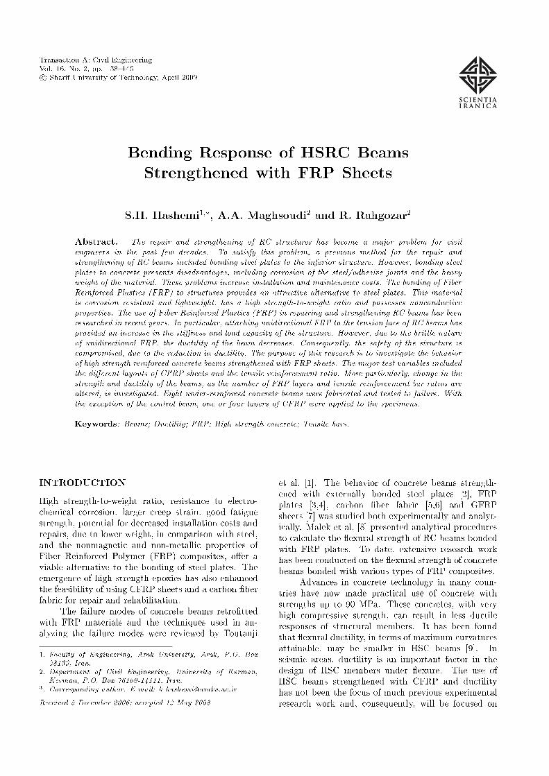
Figure 2. Stress-strain diagram for high strengthconcrete.
relationship of cylinder strength (f 0c) and cube strengthwas assumed as (f 0c = 0:8fcu) and the stress-straincurves for the cube specimens are shown in Figure 2.Thus, the average compressive strength (f 0c) was 77MPa.
The measured yield and maximum tensilestrength of the 10 and 16 mm rebars were 420.6,634.1 and 412.5, 626.4 MPa, respectively. The densityand thickness of the CFRP and GFRP material was1:78 � 0:1 gr/cm3, 0.045 mm and 2:6 � 0:1 gr/cm3,0.114 mm, respectively, and 2600 mm long for both ofthem. The Young's modulus (Efu), ultimate tensilestress (ffu) and elongation ("fu) of the FRP sheetswere 230 GPa, 3850 MPa and 1:7 � 0:1% for CFRPand 71 GPa, 2900 MPa and 4:5 � 0:5% for GFRP,respectively. FRP sheets were externally bonded tothe tension face of the concrete beams using a two-component structural epoxy named EP-TX at a 1:1ratio for the �rst layer and a two-part epoxy namedEP-IN at a 1:1 ratio for the next layer(s) of FRP.Strengthened concrete beams were cured for at leastseven days at room temperature before testing.
Major Test Variables
The main test variables considered in the presentstudy include the FRP sheet layers and tensile bars.The FRP sheet layers vary from 0 to 6 and the barreinforcement ratio varies from 1.2% to 2.4%. Thetest program is summarized in Table 1. Of the eightbeams tested, two were set aside as control beams andwere not strengthened (AH0, BH0), two beam werestrengthened with one layer of CFRP (AH1, BH1) andtwo beams were strengthened with four layers of CFRP(AH4, BH4), where the width of CFRP was 150 mm.The remaining two beams were strengthened with threelayers of CFRP �rst and then with three layers ofGFRP (ACG3, BCG3); the width of CFRP and GFRPbeing 100 and 150 mm, respectively.
TEST RESULTS AND DISCUSSIONS
Failure Pattern
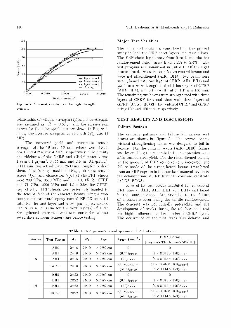
The cracking patterns and failure for various testbeams are shown in Figure 3. The control beamswithout strengthening plates was designed to fail in exure. For the control beams (AH0, BH0), failurewas by crushing the concrete in the compression zoneafter tension steel yield. For the strengthened beams,as the amount of FRP reinforcement increased, thefailure mode of the strengthened beams transferredfrom an FRP rupture in the constant moment region tothe delamination of FRP from the concrete substrate(ACG3, BCG3).
Most of the test beams exhibited the rupture ofFRP sheets (AH1, AH4, BH1 and BH4) and failedin the same manner. We attended to the failureof a concrete cover along the tensile reinforcement.The concrete was not initially precracked and thedevelopment of cracks during the reinforcement testwas highly in uenced by the number of CFRP layers.The occurrence of the �rst crack was delayed and
Table 1. Test parameters and specimen identi�cations.
Series Test Beam AS A0S ASV AFRP (mm2) FRP Detail(Layers�Thickness�Width)
AH0 2�16 2�10 �10@9 cm 0 0AH1 2�16 2�10 �10@9 cm (6:75)CFRP (1� 0:045� 150)CFRP
A AH4 2�16 2�10 �10@9 cm (27)CFRP (4� 0:045� 150)CFRP
ACG3 2�16 2�10 �10@9 cm (13:5)CFRP+(51:3)GFEP
(3� 0:045� 100)CFRP+(3� 0:114� 150)GFRP
BH0 2�22 2�10 �10@9 cm 0 0BH1 2�22 2�10 �10@9 cm (6:75)CFRP (1� 0:045� 150)CFRP
B BH4 2�22 2�10 �10@9 cm (27)CFRP (4� 0:045� 150)CFRP
BCG3 2�22 2�10 �10@9 cm (13:5)CFRP+(51:3)GFEP
(3� 0:045� 100)CFRP+(3� 0:114� 150)GFRP
Reinforced HSC Beams Strengthened with FRP Sheets 141
Figure 3. Failure con�guration of control and FRPbeams at ultimate state.
more di�use. Shear cracks occurred in the shear spanlength of the beams for an applied load, which wasbetween 70% and 80% of the ultimate load. Finally,the sudden propagation of horizontal cracks in theconcrete-steel bond region occurs. This type of cracksruns along the weakest surface, which is the concrete-steel interface. It leads to the failure of the beam assoon as the cracks open and separates the concretecover from the rest of the beam. It is interesting to notethat the weakest point of the assembled concrete-bond-composite material is not the concrete-composite inter-face but the concrete-internal steel interface. Figure 3also indicates that the strengthened beams show many
diagonal cracks, which were caused by the increase of exural capacities, due to CFRP sheets.
From experimental observation, the debondingfailure can be explained as follows: Due to the exuralcracks formed in the constant moment region as theload increased, the bond between FRP and concretestarted to fracture at a certain load level and the failurepropagated towards the shear span until most parts ofFRP composites detached from the concrete beams. Itcan be seen that the bond between FRP and concreteis not strong enough to ensure the rupture of thecomposites with more than four layers of carbon �bersheet; thus, the FRP-concrete bond strength controlsthe failure mode when �ve or six layers of �ber sheetare bonded. When four, or less than four, layers ofcarbon �ber are applied, the bond problem is not thecontrolling factor for failure, thus, the force in FRPwill reach its ultimate tensile capacity when the beamfails.
Discussions on Flexural Behavior
Table 2 summarizes the test results for the peak loads,displacements and strains at peak loads for the testedbeams. Table 2 also shows the increase of peak load,according to the various strengthening layers of FRP.The rates of increase of peak loads varied from 1% to44%, depending upon the strengthening method.
For the strengthened beams in this study, as seenin Table 2 the highest measured strain in the concreteat the beam top surface was 2700 �", which wasreported in beam BH4. This constituted about 77% ofthe ultimate concrete strain at 3500 �", which clearlydemonstrated that failure due to concrete crushing wasnot possible.
The load de ection response for each of thetest beams is plotted in Figure 4. In general, the
Table 2. Test results of the control and CFRP strengthened beams.
Peak Ratio Pult
Series Test Failure Load to Displacement Strain (micron)Beam Modesa Pult Unstrengthened (mm) CFRP Tensile Stirrup Concrete
(kN) Beam Rebar
AH0 C.C 81.25 1 102 - 2316 48 3600A AH1 C.R 89.96 1.11 50.42 844 3341 441 2500
AH4 C.R 117.33 1.44 32.85 2581 9557 954 2100ACG3 D.L 104.7 1.29 26.2 8663 15413 638 1738
BH0 C.C 149.52 1 95.7 - 17843 644 4200B BH1 C.R 150 1.01 63.24 1066 17330 790 2600
BH4 C.R 167 1.12 30.92 3367 4512 - 2700BCG3 D.L 162.23 1.09 26 4327 10375 887 2240
a C.C: Concrete crushing; C.R: CFRP rupture; D.L: FRP delamination.

142 S.H. Hashemi, A.A. Maghsoudi and R. Rahgozar
Figure 4. Load de ection responses of test beams.
strengthened beams were sti�er and less ductile thanthe control specimens with a higher ultimate load. Asa result, compared to a beam reinforced heavily withsteel only, beams reinforced with both steel and CFRPhave an adequate deformation capacity, in spite of theirbrittle mode of failure.
The tension steel in control beams AH0 and BH0reached its yield strength before the compressive strainin concrete reached 0.003 and the beams failed by thecrushing of the concrete. Even though the controlbeams failed by the crushing of concrete, since thefailure was initiated by the yielding of tension steel, themode of failure was mentioned to be under reinforcedtension failure, thus, the behavior of the two controlbeams was a ductile exural response. For controlbeams, after the �rst visible cracks were observed, thecracking became extensive and crack widths increasedsteadily. The shape of the load de ection curvesindicates a loss of sti�ness at a load of approximately64 kN for AH0 and 122 KN for BH0. This was due to
the yielding of the tensile reinforcement and occurredat a midspan de ection of 21 mm for AH0 and 13.3mm for BH0. After this point, large exural cracksopened during the test and eventual ultimate collapseoccurred by concrete crushing within the compressionzone; a photograph of which is presented in Figure 5.The ultimate loads recorded were 81.25 and 149.5 kNfor AH0 and BH0, respectively.
In this study, for AH1, AH4, BH1 and BH4, thebond problem is not the controlling factor for failure,thus, the force in CFRP will reach its ultimate tensilecapacity when the beam fails and the failure modeof the strengthened beams is a CFRP rupture in theconstant moment region. Figure 6 shows such a typicalfailure mode.
As the amount of FRP reinforcement increased,the failure mode of the strengthened beams transferredfrom a FRP rupture in the constant moment region tothe delamination of FRP from the concrete substrate.In this study, beams ACG3 and BCG3 failed by thedebonding of sheets from the concrete surface. Figure 7shows photographs of this failure mode.
Figure 5. Flexural failure of control beam AH0.
Figure 6. Rupture of FRP in beams AH1, AH4, BH1 and BH4.

Reinforced HSC Beams Strengthened with FRP Sheets 143
Table 3. Mid-span de ection and load in yield and ultimate stage of R=C beams strengthened with FRP sheets.
Yield Stage Ultimate StageIncrease Decrease Increase Decrease
Series Test Load over �y over Load over �u overBeam Py (kN) Control (mm) Control Pu (kN) Control (mm) Control
(%) (%) (%) (%)
AH0 63.93 { 21 { 81.25 { 102 {A AH1 69.5 8.7 13 38 89.9 11 50.42 51
AH4 64.7 1.2 9.83 53.2 117.3 44.4 32.85 67.8ACG3 67.33 5.3 10.37 51 104.66 28.8 26.2 74.4
BH0 122.2 { 13.325 { 149.52 { 95.7 {B BH1 130 6.4 14.11 -5.9 150 0.5 63.24 33.9
BH4 118 -3.4 12.86 3.6 167 11.7 30.92 67.7BCG3 130.66 6.9 13.8 -3.6 162.33 8.5 26 72.9
Table 3 shows a summary of the exural be-havior of all test beams, in terms of exural loadingcapacity and de ection. The results clearly demon-strated the accepted bene�cial e�ects of CFRP layers,with regard to the sti�ening and strengthening of thebeams.
The strain response of FRPs is di�erent fromthat of conventional steel, which yields after elasticallydeforming to relatively small values of strain (0.2%for Grade 60 [410 MPa] and 0.14% for Grade 40 [280MPa]). FRP materials exhibit elastic deformation torelatively large strain values before rupture. As aresult, when FRPs are used for the exural strength-ening of concrete beams reinforced with conventionalsteel, the steel reinforcement may yield before theFRP contributes any additional capacity to the beam.Therefore, it can be di�cult to obtain a signi�cantincrease in yield load or sti�ness for a beam. Whenan increase in beam yield load or sti�ness is required,larger cross sections of FRPs must be used (beforethe steel yields), which generally increases the costof strengthening. Although using some special low-strain �bers, such as ultra-high-modulus carbon �bers,may appear to be a solution, they can result in brittlefailures, due to �ber failure. Taking advantage of thehigh strength of FRPs during the exural strength-ening of RC beams is limited by the bond capacitybetween them and the concrete surface. In many cases,debonding occurs [8,10] at stress levels that are a smallfraction of the FRPs' strength.
As the amount of steel reinforcement increases,the additional strength provided by the carbon FRPexternal reinforcement decreases. The same amountof CFRP reinforced the exural strength of a lightlyreinforced beam (� = 1:2%) by more than 44%, butonly increased the strength of a moderately reinforcedbeam (� = 2:4%) by 11.7%.
Ductility
Ductility is an important factor for any structuralelement or structure, especially in seismic regions. Aductile material is one that can undergo large strainswhile resisting loads. When applied to RC members,the term ductility implies the ability to sustain signif-icant inelastic deformation prior to collapse [11]. Inthe case of beams strengthened with FRP laminates,there is usually no clear yield point. However, it wasshown that de ection and energy, based on tensionsteel yielding, can be used as a criterion of ductilityto evaluate the comparative structural performance ofFRP bonded RC beams [12].
The ductility index in this study is obtained,based on de ection (�d) and curvature (��) com-putation, and is de�ned as the mid-span de ectionor curvature at peak load, divided by the mid-spande ection or curvature at the point where the steelstarts yielding. Table 3 shows the test results of thebeams for yield and ultimate stage, and Table 4 showsthe experimental de ection and curvature ductilityratio and percent decrease of ductility, with respect tothe control beam, for each of the specimens.
Figure 7. Debonding failure of FRP in beams ACG3 andBCG3.
144 S.H. Hashemi, A.A. Maghsoudi and R. Rahgozar
Table 4. Experimental ductility ratio of the test beams.
De ection Decrease CurvatureSeries Test Beam Ductility Ratio over Control Ductility Ratio�
�� = �u�y
�Beam (%)
��� = �u
�y
�AH0 4.86 { 6.37
A AH1 3.87 20.4 {AH4 3.34 31.3 3.91
ACG3 2.53 47.9 2.56
BH0 7.19 { 6.2B BH1 4.48 37.7 {
BH4 2.4 66.6 2.37BCG3 1.9 73.6 3.67
Considering HSC members, displacement ductil-ity, �d, in the range of 3 to 5, is considered impera-tive for adequate ductility, especially in the areas ofseismic design and the redistribution of moments [13].Therefore, assuming that a �d value of 3 representsan acceptable lower bound for ensuring the ductilebehavior of HSC exural members, it appears that, forACG3, BH4 and BCG3 beams would not meet thatrequirement [14].
Concrete and Tensile Bar Moment-StrainResponse
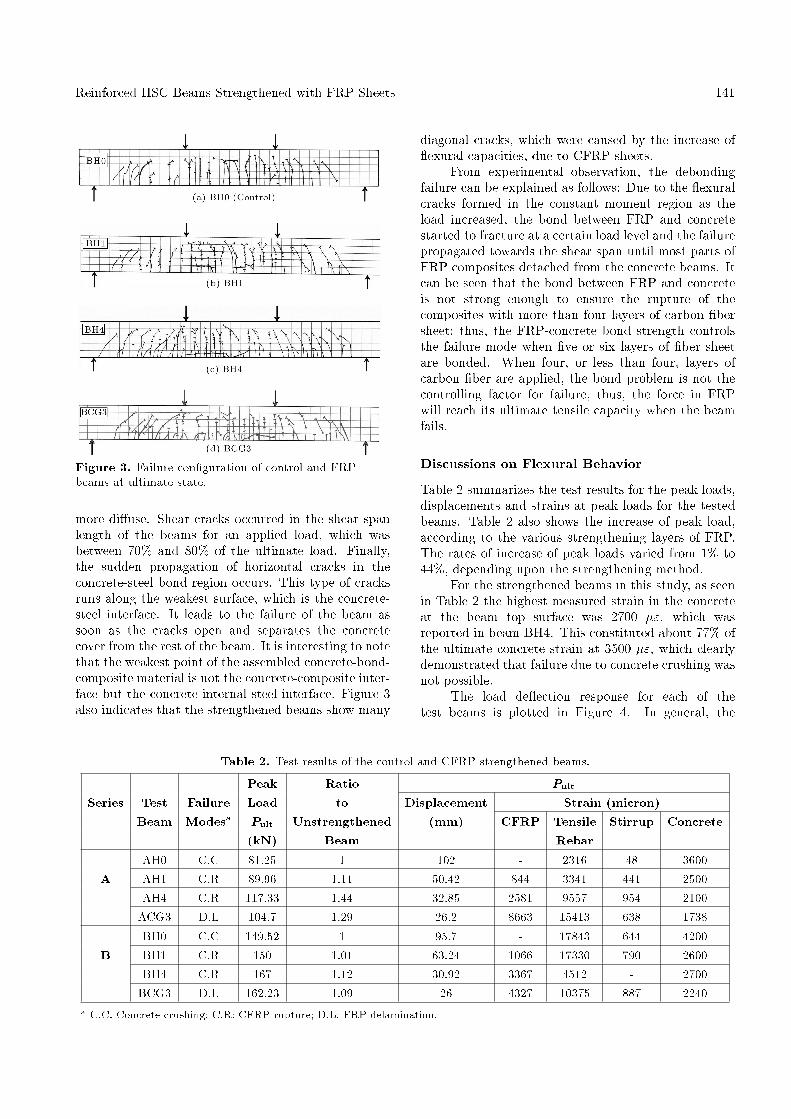
The relationship between concrete strains (measuredon the compression face at mid-span) and appliedmoments for both A and B series are plotted inFigure 8. There is a similar increase in strain for allthe beams at low moments. However, cracking of theconcrete in the tension zone results in larger incrementsof strain in the control specimens (i.e., for control beamAH0, the extreme layer of concrete compressive strainat failure is "cu = 0:0036). For these beams, concretestrain varies almost linearly with moment, after initialcracking, until the yielding of the tension steel. Fol-lowing yield, steel strain increases rapidly, with eachincrement of moment, and, �nally, the concrete crushesas the beam collapses (see Table 2). On the otherhand, the extreme compressive strain of concrete �berin the strengthened beams, with the increased numberof layers of the CFRP sheet, remains more or less linearup to failure and is not signi�cantly a�ected by concretecracking or a yielding of the tension steel. These resultsdemonstrate that the e�ect of the strengthening plateis to reduce strain in the compression �bers of theconcrete. The presence of the plate draws the neutralaxis lower in the section and, hence, places a greatervolume of concrete in compression, resulting in lowerstrain (see Table 2) and enabling a more e�cient use ofthe existing material. Thus, externally bonded CFRP
Figure 8. Moment vs concrete strain at mid-span.
plates may also be bene�cially used to reduce concretecompressive stresses, in addition to acting as additionaltensile reinforcement.
Figure 9 indicates that each curve consists ofalmost three straight lines with di�erent slopes. The�rst turning point, A, indicates the cracking of concretein the tension zone. The second turning point, B,refers to the yielding tension steel. The yielding and

Reinforced HSC Beams Strengthened with FRP Sheets 145
Figure 9. Moment-strain curves of CFRP, tensile steeland extreme top concrete �ber for beams AH4, BH4,ACG3 and BCG3 at mid-span.
maximum load (ultimate load) can be found for eachbeam from its load - strain curve.
For beams AH4 and BH4, the tensile steel andCFRP strains are essentially the same at loads belowcracking of the concrete. After cracking, the strainsin steel exceeded those of the CFRP laminate. As theload approached the yielding load for the strengthenedbeam, the strains in steel increased more rapidly thanthose in the CFRP. This is because the CFRP hadbegun to debond from the nearby cracks of the concretesurface. It was noted that tensile steels strains werealways higher than CFRP strains.
CONCLUSIONS
The major conclusions derived from this experimentalstudy are given as follows:� The results of tests performed in this study indicate
that signi�cant increase in exural strength can beachieved by bonding CFRP sheets to the tensionface of high strength reinforced concrete beams.The gain in ultimate exural strength was more
signi�cant in beams with lower steel reinforcementratios. In addition, strengthening reduced the crackwidth in beams at all load levels.
� The extreme compressive strain of concrete �ber inthe strengthened beams, with the increased numberof CFRP layers, remains more or less linear up to thefailure of the beam and is not signi�cantly a�ectedby concrete cracking or a yielding of the tensionsteel. These results demonstrate that the e�ect ofthe strengthening plate is to reduce strain in thecompression �bers of the concrete.
� Compared to a beam reinforced heavily with steelonly, beams reinforced with both steel and CFRPhave an adequate deformation capacity, in spite oftheir brittle mode of failure.
� As the amount of tensile steel reinforcement in-creases, the additional strength provided by thecarbon FRP external reinforcement decreases. Thesame amount of CFRP reinforced the exuralstrength of a lightly reinforced beam by more than44.4% (20% of balanced ratio), but only increasedthe strength of a moderately reinforced beam by11.7% (40% of balanced ratio).
REFERENCES
1. Toutanji, H., Zhao, L. and Anselm, E. \Veri�cationsof design equations of beams externally strengthenedwith FRP composites", Journal of Composites forConstruction, 10(3), pp. 254-264 (2006).
2. Oh, B.H., Cho, J.Y. and Park, D.G. \Static and fatiguebehavior of reinforced concrete beams strengthenedwith steel plates for exure", Journal of StructuralEngineering, 129(4), pp. 527-535 (2003).
3. Toutanji, H., Zhao, L. and Zhang, Y. \Flexural behav-ior of reinforced concrete beams externally strength-ened with CFRP sheets bonded with an inorganicmatrix", Journal of Engineering Structures, 28, pp.557-566 (2006).
4. Chahrour, A. and Soudki, K. \Flexural response ofreinforced concrete beams strengthened with end-anchored partially bonded carbon �ber-reinforcedpolymer strips", Journal of Composites for Construc-tion, 9(2), pp. 170-177 (2005).
5. Alagusundaramoorthy, P., Harik, I.E. and Choo, C.C.\Flexural behavior of R/C beams strengthened withcarbon �ber reinforced polymer sheets or fabric",Journal of Composites for Construction, 7(4), pp. 292-301 (2003).
6. Brena, S.F. and Marci, B.M. \E�ect of carbon-�berreinforced polymer laminate con�guration on the be-havior of strengthened reinforced concrete beams",Journal of Composites for Construction, 8(3), pp. 229-240 (2004).
7. Saadatmanesh, H. and Ehsani, M.R. \RC beamsstrengthened with GFRP plates, I: experimental

146 S.H. Hashemi, A.A. Maghsoudi and R. Rahgozar
study", Journal of Structural Engineering, 117(11),pp. 3417-3433 (1991).
8. Malek, A.M., Saadatmanesh, H. and Ehsani, M.R.\Prediction of failure load of R/C beams strengthenedwith FRP plate due to stress concentration at theplate end", ACI Structural Journal, 95(2), pp. 142-152(1998).
9. American Concrete Institue (ACI) \State-of-the-artreport on high-strength concrete", ACI Committee 363Report, Detroit (1992).
10. Fanning, P.J. and Kelly, O. \Ultimate response of RCbeams strengthened with CFRP plates", Journal ofComposites for Construction, 5(2), pp. 122-127 (2001).
11. Maghsoudi, A.A., Design for Ductility of Structures,
Shaheed Bahonar University Publications, Kerman,Iran (1996).
12. Mukhopadhyaya, P., Swamy, N. and Lynsdale, C.\Optimizing structural response of beams strength-ened with GFRP plates", Journal of Composites forConstruction, 2(2), pp. 87-95 (1998).
13. Hashemi, S.H. \Analytical and experimental study ofHSC members strengthened with CFRP", PhD Thesis,Civil Eng. Dept. of Kerman University, Iran (2007).
14. Maghsoudi, A.A. and Akbarzadeh, H. \Flexural duc-tility of HSC members", Structural Engineering andMechanics, an International Journal, 24(2), pp. 195-213 (2006).


![BEAM-COLUMN JOINTS STRENGTHENED WITH FRP SYSTEMS … in Seismic... · BEAM-COLUMN JOINTS STRENGTHENED WITH FRP SYSTEMS Ciro FAELLA Full Professor ... Paulay & Priestley [2] (model](https://static.fdocuments.us/doc/165x107/5af2d6ce7f8b9ad061913ad9/beam-column-joints-strengthened-with-frp-systems-in-seismicbeam-column-joints.jpg)