Benchmark-circuits for hardware-verification · Tamarack Processor Stop-Watch GCD Mulliplier...
12
Benchmark-Circuits for Hardware -Verification Thomas Kropf Institut f'tir Rechnerentwurf und Fehlertoleranz (Prof. D. Schmid) Universit~t Karlsruhe, Kaiserstr. 12, 76128 Karlsruhe, Germany email: [email protected] WWW: http://goethe.ira.uka.de/hvg/ Abstract. This document describes the IFIP WG10.2 hardware-verifi- cation benchmark circuits, intended for evaluating different approaches and algorithms for hardware verification. The paper presents the ratio- nale behind the circuits, describes them briefly and indicates how to get access to the verification benchmark set. 1 Introduction 1.1 Motivation and State-of-the-Art Although having many drawbacks, benchmark circuits allow a more succinct and direct comparison of different approaches for solving a certain problem. This has lead to sets of widely accepted circuits e.g. in the area of testing [1, 2] or high-level synthe- sis [3]. In the area of hardware verification, this lead e.g. to the suggestion of "interesting" circuits, like Paillet's set of seven sequential circuits [4]. One of the first efforts to pro- vide circuits for a broader community has been done by Luc Claesen for the 1990 International Workshop on Applied Formal Methods for VLSI Design [5]. The most prominent circuit evolving from this effort was the "Min_Max-Circuit". The lack of additional, generally available verification benchmark circuits got aware in the preparation of the 2nd International Conference on Theorem Provers in Circuit Design (TPCD94). The motivation to provide additional benchmark circuits together with already ongoing standardization efforts of IFIP, coordinated by JCrgen Staunstrup [6], has led to an enhanced set of circuits. Thanks to J. Staunstrup, in the meantime these circuits have become the official "IFIP WG 10.2 Hardware Verification Benchmark Circuit Set". It will be maintained and enhanced on a long term basis to promote a standardized benchmark set in the hardware verification community. For the circuits a complete and self-contained implementation is provided, done in a commercial design system [7] (leading e.g. to additional timing diagrams for clarifi- cation) as well as a clear specification using the standardized hardware description lan- guage VHDL (see Section 2.3). This puts a comparison of different verification approaches on a sound basis, since - if the given implementations are used - identical circuits are verified instead of different designs implemented in a way especially suited for a certain approach. Moreover, people are not forced to tediously design the circuits before they can be verified - the latter being the main interest of people looking into
Transcript of Benchmark-circuits for hardware-verification · Tamarack Processor Stop-Watch GCD Mulliplier...
Benchmark-Circuits for Hardware -Verification
Thomas Kropf
Institut f'tir Rechnerentwurf und Fehlertoleranz (Prof. D. Schmid) Universit~t Karlsruhe, Kaiserstr. 12, 76128 Karlsruhe, Germany
email: [email protected] WWW: http://goethe.ira.uka.de/hvg/
Abstract. This document describes the IFIP WG10.2 hardware-verifi- cation benchmark circuits, intended for evaluating different approaches and algorithms for hardware verification. The paper presents the ratio- nale behind the circuits, describes them briefly and indicates how to get access to the verification benchmark set.
1 Introduction
1.1 Motivation and State-of-the-Art
Although having many drawbacks, benchmark circuits allow a more succinct and direct comparison of different approaches for solving a certain problem. This has lead to sets of widely accepted circuits e.g. in the area of testing [1, 2] or high-level synthe- sis [3].
In the area of hardware verification, this lead e.g. to the suggestion of "interesting" circuits, like Paillet's set of seven sequential circuits [4]. One of the first efforts to pro- vide circuits for a broader community has been done by Luc Claesen for the 1990 International Workshop on Applied Formal Methods for VLSI Design [5]. The most prominent circuit evolving from this effort was the "Min_Max-Circuit".
The lack of additional, generally available verification benchmark circuits got aware in the preparation of the 2nd International Conference on Theorem Provers in Circuit Design (TPCD94). The motivation to provide additional benchmark circuits together with already ongoing standardization efforts of IFIP, coordinated by JCrgen Staunstrup [6], has led to an enhanced set of circuits. Thanks to J. Staunstrup, in the meantime these circuits have become the official "IFIP WG 10.2 Hardware Verification Benchmark Circuit Set". It will be maintained and enhanced on a long term basis to promote a standardized benchmark set in the hardware verification community.
For the circuits a complete and self-contained implementation is provided, done in a commercial design system [7] (leading e.g. to additional timing diagrams for clarifi- cation) as well as a clear specification using the standardized hardware description lan- guage VHDL (see Section 2.3). This puts a comparison of different verification approaches on a sound basis, since - if the given implementations are used - identical circuits are verified instead of different designs implemented in a way especially suited for a certain approach. Moreover, people are not forced to tediously design the circuits before they can be verified - the latter being the main interest of people looking into

these circuits. Naturally, when dealing with formal synthesis, the implementations pro- vided here are less interesting and the specifications are the main thing to deal with.
1.2 Requirements for Verification Benchmark Circuits
A set of verification benchmark circuits has to provide easily usable circuits to evalu- ate and to compare different approaches to hardware verification. This comprises:
�9 availability via the World Wide Web and anonymous tip,
�9 a high degree of diversity with regard to the underlying verification task (see Section 2.4),
~ circuit descriptions without ambiguity, which are succinct and self-contained and
�9 circuits which span a wide range from introductory examples to real verification challenges [6].
2 The Benchmark Circuits
2.1 Scope Currently, there is the set of benchmark circuits given in table 2-1. The main sources for these circuits have been the previous IFIP benchmark set [6] and various textbooks on circuit design.
Circuit Name Short Circuit Description
Single Pulser cuts input pulses to a ftxed length.
Traffic Light Controller simplified controller for a traffic light
N-bit Adder sum of two bitvectors of length N
Min_Max the mean value of incoming integers
Black-Jack Dealer the dealer's hand of a card game
access to shared resotaxes for N clients Arbiter
Rollback Chip
Tamarack Processor
Stop-Watch
GCD
Mulliplier
Divide"
FIFO
Assotiafive Memory
coprocessor for distributed simul,atlon
simplified microprocessor
digital stopwatch with3 digits and 2buttous
Greatest Common Divisor
N-bit Mullipfier
N-bit Divider
asynchronous FIFO queue with N places
simple assotialive N x M moru3ry
Table 2-1: Current Benchmark Circuits
Circuit Name Short Circuit Description
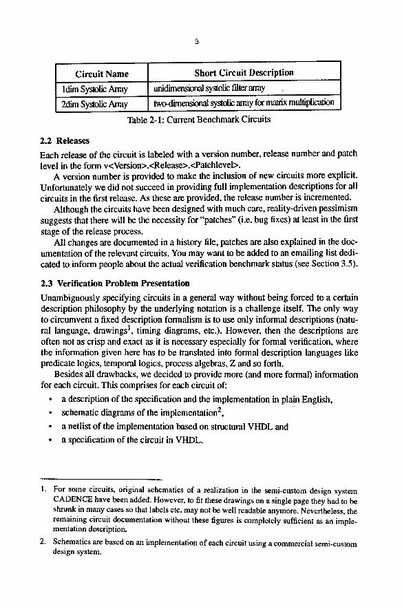
ldim Systolic Away unidimensional systolic fdter array
2dim Systolic Array two-dimensional systolic army for malrix multiplication
Table 2-1: Current Benchmark Circuits
2.2 Releases
Each release of the circuit is labeled with a version number, release number and patch level in the form v<Version>.<Release>.<Patchlevel>.
A version number is provided to make the inclusion of new circuits more explicit. Unfortunately we did not succeed in providing full implementation descriptions for all circuits in the first release. As these are provided, the release number is incremented.
Although the circuits have been designed with much care, reality-driven pessimism suggests that there will be the necessity for "patches" (i.e. bug fixes) at least in the first stage of the release process.
All changes are documented in a history file, patches are also explained in the doc- umentation of the relevant circuits. You may want to be added to an emailing list dedi- cated to inform people about the actual verification benchmark status (see Section 3.5).
2.3 Verification Problem Presentation
Unambiguously specifying circuits in a general way without being forced to a certain description philosophy by the underlying notation is a challenge itself. The only way to circumvent a fixed description formalism is to use only informal descriptions (natu- ral language, drawings 1, timing diagrams, etc.). However, then the descriptions are often not as crisp and exact as it is necessary especially for formal verification, where the information given here has to be Iranslated into formal description languages like predicate logics, temporal logics, process algebras, Z and so forth.
Besides all drawbacks, we decided to provide more (and more formal) information for each circuit. This comprises for each circuit of:
�9 a description of the specification and the implementation in plain English,
�9 schematic diagrams of the implementation 2,
�9 a netlist of the implementation based on structural VHDL and
�9 a specification of the circuit in VHDL.
1. For some circuits, original schematics of a realization in the semi-custom design system CADENCE have been added. However, to fit these drawings on a single page they had to be shrunk in many cases so that labels etc. may not be well readable anymore. Nevertheless, the remaining circuit documentation without these figures is completely sufficient as an imple- mentation description.
2. Schematics are based on an implementation of each circuit using a commercial semi-costom design system.
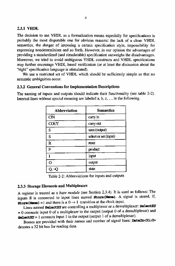
2.3.1 VHDL
The decision to use VHDL as a formalization means especially for specifications is probably the most disputable one for obvious reasons: the lack of a clean VHDL semantics, the danger of imposing a certain specification style, impossibility for expressing nondeterminism and so forth. However, in our opinion the advantages of providing a standardized (and simulatable) specification outweighs the disadvantages. Moreover, we tried to avoid ambiguous VHDL constructs and VHDL specifications may further encourage VHDL based verification (or at least the discussion about the "right" specification language is stimulated).
We use a restricted set of VHDL which should be sufficiently simple so that no semantic ambiguities occur.
2.3.2 General Conventions for Implementation Descriptions
The naming of inputs and outputs should indicate their functionality (see table 2-2). Internal lines without special meaning are labeled a, b, c . . . . in the following.
Abbreviation Semantics
CIN carry in
COUT carry out
S sum (output)
S select or set (input)
R reset
p product
I input
O output
Q,--Q state
Table 2-2: Abbreviations for inputs and outputs
2.3.3 Storage Elements and Multiplexers
A register is treated as a base module (see Section 2.3.4). It is used as follows: The inputs S is connected to input lines named ~ . o z ' r A signal is stored, if, Beoz~(Hum) =1 and there is a 0 --> 1 transition at the clock input.
Lines named ,~jd.cce.XY are controlling a multiplexer or a demultiplexer: se.l~-'r.xY = 0 connects input 0 of a multiplexer to the output (output 0 of a demultiplexer) and ~d.ec, ex~ = 1 connects input 1 to the output (output 1 of a demultiplexer).
Busses are provided with their names and number of signal lines: l~ez.~a<3:t:0>
denotes a 32 bit bus for reading data.
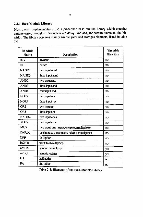
2.3.4 Base Module Library
Most circuit implementations use a predefined base module library which contains parameterized modules. Parameters are delay time and, for certain elements, the bit- width. The library contains mainly simple gates and storages elements, listed in table 2-3.
Module Variable Name Description Bitwidth
INV inverter no
BUF buffer no
NAND2 two input nand no
NAND3 three input nard no
AND2 two input and no
AND3 three input and no
AND4 four input and no
NOR2 two input nor no
NOR3 three input nor no
OR2 two input or no
OR3 three input or no
NXOP,2 two input equal no
XOR2 two input exor no
MUX two input, one output, one select multiplexer no
DMUX one input two output one select demultiplexer no
DFF D-flipflop no
RSFFR resetable RS-flipflop no
nMUX genetic multiplexer yes
nREG generic register yes
HA half adder no
FA full adder no
Table 2-3: Elements of the Base Module Library
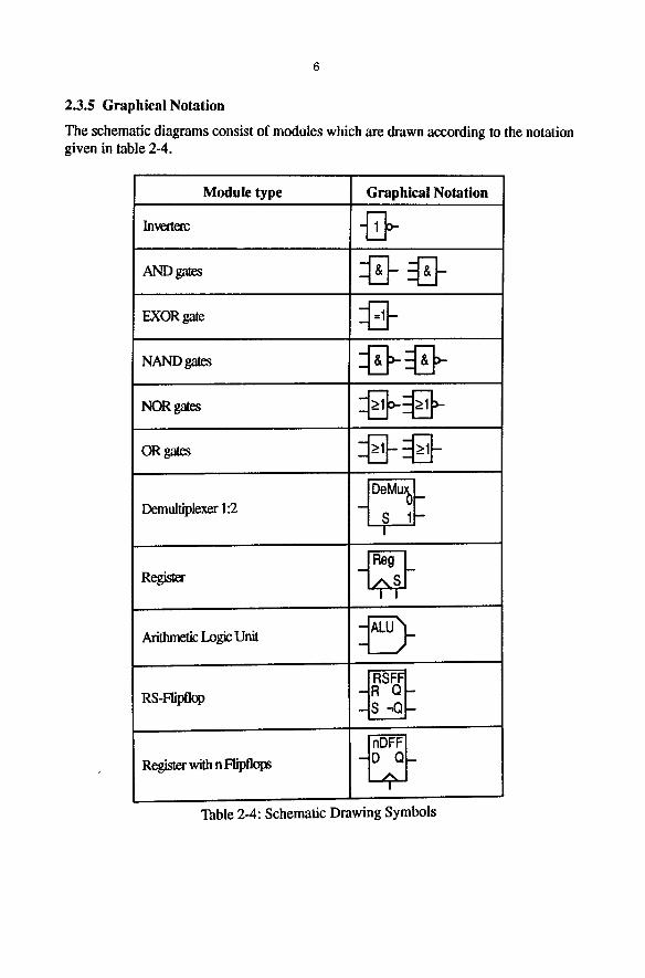
2.3.5 Graphical Notation
The schematic diagrams consist of modules which are drawn according to the notation given in table 2-4.
Module type Graphical Notation
Inve~r - ~
EXOR gale
OR gates
Demultiplexer 1:2
Register
Arithmetic Logic Unit
RS-Flipflop
Register with n Flipflops
DeMu~ _ n
S 1 - !
RSFF - R Q - - S - Q -
nDFF -D Q-
I
Table 2-4: Schematic Drawing Symbols

2.4 Classification of the VerificationTasks and the Circuits
2.4.1 Verification Tasks
There are mainly three verification tasks to be distinguished when talking about hard- ware verification:
1. verifying that a circuit specification is what it should be,
2. verifying that a given implementation behaves identically to a given specification and
3. verifying important (e.g. safety critical) properties of a given implementation.
According to [6], the first is called requirements capture, the second implementation verification and the third design verification.
The three tasks are often expressed in terms of a specification S and an implemen- tation I, where a complete verification denotes some form of equivalence between S and I ( S = I , S -- I , S r I ) and a partial verification denotes some form of implica- tion (I=~ S , I D S , II--S):
The first task is a partial verification (with S describing properties of the circuit specification and I being the circuit specification), the second is a complete verification (with S being the specification and I being the implementation) and the third is again a partial verification (with S describing the properties of the circuit implementation and I being the circuit implementation).
It is to be noted that if e.g. exact computation times are not stated in a specification then we have to cope with a verification problem of the third kind, since in that case an equivalence proof is not possible.
All three verification tasks are covered by the benchmark circuits.
2.4.2 Circuit Classification
Every classification scheme has its drawbacks, but we found the following circuit properties especially useful for classification purposes.
A circuit may be classified in several dimensions as depicted in table 2-5. Most of the criteria are self-explaining, besides complexity. In the area of testing usually the number of internal lines is directly used as a complexity measure [1, 2], motivated by the designated application of the circuits: test pattern generation. Using a classical stuck-at fault model, the set of faults to be treated equals the number of internal lines. Hence a circuit s713 denotes a sequential circuit with 713 internal lines [2].
In the area of hardware verification a similar complexity measure is not as obvious (at least we did not found any meaningful). Hence we use the coarse measure, pro- posed by J. Staunstrup: an example is either introductory, illustrative or a real chal- lenge [6].
The abbreviations given in table 2-5 may be used to characterize each circuit using the following "signature":
<Name>:<Spec>-<Imp>.<S ync>.<Hier>.<Det>.<Gener>.<Type>.Compl>
A circuit ~CD. a - r . s . h . d . g .ra. 5. denotes the Greatest Common Divisor circuit, which has a specification on algorithmic level and an implementation on register-trans-
Classification Criterion Value Set
Abslmclion level
system (s) algorithmic (a) registea'-Iransfer (r) gate (g) transistor (t)
synchronous (s) Synchronicity of the implementation asynchronous (a)
combinational (c)
hierachical (11) Hierarchy of the implementation flat (f)
deterministic (d) nondeterministic (n)
generic (g) Genericity concrete with (optional) bitwidth n (ca)
controller (c) Type dalapath (d)
mixed (both) (m)
introductory (i) Complexity standard illuslrative (s)
challenge (c)
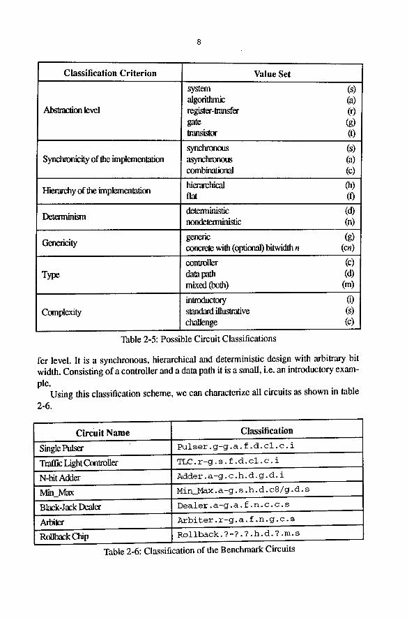
Table 2-5: Possible Circuit Classifications
fer level. It is a synchronous, hierarchical and deterministic design with arbitrary bit width. Consisting of a controller and a data path it is a small, i.e. an introductory exam- ple.
Using this classification scheme, we can characterize all circuits as shown in table 2-6.
Circuit Name Classification
Sin#Purr
Traffic Light Con~o~e~
N-bit Adder
lV~n lVlax
Black-Jack Dealer
Arbiter
Rollback Chip
Pulser.g-g.a.f.d.cl.c.i
TLC.r-g.s.f.d.cl.c.i
Adder .a-g .c.h.d. g .d. i
Min_Max. a-g. s. h. d. c8/g .d. s
Dealer.a-g.a.f.n.c.c.s
Arbiter.r-g.a.f.n.g.c.s
Rollback. ?-?. ? �9 h.d. ? .m. s
Table 2-6: Classification of the Benchmark Circuits
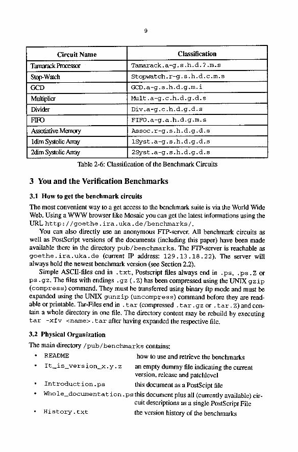
Circuit Name Classification
Tamarack Process3r T a m a r a c k . a - g . s . h . d . ? .m. s
S~Wmch Stopwatch. r-g. s. h. d. c.m. s
GCD GCD. a-g. s .h.d.g.m. i
MMfipli~ Mult. a-g. c .h.d.g.d. s
Divider Div. a-g. c. h. d. g. d. s
FIFO .a-g. a .h.d. g .m. s
Assofafive Memory Assoc. r-g. s. h. d. g. d. s
Id~n Systolic Away ISyst. a-g. s. h. d. g. d. s
2dim Systolic Away 2Syst. a-g. s. h. d. g. d. s
Table 2-6: Classification of the Benchmark Circuits
3 You and the Verification Benchmarks
3.1 How to get the benchmark circuits
The most convenient way to a get access to the benchmark suite is via the World Wide Web. Using a WWW browser like Mosaic you can get the latest informations using the URL http : //goethe. ira. uka. de/benchmarks/.
You can also directly use an anonymous FTP-server. All benchmark circuits as well as PostScript versions of the documents (including this paper) have been made available there in the directory p u b / b e n c h m a r k s . The Fl'P-server is reachable as g o e t h e . i r a . u k a . d e (current IP address: 1 2 9 . 1 3 . 1 8 . 2 2 ) . The server will always hold the newest benchmark version (see Section 2.2).
Simple ASCII-files end in . t x t , Postscript files always end in . p s , . p s . z or p s . gz . The files with endings . gz (. Z) has been compressed using the UNIX g z i p ( c o m p r e s s ) command. They must be transferred using binary ftp mode and must be expanded using the UNIX gun z i p ( u n c o m p r e s s) command before they are read- able or printable. Tar-Files end in . t a r (compressed . t a r . gz o r . t a r . Z) and con- tain a whole directory in one file. The directory content may be rebuild by executing t a r - x f v <name> . t a r after having expanded the respective file.
3.2 Physical Organization
The main d i r e c t o r y / p u b / b e n c h m a r k s contains:
�9 README how to use and retrieve the benchmarks
�9 I t i s v e r s i o n _ x . y , z an empty dummy file indicating the current version, release and patchlevel
�9 I n t r o d u c t i o n . p s this document as a PostScipt file
�9 Whole d o c u m e n t a t i o n . p s this document plus all (currently available) cir- cuit descriptions as a single PostScript File
�9 H i s t o r y . t x t the version history of the benchmarks

10
�9 Library.vhdl
�9 <circuit>
�9 documentation
�9 pending
the base module library (see Section 2.3.4)
a directory for each benchmark circuit
a directory containing the whole documenta- tion in its original FrameMaker 4 format (for those who want to get the document "sources")
a directory containing circuits which will be probably be included in future releases of the benchmark circuits.l
Each circuit directory < c i r c u i t > contains:
�9 < c i r c u i t > . p s a PostScript file describing the circuit
�9 <c i r c u i t > _ s c h e m . p s a PostScript file containing schematic diagrams of the implementations (not for all circuits)
�9 W A V E < c i r c u i t > . p s a PostScript file containing timing diagrams of the circuit implementation (not for all circuits) 2
�9 < c i r c u i t > . v h d l a VHDL specification and a (structural) VHDL implementation of the circuits
3.3 Using the benchmarks
You can use the benchmark circuits in any way which suits your needs. Especially when specifying the problems, you are in no way obliged to use VHDL. The VHDL specifications are mainly provided to clarify the intended proof goals.
However, if for example, you use an implementation completely different from the ones given here (e.g. a simplified version) you should state this clearly whenever you refer to the circuits provided here.
Some of the circuits have been designed hierarchically. If you are flattening the cir- cuits in order to verify them, you should state this also.
3.4 Please Contact us i f . . .
Please contact us if you have any problems, especially
�9 if you have questions of any kind concerning the benchmarks,
�9 if you have comments or proposal for changes, additions or even new circuits,
�9 if you can provide "better" implementations for the circuits,
�9 if you have problems in printing the PostScript files,
�9 if you detect errors, inconsistencies or ambiguities, which should be fixed or
�9 if you have problems in accessing the files.
1.
2.
For these circuits the documentation may be incomplete~ inconsistent or completely missing.
Note that this file resulted from a simulation of the VHDL sources <circuit>.vhdl. There may be additional simulations in the documentation of the respective circuit description. However, the latter have been the result of simulating the CADENCE designs of the circuits and there may be minor differences in the waveforms with regard to timing etc.

The easiest way is to send a brief email to Thomas Kropf or to Jergen Staunstrup (kropf@ informat ik. uni-karlsruhe, de, j st@id, dth. dk).
3.5 Email list
To inform people about the latest release and patches of the benchmark circuits, we do maintain an informal emailing list. If you want to be added (or deleted) from this list, send a short note to kropfOinformat ik. uni-karlsruhe, de.
4 Present and Future Activity
4.1 The Present
At the moment, we are busy simply with completing all proposed circuits and - - prob- ably - - by making the current set consistent.
4.2 The Future
The current set of circuits falls short of asynchronous verification examples. Moreover protocol verification problems are not covered, which may also be viewed at as impor- tant sub-aspects of circuit verification. To cover lower description levels, we also would like to add some switch-level or transistor level verification examples.
There is still a lack of "challenging" verification examples, i.e. circuits which are either of significant size or which reflect "real" commercial designs. As one of these circuits, we will probably provide a large RISC-processor: the DLX of Patterson and Hennesy [8].
4.3 Acknowledgments
We like to thank the following people, and documentation:
�9 Ralf Reetz
�9 Hans-Peter Eich
�9 Ramayya Kumar
�9 Klaus Schneider
Jergen Staunstrup,
the Authors of TPTP
who have helped in creating this benchmark set
for significant ideas and contributions like the parameterized base module library,
for implementing all circuits in a commercial design system and for providing all the figures and timing diagrams,
for many valuable comments,
for pointing out interesting verification prob- lems,
for supporting this activity via IFIP and sug- gesting the IFIP circuits and
for the excellent documentation of their theo- rem proving benchmarks [9], which helped us in structuring this document

12
5 Literature
[1] F. Brglez, P. Pownall, and R. Hum. Accelerating ATPG and fault grading via testability analysis. In International Symposium on Circuits and Systems, 1985.
[2] F. Brglez, D. Bryan, and K. Kozminski. Combinational profiles of sequential benchmark circuits. In International Symposium'on Circuits and Systems, May 1989.
[3] R. Vemuri, J. Roy, P. Mamtora, and N. Kumar. Benchmarks for high-level synthesis. Technical Report ECE-DDE-91-11, Laboratory for Digital Design Environments, ECE Dept., University of Cincinnati, Ohio, USA, November 1991.
[4] J.-L. Paillet. Un Modele de Fonctions Sequentielles pour la Verification Formelle de Systemes Digitaux. Technical Report 546, IMAG-ARTEMIS, Grenoble, June 1985.
L. Claesen, editor. International Workshop on Applied Formal Methods for VLSI Design, Leuven, Belgium, 1990.
J. Staunstrup. IFIP WG 10.2 collection of circuit verification examples, November 1993.
CADENCE Design Framework II version 4.2a. Reference Manual, February 1992.
J.L. Hennessy and D.A. Patterson. Computer Architecture: A quantitative Approach. Morgan Kaufmann Publishers Inc., San Mateo, CA, USA, 1990.
C. Suttner, G. Sutcliff, and T. Yemenis. The TPTP (Thousands of Problems for Theorem Provers) Problem Library. TU Muenchen, Germany and James Cook University, Australia, via anonymous ftp flop.informatik.tu-muenchen.de, tptpvl.O.O edition, 1993.
[5]
[61
[7]
[8]
[9]