Benchmark 3.0 Dual-Fuel Series Gas Fired Low NOx ... -...
134
REVISED OCTOBER 4, 2012 GF-117 OMM-0039_0C Benchmark 3.0 Dual-Fuel Low NOx Boiler USER MANUAL Applicable to Serial Numbers G-11-0708 and above Installation, Operation & Maintenance Instructions Benchmark 3.0 Dual-Fuel Series Gas Fired Low NOx Boiler System Natural Gas and Propane Fired, Condensing, Forced Draft Hot Water Boiler 3,000,000 BTU/H Input
Transcript of Benchmark 3.0 Dual-Fuel Series Gas Fired Low NOx ... -...

REVISED OCTOBER 4, 2012
GF-117 OMM-0039_0C
Benchmark 3.0 Dual-Fuel Low NOx Boiler USER MANUAL
Applicable to Serial Numbers G-11-0708 and above
Installation, Operation
& Maintenance Instructions
Benchmark 3.0 Dual-Fuel Series Gas Fired Low NOx Boiler System Natural Gas and Propane Fired, Condensing, Forced Draft Hot Water Boiler 3,000,000 BTU/H Input

Printed in U.S.A.
Telephone Support Direct to AERCO Technical Support (8 to 5 pm EST, Monday through Friday): 1-800-526-0288
AERCO International, Inc. 100 Oritani Drive Blauvelt, NY 10913 www.aerco,com © AERCO International, Inc., 2011
The information contained in this installation, operation and maintenance manual is subject to change without notice from AERCO International, Inc. AERCO makes no warranty of any kind with respect to this material, including but not limited to implied warranties of merchantability and fitness for a particular application. AERCO International is not liable for errors appearing in this manual. Nor for incidental or consequential damages occurring in connection with the furnishing, performance, or use of this material.

CONTENTS
i
GF-117 - AERCO BENCHMARK 3.0 DUAL-FUEL LOW NOx BOILER Operating & Maintenance Instructions
FOREWORD A
Chapter 1 – SAFETY PRECAUTIONS 1-1 Para. Subject Page 1-1 Warnings & Cautions 1-1 1-2 Emergency Shutdown 1-2
Para. Subject Page 1-3 Prolonged Shutdown 1-2
Chapter 2 – INSTALLATION 2-1
Para. Subject Page 2.1 Introduction 2-1 2.2 Receiving the Unit 2-1 2.3 Unpacking 2-1 2.4 Site Preparation 2-1 2.5 Supply and Return Piping 2-3 2.6 Condensate Drains 2-3 2.7 Gas Supply Piping 2-5 2.8 AC Electrical Power Wiring 2-6
Para. Subject Page 2.9 Modes of Operation and Field
Control Wiring 2-7
2.10 I/O Box Connections 2-9 2.11 Auxiliary Relay Contacts 2-11 2.12 Flue Gas Vent Installation 2-11 2.13 Combustion Air 2-11
Chapter 3 – CONTROL PANEL OPERATING PROCEDURES 3-1 Para. Subject Page 3.1 Introduction 3-1 3.2 Control Panel Description 3-1 3.3 Control Panel Menus 3-4 3.4 Operating Menu 3-5 3.5 Setup Menu 3-5
Para. Subject Page 3.6 Configuration Menu 3-6 3.7 Tuning Menu 3-8 3.8 Combustion Cal. Menu 3-8 3.9 Start Sequence 3-8 3.10 Start/Stop Levels 3-10
Chapter 4 – INITIAL START-UP 4-1 Para. Subject Page 4.1 Initial Startup Requirements 4-1 4.2 Tools and Instruments for
Combustion Calibration 4-1
4.3 Natural Gas Combustion Calibration
4-2
Para. Subject Page 4.4 Propane Combustion Calibration 4-6 4.4 Unit Reassembly 4-9 4.5 Over-Temperature Limit Switch 4-9

CONTENTS
ii
Chapter 5 – MODE OF OPERATION 5-1 Para. Subject Page 5.1 Introduction 5-1 5.2 Indoor/Outdoor Reset Mode 5-1 5.3 Constant Setpoint Mode 5-2 5.4 Remote Setpoint Mode 5-2 5.5 Direct Drive Modes 5-3
Para. Subject Page 5.6 Boiler Management System
(BMS) 5-4
5.7 Combination Control System (CCS)
5-5
Chapter 6 – SAFETY DEVICE TESTING PROCEDURES 6-1 Para. Subject Page 6.1 Testing of Safety Devices 6-1 6.2 Natural Gas Low Gas Pressure
Switch Test 6-1
6.3 Propane Low Gas Pressure Switch Test
6-2
6.4 Natural Gas High Gas Pressure Switch Test
6-2
6.5 Propane High Gas Pressure Switch Test
6-2
6.6 Low Water Level Fault Test 6-3 6.7 Water Temperature Fault Test 6-3
Para. Subject Page 6.8 Interlock Tests 6-4 6.9 Flame Fault Test 6-4 6.10 Air Flow Fault Test 6-5 6.11 SSOV Proof of Closure Switch 6-6 6.12 Purge Switch Open During
Purge 6-6
6.13 Ignition Switch Open During Ignition
6-7
6.14 Safety Pressure Relief Valve Test
6-7
Chapter 7 – MAINTENANCE REQUIREMENTS 7-1 Para. Subject Page 7.1 Maintenance Schedule 7-1 7.2 Spark Ignitor 7-1 7.3 Flame Detector 7-3 7.4 Combustion Calibration 7-3 7.5 Safety Device Testing 7-3 7.6 Burner Inspection 7-3
Para. Subject Page 7.7 Condensate Drain Trap 7-4 7.8 Shutting the Boiler Down For An
Extended Period of Time 7-5
7.9 Placing The Boiler Back In Service After A Prolonged Shutdown
7-5
Chapter 8 – TROUBLESHOOTING GUIDE 8-1 Para. Subject Page 8.1 Introduction 8-1
Para. Subject Page

CONTENTS
iii
Chapter 9 - RS232 COMMUNICATION 9-1 Para. Subject Page 9.1 Introduction 9-1 9-2 RS232 Communication Setup 9-1
Para. Subject Page 9-3 Menu Processing Utilizing
RS232 Communication 9-1
9-4 Data Logging 9-2
APPENDICES App Subject Page A Boiler Menu Item Descriptions A-1 B Startup, Status and Fault
Messages B-1
C Temperature Sensor Resistance Chart
C-1
D Indoor/Outdoor Reset Ratio Charts
D-1
E Boiler Default Settings E-1
App Subject Page F Dimensional and Part Drawings F-1 G Piping Drawings G-1 H Wiring Schematics H-1 I Recommended Periodic Testing
Checklist I-1
J Benchmark Control Panel Views J-1 K Benchmark 3.0 Dual-Fuel
Switchover Instructions K-1
L Recommended Spare Parts L-1

FOREWORD
A
Foreword The AERCO Benchmark 3.0 Dual-Fuel Boiler is a modulating unit. It represents a true industry advance that meets the needs of today's energy and environmental concerns. Designed for application in any closed loop hydronic system, the Benchmark's modulating capability relates energy input directly to fluctuating system loads. The Benchmark 3.0, with its 15:1 turn down ratio and condensing capability, provides extremely high efficiencies and makes it ideally suited for modern low temperature, as well as, conventional heating systems. The Benchmark 3.0 operates at inputs ranging from 200,000 BTU/hr. to 3,000,000 BTU/hr. The output of the boiler is a function of the unit’s firing rate and return water temperature. Output ranges from 198,000 BTU/hr. to 2,900,000 BTU/hr., depending on operating conditions. When installed and operated on natural gas in accordance with this Instruction Manual, the Benchmark 3.0 Boiler complies with the NOx emission standards outlined in:
• South Coast Air Quality Management District (SCAQMD), Rule 1146.1
Whether used in singular or modular arrangements, the Benchmark 3.0 offers the maximum flexibility in venting with minimum installation space requirements. The Benchmark's advanced electronics are available in several selectable modes of operation offering the most efficient operating methods and energy management system integration. For service or parts, contact your local sales representative or AERCO INTERNATIONAL. NAME: ORGANIZATION:
ADDRESS: TELEPHONE: INSTALLATION DATE: _____________________________________________

SAFETY PRECAUTIONS
1-1
CHAPTER 1 SAFETY PRECAUTIONS
1.1 WARNINGS & CAUTIONS Installers and operating personnel MUST, at all times, observe all safety regulations. The following warnings and cautions are general and must be given the same attention as specific precautions included in these instructions. In addition to all the requirements included in this AERCO Instruction Manual, the installation of units MUST conform with local building codes, or, in the absence of local codes, ANSI Z223.1 (National Fuel Gas Code Publication No. NFPA-54). Where ASME CSD-1 is required by local jurisdiction, the installation must conform to CSD-1.
Where applicable, the equipment shall be installed in accordance with the current Installation Code for Gas Burning Appliances and Equipment, CSA B149.1, and applicable Provincial regulations for the class; which should be carefully followed in all cases. Authorities having jurisdiction should be consulted before installations are made.
IMPORTANT This Instruction Manual is an integral part of the product and must be maintained in legible condition. It must be given to the user by the installer and kept in a safe place for future reference.
WARNINGS MUST BE OBSERVED TO PREVENT SERIOUS INJURY.
WARNING BEFORE ATTEMPTING TO PER-FORM ANY MAINTENANCE ON THE UNIT, SHUT OFF ALL GAS AND ELECTRICAL INPUTS TO THE UNIT.
WARNING THE EXHAUST VENT PIPE OF THE UNIT OPERATES UNDER A POSITIVE PRESSURE AND THERE-FORE MUST BE COMPLETELY SEALED TO PREVENT LEAKAGE OF COMBUSTION PRODUCTS INTO LIVING SPACES.
WARNING A DOUBLE-POLE SWITCH MUST BE INSTALLED ON THE ELECTRICAL SUPPLY LINE OF THE UNIT. THE SWITCH MUST BE INSTALLED IN AN EASILY ACCESSIBLE POSITION TO QUICKLY AND SAFELY DIS-CONNECT ELECTRICAL SERVICE. DO NOT AFFIX SWITCH TO UNIT SHEET METAL ENCLOSURES.
WARNING DO NOT USE MATCHES, CANDLES, FLAMES, OR OTHER SOURCES OF IGNITION TO CHECK FOR GAS LEAKS.
WARNING! FLUIDS UNDER PRESSURE MAY CAUSE INJURY TO PERSONNEL OR DAMAGE TO EQUIPMENT WHEN RELEASED. BE SURE TO SHUT OFF ALL INCOMING AND OUTGOING WATER SHUTOFF VALVES. CAREFULLY DECREASE ALL TRAPPED PRESSURES TO ZERO BEFORE PERFORMING MAINTENANCE.
WARNING ELECTRICAL VOLTAGES UP TO 460 VAC MAY BE USED IN THIS EQUIPMENT. THEREFORE THE COVER ON THE UNIT’S POWER BOX (LOCATED BEHIND THE FRONT PANEL DOOR) MUST BE INSTALLED AT ALL TIMES, EXCEPT DURING MAINTENANCE AND SERVICING.
CAUTIONS Must be observed to prevent equip-ment damage or loss of operating effectiveness.

SAFETY PRECAUTIONS
1-2
CAUTION Many soaps used for gas pipe leak testing are corrosive to metals. The piping must be rinsed thoroughly with clean water after leak checks have been completed.
CAUTION DO NOT use this boiler if any part has been under water. Call a qualified service technician to inspect and replace any part that has been under water.
1.2 EMERGENCY SHUTDOWN If overheating occurs or the gas supply fails to shut off, close the manual gas shutoff valve (Figure 1-1) located external to the unit.
IMPORTANT The Installer must identify and indicate the location of the emergency shutdown manual gas valve to operating personnel.
MANUAL GAS SHUTOFF VALVE
VALVE OPEN VALVE CLOSED
Figure 1-1 Manual Gas Shutoff Valve
1.3 PROLONGED SHUTDOWN After prolonged shutdown, it is recommended that the startup procedures in Chapter 4 and the safety device test procedures in Chapter 6 of this manual be performed, to verify all system-operating parameters. If there is an emergency, turn off the electrical power supply to the AERCO boiler and close the manual gas valve located upstream the unit. The installer is to identify the emergency shut-off device.

INSTALLATION
2-1
CHAPTER 2 INSTALLATION
2.1 INTRODUCTION This Chapter provides the descriptions and procedures necessary to unpack, inspect and install the AERCO Benchmark 3.0 Dual-Fuel Boiler. Brief descriptions are also provided for each available mode of operation. Detailed procedures for implementing these modes are provided in Chapter 5.
2.2 RECEIVING THE UNIT Each Benchmark 3.0 Dual-Fuel System is shipped as a single crated unit. The shipping weight is approximately 2,170 pounds. The unit must be moved with the proper rigging equipment for safety and to avoid equipment damage. The unit should be completely inspected for evidence of shipping damage and shipment completeness at the time of receipt from the carrier and before the bill of lading is signed.
NOTE AERCO is not responsible for lost or damaged freight.
Each unit has a Tip-N-Tell indicator on the outside of the crate. This indicates if the unit has been turned on its side during shipment. If the Tip-N-Tell indicator is tripped, do not sign for the shipment. Note the information on the carrier’s paperwork and request a freight claim and inspection by a claims adjuster before proceeding. Any other visual damage to the packaging materials should also be made clear to the delivering carrier.
2.3 UNPACKING Carefully unpack the unit taking care not to damage the unit enclosure when cutting away packaging materials
A close inspection of the unit should be made to ensure that there is no evidence of damage not indicated by the Tip-N-Tell indicator. The freight carrier should be notified immediately if any damage is detected.
The following accessories come standard with each unit and are either packed separately within the unit’s packing container or are factory installed on the boiler:
• Pressure/Temperature Gauge • Spare Ignitor-Injector • Spare Flame Detector • ASME Pressure Relief Valve • Condensate Drain Trap • 2” Gas Supply Shutoff Valve When ordered, optional accessories may be packed separately, packed within the boiler shipping container, or may be installed on the boiler. Any standard or optional accessories shipped loose should be identified and stored in a safe place until ready for installation or use.
2.4 SITE PREPARATION Ensure that the site selected for installation of the Benchmark 3.0 Dual Fuel Boiler includes:
• Access to AC Input Power corresponding to the ordered power configuration. The available power configurations are: • 208 VAC, 3-Phase, 60 Hz @ 20 A • 460 VAC, 3-Phase, 60 Hz @ 15 A
• Access to Natural Gas line at a static pressure between 5.7” W.C.(min) and 2 psi (max) for Standard (FM) option
• Access to Natural Gas line at a static pressure between 6.5” W.C. (min.) and 2 psi (max.) for IRI option
• Access to Propane Gas at a static pressure between 3.5” W.C. (min.) and 2 psi (max.) for both Standard (FM) and IRI options
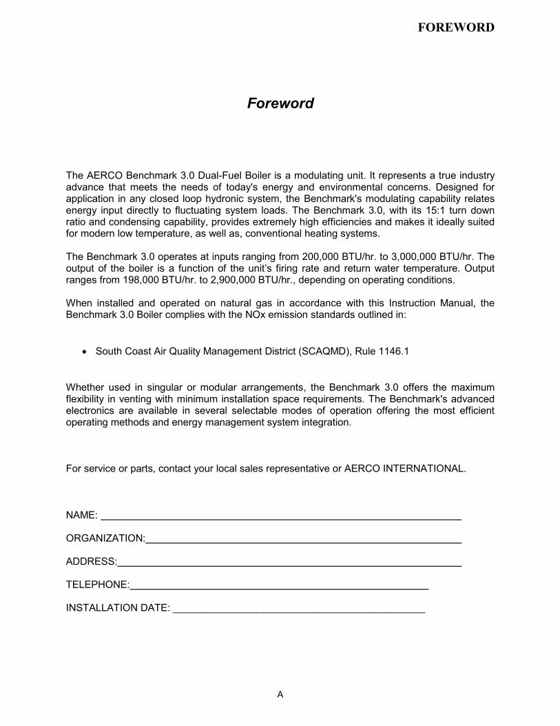
2.4.1 Installation Clearances The unit must be installed with the prescribed clearances for service as shown in Figure 2-1. The minimum clearance dimensions, required by AERCO, are listed below. However, if Local Building Codes require additional clearances, these codes shall supersede AERCO’s requirements. Minimum acceptable clearances required are: • Sides: 24 inches • Front : 24 inches • Rear: 43 inches • Top: 18 inches All gas piping, water piping and electrical conduit or cable must be arranged so that they do not interfere with the removal of any panels, or inhibit service or maintenance of the unit.
INSTALLATION
2-2
43"
24"
24"
24"
4" HIGH PAD
REAR FRONT
77" 18"
101"
79"
Figure 2-1 Benchmark 3.0 Dual Fuel Boiler Clearances
WARNING KEEP THE UNIT AREA CLEAR AND FREE FROM ALL COMBUSTIBLE MATERIALS AND FLAMMABLE VAPORS OR LIQUIDS.
CAUTION While packaged in the shipping container, the boiler must be moved by pallet jack or forklift from the FRONT ONLY.
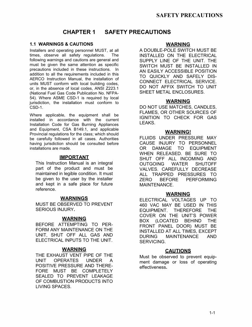
2.4.2 Setting the Unit The unit must be installed on a 4 inch to 6 inch housekeeping pad to ensure proper condensate drainage. If anchoring the unit, refer to the dimensional drawings in Appendix F for anchor locations. A total of 3 lifting tabs are provided at the top of the primary heat exchanger as shown in Figure 2-2. However, USE ONLY TABS 1 AND 2 SHOWN IN FIGURE 2-2 TO MOVE THE ENTIRE UNIT. Tabs 1 and 3 are used only when removing or replacing the unit’s primary heat exchanger. Remove the front top panel from the unit to provide access to the lifting tabs. Remove the four (4) lag screws securing the unit to the shipping skid. Lift the unit off the shipping skid and position it on the 4 inch to 6 inch housekeeping concrete pad (required) in the desired location.
PRIMARY HEATEXCHANGER
LIFTINGTAB 2
LIFTINGTAB 1
BURNERASSEMBLY
LIFTINGTAB 3
Figure 2-2
Lifting Lug Locations
In multiple unit installations, it is important to plan the position of each unit in advance. Sufficient space for piping connections and future service/maintenance requirements must also be taken into consideration. All piping must include ample provisions for expansion.
If installing a Combination Control Panel (CCP) system, it is important to identify the Combination Mode Boilers in advance and place them in the proper physical location. Refer to Chapter 5 for information on Combination Mode Boilers.
INSTALLATION
2-3
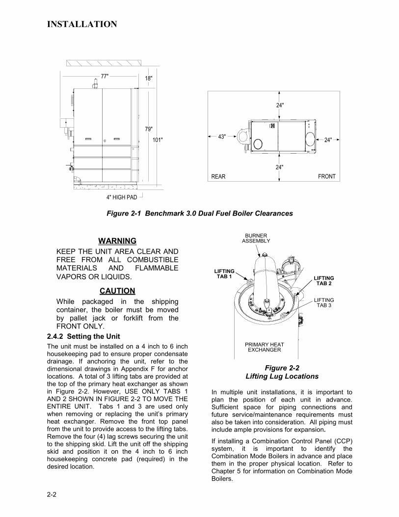
2.4.3 Removal of Support Rod Prior to installation of water supply and return piping, the 24” threaded rod shown in Figure 2-3 must be removed. This rod is installed prior to shipment from the factory to prevent damage to the insulated metal flex hose on the hot water supply outlet of the boiler. In order to install the water supply piping, this rod must be removed as follows:
1. Refer to Figure 2-3 and back off the hex nut on the outlet side of the flex hose.
2. Next, disconnect the coupling nut from the flange stud.
3. Completely remove the threaded rod, hex nut and coupling nut from the boiler.
5/8-11 x 24" LONGTHREADED ROD
5/8-11HEX NUT
5/8-11COUPLING NUT
EXHAUSTMANIFOLD
OUTLETFLANGE
INSULATEDFLEX HOSE
(SEE IMPORTANTNOTE BELOW)
PARTIAL TOP VIEW - REAR Figure 2-3
Location of Threaded Support Rod
IMPORTANT THE INSULATED FLEX HOSE SHOWN IN FIGURE 2-3 MUST BE LEVEL OR SLOPING UPWARD AS IT EXITS THE BOILER. FAILURE TO PROPERLY POSITION THIS HOSE MAY CAUSE INEFFECTIVE AIR ELIMINATION RESULTING IN ELE-VATED TEMPERATURES THAT COULD COMPROMISE THE TOP HEAD GASKET.
2.4.4 Removal of Strap and Packing Material From Heat Exchanger Prior to connecting the external gas supply or electrical power to the unit. the strap and packing material must be removed from the top of the primary heat exchanger. This material is located in the area of the ignitor-injector and staged ignition solenoid on the burner assembly
This can be easily accomplished by removing the top panel nearest to the front of the unit.
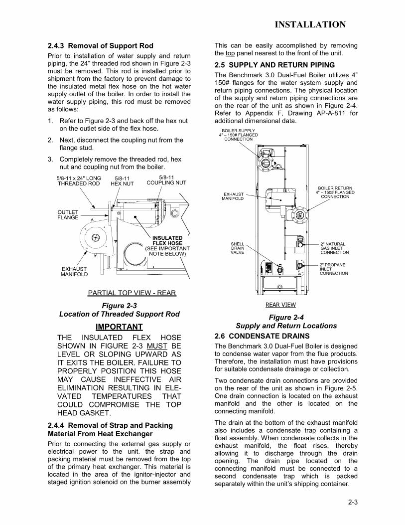
2.5 SUPPLY AND RETURN PIPING The Benchmark 3.0 Dual-Fuel Boiler utilizes 4” 150# flanges for the water system supply and return piping connections. The physical location of the supply and return piping connections are on the rear of the unit as shown in Figure 2-4. Refer to Appendix F, Drawing AP-A-811 for additional dimensional data.
REAR VIEW
BOILER SUPPLY4" – 150# FLANGED
CONNECTION
EXHAUSTMANIFOLD
SHELLDRAINVALVE
BOILER RETURN4" – 150# FLANGED
CONNECTION
2" NATURAL GAS INLET CONNECTION
2" PROPANEINLET CONNECTION
Figure 2-4
Supply and Return Locations 2.6 CONDENSATE DRAINS The Benchmark 3.0 Dual-Fuel Boiler is designed to condense water vapor from the flue products. Therefore, the installation must have provisions for suitable condensate drainage or collection.
Two condensate drain connections are provided on the rear of the unit as shown in Figure 2-5. One drain connection is located on the exhaust manifold and the other is located on the connecting manifold.
The drain at the bottom of the exhaust manifold also includes a condensate trap containing a float assembly. When condensate collects in the exhaust manifold, the float rises, thereby allowing it to discharge through the drain opening. The drain pipe located on the connecting manifold must be connected to a second condensate trap which is packed separately within the unit’s shipping container.

INSTALLATION
2-4
The procedures to install and connect both of the condensate drains are provided in paragraphs 2.6.1 and 2.6.2.
UNITFRAME
CONNECTINGMANIFOLD
DRAINVALVE
CONDENSATEDRAIN PIPE
TOCONDENSATE
TRAP
SHELL
VIEW “B - B”VIEW “A - A”
UNITFRAMEEXHAUST
MANIFOLD
CONDENSATETRAP
DRAIN
HOSE CLAMP
1" I.D.HOSE
TO FLOORDRAIN
EXHAUSTMANIFOLD
CONDENSATETRAP
DRAIN
SHELL DRAINVALVE
CONNECTING MANIFOLD
DRAIN
REAR VIEW
B
B
A
A
Figure 2-5
Condensate Drain Connection Location
2.6.1 Exhaust Manifold Condensate Drain Refer to Figure 2-5, View A – A and install as follows:
1. Connect a length of 1 inch I.D. hose (part no. 91030) to the drain on the connecting manifold and secure it in place with a hose clamp.
2. Route the hose to a nearby floor drain.
2.6.2 Connecting Manifold Condensate Drain The connecting manifold drain pipe shown in Figure 2-5, View B – B must be connected to a separate condensate drain trap external to the unit. This condensate trap (part no. 24060) is supplied with the unit along with a trap adapter and a 3/4” NPT x 5” long nipple. Refer to Figure 2-6 and install the trap as follows:
The condensate trap described in the following steps can be installed on the floor behind the unit as shown in Figure 2-6. Ensure that the condensate trap inlet is level with or below the connecting manifold drain pipe. Ensure that the outlet hose from the trap slopes away (down) from the trap.
1. Apply Teflon tape to the threads of the 3/4” x 5” long nipple provided with the boiler.
2. Attach the 3/4” NPT nipple between the condensate trap inlet and the trap adaptor (Figure 2-6).
3. Attach another 3/4” NPT nipple (not sup-plied) to the condensate trap outlet on the lower part of the trap.
4. Connect the condensate trap and adaptor to the connecting manifold drain pipe. Position the trap so it is level and then tighten the thumb screw on the adaptor.
5. Place a suitable support under the condensate trap to maintain the trap in the level position.
6. Connect a length of 1” I.D. polypropylene hose to the outlet side of the condensate trap and route it to a nearby floor drain.
If desired, a Tee fitting may be used to connect the two drain hoses from the exhaust manifold and the outlet side of the of the condensate trap attached to the connecting manifold.
If a floor drain is not available, a condensate pump can be used to remove the condensate to drain. The maximum condensate flow rate is 20 GPH. The condensate drain trap, associated fittings and drain lines must be removable for routine maintenance.

INSTALLATION
2-5
CONDENSATE TRAP
CONNECTING MANIFOLD
DRAIN PIPE
3/4" NPTNIPPLES
TOFLOORDRAIN
CLAMP
1" I.D.HOSE
ADAPTOR
Figure 2-6 Condensate Trap Installation
2.7 GAS SUPPLY PIPING The AERCO Benchmark 3.0 Gas Components and Supply Design Guide, GF-3030 must be consulted prior to designing or installing any gas supply piping.
WARNING NEVER USE MATCHES, CANDLES, FLAMES OR OTHER SOURCES OF IGNITION TO CHECK FOR GAS LEAKS.
CAUTION Many soaps used for gas pipe leak testing are corrosive to metals. There-fore, piping must be rinsed thoroughly with clean water after leak checks have been completed.
All gas piping must be arranged so that it does not interfere with removal of any covers, inhibit service/maintenance, or restrict access between the unit and walls, or another unit.
Benchmark 3.0 Dual-Fuel units contain two 2 inch gas inlet connections on the rear of the unit as shown in Figure 2-4. If one of the fuel sources is not being piped due to its unavailability, the inlet must be capped.
Prior to installation, all pipes should be de-burred and internally cleared of any scale, metal chips or other foreign particles. Do Not install any flexible connectors or unapproved gas fittings. Piping must be supported from the floor, ceiling or walls only and must not be supported by the unit.
A suitable piping compound, approved for use with natural gas, should be used. Any excess must be wiped off to prevent clogging of components.
To avoid unit damage when pressure testing gas piping, isolate the unit from the gas supply piping. At no time should the gas pressure applied to the unit exceed 2 psi. Leak test all external piping thoroughly using a soap and water solution or suitable equivalent. The gas piping used must meet all applicable codes.
2.7.1 Gas Supply Specifications The gas supply input specifications to the unit for Natural Gas and Propane are as follows:
• Natural Gas - The maximum static pressure to the unit must not exceed 2 psi. The gas supply pressure to the unit must be of sufficient capacity to provide 3000 cfh while maintaining the gas pressure at 5.7" W.C. for FM gas trains, or 6.5" W.C. for IRI gas trains.
• Propane - The maximum static pressure to the unit must not exceed 2 psi. The gas supply pressure to the unit must be of sufficient capacity to provide 1200 cfh while maintaining the gas pressure at 3.5" W.C. for FM or IRI gas trains.
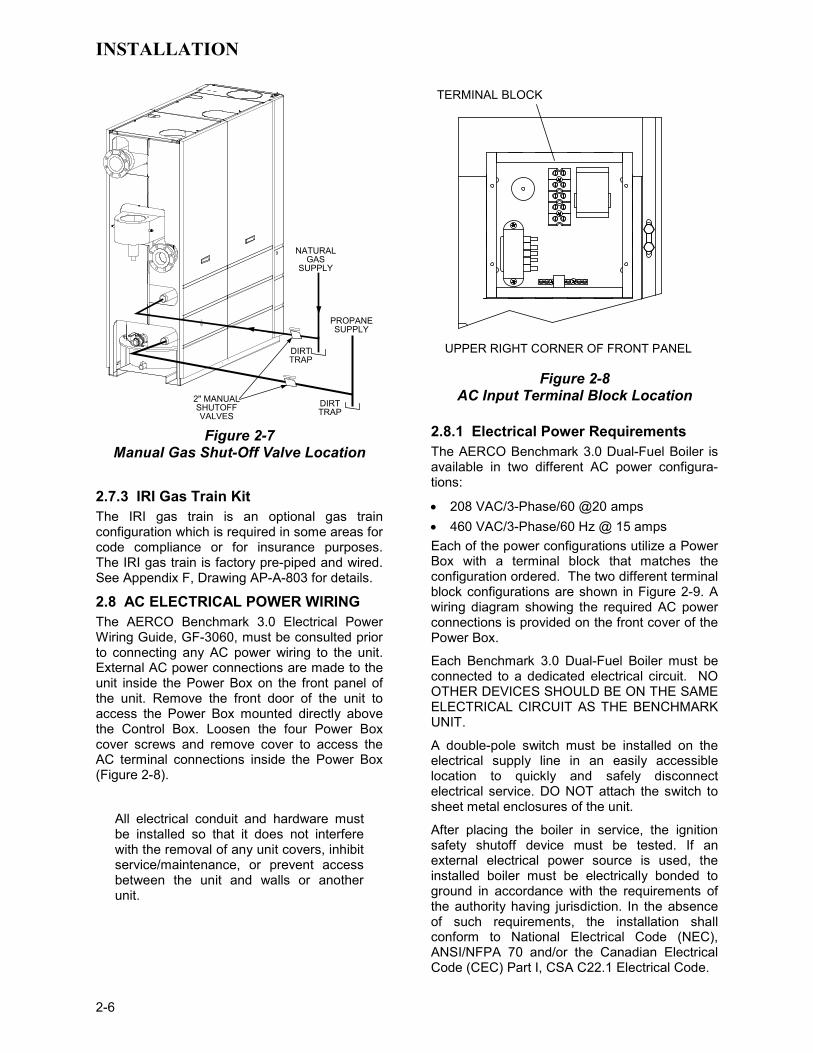
2.7.2 Manual Gas Shutoff Valve Two manual shut-off valves must be installed in the gas supply lines upstream of the Boiler as shown in Figure 2-7. Maximum allowable gas pressure to the Boiler for each line is 2 psi.
INSTALLATION
2-6
NATURALGAS
SUPPLY
DIRTTRAP
2" MANUALSHUTOFFVALVES
PROPANESUPPLY
DIRTTRAP
Figure 2-7
Manual Gas Shut-Off Valve Location
2.7.3 IRI Gas Train Kit The IRI gas train is an optional gas train configuration which is required in some areas for code compliance or for insurance purposes. The IRI gas train is factory pre-piped and wired. See Appendix F, Drawing AP-A-803 for details.
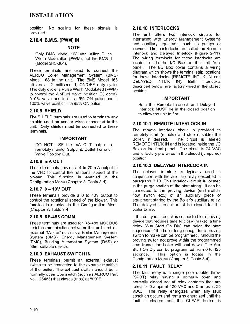
2.8 AC ELECTRICAL POWER WIRING The AERCO Benchmark 3.0 Electrical Power Wiring Guide, GF-3060, must be consulted prior to connecting any AC power wiring to the unit. External AC power connections are made to the unit inside the Power Box on the front panel of the unit. Remove the front door of the unit to access the Power Box mounted directly above the Control Box. Loosen the four Power Box cover screws and remove cover to access the AC terminal connections inside the Power Box (Figure 2-8).
All electrical conduit and hardware must be installed so that it does not interfere with the removal of any unit covers, inhibit service/maintenance, or prevent access between the unit and walls or another unit.
UPPER RIGHT CORNER OF FRONT PANEL
TERMINAL BLOCK
Figure 2-8
AC Input Terminal Block Location 2.8.1 Electrical Power Requirements The AERCO Benchmark 3.0 Dual-Fuel Boiler is available in two different AC power configura-tions:
• 208 VAC/3-Phase/60 @20 amps • 460 VAC/3-Phase/60 Hz @ 15 amps Each of the power configurations utilize a Power Box with a terminal block that matches the configuration ordered. The two different terminal block configurations are shown in Figure 2-9. A wiring diagram showing the required AC power connections is provided on the front cover of the Power Box.
Each Benchmark 3.0 Dual-Fuel Boiler must be connected to a dedicated electrical circuit. NO OTHER DEVICES SHOULD BE ON THE SAME ELECTRICAL CIRCUIT AS THE BENCHMARK UNIT.
A double-pole switch must be installed on the electrical supply line in an easily accessible location to quickly and safely disconnect electrical service. DO NOT attach the switch to sheet metal enclosures of the unit.
After placing the boiler in service, the ignition safety shutoff device must be tested. If an external electrical power source is used, the installed boiler must be electrically bonded to ground in accordance with the requirements of the authority having jurisdiction. In the absence of such requirements, the installation shall conform to National Electrical Code (NEC), ANSI/NFPA 70 and/or the Canadian Electrical Code (CEC) Part I, CSA C22.1 Electrical Code.

INSTALLATION
2-7
For electrical power wiring diagrams, see the AERCO Benchmark 3.0 Electrical Power Wiring Guide, (GF-3060).
GND
NEU
L2
L3
L1
208 VAC, 3 PHASE
208 VAC, 3 Phase
GND
L2
L3
L1
460 VAC, 3 PHASE
460 VAC, 3 Phase
Figure 2-9
AC Terminal Block Configurations
2.9 MODES OF OPERATION AND FIELD CONTROL WIRING The Benchmark 3.0 Dual-Fuel Boiler is available in several different modes of operation. While each unit is factory configured and wired for its intended mode, some additional field wiring may be required to complete the installation. This wiring is typically connected to the Input/Output (I/O) Box located on the lower portion of the unit front panel (Figure 2-10) behind the removable front door.
To access the I/O Box terminal strips shown in Figure 2-10, loosen the four cover screws and remove the cover. All field wiring is installed from the rear of the panel by routing the wires through one of the four bushings provided.
TERMINALSTRIPS
LOWER RIGHT CORNEROF FRONT PANEL
Figure 2-10. Input/Output (I/O) Box Location
Refer to the wiring diagram provided on the cover of the I/O Box (Figure 2-11) when making all wiring connections.
Brief descriptions of each mode of operation, and their wiring requirements, are provided in the following paragraphs. Additional information concerning field wiring is provided in paragraphs 2.9.1 through 2.9.9. Refer to Chapter 5 for detailed information on the available modes of operation.

INSTALLATION
2-8
mA OUT
RS-485 COMM.
+
-
+-
ANALOG IN
SENSOR COMMONOUTDOOR SENSOR IN REMOTE INTL'K IN
B.M.S. (PWM) IN
SHIELD
+-
+-
(AIR) AUX SENSOR IN
NOT USED
EXHAUST SWITCH IN
DELAYED INTL'K IN
FAULT RELAY120 VAC, 5A, RES
AUX RELAY120 VAC, 5A, RES
G
RELAY CONTACTS:120 VAC, 30 VDC5 AMPS RESISTIVE
DANGER120 VAC USED
IN THIS BOX
NOT USED NOT USEDNCCOMNO
NCCOMNO
NOT USED0 – 10VAGND
Figure 2-11. I/O Box Terminal Strip 2.9.1 Constant Setpoint Mode The Constant Setpoint Mode is used when it is desired to have a fixed setpoint that does not deviate. No wiring connections, other than AC electrical power connections, are required for this mode. However, if desired, fault monitoring or enable/disable interlock wiring can be utilized (see paragraphs 2.9.9.1 and 2.9.10).
2.9.2 Indoor/Outdoor Reset Mode This mode of operation increases supply water temperature, as outdoor temperatures decrease. An outside air temperature sensor (AERCO Part No. 122790) is required. The sensor MUST BE wired to the I/O Box wiring terminals (see Figure 2-11). Refer to paragraph 2.10.1 for additional information on outside air temperature sensor installation.
2.9.3 Boiler Management System Mode NOTE
BMS Model 168 can utilize either pulse width modulation (PWM) or RS485 Modbus signaling to the Boiler. BMS II Model 5R5-384 can utilize only RS485 signaling to the Boiler.
When using an AERCO Boiler Management System (BMS), the field wiring is connected between the BMS Panel and each Boiler’s I/O Box terminal strip (Figure 2-11). Twisted shielded pair wire from 18 to 22 AWG must be utilized for the connections. The BMS Mode can utilize either pulse width modulation (PWM)
signaling, or RS485 Modbus signaling. For PWM signaling, connections are made from the AERCO Boiler Management System to the B.M.S. (PWM) IN terminals on the I/O Box terminal strip. For RS485 Modus signaling, connections are made from the BMS to the RS485 COMM terminals on the I/O Box terminal strip. Polarity must be maintained and the shield must be connected only at the AERCO BMS. The boiler end of the shield must be left floating. For additional instructions, refer to Chapter 5, paragraph 5.6 in this manual. Also, refer to GF-108M (BMS Model 168) and GF-124 (BMS II Model 5R5-384), BMS -Operations Guides.
2.9.4 Remote Setpoint and Direct Drive Modes The Benchmark 3.0 Dual-Fuel Boiler can accept several types of signal formats from an Energy Management System (EMS), Building Automation System (BAS) or other source, to control either the setpoint (Remote Setpoint Mode) or air/fuel valve position - % open (Direct Drive Mode) of the Boiler. These formats are: • 4 to 20 mA/1 to 5 VDC • 0 to 20 mA/0 to 5 VDC • PWM – (Pulse Width Modulated signal. See
para. 2.10.4) • Network (RS485 Modbus. See para. 2.10.7) While it is possible to control a boiler or boilers using one of the previously described modes of operation, it may not be the method best suited for the application. Prior to selecting one of these modes of operation, it is recommended that you consult with your local AERCO

INSTALLATION
2-9
representative or the factory for the mode of operation that will work best with your application. For more information on wiring the 4 to 20 mA / 1to 5VDC or the 0 to 20 mA / 0 to 5 VDC, see paragraph 2.9.3.
2.9.5 Combination Mode NOTE
Only BMS Model 168 can be utilized for the Combination Mode, not the BMS II (Model 5R5-384).
With a Combination Mode unit, field wiring is between the unit’s I/O Box wiring terminals, the CCP (Combination Control Panel), and the BMS Model 168 (Boiler Management System). The wiring must be accomplished using twisted-shielded pair wire from 18 to 22 AWG. Polarity must be maintained. For further instructions and wiring diagrams, refer to the GF-108 Boiler Management System Operations Guide and the CCP-1 data sheet.
2.10 I/O BOX CONNECTIONS The types of input and output signals and devices to be connected to the I/O Box terminals shown in Figure 2-11 are described in the following paragraphs.
CAUTION DO NOT make any connections to the I/O Box terminals labeled “NOT USED”. Attempting to do so may cause equipment damage.
2.10.1 OUTDOOR SENSOR IN An outdoor air temperature sensor (AERCO Part No. 122790) will be required primarily for the Indoor/Outdoor reset mode of operation. It can also be used with another mode if it is desired to use the outdoor sensor enable/disable feature. This feature allows the boiler to be enabled or disabled based on the outdoor air temperature.
The factory default for the outdoor sensor is DISABLED. To enable the sensor and/or select an enable/disable outdoor temperature, see the Configuration menu in Chapter 3.
The outdoor sensor may be wired up to 200 feet from the boiler. It is connected to the OUTDOOR SENSOR IN and SENSOR COMMON terminals in the I/O Box (see Figures 2-10 and 2-11). Wire the sensor using a twisted shielded pair wire from 18 to 22 AWG. There is no polarity to observe when terminating these wires. The shield is to be connected only to the terminals labeled SHIELD in the I/O Box. The sensor end of the shield must be left free and ungrounded.
When mounting the sensor, it must be located on the North side of the building where an average outside air temperature is expected. The sensor must be shielded from direct sunlight as well as impingement by the elements. If a shield is used, it must allow for free air circulation.
2.10.2 AIR SENSOR IN The AIR SENSOR IN is connected to the AUX SENSOR IN and SENSOR COMMON terminals on the I/O board. The AIR SENSOR measures the temperature of the air input to the Air/Fuel Valve. This temperature reading is one of the components used to calculate the rotational speed of the blower used in the combustion Calibration process (Chapter 4).
The AUX SENSOR IN terminals can be used to add an additional temperature sensor for monitoring purposes. This input is always enabled and is a view-only input that can be seen in the Operating Menu. The sensor must be wired to the AUX SENSOR IN and SENSOR COMMON terminals and must be similar to AERCO BALCO wire sensor Part No. 12449. A resistance chart for this sensor is provided in Appendix C.
2.10.3 ANALOG IN The ANALOG IN + and – terminals are used when an external signal is used to drive the Air/Fuel Valve % open position (Direct Drive Mode) or change the setpoint (Remote Setpoint Mode) of the Boiler.
Either a 4 to 20 mA /1 to 5 VDC or a 0 to 20 mA / 0 to 5 VDC signal may be used to vary the setpoint or Ar/Fuel Valve position. The factory default setting is for 4 to 20 mA / 1 to 5 VDC, however this may be changed to 0 to 20 mA / 0 to 5 VDC using the Configuration Menu described in Chapter 3. If voltage rather than current is selected as the drive signal, a DIP switch must be set on the PMC Board located inside the Control Box. Refer to C-More Control Panel Operation Manual GF-112 for information on setting DIP switches.
All of the supplied signals must be floating (ungrounded) signals. Connections between the signal source and the Boiler’s I/O Box must be made using twisted shielded pair wire from 18 to 22 AWG, such as Belden 9841 (see Figure 2-11). Polarity must be maintained. The shield must be connected only at the source end and must be left floating (not connected) at the Boiler’s I/O Box.
Regardless of whether voltage or current is used for the drive signal, they are linearly mapped to a 40°F to 240°F setpoint or a 0% to 100% valve
INSTALLATION
2-10
position. No scaling for these signals is provided.
2.10.4 B.M.S. (PWM) IN NOTE
Only BMS Model 168 can utilize Pulse Width Modulation (PWM), not the BMS II (Model 5R5-384).
These terminals are used to connect the AERCO Boiler Management System (BMS) Model 168 to the unit. The BMS Model 168 utilizes a 12 millisecond, ON/OFF duty cycle. This duty cycle is Pulse Width Modulated (PWM) to control the Air/Fuel Valve position (% open). A 0% valve position = a 5% ON pulse and a 100% valve position = a 95% ON pulse.
2.10.5 SHIELD The SHIELD terminals are used to terminate any shields used on sensor wires connected to the unit. Only shields must be connected to these terminals.
IMPORTANT DO NOT USE the mA OUT output to remotely monitor Setpoint, Outlet Temp or Valve Position Out.
2.10.6 mA OUT These terminals provide a 4 to 20 mA output to the VFD to control the rotational speed of the blower. This function is enabled in the Configuration Menu (Chapter 3, Table 3-4).
2.10.7 0 – 10V OUT These terminals provide a 0 to 10V output to control the rotational speed of the blower. This function is enabled in the Configuration Menu (Chapter 3, Table 3-4).
2.10.8 RS-485 COMM These terminals are used for RS-485 MODBUS serial communication between the unit and an external “Master” such as a Boiler Management System (BMS), Energy Management System (EMS), Building Automation System (BAS) or other suitable device.
2.10.9 EXHAUST SWITCH IN These terminals permit an external exhaust switch to be connected to the exhaust manifold of the boiler. The exhaust switch should be a normally open type switch (such as AERCO Part No. 123463) that closes (trips) at 500°F.
2.10.10 INTERLOCKS The unit offers two interlock circuits for interfacing with Energy Management Systems and auxiliary equipment such as pumps or louvers. These interlocks are called the Remote Interlock and Delayed Interlock (Figure 2-11). The wiring terminals for these interlocks are located inside the I/O Box on the unit front panel. The I/O Box cover contains a wiring diagram which shows the terminal strip locations for these interlocks (REMOTE INTL’K IN and DELAYED INTL’K IN). Both interlocks, described below, are factory wired in the closed position.
IMPORTANT Both the Remote Interlock and Delayed Interlock MUST be in the closed position to allow the unit to fire.
2.10.10.1 REMOTE INTERLOCK IN The remote interlock circuit is provided to remotely start (enable) and stop (disable) the Boiler, if desired. The circuit is labeled REMOTE INTL’K IN and is located inside the I/O Box on the front panel. The circuit is 24 VAC and is factory pre-wired in the closed (jumpered) position.
2.10.10.2 DELAYED INTERLOCK IN The delayed interlock is typically used in conjunction with the auxiliary relay described in paragraph 2.10. This interlock circuit is located in the purge section of the start string. It can be connected to the proving device (end switch, flow switch etc.) of an auxiliary piece of equipment started by the Boiler’s auxiliary relay. The delayed interlock must be closed for the boiler to fire.
If the delayed interlock is connected to a proving device that requires time to close (make), a time delay (Aux Start On Dly) that holds the start sequence of the boiler long enough for a proving switch to make can be programmed. Should the proving switch not prove within the programmed time frame, the boiler will shut down. The Aux Start On Dly can be programmed from 0 to 120 seconds. This option is locate in the Configuration Menu (Chapter 3, Table 3-4).
2.10.11 FAULT RELAY The fault relay is a single pole double throw (SPDT) relay having a normally open and normally closed set of relay contacts that are rated for 5 amps at 120 VAC and 5 amps at 30 VDC. The relay energizes when any fault condition occurs and remains energized until the fault is cleared and the CLEAR button is
INSTALLATION
2-11
depressed. The fault relay connections are shown in Figure 2-11.
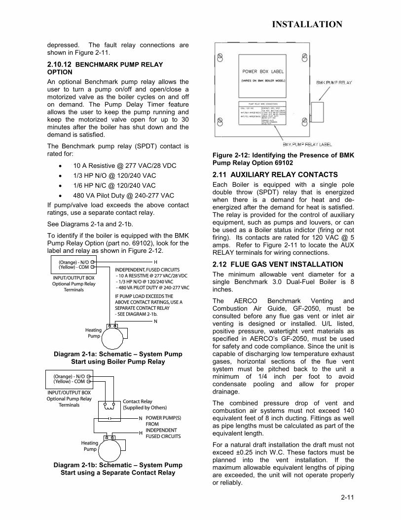
2.10.12 BENCHMARK PUMP RELAY OPTION An optional Benchmark pump relay allows the user to turn a pump on/off and open/close a motorized valve as the boiler cycles on and off on demand. The Pump Delay Timer feature allows the user to keep the pump running and keep the motorized valve open for up to 30 minutes after the boiler has shut down and the demand is satisfied.
The Benchmark pump relay (SPDT) contact is rated for:
• 10 A Resistive @ 277 VAC/28 VDC • 1/3 HP N/O @ 120/240 VAC • 1/6 HP N/C @ 120/240 VAC • 480 VA Pilot Duty @ 240-277 VAC
If pump/valve load exceeds the above contact ratings, use a separate contact relay.
See Diagrams 2-1a and 2-1b.
To identify if the boiler is equipped with the BMK Pump Relay Option (part no. 69102), look for the label and relay as shown in Figure 2-12.
Diagram 2-1a: Schematic – System Pump Start using Boiler Pump Relay
Diagram 2-1b: Schematic – System Pump Start using a Separate Contact Relay
Figure 2-12: Identifying the Presence of BMK Pump Relay Option 69102
2.11 AUXILIARY RELAY CONTACTS Each Boiler is equipped with a single pole double throw (SPDT) relay that is energized when there is a demand for heat and de-energized after the demand for heat is satisfied. The relay is provided for the control of auxiliary equipment, such as pumps and louvers, or can be used as a Boiler status indictor (firing or not firing). Its contacts are rated for 120 VAC @ 5 amps. Refer to Figure 2-11 to locate the AUX RELAY terminals for wiring connections.
2.12 FLUE GAS VENT INSTALLATION The minimum allowable vent diameter for a single Benchmark 3.0 Dual-Fuel Boiler is 8 inches.
The AERCO Benchmark Venting and Combustion Air Guide, GF-2050, must be consulted before any flue gas vent or inlet air venting is designed or installed. U/L listed, positive pressure, watertight vent materials as specified in AERCO’s GF-2050, must be used for safety and code compliance. Since the unit is capable of discharging low temperature exhaust gases, horizontal sections of the flue vent system must be pitched back to the unit a minimum of 1/4 inch per foot to avoid condensate pooling and allow for proper drainage.
The combined pressure drop of vent and combustion air systems must not exceed 140 equivalent feet of 8 inch ducting. Fittings as well as pipe lengths must be calculated as part of the equivalent length.
For a natural draft installation the draft must not exceed ±0.25 inch W.C. These factors must be planned into the vent installation. If the maximum allowable equivalent lengths of piping are exceeded, the unit will not operate properly or reliably.

INSTALLATION
2-12
2.13 COMBUSTION AIR The AERCO Benchmark Venting and Combustion Air Guide, GF-2050 MUST be consulted before any flue or combustion supply air venting is designed or implemented. Combustion air supply is a direct requirement of ANSI 223.1, NFPA-54, CSA B149.1 and local codes. These codes should be consulted before a permanent design is determined.
The combustion air must be free of chlorine, halogenated hydrocarbons, or other chemicals that can become hazardous when used in gas-fired equipment. Common sources of these compounds are swimming pools, degreasing compounds, plastic processing and refrigerants.
Whenever the environment contains these types of chemicals, combustion air must be supplied from a clean area outdoors for the protection and longevity of the equipment.
The AERCO Benchmark 3.0 Dual-Fuel Boiler is UL listed for 100% sealed combustion. It can also be installed using room air, provided there is an adequate supply. (See paragraph 2.13.3 for more information concerning sealed combustion air). If the sealed combustion air option is not being used, an inlet screen will be attached at the air inlet on the top of the unit The more common methods of supplying combustion air are outlined below. For more information concerning combustion air, consult the AERCO Benchmark Venting and Combustion Air Guide, GF-2050.
2.13.1 Combustion Air From Outside the Building Air supplied from outside the building must be provided through two permanent openings. Each opening must have a free area of not less than one square inch for each 4000 BTU/H boiler input. The free area must take into account re-strictions such as louvers and bird screens. For Canada installations, refer to the requirements specified in CSA B149.1.10, 8.4.1 and 8.4.3.
2.13.2 Combustion Air From Inside The Building When combustion air is provided from within the building, it must be supplied through two permanent openings in an interior wall. Each opening must have a free area of not less than one square inch per 1000 BTU/H of total boiler input. The free area must take into account any restrictions such as louvers.
2.13.3 Sealed Combustion The AERCO Benchmark 3.0 Dual-Fuel Boiler is UL listed for 100%-sealed combustion. For sealed combustion installations, the screen on the air inlet duct of the unit must be removed. The inlet air ductwork must then be attached directly to the unit’s air inlet.
In a sealed combustion air application, the combustion air ducting pressure losses must be taken into account when calculating the total maximum allowable venting run. See the AERCO Benchmark Venting and Combustion Air Guide, GF-2050. When using the boiler in a sealed combustion air configuration, each unit must have a minimum 8 inch diameter connection at the unit.
2.13.4 Temporary Combustion Air Filtering During Construction When the AERCO Benchmark 3.0 Dual-Fuel Boiler is used to provide heat temporarily during ongoing building construction, accumulated drywall dust, sawdust and similar particles can accumulate in the unit’s combustion air intake filter and block combustion air flow. In these situations, AERCO recommends that a disposable air intake filter be installed, temporarily, above the boiler combustion air inlet.
AERCO recommends that the temporary air filter be cut from a McMaster-Carr part no. 2122K315 Polyester Air Filter Roll Tackfield, ½” thick, 16” wide, or equivalent. Cover the Benchmark 3.0 air inlet with the blue side of the filter material facing outward to hold the dust on the outside surface. Maximize the surface area of the filter covering the 8" diameter opening by creating a dome out of the filter material.
Cover the flared duct opening with the blue side facing outward. During construction check the filter for dust accumulation and replace it when the accumulation becomes noticeable.

CONTROL PANEL OPERATING PROCEDURES
3-1
CHAPTER 3 CONTROL PANEL OPERATING PROCEDURES
3.1 INTRODUCTION The information in this Chapter provides a guide to the operation of the Benchmark 3.0 Boiler using the Control Panel mounted on the front of the unit. It is imperative that the initial startup of this unit be performed by factory trained personnel. Operation prior to initial startup by factory trained personnel will void the equipment warranty. In addition, the following WARNINGS and CAUTIONS must be observed at all times.
CAUTION All of the installation procedures in Chapter 2 must be completed before attempting to start the unit.
WARNING ELECTRICAL VOLTAGES IN THIS SYSTEM MAY INCLUDE 460, 208 AND 24 VOLTS AC. IT MUST BE SERVICED ONLY BY FACTORY CERTIFIED SERVICE TECHNICIANS
WARNING DO NOT ATTEMPT TO DRY FIRE THE BOILER. STARTING THE UNIT WITHOUT A FULL WATER LEVEL CAN SERIOUSLY DAMAGE THE UNIT AND MAY RESULT IN INJURY TO PERSONNEL OR PROPERTY DAMAGE. THIS SITUATION WILL VOID ANY WARRANTY.
3.2 CONTROL PANEL DESCRIPTION The Benchmark 3.0 Control Panel shown in Figure 3-1 contains all of the controls, indicators and displays necessary to operate, adjust and troubleshoot the Benchmark 3.0 Boiler. These operating controls, indicators and displays are listed and described in Table 3-1. Additional information on these items are provided in the individual operating procedures provided in this Chapter.
1
2
3
4
5
6
7
8
9
10
11
12
Figure 3-1. Control Panel Front View

CONTROL PANEL OPERATING PROCEDURES
3-2
Table 3-1 Operating Controls, Indicators and Displays
ITEM NO.
CONTROL, INDICATOR OR DISPLAY
FUNCTION
1 LED Status Indicators Four Status LEDs indicate the current operating status as follows:
COMM Lights when RS-232 communication is occurring
MANUAL Lights when the unit is being controlled using the front panel keypad.
REMOTE Lights when the unit is being controlled by an external signal from an Energy Management System
DEMAND Lights when there is a demand for heat.
2 OUTLET TEMPERATURE Display
3–Digit, 7–Segment LED display continuously displays the outlet water temperature. The °F or °C LED next to the display lights to indicate whether the displayed temperature is in degrees Fahrenheit or degrees Celsius. The °F or °C blinks when operating in the Deadband Mode.
3 VFD Display Vacuum Fluorescent Display (VFD) consists of 2 lines each capable of displaying up to 16 alphanumeric characters. The information displayed includes: Startup Messages Fault Messages Operating Status Messages Menu Selection
4 RS-232 Port Port permits a Laptop Computer or External Modem to be connected to the unit’s Control Panel.
5 FAULT Indicator Red FAULT LED indicator lights when a boiler alarm condition occurs. An alarm message will appear in the VFD.
6 CLEAR Key Turns off the FAULT indicator and clears the alarm message if the alarm is no longer valid. Lockout type alarms will be latched and cannot be cleared by simply pressing this key. Troubleshooting may be required to clear these types of alarms.
7 READY Indicator Lights ON/OFF switch is set to ON and all Pre-Purge conditions have been satisfied.
8 ON/OFF Switch Enables and disables boiler operation.
9 LOW WATER LEVEL TEST/RESET Switches
Allows operator to test operation of the water level monitor. Pressing TEST opens the water level probe circuit and simulates a Low Water Level alarm. Pressing RESET resets the water level monitor circuit. Pressing the CLEAR key (item 6) resets the display.

CONTROL PANEL OPERATING PROCEDURES
3-3
Table 3-1 Operating Controls, Indicators and Displays – Continued
ITEM NO.
CONTROL, INDICATOR OR DISPLAY
FUNCTION
10 MENU Keypad Consists of 6 keys which provide the following functions for the Control Panel Menus:
MENU Steps through the main menu categories shown in Figure 3-2. The Menu categories wrap around in the order shown.
BACK Allows you to go back to the previous menu level without changing any information. Continuously pressing this key will bring you back to the default status display in the VFD. Also, this key allows you to go back to the top of a main menu category.
▲ (UP) Arrow When in one of the main menu categories (Figure 3-2), pressing the ▲ arrow key will select the displayed menu category. If the CHANGE key was pressed and the menu item is flashing, pressing the ▲ arrow key will increment the selected setting.
▼ (DOWN) Arrow When in one of the main menu categories (Figure 3-2), pressing this key will select the displayed menu category. If the CHANGE key was pressed and the menu item is flashing, pressing the ▼ arrow key will decrement the selected setting.
CHANGE Permits a setting to be changed (edited). When the CHANGE key is pressed, the displayed menu item will begin to flash. Pressing the ▲ or ▼ arrow key when the item is flashing will increment or decrement the displayed setting.
ENTER Saves the modified menu settings in memory. The display
will stop flashing.
11 AUTO/MAN Switch This switch toggles the boiler between the Automatic and Manual modes of operation. When in the Manual (MAN) mode, the front panel controls are enabled and the MANUAL status LED lights. When in the Automatic (AUTO) mode, the MANUAL status LED will be off and the front panel controls disabled.
12 VALVE POSITION Bargraph
20 segment red LED bargraph continuously shows the Air/Fuel Valve open position in 5% increments from 0 to 100%.

CONTROL PANEL OPERATING PROCEDURES
3-4
3.3 CONTROL PANEL MENUS The Control Panel incorporates an extensive menu structure which permits the operator to set up, and configure the unit. The menu structure consists of five major menu categories which are applicable to this manual. These categories are shown in Figure 3-2. Each of the menus shown, contain options which permit operating parameters to be viewed or changed. The menus are protected by a password levels to prevent unauthorized use.
Prior to entering the correct password, the options contained in the Operation, Setup, Configuration and Tuning Menu categories can be viewed. However, with the exception of Internal Setpoint Temperature (Configuration Menu), none of the viewable menu options can be changed.
Once the valid level 1 password (159) is entered, the options listed in the Setup. Configuration and Tuning Menus can be viewed and changed, if desired. The Combustion Cal Menu is protected by the level 2 password which is used in Chapter 4 to perform combustion calibration prior to service use.
3.3.1 Menu Processing Procedure Accessing and initiating each menu and option is accomplished using the Menu Keys shown in Figure 3-1. Therefore, it is imperative that you be thoroughly familiar with the following basic steps before attempting to perform specific menu procedures.
1. The Control Panel will normally be in the Operating Menu and the VFD will display the current unit status. Pressing the ▲ or ▼ arrow key will display the other available data items in the Operating Menu.
2. Press the MENU key. The display will show the Setup Menu, which is the next menu category shown in Figure 3-2. This menu contains the Password option which must be entered if other menu options will be changed.
3. Continue pressing the MENU key until the desired menu is displayed.
4. With the desired menu displayed, press the ▲ or ▼ arrow key. The first option in the selected menu will be displayed.
5. Continue to press the ▲ or ▼ arrow key until the desired menu option is displayed. Pressing the ▲ arrow key will display the available menu options in the Top-Down sequence. Pressing the ▼ arrow key will
display the options in the Bottom-Up sequence. The menu options will wrap-around after the first or last available option is reached.
6. To change the value or setting of a displayed menu option, press the CHANGE key. The displayed option will begin to flash. Press the ▲ or ▼ arrow key to scroll through the available menu option choices for the option to be changed. The menu option choices do not wrap around.
7. To select and store a changed menu item, press the ENTER key.
OPERATING
SETUP
CONFIGURATION
TUNING
COMBUSTION CAL
CALIBRATION(NOT USED IN THIS O & M)
LEVEL 2 PWD
LEVEL 1 PWD
DIAGNOSTICS(NOT USED IN THIS O & M)
Figure 3-2. Menu Structure

CONTROL PANEL OPERATING PROCEDURES
3-5
NOTE The following paragraphs provide brief descriptions of the options contained in each menu. Refer to Appendix A for detailed descriptions of each menu option. Refer to Appendix B for listings and descriptions of displayed startup, status and error messages.
3.4 OPERATING MENU The Operating Menu displays a number of key operating parameters for the unit as listed in Table 3-2. This menu is “Read-Only” and does not allow personnel to change or adjust any displayed items. Since this menu is “Read-Only”, it can be viewed at any time without entering a password. Pressing the ▲ arrow key to display the menu items in the order listed (Top-Down). Pressing the ▼ arrow key will display the menu items in reverse order (Bottom-Up).
3.5 SETUP MENU The Setup Menu (Table 3-3) permits the operator to enter the unit password (159) which is required to change the menu options. To prevent unauthorized use, the password will time-out after 1 hour. Therefore, the correct password must be reentered when required. In addition to permitting password entries, the Setup Menu is also used to enter date and time, units of temperature measurements and entries required for external communication and control of the unit via the RS-232 port. A view-only software version display is also provided to indicate the current Control Box software version.
NOTE The Outdoor Temp display item shown with an asterisk in Table 3-2 will not be displayed unless the Outdoor Sensor function has been enabled in the Configuration Menu (Table 3-4).
Table 3-2. Operating Menu
Available Choices or Limits Menu Item Display Minimum Maximum Default
Status Message
Active Setpoint 40°F 240°F
AIR Temp -70°F 245°F
Outdoor Temp* -70°F 130°F
Valve Position In 0% 100% Valve Position
Flame Strength 0% 100%
Run Cycles 0 999,999,999
Run Hours 0 999,999,999
Fault Log 0 19 0
CONTROL PANEL OPERATING PROCEDURES
3-6
Table 3-3. Setup Menu
Available Choices or Limits Menu Item Display Minimum Maximum Default
Passsword 0 9999 0
Language English English
Time 12:00 am 11:59 pm
Date 01/01/00 12/31/99
Unit of Temp Fahrenheit or Celsius Fahrenheit
Comm Address 0 127 0
Baud Rate 2400, 4800, 9600, 19.2K 9600
Software Ver 0.00 Ver 9.99
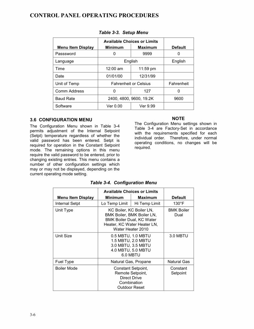
3.6 CONFIGURATION MENU The Configuration Menu shown in Table 3-4 permits adjustment of the Internal Setpoint (Setpt) temperature regardless of whether the valid password has been entered. Setpt is required for operation in the Constant Setpoint mode. The remaining options in this menu require the valid password to be entered, prior to changing existing entries. This menu contains a number of other configuration settings which may or may not be displayed, depending on the current operating mode setting.
NOTE The Configuration Menu settings shown in Table 3-4 are Factory-Set in accordance with the requirements specified for each individual order. Therefore, under normal operating conditions, no changes will be required.
Table 3-4. Configuration Menu
Available Choices or Limits Menu Item Display Minimum Maximum Default
Internal Setpt Lo Temp Limit Hi Temp Limit 130°F Unit Type KC Boiler, KC Boiler LN,
BMK Boiler, BMK Boiler LN, BMK Boiler Dual, KC Water
Heater, KC Water Heater LN, Water Heater 2010
BMK Boiler Dual
Unit Size 0.5 MBTU, 1.0 MBTU 1.5 MBTU, 2.0 MBTU 3.0 MBTU, 3.5 MBTU 4.0 MBTU, 5.0 MBTU
6.0 MBTU
3.0 MBTU
Fuel Type Natural Gas, Propane Natural Gas Boiler Mode Constant Setpoint,
Remote Setpoint, Direct Drive Combination
Outdoor Reset
Constant Setpoint

CONTROL PANEL OPERATING PROCEDURES
3-7
Table 3-4. Configuration Menu - Continued
Available Choices or Limits Menu Item Display Minimum Maximum Default
Remote Signal (If Mode = Remote Setpoint, Direct Drive or Combination)
4 – 20 mA/1 – 5V 0 -20 mA/0 – 5V
PWM Input (BMS) Network
4 – 20 mA, 1-5V
Bldg Ref Temp (If Mode = Outdoor Reset)
40°F 230°F 70°F
Reset Ratio (If Mode = Outdoor Reset)
0.1 9.9 1.2
Outdoor Sensor Enabled or Disabled Disabled System Start Tmp (If Outdoor Sensor = Enabled)
30°F 100°F 60°F
Setpt Lo Limit 40°F Setpt Hi Limit 60°F Setpt Hi Limit Setpt Lo Limit 195°F 195°F Temp Hi Limit 40°F 210°F 195°F Max Valve Position 40% 100% 100% Pump Delay Timer 0 min. 30 min. 0 min. Aux Start On Dly 0 sec. 120 sec. 0 sec.
Failsafe Mode Shutdown or Constant Setpt Shutdown
*Analog Output (See CAUTION at end of Table 3-4 )
Off, Setpoint, Outlet Temp, Valve Position 4-20 mA,
Valve Position 0-10V
*Valve Position 0-10V
Low Fire Timer 2 sec. 600 sec. 2 sec.
Setpt Limiting Enabled or Disabled Disabled
Setpt Limit Band 0°F 10°F 5°F
Network Timeout 5 Sec 999 Sec 30 Sec
HI DB Setpt EN 0% 100% 30%
Demand Offsert 0 25 10
Deadband High 0 25 2
Deadband Low 0 25 2 *CAUTION:
1. DO NOT CHANGE the Analog Output Menu Item from its Default setting (Valve Position 0-10V).
CONTROL PANEL OPERATING PROCEDURES
3-8
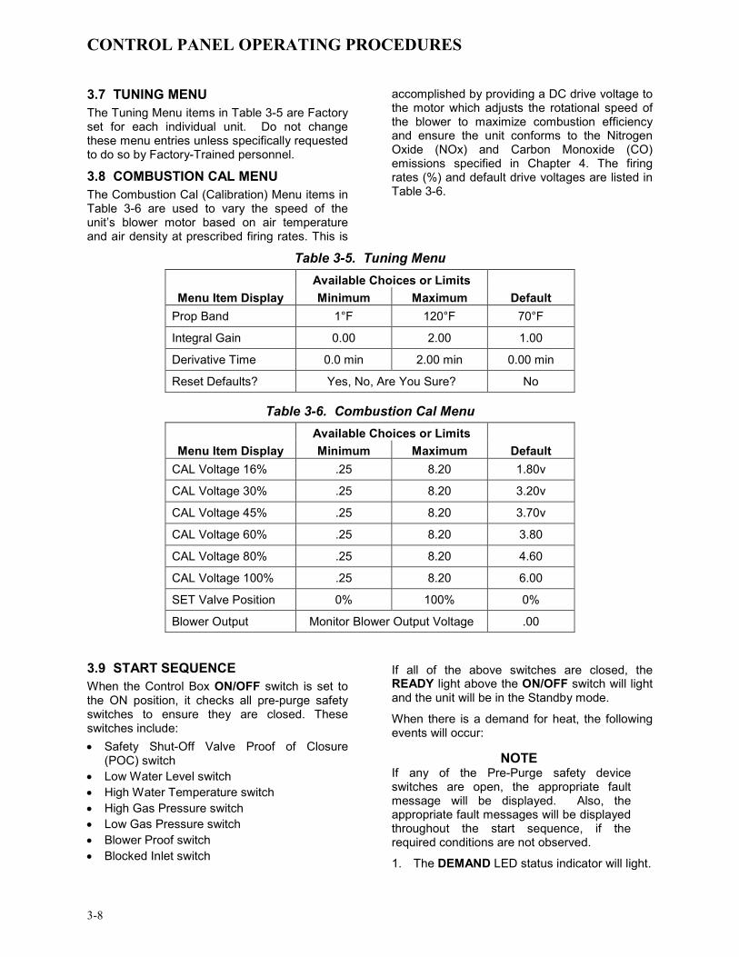
3.7 TUNING MENU The Tuning Menu items in Table 3-5 are Factory set for each individual unit. Do not change these menu entries unless specifically requested to do so by Factory-Trained personnel.
3.8 COMBUSTION CAL MENU The Combustion Cal (Calibration) Menu items in Table 3-6 are used to vary the speed of the unit’s blower motor based on air temperature and air density at prescribed firing rates. This is
accomplished by providing a DC drive voltage to the motor which adjusts the rotational speed of the blower to maximize combustion efficiency and ensure the unit conforms to the Nitrogen Oxide (NOx) and Carbon Monoxide (CO) emissions specified in Chapter 4. The firing rates (%) and default drive voltages are listed in Table 3-6.
Table 3-5. Tuning Menu Available Choices or Limits
Menu Item Display Minimum Maximum Default Prop Band 1°F 120°F 70°F
Integral Gain 0.00 2.00 1.00
Derivative Time 0.0 min 2.00 min 0.00 min
Reset Defaults? Yes, No, Are You Sure? No
Table 3-6. Combustion Cal Menu Available Choices or Limits
Menu Item Display Minimum Maximum Default CAL Voltage 16% .25 8.20 1.80v
CAL Voltage 30% .25 8.20 3.20v
CAL Voltage 45% .25 8.20 3.70v
CAL Voltage 60% .25 8.20 3.80
CAL Voltage 80% .25 8.20 4.60
CAL Voltage 100% .25 8.20 6.00
SET Valve Position 0% 100% 0%
Blower Output Monitor Blower Output Voltage .00 3.9 START SEQUENCE When the Control Box ON/OFF switch is set to the ON position, it checks all pre-purge safety switches to ensure they are closed. These switches include: • Safety Shut-Off Valve Proof of Closure
(POC) switch • Low Water Level switch • High Water Temperature switch • High Gas Pressure switch • Low Gas Pressure switch • Blower Proof switch • Blocked Inlet switch
If all of the above switches are closed, the READY light above the ON/OFF switch will light and the unit will be in the Standby mode.
When there is a demand for heat, the following events will occur:
NOTE If any of the Pre-Purge safety device switches are open, the appropriate fault message will be displayed. Also, the appropriate fault messages will be displayed throughout the start sequence, if the required conditions are not observed.
1. The DEMAND LED status indicator will light.

CONTROL PANEL OPERATING PROCEDURES
3-9
2. The unit checks to ensure that the Proof of Closure (POC) switch in the downstream Safety Shut-Off Valve (SSOV) is closed. See Figure 3-3 for SSOV locations.
PROPANESSOV
NATURALGAS SSOV
PROPANEINLET
NATURALGAS INLET
TOAIR/FUEL
VALVE
Figure 3-3. SSOV Locations
3. With all required safety device switches closed, a purge cycle will be initiated and the following events will occur:
(a) The Blower relay energizes and turns on blower.
(b) The Air/Fuel Valve rotates to the full-open purge position and closes purge position switch. The dial on the Air/Fuel Valve (Figure 3-4) will read 100 to indicate that it is full-open (100%).
(c) The VALVE POSITION bargraph will show 100%.
4. Next, the blower proof switch on the Air/Fuel Valve (Figure 3-5) closes. The display will show Purging and indicate the elapsed time of the purge cycle in seconds.
5. Upon completion of the purge cycle, the Control Box initiates an ignition cycle and the following events occur:
(a) The Air/Fuel Valve rotates to the low-fire ignition position and closes the ignition switch. The dial on the Air/Fuel Valve (Figure 3-6) will read between 25
and 35 to indicate that the valve is in the low-fire position.
(b) The igniter relay is activated and provides ignition spark.
(c) The gas Safety Shut-Off Valve (SSOV) is energized (opened) allowing gas to flow into the Air/Fuel Valve.
100
DETAIL “A”
TO B
LOW
ER
AIR
IN
DIAL(DETAIL “A”)
STEPPERMOTOR
Figure 3-4.
Air/Fuel Valve In Purge Position
BLOWER PROOF SWITCH
AIR/FUELVALVE OUTLETTO BLOWER
Figure 3-5. Blower Proof Switch
CONTROL PANEL OPERATING PROCEDURES
3-10
25
TO B
LOW
ER
AIR
IN
DIAL(DETAIL “A”)
STEPPERMOTOR
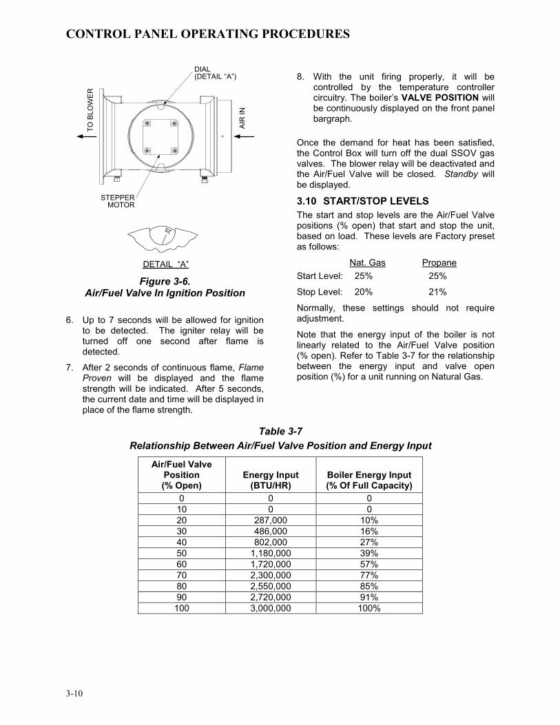
DETAIL “A” Figure 3-6.
Air/Fuel Valve In Ignition Position
6. Up to 7 seconds will be allowed for ignition to be detected. The igniter relay will be turned off one second after flame is detected.
7. After 2 seconds of continuous flame, Flame Proven will be displayed and the flame strength will be indicated. After 5 seconds, the current date and time will be displayed in place of the flame strength.
8. With the unit firing properly, it will be controlled by the temperature controller circuitry. The boiler’s VALVE POSITION will be continuously displayed on the front panel bargraph.
Once the demand for heat has been satisfied, the Control Box will turn off the dual SSOV gas valves. The blower relay will be deactivated and the Air/Fuel Valve will be closed. Standby will be displayed.
3.10 START/STOP LEVELS The start and stop levels are the Air/Fuel Valve positions (% open) that start and stop the unit, based on load. These levels are Factory preset as follows:
Nat. Gas Propane Start Level: 25% 25%
Stop Level: 20% 21%
Normally, these settings should not require adjustment.
Note that the energy input of the boiler is not linearly related to the Air/Fuel Valve position (% open). Refer to Table 3-7 for the relationship between the energy input and valve open position (%) for a unit running on Natural Gas.
Table 3-7
Relationship Between Air/Fuel Valve Position and Energy Input
Air/Fuel Valve Position (% Open)
Energy Input
(BTU/HR)
Boiler Energy Input (% Of Full Capacity)
0 0 0 10 0 0 20 287,000 10% 30 486,000 16% 40 802,000 27% 50 1,180,000 39% 60 1,720,000 57% 70 2,300,000 77% 80 2,550,000 85% 90 2,720,000 91% 100 3,000,000 100%

INITIAL START-UP
4-1
CHAPTER 4 INITIAL START-UP 4.1 INITIAL START-UP REQUIREMENTS The requirements for the initial start-up of the Benchmark 3.0 Dual-Fuel Boiler consist of the following: • Complete installation (Chapter 2) • Set proper controls and limits (Chapter 3) • Perform combustion calibration (Chapter 4) • Set up mode of operation (Chapter 5) • Test safety devices (see Chapter 6)
All applicable Installation procedures in Chapter 2 must be fully completed before performing initial start-up. The initial start-up must be successfully completed prior to putting the unit into service. Starting a unit without the proper piping, venting, or electrical systems can be dangerous and may void the product warranty. The following start-up instructions should be followed precisely in order to operate the unit safely and at a high thermal efficiency, with low flue gas emissions.
Initial unit start-up is to be performed ONLY by AERCO factory trained start-up and service personnel. After performing the start-up procedures in this Chapter, it will be necessary to perform the Mode of Operation settings in Chapter 5, and the Safety Device Testing procedures in Chapter 6 to complete all initial start-up requirements.
AERCO Gas Fired Startup Sheets, included with each Benchmark Boiler, must be completed for each unit for warranty validation. A copy of these sheets must be returned promptly to AERCO at:
AERCO International, Inc. 159 Paris Ave. Northvale, NJ 07647
WARNING DO NOT ATTEMPT TO DRY FIRE THE BOILER. STARTING THE UNIT WITHOUT A FULL WATER LEVEL CAN SERIOUSLY DAMAGE THE UNIT AND MAY RESULT IN INJURY TO PERSONNEL OR PROPERTY DAMAGE. THIS SITUATION WILL VOID ANY WARRANTY.
CAUTION All applicable installation procedures in Chapter 2 must be completed before attempting to start the unit.
4.2 TOOLS AND INSTRUMENTATION FOR COMBUSTION CALIBRATION To properly perform combustion calibration, the proper instruments and tools must be used and correctly attached to the unit. The following paragraphs outline the necessary tools and instrumentation as well as their installation.
4.2.1 Required Tools & Instrumentation The following tools and instrumentation are necessary to perform combustion calibration of the unit:
• Digital Combustion Analyzer: Oxygen accuracy to ± 0.4%; Carbon Monoxide (CO) and Nitrogen Oxide (NOx) resolution to 1PPM.
• 16 inch W.C. manometer or equivalent gauge and plastic tubing.
• 1/8 inch NPT-to-barbed fittings for use with gas supply manometer or gauge.
• Small and large flat blade screwdrivers.
• Tube of silicone adhesive
4.2.2 Installing Gas Supply Manometer The gas supply manometer is installed in the gas train as follows:
1. Close the main manual gas supply shut-off valve upstream of the unit.
2. Remove the front door and left side panels from the boiler to access the gas train components.
3. Remove the 1/8 inch NPT pipe plug from the leak detection ball valve on the downstream side of the Safety Shut Off Valve (SSOV) as shown in Figure 4-1.
4. Install a NPT-to-barbed fitting into the tapped plug port.
5. Attach one end of the plastic tubing to the barbed fitting and the other end to the 16 inch W.C. manometer.

INITIAL START-UP
4-2
1/8" NPT PLUG
(INSTALL MANOMETER HERE)
LEAK DETECTION BALL VALVE
PROPANE HIGH GAS PRESSURE
SWITCH
NATURALGAS SSOV
PROPANESSOV
NATURAL GAS LOW GAS
PRESSURE SWITCH
BALLVALVE
NAT. GAS & PROPANE
PRESSURE REGULATOR FEEDBACK
LINES
NATURAL GAS HIGH GAS PRESSURE
SWITCH
PROPANEINLET
NAT. GASINLET
PROPANE LOW GAS
PRESSURESWITCH
Figure 4-1 1/8 Inch Gas Plug Location
4.2.3 Accessing the Vent Probe Port The unit contains NPT plugs on both the left and right side of the exhaust manifold at the rear of the unit as shown in Figure 4-2. Prepare the port for the combustion analyzer probe as follows:
1. Remove the plug from the probe port on the left or right side of the exhaust manifold.
UNITFRAME
EXHAUSTMANIFOLD
CONDENSATETRAP
DRAIN HOSE
TO FLOORDRAIN
FLUE
VENT PROBE PORT
Figure 4-2 Analyzer Probe Hole Location
2. If necessary, adjust the stop on the combustion analyzer probe so that it will extend mid-way into the flue gas flow. DO NOT install the probe at this time.
IMPORTANT For Dual Fuel units, perform the natural gas combustion calibration procedures in para. 4.3 before performing the propane combustion calibration procedures in para. 4.4. Refer to Appendix K for switchover instructions when changing from Natural Gas to Propane or from Propane to Natural Gas.
4.3 NATURAL GAS COMBUSTION CALIBRATION The Benchmark 3.0 Dual Fuel Boiler is combustion calibrated at the factory prior to shipping. However, recalibration as part of initial start-up is necessary due to changes in the local altitude, gas BTU content, gas supply piping and supply regulators. Factory Test Data sheets are shipped with each unit. These sheets must be filled out and returned to AERCO for proper Warranty Validation.
It is important to perform the following procedure as outlined. This will keep readjustments to a minimum and provide optimum performance.
1. Open the water supply and return valves to the unit and ensure that the system pumps are running.
2. Open the natural gas supply valve(s) to the unit.
3. Set the control panel ON/OFF switch to the OFF position.
4. Turn on external AC power to the unit. The display will show LOSS OF POWER and the time and date.
5. Set the unit to the Manual Mode by pressing the AUTO/MAN key on the control panel. A flashing Manual Valve Position message will be displayed with the present rate in %. Also, the MANUAL LED will light.
6. Adjust the Air/Fuel Valve open position to 0% by pressing the ▼ arrow key.
7. Ensure that the leak detection ball valve (Figure 4-1) downstream of the SSOV is open.
8. Ensure that the Fuel Selector Switch (Figure 4-3 is in the NATURAL GAS position. In addition, ensure that the Fuel Type option in the Configuration Menu (Table 3-4) is set to Natural Gas.

INITIAL START-UP
4-3
9. Set the ON/OFF switch on the unit control panel to the ON position.
POWER BOX
CONTROLPANEL
I/O BOX
TRANSFORMER(460 VAC UNITS ONLY)
VFD
FUELSELECTOR
SWITCH
Figure 4-3
Front View With Door Removed
10. Access the control panel Configuration Menu (Table 3-4) and ensure that the Max Valve Position is set to 100%. (Refer to Chapter 3, para. 3.3 for instructions on changing menu options).
11. Change the valve position to 29% using the ▲ arrow key. The unit should begin its start sequence and fire.
12. Next, increase the valve position to 100%. Verify that the gas pressure downstream of the SSOV is 5” W.C. for both FM and IRI gas trains. If gas pressure adjustment is required, remove the brass hex head cap on the SSOV (Figure 4-4). Make gas regulator adjustments using a short, flat-tip screwdriver to obtain 5” W.C.
NATURALGAS SSOV
PROPANESSOV
BALLVALVE
PROPANEINLET
NAT. GASINLET
BRASS HEX HEAD CAP
(REMOVE TO ADJUST THE
NATURAL GAS REGULATOR)
Figure 4-4
Regulator Adjustment Screw Location
13. With the valve position at 100%, insert the combustion analyzer probe into the flue probe opening and allow enough time for the combustion analyzer to settle.
14. Compare the measured oxygen level to the oxygen range for the inlet air temperature shown in Table 4-1. Also, ensure that the carbon monoxide (CO) and nitrogen oxide (NOx) readings do not exceed the values shown.
Table 4-1
Combustion Oxygen Levels for a 100% Valve Position
Inlet Air Temp
Oxygen % ± 0.2
Carbon Monoxide
NOx
>100°F 4.8 % <100 ppm <30 ppm 90°F 5.0 % <100 ppm <30 ppm 80°F 5.2 % <100 ppm <30 ppm
<70°F 5.3 % <100 ppm <30 ppm

INITIAL START-UP
4-4
15. If necessary, adjust the iris air damper shown in Figure 4-5 until the oxygen level is within the range specified in Table 4-1.
16. Once the oxygen level is within the specified range at 100%, lower the valve position to 85%.
IRIS AIRDAMPER
AIR INLET
BLOWER
AIR/FUELVALVE
A A
USE 1 /2" WRENCH TO
INCREASE (CW) OR DECREASE
(CCW) INLET AIR
IRIS ADJUSTMENT
VIEW A - A
Figure 4-5 Iris Air Damper Location/Adjustment
NOTE The remaining combustion calibration steps are performed using the Combustion Cal Menu included in the C-More Control System. The combustion calibration control functions will be used to adjust the oxygen level (%) at valve positions of 85%, 65%, 45%, 30% and 18% as described in the following steps. These steps assume that the inlet air temperature is within the range of 50°F to 100°F.
17. Press the MENU Key on the front panel of the C-MORE and access the Setup menu. Enter password 6817 and then press the ENTER key.
18. Press the MENU Key on the front panel of the C-MORE until Combustion Cal Menu appears on the C-More display.
19. Press the ▲ arrow key until SET Valve Position appears on the C-MORE display.
20. Press the CHANGE key. SET Valve Position will begin to flash.
21. Press the ▲ arrow key until the SET Valve Position reads 85%. Press the ENTER key.
22. Next, press the down (▼) arrow key until CAL Voltage 85% is displayed.
23. Press the CHANGE key and observe that CAL Voltage 85% is flashing.
24. The oxygen level at the 85% valve position should be as shown below. Also, ensure that the carbon monoxide (CO) and nitrogen oxide (NOx) readings do not exceed the values shown.
Combustion Oxygen Level at
85% Valve Position Oxygen %
± 0.2 Carbon
Monoxide
NOx 6.0 % <100 ppm <30 ppm
25. If the oxygen level is not within the specified range, adjust the level using the ▲ and ▼ arrow keys. This will adjust the output voltage to the blower motor as indicated on the display. Pressing the ▲ arrow key increases the oxygen level and pressing the down ▼ arrow key decreases the oxygen level.
26. Once the oxygen level is within the specified range at 85%, press the ENTER key to store the selected blower output voltage for the 85% valve position.
NOTE
The remaining steps basically repeat the procedures in steps 20 through 27 for valve positions of 65%, 45%, 30% and 18%. However, since oxygen levels vary, these steps are repeated in their entirety. When performing these steps, also ensure that the carbon monoxide (CO) and nitrogen oxide (NOx) readings do not exceed the values shown for each valve position.
INITIAL START-UP
4-5
27. Press the ▲ arrow key until SET Valve Position appears on the C-MORE display.
28. Press the CHANGE key. SET Valve Position will begin to flash.
29. Press the ▼ arrow key until the SET Valve Position reads 65% and press the ENTER key.
30. Press the down ▼ arrow key until CAL Voltage 65% is displayed.
31. Press the CHANGE key. CAL Voltage 65% will begin to flash.
32. The oxygen level at the 65% valve position should be as shown below. Also, ensure that the carbon monoxide (CO) and nitrogen oxide (NOx) readings do not exceed the values shown.
Combustion Oxygen Level at
65% Valve Position Oxygen %
± 0.2 Carbon
Monoxide
NOx 6.3 % <50 ppm <30 ppm
33. If the oxygen level is not within the specified range, adjust the level using the ▲ and ▼ arrow keys. This will adjust the output voltage to the blower motor as indicated on the display. Pressing the ▲ arrow key increases the oxygen level and pressing the ▼ arrow key decreases the oxygen level.
34. Once the oxygen level is within the specified range at 65%, press the ENTER key to store the selected blower output voltage for the 65% valve position.
35. Press the ▲ arrow key until SET Valve Position appears on the C-MORE display.
36. Press the CHANGE key. SET Valve Position will begin to flash.
37. Press the ▼ arrow key until the SET Valve Position reads 45%, then press the ENTER key.
38. Press the ▼ arrow key until CAL Voltage 45% is displayed.
39. Press the CHANGE key. CAL Voltage 45% will begin to flash.
40. The oxygen level at the 45% valve position should be as shown. Also, ensure that the carbon monoxide (CO) and nitrogen oxide (NOx) readings do not exceed the values shown.
Combustion Oxygen Level at 45% Valve Position
Oxygen % ± 0.2
Carbon Monoxide
NOx
6.5 % <50 ppm <30 ppm
41. If the oxygen level is not within the specified range, adjust the level using the ▲ and ▼ arrow keys. This will adjust the output voltage to the blower motor as indicated on the display. Pressing the ▲ arrow key increases the oxygen level and pressing the ▼ arrow key decreases the oxygen level.
42. Once the oxygen level is within the specified range at 45%, press the ENTER key to store the selected blower output voltage for the 45% valve position.
43. Press the ▲ arrow key until SET Valve Position appears on the C-MORE display.
44. Press the CHANGE key. SET Valve Position will begin to flash.
45. Press the ▼ arrow key until the SET Valve Position reads 30%, then press the ENTER key.
46. Press the ▼ arrow key until CAL Voltage 30% is displayed.
47. Press the CHANGE key. CAL Voltage 30% will begin to flash.
48. The oxygen level at the 30% valve position should be as shown below. Also, ensure that the carbon monoxide (CO) and nitrogen oxide (NOx) readings do not exceed the values shown.
Combustion Oxygen Level at
30% Valve Position Oxygen %
± 0.2 Carbon
Monoxide
NOx 6.5 % <50 ppm <30 ppm
49. If the oxygen level is not within the specified range, adjust the level using the ▲ and ▼ arrow keys. This will adjust the output voltage to the blower motor as indicated on the display. Pressing the ▲ arrow key increases the oxygen level and pressing the ▼ arrow key decreases the oxygen level.
50. Once the oxygen level is within the specified range at 30%, press the ENTER key to store the selected blower output voltage for the 30% valve position.

INITIAL START-UP
4-6
51. Press the ▲ arrow key until SET Valve Position appears on the C-MORE display.
52. Press the CHANGE key. SET Valve Position will begin to flash.
53. Press the ▼ arrow key until the SET Valve Position reads 18%, then press the ENTER key.
54. Press the ▼ arrow key until CAL Voltage 18% is displayed.
55. Press the CHANGE key. CAL Voltage 18% will begin to flash.
56. The oxygen level at the 18% valve position should be as shown below. Also, ensure that the carbon monoxide (CO) and nitrogen oxide (NOx) readings do not exceed the values shown.
Combustion Oxygen Level at
18% Valve Position Oxygen %
± 0.2 Carbon
Monoxide
NOx 6.5 % <50 ppm <30 ppm
57. If the oxygen level is not within the specified range, adjust the level using the ▲ and ▼ arrow keys. This will adjust the output voltage to the blower motor as indicated on the display. Pressing the ▲ arrow key increases the oxygen level and pressing the ▼ arrow key decreases the oxygen level.
58. Once the oxygen level is within the specified range at 18%, press the ENTER key to store the selected blower output voltage for the 18% valve position.
IMPORTANT Repeat steps 18 through 58 until the blower output voltage does not require adjustment when sequencing from 85% to 18%.
59. This completes the natural gas combustion calibration procedure.
IMPORTANT Refer to Appendix K for switchover instructions when changing from Natural Gas to Propane or from Propane to Natural Gas.
4.4 PROPANE COMBUSTION CALIBRATION The Benchmark 3.0 Dual Fuel Boiler is combustion calibrated at the factory prior to shipping. Recalibration as part of initial start-up is necessary due to changes in the local altitude, gas BTU content, gas supply piping and supply regulators. Factory Test Data sheets are shipped with each unit. These sheets must be filled out and returned to AERCO for proper Warranty Validation.
It is important to perform the following procedure as outlined. This will keep readjustments to a minimum and provide optimum performance.
1. Open the water supply and return valves to the unit and ensure that the system pumps are running.
2. Open the propane supply valve(s) to the unit.
3. Set the control panel ON/OFF switch to the OFF position.
4. Turn on external AC power to the unit. The display will show LOSS OF POWER and the time and date.
5. Set the unit to the Manual Mode by pressing the AUTO/MAN key. A flashing Manual Valve Position message will be displayed with the present valve position in %. Also, the MANUAL LED will light.
6. Adjust the valve position to 0% by pressing the ▼ arrow key.
7. Ensure that the leak detection ball valve (Figure 4-1) downstream of the propane SSOV is open.
8. Ensure that the Fuel Selector Switch (Figure 4-3 is in the PROPANE position.

INITIAL START-UP
4-7
9. Locate the Fuel Selector Switch on the front of the unit behind the panel door (Figure 4-3).
10. Set the ON/OFF switch on the unit control panel to the ON position.
11. Access the Control Panel Configuration Menu and change the Max Valve Position to 75%. (Refer to Chapter 3, para. 3.3 for instructions on changing menu options).
12. Change the valve position to 29% using the ▲ arrow key. The unit should begin its start sequence and fire.
13. Next, increase the valve position to 75%. Verify that the gas pressure downstream of the propane SSOV is 2.0” W.C. for both FM and IRI gas trains. If gas pressure adjustment is required, remove the brass hex head cap on the propane SSOV (Figure 4-6). Make gas regulator adjustments using a flat-tip screwdriver to obtain 2.0” W.C.
NATURALGAS SSOV
PROPANESSOV BALL
VALVE
PROPANEINLET
NAT. GASINLET
BRASS HEX HEAD CAP
(REMOVE TO ADJUST
PROPANE REGULATOR)
Figure 4-6 Regulator Adjustment Screw Location
14. With the valve position at 75%, insert the combustion analyzer probe into the flue probe opening and allow enough time for the combustion analyzer to settle.
15. Compare the measured oxygen % level to the range shown below. Also, ensure that the carbon monoxide (CO) and nitrogen oxide (NOx) readings do not exceed the values shown.
Combustion Oxygen Level at 75% Valve Position
Oxygen % ± 0.2
Carbon Monoxide
NOx
4.0 % <150 ppm <100 ppm
16. If the oxygen level is not within the specified range, adjust the level using the up (▲) and down (▼) arrow keys on the VFD. Using the up (▲) arrow key will increase oxygen level and the down (▼) arrow key will decrease the oxygen level.
17. Once the oxygen level is within the specified range at 75%, lower the valve position to 60%.
NOTE
The remaining combustion calibration steps are performed using the Combustion Cal Menu included in the C-More Control System. The combustion calibration control functions will be used to adjust the oxygen level (%) at valve positions of 60%, 45%, 30% and 18% as described in the following steps. These steps assume that the inlet air temperature is within the range of 50°F to 100°F.
18. Press the MENU Key on the front panel of the C-MORE and access the Setup menu. Enter password 6817 and then press the ENTER key.
19. Press the MENU Key on the front panel of the C-MORE until Combustion Cal Menu appears on the C-More display.
20. Press the ▲ arrow key until SET Valve Position appears on the C-MORE display.
21. Press the CHANGE key. SET Valve Position will begin to flash.
22. Press the ▲ arrow key until the SET Valve Position reads 60%. Press the ENTER key.
23. Next, press the down (▼) arrow key until CAL Voltage 60% is displayed.
24. Press the CHANGE key and observe that CAL Voltage 60% is flashing.
25. The oxygen level at the 60% valve position should be as shown below. Also, ensure that the carbon monoxide (CO) and nitrogen oxide (NOx) readings do not exceed the values shown.
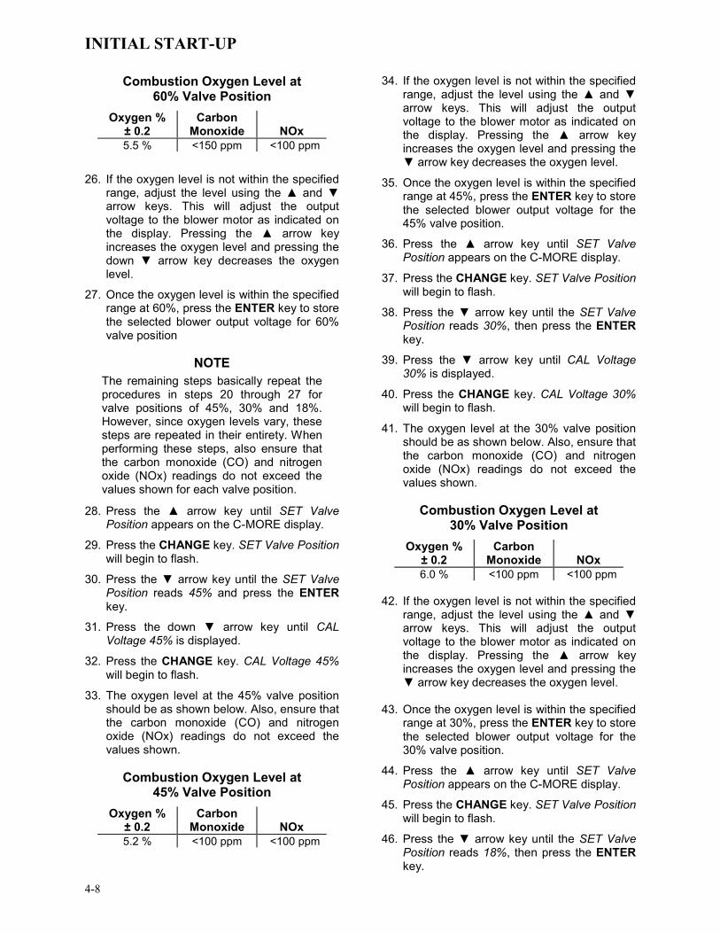
INITIAL START-UP
4-8
Combustion Oxygen Level at 60% Valve Position
Oxygen % ± 0.2
Carbon Monoxide
NOx
5.5 % <150 ppm <100 ppm
26. If the oxygen level is not within the specified range, adjust the level using the ▲ and ▼ arrow keys. This will adjust the output voltage to the blower motor as indicated on the display. Pressing the ▲ arrow key increases the oxygen level and pressing the down ▼ arrow key decreases the oxygen level.
27. Once the oxygen level is within the specified range at 60%, press the ENTER key to store the selected blower output voltage for 60% valve position
NOTE
The remaining steps basically repeat the procedures in steps 20 through 27 for valve positions of 45%, 30% and 18%. However, since oxygen levels vary, these steps are repeated in their entirety. When performing these steps, also ensure that the carbon monoxide (CO) and nitrogen oxide (NOx) readings do not exceed the values shown for each valve position.
28. Press the ▲ arrow key until SET Valve Position appears on the C-MORE display.
29. Press the CHANGE key. SET Valve Position will begin to flash.
30. Press the ▼ arrow key until the SET Valve Position reads 45% and press the ENTER key.
31. Press the down ▼ arrow key until CAL Voltage 45% is displayed.
32. Press the CHANGE key. CAL Voltage 45% will begin to flash.
33. The oxygen level at the 45% valve position should be as shown below. Also, ensure that the carbon monoxide (CO) and nitrogen oxide (NOx) readings do not exceed the values shown.
Combustion Oxygen Level at
45% Valve Position Oxygen %
± 0.2 Carbon
Monoxide
NOx 5.2 % <100 ppm <100 ppm
34. If the oxygen level is not within the specified range, adjust the level using the ▲ and ▼ arrow keys. This will adjust the output voltage to the blower motor as indicated on the display. Pressing the ▲ arrow key increases the oxygen level and pressing the ▼ arrow key decreases the oxygen level.
35. Once the oxygen level is within the specified range at 45%, press the ENTER key to store the selected blower output voltage for the 45% valve position.
36. Press the ▲ arrow key until SET Valve Position appears on the C-MORE display.
37. Press the CHANGE key. SET Valve Position will begin to flash.
38. Press the ▼ arrow key until the SET Valve Position reads 30%, then press the ENTER key.
39. Press the ▼ arrow key until CAL Voltage 30% is displayed.
40. Press the CHANGE key. CAL Voltage 30% will begin to flash.
41. The oxygen level at the 30% valve position should be as shown below. Also, ensure that the carbon monoxide (CO) and nitrogen oxide (NOx) readings do not exceed the values shown.
Combustion Oxygen Level at
30% Valve Position Oxygen %
± 0.2 Carbon
Monoxide
NOx 6.0 % <100 ppm <100 ppm
42. If the oxygen level is not within the specified
range, adjust the level using the ▲ and ▼ arrow keys. This will adjust the output voltage to the blower motor as indicated on the display. Pressing the ▲ arrow key increases the oxygen level and pressing the ▼ arrow key decreases the oxygen level.
43. Once the oxygen level is within the specified
range at 30%, press the ENTER key to store the selected blower output voltage for the 30% valve position.
44. Press the ▲ arrow key until SET Valve Position appears on the C-MORE display.
45. Press the CHANGE key. SET Valve Position will begin to flash.
46. Press the ▼ arrow key until the SET Valve Position reads 18%, then press the ENTER key.

INITIAL START-UP
4-9
47. Press the ▼ arrow key until CAL Voltage 18% is displayed.
48. Press the CHANGE key. CAL Voltage 18% will begin to flash.
49. The oxygen level at the 18% valve position should be as shown below. Also, ensure that the carbon monoxide (CO) and nitrogen oxide (NOx) readings do not exceed the values shown.
Combustion Oxygen Level at
18% Valve Position Oxygen %
± 0.2 Carbon
Monoxide
NOx 5.5 % <100 ppm <100 ppm
50. If the oxygen level is not within the specified range, adjust the level using the ▲ and ▼ arrow keys. This will adjust the output voltage to the blower motor as indicated on the display. Pressing the ▲ arrow key increases the oxygen level and pressing the ▼ arrow key decreases the oxygen level.
51. Once the oxygen level is within the specified range at 18%, press the ENTER key to store the selected blower output voltage for the 16% valve position.
52. This completes the Propane Combustion Calibration procedure.
4.5 UNIT REASSEMBLY Once the combustion calibration adjustments are properly set for Natural Gas and Propane, the unit can be reassembled for service operation.
1. Access the Control Panel Configuration Menu and ensure that the Max Valve Position is set to the desired level for the fuel being used for service operation (100% for Natural Gas; 75% for Propane).
2. Set the control panel ON/OFF switch to the OFF position.
3. Disconnect AC power from the unit.
4. Shut off the gas supply to the unit.
5. Set the Fuel Selector Switch to the corresponding position for the fuel being used for service operation.
6. Remove the manometer and barbed fittings and reinstall the NPT plug using a suitable pipe thread compound.
7. Remove the combustion analyzer probe from the vent hole. Replace the NPT plug in the vent hole using a suitable pipe joint compound.
8. Replace the unit’s side panels and front door.
4.6 OVER-TEMPERATURE LIMIT SWITCHES The unit contains both automatic and manual reset over-temperature limit switches. These switches are mounted on a plate attached to the boiler shell as shown in Figure 4-7. The switches can be accessed by removing the left side panels of the unit. The manual reset switch is not adjustable and is permanently fixed at 200°F. This switch will shut down and lock out the boiler if the water temperature exceeds 200°F. Following an over-temperature condition, it must be manually reset by pressing the RESET button before the boiler can be restarted. The automatic reset over-temperature switch is adjustable and allows the boiler to restart, once the temperature drops below its temperature setting. Set the automatic over-temperature switch to the desired setting.
RESET BUTTON FOR MANUALRESET TEMPERATURE LIMIT
SWITCH
ADJUSTABLETEMPERATURE LIMIT SWITCH
MOUNTING PLATEON SHELL
HIGH LIMIT
Figure 4-7 Over Temperature Limit Switch
Locations

This Page is Intentionally Blank

MODE OF OPERATION
5-1
CHAPTER 5 MODE OF OPERATION
5.1 INTRODUCTION The boiler is capable of being operated in any one of six different modes. The following paragraphs in this Chapter provide descriptions of each of these operating modes. Each boiler is shipped from the factory tested and configured for the ordered mode of operation. All temperature related parameters are at their factory default values which work well in most applications. However, it may be necessary to change certain parameters to customize the unit to the system environment. A complete listing and descriptions of the temperature related parameters are included in Appendix A. Factory defaults are listed in Appendix E. After reading this chapter, parameters can be customized to suit the needs of the specific application.
5.2 INDOOR/OUTDOOR RESET MODE This mode of operation is based on outside air temperatures. As the outside air temperature decreases, the supply header temperature will increase and vice versa. For this mode, it is necessary to install an outside air sensor as well as select a building reference temperature and a reset ratio.
5.2.1 Reset Ratio Reset ratio is an adjustable number from 0.1 to 9.9. Once adjusted, the supply header temperature will increase by that number for each degree that the outside air temperature decreases. For instance, if a reset ratio of 1.6 is used, for each degree that outside air temperature decreases the supply header temperature will increase by 1.6 degrees.
5.2.2 Building Reference Temperature This is a temperature from 40°F to 230°F. Once selected, it is the temperature that the system references to begin increasing its temperature. For instance, if a reset ratio of 1.6 is used, and we select a building reference temperature of 70°F, then at an outside temperature of 69°F, the supply header temperature will increase by 1.6° to 71.6°F.
5.2.3 Outdoor Air Temperature Sensor Installation The outdoor air temperature sensor must be mounted on the North side of the building in an area where the average outside air temperature
is expected. The sensor must be shielded from the sun's direct rays, as well as direct impingement by the elements. If a cover or shield is used, it must allow free air circulation. The sensor may be mounted up to two hundred feet from the unit. Sensor connections are made at the Input/Output (I/O) Box on the front of the boiler. Connections are made at the terminals labeled OUTDOOR SENSOR IN and SENSOR COMMON inside the I/O Box. Use shielded 18 to 22 AWG wire for connections. A wiring diagram is provided on the cover of the I/O Box. Refer to Chapter 2, paragraph 2.9.1 for additional wiring information.
5.2.4 Indoor/ Outdoor Startup Startup in the Indoor/Outdoor Reset Mode is accomplished as follows:
1. Refer to the Indoor/Outdoor reset ratio charts in Appendix D.
2. Choose the chart corresponding to the desired Building Reference Temperature.
3. Go down the left column of the chart to the coldest design outdoor air temperature expected in your area.
NOTE A design engineer typically provides design outdoor air temperature and supply header temperature data
4. Once the design outdoor air temperature is chosen, go across the chart to the desired supply header temperature for the design temperature chosen in step 3.
5. Next, go up that column to the Reset Ratio row to find the corresponding reset ratio.
6. Access the Configuration Menu and scroll through it until the display shows Bldg Ref Temp. (Building Reference Temperature).
7. Press the CHANGE key. The display will begin to flash.
8. Use the ▲ and ▼ arrow keys to select the desired Building Reference Temperature.
9. Press ENTER to save any changes.
10. Next, scroll through the Configuration Menu until the display shows Reset Ratio.

MODE OF OPERATION
5-2
11. Press the CHANGE key. The display will begin to flash.
12. Use the ▲ and ▼ arrow keys to select the Reset Ratio determined in step 5.
13. Press ENTER to save the change. Refer to paragraph 3.3 for detailed instructions on menu changing.
5.3 CONSTANT SETPOINT MODE The Constant Setpoint mode is used when a fixed header temperature is desired. Common uses of this mode of operation include water source heat pump loops, and indirect heat exchangers for potable hot water systems or processes.
No external sensors are required to operate in this mode. While it is necessary to set the desired setpoint temperature, it is not necessary to change any other temperature-related functions. The unit is factory preset with settings that work well in most applications. Prior to changing any temperature-related parameters, other than the setpoint, it is suggested that an AERCO representative be contacted. For descriptions of temperature-related functions and their factory defaults, see Appendices A and E.
5.3.1 Setting the Setpoint The setpoint temperature of the unit is adjustable from 40°F to 240°F. To set the unit for operation in the Constant Setpoint Mode, the following menu settings must be made in the Configuration Menu:
MENU OPTION SETTING
Boiler Mode Constant Setpoint
Internal Setpt Select desired setpoint using ▲ and ▼ arrow keys (40°F to 240°F)
Refer to paragraph 3.3 for detailed instructions on changing menu options.
5.4 REMOTE SETPOINT MODES The unit’s setpoint can be remotely controlled by an Energy Management System (EMS) or Building Automation System (BAS). The Remote Setpoint can be driven by a current or voltage signal within the following ranges:
4-20 mA/1-5 Vdc
0-20 mA/0-5 Vdc
The factory default setting for the Remote Setpoint mode is 4 - 20 mA/1 - 5 Vdc. With this setting, a 4 to 20 mA/1 to 5 Vdc signal, sent by an EMS or BAS, is used to change the unit's setpoint. The 4 mA/1V signal is equal to a 40°F setpoint while a 20 mA /5V signal is equal to a 240°F setpoint. When a 0 to 20 mA/0 to 5 Vdc signal is used, 0 mA is equal to a 40°F setpoint.
In addition to the current and voltage signals described above, the Remote Setpoint mode can also driven by a RS485 Modbus Network signal from an EMS or BAS.
The Remote Setpoint modes of operation can be used to drive single as well as multiple units.
NOTE If a voltage, rather than current signal is used to control the remote setpoint, a DIP switch adjustment must be made on the CPU Board located in the Control Panel Assembly. Contact your local AERCO representative for details.
In order to enable the Remote Setpoint Mode, the following menu setting must be made in the Configuration Menu:
MENU OPTION SETTING
Boiler Mode Remote Setpoint
Remote Signal 4-20mA/1-5V, 0-20mA/0-5V, or Network
Refer to paragraph 3.3 for detailed instructions on changing menu options.
If the Network setting is selected for RS485 Modbus operation, a valid Comm Address must be entered in the Setup Menu. Refer to Modbus Communication Manual GF-114 for additional information.
While it is possible to change the settings of temperature related functions, the unit is factory preset with settings that work well in most applications. It is suggested that an AERCO representative be contacted, prior to changing any temperature related function settings. For descriptions of temperature-related functions and their factory defaults, refer to Appendices A and E.
MODE OF OPERATION
5-3
5.4.1 Remote Setpoint Field Wiring The only wiring connections necessary for the Remote Setpoint mode are connection of the remote signal leads from the source to the unit’s I/O Box. The I/O Box is located on the front panel of the boiler. For either a 4-20mA/0-5V or a 0-20mA/0-5V setting, the connections are made at the ANALOG IN terminals in the I/O Box. For a Network setting, the connections are made at the RS-485 COMM terminals in the I/O Box. The signal must be floating, (ungrounded) at the I/O Box and the wire used must be a two wire shielded pair from 18 to 22 AWG. Polarity must be observed. The source end of the shield must be connected at the source. When driving multiple units, each unit’s wiring must conform to the above.
5.4.2 Remote Setpoint Startup Since this mode of operation is factory preset and the setpoint is being externally controlled, no startup instructions are necessary. In this mode, the REMOTE LED will light when the external signal is present.
To operate the unit in the Manual mode, press the AUTO/MAN switch. The REMOTE LED will go off and the MANUAL LED will light.
To change back to the Remote Setpoint mode, simply press the AUTO/MAN switch. The REMOTE LED will again light and the MANUAL LED will go off.
5.5 DIRECT DRIVE MODES The unit’s air/fuel valve position (% open) can be changed by a remote signal which is typically sent from an Energy Management System (EMS) or from a Building Automation System (BAS). The Direct Drive mode can be driven by a current or voltage signal within the following ranges:
4-20 mA/1-5 Vdc
0-20 mA/0-5 Vdc
The factory default setting for the Direct Drive mode is 4-20 mA/1-5 Vdc. With this setting, a 4 to 20 mA signal, sent by an EMS or BAS is used to change the unit’s valve position from 0% to 100%. A 4 mA/1V signal is equal to a 0% valve position, while a 20 mA /5V signal is equal to a 100% valve position. When a 0-20 mA/0-5 Vdc signal is used, zero is equal to a 0% valve position.
In addition to the current and voltage signals described above, the Direct Drive mode can also
driven by a RS485 Modbus Network signal from an EMS or BAS.
When in a Direct Drive mode, the unit is a slave to the EMS or BAS and does not have a role in temperature control. Direct Drive can be used to drive single, or multiple units.
NOTE If a voltage, rather than current signal is used to control the remote setpoint, a DIP switch adjustment must be made on the CPU Board located in the Control Box Assembly. Contact your local AERCO representative for details.
To enable the Direct Drive Mode, the following menu setting must be made in the Configuration Menu:
MENU OPTION SETTING
Boiler Mode Direct Drive
Remote Signal 4-20mA/1-5V, 0-20mA/0-5V, or Network
Refer to paragraph 3.3 for instructions on changing menu options.
If the Network setting is selected for RS485 Modbus operation, a valid Comm Address must be entered in the Setup Menu. Refer to Modbus Communication Manual GF-114 for additional information.
5.5.1 Direct Drive Field Wiring The only wiring connections necessary for Direct Drive mode are connection of the remote signal leads from the source to the unit’s I/O Box. For either a 4-20mA/0-5V or a 0-20mA/0-5V setting, the connections are made at the ANALOG IN terminals in the I/O Box. For a Network setting, the connections are made at the RS-485 COMM terminals in the I/O Box. The signal must be floating, (ungrounded) at the I/O Box and the wire used must be a two wire shielded pair from 18 to 22 AWG. Polarity must be observed. The source end of the shield must be connected at the source. When driving multiple units, each unit’s wiring must conform to the above.
5.5.2 Direct Drive Startup Since this mode of operation is factory preset and the valve position is being externally controlled, no startup instructions are necessary. In this mode, the REMOTE LED will light when the signal is present.

MODE OF OPERATION
5-4
To operate the unit in manual mode, press the AUTO/MAN switch. The REMOTE LED will go off and the MANUAL LED will light.
To change back to the Direct Drive mode, simply press the AUTO/MAN switch. The REMOTE LED will again light and the MANUAL LED will go off.
5.6 BOILER MANAGEMENT SYSTEM (BMS)
NOTE BMS Model 168 can utilize either pulse width modulation (PWM) or RS485 Modbus signaling to the Boiler. BMS II Model 5R5-384 can utilize only RS485 signaling to the Boiler.
The BMS mode of operation is used in conjunction with an AERCO Boiler Management System. The BMS mode is used when it is desired to operate multiple units in the most efficient manner possible. For this mode of operation, a BMS Header Sensor must be installed between 2 and 10 feet downstream of the LAST boiler in the boiler plant's supply water header. The BMS can control up to 40 boilers; 8 via pulse width modulation (PWM) and up to 32 via Modbus (RS485) network communication. For BMS programming, operation, and Header Sensor installation details, see GF-108M (BMS Model 168) and GF-124 (BMS II Model 5R5-384), BMS Operations Guides. For operation via an RS485 Modbus network, refer to Modbus Communication Manual GF-114.
To enable the BMS Mode, the following menu settings must be made in the Configuration Menu:
MENU OPTION SETTING
Boiler Mode Direct Drive
Remote Signal BMS (PWM Input) or Network (RS485)
Refer to paragraph 3.3 for instructions on changing menu options.
5.6.1 BMS External Field Wiring Wiring connections for BMS control using PWM signaling are made between connector JP2 on the BMS panel (boilers 1 through 8), and the B.M.S. (PWM) IN terminals in the I/O Box on the front of the boilers. Refer to the wiring diagram provided on the cover of the I/O Box.
Wiring connections for RS485 Modbus control are made between connector JP11 on the BMS (boilers 9 through 40) and the RS485 COMM terminals in the I/O Box on the front of the boilers.
Wire the units using shielded twisted pair wire between 18 and 22 AWG. Observe the proper polarity for the B.M.S. (PWM) IN and/or RS485 COMM wiring connections. Shields should be terminated only at the BMS and the boiler end must be left floating. Each unit’s wiring must conform to the above.
5.6.2 BMS Setup and Startup This mode of operation is factory preset and the AERCO BMS controls the firing rate (air/fuel valve % open position). There are no setup instructions for each individual unit.
To operate the unit in manual mode, press the AUTO/MAN switch. The REMOTE LED will go off and the MANUAL LED will light
To change back to the BMS mode, simply press the AUTO/MAN switch. The REMOTE LED will again light and the MANUAL LED will go off.
5.7 COMBINATION CONTROL SYSTEM (CCS)
NOTE Only BMS Model 168 can be utilized for the Combination Mode, not the BMS II (Model 5R5-384).
A Combination Control System (CCS) is one that uses multiple boilers to cover both space-heating and domestic hot water needs. An AERCO Boiler Management System (BMS) Model 168 and a Combination Control Panel (CCP) are necessary to configure this system. Typically, an adequate number of boilers are installed to cover the space-heating load on the design day, however one or more units are used for the domestic hot water load.
The theory behind this type of system is that the maximum space-heating load and the maximum domestic hot water load do not occur simul-taneously.+ Therefore, boilers used for the domestic hot water are capable of switching between constant setpoint and BMS modes of operation. These boilers are the combination units and are referred to as the combo boilers. The combo boilers heat water to a constant setpoint temperature. That water is then circulated through a heat exchanger in a domestic hot water storage tank.

MODE OF OPERATION
5-5
When the space-heating load is such that all the space-heating boilers are at the 100% valve position, the BMS will then ask the Combination Control Panel for the domestic boilers to become space-heating boilers. Provided the domestic hot water load is satisfied, the combo (hot water) boilers will then become space-heating boilers. If the domestic hot water load is not satisfied, the combo boiler(s) remain on the domestic hot water load. If the combo boilers switch over to space heating, but there is a call for domestic hot water, the CCP switches the combo units back to the domestic load.
When the combo units are satisfying the domestic load they are in constant setpoint mode of operation. When the combo units switch over to space heating, their mode of operation changes to the BMS mode. For more information concerning the operation of the Combination Control Panel see the AERCO CCP-1 literature.
5.7.1 Combination Control System Field Wiring Wiring for this system is between the BMS Model 168 panel, the CCP and the B.M.S. (PWM) IN terminals in the I/O Box. Wire the units using a shielded twisted pair of 18 to 22 AWG wire. When wiring multiple units, each unit’s wiring must conform to the above. For a complete CCP system-wiring diagram see the AERCO CCP-1 literature.
5.7.2 Combination Control System Setup and Startup
Setup for the Combination Mode requires entries to be made in the Configuration Menu for boiler mode, remote signal type and setpoint. The setpoint is adjustable from 40°F to 240°F.
Enter the following settings in the Configuration Menu:
MENU OPTION SETTING
Boiler Mode Combination
Remote Signal BMS (PWM Input)
Internal Setpt 40°F to 240°F
Refer to paragraph 3.3 for instructions on changing menu options.
While it is possible to change other temperature-related functions for combination mode, thes functions are preset to their factory default values. These default settings work well in most applications. It is suggested that AERCO be contacted prior to changing settings other than the unit’s setpoint. For a complete listing of temperature related function defaults, see Appendix E.
To set the unit to the manual mode, press the AUTO/MAN switch. The MANUAL LED will light.
To set the unit back to the auto mode, press the AUTO/MAN switch. The MANUAL LED will go off and the REMOTE LED will light.
When the boiler is switched to BMS mode, the AERCO BMS controls the valve position. There are no setup requirements to the boiler(s) in this mode.

This Page Is Intentionally Blank

SAFETY DEVICE TESTING
6-1
CHAPTER 6 SAFETY DEVICE TESTING
6.1 TESTING OF SAFETY DEVICES Periodic safety device testing is required to ensure that the control system and safety devices are operating properly. The Benchmark 3.0 Dual-Fuel control system comprehensively monitors all combustion-related safety devices before, during and after the start sequence. The following tests check to ensure that the system is operating as designed.
Operating controls and safety devices should be tested on a regular basis or following service or replacement. All testing must conform to local codes such as ASME CSD-1.
NOTE MANUAL and AUTO modes of operation are required to perform the following tests. For a complete explanation of these modes, see Chapter 3.
NOTE It will be necessary to remove the front door and side panels from the unit to perform the following tests.
WARNING ELECTRICAL VOLTAGES IN THIS SYSTEM MAY INCLUDE 460, 220, 120 AND 24 VOLTS AC. POWER MUST BE REMOVED PRIOR TO PERFORMING WIRE REMOVAL OR OTHER TEST PROCEDURES THAT CAN RESULT IN ELECTRICAL SHOCK.
6.2 NATURAL GAS LOW GAS PRESSURE SWITCH TEST Refer to Figure 6-1 and ensure that the leak detection ball valve located at the top of the gas train by the high gas pressure switches is closed.
1. Ensure that the Fuel Selector Switch (Figure 4-3) is set to the NATURAL GAS position.
2. Remove the 1/8 “ plug from the ball valve at the natural gas low gas pressure switch shown in the lower-left portion of Figure 6-1.
3. Install a 0 – 16 “ W.C. manometer or a W.C. gauge where the 1/8" plug was removed.
4. Slowly open the ball valve near the low gas pressure switch.
5. Place the unit in Manual Mode and adjust the valve position between 25 and 30%.
6. While the unit is firing, slowly close the external manual gas shut-off valve.
7. The unit should shut down and display a LOW GAS PRESSURE fault message at approximately 2.6” W.C. The FAULT indi-cator should also start flashing.
1/8" NPT PLUG
(INSTALL MANOMETER HERE FOR HIGH GAS PRESSURE TEST)
LEAK DETECTION BALL VALVE
PROPANE HIGH GAS PRESSURE
SWITCH
NATURALGAS SSOV
PROPANESSOV
NATURAL GAS LOW GAS
PRESSURE SWITCH
BALLVALVE
STAGED IGNITION 1/4" BALL VALVE
NAT. GAS & PROPANE
PRESSURE REGULATOR FEEDBACK
LINES
NATURAL GAS HIGH GAS PRESSURE
SWITCH
PROPANEINLET
NAT. GASINLET
PROPANE LOW GAS
PRESSURESWITCH
1/8" NPT PLUG (INSTALL MANOMETER
HERE FOR GAS PRESSURE TEST)
Figure 6-1
Low & High Gas Pressure Testing
8. Fully open the external manual gas shut-off valve and press the CLEAR button on the Control Box.
9. The fault message should clear and the FAULT indicator should go off. The unit should restart.
10. Upon test completion, close the ball valve and remove the manometer. Replace the 1/8 “ plug removed in step 2.

SAFETY DEVICE TESTING
6-2
6.3 PROPANE LOW GAS PRESSURE SWITCH TEST Refer to Figure 6-1 and ensure that the leak detection ball valve located at the top of the gas train by the high gas pressure switches is closed.
1. Ensure that the Fuel Selector Switch (Figure 4-3) is set to the PROPANE position.
2. Remove the 1/8“ plug from the ball valve at the propane low gas pressure switch shown in the lower-right portion of Figure 6-1.
3. Install a 0 – 16 “ W.C. manometer or a W.C. gauge where the 1/8" plug was removed.
4. Slowly open the ball valve near the low gas pressure switch.
5. Place the unit in Manual Mode and adjust the valve position between 25 and 30%.
6. While the unit is firing, slowly close the external manual gas shut-off valve.
7. The unit should shut down and display a LOW GAS PRESSURE fault message at approximately 2.6” W.C. The FAULT indi-cator should also start flashing.
8. Fully open the external manual gas shut-off valve and press the CLEAR button on the Control Box.
9. The fault message should clear and the FAULT indicator should go off. The unit should restart.
10. Upon test completion, close the ball valve and remove the manometer. Replace the 1/8 “ plug removed in step 2.
6.4 NATURAL GAS HIGH GAS PRESSURE SWITCH TEST To simulate a natural gas high gas pressure fault, refer to Figure 6-1 and proceed as follows:
1. Ensure that the Fuel Selector Switch (Figure 4-3) is set to the NATURAL GAS position.
2. Remove the 1/8“ plug from the leak detection ball valve shown in the upper portion of Figure 6-1.
3. Install a 0 – 16” W.C. manometer (or W.C. gauge) where the 1/8” plug was removed.
4. Slowly open the leak detection ball valve.
5. Start the unit in Manual mode at a valve position between 25 and 30%.
6. Slowly increase the gas pressure using the adjustment screw on the natural gas SSOV.
7. The unit should shut down and display a HIGH GAS PRESSURE fault message when the gas pressure exceeds 7” W.C. The FAULT indicator should also start flashing.
8. Reduce the gas pressure back to 5” W.C.
9. Press the CLEAR button on the Control Box to clear the fault.
10. The fault message should clear and the FAULT indicator should go off. The unit should restart.
11. Upon test completion, close the ball valve and remove the manometer. Replace the 1/8“plug removed in step 2.
6.5 PROPANE HIGH GAS PRESSURE SWITCH TEST To simulate a propane high gas pressure fault, refer to Figure 6-1 and proceed as follows:
1. Ensure that the Fuel Selector Switch (Figure 4-3) is set to the PROPANE position.
2. Remove the 1/8“ plug from the leak detection ball valve shown in the upper portion of Figure 6-1.
3. Install a 0 – 16” W.C. manometer (or W.C. gauge) where the 1/8” plug was removed.
4. Slowly open the leak detection ball valve.
5. Start the unit in Manual mode at a valve position between 25 and 30%.
6. Slowly increase the gas pressure using the adjustment screw on the propane SSOV.
7. The unit should shut down and display a HIGH GAS PRESSURE fault message when the gas pressure exceeds 3.5” W.C. The FAULT indicator should also start flashing.
8. Reduce the gas pressure back to 2.1” W.C.
9. Press the CLEAR button on the Control Box to clear the fault.
10. The fault message should clear and the FAULT indicator should go off. The unit should restart.
11. Upon test completion, close the ball valve and remove the manometer. Replace the 1/8“ plug removed in step 2.

SAFETY DEVICE TESTING
6-3
6.6 LOW WATER LEVEL FAULT TEST To simulate a low water level fault:
1. Set the ON/OFF switch to the OFF position
2. Close the water shut-off valves in the supply and return piping to the unit.
3. Slowly open the drain valve on the rear of the unit. If necessary the unit’s relief valve may be opened to aid in draining.
4. Continue draining the unit until a LOW WATER LEVEL fault message is displayed and the FAULT indicator flashes.
5. Place the unit in the Manual Mode and raise the valve position above 30%.
6. Set the ON/OFF switch to the ON position. The READY light should remain off and the unit should not start. If the unit does start, shut the unit off immediately and refer fault to qualified service personnel.
7. Close the drain and pressure relief valve used in draining the unit.
8. Open the water shut-off valve in the return piping to the unit.
9. Open the water supply shut-off valve to the unit to refill.
10. After the shell is full, press the LOW WATER LEVEL RESET button to reset the low water cutoff.
11. Press the CLEAR button to reset the FAULT LED and clear the displayed error message.
12. Set the ON/OFF switch to the ON position. The unit is now ready for operation.
6.7 WATER TEMPERATURE FAULT TEST A high water temperature fault is simulated by adjusting the automatic over-temperature switch. This switch is accessible from the left side of the unit as shown in Figure 6-2.
1. Start the unit in the normal operating mode. Allow the unit to stabilize at its setpoint.
2. Lower the adjustable over-temperature switch setting to match the displayed OUTLET TEMPERATURE.
3. Once the adjustable over-temperature switch setting is approximately at, or just below, the actual outlet water temperature, the unit should shut down. The FAULT
indicator should start flashing and a HIGH WATER TEMP SWITCH OPEN fault message should be displayed. It should not be possible to restart the unit.
4. Reset the adjustable over-temperature switch to its original setting.
5. The unit should start once the adjustable temperature limit switch setting is above the actual outlet water temperature.
6. Once the adjustable over-temperature switch setting is approximately at, or just below, the actual outlet water temperature, the unit should shut down. The FAULT indicator should start flashing and a HIGH WATER TEMP SWITCH OPEN fault message should be displayed. It should not be possible to restart the unit.
7. Reset the adjustable over-temperature switch to its original setting.
8. The unit should start once the adjustable temperature limit switch setting is above the actual outlet water temperature.
RESET BUTTON FOR MANUALRESET TEMPERATURE LIMIT
SWITCH
ADJUSTABLETEMPERATURE LIMIT SWITCH
MOUNTING PLATEON SHELL
HIGH LIMIT
Figure 6-2
Temperature Limit Switch Setting
SAFETY DEVICE TESTING
6-4
6.8 INTERLOCK TESTS The unit is equipped with two interlock circuits called the Remote Interlock and Delayed Interlock. Terminal connections for these circuits are located in the I/O Box (Figure 2-9) and are labeled REMOTE INTL’K IN and DELAYED INTL’K IN. These circuits can shut down the unit in the event that an interlock is opened. These interlocks are shipped from the factory jumpered (closed). However, each of these interlocks may be utilized in the field as a remote stop and start, an emergency cut-off, or to prove that a device such as a pump, gas booster, or louver is operational.
6.8.1 REMOTE INTERLOCK 1. Remove the cover from the I/O Box and
locate the REMOTE INTL’K IN terminals.
2. Start the unit in the Manual Mode and set the valve position between 25% and 30%.
3. If there is a jumper across the REMOTE INTL’K IN terminals, remove one side of the jumper. If the interlock is being controlled by an external device, either open the interlock via the external device or disconnect one of the wires leading to the external device.
4. The unit should shut down and display INTERLOCK OPEN.
5. Once the interlock connection is reconnected, the INTERLOCK OPEN message should automatically clear and the unit should restart.
6.8.2 DELAYED INTERLOCK 1. Remove the cover from the I/O Box and
locate the DELAYED INTL’K IN terminals.
2. Start the unit in the Manual Mode at a valve position between 25% and 30%.
3. If there is a jumper across the DELAYED INTL’K IN terminals, remove one side of the jumper. If the interlock is connected to a proving switch of an external device, disconnect one of the wires leading to the proving switch.
4. The unit should shut down and display a DELAYED INTERLOCK OPEN fault message. The FAULT LED should be flashing.
5. Reconnect the wire or jumper removed in step 3 to restore the interlock.
6. Press the CLEAR button to reset the fault
7. The unit should start.
6.9 FLAME FAULT TESTS Flame faults can occur during ignition or while the unit is already running. To simulate each of these fault conditions, proceed as follows:
1. Set the ON/OFF switch to the OFF position.
2. Place the unit in the Manual Mode and set the valve position between 25% and 30%.
3. Close the manual gas shutoff valve located between the Safety Shut-Off Valve (SSOV) and the Air/Fuel Valve (see Figure 6-3).
4. Set the ON/OFF switch to the ON position to start the unit.
5. The unit should shut down after reaching the Ignition cycle and display FLAME LOSS DURING IGN.
6. Open the valve previously closed in step 3 and press the CLEAR button.
7. Restart the unit and allow it to prove flame.
8. Once flame is proven, close the manual gas valve located between the SSOV and the Air/Fuel Valve.
9. The unit should shut down and display FLAME LOSS DURING RUN.
10. Open the valve previously closed in step 8.
11. Press the CLEAR button. The unit should restart and fire.

SAFETY DEVICE TESTING
6-5
PARTIAL LEFT SIDE VIEW
BLOWER
AIRINLET
BLOCKED AIR INLETSWITCH
AIR/FUELVALVE
MANUAL GASSHUTOFF VALVE
HANDLE
PROPANE
PA
RT
OF
FRA
ME
GA
S IN
LETS
NATURAL GAS
SS
OV
s (2
)
Figure 6-3 Manual Gas Shut-Off Valve Location
6.10 AIR FLOW FAULT TESTS These tests check the operation of the Blower Proof Switch and Blocked Inlet Switch shown in Figure 6-3.
1. Disable the blower output drive voltage as follows:
(a) Press the MENU key until CONFIGUR-ATION MENU is displayed.
(b) Press the ▲ arrow key until the ANA-LOG OUTPUT function is displayed, then press the CHANGE key.
(c) Press the ▼ arrow key until OFF is displayed, then press the ENTER key.
2. Start the unit in the Manual Mode at a valve position between 25% and 30%.
3. The unit should shut down and execute an IGNITION RETRY cycle by performing the following steps:
(a) The unit will execute a 30 second re-ignition delay and display WAIT RETRY PAUSE.
(b) The unit will then execute a standard ignition sequence and display WAIT IGNITION RETRY.
4. The unit should perform two IGNITION RETRY cycles and then shut down on the third successive ignition attempt. The unit will display AIRFLOW FAULT DURING PURGE.
5. Re-enable the blower output drive voltage by performing the following steps:
(a) Press the MENU key until CONFIGUR-ATION MENU is displayed.
(b) Press the ▲ arrow key until the ANA-LOG OUTPUT function is displayed, then press the CHANGE key.
(c) Press the ▲ arrow key until VALVE POSITION 0-10V is displayed, then press the ENTER key.
6. Once the unit has proved flame, turn off the blower by going to the Configuration Menu, Analog Output menu item and select OFF.
7. The Blower Proof Switch will open and the blower should stop. The unit should shut down and display AIRFLOW FAULT DURING RUN.
8. Go to the Configuration Menu, Analog Output item and select Fire Rate 0-10v.
9. Press the CLEAR button. The unit should restart.
10. Next, check the Blocked Inlet Switch by first noting the current position of the Iris Air Damper and then closing the Damper to position 8.
11. .The unit should shut down and again display AIRFLOW FAULT DURING RUN.
12. Return the Iris Air Damper to its previous setting.
13. Press the CLEAR button. The unit should restart.
6.11 SSOV PROOF OF CLOSURE SWITCH This test can be performed when the unit is set up to run on either natural gas or proane fuel. Downstream SSOVs #1 (natural gas) and #3 (propane) shown in Figure 6-1 contain the proof

SAFETY DEVICE TESTING
6-6
of closure switches. The proof of closure switch circuit is checked as follows:
1. Set the unit’s ON/OFF switch to the OFF position.
2. Place the unit in Manual Mode and set the valve position between 25% and 30%
3. Refer to Figure 6-1 and locate downstream SSOV #1(natural gas).
4. Remove the cover from SSOV #1 by loosening the screw shown in Figure 6-4. Lift off the cover to access the terminal wiring connections.
5. Disconnect wire #148 from SSOV #1 to “open” the proof of closure switch circuit. When wire #148 is disconnected, it opens the proof of closure switch circuit for both the natural gas and propane downstream SSOVs.
6. The unit should fault and display SSOV SWITCH OPEN.
7. Replace wire #148 and press the CLEAR button.
8. Set the ON/OFF switch to ON to start the unit.
9. Remove the wire again when the unit reaches the purge cycle and PURGING is displayed.
10. The unit should shut down and display SSOV FAULT DURING PURGE.
11. Replace the wire on SSOV #1 and press the CLEAR button. The unit should restart.
ACTUATORCOVER SCREW
SSOV #1ACTUATOR
COVER
Figure 6-4 SSOV #1 Actuator Cover Location
6.12 PURGE SWITCH OPEN DURING PURGE The Purge Switch (and Ignition Switch) is located on the Air/Fuel Valve. To check the switch, proceed as follows:
1. Set the unit’s ON/OFF switch to the OFF position. Place the unit in manual mode and set the fire rate between 25% and 30%.
2. Remove the Air/Fuel Valve cover by rotating the cover counterclockwise to unlock it and then lift up (see Figure 6-5).
3. Remove one of the two wires (#171 or #172) from the Purge Switch (Figure 6-6).
4. Initiate a unit start sequence.
5. The unit should begin it’s start sequence, then shut down and display PRG SWITCH OPEN DURING PURGE.
6. Replace the wire on the Purge Switch and depress the CLEAR button. The unit should restart.
6.13 IGNITION SWITCH OPEN DURING IGNITION The Ignition Switch (and the Purge Switch) is located on the Air/Fuel Valve. To check the switch, proceed as follows:
1. Set the unit’s ON/OFF switch to the OFF position.
2. Place the unit in Manual Mode and set the valve position between 25% and 30%.
3. Remove the Air/Fuel Valve cover (Figure 6-5) by rotating the cover counterclockwise to unlock and lift up to remove.
4. Remove one of the two wires (#169 or #170) from the Ignition Switch (Figure 6-6).
5. Initiate a unit start sequence.
6. The unit should begin it’s start sequence and then shut down and display IGN SWITCH OPEN DURING IGNITION.
7. Replace the wire on the Ignition Switch and press the CLEAR button. The unit should restart.

SAFETY DEVICE TESTING
6-7
AIR/FUEL VALVE COVER(ROTATE CCW TO REMOVE)
Figure 6-5 Air/Fuel Valve Cover Location
STEPPER MOTOR DIAL
172171
169
170
IGNITIONPOSITIONSWITCH
PURGEPOSITIONSWITCH
AIRIN
TOBLOWER
Figure 6-6 Air/Fuel Valve Purge and Ignition Switch
Locations
6.14 SAFETY PRESSURE RELIEF VALVE TEST Test the safety Pressure Relief Valve in accordance with ASME Boiler and Pressure Vessel Code, Section VI.

This Page Is Intentionally Blank

MAINTENANCE
7-1
CHAPTER 7 MAINTENANCE
7.1 MAINTENANCE SCHEDULE The unit requires regular routine maintenance to keep up efficiency and reliability. For best operation and life of the unit, the following routine maintenance procedures should be carried out in the time periods specified in Table 7-1. See Appendix I for a complete CSD-1 inspection check list.
In order to perform the maintenance tasks specified in Table 7-1, the following maintenance kits are available through your local AERCO Sales Representative:
• Annual Maintenance Kit, Part No. 58025-01 • 24-Month Waterside/Fireside Inspection Kit,
Part No. 58025-04 (See NOTE below)
NOTE The 24-Month Waterside/Fireside Inspec-tion Kit also includes the items contained in the Annual Maintenance Kit. Therefore, only Kit Part No. 58025-04 is required when performing the waterside/fireside inspections.
Appendix K contains recommended spare parts lists for maintenance of the boiler.
WARNING TO AVOID PERSONAL INJURY, PRIOR TO SERVICING: • DISCONNECT THE AC SUPPLY BY
TURNING OFF THE SERVICE SWITCH AND AC SUPPLY CIRCUIT BREAKER.
• SHUT OFF THE GAS SUPPLY AT THE MANUAL SHUT-OFF VALVE PROVIDED WITH THE UNIT
• ALLOW THE UNIT TO COOL TO A SAFE WATER TEMPERATURE TO PREVENT BURNING OR SCALDING
7.2 IGNITOR-INJECTOR The ignitor-injector (part no. 58023) is located in the body of the burner (see Figure 7-1). In addition to providing the ignition spark required to light the burner, this component also contains a gas injector tube which connects to the staged ignition assembly. The ignitor-injector may be hot, therefore, care should be exercised to avoid burns. It is easier to remove the ignitor-injector from the unit after the unit has cooled to room temperature.
BURNERHOUSING
FLAME DETECTOR& GASKET (SECURED WITH 2 SCREWS)
IGNITOR-INJECTOR
STAGED IGNITION
ASSY
Figure 7-1.
Burner Assembly – Top View To inspect/replace the Ignitor-injector, proceed as follows:
1. Set the ON/OFF switch on the control panel, to the OFF position. Disconnect AC power from the unit
2. Remove the top and side panels from the unit.
3. Disconnect the cable from the ignitor-injector.
4. Using a 7/16” open-end wrench, disconnect the compression nut securing the gas injector tube of the ignitor-injector to the elbow of the staged ignition assembly. Disconnect the staged ignition assembly from the ignitor-injector.
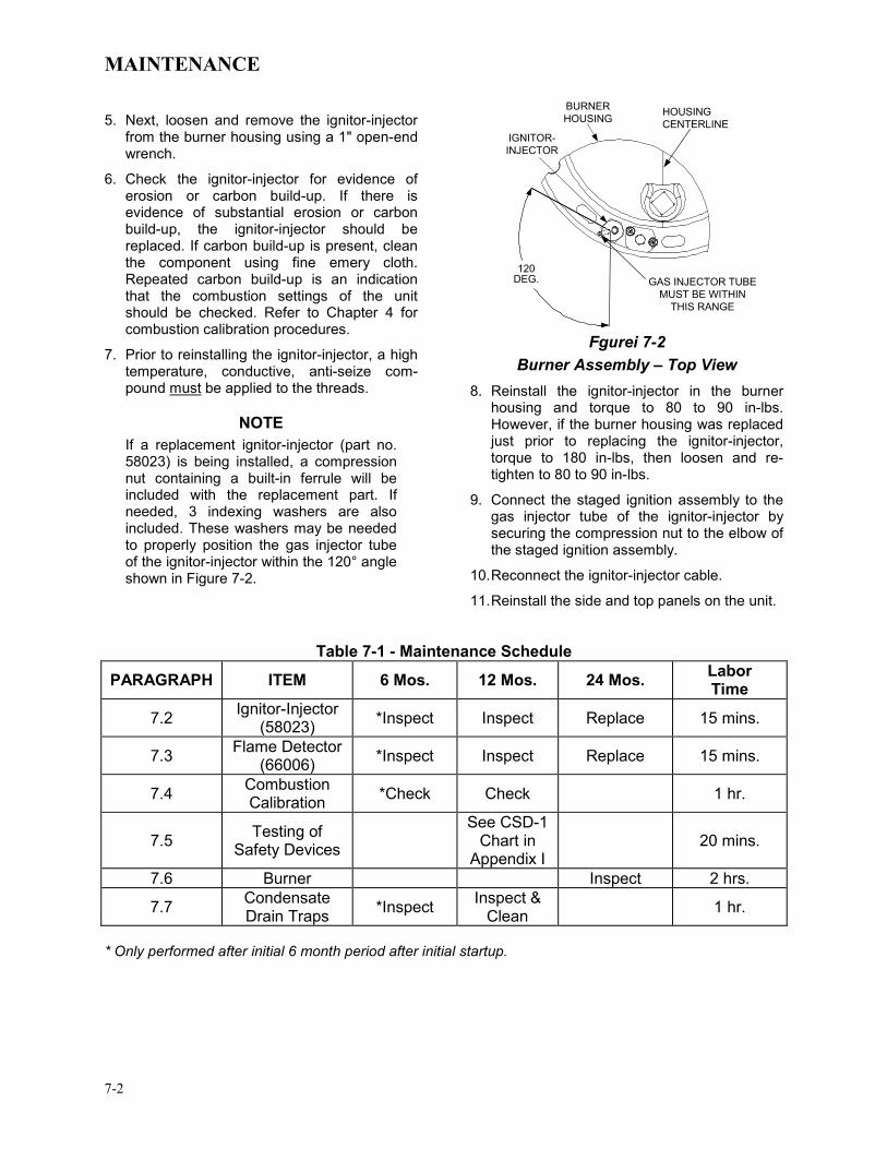
MAINTENANCE
7-2
5. Next, loosen and remove the ignitor-injector from the burner housing using a 1" open-end wrench.
6. Check the ignitor-injector for evidence of erosion or carbon build-up. If there is evidence of substantial erosion or carbon build-up, the ignitor-injector should be replaced. If carbon build-up is present, clean the component using fine emery cloth. Repeated carbon build-up is an indication that the combustion settings of the unit should be checked. Refer to Chapter 4 for combustion calibration procedures.
7. Prior to reinstalling the ignitor-injector, a high temperature, conductive, anti-seize com-pound must be applied to the threads.
NOTE If a replacement ignitor-injector (part no. 58023) is being installed, a compression nut containing a built-in ferrule will be included with the replacement part. If needed, 3 indexing washers are also included. These washers may be needed to properly position the gas injector tube of the ignitor-injector within the 120° angle shown in Figure 7-2.
120
120 DEG. GAS INJECTOR TUBE
MUST BE WITHIN THIS RANGE
IGNITOR-INJECTOR
BURNERHOUSING HOUSING
CENTERLINE
Fgurei 7-2
Burner Assembly – Top View 8. Reinstall the ignitor-injector in the burner
housing and torque to 80 to 90 in-lbs. However, if the burner housing was replaced just prior to replacing the ignitor-injector, torque to 180 in-lbs, then loosen and re-tighten to 80 to 90 in-lbs.
9. Connect the staged ignition assembly to the gas injector tube of the ignitor-injector by securing the compression nut to the elbow of the staged ignition assembly.
10. Reconnect the ignitor-injector cable.
11. Reinstall the side and top panels on the unit.
Table 7-1 - Maintenance Schedule
PARAGRAPH ITEM 6 Mos. 12 Mos. 24 Mos. Labor Time
7.2 Ignitor-Injector (58023) *Inspect Inspect Replace 15 mins.
7.3 Flame Detector (66006) *Inspect Inspect Replace 15 mins.
7.4 Combustion Calibration *Check Check 1 hr.
7.5 Testing of Safety Devices
See CSD-1 Chart in
Appendix I 20 mins.
7.6 Burner Inspect 2 hrs.
7.7 Condensate Drain Traps *Inspect Inspect &
Clean 1 hr.
* Only performed after initial 6 month period after initial startup.

MAINTENANCE
7-3
7.3 FLAME DETECTOR The flame detector, part no. 66006, is located in the body of the burner (see Figure 7-1). The flame detector may be HOT. Allow the unit to cool sufficiently before removing the flame detector.
To inspect or replace the flame detector:
1. Set the ON/OFF switch on the control panel, to the OFF position. Disconnect AC power from the unit.
2. Remove the top panels from the unit.
3. Disconnect the lead wire from the flame detector.
4. Remove the two (2) screws securing the flame detector to the burner housing (Figure 7-1). The flame detector is secured to the burner housing with one (1) #10-32 screw and one (1) #8-32 screw.
5. Remove the flame detector and gasket from the burner housing.
6. Inspect the detector thoroughly. If eroded, the detector should be replaced. Otherwise clean the detector with a fine emery cloth.
7. Reinstall the flame detector and flame detector gasket.
8. Reconnect the flame detector lead wire.
9. Reinstall the top and side panels on the unit.
7.4 COMBUSTION CALIBRATION Combustion settings must be checked at the intervals shown in Table 7-1 as part of the maintenance requirements. Refer to Chapter 4 for combustion calibration instructions.
7.5 SAFETY DEVICE TESTING Systematic and thorough tests of the operating and safety devices should be performed to ensure that they are operating as designed. Certain code requirements, such as ASME CSD-1, require that these tests be performed on a scheduled basis. Test schedules must conform to local jurisdictions. The results of the tests should be recorded in a log book. See Chapter 6-Safety Device Testing Procedures.
7.6 BURNER ASSEMBLY INSPECTION The burner assembly is located at the top front of the unit. The burner assembly may be hot. Allow the unit to cool sufficiently before removing the burner assembly.
The following replacement parts will be necessary for reassembly following inspection:
Part No. Description 81030 Burner Gaskets (Qty=2) 81048 Flame Detector Gasket
To inspect or replace the burner assembly:
1. Set the ON/OFF switch on the control panel, to the OFF position. Disconnect AC power from the unit and turn off the gas supply.
2. Remove the side and top panels from the unit.
3. Disconnect the lead wire from the flame detector (see Figure 7-1).
4. Remove the two (2) screws securing the flame detector to the burner housing. The flame detector is secured to the burner housing with one (1) #10-32 screw and one (1) #8-32 screw.
5. Remove the flame detector and gasket from the burner housing.
6. Disconnect the cable from the ignitor-injector.
7. Using a 7/16” open-end wrench, disconnect the compression nut securing the gas injector tube of the ignitor-injector to the elbow of the staged ignition assembly. Disconnect the staged ignition assembly from the ignitor-injector.
8. Loosen and remove the ignitor-injector from the burner plate using a 1" wrench.
9. Disconnect the burner housing from the blower by removing the six (6) 1/4-20 screws using a 3/8” wrench.
10. Remove the eight (8) 3/8-16 nuts from the burner flange (Figure 7-3) using a 9/16” wrench.

MAINTENANCE
7-4
STAGED IGNITION ASSEMBLY
3/8-16 NUTS (8)
BURNERHOUSING
1/4-20 SCREWS
(6)
GROUNDINGSCREW
Figure 7-3
Burner Disassembly Diagram - Top View
NOTE The burner housing is heavy, weighing approximately 25 pounds.
11. Refer to the exploded view in Figure 7-4. Remove the burner housing from burner flange by pulling straight up.
12. Remove the grounding screw.
13. Remove the burner by pulling straight up.
14. Remove and replace the burner gaskets.
15. Beginning with the burner removed in step 13, reinstall all the components in the reverse order that they were removed.
16. Make sure to align the burner housing with the blower and the heat exchanger top head.
17. Check to ensure that the grounding screw is reinstalled. Also, ensure that conductive, high-temperature, anti-seize compound is applied to the threads of the ground screw and the ignitor-injector. Torque the ignitor-injector to 80 to 90 in-lbs. However, if the burner housing was replaced during inspection, torque to 180 in-lbs, then loosen and re-tighten to 80 to 90 in-lbs.
IGNITOR-INJECTOR
FLAME DETECTOR
STAGED IGNITION ASSEMBLY
BURNER GASKET
BURNER
BURNER GASKET
BURNER HOUSING
Figure 7-4 Burner Assembly - Exploded View
7.7 CONDENSATE DRAIN TRAPS The Benchmark 3.0 Boiler contains two condensate traps as shown in Chapter 2, Figure 2-5. One trap is located external to the unit and attached to the drain pipe from the connecting manifold. The other trap is an integral part of the exhaust manifold. These traps should be inspected and, if necessary, cleaned to ensure proper operation. Follow the procedures in paragraphs 7.7.1 and 7.7.2.
7.7.1 Connecting Manifold Condensate Trap To inspect and clean the condensate trap (part no. 24060) attached to the connecting manifold, proceed as follows:
1. Loosen the thumbscrew securing the trap adaptor (Figure 2-6) to the condensate drain pipe on the connecting manifold.
2. Remove the nipples and connections on the inlet and outlet sides of the condensate trap shown in Figure 7-5.

MAINTENANCE
7-5
3. Loosen the four (4) thumbscrews securing the cover on the condensate trap. Remove the cover.
4. Remove the float from the condensate trap.
5. Remove the orifice gasket from the trap.
6. Thoroughly clean the trap, float and gasket. Also inspect the drain piping for blockage. If the trap cannot be thoroughly cleaned, replace the trap.
7. After the above items have been inspected and thoroughly cleaned, replace the orifice gasket and float in the condensate trap and replace the trap cover.
8. Reassemble all piping and hose connections to the condensate trap inlet and outlet.
9. Reconnect the condensate trap adaptor to connecting manifold drain pipe, Ensure that the trap is level and then tighten the adaptor thumbscrew. Place a suitable support under the trap to maintain it in the level position.
FLOAT
THUMBSCREWS
(4)
3/4 NPTPORT
INLET
OUTLET
3/4 NPTPORT
COVER
O-RING
ORIFICEGASKET
Figure 7-5
External Condensate Trap
7.7.2 Exhaust Manifold Condensate Trap The exhaust manifold condensate trap also contains a float and orifice gasket similar to those shown in Figure 7-5. The only difference is that the orifice gasket in the exhaust manifold trap has a 0.75" I.D. opening and the gasket shown in Figure 7-5 has a 0.25" I.D. To inspect and clean the trap, refer to Figure 7-6 and proceed as follows:
1. Loosen the clamp securing the hose to the condensate drain (Figure 7-6). Disconnect the hose.
2. Remove the four bolts securing the flue to the top of the exhaust manifold. Separate the flue from the exhaust manifold.
3. From the top of the exhaust manifold, remove the float and orifice gasket from the condensate trap.
4. Thoroughly clean the trap, float and gasket. Also, inspect the drain hose for blockage.
5. After the above items have been inspected and cleaned, replace the gasket and float in the condensate trap.
6. Replace the four bolts securing the flue to the exhaust manifold and connect the hose to the manifold condensate drain.
UNITFRAME
EXHAUSTMANIFOLD
CONDENSATETRAP
DRAIN
HOSECLAMP
1" I.D.HOSE
TO FLOORDRAIN
BOLTS(4)
FLUE
Figure 7-6 Exhaust Manifold Condensate Trap &
Drain

MAINTENANCE
7-6
7.8 SHUTTING THE BOILER DOWN FOR AN EXTENDED PERIOD OF TIME If the boiler is to be taken out of service for an extended period of time (one year or more), the following instructions must be followed.
1. Set ON/OFF switch on the front panel to the OFF position to shut down the boiler’s operating controls.
2. Disconnect AC power from the unit.
3. Close the water supply and return valves to isolate boiler.
4. Close external gas supply valve.
5. Open relief valve to vent water pressure.
7.9 PLACING THE BOILER BACK IN SERVICE AFTER A PROLONGED SHUTDOWN After a prolonged shutdown (one year or more), the following procedures must be followed:
1. Review installation requirements included in Chapter 2.
2. Inspect all piping and connections to the unit.
3. Inspect exhaust vent, air duct (if applicable).
4. Perform initial startup per Chapter 4.
5. Perform safety device testing and the scheduled maintenance procedures per Chapters 6 and 7 of this manual.
TROUBLESHOOTING
8-1
Chapter 8- TROUBLESHOOTING GUIDE 8.1 INTRODUCTION This troubleshooting guide is intended to aid service/maintenance personnel in isolating the cause of a fault in a Benchmark 3.0 Boiler. The troubleshooting procedures contained herein are presented in tabular form on the following pages. These tables are comprised of three columns labeled: Fault Indication, Probable Cause and Corrective Action. The numbered items in the Probable Cause and Corrective Action columns correspond to each other. For example, Probable Cause No. 1 corresponds to Corrective Action No. 1, etc.
NOTE: The front panel of the C-More Control Box contains an RS232 port which can be interfaced to a laptop computer or other suitable device. This RS232 communication feature permits service personnel to view menu items and data logs which can be useful in isolating faults. Refer to Chapter 9 of this manual for detailed RS232 communication set-up and procedures.
When a fault occurs in the Benchmark Boiler, proceed as follows to isolate and correct the fault: 1. Observe the fault messages displayed in the
Control Box display. 2. Refer to the Fault Indication column in
Troubleshooting Table 8-1 which follows and locate the Fault that best describes the existing conditions.
3. Proceed to the Probable Cause column and
start with the first item (1) listed for the Fault Indication.
4. Perform the checks and procedures listed in
the Corrective Action column for the first Probable Cause candidate.
5. Continue checking each additional Probable
Cause for the existing fault until the fault is corrected.
6. Paragraph 8.2 and Table 8-2 contain
additional troubleshooting information which may apply when no fault message is displayed.
7. If the fault cannot be corrected using the
information provided in the Troubleshooting Tables, contact your local AERCO Representative.

TROUBLESHOOTING
8-2
TABLE 8-1. BOILER TROUBLESHOOTING
FAULT INDICATION PROBABLE CAUSES CORRECTIVE ACTION AIRFLOW FAULT
DURING IGNITION 1. Blower stopped running due to thermal
or current overload 2. Blocked Blower inlet or inlet ductwork
3. Blocked Blower proof switch
4. Blocked blocked-air inlet switch
5. Defective Blower proof switch
6. Defective blocked-air inlet switch
7. Loose temperature to AUX connection in I/O Box
8. Defective temperature sensor
9. Loose wire connection between the 0-10V signal from I/O box to the Blower Motor input
10. Defective I/O box
11. Wrong 0-10V output selection on the control box
12. Defective Air-Fuel Valve potentiometer
13. Fuel Selector Switch set to incorrect position for fuel used.
1. Check combustion blower for signs of excessive heat or high current drain that may trip thermal or current overload devices.
2. Inspect the inlet to the combustion blower including any ductwork leading up to the combustion blower for signs of blockage.
3. Remove the Blower proof switch and inspect for signs of blockage, clean or replace as necessary.
4. Remove the blocked-air inlet switch and inspect for signs of blockage, clean or replace as necessary.
5. Measure the Blower proof switch for continuity with the combustion blower running. If there is an erratic resistance reading or the resistance reading is greater than zero ohms, replace the switch.
6. Measure the blocked-air inlet switch for continuity with the combustion blower running. If there is an erratic resistance reading or the resistance reading is greater than zero ohms, replace the switch.
7. Check the actual inlet air temperature and measure voltage at AUX input in the I/O Box. Verify that the voltage conforms to the values shown in the tabular listing provided in Appendix C.
8. Refer to CORRECTIVE ACTION 7 and verify that the voltage conforms to the values shown in Appendix C.
9. Check wire connection from I/O Box 0-10V signal to the Blower Motor.
10. Measure voltage at the I/O box 0-10V output. A voltage of 8.2V equates to a 100% valve position.
11. Check the Analog Out option on the C-More Configuration Menu. Valve Position 0-10V should be selected.
12. Check Air/Fuel Valve position at 0%, 50% and 100%. the position on the C-More VALVE POSITION bargraph should match the valve position dial on the Air/Fuel Valve.
13. Check position of Fuel Selector Switch

TROUBLESHOOTING
8-3
TABLE 8-1. BOILER TROUBLESHOOTING – Continued
FAULT INDICATION PROBABLE CAUSES CORRECTIVE ACTION AIRFLOW FAULT DURING PURGE
1. Blower not running or running too slow
2. Defective Air Flow Switch
3. Blocked Air flow Switch
4. Blocked Blower inlet or inlet ductwork.
5. No voltage to switch from control box.
6. PROBABLE CAUSES from 3 to 12 for AIRFLOW FAULT DURING IGNITION applies for this fault.
1. Start the unit. If the blower does not run check the blower solid state relay for input and output voltage. If the relay is okay, check the blower.
2. Start the unit. If the blower runs, check the airflow switch for continuity. Replace the switch if there is no continuity.
3. Remove the air flow switch and inspect for signs of blockage, clean or replace as necessary.
4. Inspect the inlet to the combustion blower including any ductwork leading up to the combustion blower for signs of blockage.
5. Measure for 24 VAC during start sequence from each side of the switch to ground. If 24VAC is not present refer to qualified service personnel.
6. See CORRECTIVE ACTION from 3 to 12 for AIRFLOW FAULT DURING IGNITION
AIRFLOW FAULT DURING RUN
1. Blower stopped running due to thermal or current overload
2. Blocked Blower inlet or inlet ductwork
3. Blocked airflow switch
4. Defective airflow switch
5. Combustion oscillations
6. PROBABLE CAUSES from 3 to 12 for AIRFLOW FAULT DURING IGNITION apply for this fault
7. Unit set for propane operation, but Max Valve Position was not changed to 75%.
1. Check combustion blower for signs of excessive heat or high current draw that may trip thermal or current overload devices.
2. Inspect the inlet to the combustion blower including any ductwork leading up to the combustion blower for signs of blockage.
3. Remove the airflow switch and inspect for signs of blockage, clean or replace as necessary.
4. Measure the airflow switch for continuity with the combustion blower running. If there is an erratic resistance reading or the resistance reading is greater than zero ohms, replace the switch.
5. Run unit to full fire. If the unit rumbles or runs rough, perform combustion calibration.
6. PROBABLE CAUSES from 3 to 12 for AIRFLOW FAULT DURING IGNITION apply for this fault.
7. Check Max Valve Position setting in Configuration Menu.

TROUBLESHOOTING
8-4
TABLE 8-1. BOILER TROUBLESHOOTING – Continued
FAULT INDICATION PROBABLE CAUSES CORRECTIVE ACTION DELAYED
INTERLOCK OPEN 1. Delayed Interlock Jumper not
installed or removed. 2. Device proving switch hooked to
interlocks is not closed
1. Check for a jumper properly installed across the delayed interlock terminals in the I/O box.
2. If there are 2 external wires on these terminals, check to see if an end switch for a device such as a pump, louver, etc. is tied these interlocks. Ensure that the device and or its end switch are functional. (jumper may be temporarily installed to test interlock).
DIRECT DRIVE SIGNAL FAULT
1. Direct drive signal is not present: Not yet installed. Wrong polarity. Signal defective at source. Broken or loose wiring.
2. Signal is not isolated (floating). 3. Control Box signal type selection
switches not set for correct signal type (voltage or current).
1. Check I/O Box to ensure signal is hooked up. Hook up if not installed. If installed, check polarity. Measure signal level. Check continuity of wiring between source and boiler.
2. Check signal at source to ensure it is isolated. 3. Check DIP switch on PMC board to ensure it is set correctly for
the type of signal being sent. Check control signal type set in Configuration Menu.
FLAME LOSS DURING IGN
1. Burner Ground Screw not installed or loose.
2. Worn flame detector
3. No spark from Spark Plug
4. Defective Ignition Transformer
5. Defective Ignition/Stepper (IGST) Board
6. Defective SSOV
7. Carbon or other debris on Burner
1. Inspect and install/retighten Burner Ground Screw.
2. Remove and inspect the flame detector for signs of wear. Replace if necessary.
3. Close the internal gas valve in the boiler. Install and arc a spark igniter outside the unit.
4. If there is no spark, check for 120VAC at the primary side to the ignition transformer during the ignition cycle.
5. If 120VAC is not present, the IGST Board in the Control Box may be defective. Refer fault to qualified service personnel.
6. While externally arcing the spark igniter, observe the open/close indicator in the Safety Shut-Off Valve to ensure it is opening. If the valve does not open, check for 120VAC at the valves input terminals. If 120VAC is not present, the IGST board in the Control Box may be defective. Refer fault to qualified service personnel.
7. Remove the burner and inspect for any carbon or debris. Clean and reinstall

TROUBLESHOOTING
8-5
TABLE 8-1. BOILER TROUBLESHOOTING – Continued
FAULT INDICATION PROBABLE CAUSES CORRECTIVE ACTION
(continued) 8. Staged ignition ball valve is closed.
9. Staged ignition solenoid valve doesn’t open.
10. Clogged staged ignition piece.
8. Check position of staged ignition ball valve on gas train. See Figure 8-1 near end of this Chapter.
9. When boiler goes to ignition, listen to the solenoid valve for a clicking sound to ensure it is opening.
10. Remove and inspect staged ignition piece for blockage.
FLAME LOSS DURING RUN
1. Worn Flame Detector or cracked ceramic.
2. Defective Differential Regulator.
3. Poor combustion calibration. 4. Debris on burner.
5. Blocked condensate drain.
1. Remove and inspect the Flame Detector for signs of wear or cracked ceramic. Replace if necessary.
2. Check gas pressure readings using a gauge or manometer into and out of the Air/Fuel Valve to ensure that the gas pressure into and out of the valve is correct.
3. Check combustion calibration. Adjust as necessary. 4. Remove the burner and inspect for any carbon or debris. Clean
and reinstall. 5. Remove blockage in condensate drain.
HEAT DEMAND FAILURE
1. The Heat Demand Relays on the Ignition/Stepper board failed to activate when commanded
2. Relay is activated when not in Demand
1. Press CLEAR button and restart the unit. If the fault persists, replace Ignition/Stepper (IGST) Board.
2. Defective relay. Replace IGST Board.
HIGH EXHAUST TEMPERATURE
1. Defective exhaust sensor.
2. Carboned heat exchanger due to incorrect combustion calibration
1. Measure the actual exhaust temperature and continuity of the exhaust sensor. If the exhaust temperature is less than 475 o F and the exhaust sensor shows continuity replace the sensor.
2. If exhaust temperature is greater than 500 o F, check combustion calibration. Calibrate or repair as necessary.
HIGH GAS
PRESSURE 1. Incorrect supply gas pressure. 2. Defective SSOV Supply Regulator.
1. Check to ensure gas pressure at inlet of SSOV is 2 psig max. 2. If gas supply pressure downstream of SSOV cannot be
lowered, to 1.5” W.C. (see para. 4.3, step 10), the SSOV Supply Regulator may be defective
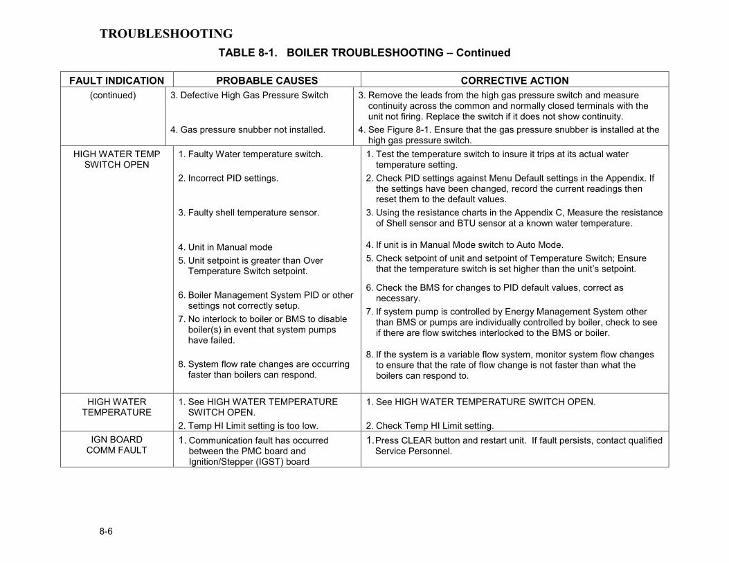
TROUBLESHOOTING
8-6
TABLE 8-1. BOILER TROUBLESHOOTING – Continued FAULT INDICATION PROBABLE CAUSES CORRECTIVE ACTION
(continued) 3. Defective High Gas Pressure Switch
4. Gas pressure snubber not installed.
3. Remove the leads from the high gas pressure switch and measure continuity across the common and normally closed terminals with the unit not firing. Replace the switch if it does not show continuity.
4. See Figure 8-1. Ensure that the gas pressure snubber is installed at the high gas pressure switch.
HIGH WATER TEMP SWITCH OPEN
1. Faulty Water temperature switch.
2. Incorrect PID settings.
3. Faulty shell temperature sensor.
4. Unit in Manual mode 5. Unit setpoint is greater than Over
Temperature Switch setpoint.
6. Boiler Management System PID or other settings not correctly setup.
7. No interlock to boiler or BMS to disable boiler(s) in event that system pumps have failed.
8. System flow rate changes are occurring faster than boilers can respond.
1. Test the temperature switch to insure it trips at its actual water temperature setting.
2. Check PID settings against Menu Default settings in the Appendix. If the settings have been changed, record the current readings then reset them to the default values.
3. Using the resistance charts in the Appendix C, Measure the resistance of Shell sensor and BTU sensor at a known water temperature.
4. If unit is in Manual Mode switch to Auto Mode. 5. Check setpoint of unit and setpoint of Temperature Switch; Ensure
that the temperature switch is set higher than the unit’s setpoint.
6. Check the BMS for changes to PID default values, correct as necessary.
7. If system pump is controlled by Energy Management System other than BMS or pumps are individually controlled by boiler, check to see if there are flow switches interlocked to the BMS or boiler.
8. If the system is a variable flow system, monitor system flow changes to ensure that the rate of flow change is not faster than what the boilers can respond to.
HIGH WATER TEMPERATURE
1. See HIGH WATER TEMPERATURE SWITCH OPEN.
2. Temp HI Limit setting is too low.
1. See HIGH WATER TEMPERATURE SWITCH OPEN.
2. Check Temp HI Limit setting. IGN BOARD
COMM FAULT 1. Communication fault has occurred
between the PMC board and Ignition/Stepper (IGST) board
1. Press CLEAR button and restart unit. If fault persists, contact qualified Service Personnel.

TROUBLESHOOTING
8-7
TABLE 8-1. BOILER TROUBLESHOOTING – Continued
FAULT INDICATION PROBABLE CAUSES CORRECTIVE ACTION IGN SWTCH CLOSED
DURING PURGE 1. Air/Fuel Valve not rotating
2. Defective or shorted switch
3. Switch wired incorrectly
4. Defective Power Supply Board or fuse
5. Defective IGST Board
1. Start the unit. The Air/Fuel Valve should rotate to the purge (open) position. If the valve does not rotate at all or does not rotate fully open, check the Air/Fuel Valve calibration. If calibration is okay, the problem may be in the Air-Fuel Valve or the Control Box. Refer to qualified service personnel
2. . If the Air/Fuel Valve does rotate to purge, check the ignition switch for continuity between the N.O. and COM terminals. If the switch shows continuity when not in contact with the cam replace the switch.
3. Check to ensure that the switch is wired correctly (correct wire numbers on the normally open terminals). If the switch is wired correctly, replace the switch
4. Check DS1 & DS2 LEDs on Power Supply Board. If they are not steady ON, replace Power Supply Board.
5. Check “Heartbeat” LED DS1 and verify it is blinking ON & OFF every second. If not, replace IGST Board
IGN SWTCH OPEN DURING IGNITION
1. Air/Fuel Valve not rotating to ignition position.
2. Defective ignition switch
3. Defective Power Supply Board or fuse
4. Defective IGST Board
1. Start the unit. The Air/Fuel Valve should rotate to the purge (open) position, then back to ignition position (towards closed) during the ignition cycle. If the valve does not rotate back to the ignition position, check the Air/Fuel Valve calibration. If calibration is okay, the problem may be in the Air/Fuel Valve or the Control Box. Refer fault to qualified service personnel.
2. If the Air/Fuel Valve does rotate to the ignition position, check the ignition position switch for continuity between the N.O. and COM terminals when in contact with the cam.
3. Check DS1 & DS2 LEDs on Power Supply Board. If they are not steady ON, replace Power Supply Board.
4. Check “Heartbeat” LED DS1 and verify it is blinking ON & OFF every second. If not, replace IGST Board.

TROUBLESHOOTING
8-8
TABLE 8-1. BOILER TROUBLESHOOTING – Continued
FAULT INDICATION PROBABLE CAUSES CORRECTIVE ACTION INTERLOCK
OPEN 1. Interlock jumper not installed or removed
2. Energy Management System does not have boiler enabled.
3. Device proofing switch hooked up to interlocks is not closed.
1. Check for a jumper properly installed across the interlock terminals in the I/O box
2. If there are two external wires on these terminals check any Energy Management system to see if they have the units disabled (a jumper may be temporarily installed to see if the interlock circuit is functioning).
3. Verify that the proving switch for any device hooked to the interlock circuit is closing and that the device is operational.
LINE VOLTAGE OUT OF PHASE
1. Line and Neutral switched in AC Power Box.
2. Incorrect power supply transformer wiring.
1. Check hot and neutral in AC Power Box to ensure they are not reversed
2. Check transformer wiring, in AC Power Box, against the power box transformer wiring diagram to ensure it is wired correctly
LOW GAS PRESSURE
1. Incorrect supply gas pressure.
2. Defective Low Pressure Gas Switch
3. Fuel Selector Switch is in the OFF position or was changed while the unit was running.
1. Measure gas pressure upstream of the supply gas regulator with the unit firing. Refer to paragraph 2.7.1 to ensure the gas pressure is correct for the type of fuel and gas train being used.
2. Measure gas pressure at the low gas pressure switch. If it is greater than 2.6” W.C., measure continuity across the switch and replace if necessary.
3. Check Fuel Selector Switch position.
LOW WATER
LEVEL 1. Insufficient water level in system 2. Defective water level circuitry.
3. Defective water level probe.
1. Check system for sufficient water level. 2. Test water level circuitry using the Control Box front panel LOW
WATER TEST and RESET buttons. Replace water level circuitry if it does not respond.
3. Check continuity of probe end to the shell, change probe if there is no continuity.
MODBUS COMM FAULT
1. Boiler not seeing information from Modbus network.
1. Check network connections. If fault persists, contact qualified Service Personnel.
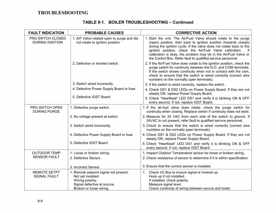
TROUBLESHOOTING
8-9
TABLE 8-1. BOILER TROUBLESHOOTING – Continued
FAULT INDICATION PROBABLE CAUSES CORRECTIVE ACTION PRG SWTCH CLOSED
DURING IGNITION 1. A/F Valve rotated open to purge and did
not rotate to ignition position
2. Defective or shorted switch.
3. Switch wired incorrectly. 4. Defective Power Supply Board or fuse
5. Defective IGST Board
1. Start the unit. The Air/Fuel Valve should rotate to the purge (open) position, then back to ignition position (towards closed) during the ignition cycle. If the valve does not rotate back to the ignition position, check the Air/Fuel Valve calibration. If calibration is okay, the problem may be in the Air/Fuel Valve or the Control Box. Refer fault to qualified service personnel.
2. If the Air/Fuel Valve does rotate to the ignition position, check the purge switch for continuity between the N.O. and COM terminals. If the switch shows continuity when not in contact with the cam, check to ensure that the switch is wired correctly (correct wire numbers on the normally open terminals).
3. If the switch is wired correctly, replace the switch. 4. Check DS1 & DS2 LEDs on Power Supply Board. If they are not
steady ON, replace Power Supply Board. 5. Check “Heartbeat” LED DS1 and verify it is blinking ON & OFF
every second. If not, replace IGST Board. PRG SWTCH OPEN
DURING PURGE 1. Defective purge switch.
2. No voltage present at switch.
3. Switch wired incorrectly.
4. Defective Power Supply Board or fuse
5. Defective IGST Board
1. If the air-fuel valve does rotate, check the purge switch for continuity when closing. Replace switch if continuity does not exist.
2. Measure for 24 VAC from each side of the switch to ground. If 24VAC is not present, refer fault to qualified service personnel.
3. Check to ensure that the switch is wired correctly (correct wire numbers on the normally open terminals).
4. Check DS1 & DS2 LEDs on Power Supply Board. If they are not steady ON, replace Power Supply Board.
5. Check “Heartbeat” LED DS1 and verify it is blinking ON & OFF every second. If not, replace IGST Board.
OUTDOOR TEMP SENSOR FAULT
1. Loose or broken wiring. 2. Defective Sensor.
3. Incorrect Sensor.
1. Inspect Outdoor Temperature sensor for loose or broken wiring. 2. Check resistance of sensor to determine if it is within specification.
3. Ensure that the correct sensor is installed.
REMOTE SETPT SIGNAL FAULT
1. Remote setpoint signal not present: Not yet installed. Wrong polarity. Signal defective at source. Broken or loose wiring.
1. Check I/O Box to ensure signal is hooked up. Hook up if not installed. If installed, check polarity. Measure signal level. Check continuity of wiring between source and boiler.
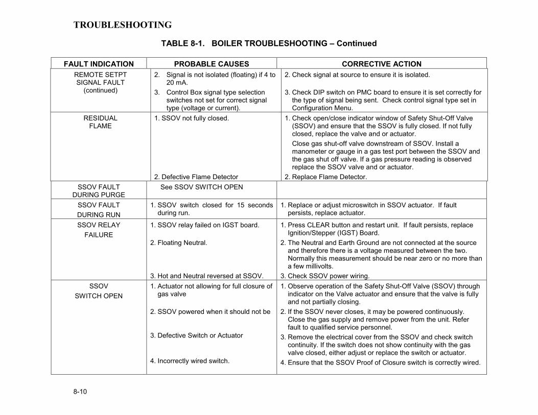
TROUBLESHOOTING
8-10
TABLE 8-1. BOILER TROUBLESHOOTING – Continued
FAULT INDICATION PROBABLE CAUSES CORRECTIVE ACTION REMOTE SETPT SIGNAL FAULT
(continued)
2. Signal is not isolated (floating) if 4 to 20 mA.
3. Control Box signal type selection switches not set for correct signal type (voltage or current).
2. Check signal at source to ensure it is isolated.
3. Check DIP switch on PMC board to ensure it is set correctly for the type of signal being sent. Check control signal type set in Configuration Menu.
RESIDUAL FLAME
1. SSOV not fully closed.
2. Defective Flame Detector
1. Check open/close indicator window of Safety Shut-Off Valve (SSOV) and ensure that the SSOV is fully closed. If not fully closed, replace the valve and or actuator. Close gas shut-off valve downstream of SSOV. Install a manometer or gauge in a gas test port between the SSOV and the gas shut off valve. If a gas pressure reading is observed replace the SSOV valve and or actuator.
2. Replace Flame Detector. SSOV FAULT
DURING PURGE See SSOV SWITCH OPEN
SSOV FAULT DURING RUN
1. SSOV switch closed for 15 seconds during run.
1. Replace or adjust microswitch in SSOV actuator. If fault persists, replace actuator.
SSOV RELAY FAILURE
1. SSOV relay failed on IGST board.
2. Floating Neutral.
3. Hot and Neutral reversed at SSOV.
1. Press CLEAR button and restart unit. If fault persists, replace Ignition/Stepper (IGST) Board.
2. The Neutral and Earth Ground are not connected at the source and therefore there is a voltage measured between the two. Normally this measurement should be near zero or no more than a few millivolts.
3. Check SSOV power wiring. SSOV
SWITCH OPEN 1. Actuator not allowing for full closure of
gas valve
2. SSOV powered when it should not be
3. Defective Switch or Actuator
4. Incorrectly wired switch.
1. Observe operation of the Safety Shut-Off Valve (SSOV) through indicator on the Valve actuator and ensure that the valve is fully and not partially closing.
2. If the SSOV never closes, it may be powered continuously. Close the gas supply and remove power from the unit. Refer fault to qualified service personnel.
3. Remove the electrical cover from the SSOV and check switch continuity. If the switch does not show continuity with the gas valve closed, either adjust or replace the switch or actuator.
4. Ensure that the SSOV Proof of Closure switch is correctly wired.

TROUBLESHOOTING
8-11
TABLE 8-1. BOILER TROUBLESHOOTING – Continued
FAULT INDICATION PROBABLE CAUSES CORRECTIVE ACTION
STEPPER MOTOR FAILURE
1. Air/Fuel Valve out of calibration.
2. Air/Fuel Valve unplugged. 3. Loose wiring connection to the
stepper motor. 4. Defective Air/Fuel Valve stepper
motor. 5. Defective Power Supply Board or fuse
6. Defective IGST Board
1. Refer to GF-112 and perform Stepper Test (para. 6.3.5) to ensure stepper motor rotates properly between the 0% (fully closed) and 100% (fully open) positions. Verify that the VALVE POSITION bargraph and the dial on the Air/Fuel Valve track each other to indicate proper operation. If operation is not correct, perform the Stepper Feedback Calibration (GF-112, para. 6.2.1).
2. Check that the Air/Fuel Valve is connected to the Control Box. 3. .Inspect for loose connections between the Air/Fuel Valve motor
and the wiring harness. 4. Replace stepper motor.
5. Check DS1 & DS2 LEDs on Power Supply Board. If they are not
steady ON, replace Power Supply Board. 6. Check “Heartbeat” LED DS1 and verify it is blinking ON & OFF
every second. If not, replace IGST Board.

TROUBLESHOOTING
8-12
8.2 ADDITIONAL FAULTS WITHOUT SPECIFIC FAULT MESSAGES Refer to Table 8-2 to troubleshoot faults which may occur without a specific fault message being displayed.
TABLE 8-2. BOILER TROUBLESHOOTING WITH NO FAULT MESSAGE DISPLAYED
OBSERVED INCIDENT PROBABLE CAUSES CORRECTIVE ACTION Hard Light-Off 1. Staged Ignition Ball Valve closed.
2. Clogged/damaged Ignitor-Injector
(Figure 8-2). 3. Defective Staged Ignition Solenoid
(Figure 8-2)
1. Open the Staged Ignition 1/4” Ball Valve on the downstream side of the Natural Gas SSOV (see Figure 8-1).
2. Disconnect and inspect gas injector to ensure it is not clogged or damaged.
3. Close the 2” Shutoff Valve and the Staged Ignition 1/4” Ball Valve on the downstream side of the Natural Gas SSOV (see Figure 8-1). Start the unit and listen for a “clicking” sound that the Staged Ignition Solenoid makes during Ignition Trial. If “clicking” sound is not heard after 2 or 3 attempts, replace the Staged Ignition Solenoid.
Fluctuating Gas Pressure 1. Gas pressure going into unit is fluctuating.
2. Damping Orifice not installed.
1. Stabilize gas pressure going into unit. If necessary, troubleshoot Building Supply Regulator.
2. Check to ensure that the Damping Orifice is installed in the Propane SSOV, or Natural Gas SSOV depending on the type of fuel being used (Figure 8-3).
Air/Fuel Valve “hunting” at 80% Valve Position
1. IGST and Power Supply Boards in Control Box are outdated.
1. Check to ensure that the IGST and Power Supply Boards are Rev. E or higher.

TROUBLESHOOTING
8-13
Figure 8-1
High Pressure Gas Switch & Snubber Locations
IGNITOR-INJECTOR
FLAME DETECTOR
STAGED IGNITION ASSEMBLY
BURNER HOUSING
Figure 8-2
Staged Ignition Solenoid Location
NATURALGAS SSOV
PROPANESSOV
DAMPINGORIFICE
PROPANE
NAT. GAS
Figure 8-3
Damping Orifice Location


RS232 COMMUNICATION
9-1
CHAPTER 9 RS232 COMMUNICATION 9.1 INTRODUCTION The RS232 port on the front panel of the C-More Control Box (Figure 3-1) can be interfaced to a laptop computer or other suitable terminal using a RS232 adapter cable. RS232 communication can be accomplished using any “Dumb Terminal” emulation, such as “Hyper Terminal” which is included with Microsoft Windows. The RS232 communication feature permits viewing or changing of Control Panel menu options and also provides access to data logs showing Event Time Line, Fault and Sensor log displays.
9.2 RS232 COMMUNICATION SETUP Regardless of the terminal emulation utilized, the following guidelines must be adhered to when setting up the RS232 communication link:
1. Baud Rate – The baud rates which can be used with the C-More Control Panel are:
2400 4800 9600 (Default) 19.2K
2. Data Format – The program must be set for: 8 data bits, 1 stop bit, no parity and either Xon/Xoff or No flow control.
9.3 MENU PROCESSING UTILIZING
RS232 COMMUNICATION Viewing data logs and viewing or changing Control Panel menu options using RS232 communication is accomplished as follows:
1. Start the emulator software program and ensure that the specified baud rate and data formats have been entered.
2. Press the Enter key on the laptop. An asterisk (*) prompt should appear.
3. At the prompt, enter the valid RS232 password (jaguar) in lower case letters and press Enter.
4. “Welcome to Aerco” will appear in the laptop or “dumb terminal” display with a listing of the following available entry choices:
M = Display next Menu D = Display menu items N = Display next menu items Cxx = Change item xx
F = Fault log display S = Sensor log display T = Time line display L = Log off
NOTE: The Level 1 password (159) must be entered to change options in the Setup, Configuration and Tuning Menus. The Level 2 password (6817) must be entered to view or change options in the Calibration and Diagnostics Menus. With the exception of the password entry, all other keyboard entries can be made using either upper or lower case.
5. To view the available menus in the top-down sequence shown in Figure 3-2, enter M <Rtn>. The Menu title and first 10 options will be displayed.
6. When viewing menus containing more than 10 options, enter N <Rtn> to display the remaining options.
7. Shortcut keys are also available to go directly to a specific menu. These shortcut keys are:
m0 Default (Operating) Menu m1 Setup Menu m2 Configuration Menu m3 Tuning Menu m4 Calibration Menu m5 Diagnostic Menu
8. To change a value or setting for a displayed menu option, proceed as follows:
(a) Enter C, followed by the number to the right of the displayed option to be changed, and then press <Rtn>.
(b) Enter the desired value or setting for the option and press <Rtn>. Refer to Chapter 3, Tables 3-2 through 3-5 for allowable entry ranges and settings for the Operating, Setup, Configuration and Tuning Menus. (The Calibration and Diagnostic Menus should only be used by Factory-Trained service personnel).
(c) Menu changes will be stored in non-volatile memory.
9. To redisplay the menu and view the option which was just changed in step 5, enter D and press <Rtn>.

RS232 COMMUNICATION
9-2
10. To display the Fault (F) Log, Sensor (S) Log or Time (T) Line Log, press F, S or T followed by <Rtn>. Refer to paragraph 9.4 for descriptions and samples of these data logs.
11. To log off and terminate the RS232 com-munication link, press L followed by <Rtn>.
9.4 DATA LOGGING During operation, the C-More Control Panel continuously monitors and logs data associated with operational events, faults and sensor readings associated with the boiler or water heater system. Descriptions of these data logs are provided in the following paragraphs. The basic procedure for accessing each data log is described in paragraph 9.3, step 7.
9.4.1 Fault Log The C-More Control Panel logs the last 20 faults (0 – 19) starting with the most recent (#0). They can be viewed in the front panel display or via the RS232 port. The Fault Log cannot be cleared. If the Fault Log already contains 10 faults, the earliest fault is overwritten when a new fault occurs. A sample Fault Log display is shown in Table 9-1.
NOTE: The Operation Time (T) Log can store thousands of records. Therefore, to view the most recently logged record, enter “T” followed by 0 (zero) and press Enter (i.e. T0 <Enter>). To view earlier records in reverse chronological order, enter T and press Enter. To go back 200 or 1000 records, enter T200 or T1000, etc. and press Enter.
9.4.2 Operation Time Log The Operation Time Log consists of a string of ASCII records stored in non-volatile memory within the C-More Control Panel. Events such
as power-up, ignition and turn-off are time stamped. Data logged while the unit is running are run-length encoded. Data is logged or the run-length incremented every 30 seconds. For a new run record to be logged, the fire rate or flame strength must change by more than 5%, or the run mode must change. At steady-state, the run-length is allowed to reach a maximum of 30 minutes before the record is logged. This means that no more than 30 minutes of data can be lost if the unit loses power. Table 9-2 shows a sample Operation Time Log for a boiler:
The Operation Time Log can only be accessed through the RS232 interface using a laptop or other terminal device. Ten operation time records are displayed for each T command entry. The operation time log can be cleared ONLY by factory authorized personnel using the Clear Log option in the Factory menu.
NOTE: The Sensor (S) Log can store up to 1200 records. Therefore, to view the most recently logged record, enter “S” followed by 0 (zero) and then press Enter (i.e. S0 <Enter>). To view earlier records in reverse chronological order, enter S and press Enter. To go back 200 or 700 records, enter S200 or S700, etc. and press Enter.
9.4.3 Sensor Log The sensor values can be logged at a different rate if needed by setting the Sensor Log Interval in the Diagnostics Menu. The log interval can vary from once every minute to once every day. Table 9-3 shows a sample Sensor Log every 5 minutes for a boiler running in Constant Setpoint mode.

RS232 COMMUNICATION
9-3
Table 9-1. Sample Fault Log Display
No. Fault Message Cycle Date Time 0 Direct Drive Signal Fault 609 1/10/02 8:42am 1 Low Gas Pressure 366 7/04/01 5:29pm 2 Loss of Power 0 1/01/01 11:50am
Table 9-2. Sample Operation Time Log Display
Status Fire Rate Flame Run Length Date Time Off, Direct Drive 0 0 8 1/15/02 2:35pm Run, Direct Drive 38 100 34 1/15/02 2:27pm Run, Direct Drive 31 100 30 1/15/02 1:53am Run, Direct Drive 35 100 2 1/15/02 1:23pm Run, Direct Drive 29 100 0 1/15/02 1:21pm Ignition 0 0 0 1/15/02 1:20pm Off, Switch 0 0 35 1/15/02 12:30pm Run, Manual 40 100 0 1/15/02 11:55am Ignition 0 0 0 1/15/02 11:55am Power-up 0 0 0 1/15/02 11:50am
Table 9-3. Sample Sensor Log Display Setpt Outlet Outdr FFWD Aux Inlet Exhst CO O2 Flow Date Time 130 181 OPEN OPEN OPEN OPEN OPEN 0 .0 0 1/15/02 5:51pm 130 180 OPEN OPEN OPEN OPEN OPEN 0 .0 0 1/15/02 5:46pm 130 180 OPEN OPEN OPEN OPEN OPEN 0 .0 0 1/15/02 5:41pm 130 179 OPEN OPEN OPEN OPEN OPEN 0 .0 0 1/15/02 5:36pm 130 180 OPEN OPEN OPEN OPEN OPEN 0 .0 0 1/15/02 5:31pm 130 180 OPEN OPEN OPEN OPEN OPEN 0 .0 0 1/15/02 5:26pm 130 180 OPEN OPEN OPEN OPEN OPEN 0 .0 0 1/15/02 5:21pm 130 180 OPEN OPEN OPEN OPEN OPEN 0 .0 0 1/15/02 5:16pm 130 179 OPEN OPEN OPEN OPEN OPEN 0 .0 0 1/15/02 5:11pm 130 180 OPEN OPEN OPEN OPEN OPEN 0 .0 0 1/15/02 5:06pm

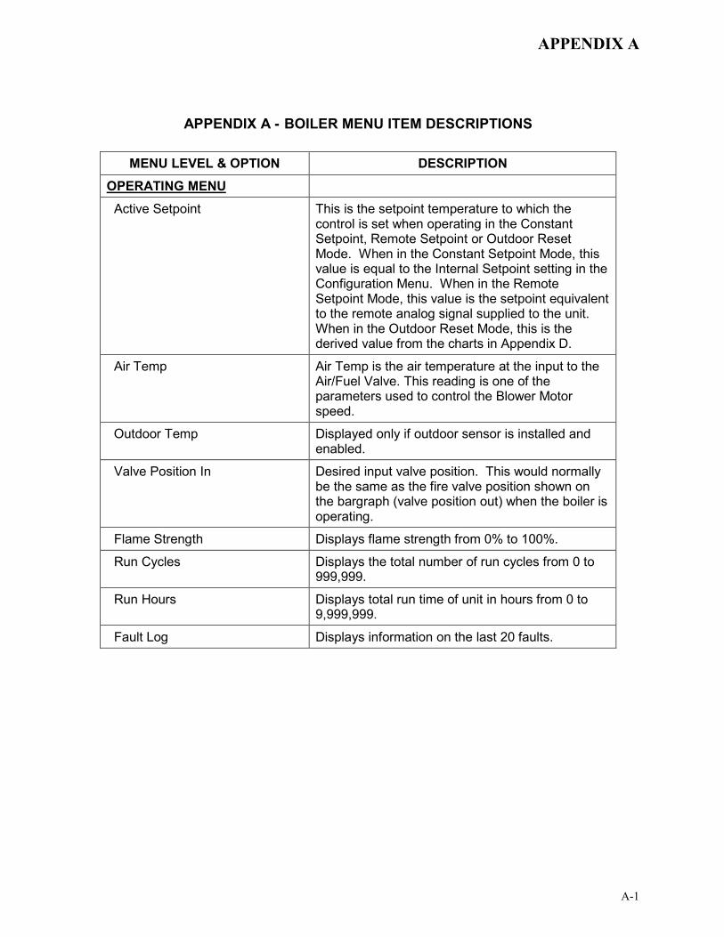
APPENDIX A
A-1
APPENDIX A - BOILER MENU ITEM DESCRIPTIONS
MENU LEVEL & OPTION DESCRIPTION OPERATING MENU Active Setpoint This is the setpoint temperature to which the
control is set when operating in the Constant Setpoint, Remote Setpoint or Outdoor Reset Mode. When in the Constant Setpoint Mode, this value is equal to the Internal Setpoint setting in the Configuration Menu. When in the Remote Setpoint Mode, this value is the setpoint equivalent to the remote analog signal supplied to the unit. When in the Outdoor Reset Mode, this is the derived value from the charts in Appendix D.
Air Temp Air Temp is the air temperature at the input to the Air/Fuel Valve. This reading is one of the parameters used to control the Blower Motor speed.
Outdoor Temp Displayed only if outdoor sensor is installed and enabled.
Valve Position In Desired input valve position. This would normally be the same as the fire valve position shown on the bargraph (valve position out) when the boiler is operating.
Flame Strength Displays flame strength from 0% to 100%.
Run Cycles Displays the total number of run cycles from 0 to 999,999.
Run Hours Displays total run time of unit in hours from 0 to 9,999,999.
Fault Log Displays information on the last 20 faults.

APPENDIX A
A-2
APPENDIX A - BOILER MENU ITEM DESCRIPTIONS - Continued MENU LEVEL & OPTION DESCRIPTION
SETUP MENU
Password Allows password to be entered. Once the valid password (159) is entered, options in the Setup, Configuration and Tuning Menus can be modified.
Language English only
Time Displays time from 12:00 am to 11:59 pm.
Date Displays dates from 01/01/00 to 12/31/99
Unit of Temp Permits selection of temperature displays in degrees Fahrenheit (°F) or degrees Celsius (°C). Default is °F.
Comm Address For RS-485 communications (0 to 127). Default address is 0. RS-232 should have its own (programmable) password.
Baud Rate Allows communications Baud Rate to be set (2400 to 19.2K). Default is 9600.
Software Version Identifies the current software version of the control box (Ver 0.0 to Ver 9.9).
CONFIGURATION MENU
Internal Setpoint Allows internal setpoint to be set . Default is 130°F.
Unit Type Allows selection of KC Boiler, KC Boiler LN, BMK Boiler, BMK Boiler LN, BMK Boiler Dual, KC Water Heater, KC Water Heater LN, Water Heater 2010. Default is BMK Boiler Dual.
Unit Size Sets unit size from 0.5 to 6.0 MBTUs. Default is 3.0 MBTU.
Fuel Type Allows selection of Natural Gas or Propane. Default is Natural Gas.
Boiler Mode It allows selection of: Constant Setpoint, Remote Setpoint, Direct Drive, Combination, or Outdoor Reset Mode. Default is Constant Setpoint Mode.
Remote Signal Used to set the type of external signal which will be used when operating in the Remote Setpoint, Direct Drive or Combination Mode. The factory default is 4-20 mA/1-5V.
Bldg Ref Temp
Allows the building reference temperature to be set when operating a boiler in the Outdoor Reset Mode. Default is 70°F.

APPENDIX A
A-3
APPENDIX A - BOILER MENU ITEM DESCRIPTIONS - Continued
MENU LEVEL & OPTION DESCRIPTION CONFIGURATION MENU (Cont.)
Reset Ratio Permits setting of Reset Ratio when operating boiler in the Outdoor Reset Mode. Reset Ratio is adjustable from 0.1 to 9.9. Default is 1.2.
Outdoor Sensor Allows outdoor sensor function to be enabled or disabled. Default is disabled.
System Start Tmp If outdoor sensor is enabled, this menu item allows the system start temperature to be set from 30 to 100°F. Default is 60°F.
Setpoint Lo Limit Used to set the minimum allowable setpoint (40°F to Setpoint Hi Limit). Default is 60°F
Setpoint Hi Limit Used to set the maximum allowable setpoint (Setpoint Lo Limit to 195°F). Default is 195°F.
Temp Hi Limit This is the maximum allowable outlet temperature (40 to 210°F). Any temperature above this setting will turn off the unit. The temperature must then drop 5° below this setting to allow the unit to run. Default Hi Limit is 195°F.
Max Valve Positon Sets the maximum allowable valve position for the unit (40% to 100%). Default is 100%.
Pump Delay Timer Specifies the amount of time (0 to 30 min.) to keep the pump running after the unit turns off. Default is zero.
Aux Start On Dly Specifies the amount of time to wait (0 to 120 sec.) between activating the Aux Relay (due to a demand) and checking the pre-purge string to start the boiler. Default is 0 sec.
Failsafe Mode Allows the Failsafe mode to be set to either Constant Setpoint or Shutdown. Default is Shutdown.
Analog Output Must be set to Valve Pos 0-10V.
Lo Fire Timer Specifies how long (2 to 600 sec.) to remain in the low fire position after ignition, before going to the desired output. Default is 2 sec.
Network Timeout Specifies the timeout value (seconds) before a Modbus fault is declared. Available settings range from 5 to 999 seconds. Default is 30 seconds.

APPENDIX A
A-4
APPENDIX A - BOILER MENU ITEM DESCRIPTIONS - Continued
MENU LEVEL & OPTION DESCRIPTION CONFIGURATION MENU (Cont.)
HI DB Setpt EN Operating at a Valve Position below this value will inhibit the DEADBAND feature. When operating at a Valve Position below this value, the effective Setpoint is equal to Active Setpoint + DEADBAND HIGH. Setting range is from 0 to 100. (Default is 30)
Demand Offset This entry will reduce excessive ON/OFF cycling in AUTO mode. When this entry is a non-zero value, the unit will not turn on again until Valve Position In reaches the Start Level value AND the Outlet Temperature goes below the Active Setpoint – Demand Offset. In addition, the boiler will fire at the 29% Valve Position level or below for a period of one minute. When this entry is set to zero, the unit will turn on again as soon as the Valve Position in reaches the Start Level value. There will not be a one minute delay when firing at the 29% Valve Position level. Setting range is 0 to 25. (Default is 10)
Deadband High Deadband Low
Deadband High and Deadband Low settings create an “Outlet Temperature” Zone. In which no Valve Position corrections will be attempted. The Deadband ZONE is defined as operating with an Outlet Temperature between Active Setpoint + Deadband High and Active Setpoint – Deadband Low. When the Outlet Temperature reaches Active Setpoint and remains there for a period of 15 seconds, the unit will go into a DEADBAND MODE at which point no Valve Position corrections will be attempted while the Outlet Temperature remains anywhere within the Deadband ZONE. When the unit is in the DEADBAND MODE, the °F or °C LED will flash on and off. When the Outlet Temperature drifts out of the Deadband ZONE, the DEADBAND MODE will be terminated and the PID LOOP will again attempt Valve Position corrections. Setting range is 0 to 25. (Default is 2 for both Deadband High and Deadband Low)

APPENDIX A
A-5
MENU LEVEL & OPTION DESCRIPTION TUNING MENU
Prop Band Generates a fire rate based on the error that exists between the setpoint temperature and the actual outlet temperature. If the actual error is less than the proportional band setting (1 to 120°F), the fire rate will be less than 100%. If the error is equal to or greater than the proportional band setting, the fire rate will be 100%.
Integral Gain This sets the fraction of the output, due to setpoint error, to add or subtract from the output each minute to move towards the setpoint. Gain is adjustable from 0.00 to 1.00 (Default is 0.10).
Derivative Time This value (0.0 to 20.0 min.) responds to the rate of change of the setpoint error. This is the time that this action advances the output.
Reset Defaults? Allows Tuning Menu options to be reset to their Factory Default values.


APPENDIX B
B-1
APPENDIX B - STARTUP, STATUS AND FAULT MESSAGES
TABLE B-1. STARTUP AND STATUS MESSAGES
MESSAGE DESCRIPTION DEMAND DELAY
XX sec Displayed if Demand Delay is active.
DISABLED HH:MM pm, pm
MM/DD/YY
Displayed if ON/OFF switch is set to OFF. The display also shows the time (am or pm) and date that the unit was disabled.
FLAME PROVEN
Displayed after flame has been detected for a period of 2 seconds. Initially, the flame strength is shown in %. After 5 seconds has elapsed, the time and date are shown in place of flame strength.
IGNITION TRIAL XX sec
Displayed during ignition trial of startup sequence. The duration of cycle counts up in seconds.
PURGING XX sec
Displayed during the purge cycle during startup. The duration of the purge cycle counts up in seconds.
STANDBY Displayed when ON/OFF switch is in the ON position, but there is no demand for heat. The time and date are also displayed.
WAIT Prompts the operator to wait. WARMUP
XX sec Displayed for 2 minutes during the initial warm-up only.
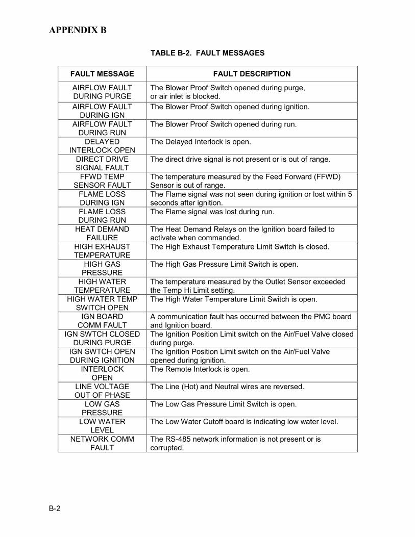
APPENDIX B
B-2
TABLE B-2. FAULT MESSAGES
FAULT MESSAGE FAULT DESCRIPTION
AIRFLOW FAULT DURING PURGE
The Blower Proof Switch opened during purge, or air inlet is blocked.
AIRFLOW FAULT DURING IGN
The Blower Proof Switch opened during ignition.
AIRFLOW FAULT DURING RUN
The Blower Proof Switch opened during run.
DELAYED INTERLOCK OPEN
The Delayed Interlock is open.
DIRECT DRIVE SIGNAL FAULT
The direct drive signal is not present or is out of range.
FFWD TEMP SENSOR FAULT
The temperature measured by the Feed Forward (FFWD) Sensor is out of range.
FLAME LOSS DURING IGN
The Flame signal was not seen during ignition or lost within 5 seconds after ignition.
FLAME LOSS DURING RUN
The Flame signal was lost during run.
HEAT DEMAND FAILURE
The Heat Demand Relays on the Ignition board failed to activate when commanded.
HIGH EXHAUST TEMPERATURE
The High Exhaust Temperature Limit Switch is closed.
HIGH GAS PRESSURE
The High Gas Pressure Limit Switch is open.
HIGH WATER TEMPERATURE
The temperature measured by the Outlet Sensor exceeded the Temp Hi Limit setting.
HIGH WATER TEMP SWITCH OPEN
The High Water Temperature Limit Switch is open.
IGN BOARD COMM FAULT
A communication fault has occurred between the PMC board and Ignition board.
IGN SWTCH CLOSED DURING PURGE
The Ignition Position Limit switch on the Air/Fuel Valve closed during purge.
IGN SWTCH OPEN DURING IGNITION
The Ignition Position Limit switch on the Air/Fuel Valve opened during ignition.
INTERLOCK OPEN
The Remote Interlock is open.
LINE VOLTAGE OUT OF PHASE
The Line (Hot) and Neutral wires are reversed.
LOW GAS PRESSURE
The Low Gas Pressure Limit Switch is open.
LOW WATER LEVEL
The Low Water Cutoff board is indicating low water level.
NETWORK COMM FAULT
The RS-485 network information is not present or is corrupted.

APPENDIX B
B-3
TABLE B-2. FAULT MESSAGES - Continued
FAULT MESSAGE FAULT DESCRIPTION OUTDOOR TEMP SENSOR FAULT
The temperature measured by the Outdoor Air Sensor is out of range.
OUTLET TEMP SENSOR FAULT
The temperature measured by the Outlet Sensor is out of range: • OUTLET TEMPERATURE display = SHt Indicates sensor
is shorted • OUTLET TEMPERATURE display = OPn indicates sensor
is open-circuited PRG SWTCH CLOSED
DURING IGNITION The Purge Position Limit Switch on the Air/Fuel Valve closed during ignition.
PRG SWTCH OPEN DURING PURGE
The Purge Position Limit Switch on the Air/Fuel Valve opened during purge.
REMOTE SETPT SIGNAL FAULT
The Remote Setpoint signal is not present or is out of range.
RESIDUAL FLAME
The Flame signal was seen for more than 60 seconds during standby.
SSOV SWITCH OPEN
The SSOV switch opened during standby.
SSOV FAULT DURING PURGE
The SSOV switch opened during purge.
SSOV FAULT DURING IGN
The SSOV switch closed or failed to open during ignition.
SSOV FAULT DURING RUN
The SSOV switch closed for more than 15 seconds during run.
SSOV RELAY FAILURE
A failure has been detected in one of the relays that control the SSOV.
STEPPER MOTOR FAILURE
The Stepper Motor failed to move the Air/Fuel Valve to the desired position.


APPENDIX C
C-1
TEMPERATURE SENSOR RESISTANCE VOLTAGE CHART (BALCO)
TEMP (°F) RES (OHMS) VOLTS*
-40 -30 -20 -10 0
10 20 30 40 50 60 70 80 90 100 110 120 130 140 150 160 170 180 190 200 210 220 230 240 250
779.0 797.5 816.3 835.4 854.8 874.6 894.7 915.1 935.9 956.9 978.3 1000.0 1022.0 1044.4 1067.0 1090.0 1113.3 1137.0 1160.9 1185.2 1209.5 1234.7 1260.0 1285.6 1311.4 1337.7 1364.2 1391.0 1418.2 1445.7
1.93 1.96 1.99 2.02 2.05 2.07 2.10 2.12 2.15 2.17 2.20 2.23 2.25 2.27 2.30 2.32 2.34 2.36 2.39 2.41 2.43 2.45 2.47 2.50 2.52 2.54 2.56 2.58
*Voltage at AUX & Common terminals in the I/O Box

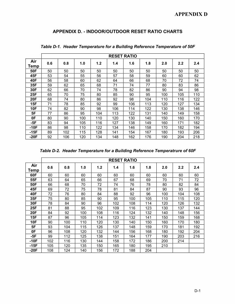
APPENDIX D
D-1
APPENDIX D. - INDOOR/OUTDOOR RESET RATIO CHARTS
Table D-1. Header Temperature for a Building Reference Temperature of 50F
RESET RATIO Air
Temp 0.6 0.8 1.0 1.2 1.4 1.6 1.8 2.0 2.2 2.4
50F 50 50 50 50 50 50 50 50 50 50 45F 53 54 55 56 57 58 59 60 60 62 40F 56 58 60 62 64 66 68 70 72 74 35F 59 62 65 68 71 74 77 80 83 86 30F 62 66 70 74 78 82 86 90 94 98 25F 65 70 75 80 85 90 95 100 105 110 20F 68 74 80 86 92 98 104 110 116 122 15F 71 78 85 92 99 106 113 120 127 134 10F 74 82 90 98 106 114 122 130 138 146 5F 77 86 95 104 113 122 131 140 149 158 0F 80 90 100 110 120 130 140 150 160 170 -5F 83 94 105 116 127 138 149 160 171 182 -10F 86 98 110 122 134 146 158 170 182 194 -15F 89 102 115 128 141 154 167 180 193 206 -20F 92 106 120 134 148 162 176 190 204 218
Table D-2. Header Temperature for a Building Reference Temperatrure of 60F
RESET RATIO Air
Temp 0.6 0.8 1.0 1.2 1.4 1.6 1.8 2.0 2.2 2.4
60F 60 60 60 60 60 60 60 60 60 60 55F 63 64 65 66 67 68 69 70 71 72 50F 66 68 70 72 74 76 78 80 82 84 45F 69 72 75 78 81 84 87 90 93 96 40F 72 76 80 84 88 92 96 100 104 108 35F 75 80 85 90 95 100 105 110 115 120 30F 78 84 90 96 102 108 114 120 126 132 25F 81 88 95 102 109 116 123 130 137 144 20F 84 92 100 108 116 124 132 140 148 156 15F 87 96 105 114 123 132 141 150 159 168 10F 90 100 110 120 130 140 150 160 170 180 5F 93 104 115 126 137 148 159 170 181 192 0F 96 108 120 132 144 156 168 180 192 204 -5F 99 112 125 138 151 164 177 190 203 216 -10F 102 116 130 144 158 172 186 200 214 -15F 105 120 135 150 165 180 195 210 -20F 108 124 140 156 172 188 204

APPENDIX D
D-2
Table D-3. Header Temperature for a Building Reference Temperature of 65F
RESET RATIO Air
Temp 0.6 0.8 1.0 1.2 1.4 1.6 1.8 2.0 2.2 2.4
65 65 65 65 65 65 65 65 65 65 65 60 68 69 70 71 72 73 74 75 76 77 55 71 73 75 77 79 81 83 85 87 89 50 74 77 80 83 86 89 92 95 98 101 45 77 81 85 89 93 97 101 105 109 113 40 80 85 90 95 100 105 110 115 120 125 35 83 89 95 101 107 113 119 125 131 137 30 86 93 100 107 114 121 128 135 142 149 25 89 97 105 113 121 129 137 145 153 161 20 92 101 110 119 128 137 146 155 164 173 15 95 105 115 125 135 145 155 165 175 185 10 98 109 120 131 142 153 164 175 186 197 5 101 113 125 137 149 161 173 185 197 209 0 104 117 130 143 156 169 182 195 208 -5 107 121 135 149 163 177 191 205 219 -10 110 125 140 155 170 185 200 215 -15 113 129 145 161 177 193 209 -20 116 133 150 167 201 218
Table D-4. Header Temperature for a Building Reference Temperature of 70F
RESET RATIO Air
Temp 0.6 0.8 1.0 1.2 1.4 1.6 1.8 2.0 2.2 2.4
70F 70 70 70 70 70 70 70 70 70 70 65F 73 74 75 76 77 78 79 80 81 82 60F 76 78 80 82 84 86 88 90 92 94 55F 79 82 85 88 91 94 97 100 103 106 50F 82 86 90 94 98 102 106 110 114 118 45F 85 90 95 100 105 110 115 120 125 130 40F 88 94 100 106 112 118 124 130 136 142 35F 91 98 105 112 119 126 133 140 147 154 30F 94 102 110 118 126 134 142 150 158 166 25F 97 106 115 124 133 142 151 160 169 178 20F 100 110 120 130 140 150 160 170 180 190 15F 103 114 125 136 147 158 169 180 191 202 10F 106 118 130 142 154 166 178 190 202 214 5F 109 122 135 148 161 174 187 200 213 0F 112 126 140 154 168 182 196 210 -5F 115 130 145 160 175 190 205 -10F 118 134 150 166 182 198 214 -15F 121 138 155 172 189 206 -20F 124 142 160 178 196 214

APPENDIX D
D-3
Table D-5. Header Temperature for a Building Reference Temperature of 75F
RESET RATIO Air
Temp 0.6 0.8 1.0 1.2 1.4 1.6 1.8 2.0 2.2 2.4
75F 75 75 75 75 75 75 75 75 75 75 70F 78 79 80 81 82 83 84 85 86 87 65F 81 83 85 87 89 91 93 95 97 99 60F 84 87 90 93 96 99 102 105 108 111 55F 87 91 95 99 103 107 111 115 119 123 50F 90 95 100 105 110 115 120 125 130 135 45F 93 99 105 111 117 123 129 135 141 17 40F 96 103 110 117 124 131 138 145 152 159 35F 99 107 115 123 131 139 147 155 163 171 30F 102 111 120 129 138 147 156 165 174 183 25F 105 115 125 135 145 155 165 175 185 195 20F 108 119 130 141 152 163 174 185 196 207 15F 111 123 135 147 159 171 183 195 207 219 10F 114 127 140 153 166 179 192 205 218 5F 117 131 145 159 173 187 201 215 0F 120 135 150 165 180 195 210 -5F 123 139 155 171 187 203 219 -10F 126 143 160 177 194 211 -15F 129 147 165 183 201 219
Table D-6. Header Temperature for a Building Reference Temperature of 80F
RESET RATIO Air
Temp 0.6 0.8 1.0 1.2 1.4 1.6 1.8 2.0 2.2 2.4
80F 80 80 80 80 80 80 80 80 80 80 75F 83 84 85 86 87 88 89 90 91 92 70F 86 88 90 92 94 96 98 100 102 104 65F 89 92 95 98 101 104 107 110 113 116 60F 92 96 100 104 108 112 116 120 124 128 55F 95 100 105 110 115 120 125 130 135 140 50F 98 104 110 116 122 128 134 140 146 152 45F 101 108 115 122 129 136 143 150 157 164 40F 104 112 120 128 136 144 152 160 168 176 35F 107 116 125 134 143 152 161 170 179 188 30F 110 120 130 140 150 160 170 180 190 200 25F 113 124 135 146 157 168 174 190 201 212 20F 116 128 140 152 164 176 188 200 212 15F 119 132 145 158 171 184 197 210 10F 122 136 150 164 178 192 206 5F 125 140 155 170 185 200 215 0F 128 144 160 176 192 208 -5F 131 148 165 182 199 216 -10F 134 152 170 188 206

APPENDIX D
D-4
Table D-7. Header Temperature for a Building Reference Temperature of 90F
RESET RATIO
Air Temp
0.6 0.8 1.0 1.2 1.4 1.6 1.8 2.0 2.2 2.4
90F 90 90 90 90 90 90 90 90 90 90 85F 93 94 95 96 97 98 99 100 101 102 80F 96 98 100 102 104 106 108 110 112 114 75F 99 102 105 108 111 114 117 120 123 126 70F 102 106 110 114 118 122 126 130 134 138 65F 105 110 115 120 125 130 135 140 145 150 60F 108 114 120 126 132 138 144 150 156 162 55F 111 118 125 132 139 146 153 160 167 174 50F 114 122 130 138 146 154 162 170 178 186 45F 117 126 135 144 153 162 171 180 189 198 40F 120 130 140 150 160 170 180 190 200 210 35F 123 134 145 156 167 178 189 200 30F 126 138 150 162 174 186 198 210 25F 129 142 155 168 181 194 207 20F 132 146 160 174 188 202 216 15F 135 150 165 180 195 210 10F 138 154 170 186 202 218 5F 141 158 175 192 209 0F 144 162 180 198 216

APPENDIX E
E-1
BOILER DEFAULT SETTINGS
MENU & OPTION FACTORY DEFAULT Setup Menu Password 0
Language English
Unit of Temp Fahrenheit
Comm Address 0
Baud Rate 9600
Configuration Menu Internal Setpt 130°F
Unit Type BMK Boiler Dual
Unit Size 3.0 MBTU
Fuel Type Natural Gas Boiler Mode Constant Setpoint
Remote Signal (If Mode = Remote Setpoint, Direct Drive or Combination)
4 – 20 mA / 1-5V
Bldg Ref Temp (If Boiler Mode = Outdoor Reset)
70°F
Reset Ratio (If Boiler Mode = Outdoor Reset)
1.2
Outdoor Sensor Disabled System Start Tmp (If Outdoor Sensor = Enabled)
60°F
Setpt Lo Limit 60°F
Setpt Hi Limit 195°F Temp Hi Limit 195°F Max Fire Rate 100%
Pump Delay Timer 0 min
Aux Start On Dly 0 sec
Failsafe Mode Shutdown
Analog Output Valve Position 0-10V CAUTION: DO NOT Change
Lo Fire Timer 2 sec
Setpt Limit Band (If Setpt Limiting = Enabled) 5°F

APPENDIX E
E-2
BOILER DEFAULT SETTINGS - Continued
MENU & OPTION FACTORY DEFAULT Configuration Menu --Continued Network Timeout 30 seconds
Hi DB Setpt En 30
Demand Offset 10
Deadband High 2
Deadband Low 2
Tuning Menu Prop Band 70°F
Integral Gain 1.00
Derivative Time 0.0 min
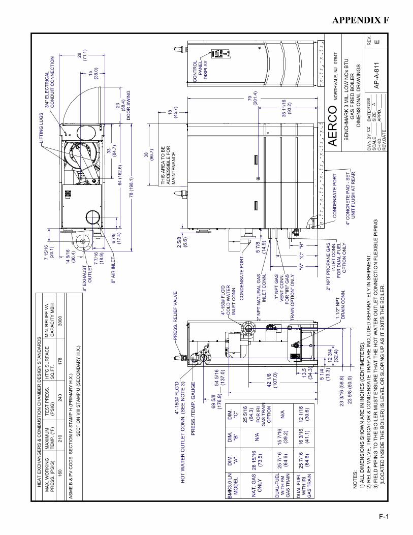
APPENDIX F
F-1
79
(201
.4)
36 1
1/16
(9
3.2)
15
(38.
0)
33
(84.
7)6
7/8
(17.
4)
7 7/
16
(18.
9)
42 1
/8
(107
.0)
69 5
/8
(176
.9)
5 1/
4 (1
3.3)
12 3
/4
(32.
4)
13.5
(3
4.3)
2 5/
8 (6
.6)
7 15
/16
(20.
1)
14 5
/16
(36.
4)
64 (1
62.6
)
1" N
PT
GA
SV
EN
T C
ON
N.
FOR
"IR
I" G
AS
TR
AIN
OP
TIO
N" O
NLY
2" N
PT
NA
TUR
AL
GA
SIN
LET
CO
NN
.
4"-1
50#
FLG
'DC
OLD
WA
TER
INLE
T C
ON
N.
1-1/
2" N
PT
DR
AIN
CO
NN
.4"
CO
NC
RE
TE P
AD
- S
ET
UN
IT F
LUS
H A
T R
EA
R
8" E
XH
AU
ST
OU
TLE
T
8" A
IR IN
LET
PR
ES
S. R
ELI
EF
VA
LVE
3/4"
ELE
CTR
ICA
L C
ON
DU
IT C
ON
NE
CTI
ON
54 5
/16
(137
.0)
"A"
5 7/
8 (1
4.9)
4"-1
50#
FLG
'DH
OT
WA
TER
OU
TLET
CO
NN
. (S
EE N
OTE
3)
23
(58.
4)D
OO
R S
WIN
G
CO
NTR
OL
PA
NE
L D
ISP
LAY
CO
ND
EN
SA
TE P
OR
T
CO
ND
EN
SA
TE P
OR
T
28
(71.
1)
HEA
T EX
CH
ANG
ERS
& C
OM
BUST
ION
CH
AMBE
R D
ESIG
N S
TAN
DAR
DS
TEST
PR
ESS.
ASM
E B
& PV
CO
DE:
SEC
TIO
N IV
STA
MP
H (P
RIM
ARY
H.X
.)
PRES
S. (P
SIG
)M
AX. W
OR
KIN
G
160
210
TEM
P. (°
F)24
0(P
SIG
)M
AXIM
UM
CAP
ACIT
Y M
BHM
IN. R
ELIE
F VA
.
178
SQ.F
T.30
00
HT'
G S
UR
FAC
E
NO
RTH
VALE
, NJ
076
47
DIM
ENSI
ON
AL D
RAW
ING
SG
AS F
IRED
BO
ILER
BEN
CH
MAR
K 3
MIL
. LO
W N
Ox
BTU
REV
.DAT
EC
HKD
.AP
PD.
CZ
DW
N.B
YSC
ALE
DAT
ESI
ZEA
0726
06
AER
CO
EAP
-A-8
11R
EV.
2) R
ELIE
F VA
LVE,
TR
IDIC
ATO
R &
CO
ND
ENSA
TE T
RAP
AR
E IN
CLU
DED
SEP
ARAT
ELY
IN S
HIP
MEN
T.1)
ALL
DIM
ENSI
ON
S SH
OW
N A
RE
IN IN
CH
ES (C
ENTI
MET
ERS)
.N
OTE
S:
SEC
TIO
N V
III S
TAM
P U
(SEC
ON
DAR
Y H
.X.)
LIFT
ING
LU
GS
PRE
SS./T
EM
P. G
AU
GE
18
(45.
7)
THIS
AR
EA
TO
BE
A
CC
ES
SIB
LE F
OR
M
AIN
TEN
AN
CE
.
38
(96.
7)
78 (1
98.1
)
"C"
"B"
2" N
PT
PR
OP
AN
E G
AS
INLE
T C
ON
N.
FOR
DU
AL-
FUE
LO
PTI
ON
ON
LY
NA
T. G
ASO
NLY
BM
K3.0
LN
MO
DEL
DU
AL-
FUE
LW
ITH
FM
GA
S T
RA
IN
DU
AL-
FUE
LW
ITH
IRI
GA
S T
RA
IN
25 7
/16
(64.
6)
25 7
/16
(64.
6)
28 1
5/16
(73.
5)
DIM
."A
"
FOR
IRI
GA
S T
RA
INO
PTI
ON
25 5
/16
(64.
3)
DIM
."C
"
12 1
/16
(30.
6)
N/A
16 3
/16
(41.
1)
15 7
/16
(39.
2)
DIM
."B
"
N/A
23 3
/16
(58.
8)23
5/8
(60.
0)
(LO
CAT
ED IN
SID
E TH
E BO
ILER
) IS
LEVE
L O
R S
LOPI
NG
UP
AS IT
EXI
TS T
HE
BOIL
ER.
3) F
IELD
PIP
ING
TO
TH
E BO
ILER
MU
ST E
NSU
RE
THAT
TH
E H
OT
WAT
ER O
UTL
ET C
ON
NEC
TIO
N F
LEXI
BLE
PIPI
NG

APPENDIX F
F-2
FRO
NT
RE
AR26
(6
6.0)
AERC
O 0615
06
0615
06
ANC
HO
R B
OLT
LO
CAT
ION
S
BEN
CH
MA
RK
3 M
IL. L
OW
NO
x BT
UG
AS F
IRED
BO
ILE
R
SC
ALE
DW
N.B
Y
APP
D.
GS
MC
DA
TE
DA
TES
D-A
-680
REV
.A
INTE
RN
ATIO
NAL
, IN
C.
NO
RTH
VA
LE, N
J 0
7647
23(5
8.4) 1
1/2
(3.8
)36
7/8
(93.
7)
62
(157
.5)
9(2
2.9)
AN
CH
OR
HO
LE 4
X Ø
.75
(Ø1.
91) T
HR
U H
OLE
S
4
PL
3) A
LL D
IME
NS
ION
S S
HO
WN
AR
E IN
INC
HE
S (C
EN
TIM
ETE
RS
)
1) D
OTT
ED
LIN
ES
RE
PR
ES
EN
T B
EN
CH
MA
RK
SH
EE
T M
ETA
L2)
ALL
HO
LES
AR
E F
LUS
H W
ITH
TH
E B
OTT
OM
SU
RFA
CE
OF
THE
FR
AM
E
NO
TES
:
64(1
62.6
)
28(7
1.1)

APPENDIX F
F-3
TOP
VIEW
SID
E VI
EW
INST
ALLA
TIO
N C
LEAR
ANC
ES
1) T
HIS
APP
LIAN
CE
MAY
BE
INST
ALLE
D O
N C
OM
BUST
IBLE
FLO
OR
ING
24"
24"
24"
79"
18"
101"
2) M
INIM
UM
CLE
ARAN
CES
TO
AD
JAC
ENT
CO
NST
RU
CTI
ON
AR
E AS
FO
LLO
WS:
LEFT
AN
D R
IGH
T SI
DES
: 24'
'FR
ON
T: 2
4"R
EAR
: 43"
(SEE
NO
TE)
CEI
LIN
G H
EIG
HT:
101
"
BEN
CH
MAR
K 3
MIL
. BTU
LO
W N
Ox
GAS
FIR
ED B
OIL
ER
4" H
IGH
PAD
ZER
O S
IDE
CLE
ARAN
CE
INST
ALLA
TIO
N
FRO
NT
56"
NO
RTH
VALE
, NJ
076
47IN
TER
NAT
ION
AL, I
NC
.
APPD
.
DW
N.B
YSC
ALE
DAT
EM
C
DAT
EG
S06
1506
AER
CO
SD-A
-683
CREV
.
REA
R
43"
78"
FO
R Z
ERO
SID
E C
LEAR
ANC
E IN
STAL
LATI
ON
S
TW
O U
NIT
SET
S4)
TH
E ZE
RO
SID
E C
LEAR
ANC
E O
PTIO
N C
AN O
NLY
BE
EMPL
OYE
D IN
3) T
HE
INN
ER S
IDE
PAN
ELS
MU
ST B
E R
EMO
VED
FR
OM
BO
TH U
NIT
S
W
HEN
USI
NG
A R
EAR
CLE
ARAN
CE
OF
LESS
TH
AN 4
3", A
57"
FR
ON
T C
LEAR
ANC
E
WIL
L BE
NEE
DED
TO
ALL
OW
TH
E R
EMO
VAL
OF
EXH
AUST
CO
NN
ECTI
NG
MAN
IFO
LD.
REA
R C
LEAR
ANC
E M
AY B
E R
EDU
CED
TO
24"
DEP
END
ENT
UPO
N P
IPIN
G A
ND
VEN
TIN
G
CO
MPO
NEN
T SE
LEC
T IO
N, A
RR
ANG
EMEN
T, A
ND
LO
CAL
CO
DE
REQ
UIR
EMEN
TS.
HO
WEV
ER,
NO
TE:
(SEE
NO
TE)

APPENDIX F
F-4
TOP
VIEW
SID
E VI
EW
INST
ALLA
TIO
N C
LEAR
ANC
ES
1) T
HIS
APP
LIAN
CE
MAY
BE
INST
ALLE
D O
N C
OM
BUST
IBLE
FLO
OR
ING
2) M
INIM
UM
CLE
ARAN
CES
TO
AD
JAC
ENT
CO
NST
RU
CTI
ON
AR
E AS
FO
LLO
WS:
LEFT
AN
D R
IGH
T SI
DES
: 24'
'FR
ON
T: 2
4"R
EAR
: 43"
(SEE
NO
TE)
CEI
LIN
G H
EIG
HT:
101
"
BEN
CH
MAR
K 3
MIL
. BTU
LO
W N
Ox
GAS
FIR
ED B
OIL
ERIN
STAL
LATI
ON
CLE
ARAN
CES
28"
C
OM
PON
ENT
SELE
CTI
ON
, AR
RAN
GEM
ENT,
AN
D L
OC
AL C
OD
E R
EQU
IREM
ENTS
. H
OW
EVER
, R
EAR
CLE
ARAN
CE
MAY
BE
RED
UC
ED T
O 2
4" D
EPEN
DEN
T U
PON
PIP
ING
AN
D V
ENTI
NG
NO
TE:
NO
RTH
VALE
, NJ
076
47IN
TER
NAT
ION
AL, I
NC
.
APPD
.
DW
N.B
YSC
ALE
DAT
EM
C
DAT
EG
S06
1506
AER
CO
SD-A
-686
BREV
.
REA
RFR
ON
T
24"
43"
24"
24"
101"
4" H
IGH
PAD
79"
78"
18"
W
HEN
USI
NG
A R
EAR
CLE
ARAN
CE
OF
LESS
TH
AN 4
3", A
57"
FR
ON
T C
LEAR
ANC
E
WIL
L BE
NEE
DED
TO
ALL
OW
TH
E R
EMO
VAL
OF
EXH
AUST
CO
NN
ECTI
NG
MAN
IFO
LD.(S
EE N
OTE
)

APPENDIX F
F-5

APPENDIX F
F-6
DU
AL F
UEL
IRI G
AS T
RAI
N
JK07
1307
APPD
.C
HKD
.
DW
N.B
YSI
ZESC
ALE
DAT
ER
EV.
NO
RTH
VALE
, NJ
076
47IN
TER
NAT
ION
AL, I
NC
.AE
RC
O
NTS
C
BEN
CH
MAR
K 3.
0 LO
W N
Ox
LOW
GAS
PR
ESS.
SW
ITC
HP/
N: 6
1002
-1
2"-S
CH
.40
PIPE
1"-S
CH
.40
PIPE
2"-S
CH
.40
PIPE
BOIL
ER B
OU
ND
ARY
VEN
T TO
ATM
OSP
HER
EPE
R A
NSI
Z22
3.1
(NFP
A54)
ENTI
RE
ASSE
MBL
Y PA
RT
NU
MBE
R
AP-A
-826
HIG
H G
AS P
RES
S.
SWIT
CH
(PR
OPA
NE)
P/N
: 610
02-1
6
1/8"
NPT
PLU
G(IN
STAL
L M
ANO
MET
ER H
ERE)
TEST
C
OC
KH
IGH
GAS
PR
ESS.
SW
ITC
H
(NAT
UR
AL G
AS)
P/N
: 610
02-1
5
1" N
OR
MAL
LY O
PEN
VEN
T VA
LVE
P/N
123
769
SAFE
TY S
HU
T-O
FFVA
LVE
ACTU
ATO
RP/
N 6
9038
SAFE
TY S
HU
T-O
FFVA
LVE
ACTU
ATO
R w
/ R
EGU
LATO
RP/
N 6
4048
TO A
IR-F
UEL
VAL
VE A
SS'Y
FULL
PO
RT
BALL
VAL
VE2"
NPT
P/N
: 123
540
2" D
OU
BLE
BOD
YC
ON
NEC
TIN
G F
LAN
GE
P/N
: 124
156
2" S
AFET
Y SH
UT-
OFF
DO
UBL
E-BO
DY
GAS
VAL
VEP/
N 1
2414
2
2204
0-2
NAT
UR
AL G
AS
PRO
PAN
E
NAT
UR
AL G
AS
PRO
PAN
E
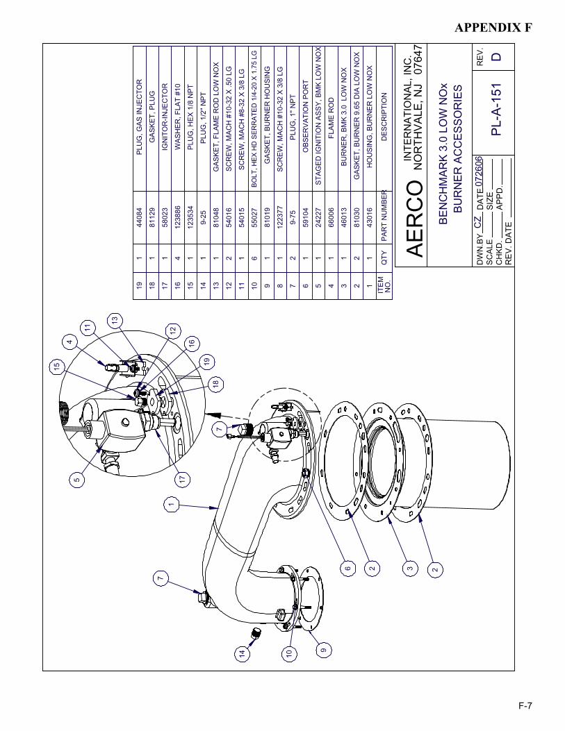
APPENDIX F
F-7
BEN
CH
MAR
K 3.
0 LO
W N
Ox
BUR
NER
AC
CES
SOR
IES
CZ
0726
06
PL-A
-151
DD
ATE
APPD
.SI
ZEC
HKD
.
DW
N.B
YSC
ALE
REV
.
AER
CO
NO
RTH
VALE
, NJ
076
47IN
TER
NAT
ION
AL, I
NC
.
REV
. DAT
E
191
4408
4PL
UG
, GAS
INJE
CTO
R
181
8112
9G
ASKE
T, P
LUG
171
5802
3IG
NIT
OR
-INJE
CTO
R
164
1238
86W
ASH
ER, F
LAT
#10
151
1235
34PL
UG
, HEX
1/8
NPT
141
9-25
PLU
G, 1
/2" N
PT
131
8104
8G
ASKE
T, F
LAM
E R
OD
LO
W N
OX
122
5401
6SC
REW
, MAC
H #
10-3
2 X
.50
LG
111
5401
5SC
REW
, MAC
H #
8-32
X 3
/8 L
G
106
5502
7BO
LT, H
EX H
D S
ERR
ATED
1/4
-20
X 1.
75 L
G
91
8101
9G
ASKE
T, B
UR
NER
HO
USI
NG
81
1223
77SC
REW
, MAC
H #
10-3
2 X
3/8
LG
72
9-75
PLU
G, 1
" NPT
61
5910
4O
BSER
VATI
ON
PO
RT
51
242 2
7ST
AGED
IGN
ITIO
N A
SSY,
BM
K LO
W N
OX
41
6600
6FL
AME
RO
D
31
4601
3BU
RN
ER, B
MK
3.0
LO
W N
OX
22
8103
0G
ASKE
T, B
UR
NER
9.6
5 D
IA L
OW
NO
X
11
4301
6H
OU
SIN
G, B
UR
NER
LO
W N
OX
ITEM
N
O.
QTY
PAR
T N
UM
BER
DES
CR
IPTI
ON
6
1
2 3
9
1014
7
2
7
54
11
13
16
1918
1712
15
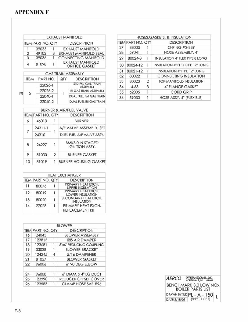
APPENDIX F
F-8
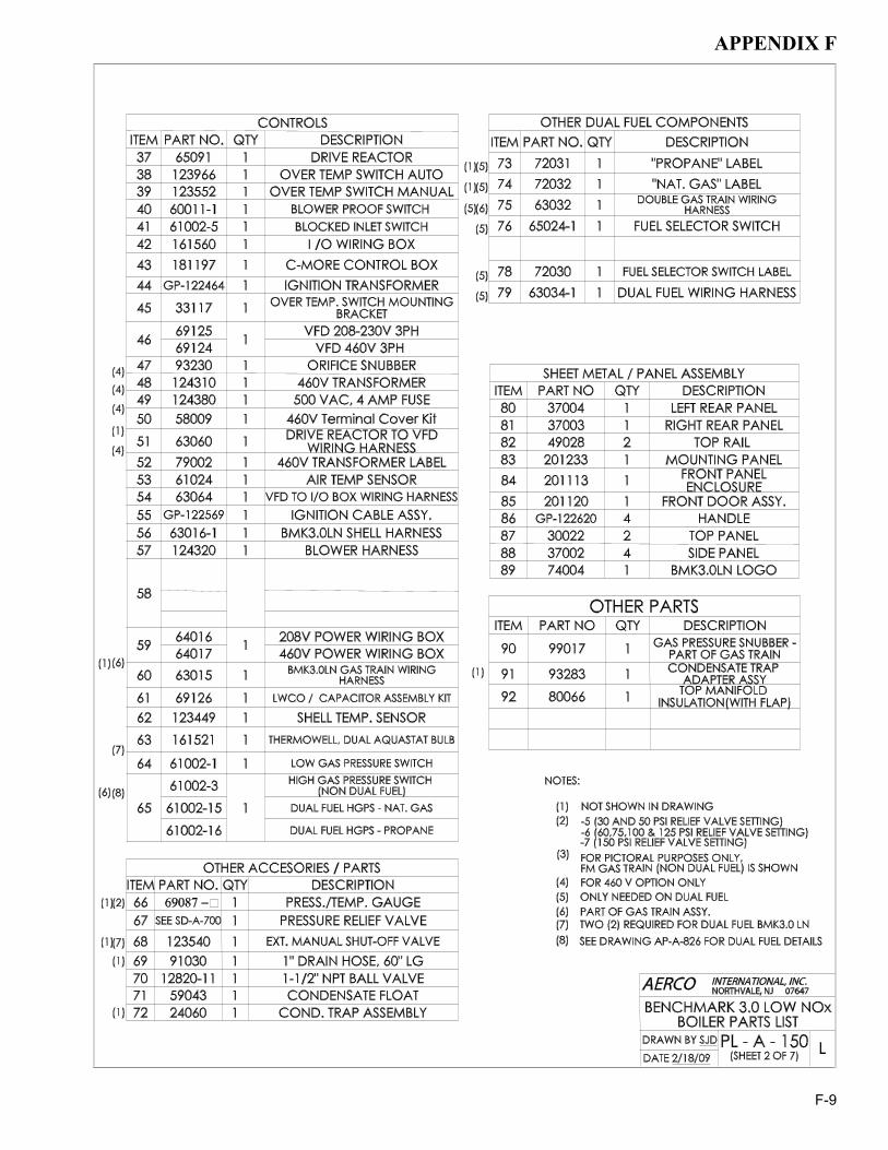
APPENDIX F
F-9

APPENDIX F
F-10
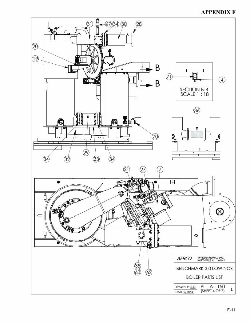
APPENDIX F
F-11

APPENDIX F
F-12

APPENDIX F
F-13
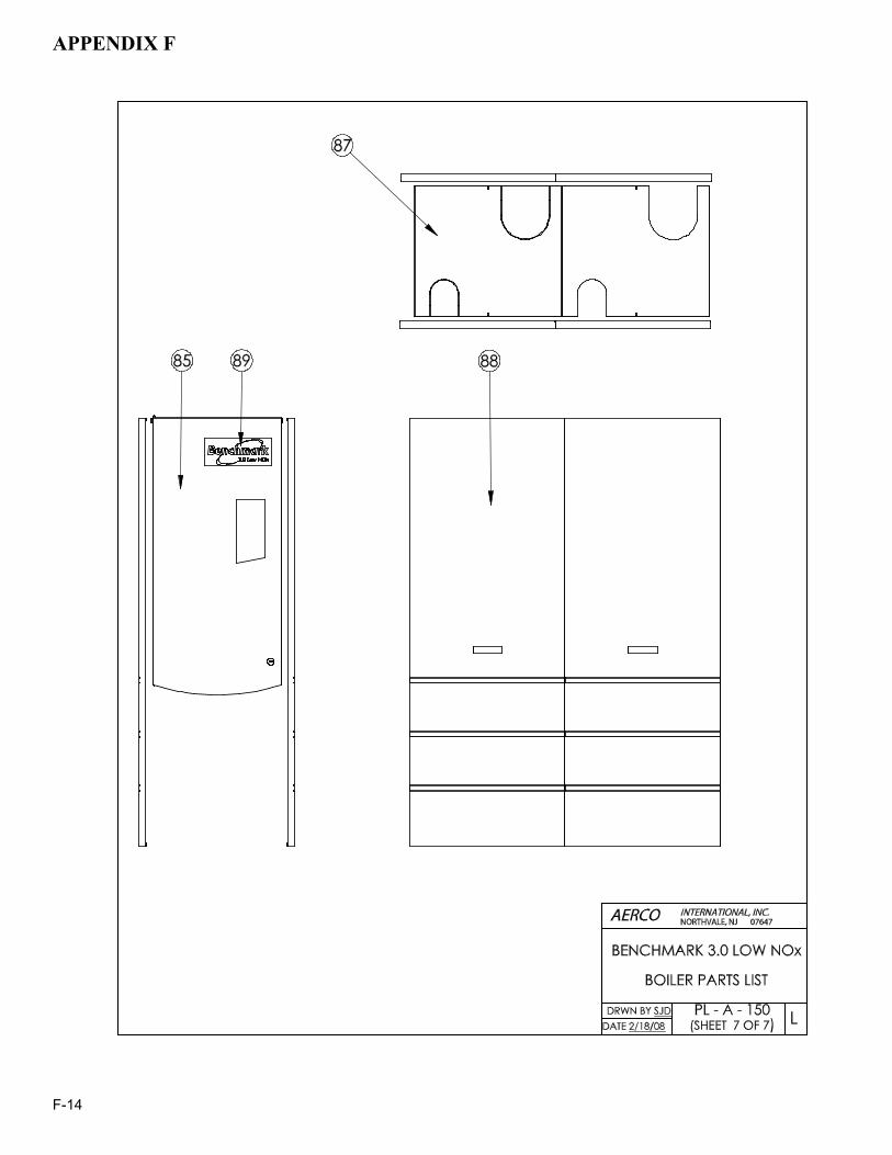
APPENDIX F
F-14

APPENDIX G
G-1
AIR
SEP
ARA
TOR
AU
TOM
ATI
CA
IR V
EN
T
LIN
ES
IZE
BYP
ASS
BAC
KFL
OW
PR
EV
ENTE
R
DIA
PH
RA
GM
TY
PE
EXP
ANS
ION
TA
NK
WA
TER
SU
PPLY PR
ESS
UR
ER
EDU
CIN
GFI
LL V
ALV
E
CH
ECK
VA
LVE
(TY
P.)
HEA
TIN
GS
YSTE
M
SU
PP
LY
SY
STEM
PU
MP
P&T
RE
LIEF
VALV
E (T
YP.)
HEA
TIN
GS
YST
EM
RE
TUR
N
AT
MA
XIM
UM
BTU
/HR
INP
UT,
M
AIN
TAIN
MIN
IMU
M G
AS P
RES
SU
RE
AT
6.5"
W.C
. M
AX G
AS
PRE
SSU
RE
= 2
.0 P
SIG
. (S
EE
NO
TE 6
)
* 2"
MA
NU
AL
SH
UTO
FFV
ALVE
GA
S SU
PPL
Y
TEM
PE
RA
TUR
E G
AU
GE
P&
TP
RES
SU
RE
&BA
LAN
CIN
G V
ALV
E
ISO
LATI
ON
VAL
VE
UN
ION
Y ST
RAI
NE
RLE
GE
ND
AERC
O
JK CZ
BE
NC
HM
AR
K 3
MIL
. BTU
LO
W N
Ox
SIN
GLE
UN
IT IN
STA
LLA
TIO
N
SCAL
ED
WN
.BY
APP
D.
SD
-A-7
23
INTE
RN
ATIO
NA
L, IN
C.
NO
RTH
VALE
, NJ
076
47
0702
07D
ATE
DA
TE
DU
AL
FUEL
GA
S FI
RE
D B
OIL
ER
RE
V.C
DR
IP T
RA
P* C
ON
DE
NS
ATE
DR
AIN
TR
AP
1-1/
2" N
PTD
RAI
N C
ON
N.
NA
TUR
AL
SUP
PLY
PRO
PAN
E
AT
MA
XIM
UM
BTU
/HR
INPU
T,
MAI
NTA
IN M
INIM
UM
PR
OP
ANE
PR
ES
SUR
E A
T 4.
0" W
.C.
MAX
PR
OP
AN
E P
RES
SUR
E =
2.0
PSIG
. (S
EE N
OTE
6)
(SE
E N
OTE
7)
DO
WN
STR
EAM
OF
THE
2" M
ANU
AL S
HU
TOFF
VA
LVE
TO
BR
ING
TH
E G
AS P
RES
SU
RE
DO
WN
TO
2.0
PS
IG.
6) W
HE
N A
VAI
LAB
LE G
AS P
RES
SU
RE
IS G
RE
ATE
R T
HA
N 2
.0 P
SIG
, A L
OC
K-U
P ST
YLE
RE
GU
LATO
R M
US
T BE
INS
TALL
ED
FITT
ING
S T
O P
RE
VEN
T IN
TER
FER
EN
CE
WIT
H R
EM
OV
AL
OF
BO
ILE
R P
AN
ELS
AN
D C
OVE
RS
. A
LL P
IPIN
G A
ND
FR
EE
LY, B
Y G
RA
VIT
Y, T
O A
CO
NV
ENIE
NT
FLO
OR
DR
AIN
. R
ELI
EF V
ALV
E SH
OU
LD B
E P
IPE
D V
ER
TIC
ALL
Y TO
A
1) F
OR
AC
TUA
L S
IZES
AN
D L
OC
ATI
ON
S O
F P
IPIN
G A
ND
OTH
ER C
ON
NEC
TIO
NS
TO
TH
E B
OIL
ER
, SEE
DIM
EN
SIO
NA
L D
RA
WIN
G (A
P-A-
802)
.
ELE
CTR
IC C
ON
NE
CTI
ON
S (S
ER
VIC
E S
WIT
CH
ES, C
ON
DU
IT B
OX
ES)
SH
OU
LD L
IKEW
ISE
4) L
OC
ATE
WA
TER
INLE
T A
ND
OU
TLET
FIT
TIN
GS
(i.e.
UN
ION
S, E
LBO
WS
, ETC
.) A
MIN
IMU
M O
F 6'
' FR
OM
BO
ILE
R
2) S
HEL
L D
RA
IN V
ALV
E A
ND
CO
ND
EN
SATE
DR
AIN
TR
AP S
HO
ULD
BE
AR
RA
NG
ED
TO
PER
MIT
TH
E F
LUID
S TO
DR
AIN
5) T
HIS
IS A
TY
PIC
AL IN
STA
LLA
TIO
N D
RA
WIN
G.
L OC
AL
CO
DE
S A
ND
AU
THO
RIT
IES
SH
OU
LD B
E C
ON
SU
LTED
.B
E 6
'' AW
AY
FRO
M S
IDE
PAN
ELS
.
3) A
LL (*
) ITE
MS
AR
E IN
CLU
DED
SEP
AR
ATE
LY IN
SH
IPM
ENT
FRO
M F
AC
TOR
Y.
HEI
GH
T 18
'' ABO
VE
FLO
OR
.
NO
TES
:
7) E
AC
H C
ON
DE
NS
ATE
PO
RT
CAN
BE
PIP
ED
IND
IVID
UA
LLY
TO
MA
IN D
RA
IN.
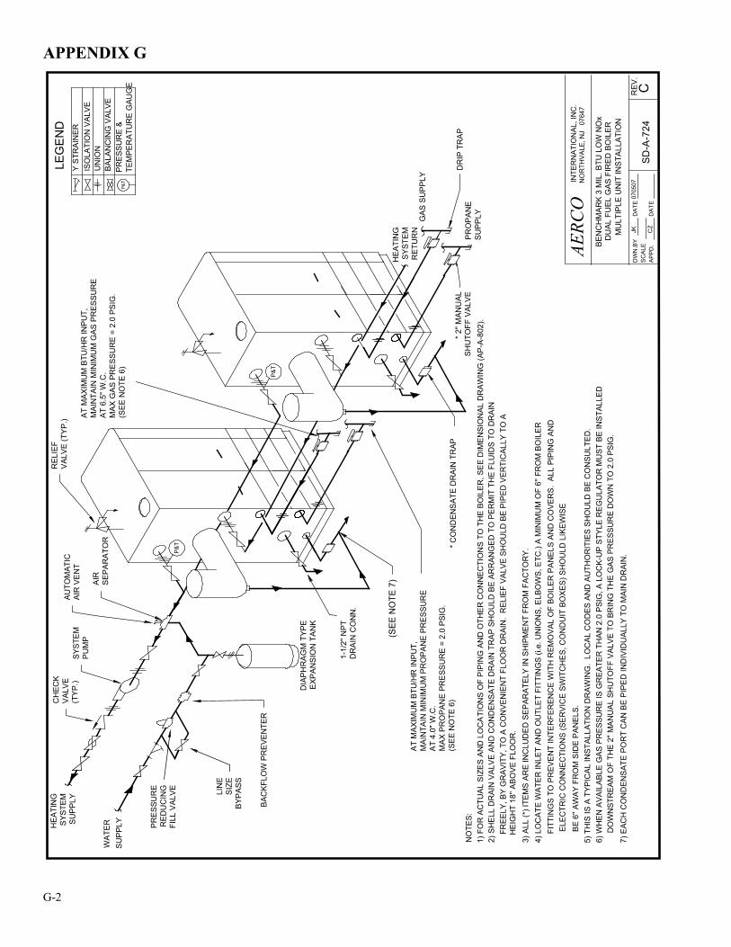
APPENDIX G
G-2
NO
RTH
VALE
, NJ
076
47IN
TER
NA
TIO
NA
L, IN
C.
APPD
.
DW
N.B
YS
CA
LED
ATE
CZ
DAT
EJK
0705
07
AERC
O
SD-A
-724
CREV
.
BEN
CH
MA
RK
3 M
IL. B
TU L
OW
NO
xD
UAL
FU
EL G
AS F
IRED
BO
ILER
MU
LTIP
LE U
NIT
INS
TALL
ATI
ON
P&T
AUTO
MAT
ICAI
R V
EN
T
AIR
SEP
AR
ATO
R
1-1/
2" N
PTD
RA
IN C
ON
N.
* CO
ND
EN
SA
TE D
RA
IN T
RA
P
PR
ES
SUR
ER
ED
UC
ING
FILL
VA
LVE
DIA
PH
RA
GM
TY
PE
EXP
AN
SIO
N T
AN
K
BAC
KFL
OW
PR
EVE
NTE
R
LIN
ES
IZE
BYP
ASS
HE
ATI
NG
SYS
TEM
S
UP
PLY
SUP
PLY
WA
TER
SYS
TEM
PU
MP
CH
ECK
VA
LVE
(TY
P.)
AT
MA
XIM
UM
BTU
/HR
INP
UT,
M
AIN
TAIN
MIN
IMU
M G
AS P
RES
SU
RE
AT
6.5"
W.C
.M
AX G
AS
PRE
SSU
RE
= 2
.0 P
SIG
. (S
EE
NO
TE 6
)
HEA
TIN
GS
YST
EM
R
ETU
RN
* 2"
MA
NU
AL
SH
UTO
FF V
ALV
E
REL
IEF
VAL
VE
(TY
P.)
ISO
LATI
ON
VA
LVE
BA
LAN
CIN
G V
ALV
E
TEM
PER
ATU
RE
GAU
GE
LEG
EN
DY
STR
AIN
ER
UN
ION
PRE
SSU
RE
&P&
T
DR
IP T
RA
P
GA
S S
UP
PLY
P&T
(SEE
NO
TE 7
)
PR
OP
AN
ES
UP
PLY
AT
MAX
IMU
M B
TU/H
R IN
PU
T,
MA
INTA
IN M
INIM
UM
PR
OP
AN
E P
RES
SU
RE
AT
4.0"
W.C
.M
AX
PRO
PAN
E PR
ESS
UR
E =
2.0
PSI
G.
(SE
E N
OTE
6)
DO
WN
STR
EA
M O
F TH
E 2"
MA
NU
AL
SHU
TOFF
VA
LVE
TO
BR
ING
TH
E G
AS
PR
ES
SUR
E D
OW
N T
O 2
.0 P
SIG
.6)
WH
EN
AVA
ILAB
LE G
AS
PR
ES
SUR
E IS
GR
EAT
ER T
HAN
2.0
PSI
G, A
LO
CK-
UP
STY
LE R
EG
ULA
TOR
MU
ST
BE
INS
TALL
ED
FITT
ING
S TO
PR
EVE
NT
INTE
RFE
REN
CE
WIT
H R
EMO
VAL
OF
BOIL
ER P
AN
ELS
AN
D C
OV
ERS
. AL
L PI
PIN
G A
ND
FR
EELY
, BY
GR
AVIT
Y, T
O A
CO
NVE
NIE
NT
FLO
OR
DR
AIN
. R
ELIE
F VA
LVE
SH
OU
LD B
E P
IPED
VER
TIC
ALLY
TO
A
1) F
OR
AC
TUA
L S
IZE
S A
ND
LO
CA
TIO
NS
OF
PIP
ING
AN
D O
THE
R C
ON
NE
CTI
ON
S T
O T
HE
BOIL
ER, S
EE
DIM
EN
SIO
NA
L D
RA
WIN
G (A
P-A
-802
).
ELE
CTR
IC C
ON
NEC
TIO
NS
(SE
RV
ICE
SWIT
CH
ES
, CO
ND
UIT
BO
XES
) SH
OU
LD L
IKE
WIS
E
4) L
OC
ATE
WA
TER
INLE
T AN
D O
UTL
ET
FITT
ING
S (i
.e. U
NIO
NS
, ELB
OW
S, E
TC.)
A M
INIM
UM
OF
6'' F
RO
M B
OIL
ER
2) S
HE
LL D
RAI
N V
ALV
E A
ND
CO
ND
ENS
ATE
DR
AIN
TR
AP
SH
OU
LD B
E AR
RAN
GED
TO
PE
RM
IT T
HE
FLU
IDS
TO
DR
AIN
5) T
HIS
IS A
TY
PIC
AL
INST
ALLA
TIO
N D
RA
WIN
G.
L OC
AL
CO
DES
AN
D A
UTH
OR
ITIE
S S
HO
ULD
BE
CO
NSU
LTE
D.
BE
6'' A
WA
Y F
RO
M S
IDE
PA
NE
LS.
3) A
LL (*
) ITE
MS
AR
E IN
CLU
DE
D S
EP
ARA
TELY
IN S
HIP
ME
NT
FRO
M F
AC
TOR
Y.
H
EIG
HT
18'' A
BO
VE F
LOO
R.
NO
TES:
7) E
ACH
CO
ND
ENS
ATE
POR
T C
AN
BE
PIP
ED
IND
IVID
UAL
LY T
O M
AIN
DR
AIN
.

APPENDIX G
G-3
NO
RTH
VALE
, NJ
076
47IN
TER
NA
TIO
NA
L, IN
C.
APPD
.
DW
N.B
YS
CAL
ED
ATE
DAT
EJK
0702
07
AERC
O
SD
-A-7
25CRE
V.
BEN
CH
MA
RK
3 M
IL. B
TU L
OW
NO
xD
UAL
FU
EL G
AS F
IRED
BO
ILER
MU
LTIP
LE IN
STA
LLA
TIO
N
P&T
AUTO
MA
TIC
AIR
VE
NT
AIR
SEP
ARA
TOR
1-1/
2" N
PTD
RA
IN C
ON
N.
PRES
SUR
ER
EDU
CIN
GFI
LL V
ALV
E DIA
PHR
AGM
TYP
EEX
PAN
SIO
N T
ANK
BAC
KFLO
W P
RE
VEN
TER
LIN
ES
IZE
BYPA
SS
HE
ATIN
GSY
STE
M
SUPP
LY
SU
PPL
YW
ATER
SYS
TEM
PUM
P
CH
ECK
VAL
VE(T
YP.)
AT
MA
XIM
UM
BTU
/HR
INP
UT,
M
AIN
TAIN
MIN
IMU
M G
AS P
RES
SUR
EA
T 6.
5" W
.C.
MA
X G
AS
PRES
SUR
E =
2.0
PSIG
. (S
EE N
OTE
6)
* 2" M
ANU
ALSH
UTO
FF V
ALV
E
REL
IEF
VALV
E (T
YP.)
ISO
LATI
ON
VA
LVE
BA
LAN
CIN
G V
ALV
E
TEM
PER
ATU
RE
GAU
GE
LEG
EN
DY
STR
AIN
ER
UN
ION
PRE
SSU
RE
&P&
T
DR
IP T
RAP
(SE
E N
OTE
7)
*CO
ND
ENS
ATE
D
RAI
N T
RA
P
HEA
TIN
GSY
STE
M
RET
UR
N
P&T
GA
S SU
PPL
Y
P&T
(2 Z
ERO
-SID
E &
1 S
EPA
RA
TE)
CZ
NAT
UR
AL
SUP
PLY
PRO
PAN
E
AT
MA
XIM
UM
BTU
/HR
INP
UT,
M
AIN
TAIN
MIN
IMU
M P
RO
PAN
E P
RES
SUR
EA
T 4.
0" W
.C.
MA
X PR
OPA
NE
PR
ESSU
RE
= 2.
0 PS
IG.
(SE
E N
OTE
6)
DO
WN
STR
EAM
OF
THE
2" M
AN
UA
L S
HU
TOFF
VAL
VE T
O B
RIN
G T
HE
GA
S PR
ESS
UR
E D
OW
N T
O 2
.0 P
SIG
.6)
WH
EN
AV
AIL
AB
LE G
AS
PRES
SU
RE
IS G
REA
TER
TH
AN
2.0
PS
IG, A
LO
CK
-UP
STY
LE R
EGU
LATO
R M
UST
BE
INST
ALLE
D
FITT
ING
S T
O P
RE
VEN
T IN
TER
FER
EN
CE
WIT
H R
EM
OVA
L O
F B
OIL
ER
PAN
ELS
AN
D C
OVE
RS.
ALL
PIP
ING
AN
D
FR
EE
LY, B
Y G
RA
VIT
Y, T
O A
CO
NV
EN
IEN
T FL
OO
R D
RA
IN.
RE
LIE
F V
ALV
E S
HO
ULD
BE
PIP
ED
VE
RTI
CA
LLY
TO
A
1) F
OR
AC
TUA
L SI
ZES
AND
LO
CA
TIO
NS
OF
PIP
ING
AN
D O
THER
CO
NN
EC
TIO
NS
TO T
HE
BO
ILE
R, S
EE D
IME
NS
ION
AL D
RA
WIN
G (A
P-A-
802)
.
ELE
CTR
IC C
ON
NE
CTI
ON
S (S
ER
VIC
E S
WIT
CH
ES,
CO
ND
UIT
BO
XES
) SH
OU
LD L
IKEW
ISE
4) L
OC
ATE
WA
TER
INLE
T A
ND
OU
TLE
T FI
TTIN
GS
(i.e
. UN
ION
S, E
LBO
WS
, ETC
.) A
MIN
IMU
M O
F 6'
' FR
OM
BO
ILER
2) S
HEL
L D
RA
IN V
ALV
E A
ND
CO
ND
EN
SATE
DR
AIN
TR
AP
SH
OU
LD B
E A
RR
AN
GE
D T
O P
ER
MIT
TH
E F
LUID
S T
O D
RAI
N
5) T
HIS
IS A
TYP
ICAL
INS
TALL
ATI
ON
DR
AWIN
G.
LOC
AL C
OD
ES
AND
AU
THO
RIT
IES
SH
OU
LD B
E C
ON
SU
LTED
.B
E 6
'' AW
AY
FRO
M S
IDE
PAN
ELS
.
3) A
LL (*
) ITE
MS
AR
E IN
CLU
DED
SE
PAR
ATEL
Y IN
SH
IPM
EN
T FR
OM
FAC
TOR
Y.
H
EIG
HT
18'' A
BOV
E FL
OO
R.
NO
TES
:
7) E
AC
H C
ON
DE
NSA
TE P
OR
T C
AN
BE
PIP
ED IN
DIV
IDU
ALL
Y T
O M
AIN
DR
AIN
.

APPENDIX G
G-4
NO
RTH
VALE
, NJ
076
47IN
TER
NA
TIO
NA
L, IN
C.
APP
D.
DW
N.B
YSC
ALE
DA
TE
DA
TEJK
0702
07
AERC
O
SD
-A-7
26CRE
V.
BE
NC
HM
AR
K 3
MIL
. BTU
LO
W N
Ox
DU
AL F
UE
L G
AS
FIR
ED
BO
ILE
R M
ULT
.IN
STA
LLA
TIO
N W
ITH
ZE
RO
SID
E C
LEA
RA
NC
E
P&T
AU
TOM
ATIC
AIR
VE
NT
AIR
SEP
AR
ATO
R
1-1/
2" N
PTD
RAI
N C
ON
N.
PRES
SUR
ER
EDU
CIN
GFI
LL V
ALVE
DIA
PHR
AG
M T
YPE
EXP
AN
SIO
N T
ANK
BAC
KFL
OW
PR
EVEN
TER
LIN
ES
IZE
BYP
ASS
HEA
TIN
GSY
STEM
SU
PPLY
SUPP
LYW
ATER
SYS
TEM
PU
MP
CH
ECK
VALV
E(T
YP.)
AT
MAX
IMU
M B
TU/H
R IN
PUT,
M
AIN
TAIN
MIN
IMU
M G
AS
PR
ESSU
RE
AT 6
.5" W
.C.
MA
X G
AS P
RES
SUR
E =
2.0
PSIG
. (S
EE
NO
TE 6
)
* 2" M
AN
UAL
SHU
TOFF
VA
LVE
REL
IEF
VALV
E (T
YP.)
ISO
LATI
ON
VAL
VE
BALA
NC
ING
VA
LVE
TEM
PE
RA
TUR
E G
AU
GE
LEG
EN
DY
STR
AIN
ER
UN
ION
PR
ESS
UR
E &
P&T
DR
IP T
RA
P
* CO
ND
ENS
ATE
DR
AIN
TR
AP
HE
ATIN
GS
YSTE
M
RET
UR
N
P&T
NAT
UR
ALG
AS
SU
PPL
Y
P&T
P&T
CZ
SUPP
LYPR
OPA
NE
AT M
AXIM
UM
BTU
/HR
INPU
T,
MAI
NTA
IN M
INIM
UM
PR
OPA
NE
PR
ESS
UR
E A
T 4.
0" W
.C.
MAX
PR
OP
ANE
PR
ESSU
RE
= 2.
0 P
SIG
. (S
EE N
OTE
6)
(SEE
NO
TE 7
)
DO
WN
STR
EA
M O
F TH
E 2
" MA
NU
AL
SHU
TOFF
VAL
VE
TO B
RIN
G T
HE
GA
S P
RE
SSU
RE
DO
WN
TO
2.0
PS
IG.
6) W
HE
N A
VAIL
ABLE
GA
S PR
ESS
UR
E IS
GR
EATE
R T
HA
N 2
.0 P
SIG
, A L
OC
K-U
P S
TYLE
RE
GU
LATO
R M
UST
BE
INST
ALL
ED
FITT
ING
S TO
PR
EV
ENT
INTE
RFE
RE
NC
E W
ITH
REM
OVA
L O
F B
OIL
ER P
ANE
LS A
ND
CO
VER
S.
ALL
PIP
ING
AN
D
FR
EELY
, BY
GR
AVIT
Y, T
O A
CO
NV
EN
IEN
T FL
OO
R D
RAI
N.
REL
IEF
VALV
E S
HO
ULD
BE
PIP
ED
VER
TIC
ALL
Y T
O A
1) F
OR
AC
TUA
L SI
ZES
AN
D L
OC
ATI
ON
S O
F P
IPIN
G A
ND
OTH
ER
CO
NN
EC
TIO
NS
TO T
HE
BO
ILER
, SE
E D
IME
NSI
ON
AL
DR
AWIN
G (A
P-A
-802
).
ELE
CTR
IC C
ON
NE
CTI
ON
S (S
ERV
ICE
SWIT
CH
ES,
CO
ND
UIT
BO
XES
) SH
OU
LD L
IKE
WIS
E
4) L
OC
ATE
WAT
ER
INLE
T A
ND
OU
TLE
T FI
TTIN
GS
(i.e
. UN
ION
S, E
LBO
WS,
ETC
.) A
MIN
IMU
M O
F 6'
' FR
OM
BO
ILE
R
2) S
HE
LL D
RA
IN V
ALV
E AN
D C
ON
DEN
SAT
E D
RA
IN T
RA
P SH
OU
LD B
E A
RR
AN
GE
D T
O P
ER
MIT
TH
E FL
UID
S T
O D
RA
IN
5) T
HIS
IS A
TYP
ICA
L IN
STA
LLA
TIO
N D
RA
WIN
G.
LOC
AL C
OD
ES
AN
D A
UTH
OR
ITIE
S SH
OU
LD B
E C
ON
SULT
ED
.BE
6'' A
WA
Y F
RO
M S
IDE
PA
NE
LS.
3) A
LL (*
) ITE
MS
AR
E IN
CLU
DE
D S
EPA
RAT
ELY
IN S
HIP
ME
NT
FRO
M F
ACTO
RY
.
HE
IGH
T 18
'' AB
OV
E F
LOO
R.
NO
TES:
7) E
ACH
CO
ND
EN
SATE
PO
RT
CA
N B
E P
IPED
IND
IVID
UA
LLY
TO
MA
IN D
RAI
N.

APPENDIX H
H-1
T1 T2 T4T3 T6T5B2 B4 B5
JUMPER # 368JUMPER # 367
SOLENOID
6 PIN CONNECTOR
195194193192
191190
208209
202203
206
204
201
AUTO RESET
OVER TEMPERATURE SWITCHESMANUAL RESET
137 209 136
190138135136193141
BLO
WER
PR
OO
F SW
.
142
154
WAT
ER L
EVEL
PR
OBE
IGN
ITO
R
351
321
FLAM
E R
OD G
ND
352
137191 194 155 154
TRANSFORMERIGNITION
141
192 140 195
19-PIN CONNECTOR13161719 18 15 14 12 1110 9 8 7 6 5 4 3 2 1 16 15
152 150 148 146 134133162166168172 170
C
N
148
3STEPPING
AIR/FUEL VALVE
SWIT
CH
POSI
TIO
NIG
NIT
ION
SWIT
CH
POSI
TIO
NPU
RG
E
C53
MOTOR 5K B
A
BLK
WH
T YEL
BLU
GR
N
RED
2 10K
1
CLO
SUR
E SW
ITC
HPR
OO
F O
F
GAS
PR
ESS.
SW
.
GAS
PR
ESS.
SW
.
407 150
H
152 405
NC1K
401
167173 171 169 163165 161 153 151 149
403146147
G
SHELL
SENSORTEMP.
147 145
4
9-PIN CONNECTORCONTROL BOX CONNECTORS
16-PIN CONNECTOR1314 12 11 10 9 8 7 6 5 4 3 2 1
164
789 56 123 7 6 5 4 3 2 1
7-PIN CONNECTOR
PRO
OF
OF
CLO
SUR
E SW
ITC
H
SSO
V
N
CNC
H
1K
G
401
SSO
V
402
402400
145
403404
404
3 PO
SITI
ON
FU
ELSE
LEC
TOR
SW
ITC
H
405
PRO
PAN
E H
IGH
GAS
PR
ESS.
SW
.
151
405
151
405
405
153
408407
GAS
PR
ESS.
SW
.
408
152
NAT
. GAS
LO
WPR
OPA
NE
LOW
408
NAT
. GAS
HIG
H
408407
BLO
CKE
D A
IR IN
LET
SW.
XFMR24 VAC
FUSE
FUSE
L3L2
L1
200
POWER BOX
208 VAC60 HZ
L1
L2
L3
331
333
332
260
263262
261260 GND BLOCK
TO CONTROL BOX {
321320
206
261
262
263203
330
200
350
366
209207
208
201
202
204
142
ENCLOSURE
GND
NEUFUSE BLOCK
20 AMP
20 AMP
20 AMPMOTOR
BLOWER331
333
332
L3
L2
L1 U
W
V
303
302
301
300PEPE
VFD
A1 B1A2 B2 C1 C2
DRIVEREACTOR
GND375330
331
333
332
375
SENSORTEMP.AIR
364363 TO I/O BOX
AIR TEMPSENSOR
3O
WIRING SCHEMATIC BMK 3.0 DF208 VAC, 3 PHASE
REF: 68012 REV. G (SHT. 1 OF 2)
+ + + + + + + +1 2 3 4 5 6 7 8+ + + + + + + +9 10 11 12 13 14 15 16
TO I/O BOX104103
375331332333
300301302303
JUMPER # 367JUMPER # 368
U1/LV1/NW1PE
U2V2W2
NET A (0-10V)NET B (A. GND.)
ALTERNATE SCHEMATIC FOR ABB VFD
(FOR ABB VFD, SEE ALTERNATE SCHEMATIC) EMERSON VFD
TO I/O BOX
NET A (0-10V)NET B (AGND)103
104
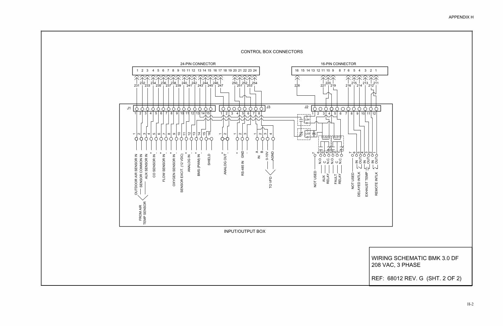
APPENDIX H
H-2
CONTROL BOX CONNECTORS
1210 11 13 14 1615 17 18 19 2120 22 23 24
24-PIN CONNECTOR
241240 242
243244
245 251246 250
247252 254
253
9 68 7 5 4 3 12
220221 219
16-PIN CONNECTOR
854 6 7 91 2 3 1116 1415 13 12 10
226213
214216215
7 6 7 5 346 12
OU
TINO
UT
ININ OU
TD
ELAY
ED IN
TLK
EXH
AUST
TEM
P
REM
OTE
INTL
K
N.O
.C
4 35 12
NO
T U
SED
N.C
.CN.O
.N
.C.
REL
AYAU
X
12 13 1411SE
NSO
R E
XCIT
. (12
VD
C)
BMS
(PW
M) I
N
ANAL
OG
IN
OXY
GEN
SEN
SOR
IN
FLO
W S
ENSO
R IN
CO
SEN
SOR
IN
+ - -+-+-+
AUX
SEN
SOR
INSE
NSO
R C
OM
MO
N IN
-+
1O
UTD
OO
R A
IR S
ENSO
R IN
98753 42 6 10
INGN
D
41 21
-+
2 21 33
ANAL
OG
OU
T
15 16SH
IELD
B
RS-
485
IN
A
1 2 43 7 865 9 10 12118765432187654321 1211109 13 14 15
231234232
233238236
235 237 239
INPUT/OUTPUT BOX
+ -
LS2 LS1
LS4
LS3
J3 J2J1
212211
0-10
VAG
ND
FRO
M A
IRTE
MP
SEN
SOR
TO V
FD
FAU
LTR
ELAY
NO
T U
SED
WIRING SCHEMATIC BMK 3.0 DF208 VAC, 3 PHASE
REF: 68012 REV. G (SHT. 2 OF 2)
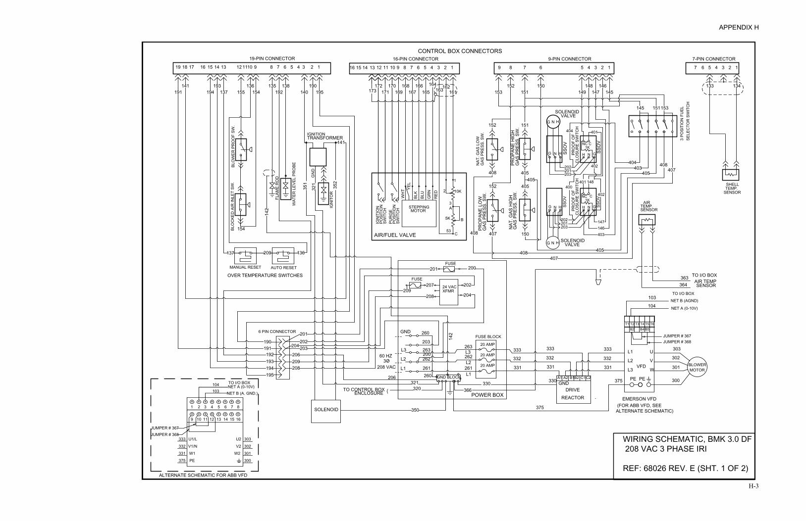
APPENDIX H
H-3
ENCLOSURETO CONTROL BOX
SOLENOID
6 PIN CONNECTOR
195194193192
191190
208209
202203
206
204
201
AUTO RESET
OVER TEMPERATURE SWITCHES
MANUAL RESET
137 209 136
350
330
POWER BOX
262L2
206
{ 320321
L1 261260
366
GND BLOCK
142
261L1
L2
L360 HZ
208 VAC
263200
203
GND 260
L3262
263
332
331
333
208
207209 XFMR
24 VAC
204
202
201
FUSE
FUSE200
190138135136193141
BLO
WER
PR
OO
F SW
.
142
154
WAT
ER L
EVEL
PR
OBE
IGN
ITO
R
351
321
FLAM
E R
OD G
ND
352
137191 194 155 154
TRANSFORMERIGNITION
141
192 140 195
19-PIN CONNECTOR
13161719 18 15 14 12 1110 9 8 7 6 5 4 3 2 1 16 15
152 150 148 146 134133162166168172 170
C
N
148
3STEPPING
AIR/FUEL VALVE
SWIT
CH
POSI
TIO
NIG
NIT
ION
SWIT
CH
POSI
TIO
NPU
RG
E
C53
MOTOR
5K B
A
BLK
WH
T YEL
BLU
GR
NR
ED
2 10K
1
CLO
SUR
E SW
ITC
HPR
OO
F O
F
GAS
PR
ESS.
SW
.
GAS
PR
ESS.
SW
.
SSO
V
407 150
201203
G N H
202
H
152 405
NC1K
401
167173 171 169 163165 161 153 151 149
403146147
G
SHELL
SENSORTEMP.
147 145
4
9-PIN CONNECTORCONTROL BOX CONNECTORS
16-PIN CONNECTOR
1314 12 11 10 9 8 7 6 5 4 3 2 1
164
789 56 123 7 6 5 4 3 2 1
7-PIN CONNECTOR
203
202201
SSO
VPR
OO
F O
F
HNG
CLO
SUR
E SW
ITC
H
SSO
V
N
CNC
H
1KG
401
SSO
V
402
402
400
145
403404
404
3 PO
SITI
ON
FU
ELSE
LEC
TOR
SW
ITC
H
405
PRO
PAN
E H
IGH
G
AS P
RES
S. S
W. 151
405
151
405
405
153
408407
GAS
PR
ESS.
SW
.
408
152
NAT
. GAS
LO
WPR
OPA
NE
LOW
408
NAT
. GAS
HIG
H
408407
BLO
CKE
D A
IR IN
LET
SW.
SOLENOID
NGVALVE
H
SOLENOIDNG VALVEH
FUSE BLOCK
20 AMP
20 AMP
20 AMPMOTORBLOWER331
333
332
L3
L2
L1 U
W
V
303
302
301
300PEPE
VFD
A1 B1A2 B2 C1C2
DRIVEREACTOR
GND 375330
331
333
332
375
SENSORTEMP.
AIR
364363 TO I/O BOX
AIR TEMPSENSOR
3O
T1 T2 T4T3 T6T5
TO I/O BOX
NET A (0-10V)
NET B (AGND)
B2 B4 B5
JUMPER # 368JUMPER # 367
+ + + + + + + +1 2 3 4 5 6 7 8
+ + + + + + + +9 10 11 12 13 14 15 16
TO I/O BOX104103
375
331
332
333
300
301
302
303
JUMPER # 367JUMPER # 368
U1/L
V1/N
W1
PE
U2
V2
W2
NET A (0-10V)NET B (A. GND.)
ALTERNATE SCHEMATIC FOR ABB VFD
(FOR ABB VFD, SEE ALTERNATE SCHEMATIC)
EMERSON VFD
WIRING SCHEMATIC, BMK 3.0 DF 208 VAC 3 PHASE IRI
REF: 68026 REV. E (SHT. 1 OF 2)
103
104
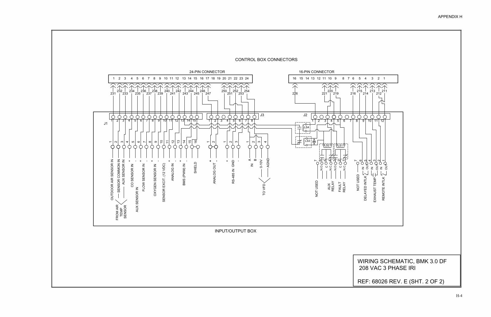
APPENDIX H
H-4
CONTROL BOX CONNECTORS
1210 11 13 14 1615 17 18 19 2120 22 23 24
24-PIN CONNECTOR
241240 242
243244
245 251246 250
247252 254
253
9 68 7 5 4 3 12
212220
221211
219
16-PIN CONNECTOR
854 6 7 91 2 3 1116 1415 13 12 10
226213
214216215
7 6 7 5 346 12
OU
T
INOU
T
ININ OU
T
FAU
LTR
ELAY
NO
T U
SED
DEL
AYED
INTL
K
EXH
AUST
TEM
P
REM
OTE
INTL
K
N.O
.
C4 35 12
NO
T U
SED
N.C
.C
N.O
.N
.C.
REL
AYAU
X
12 13 1411SE
NSO
R E
XCIT
. (12
VD
C)
BMS
(PW
M) I
N
ANAL
OG
IN
OXY
GEN
SEN
SOR
IN
FLO
W S
ENSO
R IN
CO
SEN
SOR
IN
+ - -+-+-+
AUX
SEN
SOR
INSE
NSO
R C
OM
MO
N IN -+
1O
UTD
OO
R A
IR S
ENSO
R IN
98753 42 6 10
INGN
D
41 21
-+
2 21 3315 16SH
IELD
B
RS-
485
IN
A
1 2 43 7 865 9 10 12118765432187654321 1211109 13 14 15
231234232
233238236
235 237 239
INPUT/OUTPUT BOX
+ -
LS2 LS1
LS4
LS3
J3 J2
J1
ANAL
OG
OU
T+ -
AUX
SEN
SOR
IN
0-10
V
AGN
D
FRO
M A
IRTE
MP
SEN
SOR
TO V
FDWIRING SCHEMATIC, BMK 3.0 DF 208 VAC 3 PHASE IRI
REF: 68026 REV. E (SHT. 2 OF 2)

APPENDIX H
H-5
123456789123456789101112131415 123456789101112
CONTROL BOX CONNECTORS
BLO
WER
PR
OO
F SW
.
OVER TEMPERATURE SWITCHES
IGN
ITO
R
TRANSFORMER
WAT
ER L
EVEL
PR
OBE
FLAM
E R
OD
16-PIN CONNECTOR19-PIN CONNECTOR
MANUAL RESET
STEPPINGMOTOR
PUR
GE
POSI
TIO
N
IGN
ITIO
NPO
SITI
ON
SWIT
CH
SWIT
CH
AIR/FUEL VALVE
BLKYE
LW
HT
53
5K
C
B
A3
REDGR
NBL
U 2 10K
1
1819 17 16 141516 13
154
AUTO RESET
IGNITION
XFORMER24 VAC
206
FUSE
FUSE
191
141
136137 209
L3
L2
L1
GND
200203
314315
POWER BOX
460VAC
60 HZ
330
L1
L2
L3
331
333
332
CONTROL TRANSFORMER
H2316H1
317
H4
460VAC
H3
X2 X14 AMPSXFFUSE
120 VAC
260
263
262
261
260 GND BLOCK
GN
D32
1
TO CONTROL BOX {321320
319
206
261
262
263316
319330
317
141194 137
193155 154
136 135192
138140 195
190171
170172169
168167
166165
164163
162161
SOLENOID
351
350
352
6 PIN CONNECTOR
366
201202
204 203
209208
190191192193194195
209207
208
201 200
202
204
315314
142
142
173
ENCLOSURE
G
CLO
SUR
E SW
ITC
HPR
OO
F O
F
SSO
V
NAT
. GAS
LO
WG
AS P
RES
S. S
W.
PRO
PAN
E H
IGH
GAS
PR
ESS.
SW
.
408
PRO
PAN
E LO
W
GAS
PR
ESS.
SW
.
407 150
407408
405 403
148
CLO
SUR
E SW
ITC
HPR
OO
F O
F
GAS
PR
ESS.
SW
.N
AT. G
AS H
IGH
NH
CNC1K
405408
152 405405 401
400
H N
147146
SSO
V
G
402
405402
404403 407
408
SENSORTEMP.SHELL
7
7-PIN CONNECTOR
148
152 151
CNC1K
404
150152153 151 149
SELE
CTO
R S
WIT
CH
3 PO
SITI
ON
FU
EL
401
145
146147 145
151 153
9 8 7
9-PIN CONNECTOR
5 4 23 1
133 134
56 4 23 1
BLO
CKE
D A
IR IN
LET
SW.
FUSE BLOCK
15 AMP
15 AMP
15 AMP MOTORBLOWER
331
333
332
L3
L2
L1 U
W
V
303
302
301
300PEPE
VFD
A1 B1A2 B2 C1 C2
DRIVEREACTOR
GND 375330
331
333
332
375
SENSORTEMP.
AIR
364363 TO I/O BOX
AIR TEMPSENSOR
3O
WIRING SCHEMATIC, BMK 3.0 DF460 VAC 3 PHASE
REF: 68013 REV. G (SHT. 1 OF 2)
+ + + + + + + +1 2 3 4 5 6 7 8
+ + + + + + + +9 10 11 12 13 14 15 16
TO I/O BOX104
103
375
331
332
333
300
301
302
303
JUMPER # 367
JUMPER # 368U1/L
V1/N
W1
PE
U2
V2
W2
NET A (0-10V)
NET B (A. GND.)
ALTERNATE SCHEMATIC FOR ABB VFD
(FOR ABB VFD, SEE ALTERNATE SCHEMATIC)
EMERSON VFD
T1 T2 T4T3 T6T5
TO I/O BOX
NET A (0-10V)NET B (AGND)
B2 B4 B5
JUMPER # 368JUMPER # 367
103104
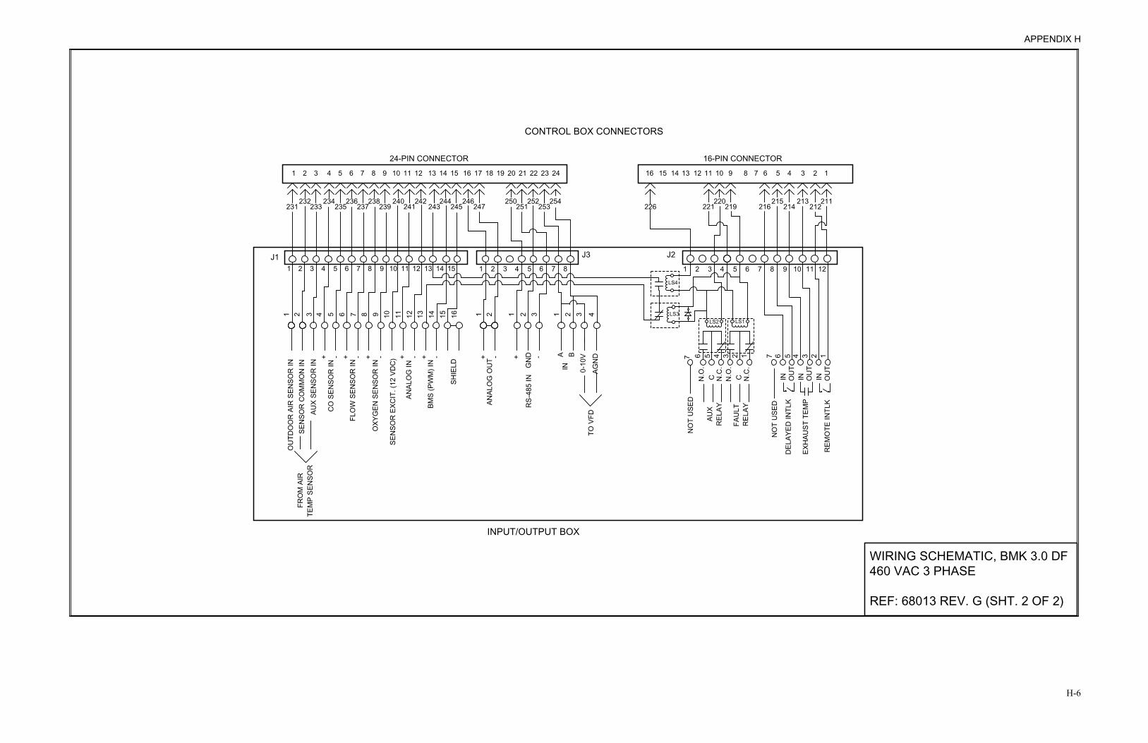
APPENDIX H
H-6
CONTROL BOX CONNECTORS
1210 11 13 14 1615 17 18 19 2120 22 23 24
24-PIN CONNECTOR
241240 242
243244
245 251246 250
247252 254
253
9 68 7 5 4 3 12
220221 219
16-PIN CONNECTOR
854 6 7 91 2 3 1116 1415 13 12 10
226213
214216215
7 6 7 5 346 12
OU
TINO
UT
ININ OU
TD
ELAY
ED IN
TLK
EXH
AUST
TEM
P
REM
OTE
INTL
K
N.O
.C
4 35 12
NO
T U
SED
N.C
.CN.O
.N
.C.
REL
AYAU
X
12 13 1411SE
NSO
R E
XCIT
. (12
VD
C)
BMS
(PW
M) I
N
ANAL
OG
IN
OXY
GEN
SEN
SOR
IN
FLO
W S
ENSO
R IN
CO
SEN
SOR
IN
+ - -+-+-+
AUX
SEN
SOR
INSE
NSO
R C
OM
MO
N IN
-+
1O
UTD
OO
R A
IR S
ENSO
R IN
98753 42 6 10
INGN
D
41 21
-+
2 21 33
ANAL
OG
OU
T
15 16SH
IELD
B
RS-
485
IN
A
1 2 43 7 865 9 10 12118765432187654321 1211109 13 14 15
231234232
233238236
235 237 239
INPUT/OUTPUT BOX
+ -
LS2 LS1
LS4
LS3
J3 J2J1
212211
0-10
VAG
ND
FRO
M A
IRTE
MP
SEN
SOR
TO V
FD
FAU
LTR
ELAY
NO
T U
SED
WIRING SCHEMATIC, BMK 3.0 DF460 VAC 3 PHASE
REF: 68013 REV. G (SHT. 2 OF 2)

APPENDIX H
H-7
123456789123456789101112131415 123456789101112
CONTROL BOX CONNECTORS
BLO
WER
PR
OO
F SW
.
OVER TEMPERATURE SWITCHES
IGN
ITO
R
TRANSFORMER
WAT
ER L
EVEL
PR
OBE
FLAM
E R
OD
16-PIN CONNECTOR19-PIN CONNECTOR
MANUAL RESET
STEPPINGMOTOR
PUR
GE
POSI
TIO
N
IGN
ITIO
NPO
SITI
ON
SWIT
CH
SWIT
CH
AIR/FUEL VALVE
BLK
YEL
WH
T
53
5K
C
B
A3
RED
GR
N
BLU 2 10K
1
1819 17 16 141516 13
154
AUTO RESET
IGNITION
XFMR24 VAC
206
FUSE
FUSE
191
141
136137 209
L3
L2
L1
GND
200203 314
315
POWER BOX
460VAC
60 HZ
330
L1
L2
L3
331
333
332
CONTROL TRANSFORMER
H2
316
H1317
H4
460VAC
H3
X2X1
4 AMPS
XF
FUSE
120 VAC
260
263
262
261260 GND BLOCK
GN
D32
1
TO CONTROL BOX {
321320
319
206
261
262
263316
319330
317
141194 137
193155 154
136 135192
138140 195
190171
170172169
168167
166165
164163
162161
SOLENOID
351
350
352
6 PIN CONNECTOR
366
201202
204 203
209208
190191192193194195
209207
208
201 200
202
204
315314
142
142
173
ENCLOSURE
G
SSO
V
G
CLO
SUR
E SW
ITC
HPR
OO
F O
F
SSO
V
NAT
. GAS
LO
WG
AS P
RES
S. S
W.
PRO
PAN
E H
IGH
G
AS P
RES
S. S
W.
408
PRO
PAN
E LO
W
GAS
PR
ESS.
SW
.
407 150
407408
405
403
148
CLO
SUR
E SW
ITC
HPR
OO
F O
F
GAS
PR
ESS.
SW
.N
AT. G
AS H
IGH
202203201
SSO
V
G N H NH
CNC1K
405408
152 405405 401
400
203
HN
201202
H N
147146
SSO
V
G
402
405402
404403 407
408
SENSORTEMP.SHELL
7
7-PIN CONNECTOR
148
152 151
CNC1K
404
150152153 151 149
SELE
CTO
R S
WIT
CH
3 PO
SITI
ON
FU
EL
401
145
146147 145
151 153
9 8 7
9-PIN CONNECTOR6 5 4 23 1
133 134
56 4 23 1
BLO
CKE
D A
IR IN
LET
SW.
SOLENOID
NGVALVE
H
SOLENOIDNG VALVEH
FUSE BLOCK
15 AMP
15 AMP
15 AMPMOTOR
BLOWER331
333
332
L3
L2
L1 U
W
V
303
302
301
300PEPE
VFD
A1 B1A2 B2 C1 C2
DRIVEREACTOR
GND 375330
331
333
332
375
SENSORTEMP.
AIR
364363 TO I/O BOX
AIR TEMPSENSOR
3O
WIRING SCHEMATIC, BMK 3.0 DF 460 VAC 3 PHASE IRI
REF: 68027 REV. E (SHT. 1 OF 2)
T1 T2 T4T3 T6T5
TO I/O BOX
NET A (0-10V)NET B (AGND)
B2 B4 B5
JUMPER # 368JUMPER # 367
+ + + + + + + +1 2 3 4 5 6 7 8
+ + + + + + + +9 10 11 12 13 14 15 16
TO I/O BOX104
103
375
331
332
333
300
301
302
303
JUMPER # 367
JUMPER # 368U1/L
V1/N
W1
PE
U2
V2
W2
NET A (0-10V)
NET B (A. GND.)
ALTERNATE SCHEMATIC FOR ABB VFD
(FOR ABB VFD, SEE ALTERNATE SCHEMATIC)
EMERSON VFD
103
104

APPENDIX H
H-8
CONTROL BOX CONNECTORS
1210 11 13 14 1615 17 18 19 2120 22 23 24
24-PIN CONNECTOR
241240 242
243244
245 251246 250
247252 254
253
9 68 7 5 4 3 12
212220
221211
219
16-PIN CONNECTOR
854 6 7 91 2 3 1116 1415 13 12 10
226213
214216215
7 6 7 5 346 12
OU
T
INOU
T
ININ OU
T
FAU
LTR
ELAY
NO
T U
SED
DEL
AYED
INTL
K
EXH
AUST
TEM
P
REM
OTE
INTL
K
N.O
.
C4 35 12
NO
T U
SED
N.C
.C
N.O
.N
.C.
REL
AYAU
X
12 13 1411SE
NSO
R E
XCIT
. (12
VD
C)
BMS
(PW
M) I
N
ANAL
OG
IN
OXY
GEN
SEN
SOR
IN
FLO
W S
ENSO
R IN
CO
SEN
SOR
IN
+ - -+-+-+
AUX
SEN
SOR
INSE
NSO
R C
OM
MO
N IN -+
1O
UTD
OO
R A
IR S
ENSO
R IN
98753 42 6 10
INGN
D
41 21
-+
2 21 3315 16SH
IELD
B
RS-
485
IN
A
1 2 43 7 865 9 10 12118765432187654321 1211109 13 14 15
231234232
233238236
235 237 239
INPUT/OUTPUT BOX
+ -
LS2 LS1
LS4
LS3
J3 J2
J1
ANAL
OG
OU
T+ -
AUX
SEN
SOR
IN
0-10
V
AGN
D
FRO
M A
IRTE
MP
SEN
SOR
TO V
FD
WIRING SCHEMATIC, BMK 3.0 DF 460 VAC 3 PHASE IRI
REF: 68027 REV. E (SHT. 2 OF 2)

APPENDIX I
I-1
RECOMMENDED PERIODIC TESTING CHECK LIST
WARNING NOTE: Periodic testing of all boiler controls and safety devices is required to determine that they are operating as designed. Precautions shall be taken while tests are being performed to protect against bodily injury and property damage. The owner or user of an automatic boiler system should set up a formal system of periodic preventive maintenance and testing. Tests should be conducted on a regular basis and the results recorded in a log-book.
Item
Frequency
Accomplished By
Remarks
Refer to indicated paragraphs of this manual for detailed procedures Gauges, monitors and indicators Daily Operator Visual inspection and record readings in operator
log Instrument and equipment settings Daily Operator Visual check against factory recommended
specifications Weekly Operator Verify factory settings
Firing Rate Control Semi-Annually
Service Technician Verify factory settings
Annually Service Technician
Check with combustion calibration test equipment. See paragraph 7.4 and Chapter 4.
Flue, vent, stack or intake air duct Monthly Operator Visually inspection condition and check for
obstructions Ignitor-Injector Weekly Operator See paragraph 7.2 Air/Fuel Valve position Weekly Operator Check position indicator dial (paragraph 3.9)
SSOV Leakage test Annually Service Technician
Check for leakage in accordance with the SSOV manufacturer’s (Siemens) recommendations.
Flame failure Weekly Operator Close manual gas shutoff valve and check safety shutdown. See paragraph 6.9
Flame signal strength Weekly Operator Check flame strength using the Control Panel Operating Menu. See paragraph 3.4.
Low water level cut off and alarm Weekly Operator See paragraph 6.6
Slow drain test Semi-Annually Operator
Perform a slow drain test in accordance with ASME Boiler and Pressure Vessel Code, Section IV.
High water temperature safety control test Annually Service
Technician See paragraph 6.7
Operating controls Annually Operator See paragraph 3.2 Low air flow Monthly Operator See paragraph 6.10 High and low gas pressure interlocks Monthly Operator See paragraphs 6.2 through 6.5
Air/Fuel Valve purge position switch Annually Service
Technician See paragraph 6.12
Air/Fuel Valve ignition position switch Annually Service
Technician See paragraph 6.13
Safety valves As required Operator Check per A.S.M.E. Boiler and Pressure Vessel Code, Section IV
Inspect burner components
Semi-Annually
Service Technician
See paragraph 7.6


APPENDIX J
J-1
VERTICAL OVERLAY, BENCHMARKP/N 124718
FRONT FACE PLATE, BENCHMARKP/N 124949
FISH PAPER INSULATORP/N 124960
ENCLOSUREP/N 124951
V.F.D. DISPLAYMODULE
P/N 124527
DISPLAY BOARDP/N 124365
PMC BOARDP/N 124364
LOW WATER CUTOFF BOARD P/N 124363
CONNECTOR BOARDP/N 124366
IGNITION/STEPPER BOARDP/N 124361
POWER SUPPLY BOARDP/N 124362
GREEN LEDP/N 124948
ROCKERSWITCH
P/N 124947
PUSH BUTTONSWITCHESP/N 124954
BENCHMARK CONTROL PANEL EXPLODED VIEW

APPENDIX J
J-2
P1P2
P3P4
P5P6
SHELL HARNESS CONNECTOR
(19 PIN)
GAS TRAIN HARNESS CONNECTOR
(9 PIN)
A/F VALVE HARNESS CONNECTOR
(16 PIN)
SENSOR HARNESS
CONNECTOR(7 PIN)
INTERLOCK HARNESS CONNECTOR
(16 PIN)TO INPUT/OUTPUT (I/O)
BOX
EXT. SENSOR/COMM HARNESS CONNECTOR
(24 PIN) TO INPUT/OUTPUT (I/O)
BOX
BENCHMARK CONTROL PANEL REAR VIEW

APPENDIX K
K-1
BENCHMARK 3.0 DUAL-FUEL
SWITCHOVER INSTRUCTIONS
Prior to operating a Benchmark 3.0 Dual-Fuel Unit on either Natural Gas or Propane, a number of checks and procedural steps must be performed prior to performing the initial start-up and combustion calibration, including adjusting the Max Fire Rate setting in the Configuration Menu of the C-More Control Box. Detailed instructions for performing these tasks are presented in the following sections. SWITCHOVER FROM NATURAL GAS TO PROPANE To switch from Natural Gas to Propane operation, proceed as follows:
1. Refer to Figure K-1 and locate the Fuel Selector Switch on the front of the unit.
2. Set the Fuel Selector Switch to the PROPANE position. A Low Gas pressure Fault message will be displayed on the Control Box.
3. Clear the Low Gas Pressure Fault by pressing the CLEAR key.
4. Set the ON/OFF switch on the C-More /control Box to the ON position.
5. Press the MENU key once. Setup Menu will be displayed.
6. Press the ▲ arrow key once. Password will be displayed.
7. Press the CHANGE key. Password will begin to flash.
8. Using the ▲ arrow key, increment the display and stop at 159.
9. Press the ENTER key to store the displayed password.
10. Password 1 will be displayed, indicating that the valid Level 1 password has been stored.
11. Next, access the Configuration Menu by pressing the MENU key once.
12. Using the ▲ and ▼ arrow keys, scroll through the Configuration Menu and stop at Max Valve Position.
13. Press the CHANGE key. The Max Valve Position will begin to flash.
14. Press the ▼ arrow key and decrease the Max Valve Position to 75%.
15. Press the ENTER key to store the 75% Max Valve Position.
16. Using the ▲ and ▼ arrow keys, scroll through the Configuration Menu and stop at Fuel Type.
17. Press the CHANGE key. Fuel Type will begin to flash.
18. Press the ▲ arrow key. Propane will be displayed.
19. Press the ENTER key to store the Propane Fuel type.
20. This completes the steps necessary to switch from Natural Gas to Propane operation.

APPENDIX K
K-2
POWER BOX
CONTROLPANEL
I/O BOX
TRANSFORMER(460 VAC UNITS ONLY)
FUELSELECTOR
SWITCH
FIGURE K-1. BENCHMARK 3.0 DUAL FRONT VIEW – DOOR REMOVED

APPENDIX K
K-3
SWITCHOVER FROM PROPANE TO NATURAL GAS To switch from Propane to Natural Gas operation, proceed as follows:
1. Refer to Figure K-1 and locate the Fuel Selector Switch on the front of the unit.
2. Set the Fuel Selector Switch to the NATURAL GAS position. A Low Gas pressure Fault message will be displayed on the Control Box.
3. Clear the Low Gas Pressure Fault by pressing the CLEAR key..
4. Apply AC power to the Benchmark 3.0 Dual Fuel Boiler.
5. Press the MENU key once. Setup Menu will be displayed.
6. Press the ▲ arrow key once. Password will be displayed.
7. Press the CHANGE key. Password will begin to flash.
8. Using the ▲ arrow key, increment the display and stop at 159.
9. Press the ENTER key to store the displayed password.
10. Password 1 will be displayed, indicating that the valid Level 1 password has been stored.
11. Next, access the Configuration Menu by pressing the MENU key once.
12. Using the ▲ and ▼ arrow keys, scroll through the Configuration Menu and stop at Max Valve Position.
13. Press the CHANGE key. The Max Valve Position will begin to flash.
14. Press the ▲ arrow key and increase the Max Valve Position to 100%.
15. Press the ENTER key to store the 100% Max Valve Position.
16. Using the ▲ and ▼ arrow keys, scroll through the Configuration Menu and stop at Fuel Type.
17. Press the CHANGE key. Fuel Type will begin to flash.
18. Press the ▼ arrow key. Natural Gas will be displayed.
19. Press the ENTER key to store the Natural Gas Fuel type.
20. This completes the steps necessary to switch from Propane to Natural Gas operation.

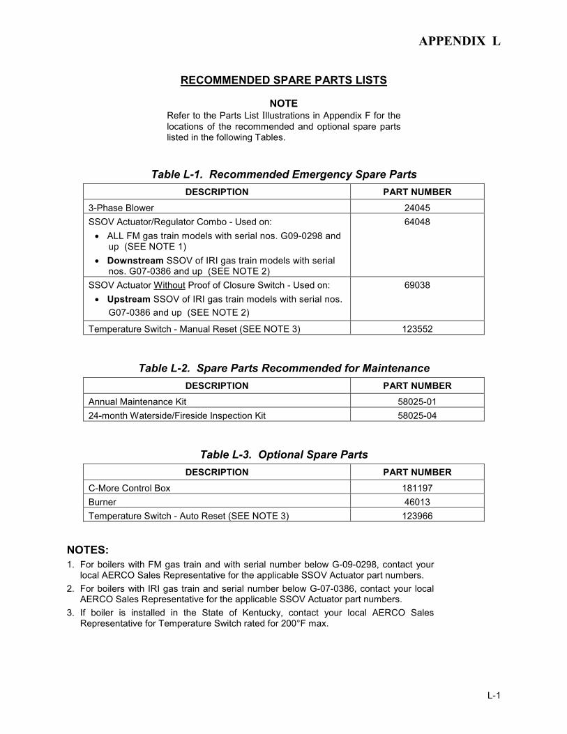
APPENDIX L
L-1
RECOMMENDED SPARE PARTS LISTS
NOTE Refer to the Parts List Illustrations in Appendix F for the locations of the recommended and optional spare parts listed in the following Tables.
Table L-1. Recommended Emergency Spare Parts DESCRIPTION PART NUMBER
3-Phase Blower 24045 SSOV Actuator/Regulator Combo - Used on: • ALL FM gas train models with serial nos. G09-0298 and
up (SEE NOTE 1) • Downstream SSOV of IRI gas train models with serial
nos. G07-0386 and up (SEE NOTE 2)
64048
SSOV Actuator Without Proof of Closure Switch - Used on: • Upstream SSOV of IRI gas train models with serial nos.
G07-0386 and up (SEE NOTE 2)
69038
Temperature Switch - Manual Reset (SEE NOTE 3) 123552
Table L-2. Spare Parts Recommended for Maintenance DESCRIPTION PART NUMBER
Annual Maintenance Kit 58025-01 24-month Waterside/Fireside Inspection Kit 58025-04
Table L-3. Optional Spare Parts DESCRIPTION PART NUMBER
C-More Control Box 181197 Burner 46013 Temperature Switch - Auto Reset (SEE NOTE 3) 123966
NOTES: 1. For boilers with FM gas train and with serial number below G-09-0298, contact your
local AERCO Sales Representative for the applicable SSOV Actuator part numbers. 2. For boilers with IRI gas train and serial number below G-07-0386, contact your local
AERCO Sales Representative for the applicable SSOV Actuator part numbers. 3. If boiler is installed in the State of Kentucky, contact your local AERCO Sales
Representative for Temperature Switch rated for 200°F max.