Bench Top Drill Press - Free Instruction Manuals · 1 Original Instruction Manual DP16B Bench Top...
20
Original Instruction Manual DP16B Bench Top Drill Press Important For your safety read instructions carefully before assembling or using this product. Save this manual for future reference. Always wear safety glasses when using woodworking equipment. Always read the instructions provided before using woodworking equipment. i Version 3.0 August 2014 To register this product please visit www.recordpower.info It is important to register your product as soon as possible in order to receive efficient after sales support and be entitled to the full 5 year guarantee. Your statutory rights are not affected. Please see back cover for contact details.
-
Upload
nguyenphuc -
Category
Documents
-
view
241 -
download
0
Transcript of Bench Top Drill Press - Free Instruction Manuals · 1 Original Instruction Manual DP16B Bench Top...

1
Original Instruction Manual
DP16B Bench Top Drill Press
ImportantFor your safety read instructions carefully before assembling or using this product.Save this manual for future reference.
Always wear safety glasses when using woodworking equipment.
Always read the instructions provided before using woodworking equipment.
i
Kg
Version 3.0August 2014
To register this product please visit
www.recordpower.infoIt is important to register your product as soon as possible in order to receive efficient after sales
support and be entitled to the full 5 year guarantee. Your statutory rights are not affected. Please see back cover for contact details.

2
Contents1. Explanation of Symbols
2. General Health & Safety Guidance
3. Record Power Guarantee
4. Specifications
5. Unpacking & Checking Contents
6. Getting to Know Your Machine
7 Assembly
8. Maintenance
9. Wiring Diagram
10. Troubleshooting
11. Parts Lists & Diagrams
Certificate of Conformity
3
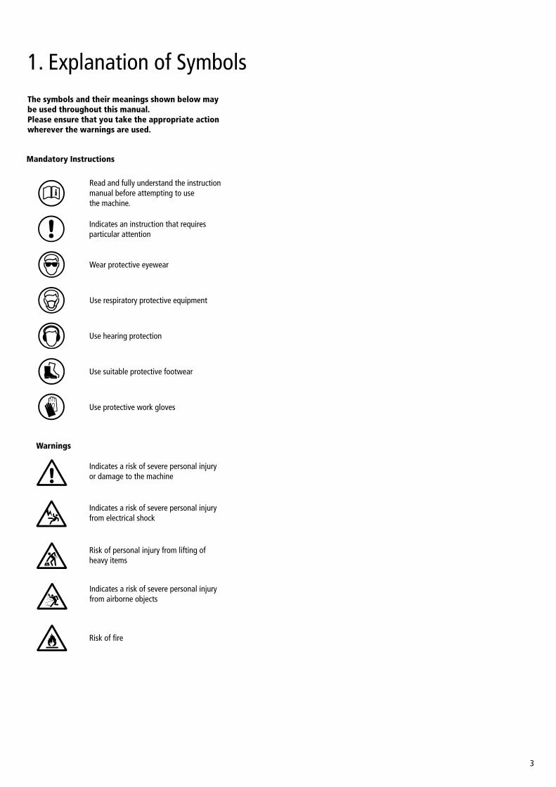
1. Explanation of SymbolsThe symbols and their meanings shown below may be used throughout this manual. Please ensure that you take the appropriate action wherever the warnings are used.
i
Kg
i
Kg
i
Kg i
Kg
i
Kg
i
Kg
i
Kg
i
Kg
Mandatory Instructions
Warnings
Read and fully understand the instruction manual before attempting to use the machine.
Indicates an instruction that requires particular attention
Wear protective eyewear
Use respiratory protective equipment
Use suitable protective footwear
Use hearing protection
Use protective work gloves
Indicates a risk of severe personal injury or damage to the machine
Indicates a risk of severe personal injury from electrical shock
Risk of personal injury from lifting of heavy items
Indicates a risk of severe personal injury from airborne objects
Risk of fire
i
Kg
i
Kg
i
Kg
i
Kg
4
2. General Health & Safety GuidanceEnsure that you carefully read and fully understand the instructions in this manual before assembly, installation and use of this product. Keep these instructions in a safe place for future reference.
WARNING: for your own safety, do not attempt to operate this machine until it is completely assembled and installed according to these instructions.
WARNING: When using any machine, basic safety precautions should always be followed to reduce the risk of fire, electric shock and personal injury.
Safe Operation
1. Use Personal Protective Equipment (PPE) • The operation of any machine can result in foreign objects being thrown
into your eyes, which can result in severe eye damage. Protective eyewear or other suitable eye protection or face shield should be used at all times. Everyday spectacles only have impact resistant lenses. They are not protective eyewear and do not give additional lateral protection.
• Use respiratory protective equipment (dust mask etc.) if the machining operation creates dust. Exposure to high levels of dust created by machining hardwoods, softwoods and man made composite boards can result in serious health problems. Some imported hardwoods give off highly irritating dust, which can cause a burning sensation. The use of respiratory protective equipment should not be seen as an alternative to controlling the risk of exposure at source by using adequate dust extraction equipment.
• The use of ear plugs or ear defenders is recommended when the machine is in use, particularly if the noise level exceeds 85 dB.
• Wear suitable protective gloves when handling cutting tools or blades. Gloves should NOT be worn when using the machine as they can be caught in moving parts of the machine.
• Non-slip safety footwear is recommended when using the machine and handling large work pieces.
2. Dress appropriately • Do not wear loose clothing, neckties or jewellery; they can be caught in
moving parts of the machine.
• Roll up long sleeves above the elbow.
• Wear protective hair covering to contain long hair.
3. Safety warnings • Find and read any warning labels on the machine
• It is important that any labels bearing health and safety warnings are not removed, defaced or covered. Replacement labels can be obtained by contacting our Customer Service Department.
4. Familiarise yourself with the machine • If you are not thoroughly familiar with the operation of this machine,
obtain advice from your supervisor, instructor, or other qualified person or contact your retailer for information on training courses. Do not use this machine until adequate training has been undertaken.
5. Take care when moving or positioning the machine • Some machines can be very heavy. Ensure the floor of the area
in which the machine is to be used is capable of supporting the machine.
• The machine and its various components can be heavy. Always adopt a safe lifting technique and seek assistance when lifting heavy components. In some cases it may be necessary to use mechanical handling equipment to position the machine within the work area.
• Some machines have optional wheel kits available to allow them to be manoeuvred around the workshop as required. Care should be taken to install these according to the instructions provided.
• Due to the nature of the design of some machines the centre of gravity will be high making them unstable when moved. Extreme care should be taken when moving any machine.
• If transportation of the machine is required then all precautions relating to the installation and handling of the machine apply. In addition, ensure that any vehicles or manual handling equipment used for transportation are of adequate specification.
6. The machine should be level and stable at all times • When using a leg stand or cabinet base that is designed to be fitted to
the machine, always ensure that it is securely fastened to the machine using the fixings provided.
• If the machine is suitable to be used on a workbench, ensure that the workbench is well constructed and capable of withstanding the weight of the machine. The machine should always be securely fastened to the workbench with appropriate fixings.
• Where possible, floor standing machines should always be secured to the floor with fixings appropriate to the structure of the floor.
• The floor surface should be sound and level. All of the feet of the machine should make contact with the floor surface. If they do not, either re-locate the machine to a more suitable position or use packing shims between the feet and the floor surface to ensure the machine is stable.
7. Remove adjusting keys and wrenches • Ensure that all adjusting wrenches and keys are removed before switching
the machine ‘ON’. There is a risk of severe personal injury or damage to the machine from airborne objects.
8. Before switching the machine ‘ON’ • Clear the machine table of all objects (tools, scrap pieces etc.)
• Make sure there is no debris between the work piece and the table / work support.
• Ensure that the work piece is not pressed against, or touching the saw blade or cutting tool.
• Check all clamps, work holding devices and fences to ensure that they are secure and cannot move during machining operations.
• Plan the way that you will hold and feed the work piece for the entire machining operation.
9. Whilst machining • Before starting work, watch the machine while it runs. If it makes
an unfamiliar noise or vibrates excessively, switch the machine ‘OFF’ immediately and disconnect it from the power supply. Do not restart until finding and correcting the source of the problem.
10. Keep the work area clear • Working clearances can be thought of as the distances between machines
and obstacles that allow safe operation of every machine without limitation. Consider existing and anticipated machine needs, size of material to be processed through each machine and space for auxiliary stands and/or work tables. Also consider the relative position of each machine to one another for efficient material handling. Be sure to allow yourself sufficient room to safely operate your machines in any foreseeable operation.
• Cluttered work areas and benches create the risk of accidents. Keep benches clear and tidy away tools that are not in use.
• Ensure that the floor area is kept clean and clear of any dust and debris that may create trip or slip hazards.
11. Consider the work area environment • Do not expose the machine to rain or damp conditions.
• Keep the work area well lit and ensure that there is artificial lighting available when there is insufficient natural light to effectively light the work area. Lighting should be bright enough to eliminate shadow and prevent eye strain.
• Do not use the machine in explosive environments eg. in the presence of flammable liquids, gases or dust.
• The presence of high levels of dust created by machining wood can present a risk of fire or explosion. Always use dust extraction equipment

5
to minimise the risk.
12. Keep other persons away (and pets) • The machine is designed to be used by one person only.
• Do not let persons, especially children, touch the machine or extension cable (if used) and keep visitors away from the work area.
• Never leave the machine running unattended. Turn the power supply off and do not leave the machine unattended until it comes to a complete stop.
• If the work area is to be left unattended, all machinery should be switched ‘OFF’ and isolated from the mains power supply.
13. Store machines safely when not in use • When not in use, machines should be stored in a dry place, out of reach
of children. Do not allow persons unfamiliar with these instructions or with the machine to operate it.
14. Do not overreach • Choose a working position that allows your body to remain balanced and
feed the work piece in to the machine without overreaching.
• Keep proper footing and balance at all times.
15. Electrical supply • Electrical circuits should be dedicated to each machine or large enough to
handle combined motor amp loads. Power outlets should be located near each machine so that power or extension cables are not obstructing high-traffic areas. Observe local electrical guidelines for proper installation of new lighting, power outlets, or circuits.
• The machine must be connected to an earthed power supply.
• The power supply must be equipped with a circuit breaker that provides short circuit, overload and earth leakage protection.
• The voltage of the machine must correspond to the voltage of the mains power supply.
• The mains plug fitted to the machine should always match the power outlet. Do not modify the plug in any way. If a replacement plug is required it should be fitted by a competent person and of the correct type and rating for the machine.
• If you are unsure about any electrical connections always consult a qualified electrician.
16. Avoid unintentional starting of the machine • Most machines are fitted with a no-volt release (NVR) switch to prevent
unintentional starting. If in doubt always ensure the machine switch is in the ‘OFF’ position before connecting it to the power supply. This means the machine will not automatically start up after a power cut or switching on of the power supply, unless you first reset the start switch.
17. Outdoor use • Your machine should not be used outdoors.
18. Extension cables • Whenever possible, the use of extension cables is not recommended.
If the use of an extension cable is unavoidable, then it should have a minimum core cross section of 2.5 mm² and limited to a maximum length of 3 metres.
• Extension cables should be routed away from the direct working area to prevent a trip hazard.
19. Guard against electric shock • Avoid body contact with earthed or grounded surfaces such as pipes
and radiators. There is an increased risk of electric shock if your body is earthed or grounded.
20. Always work within the machine’s intended capacities • Operator safety and machine performance are seriously adversely affected
if attempts to make the machine perform beyond its limits are made.
21. Do not abuse the power cable • Never pull the power cable to disconnect it from the power socket.
Always use the plug.
• Keep the power cable away from heat, oil and sharp edges.
• Do not use the power cable for carrying or moving the machine.
22. Secure the work piece • Ensure that the work piece is securely held before starting to machine it.
• When working within 300 mm of the machining area, always use a push stick to feed the work piece in to the blade or cutting tool. The push stick should have a minimum length of 400 mm. If the push stick becomes damaged, replace it immediately.
• Use extra supports (roller support stands etc.) for any work pieces large enough to tip when not held down to the table top.
• Do not use another person as a substitute for a table extension, or as additional support for a work piece that is longer or wider than the basic table, or to help feed, support, or pull the work piece.
• Do not attempt to machine more than one work piece at a time.
• When feeding the work piece towards the blade or cutting tool never position your hands in direct line of the cutting path. Avoid awkward operations and hand positions where a sudden slip could cause your hand or fingers to move into the machining area.
23. Stay alert • Safety is a combination of operator common sense and alertness at all
times when the machine is being used.
• Use all machines with extreme care and do not use the machine when you are tired or under the influence of drugs, alcohol or medication.
24. Use the correct tool for the job • Do not use the machine for any purpose other than which it
was designed.
• When selecting replacement cutting tools and blades, always ensure that they are designed to cut the material that you intend to use them for. If in any doubt seek further advice from the manufacturer.
25. Connect dust extraction equipment • Always use dust extraction equipment. The dust extractor should be of
suitable size and capacity for the machine that it is connected to and have a filtration level appropriate to the type of waste being collected. Refer to the relevant section of the manual for details of the specific dust extraction requirements for this machine.
• The dust extractor should be switched ‘ON’ before starting the machine that it is connected to. The dust extractor should be left running for 30 seconds after the last machining operation is complete in order to clear any residual waste from the machine.
26. Ensure that the machine is correctly guarded • Never use the machine if any of the standard safety guards and
equipment are removed or damaged.
• Some machines incorporate safety interlocks to prevent the machine from being used without the guards in place. Never attempt to bypass or modify the interlocks to allow the machine to be used without the guards in place.
27. Maintain your machine with care • This manual gives clear instructions on installation, set up and
operation of the machine and also details any routine and preventative maintenance that should be performed periodically by the user.
• Remember always to switch off and unplug the machine from the power supply before carrying out any setting up or maintenance operations.
• Follow any instructions for the maintenance of accessories and consumables.
• Do not use compressed air to clean the machine. Always use a brush to dislodge dust in places that are awkward to reach and a dust extractor to collect the waste.
• Inspect electric cables periodically and, if damaged, have them replaced by an authorised service facility or qualified electrician.
• Inspect extension cables (if used) periodically and replace if damaged.
2. General Health & Safety Guidance

6
28. Keep cutting tools sharp and clean • Correctly maintained cutting tools are easier to control and less likely
to bind.
• Cutting tools and blades can become hot during use. Take extreme care when handling them and always allow them to cool before changing, adjusting or sharpening them.
29. Disconnect the machine from the power supply • When not in use, before servicing, changing blades etc. always disconnect
the machine from the power supply.
30. Check for damaged parts • Before each use of the machine, it should be carefully checked to
determine that it will operate properly and perform its intended function.
• Check for alignment of moving parts, binding of moving parts, breakage of parts and any other conditions that may affect the operation of the machine.
• A guard or other part that is damaged should be properly repaired or replaced by a qualified person unless otherwise indicated in this instruction manual.
• Do not use the machine if the switch does not turn the machine ‘ON’ and ‘OFF’.
• Have defective switches replaced by a qualified person.
31. Warning! • The use of any accessory or attachment, other than those recommended
in this instruction manual, or recommended by our Company may present a risk of personal injury or damage to the machine and invalidation of the warranty.
32. Have your machine repaired by a qualified person • This machine complies with the relevant safety rules and standards
appropriate to its type when used in accordance with these instructions and with all of the standard safety guards and equipment in place. Only qualified persons using original spare parts should carry out repairs. Failure to do this may result in considerable danger to the user and invalidation of warranty.
33. Caution! Motor may become hot during use • It is normal for motors on some machines to become hot to the touch
during use. Avoid touching the motor directly when in use.
2. General Health & Safety Guidance

7
3. Record Power Guarantee“Products” means the Products sold by Record Power subject to these terms and conditions;
“Record Power” is Record Power Limited, whose company registration number is 4804158 and registered office address is Centenary House, 11 Midland Way, Barlborough Links, Chesterfield, Derbyshire, S43 4XA and sells through a network of Authorised Dealers;
“Authorised Distributor” is the nominated importer for your region who will generally sell through a network of Authorised Dealers. Details of Authorised Distributors for specific countries can be found in the Product manual or at www.recordpower.info;
“Authorised Dealer” is a retailer or business authorised to sell Record Power Products to end users.
1 Guarantee 1.1 Record Power guarantees that for a period of 5 years from the date
of purchase the components of qualifying Products (see clauses 1.2.1 to 1.2.9) will be free from defects caused by faulty construction or manufacture.
1.2 During this period Record Power, its Authorised Distributor or Authorised Dealer will repair or replace free of charge any parts which are proved to be faulty in accordance with paragraphs 1.1 above provided that:
1.2.1 you follow the claims procedure set out in clause 2 below;
1.2.2 Record Power, our Authorised Distributor or Authorised Dealer are given a reasonable opportunity after receiving notice of the claim to examine the Product;
1.2.3 if asked to do so by Record Power, its Authorised Distributor or Authorised Dealer, you return the Product, at your own cost, to Record Power’s premises or other approved premises such as those of the Authorised Distributor or supplying Authorised Dealer, for the examination to take place;
1.2.4 the fault in question is not caused by industrial use, accidental damage, fair wear and tear, wilful damage, neglect, incorrect electrical connection, abnormal working conditions, failure to follow our instructions, misuse, or alteration or repair of the Product without our approval;
1.2.5 the Product has been used in a domestic environment only;
1.2.6 the fault does not relate to consumable Products such as blades, bearings, drive belts or other wearing parts which can reasonably be expected to wear at different rates depending on usage (for full details contact Record Power or your local Authorised Distributor);
1.2.7 the Product has not been used for hire purposes, by you or by a previous owner;
1.2.8 the Product has been purchased by you as the guarantee is not transferable from a private sale.
1.2.9 where the Product has been purchased from a retailer, the 5 year guarantee is transferable and begins on the date of the first purchase of the Product and in the event of a claim under this guarantee proof of the original purchase date will be required to validate the warranty period.
2 Claims Procedure
2.1 In the first instance please contact the Authorised Dealer who supplied the Product to you. In our experience many initial problems with machines that are thought to be due to faulty parts are actually solved by correct setting up or adjustment of the machines. A good Authorised Dealer should be able to resolve the majority of these issues much more quickly than processing a claim under the guarantee.
2.2 Any damage to the Product resulting in a potential claim under the guarantee must be reported to the Authorised Dealer from which it was purchased within 48 hours of receipt.
2.3 If the Authorised Dealer who supplied the Product to you has been unable to satisfy your query, any claim made under this Guarantee should be made directly to Record Power or its Authorised Distributor (for details of the Authorised Distributor in your country please see your Product manual or check www.recordpower.info for details). The claim itself should be made in a letter setting out the date and place of purchase, and giving a brief explanation of the problem which has led to the claim. This letter should then be sent with proof of the purchase date (preferably a receipt) to Record Power or its Authorised Distributor. If you include a phone number or email address this will help to speed up your claim.
2.4 Please note that it is essential that the letter of claim reaches Record Power or its Authorised Distributor on the last day of this Guarantee at the latest. Late claims will not be considered.
3 Limitation of Liability 3.1 We only supply Products for domestic and private use. You agree not
to use the Product for any commercial, business or re-sale purposes and we have no liability to you for any loss of profit, loss of business, business interruption or loss of business opportunity.
3.2 This Guarantee does not confer any rights other than those expressly set out above and does not cover any claims for consequential loss or damage. This Guarantee is offered as an extra benefit and does not affect your statutory rights as a consumer.
4 Notice This Guarantee applies to all Products purchased from an Authorised
Dealer of Record Power within the United Kingdom of Great Britain and Northern Ireland. Terms of Guarantee may vary in other countries – please check with the Authorised Distributor in your country (details of the Authorised Distributor for your country can be found in the manual or at www.recordpower.info).
8
4. SpecificationsThroat depth: 102 mm
Depth of Feed: 50 mm
Chuck Capacity: 13 mm
Chuck to Table: 170 mm
Chuck to Base: 295 mm
Speeds: 500, 890, 1400, 1900 & 2500 rpm
Motor: ¼ hp
Chuck: 2 Morse taper / 13 mm
Size: H580 x W190 x D410 mm
Weight: 17 kg
Noise emission: Sound power level < 85 dB (A)
Sound pressure level < 85 dB (A)
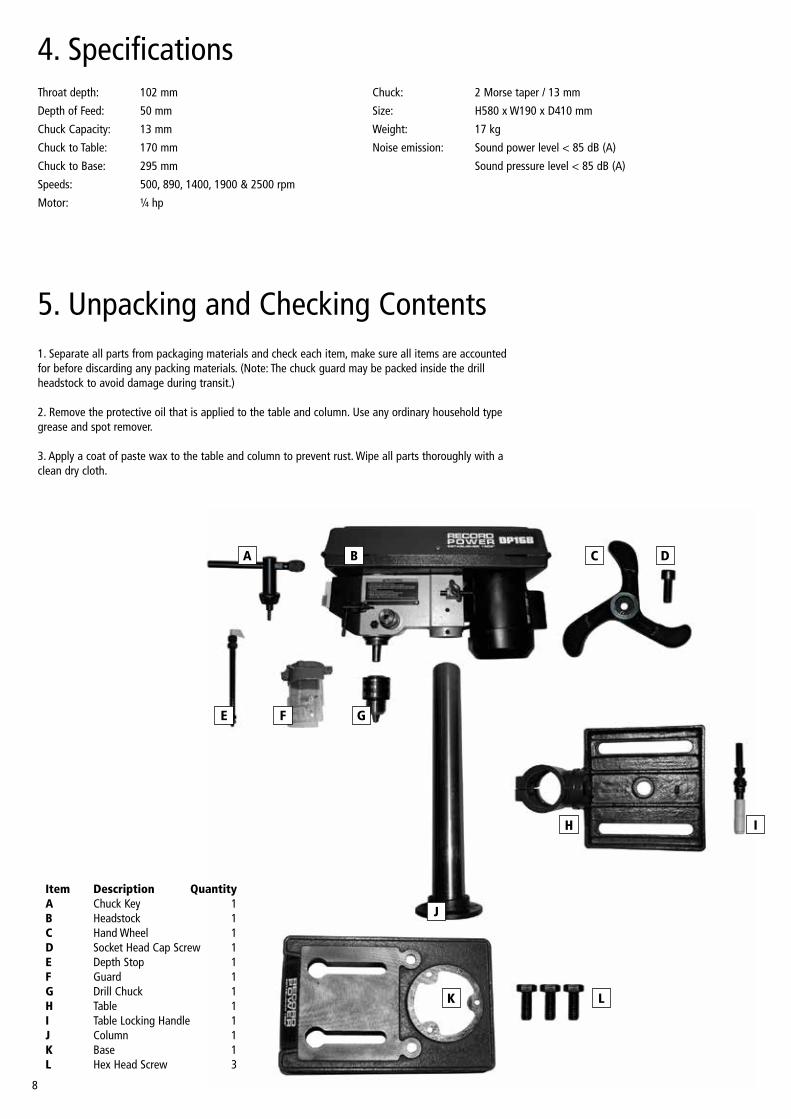
5. Unpacking and Checking Contents1. Separate all parts from packaging materials and check each item, make sure all items are accounted for before discarding any packing materials. (Note: The chuck guard may be packed inside the drill headstock to avoid damage during transit.)
2. Remove the protective oil that is applied to the table and column. Use any ordinary household type grease and spot remover.
3. Apply a coat of paste wax to the table and column to prevent rust. Wipe all parts thoroughly with a clean dry cloth.
B
J
G
A
E F
IH
Item Description QuantityA Chuck Key 1B Headstock 1C Hand Wheel 1D Socket Head Cap Screw 1E Depth Stop 1F Guard 1G Drill Chuck 1H Table 1I Table Locking Handle 1J Column 1K Base 1L Hex Head Screw 3
C D
K L

9
5. Unpacking and Checking Contents
6. Getting to Know Your Machine
Headstock
On/Off Switch
Guard
Table
Base
Hand Wheel
Motor
Column
Table Locking Handle
Chuck
Depth Stop
10
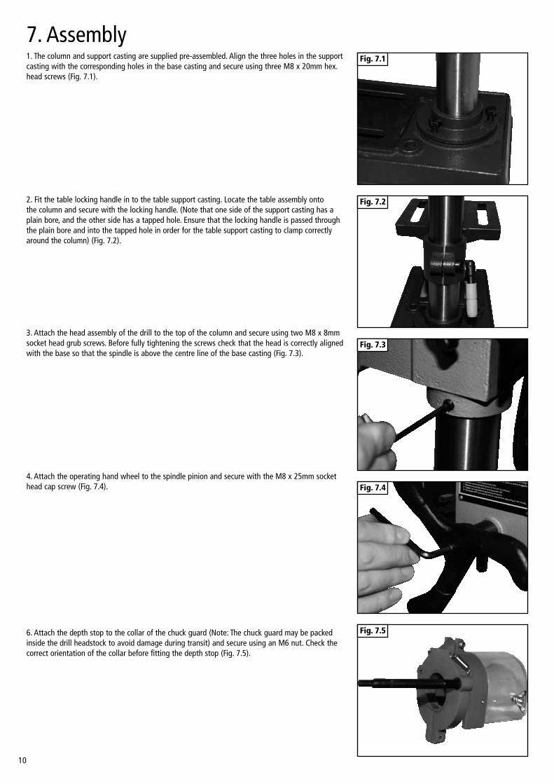
7. Assembly1. The column and support casting are supplied pre-assembled. Align the three holes in the support casting with the corresponding holes in the base casting and secure using three M8 x 20mm hex. head screws (Fig. 7.1).
2. Fit the table locking handle in to the table support casting. Locate the table assembly onto the column and secure with the locking handle. (Note that one side of the support casting has a plain bore, and the other side has a tapped hole. Ensure that the locking handle is passed through the plain bore and into the tapped hole in order for the table support casting to clamp correctly around the column) (Fig. 7.2).
3. Attach the head assembly of the drill to the top of the column and secure using two M8 x 8mm socket head grub screws. Before fully tightening the screws check that the head is correctly aligned with the base so that the spindle is above the centre line of the base casting (Fig. 7.3).
4. Attach the operating hand wheel to the spindle pinion and secure with the M8 x 25mm socket head cap screw (Fig. 7.4).
Fig. 7.1
Fig. 7.2
Fig. 7.3
Fig. 7.4
6. Attach the depth stop to the collar of the chuck guard (Note: The chuck guard may be packed inside the drill headstock to avoid damage during transit) and secure using an M6 nut. Check the correct orientation of the collar before fitting the depth stop (Fig. 7.5).
Fig. 7.5
11
Fig. 7.7
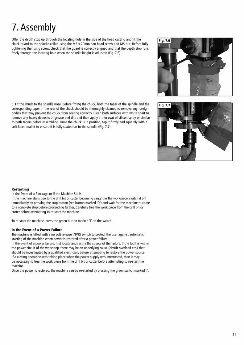
Fig. 7.6Offer the depth stop up through the locating hole in the side of the head casting and fit the chuck guard to the spindle collar using the M5 x 20mm pan head screw and M5 nut. Before fully tightening the fixing screw, check that the guard is correctly aligned and that the depth stop runs freely through the locating hole when the spindle height is adjusted (Fig. 7.6).
5. Fit the chuck to the spindle nose. Before fitting the chuck, both the taper of the spindle and the corresponding taper in the rear of the chuck should be thoroughly cleaned to remove any foreign bodies that may prevent the chuck from seating correctly. Clean both surfaces with white spirit to remove any heavy deposits of grease and dirt and then apply a thin coat of silicon spray or similar to both tapers before assembling. Once the chuck is in position, tap it firmly and squarely with a soft faced mallet to ensure it is fully seated on to the spindle (Fig. 7.7).
RestartingIn the Event of a Blockage or if the Machine StallsIf the machine stalls due to the drill bit or cutter becoming caught in the workpiece, switch it off immediately by pressing the stop button (red button marked ‘O’) and wait for the machine to come to a complete stop before proceeding further. Carefully free the work piece from the drill bit or cutter before attempting to re-start the machine.
To re-start the machine, press the green button marked ‘I’ on the switch. In the Event of a Power FailureThe machine is fitted with a no volt release (NVR) switch to protect the user against automatic starting of the machine when power is restored after a power failure.In the event of a power failure, first locate and rectify the source of the failure. If the fault is within the power circuit of the workshop, there may be an underlying cause (circuit overload etc.) that should be investigated by a qualified electrician, before attempting to restore the power source.If a cutting operation was taking place when the power supply was interrupted, then it may be necessary to free the work piece from the drill bit or cutter before attempting to re-start the machine.Once the power is restored, the machine can be re-started by pressing the green switch marked ‘I’.
7. Assembly
12
8. Maintenance
Checking Belt Tension and Changing Speed Setting
Before attempting to use the machine, check that the correct speed is selected in relation to the size and type of drill bit and type of material being machined. It is important to apply the correct level of tension, over tensioning the belt will apply excessive load to the motor and spindle bearings and may cause damage to the machine. Insufficient tensioning of the belt will cause the machine to be noisy as there will be excess movement of the belt as it runs between the pulleys and the spindle may stall when machining as pressure is applied to the work piece. Periodically check the belt tension to maintain optimum performance of the machine.
Before attempting any maintenance or adjustment ALWAYS ensure that the machine is disconnected from the power supply.
Changing the Speed Setting
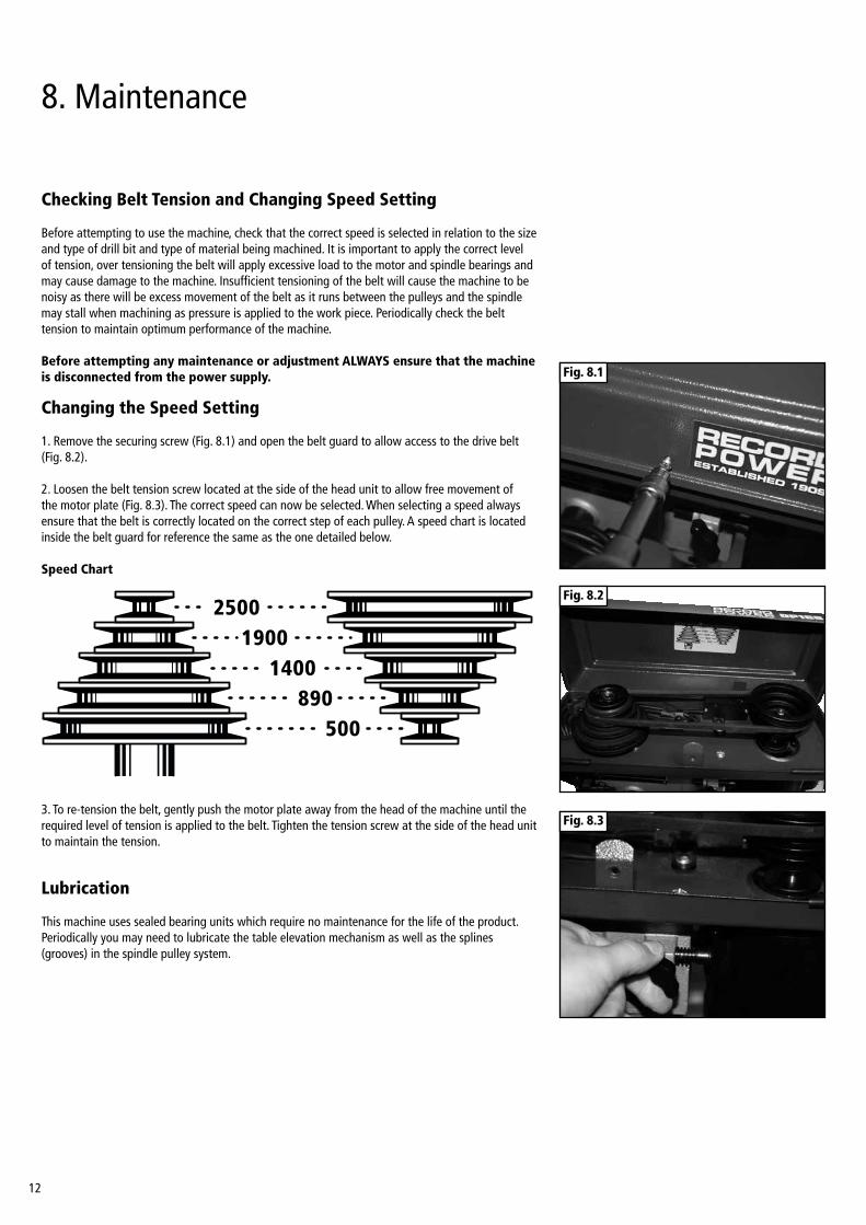
1. Remove the securing screw (Fig. 8.1) and open the belt guard to allow access to the drive belt (Fig. 8.2).
2. Loosen the belt tension screw located at the side of the head unit to allow free movement of the motor plate (Fig. 8.3). The correct speed can now be selected. When selecting a speed always ensure that the belt is correctly located on the correct step of each pulley. A speed chart is located inside the belt guard for reference the same as the one detailed below.
Speed Chart
3. To re-tension the belt, gently push the motor plate away from the head of the machine until the required level of tension is applied to the belt. Tighten the tension screw at the side of the head unit to maintain the tension.
Lubrication
This machine uses sealed bearing units which require no maintenance for the life of the product.Periodically you may need to lubricate the table elevation mechanism as well as the splines (grooves) in the spindle pulley system.
Fig. 8.1
Fig. 8.2
Fig. 8.3
13
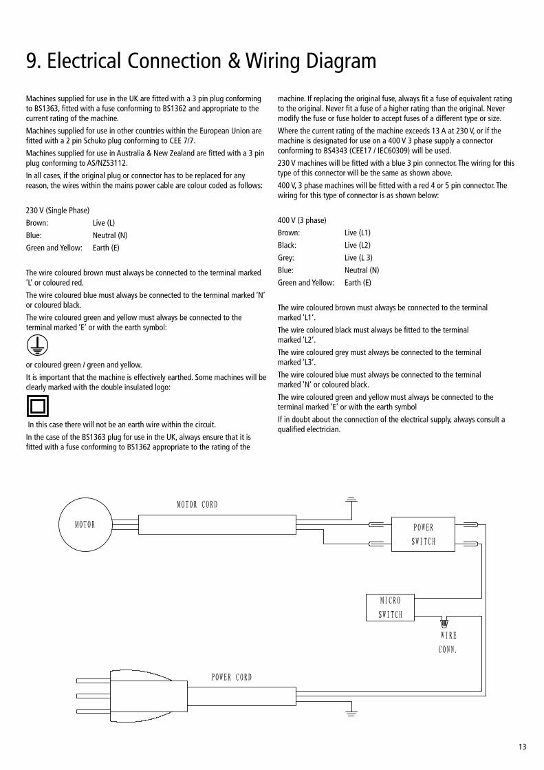
9. Electrical Connection & Wiring Diagram
MICRO
SWITCH
POWER
SWITCH
MOTOR
POWER CORD
MOTOR CORD
WIRE
CONN.
Machines supplied for use in the UK are fitted with a 3 pin plug conforming to BS1363, fitted with a fuse conforming to BS1362 and appropriate to the current rating of the machine.
Machines supplied for use in other countries within the European Union are fitted with a 2 pin Schuko plug conforming to CEE 7/7.
Machines supplied for use in Australia & New Zealand are fitted with a 3 pin plug conforming to AS/NZS3112.
In all cases, if the original plug or connector has to be replaced for any reason, the wires within the mains power cable are colour coded as follows:
230 V (Single Phase)
Brown: Live (L)
Blue: Neutral (N)
Green and Yellow: Earth (E)
The wire coloured brown must always be connected to the terminal marked ‘L’ or coloured red.
The wire coloured blue must always be connected to the terminal marked ‘N’ or coloured black.
The wire coloured green and yellow must always be connected to the terminal marked ‘E’ or with the earth symbol:
or coloured green / green and yellow.
It is important that the machine is effectively earthed. Some machines will be clearly marked with the double insulated logo:
In this case there will not be an earth wire within the circuit.
In the case of the BS1363 plug for use in the UK, always ensure that it is fitted with a fuse conforming to BS1362 appropriate to the rating of the
machine. If replacing the original fuse, always fit a fuse of equivalent rating to the original. Never fit a fuse of a higher rating than the original. Never modify the fuse or fuse holder to accept fuses of a different type or size.
Where the current rating of the machine exceeds 13 A at 230 V, or if the machine is designated for use on a 400 V 3 phase supply a connector conforming to BS4343 (CEE17 / IEC60309) will be used.
230 V machines will be fitted with a blue 3 pin connector. The wiring for this type of this connector will be the same as shown above.
400 V, 3 phase machines will be fitted with a red 4 or 5 pin connector. The wiring for this type of connector is as shown below:
400 V (3 phase)
Brown: Live (L1)
Black: Live (L2)
Grey: Live (L 3)
Blue: Neutral (N)
Green and Yellow: Earth (E)
The wire coloured brown must always be connected to the terminal marked ‘L1’.
The wire coloured black must always be fitted to the terminal marked ‘L2’.
The wire coloured grey must always be connected to the terminal marked ‘L3’.
The wire coloured blue must always be connected to the terminal marked ‘N’ or coloured black.
The wire coloured green and yellow must always be connected to the terminal marked ‘E’ or with the earth symbol
If in doubt about the connection of the electrical supply, always consult a qualified electrician.

14
10. Troubleshooting
Problem Cause Remedy
Noisy operation 1. Incorrect belt tension 1. Adjust tension 2. Dry spindle 2. Lubricate spindle 3. Loose spindle pulley 3. Check tightness of retaining nut on pulley
and tighten if necessary 4. Loose motor pulley 4. Tighten set screws in pulleys
Drill bit burns 1. Incorrect speed 1. Change speed 2. Chips not coming out of hole 2. Retract drill bit frequently to clear chips 3. Dull drill bit 3. Resharpen drill bit 4. Feeding too slow 4. Change speed 5. Not lubricated 5. Lubricate drill bit
Drill bit leads off or hole not circular 1. Hard grain in wood 1. Resharpen drill bit correctly 2. Lengths of cutting lips and/or angles not equal 2. Resharpen drill bit correctly 3. Bent drill bit 3. Replace drill bit
Wood splinters on underside 1. No “back up material” under workpiece 1. Use “back up material”
Workpiece turns loose from hand 1. Not supported or clamped properly 1. Support workpiece or clamp it
Drill bit binds in workpiece 1. Workpiece pinching drill bit 1. Support workpiece or clamp it or excessive feed pressure 2. Improper belt tension 2. Adjust tension
Excessive drill bit run out or wobble 1. Bent drill bit 1. Replace drill bit 2. Worn spindle bearings 2. Replace bearings 3. Drill bit not properly installed in chuck 3. Install drill bit properly 4. Chuck not properly installed 4. Install chuck properly
Quill returns too slow or too fast 1. Spring has improper tension 1. Adjust spring tension
Chuck will not stay attached to spindle, 1. Dirt, grease or oil on the tapered inside surface 1. Using a household detergent, clean the taperedit falls off when trying to install of chuck or on the tapered surface of the spindle surface of the chuck and spindle to remove all dirt, grease and oil

15
11. Parts List & Diagrams
No. Description
123456789101112131415
Bushing Rubber KnobKnobScrew-Pan Head M5 x 0.8-12V-Belt 5/16 x 26Guard with LabelsScrew - Washer Head M6 X 1.0-16Retaining Ring17mm Ball BearingSpacerInsert PulleyPulley SpindleNut PulleyClamp CordScrew Pan Head M5 x 0.8-16Foam Washer
16
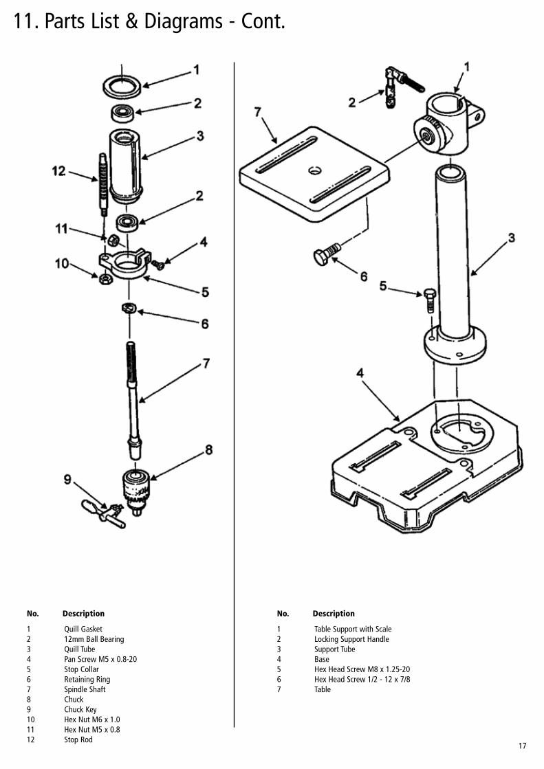
11. Parts List & Diagrams - Cont.
No. Description
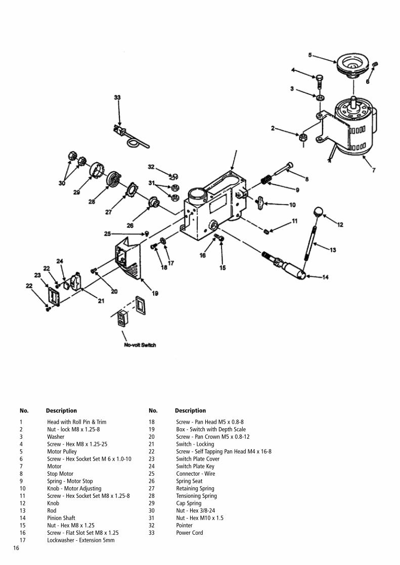
1234567891011121314151617
Head with Roll Pin & TrimNut - lock M8 x 1.25-8WasherScrew - Hex M8 x 1.25-25Motor PulleyScrew - Hex Socket Set M 6 x 1.0-10MotorStop MotorSpring - Motor StopKnob - Motor AdjustingScrew - Hex Socket Set M8 x 1.25-8KnobRodPinion ShaftNut - Hex M8 x 1.25Screw - Flat Slot Set M8 x 1.25Lockwasher - Extension 5mm
No. Description
18192021222324252627282930313233
Screw - Pan Head M5 x 0.8-8Box - Switch with Depth ScaleScrew - Pan Crown M5 x 0.8-12Switch - LockingScrew - Self Tapping Pan Head M4 x 16-8Switch Plate CoverSwitch Plate KeyConnector - WireSpring SeatRetaining SpringTensioning SpringCap SpringNut - Hex 3/8-24Nut - Hex M10 x 1.5PointerPower Cord
17
11. Parts List & Diagrams - Cont.
11. Parts List & Diagrams - Cont.
No. Description
123456789101112
Quill Gasket12mm Ball BearingQuill TubePan Screw M5 x 0.8-20Stop CollarRetaining RingSpindle ShaftChuckChuck KeyHex Nut M6 x 1.0Hex Nut M5 x 0.8Stop Rod
No. Description
1234567
Table Support with ScaleLocking Support HandleSupport TubeBaseHex Head Screw M8 x 1.25-20Hex Head Screw 1/2 - 12 x 7/8Table

18
EU Declaration Of Conformity
Cert No: EU / DP16B / 1
Record Power Ltd, Centenary House, 11 Midland Way, Barlborough Links, Chesterfield, Derbyshire S43 4XAdeclares that the machinery described:-
1. Type: Drill Press
2. Model No: DP16B
3. Serial No .........................................................................
Conforms with the following directives:- Machinery Directive: 2006/42/EC EN61029-1:2009+A11:2010 Low Voltage Directive: 2006/95/EC EN55014-1:2006+A1:2009 EN55014-2:1997+A1:2001+A2:2008 EN61000-3-2:2006+A1:2009+A2:2009 EN61000-3-3:2008 Electromagnetic Compatibility: 2004/108/EC Certificate Numbers: SH10080480-001,SH10080480-002,SH10080481-001 Issued by: Intertek Testing Services Shanghai, Building No.86, 1198 Qinzhou Road (North), Caoheling Development Zone, Shanghai 200233, China.and complies with the relevant essential health and safety requirements.
Signed.............................................................. Dated: 01/08/2014
Andrew GreenstedManaging Director

19

Woodworking Machinery & Accessories
United KingdomRecord Power Ltd
Centenary House, 11 Midland Way Barlborough Links, Chesterfield Derbyshire S43 4XA
Tel: 01246 571 020 Fax: 01246 571 030
www.recordpower.co.uk
EireRecord Power Ltd
Centenary House, 11 Midland Way Barlborough Links, Chesterfield Derbyshire S43 4XA
Tel: 01246 571 020 Fax: 01246 571 030
www.recordpower.co.uk
AustraliaTools 4 Industry
Po Box 3844 Parramatta 2124
Tel: 1300 124 422 Fax: 1800 262 725
www.recordpower.com.au
New ZealandTools 4 Industry
Po Box 276079 Manukau City 2241
Tel: 0800 142 326 Fax: 09 2717 237
www.recordpower.co.nz
Made in China