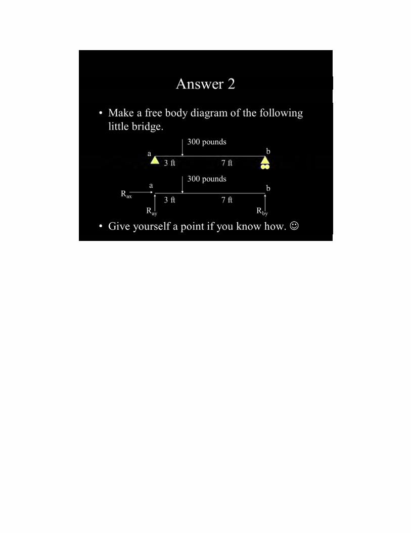
Ben used this exercise to get some balanced homework ... · a cantilever with a slanted support...
128
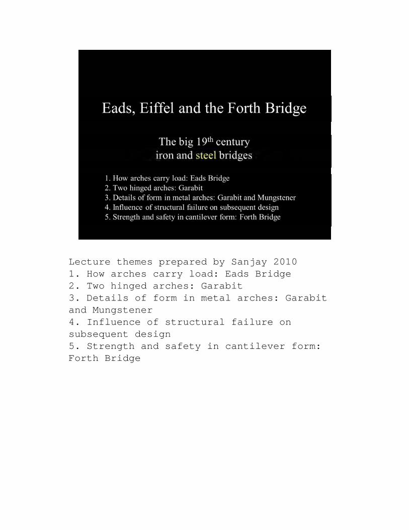
Lecture themes prepared by Sanjay 2010 1. How arches carry load: Eads Bridge 2. Two hinged arches: Garabit 3. Details of form in metal arches: Garabit and Mungstener 4. Influence of structural failure on subsequent design 5. Strength and safety in cantilever form: Forth Bridge
Transcript of Ben used this exercise to get some balanced homework ... · a cantilever with a slanted support...
Lecture themes prepared by Sanjay 20101. How arches carry load: Eads Bridge2. Two hinged arches: Garabit3. Details of form in metal arches: Garabit and Mungstener4. Influence of structural failure on subsequent design5. Strength and safety in cantilever form: Forth Bridge
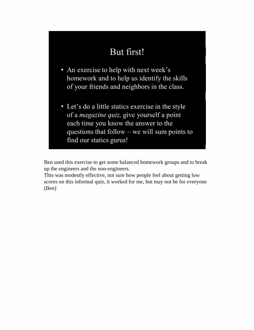
Ben used this exercise to get some balanced homework groups and to break up the engineers and the non-engineers.This was modestly effective, not sure how people feel about getting low scores on this informal quiz, it worked for me, but may not be for everyone (Ben)


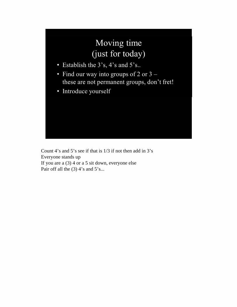
Count 4’s and 5’s see if that is 1/3 if not then add in 3’sEveryone stands upIf you are a (3) 4 or a 5 sit down, everyone elsePair off all the (3) 4’s and 5’s...

Count 4’s and 5’s see if that is 1/3 if not then add in 3’sEveryone stands upIf you are a (3) 4 or a 5 sit down, everyone elsePair off all the (3) 4’s and 5’s...
Structural Study from Lecture 3 presented now -- maybe break that little bit into a separate supplement.
Ben, Your slide had them do the assignment in groups. I deleted that and will do individually. You can add back in if you like.

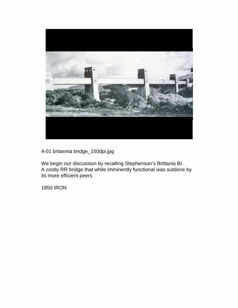
4-01 britannia bridge_150dpi.jpg
We begin our discussion by recalling Stephenson’s Brittania Br.A costly RR bridge that while imminently functional was outdone by its more efficient peers
1850 IRON
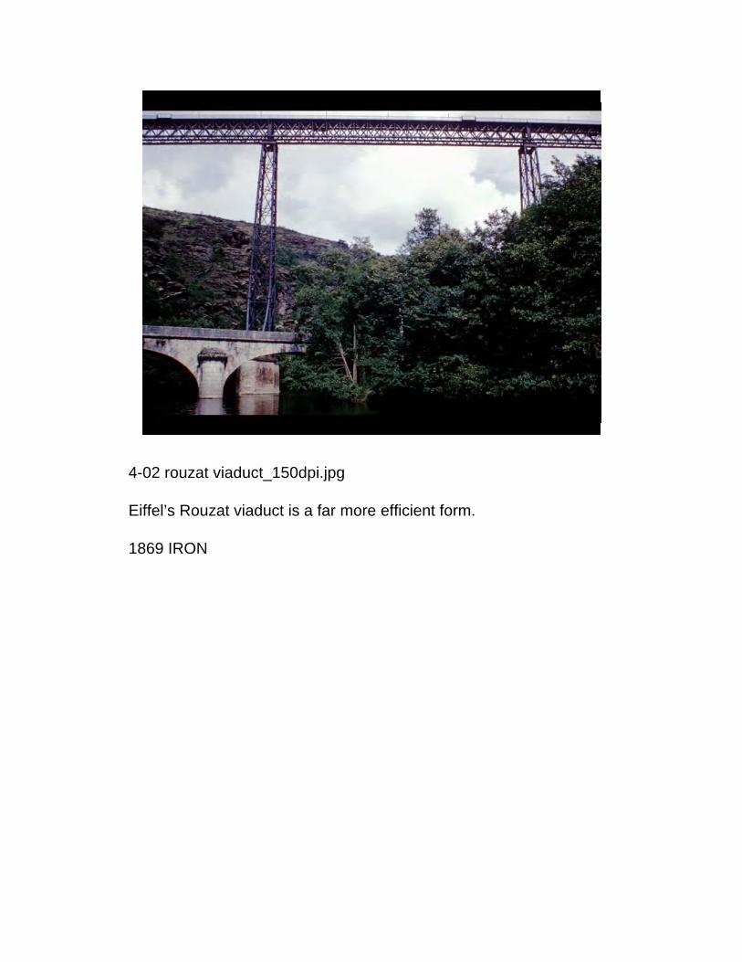
4-02 rouzat viaduct_150dpi.jpg
Eiffel’s Rouzat viaduct is a far more efficient form.
1869 IRON

4-03 saltash (royal albert) bridge _150dpi.jpg
Even Brunel’s Saltash (Royal Albert) Br. provides a more efficient solution (about ½ the weight of Brittania)
1856 IRON

4-04 bridge over north elbe_150dpi.jpg
the Germans copied the Saltash over the North Elbe but with heavy decorative towers strange to our eyesalso without any distinction between the compression and tension members
(2007 structurae shows a new lenticular over the North Elbe in Hamburg, perhaps a replacement for this..)

4-05 bridge over rhine at coblenz_150dpi.jpg
Returning to Germany we see the motivation for one of the most impressive steel bridges of its era
Here is the Koblenz Br., completed in 1878 (date must be wrong b/c it should be before 1874 Eads!) and destroyed in 1945 (structurae)Google books points to Arch Bridges, Anna Sinopili ed. that gives 1862-1864 as the construction date.
The model and motivation for the Eads Br. in St. Louis

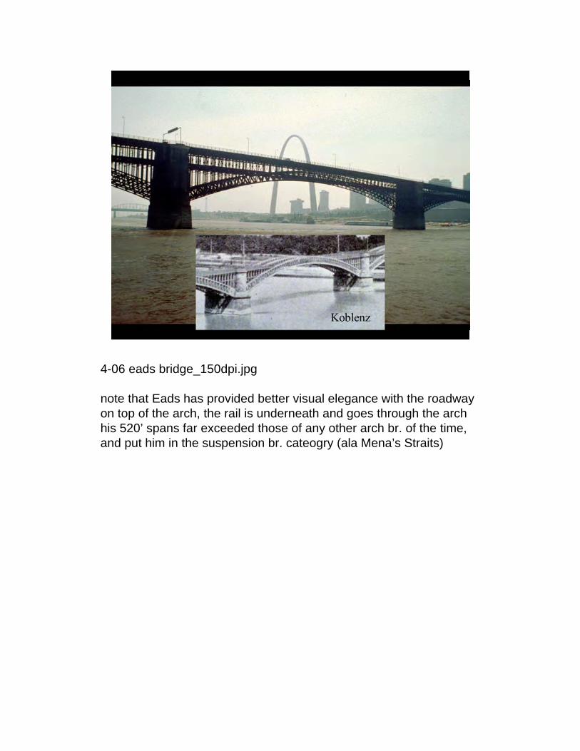
4-06 eads bridge_150dpi.jpg
Despite our admonitions the arch still stands in the background, in the foregorund we find Eads Br.the first major steel bridge and the longest arch bridge in the world at its completion
4-06 eads bridge_150dpi.jpg
note that Eads has provided better visual elegance with the roadway on top of the arch, the rail is underneath and goes through the archhis 520’ spans far exceeded those of any other arch br. of the time, and put him in the suspension br. cateogry (ala Mena’s Straits)
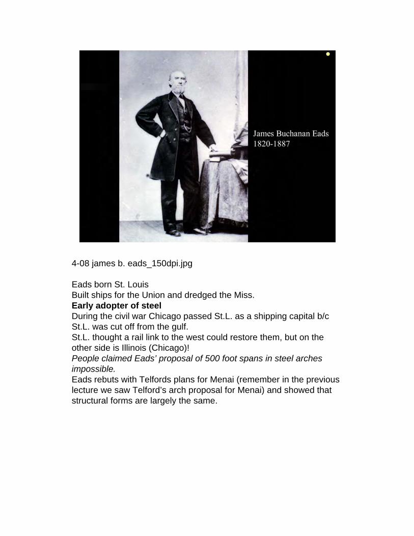
4-08 james b. eads_150dpi.jpg
Eads born St. LouisBuilt ships for the Union and dredged the Miss.Early adopter of steelDuring the civil war Chicago passed St.L. as a shipping capital b/c St.L. was cut off from the gulf.St.L. thought a rail link to the west could restore them, but on the other side is Illinois (Chicago)!People claimed Eads’ proposal of 500 foot spans in steel arches impossible.Eads rebuts with Telfords plans for Menai (remember in the previous lecture we saw Telford’s arch proposal for Menai) and showed that structural forms are largely the same.
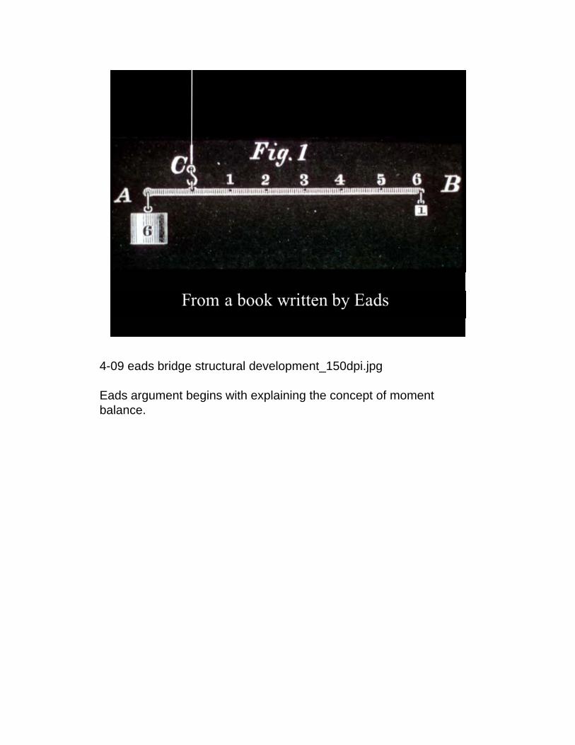
4-09 eads bridge structural development_150dpi.jpg
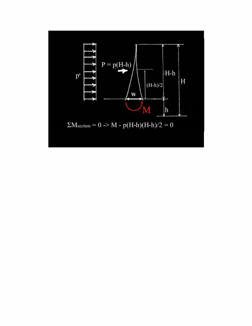
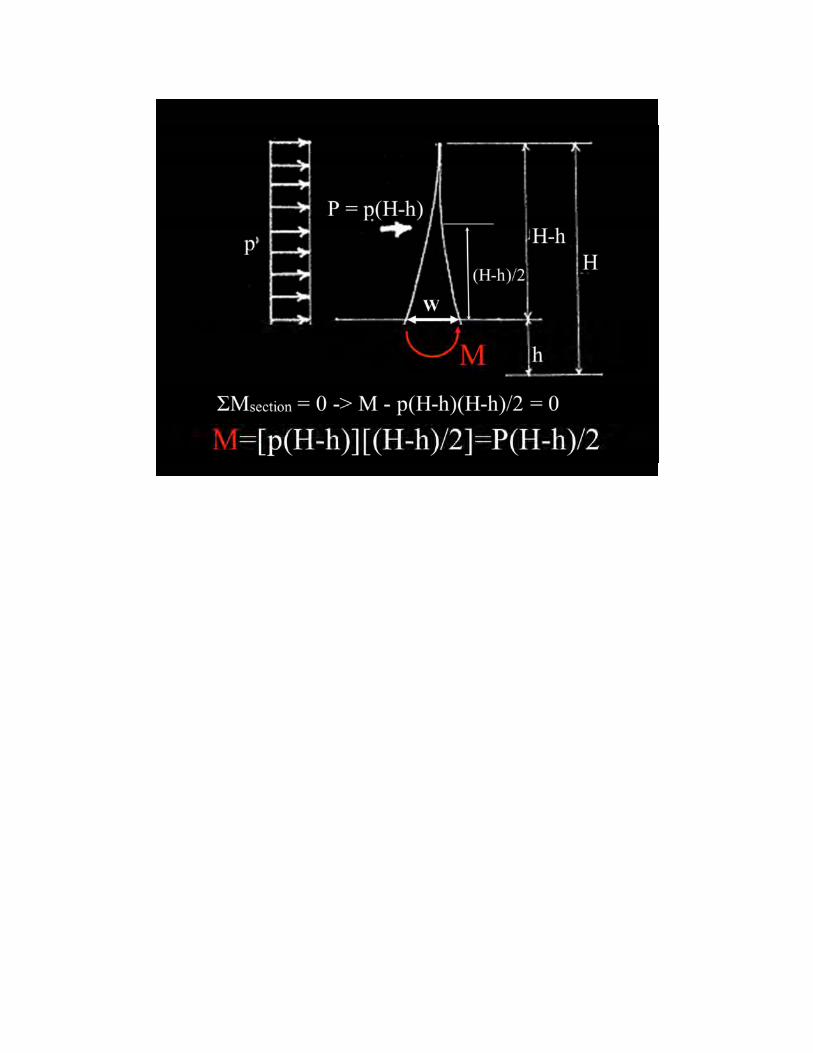
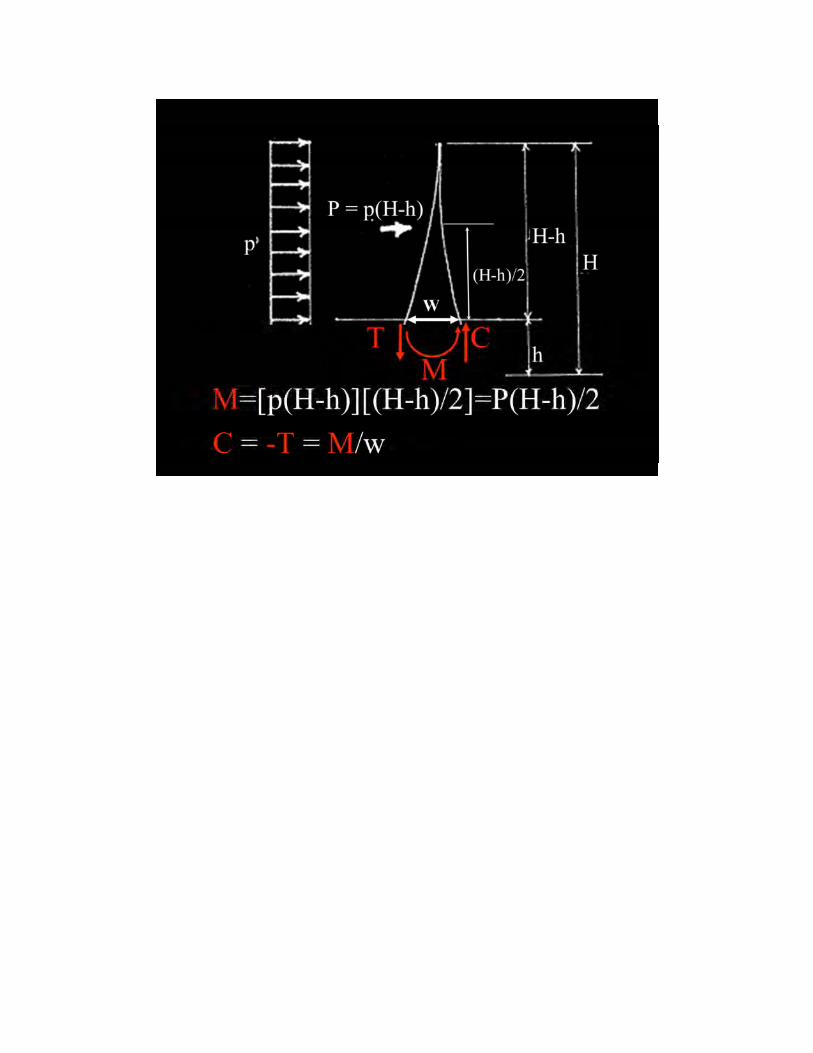
Eads argument begins with explaining the concept of moment balance.

4-09 eads bridge structural development_150dpi.jpg
Eads argument begins with explaining the concept of moment balance.

June 7th 2005 reinstallation of Calder’s Mobile at the National galleryhttp://www.nga.gov/collection/calder/calder-ss1.shtm

4-10 eads bridge structural development_150dpi.jpg
a cantilever with a slanted support requires a horizontal reaction to balance the structure
this is the original “canted” “lever”

4-11 eads bridge structural development_150dpi.jpg
If we put two of these together the slanted support is no longer needed if a horizontal tie is used to take the horizontal reaction2 cantilevers with a tie demonstrate his arch
(Would be nice to rescan these from the original and make them much nicer..)

4-12 eads bridge structural development_150dpi.jpg
this development leads directly to ideas of a truss where the top chord is in compression and the bottom is in tensiondiagonals make the entire structure stable… (the building block of trusses)
4-13 eads bridge structural development_150dpi.jpg
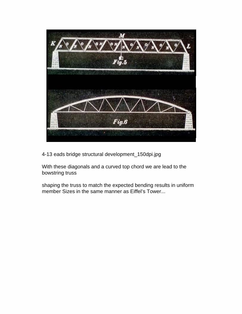
With these diagonals and a curved top chord we are lead to the bowstring truss
shaping the truss to match the expected bending results in uniform member Sizes in the same manner as Eiffel’s Tower...

4-14 eads bridge structural development_150dpi.jpg
if the bottom tie is replaced by rigid abutments we find a simple arch.
admittedly this is a bit of a circuitous route – but the point was to connect all these forms in a manner that makes it clear that their separation is largely artificial and not a fact of nature as Eads critics would put forth in selecting one form over another.
4-15 eads bridge structural development_150dpi.jpg
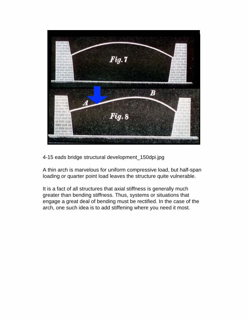
A thin arch is marvelous for uniform compressive load, but half-span loading or quarter point load leaves the structure quite vulnerable.
It is a fact of all structures that axial stiffness is generally much greater than bending stiffness. Thus, systems or situations that engage a great deal of bending must be rectified. In the case of the arch, one such idea is to add stiffening where you need it most.
4-16 eads bridge structural development_150dpi.jpg
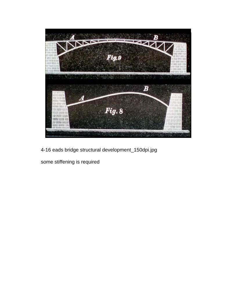
some stiffening is required
4-17 eads bridge structural development_150dpi.jpg
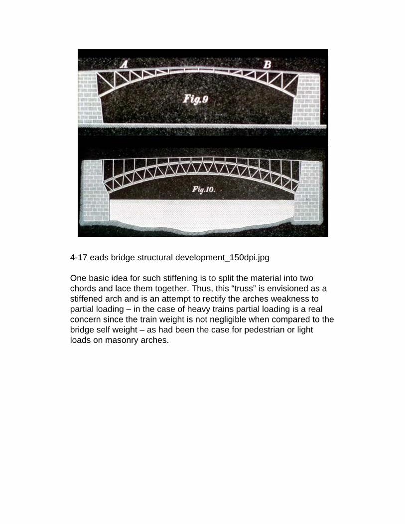
One basic idea for such stiffening is to split the material into two chords and lace them together. Thus, this “truss” is envisioned as a stiffened arch and is an attempt to rectify the arches weakness to partial loading – in the case of heavy trains partial loading is a real concern since the train weight is not negligible when compared to the bridge self weight – as had been the case for pedestrian or light loads on masonry arches.

4-18 eads bridge elevation_150dpi.jpg
Here we see the proposal for the Eads bridge

4-19 eads bridge springing_150dpi.jpg
Here we see the completed bridge which carried heavy rail until its mid 2000’s restoration and now serves the city via Metrolink, the city light rail.Clearly this adaptive re-use is a testament to Eads, to St. Louis, and suggests high marks in the social cateogry for the bridge (or at least heading in the right direction).. if you run over the bridge their is little to see on the Illinois side save from highways and a dirty casino (sorry but true)

juxtaposing the previous two images together we get a sense of the minor tweaking, but overall success of the proposal

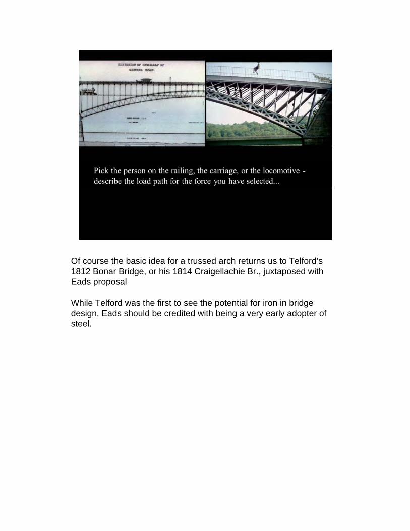
Of course the basic idea for a trussed arch returns us to Telford’s 1812 Bonar Bridge, or his 1814 Craigellachie Br., juxtaposed with Eads proposal
While Telford was the first to see the potential for iron in bridge design, Eads should be credited with being a very early adopter of steel.
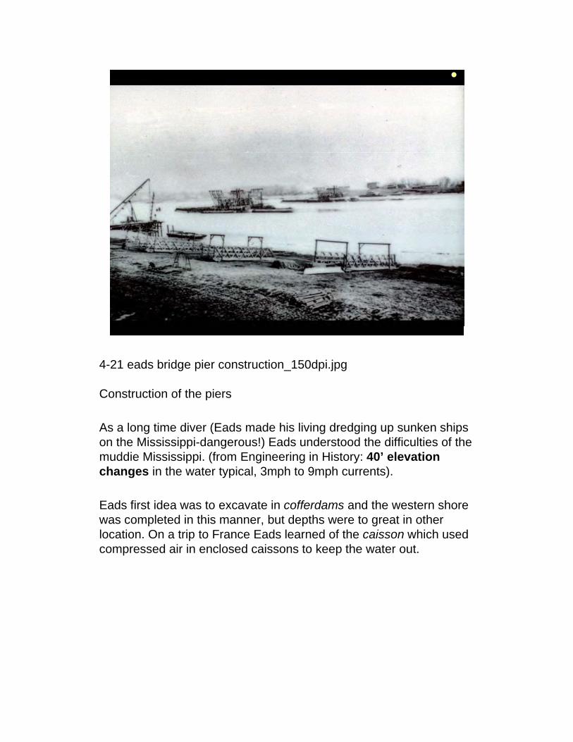
4-21 eads bridge pier construction_150dpi.jpg
Construction of the piers
As a long time diver (Eads made his living dredging up sunken ships on the Mississippi-dangerous!) Eads understood the difficulties of the muddie Mississippi. (from Engineering in History: 40’ elevation changes in the water typical, 3mph to 9mph currents).
Eads first idea was to excavate in cofferdams and the western shore was completed in this manner, but depths were to great in other location. On a trip to France Eads learned of the caisson which used compressed air in enclosed caissons to keep the water out.
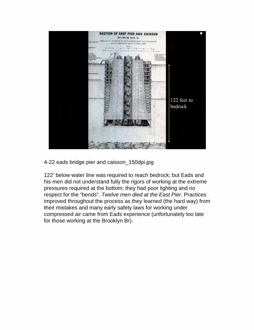
4-22 eads bridge pier and caisson_150dpi.jpg
122’ below water line was required to reach bedrock; but Eads and his men did not understand fully the rigors of working at the extreme pressures required at the bottom; they had poor lighting and no respect for the “bends”. Twelve men died at the East Pier. Practices improved throughout the process as they learned (the hard way) from their mistakes and many early safety laws for working under compressed air came from Eads experience (unfortunately too late for those working at the Brooklyn Br).
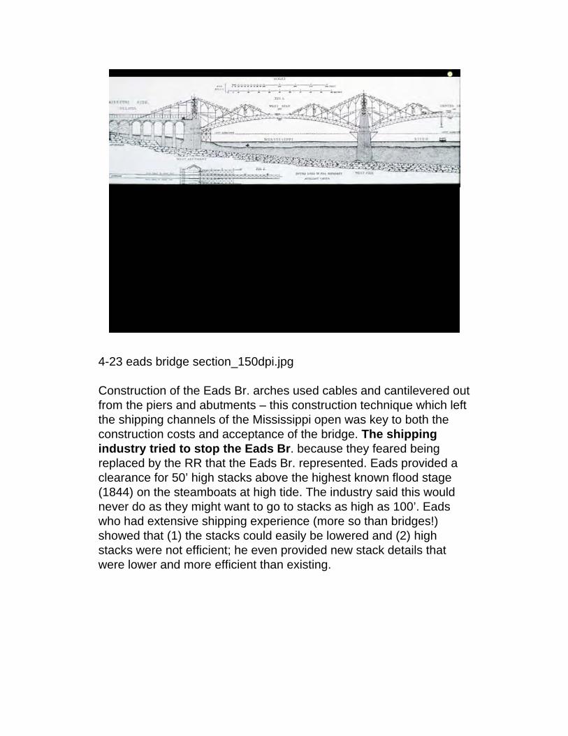
4-23 eads bridge section_150dpi.jpg
Construction of the Eads Br. arches used cables and cantilevered out from the piers and abutments – this construction technique which left the shipping channels of the Mississippi open was key to both the construction costs and acceptance of the bridge. The shipping industry tried to stop the Eads Br. because they feared being replaced by the RR that the Eads Br. represented. Eads provided a clearance for 50’ high stacks above the highest known flood stage (1844) on the steamboats at high tide. The industry said this would never do as they might want to go to stacks as high as 100’. Eads who had extensive shipping experience (more so than bridges!) showed that (1) the stacks could easily be lowered and (2) high stacks were not efficient; he even provided new stack details that were lower and more efficient than existing.

4-23 eads bridge section_150dpi.jpg4-24 menai arch construction_150dpi.jpg
Eads was a student of history and was aware of Telford’s proposal for an arch at Menai, he used the example to ridicule those who suggested arches could not be done at this span – he also used Telford’s ideas for easing construction.

4-26 section from original eads bridge tube_150dpi.jpg
Here we see a section from the original bridge and see how the segmental tube with the collar was actually constructed.
18 in. dia, 12 ft. long – 600 of these staves – like the staves of a barrelfy = 50ksi, fu=120ksi – Eads was brutal on his suppliers ensuring that the quality he desired was met.(this steel meets or exceeds most modern Steels in use today)

4-27 eads bridge construction, stereopticon view_150dpi.jpg
Sterioopticon photos, popular at the time (1873-1874) provide views of the Eads under construction

4-28 eads bridge construction, stereopticon view_150dpi.jpg
But what if it doesn’t fit when they come together? With thermal movements predicted as much as 8 in. it was a real concern and indeed, on site the lat tubular section was just too long and would not fit. The on-site engineer packed the final tube with ice and “hoped the weather god would join his staff” (Kirby et al.). Eads has already designed a final section which could be Screwed in to place and of adjustable length – the arch was closed and more funding for the bridges completion secured.

4-29 eads bridge construction, stereopticon view_150dpi.jpg

4-30 eads bridge construction, stereopticon view_150dpi.jpg

4-31 eads bridge print by currier and ives_150dpi.jpg
The completed bridge was a favorite for engravings of the time, here we see the engines of St. Louis commerce along with its people enjoying the bridge. Assuming the bridge is to scale you might imagie stacks twice as high on the steamboats…
The Bridge was envisioned as a ticket to St. Louis greatness (particularly over Chicago) and attempts to bring lost commerce from the civil war from Chicago back to St Louis.

4-32 saint louis, future great city of the world_150dpi.jpg
Reavis’s 1871 book envisioned the St. Louis of the future
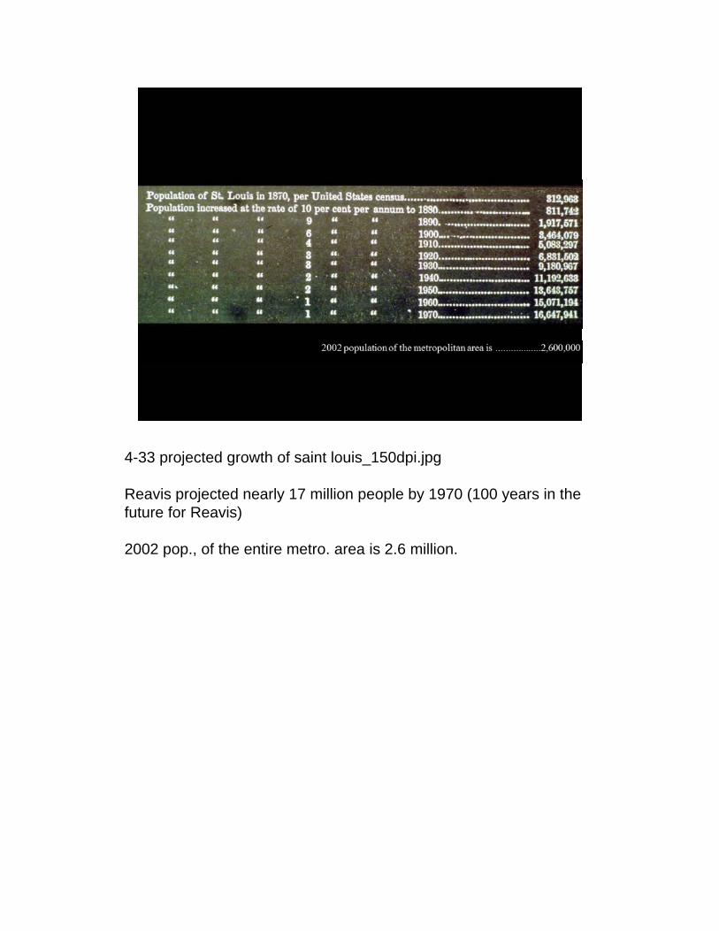
4-33 projected growth of saint louis_150dpi.jpg
Reavis projected nearly 17 million people by 1970 (100 years in the future for Reavis)
2002 pop., of the entire metro. area is 2.6 million.
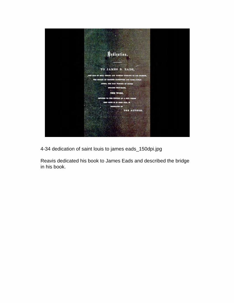
4-34 dedication of saint louis to james eads_150dpi.jpg
Reavis dedicated his book to James Eads and described the bridge in his book.

4-35 dedication of eads bridge by w_150dpi.jpg
Artist depiction of the July 4, 1874 dedication of the Eads Br. in St Louis. In this depiction we posit that apparently Eads old friends, and sometimes foes during construction, did not begrudge him his dedication and success.

4-36 eads bridge_150dpi.jpg xx cut
Replaced by 2004 picture from former student Tom Lydigsen (1/17/2004)The Eads Br. after its 2003 restoration

4-36 eads bridge_150dpi.jpg xx cut
Replaced by 2004 picture from former student Tom Lydigsen (1/17/2004)The Eads Br. after its 2003 restoration
walking on the bridge todayL pedestrian and car on top deck view of Missouri and StL -http://picasaweb.google.com/lh/photo/oYbUc59kCwVbHll4D7lNQAR state line - http://www.fouldsy.com/wp-content/2010/12/statelines.jpg

4-37 eads bridge lithograph by joseph pennell_150dpi.jpg
A favorite of artiss; here in lithograph by Joseph Pennell, the Eads Br. is a National Historic and Civil Engineering LandmarkUpon its completion in 1874 the Eads Br. was the longest spanning arch in the world at 520’
One surety about being the longest x in the world. It shall not last. Eiffel would span greater distances in steel arches in only a few years.
let us now turn to Eiffel again

Pause: turn to your partner and identify as many things as possible that are different between these two

4-39 garabit and douro viaducts_150dpi.jpg
Depicted in the slide is the 1877 Pia Maria, over the Douro in Portugal and the 1884 Garabit Viaduct. The Pia Maria following just 3 years after the Eads surpassed the Eads in central span, the Pia Maria was the model for Eiffel’s masterpiece the Garabit viaduct; which we shall study in some detail.
Contract for the Pia Maria was awarded in a competitive bid in which Eiffle was the lowest bidder by 31% over the next entrant. 6 of the 8 proposals used a central long span and were not remarkably dis-similar from Eiffel – but Eiiffel saved materials (steel) by shaping the arch to most efficiently carry the load and saved far greater amounts by pinning his arch at each end – thus the cantilever construction technique was greatly simplified at the point of arch completion as play was still available in the two arch halves before closing the gap – this construction simplification also simplifies the behavior and calculation. The only cost for such a move is a slight decrease in stiffness – but this was more than acceptable in this case.
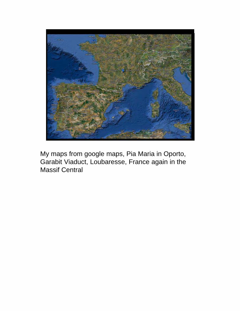
My maps from google maps, Pia Maria in Oporto, Garabit Viaduct, Loubaresse, France again in the Massif Central
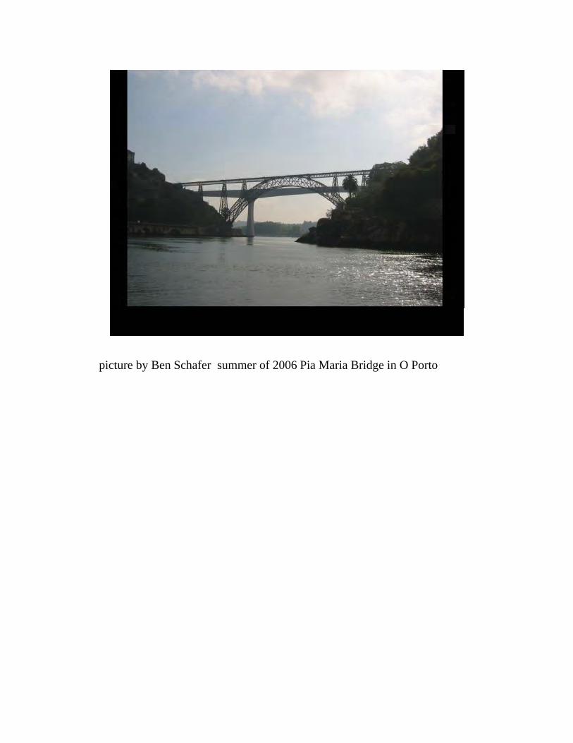
picture by Ben Schafer summer of 2006 Pia Maria Bridge in O Porto

4-38 garabit viaduct_150dpi.jpg
The 1884 Garabit viaduct did not go through a competitive bid –named as soul source b/c of low costs at Douro and Eiffel’s reputation.
Over the Truyere River near St. Flour France 165 m (540’) span
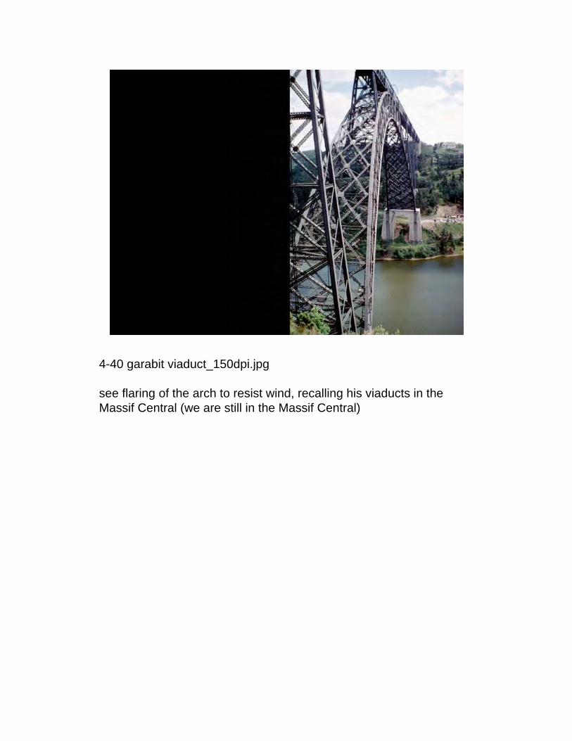
4-40 garabit viaduct_150dpi.jpg
see flaring of the arch to resist wind, recalling his viaducts in the Massif Central (we are still in the Massif Central)

4-41 garabit viaduct construction_150dpi.jpg
Construction used the innovations from the Pia Maria.

4-42 garabit viaduct construction_150dpi.jpg
The arches were cantilevered out, and connection was greatly eased (and cost) again due to the pinned bases.

4-43 eads bridge construction, stereopticon view_150dpi.jpg
recall Eads had fixed ends, Stiffer but harder to “close” in construction.

As Koblenz was the basis for EadsPia Maria was the basis for Garabit
Both of the second forms made a similar choice about the arch “deck” positioning. Aesthetic? Structural?
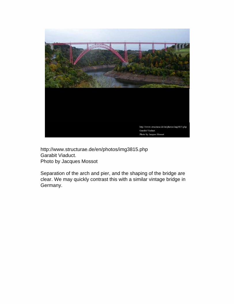
http://www.structurae.de/en/photos/img3815.phpGarabit Viaduct. Photo by Jacques Mossot
Separation of the arch and pier, and the shaping of the bridge are clear. We may quickly contrast this with a similar vintage bridge in Germany.

4-45 mungstener bridge_150dpi.jpg
Efficiency, economy, elegance. Elegance?

4-47 mungstener bridge_150dpi.jpg
confusion about tower and arch at springing


4-51 sign to garabit_150dpi.jpg
Now we move in on the Garabit for a closer look at details.
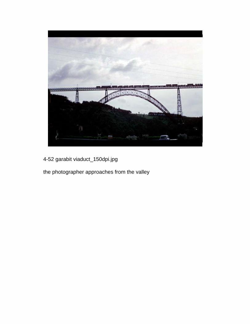
4-52 garabit viaduct_150dpi.jpg
the photographer approaches from the valley

4-53 garabit viaduct_150dpi.jpg
And we get our first look at the hinge detail at the abutments.

4-54 garabit viaduct_150dpi.jpg
sneaking around a bit of a door

4-55 garabit viaduct_150dpi.jpg
a closer look becomes available.
acension up the bridge to the left provides different persepctives on the Garabit.

4-56 garabit viaduct_150dpi.jpg
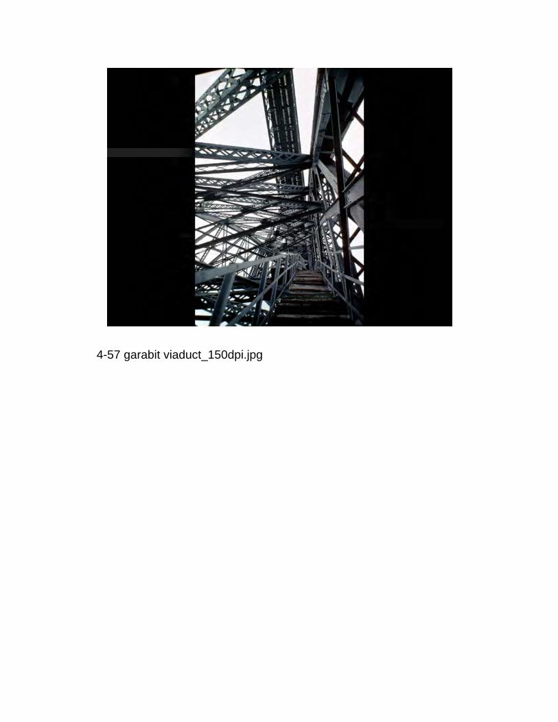
4-57 garabit viaduct_150dpi.jpg

4-58 garabit viaduct_150dpi.jpg

4-59 garabit viaduct_150dpi.jpg

4-60 garabit viaduct arch crown_150dpi.jpg
the arch just touches the railway above.

4-61 garabit viaduct_150dpi.jpg
the form is clear, the shaping of the supports is pronounced but perhaps not as refined as Rouzat or the Eiffel Tower, the visual and engineering focus is clearly on the 540’ main span crescent shaped arch.

4-79 garabit viaduct, the engineer's aesthetic_150dpi.jpg
Garabit has been an influential structure and served as the opening illustration in Le Corbusier’s chapter on the engineer’s aesthetic in his influential Towards a New Architecture.

4-62 garabit viaduct and truyere valley flooding_150dpi.jpg
The river was damned after completion.At the same time that all this fun with steel arches is going on in France and in the United States – Scotland was growing and building as well.
It is to Scotland where we turn for our next adventure in early “big steel” construction.


4-64 tay bridge failure_150dpi.jpg
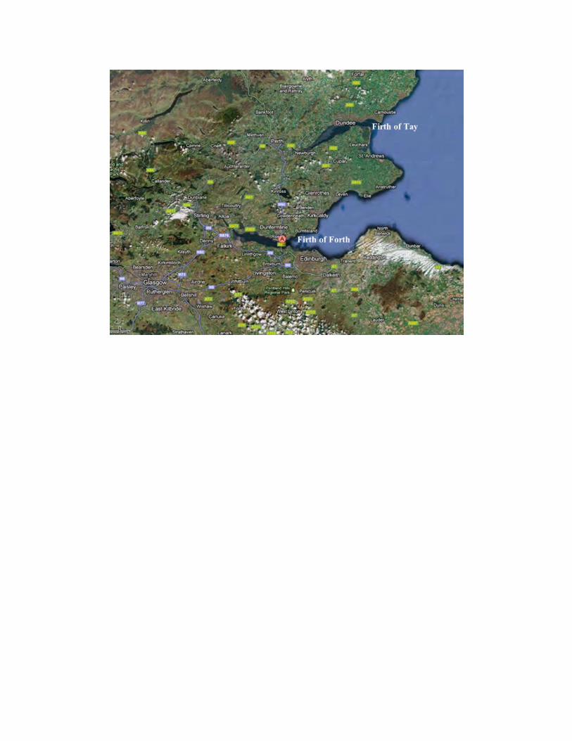
Between Christmas and New Year’s in 1879, 75 people perished as their train plummeted to the cold waters below. The failure shook the engineering world, destroyed the career of the structural engineer (Sir Thomas Bouch), who died just 1 year later. Further his plans for the world’s longest suspension bridge at the nearby Firth of Forth were also abandoned. The disaster is, perhaps, still regarded in the UK as a bit of a riddle but high winds, and a train load were definitively on the structure at the time of collapse.
Any comments on the form even from this one picture?


4-65 forth bridge_150dpi.jpg
The response to this failure was mammoth. The Firth of Forth RR bridge completed 10 years later by Baker and Fowler demonstrated and entirely different aesthetic and structural system. Here was a rigid RR bridge, the longest in the world, that was not to be trifled with. (Brunel’s 1864 Clifton susp. bri. was only 700+ ft., Brooklyn Br was 100’ less than Firth of Forth, the length increase - particularly for a RR br. with this design is profound – but so is that scale increase!)
Fowler one of the designers so distrusted the earlier 2 mile long Tay Br. that he had forbidden his family to go on it (Kirby et al, pg 312)
Not only the world’s longest, but stiff. Center deflection of 3 ½ in., under a train load = LL deflection of 3.5/(1710*12) = 1/5900(compare with modern ideals like 1/360 for example

4-66 forth bridge_150dpi.jpg
Appearing quite heavy from the foreshortened view. Each main span weighs 16,000 tons.330 ft. high towers, 120 ft. wide at bottom, 33’ wide at top

4-67 forth bridge_150dpi.jpg
Yet light from profile.

scanned from poetry book of same name.
Others have used the forth for inspiration, in their own way.

4-68 forth bridge structural system_150dpi.jpg
The designer Benjamin Baker used a simple model to demonstrate the principles of the cantilever bridge.
Benjamin Baker (1840-1907) wrote extensively about RR bridges and concluded that cantilever forms, due to their superior rigidity, were best for lengths over 700’. Use of suspension bridges for RR had met with some success; notably Roebling at Niagra, but required the trains to slow down – and were a bit lively.
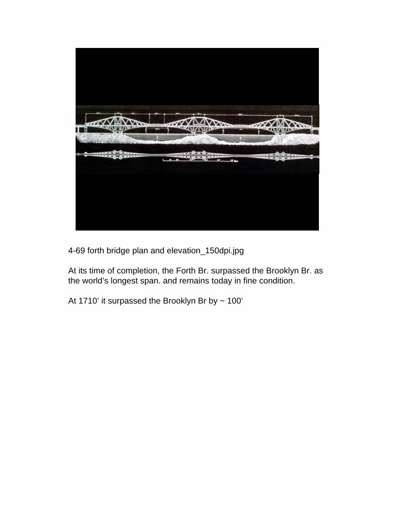
4-69 forth bridge plan and elevation_150dpi.jpg
At its time of completion, the Forth Br. surpassed the Brooklyn Br. as the world’s longest span. and remains today in fine condition.
At 1710’ it surpassed the Brooklyn Br by ~ 100’

4-70 forth bridge_150dpi.jpg

4-71 forth bridge_150dpi.jpg
The diagonals are quite pronounced and insures good stability under high winds.
Baker was serious about understanding the winds and he used scale models as well as gauges in the Firth itself. He found easterly gales of 15 to 20 psf, and westerlies of as high as 40 psf. He chose 56 psf as the design wind pressure.

4-72 forth bridge_150dpi.jpg
tension members are lattice worktubes are 1 1/4in. thick and as wide as 12’ in diameter.
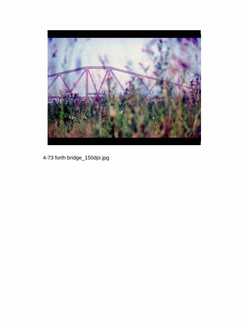
4-73 forth bridge_150dpi.jpg
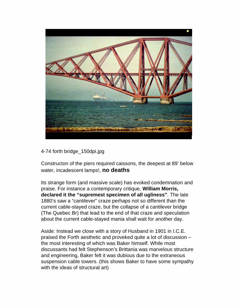
4-74 forth bridge_150dpi.jpg
Constructon of the piers required caissons, the deepest at 89’ below water, incadescent lamps!, no deaths
Its strange form (and massive scale) has evoked condemnation and praise. For instance a contemporary critique, William Morris, declared it the “supremest specimen of all ugliness”. The late 1880’s saw a “cantilever” craze perhaps not so different than the current cable-stayed craze, but the collapse of a cantilever bridge (The Quebec Br) that lead to the end of that craze and speculation about the current cable-stayed mania shall wait for another day.
Aside: Instead we close with a story of Husband in 1901 in I.C.E. praised the Forth aesthetic and proveked quite a lot of discussion –the most interesting of which was Baker himself. While most discussants had felt Stephenson’s Brittania was marvelous structure and engineering, Baker felt it was dubious due to the extraneous suspension cable towers. (this shows Baker to have some sympathy with the ideas of structural art)


2011 I was not able to squeeze this into lecture 3 and moved it, in part, to lecture 4


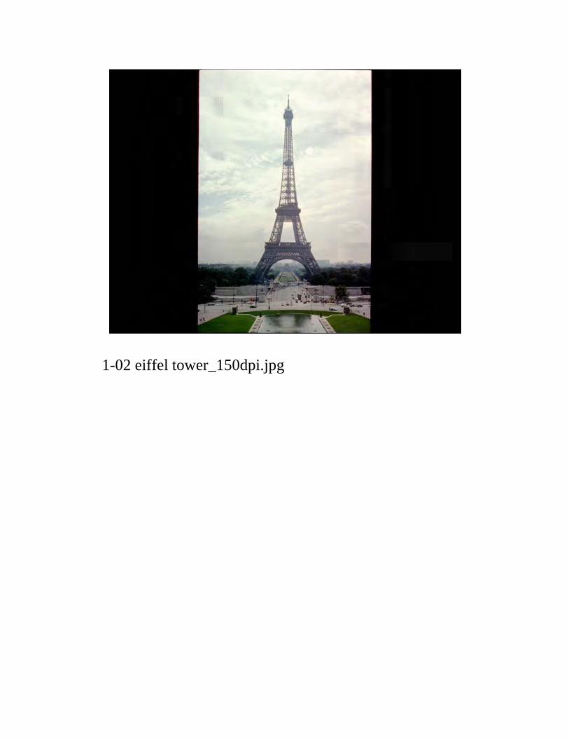
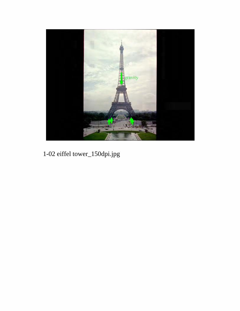
1-02 eiffel tower_150dpi.jpg
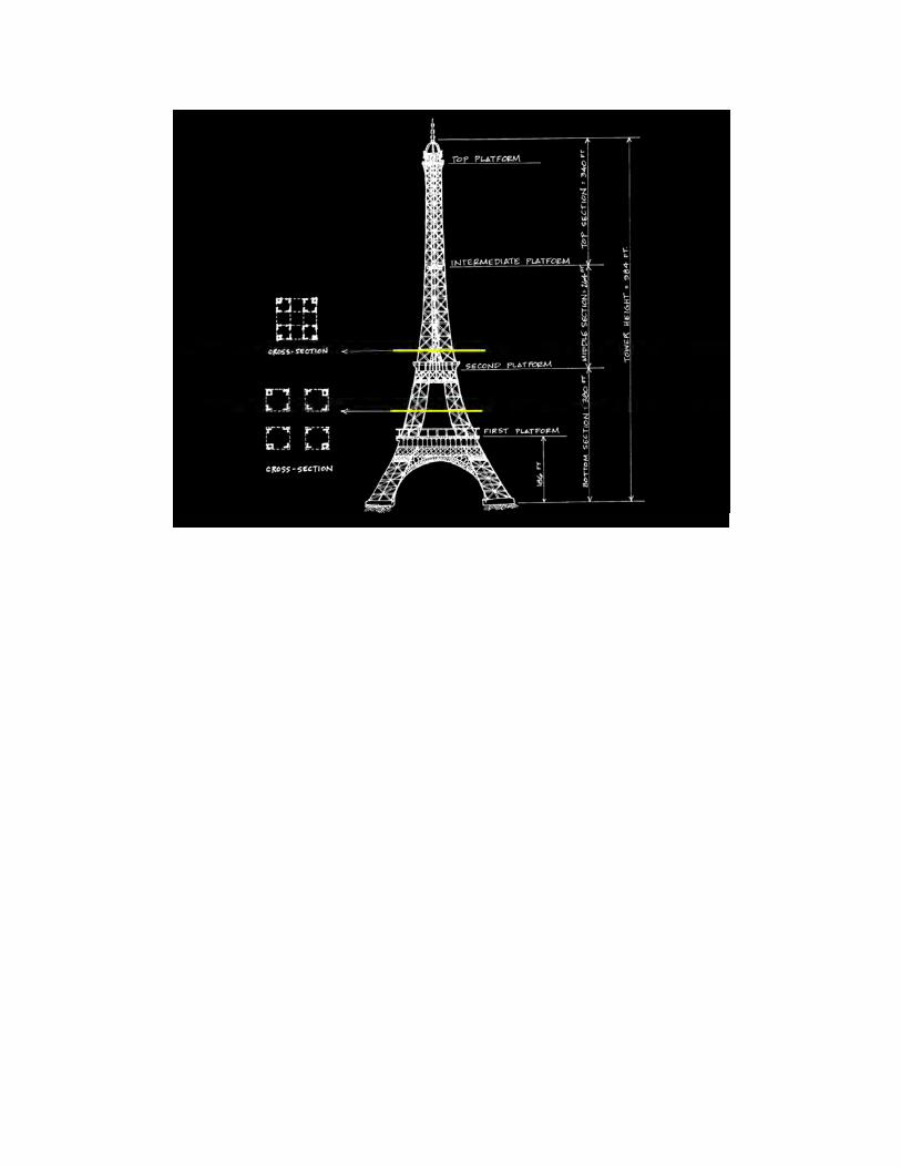
1-02 eiffel tower_150dpi.jpg

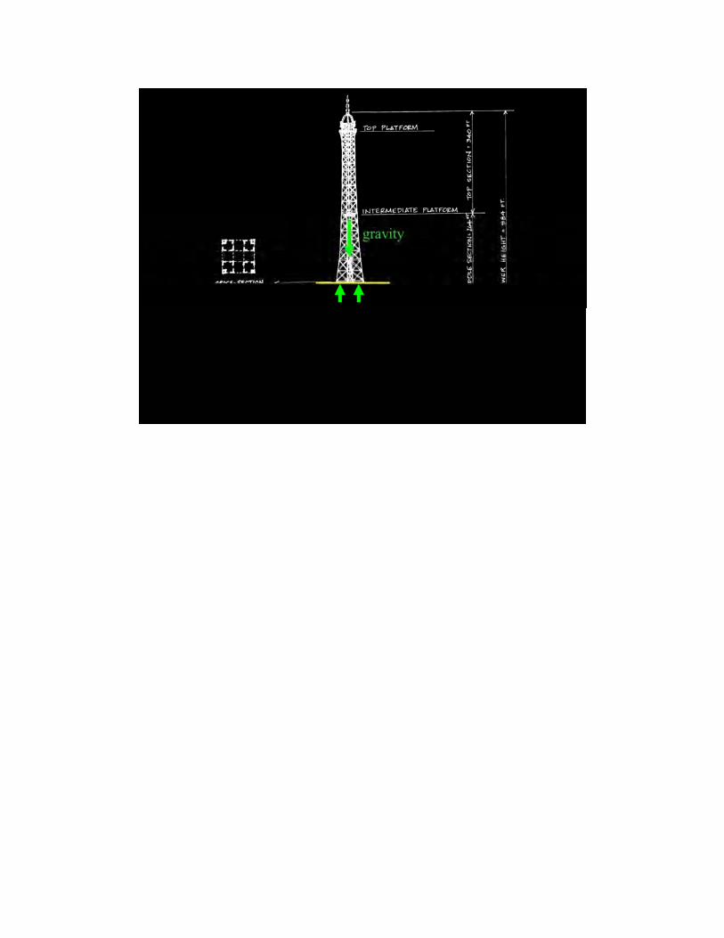
1-02 eiffel tower_150dpi.jpg

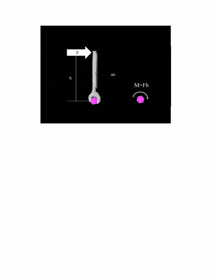
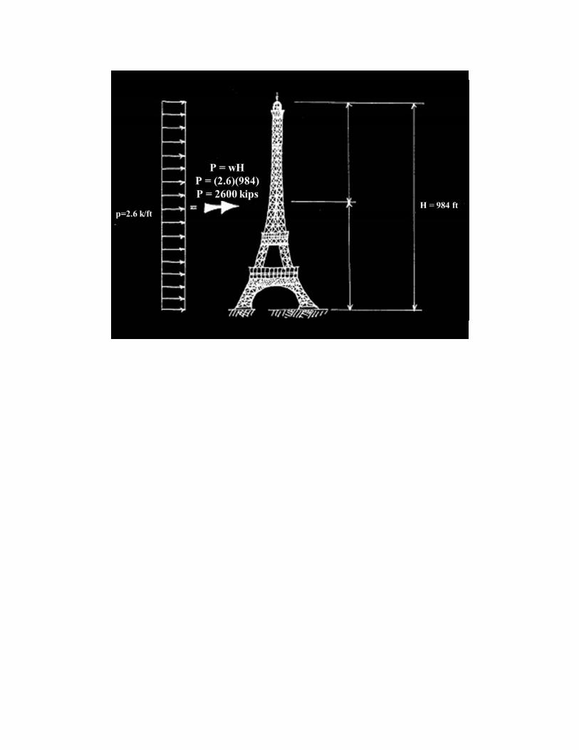

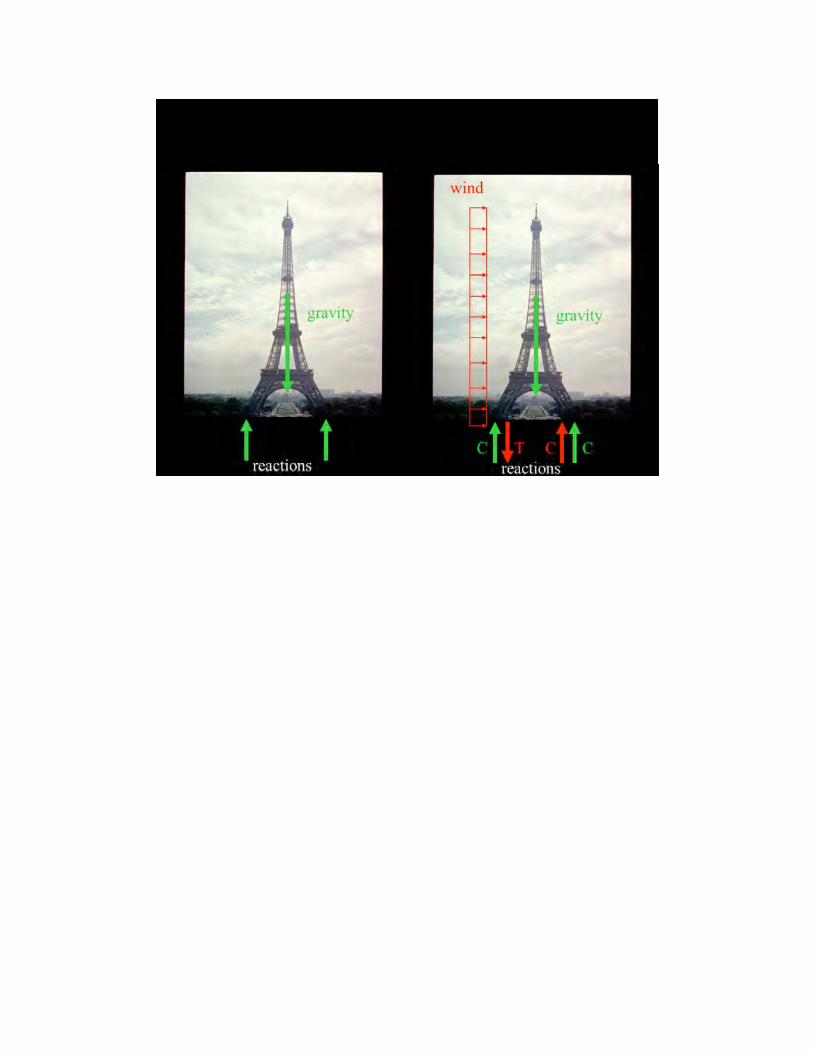
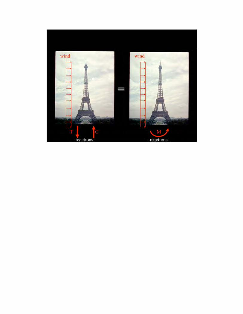

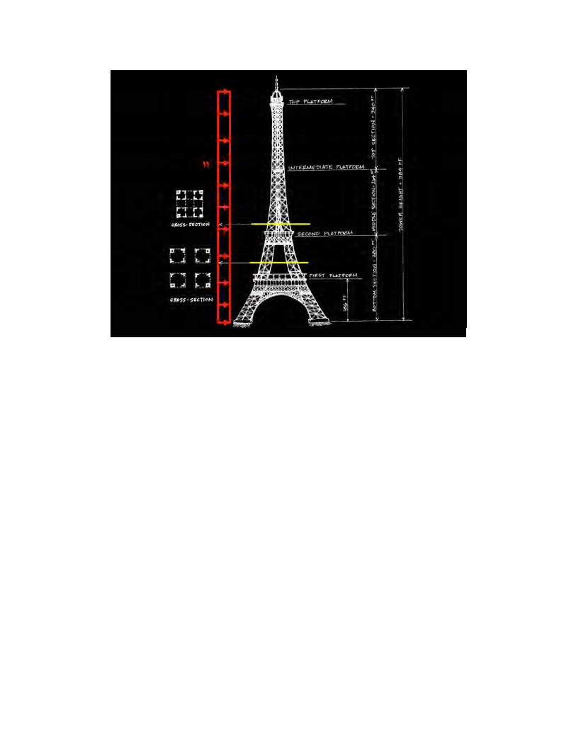


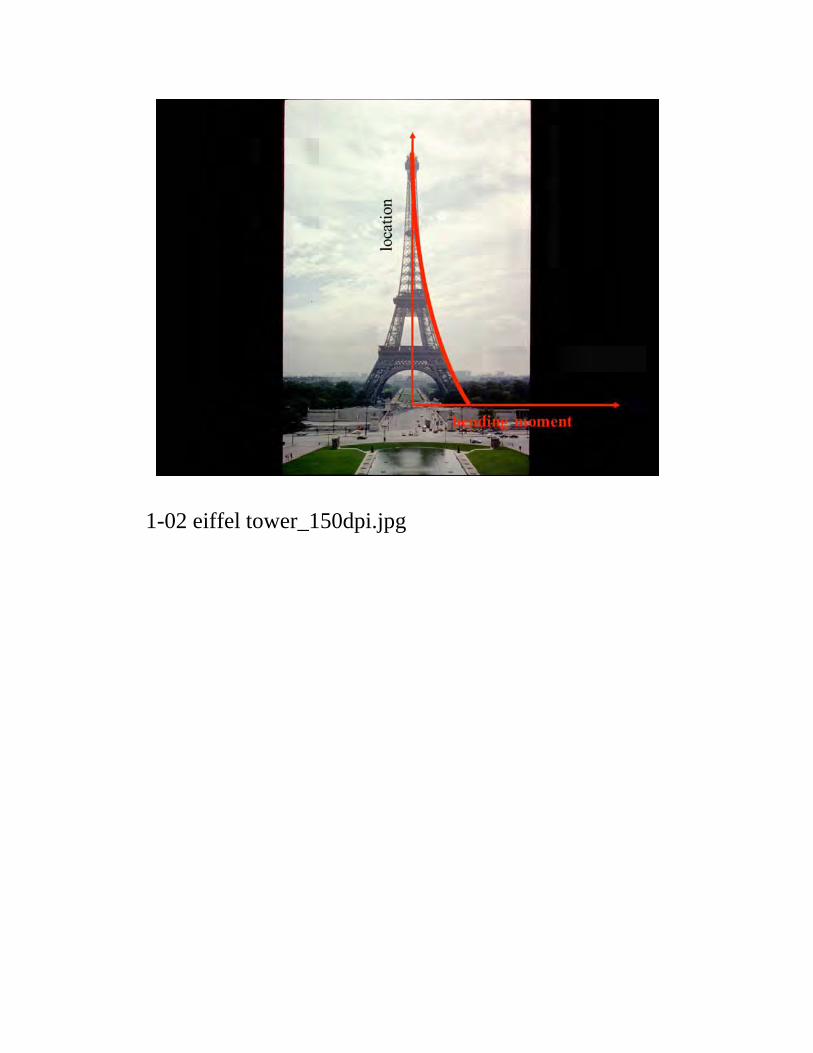
1-02 eiffel tower_150dpi.jpg


Of course the basic idea for a trussed arch returns us to Telford’s 1812 Bonar Bridge, or his 1814 Craigellachie Br., juxtaposed with Eads proposal
While Telford was the first to see the potential for iron in bridge design, Eads should be credited with being a very early adopter of steel.