
Belt conveyor system SGR | SPV – Operating instructions ...
38
4330053_A7 Operating Instructions Belt Conveyor System SGR | SPV
Transcript of Belt conveyor system SGR | SPV – Operating instructions ...

4330053_A7
Operating Instructions
Belt Conveyor System SGR | SPV

Section 1 Introduction Page 2 Appliance Information
Belt Conveyor System SGR | SPV 4330053_A7
1 Introduction
1.1 Appliance Information
Appliance name Belt Conveyor System
Appliance type/s SGR | SPV
Year of manufacture 2014
Manufacturer HUPFER® Metallwerke GmbH & Co KG Dieselstraße 20 48653 Coesfeld
Germany Postfach 1463 48634 Coesfeld, Germany
℡ +49 2541 80 50 6 +49 2541 805 111
www.hupfer.de [email protected]
Belt Conveyor System
SGR | SPV
Read and understand these operating instructions to ensure safe operation and avoid any damage! Ensure that operating staff have been briefed regarding sources of danger and possible incorrect handling.
Subject to modifications
The products covered by these operating instructions have been developed while taking into account market requirements and the latest technology. HUPFER® reserves the right to modify the products and related technical documentation in the interests of technical progress. The data and weights as well as the description of performance and functions assured in the order confirmation as binding are always decisive.
This manual is a translation of the original edition.
Manual edition 4330053_A7

Introduction Section 1 Table of Contents Page 3
Belt Conveyor System 4330053_A7 SGR | SPV
1.2 Table of Contents
1 Introduction 2 1.1 Appliance Information 2 1.2 Table of Contents 3 1.3 List of Abbreviations 5 1.4 Definitions of Terms 6 1.5 Orientation of the Appliance 7 1.6 Notes on Using the Manual 8 1.6.1 Notes on the Manual Structure 8 1.6.2 Notes and their Representation used in all Sections 8
2 Safety Instructions 9 2.1 Introduction 9 2.2 Symbols Used 9 2.3 Safety Instructions for Appliance Safety 10 2.3.1 Special Safety Instructions for Mobile Conveyor Systems 10 2.4 Position of the Emergency Stop Button 11 2.5 Safety Instructions for Transport and Installation 11 2.6 Safety Instructions for Use and Operation 11 2.7 Safety Instructions for Maintenance and Care 12 2.8 Safety Instructions Regarding Fault Repair 12 2.9 Notes on Specific Hazards 13
3 Description and Technical Data 14 3.1 Performance description 14 3.2 Proper Use 14 3.3 Improper Use 14 3.4 Appliance Description 15 3.4.1 View of the crockery return belt system 15 3.4.2 View of the food distribution belt system 16 3.4.3 Standard Equipment 16 3.4.4 Equipment and Optional Accessories 16 3.5 Technical data 18 3.6 Rating Plate 19
4 Transport, Installation, Initial Operation and Taking out of Service 20 4.1 Transport 20 4.2 Assembly 20 4.2.1 Assembly of segments 21 4.2.2 Pulling up the belt 22 4.2.3 Stretching the belt 22 4.2.4 Adjusting the belt 23 4.3 Commissioning 24 4.3.1 Connecting the conveyor system 24

Section 1 Introduction Page 4 Table of Contents
Belt Conveyor System SGR | SPV 4330053_A7
4.3.2 Measures for Putting the Appliance into Operation 25 4.4 Decommissioning, Storage and Recycling 25
5 Operation 27 5.1 Arrangement and Function of the Controls 27 5.2 Operation 28 5.3 Measures at the End of Use 28
6 Troubleshooting and Repair 29 6.1 Safety Measures 29 6.2 Instructions regarding Fault Repair 29 6.3 Fault and Action Table 29
7 Care and Maintenance 31 7.1 Safety Measures 31 7.2 Hygiene Measures 31 7.3 Notes on Care and Maintenance Measures 31 7.3.1 Table of care measures 32 7.3.2 Maintenance table 32 7.4 Special Care Instructions 33
8 Spare Parts and Accessories 34 8.1 Introduction 34 8.2 Spare Parts and Accessories List 34
9 Annex 35 9.1 Monthly Maintenance Checklist 35 9.2 Safety Instruction Protocol 36 9.3 EC Declaration of Conformity 37

Introduction Section 1 List of Abbreviations Page 5
Belt Conveyor System 4330053_A7 SGR | SPV
1.3 List of Abbreviations
Abbreviation Definition
CE Communauté Européene
European Community
DGUV German Statutory Accident Insurance (Deutsche Gesetzliche Unfallversicherung e.V.)
DIN German Institute for Standardisation, technical regulations and technical specifications
E/V Spare or wearing part (Ersatz- bzw. Verschleißteil)
EC European Community
European Community
EN European Standard (Europäische Norm)
Harmonised standard for the EU market
HACCP Hazard Analysis and Critical Control Points
Hazard analysis of critical control points
IP International Protection. The abbreviation IP and a further two-digit index specify the protection class of a housing. The first digit: Protection against ingress of solid foreign objects The second digit: Protection against ingress of water
0 No protection against contact, no protection against ingress of solid foreign bodies
0 No protection against ingress of water
1 Protection against contact with any large surface of the body such as the hand, protection against ingress of foreign objects ∅ > 1.97'' (50 mm)
1 Protection against dripping water (vertically falling drops)
2 Protection against contact with the fingers, protection against ingress of foreign objects ∅ > 0.5'' (12 mm)
2 Protection against dripping water (at any angle up to 15° from the vertical)
3 Protection against contact with tools, wires or similar objects of ∅ > 0.1'' (2.5 mm), protection against foreign objects ∅ > 0.1'' (2.5 mm)
3 Protection against water drips at any angle up to 60° from the vertical
4 Protection against contact with tools, wires or similar objects of ∅ > 0.04'' (1 mm), protection against foreign objects ∅ > 0.04'' (1 mm)
4 Protection against water splashing from any direction
5 Protection against contact, protection against dust deposits inside
5 Protection against water jets (projected by a nozzle) at any angle
6 Complete protection against contact, protection against ingress of dust
6 Protection against rough sea or strong water jets (flood protection)
7 Protection against ingress of water during temporary immersion
8 Protection against pressurised water during continuous immersion
LED Light Emitting Diode
Light diode
LMHV Regulation on the hygiene of foodstuffs
RCD Residual Current Device
Residual current device (RCD)
STB Safety temperature limiter
VDE Association of Electrical Engineering, Electronics and Information Technology (Verband der Elektrotechnik, Elektronik und Informationstechnik e.V.)
Section 1 Introduction Page 6 Definitions of Terms
Belt Conveyor System SGR | SPV 4330053_A7
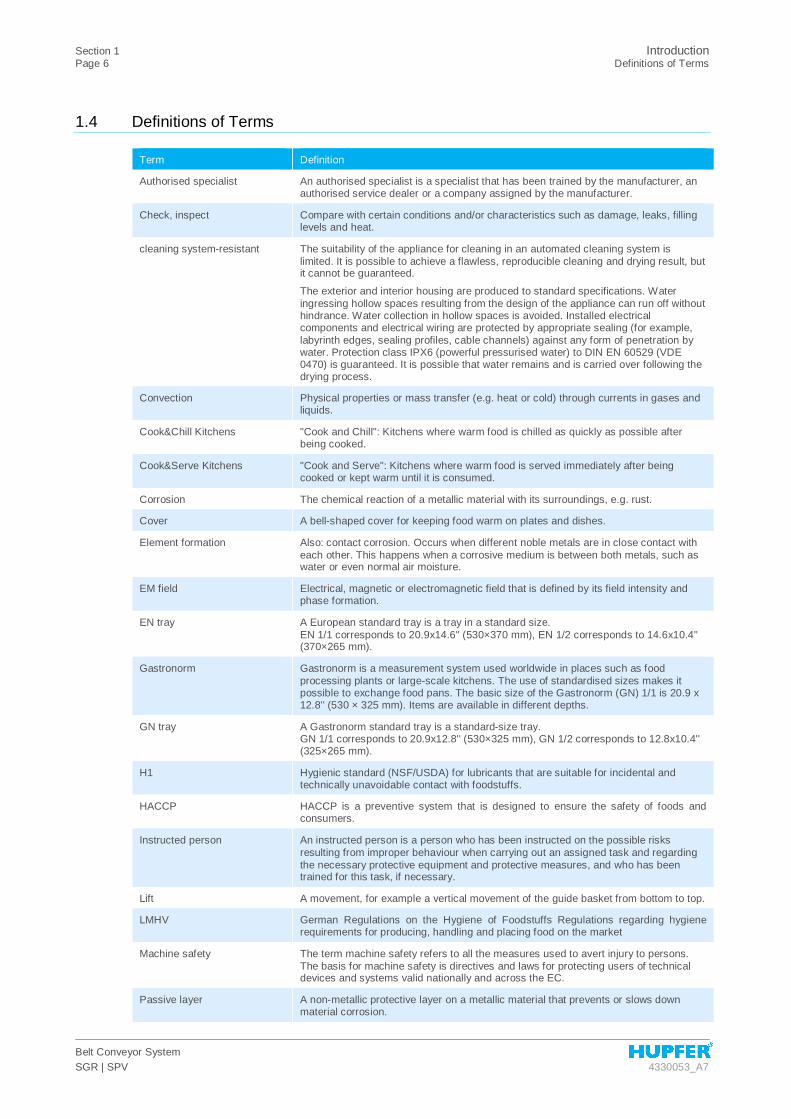
1.4 Definitions of Terms
Term Definition
Authorised specialist An authorised specialist is a specialist that has been trained by the manufacturer, an authorised service dealer or a company assigned by the manufacturer.
Check, inspect Compare with certain conditions and/or characteristics such as damage, leaks, filling levels and heat.
cleaning system-resistant The suitability of the appliance for cleaning in an automated cleaning system is limited. It is possible to achieve a flawless, reproducible cleaning and drying result, but it cannot be guaranteed.
The exterior and interior housing are produced to standard specifications. Water ingressing hollow spaces resulting from the design of the appliance can run off without hindrance. Water collection in hollow spaces is avoided. Installed electrical components and electrical wiring are protected by appropriate sealing (for example, labyrinth edges, sealing profiles, cable channels) against any form of penetration by water. Protection class IPX6 (powerful pressurised water) to DIN EN 60529 (VDE 0470) is guaranteed. It is possible that water remains and is carried over following the drying process.
Convection Physical properties or mass transfer (e.g. heat or cold) through currents in gases and liquids.
Cook&Chill Kitchens "Cook and Chill": Kitchens where warm food is chilled as quickly as possible after being cooked.
Cook&Serve Kitchens "Cook and Serve": Kitchens where warm food is served immediately after being cooked or kept warm until it is consumed.
Corrosion The chemical reaction of a metallic material with its surroundings, e.g. rust.
Cover A bell-shaped cover for keeping food warm on plates and dishes.
Element formation Also: contact corrosion. Occurs when different noble metals are in close contact with each other. This happens when a corrosive medium is between both metals, such as water or even normal air moisture.
EM field Electrical, magnetic or electromagnetic field that is defined by its field intensity and phase formation.
EN tray A European standard tray is a tray in a standard size. EN 1/1 corresponds to 20.9x14.6'' (530×370 mm), EN 1/2 corresponds to 14.6x10.4'' (370×265 mm).
Gastronorm Gastronorm is a measurement system used worldwide in places such as food processing plants or large-scale kitchens. The use of standardised sizes makes it possible to exchange food pans. The basic size of the Gastronorm (GN) 1/1 is 20.9 x 12.8'' (530 × 325 mm). Items are available in different depths.
GN tray A Gastronorm standard tray is a standard-size tray. GN 1/1 corresponds to 20.9x12.8'' (530×325 mm), GN 1/2 corresponds to 12.8x10.4'' (325×265 mm).
H1 Hygienic standard (NSF/USDA) for lubricants that are suitable for incidental and technically unavoidable contact with foodstuffs.
HACCP HACCP is a preventive system that is designed to ensure the safety of foods and consumers.
Instructed person An instructed person is a person who has been instructed on the possible risks resulting from improper behaviour when carrying out an assigned task and regarding the necessary protective equipment and protective measures, and who has been trained for this task, if necessary.
Lift A movement, for example a vertical movement of the guide basket from bottom to top.
LMHV German Regulations on the Hygiene of Foodstuffs Regulations regarding hygiene requirements for producing, handling and placing food on the market
Machine safety The term machine safety refers to all the measures used to avert injury to persons. The basis for machine safety is directives and laws for protecting users of technical devices and systems valid nationally and across the EC.
Passive layer A non-metallic protective layer on a metallic material that prevents or slows down material corrosion.

Introduction Section 1 Orientation of the Appliance Page 7
Belt Conveyor System 4330053_A7 SGR | SPV
Term Definition
Porcelain Standard Porcelain Standard is a measurement system for porcelain plates devised by HUPFER®. The basic size of Porcelain Standard (PN) 1/1 is 8.7 x 6.3'' (220x160 mm) (1/2 PN conforms to 4.3x6.3'' (110x160 mm), 1/4 PN conforms to 6.3x3.1'' (160x80 mm)). The fitting lids have the following dimensions: 1/1 PN 9x6.6'' (228x168mm), 1/2 PN 4.4x6.3'' (111x161mm), 1/4 PN 4.4x3.2'' (111x81mm).
Protection class 0 ¯
I
II
III
Qualified person, qualified personnel
Qualified personnel are persons who due to their professional training, experience, instruction and their knowledge of relevant standards, guidelines, accident prevention regulations and operating conditions have been authorised by a person responsible for system safety to carry out required activities and can recognise and prevent any potential hazards (definition of specialists according to IEC 364).
Schuko® The abbreviation of the German term "Protective contact" indicates a system of domestic plugs and sockets equipped with protective earthed contacts used in most of Europe.
Specialist A specialist is a person who can assess work assigned and can recognise possible hazards themselves based on their professional training, skills, experience and knowledge of the respective guidelines.
suitable for washing devices The appliance is suitable for cleaning in an automated cleaning system without restrictions. Following agreement with the manufacturer the cleaning system must achieve a hygienic, constant cleaning and drying result, which is to be approved by a third party (client).
The exterior and interior housing are manufactured to a standard guaranteeing hermetic sealing. It is not possible for water jets to ingress into hollow spaces in the appliance. Installed electrical components and electrical wiring are protected by appropriate sealing against any form of penetration by water. Protection class IPX6 (powerful pressurised water) to DIN EN 60529 (VDE 0470) is guaranteed. No water remains or is carried over following the drying process.
Verify, test Compare with certain values such as weight, torque, content or temperature.
VESKA standard Trays as per the VESKA standard are items used for distributing food in hospitals, principally in Switzerland; they measure 20.9x14.8" (530x375 mm)
1.5 Orientation of the Appliance
The front
"Front" refers to the side where members of the staff place trays (beginning of the belt).
The rear
"Rear" refers to the side where trays are taken from the belt. The controls of the conveyor system are fitted here (end of the belt).
The right
"Right" refers to the right side of the conveyor system in relation to the conveying direction.
The left
"Left" refers to the left side of the conveyor system in relation to the conveying direction.

Section 1 Introduction Page 8 Notes on Using the Manual
Belt Conveyor System SGR | SPV 4330053_A7
1.6 Notes on Using the Manual
1.6.1 Notes on the Manual Structure
This manual is divided into function- and task-focused sections.
1.6.2 Notes and their Representation used in all Sections
The warnings and notes are separated from the other text and particularly marked by corresponding icons. The icon cannot, however, replace the text of the safety instructions. Therefore, always read thoroughly the full text of the safety instructions. The warnings and notes are separated in these operating instructions as follows and categorised by the following danger levels by means of various symbols.
DANGER Brief description of hazard
There is an imminent threat to life and physical well-being for the user and / or third parties if instructions are not followed precisely or the circumstances described are not taken into account. The type of hazard is indicated by a symbol and explained in the accompanying text in more detail. The general hazard symbol is used in this example.
WARNING Brief description of hazard
There is an indirect threat to life and physical well-being for the user and / or third parties if the instructions are not followed precisely or the circumstances described are not taken into account. The type of hazard is indicated by a symbol and explained in the accompanying text in more detail. The general hazard symbol is used in this example.
CAUTION Brief description of hazard
There is a potential risk of injury or property damage if the instructions are not followed precisely or the circumstances described are not taken into account. The type of hazard is indicated by a general symbol and explained in the accompanying text in more detail. The general hazard symbol is used in this example.
NOTE Brief description of additional information Attention is pointed to special conditions or additional important information on
the topic concerned.
INFO Short title It contains additional information on work ease or recommendations on the
topic concerned.
Safety Instructions Section 2 Introduction Page 9
Belt Conveyor System 4330053_A7 SGR | SPV
2 Safety Instructions
2.1 Introduction
The Safety Instructions section describes the risks associated with the appliance in terms of product liability (according to the EU Machinery Directive).
The safety instructions are meant to warn of hazards and help to avoid damage to persons, the environment and property. Please make sure that you have read and understood all the safety instructions given in this section.
The valid national and international Safety at Work Regulations must be complied with. The manufacturer is responsible for the valid regulations he/she has to provide. He/she must acquaint himself/herself and the operator with the new regulations.
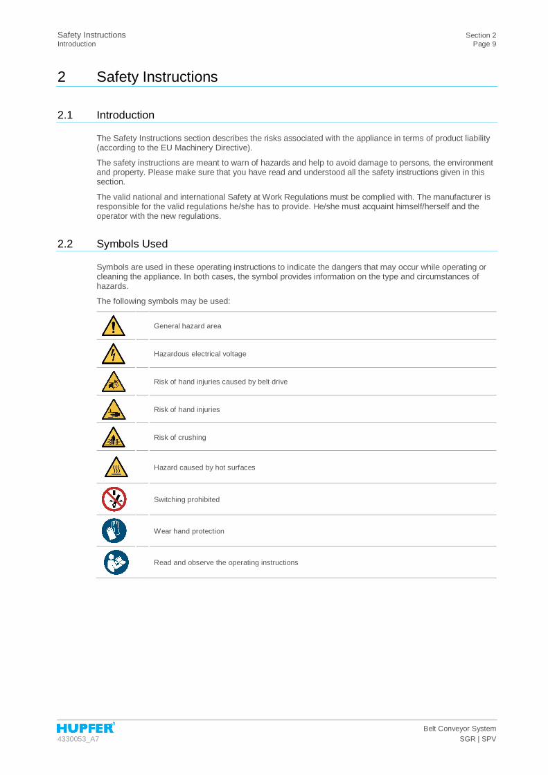
2.2 Symbols Used
Symbols are used in these operating instructions to indicate the dangers that may occur while operating or cleaning the appliance. In both cases, the symbol provides information on the type and circumstances of hazards.
The following symbols may be used:
General hazard area
Hazardous electrical voltage
Risk of hand injuries caused by belt drive
Risk of hand injuries
Risk of crushing
Hazard caused by hot surfaces
Switching prohibited
Wear hand protection
Read and observe the operating instructions

Section 2 Safety Instructions Page 10 Safety Instructions for Appliance Safety
Belt Conveyor System SGR | SPV 4330053_A7
2.3 Safety Instructions for Appliance Safety
The appliance is operated safely if it is used correctly and carefully. Negligent handling of the appliance can lead to a threat to life and physical well-being for the user and / or third parties as well as hazards for the appliance itself and the operator's other property.
The following points are to be observed to ensure the appliance safety:
§ The appliance may only be operated as intended, when it is in perfect condition with regards to technical standards, with awareness of safety and hazards and in accordance with the operating instructions.
§ All operating and actuating elements must be in a perfect and fail-safe condition with regards to technical standards.
§ Only operate the conveyor system when all safety devices or emergency stop devices are available and function properly. Easy access to the emergency stop button needs to be ensured. Never remove safety devices.
§ Comply with the safety instructions and hazard warnings on the conveyor system and make sure they are easy-to-read.
§ Before putting the appliance into operation, the appliance must be checked for external visible damage and defects. In case of damage, immediately inform the competent bodies and switch off the conveyor system.
§ Modifications or retrofits to the equipment are only permitted after consultation with the manufacturer and upon receipt of their consent in writing.
§ Stationary conveyor systems are designed for permanent installation.
2.3.1 Special Safety Instructions for Mobile Conveyor Systems
§ The conveyor systems are designed for transport by hand only. It is not permitted to use a machine of any type to move the appliance.
§ Conveyor systems can start moving on their own and randomly if the total locks are not applied.
§ Switch off the conveyor system and pull out the mains plug before transporting it.
§ Never pull the mains plug out of the socket by the wire.
§ Before moving the conveyor system, release the locking brakes. Moving the appliance with the applied locking brakes can damage the chassis!
§ Do not move the appliance over inclined surfaces or stairs. When approaching walls and moving round obstacles always pay attention to persons in the way.
§ When transporting the conveyor system, do not move it faster than a walking pace. It is difficult to brake and steer heavily laden appliances. If necessary, ask for assistance when transporting the appliance.
§ When moving the conveyor system, make sure that the appliance will not tip over due to outside influences or inattention. If, nevertheless, it tips over never try to catch the conveyor system.
§ Secure the conveyor system against rolling away by applying the total locks before putting it into operation.
§ Do not place the appliance on sloping floors. Before placing the appliance in position make sure that the floors are level and even and the conveyor system is level.
§ A maximum belt length of 7 m may not be exceeded.

Safety Instructions Section 2 Position of the Emergency Stop Button Page 11
Belt Conveyor System 4330053_A7 SGR | SPV
2.4 Position of the Emergency Stop Button
Figure 1 Position of the Emergency Stop button (option)
2.5 Safety Instructions for Transport and Installation
The following aspects are to be taken into account when transporting the conveyor system:
§ When loading, use only hoists and load lifting devices approved for appliances 1,5 times heavier than the appliance to be lifted.
§ Only use transport vehicles that are approved to carry the weight of the conveyor system.
§ Use transport vehicles that are approved for the weight of the conveyor system.
§ Parts that have possibly been dismantled for transport must be fitted back and fastened before putting the appliance into operation again.
§ Even in case of a minor relocation switch off the conveyor system at the mains or disconnect it from any power supply.
§ In accordance with the legal regulations the buyer bears the risk of transportation. Ask the deliverer to write down visible damages in the waybill.
§ Do not put a defective appliance into operation under any circumstances and inform the supplier immediately in such a case.
2.6 Safety Instructions for Use and Operation
The following points shall be observed when using and operating the appliance:
§ Staff is to be instructed in the use and operation of the conveyor system before it is started.
§ Loose items of clothing (e.g. scarf or tie) and jewellery are not to be worn when working on the conveyor system. Otherwise there is the risk of being pulling in by rotating machinery parts.
§ Unimpeded access to the Emergency Stop buttons must be on hand at all times.
§ Make sure that nobody is exposed to a hazard as a result of the activation of the conveyor system before switching on the appliance.

Section 2 Safety Instructions Page 12 Safety Instructions for Maintenance and Care
Belt Conveyor System SGR | SPV 4330053_A7
2.7 Safety Instructions for Maintenance and Care
The following points shall be observed when carrying out any maintenance operations:
§ Take the conveyor system out of operation, switch it off and secure against unauthorised reactivation before performing maintenance or troubleshooting operations. The appliance must be switched off at the mains and secured against reactivation when working on the electrical system.
§ Only persons with qualifications and knowledge of electrical engineering may perform maintenance and repair work on electrical devices.
§ If maintenance or repair work at live parts is required, a second person must be involved at all times.
§ The maintenance and care intervals specified in the operating instructions must be observed.
§ Before proceeding with maintenance and repair work close the maintenance area and the access to the working area for unauthorised persons. If necessary, place an indication sign that draws attention to the running maintenance and repair work.
§ Observe the valid product safety regulations for the product when handling oils, greases and other chemical substances.
§ Lubricants must be compatible with foodstuffs such as edible oil.
§ Carry out all the checks and inspections of the appliance on a regular basis. Remove immediately deficiencies, such as loose screw connections or melted cables.
§ Fit the dismantled safety devices back to the appliance and check them for proper functionality after completing maintenance and repair work.
§ Cleaning instructions must be strictly observed for reasons of hygiene.
§ Never clean the running conveyor system.
§ Do not clean the conveyor system with steam-jet or high-pressure cleaners.
§ Take the conveyor system out of operation and switch it off at the mains in any area where steam-jet or high-pressure cleaners are to be used.
2.8 Safety Instructions Regarding Fault Repair
The following aspects must be taken into account when carrying out any troubleshooting work:
§ The local Accident Prevention Regulations in force must be observed.
§ Take the conveyor system out of operation, switch it off and secure against unauthorised reactivation before performing maintenance or troubleshooting operations. The appliance must be switched off at the mains and secured against reactivation when working on the electrical system.
§ Observe the valid product safety regulations for the product when handling oils, greases and other chemical substances.
§ Wear suitable protective clothing when carrying out any repair work.
§ Only authorised specialists may repair any faults or malfunctions.
§ Tighten the loosened screw connections and fit the safety devices back to the appliance if dismantled, and test their proper functioning after completing the repair work.
§ Defective components may be replaced with original parts only.

Safety Instructions Section 2 Notes on Specific Hazards Page 13
Belt Conveyor System 4330053_A7 SGR | SPV
2.9 Notes on Specific Hazards
Electric power
§ All work on the electrical installations may only be carried out by a qualified electrician or by authorised specialists under the supervision and monitoring of a qualified electrician according to the applicable electro-technical regulations.
§ The appliances on which inspection, maintenance and fault repairs are performed must be disconnected from the power supply and secured against reactivation when power is not required for such work. This may only be carried out by a qualified electrician.

Section 3 Description and Technical Data Page 14 Performance description
Belt Conveyor System SGR | SPV 4330053_A7
3 Description and Technical Data
3.1 Performance description
The conveyor system is designed to transport trays loaded with crockery. The conveyor system conveys the trays to the following work step. Depending on the type used, the conveyor system conveys either clean trays loaded with portioned meals or trays containing dirty crockery.
The crockery return belt system (SGR) is used mainly to hold up Gastronorm and Euronorm trays and to clear away continuously and quickly trays with dirty crockery, cutlery, glasses and napkins. Members of the operating staff clear away the trays loaded with dirty crockery items that are conveyed to the washing area.
The food distribution belt system (SPV) is used mainly to hold up Gastronorm and Euronorm trays and to load continuously and quickly trays with portioned meals, crockery, cutlery, glasses and napkins. Serving devices and operating staff that stays at the conveyor system load trays and serve portions on crockery items. To serve meals up to the guest area, other peripheral devices at the end of the belt can be used.
Thanks to the modular design and the wide number of standard components, the conveyor system can be perfectly suited to any premises. Peripheral appliances and optional accessories can be added in order to substantially streamline operations. Components suitable for use with foodstuffs and easy-to-clean construction ensure the highest hygienic standard.
3.2 Proper Use
The conveyor system is mainly designed to hold up Gastronorm and Euronorm trays. Any other use is not permitted.
The crockery return belt system (SGR) is used to hold up and to convey away trays with dirty crockery, cutlery, glasses and napkins.
The food distribution belt system (SPV) is used to hold up and to convey away trays with portioned meals, clean crockery, cutlery, glasses and napkins.
Proper use includes observing specified procedures, compliance with the technical specifications and use of supplied or optional original accessories.
Any other use of the appliance is considered as unintended use.
3.3 Improper Use
Any other use, especially loading the conveyor system with the other loads than those specified, is not permitted.
In particular, transport of materials hazardous to foodstuffs is considered as unintended use.
Do not transport heavy and sharp-edged items on the conveyor system. It is not permitted to convey stacked crockery items.
Do not allow people to sit or store objects on the conveyor system. Transport of people is not permitted.
It is not permitted to modify or retrofit the conveyor system. Such modifications can pose safety hazard and are considered as unintended.
The manufacturer and suppliers are not liable for any consequential damage resulting from unintended use. No liability is assumed and no warranty claims can be submitted for damages caused by improper use.

Description and Technical Data Section 3 Appliance Description Page 15
Belt Conveyor System 4330053_A7 SGR | SPV
3.4 Appliance Description
3.4.1 View of the crockery return belt system
Figure 2 View of the appliance SGR 1 Beginning of the belt 2 Connector with conveyor roller 3 Belt 4 Control 5 Belt system leg 6 Cleaning drawer with scraper 7 Control panel 8 End of the belt 9 Limit switch 10 Light barrier 11 Drive component with drive station 12 Intermediate part 13 Conveying direction 14 Deflection element

Section 3 Description and Technical Data Page 16 Appliance Description
Belt Conveyor System SGR | SPV 4330053_A7
3.4.2 View of the food distribution belt system
Figure 3 View of the appliance SPV 1 Beginning of the belt 2 Connector with conveyor roller 3 Belt 4 Control 5 Belt system leg 6 Cleaning drawer with scraper 7 Control panel 8 End of the belt 9 Limit switch 10 Drive component with drive station 11 Intermediate part 12 Conveying direction 13 Deflection element
3.4.3 Standard Equipment
The standard design of the conveyor system includes a dirt scraper and a cleaning drawer that are fitted at the end of the belt underneath the controls.
The dirt scraper is necessary to clean the belt regularly. It is fitted in such a way that the distance between the belt and dirt scraper is sufficient to remove leftovers and impurities form the belt without damaging it. Leftovers and impurities wiped off by the scrapper fall down into the cleaning drawer.
3.4.4 Equipment and Optional Accessories
You can install and fit the conveyor system with optional accessories in various ways:
§ Types of installation (SGR and SPV): The standing alone design of the conveyor system is mounted on stand feet. A combination of wall and base installation is possible. A mobile design includes 2 swivel casters per belt system leg. All swivel casters consist of total locks for safety reason.
§ Plastic shelves in the base (SGR and SPV) The plastic shelves are designed as storage shelves in the base. The elements are placed on the long rails in the base of the conveyor system. The shelves are suitable for long-term use, even at maximum load (up to 10 kg/m) at temperatures between -30°C and +70°C.

Description and Technical Data Section 3 Appliance Description Page 17
Belt Conveyor System 4330053_A7 SGR | SPV
§ End segment with limit rocker switch (SGR and SPV) The limit rocker switch is fitted in the end segment of the frame surface at the end of the belt. In case of mechanical strain the limit rocker switch will be pressed down, thus generating an electric signal, and the belt will stop moving. After releasing the limit rocker switch the belt will start moving automatically. The switch mechanism is protected on all sides against ingress of liquids and dirt particles.
§ Light barrier (SGR and SPV) The light barrier prevents the further movement of trays beyond the end of the belt; depending on the setting, with or without crockery items. The light barrier is fitted on the end of the belt as a height restriction (crockery detector) inserted along with the reflector into covers made of stainless steel. They are fastened facing each other and flush on the bar of the edge of the well. Adjust the optic sensors after consultation; the minimum height is approx 0.2'' (5 mm) below the edge, the maximum heigh is approx. 0.8'' (20 mm) above the edge. Place the light barrier at the middle, about 13.8'' (350 mm) from the end of the belt.
§ Foot switch (SPV only) The foot switch allows to start and stop the conveyor belt. It is used in addition to the operating elements on the control panel.
§ Patient card drawer (SPV only) The patient card drawer holds up patient cards and can be removed quickly and completely without any tools. It is fitted under the conveyor belt at the beginning of the belt system. The maximum load of 25 kg may not be exceeded.
§ Rotary table (SPV only) Use the rotary table that is fitted at the beginning of the belt at about 9.8" (250 mm) from the front side to keep your records or other information. The rotary table and the support tube rotate independently of each other. The rotary table may only be moved when there are no objects on its surface and there are no people around it. The maximum load of about 5 kg may not be exceeded. The rotary table is delivered disassembled. To assemble the rotary table, insert the support tube into the plastic part.
§ Hinged board (SPV only) The hinged board is an additional storing shelf and is fitted flush at the end of the belt. The board can be folded up by lifting it slightly up and raising it to an angle of 90°. It is not permitted to locate any objects on the board when folding it down. The maximum load of about 10 kg may not be exceeded in order not to risk any material damage.
§ Sorting bridges (SGR only) The sorting bridge is used for safe storage on the opposite belt casing. The sorting bridge can be folded by lifting it lightly up and raising it to an angle of 90°. The unfolded sorting bridge is flush with the belt casing. The hinged design without a chute but with a sound absorbing panel attached at the bottom can be fitted on the belt upon agreement. The maximum load of the sorting bridge is 25 kg.
Section 3 Description and Technical Data Page 18 Technical data
Belt Conveyor System SGR | SPV 4330053_A7
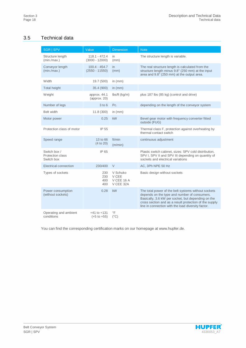
3.5 Technical data
SGR | SPV Value Dimension Note
Structure length (min./max.)
118.1 - 472.4 (3000 - 12000)
in (mm)
The structure length is variable.
Conveyor length (min./max.)
100.4 - 454.7 (2550 - 11550)
in (mm)
The real structure length is calculated from the structure length minus 9.8'' (250 mm) at the input area and 9.8'' (250 mm) at the output area.
Width 19.7 (500) in (mm)
Total height 35.4 (900) in (mm)
Weight approx. 44.1 (approx. 20)
lbs/ft (kg/m) plus 187 lbs (85 kg) (control and drive)
Number of legs 3 to 6 Pc. depending on the length of the conveyor system
Belt width 11.8 (300) in (mm)
Motor power 0.25 kW Bevel gear motor with frequency converter fitted outside (FUG)
Protection class of motor IP 55 Thermal class F, protection against overheating by thermal contact switch
Speed range 13 to 66 (4 to 20)
ft/min (m/min)
continuous adjustment
Switch box / Protection class Switch box
IP 65 Plastic switch cabinet, sizes: SPV cold distribution, SPV I, SPV II and SPV III depending on quantity of sockets and electrical variations
Electrical connection 230/400 V AC, 3Ph NPE 50 Hz
Types of sockets 230 230 400 400
V Schuko V CEE V CEE 16 A V CEE 32A
Basic design without sockets
Power consumption (without sockets)
0.28 kW The total power of the belt systems without sockets depends on the type and number of consumers. Basically, 3.6 kW per socket, but depending on the cross section and as a result protection of the supply line in connection with the load diversity factor.
Operating and ambient conditions
+41 to +131 (+5 to +55)
°F (°C)
You can find the corresponding certification marks on our homepage at www.hupfer.de.

Description and Technical Data Section 3 Rating Plate Page 19
Belt Conveyor System 4330053_A7 SGR | SPV
3.6 Rating Plate
The rating plate of the conveyor system is fitted on the inner side of the door of the switch cabinet.
Figure 4 Rating plate 1 Disposal of old appliances 9 Nominal current 2 Certification mark 10 Frequency 3 Protection class 11 Nominal voltage 4 Refrigeration capacity 12 Payload 5 Refrigerant 13 Tare weight 6 Induction frequency 14 Serial number/Order number 7 Electrical serial number 15 Item and brief description 8 Electric power 16 Manufacturer

Section 4 Transport, Installation, Initial Operation and Taking out of Service Page 20 Transport
Belt Conveyor System SGR | SPV 4330053_A7
4 Transport, Installation, Initial Operation and Taking out of Service
4.1 Transport
The delivered conveyor system with a length of up to 6 m is completely assembled, wired and set so that it is ready for operation. Conveyor systems with a length of more than 6 m will be delivered segments that have to be assembled.
When loading, use only hoists and load lifting devices approved for appliances 1.5 times heavier than the conveyor system to be lifted. Only transport vehicles that are approved for the weight of the appliance may be used.
The scope of delivery is specified in the shipping documents in accordance with the valid purchase agreement and included with the delivery item.
4.2 Assembly
DANGER Hazardous electrical voltage
Electrical current can pose a considerable threat to life and physical well-being and may lead to injuries. Only an electrician or instructed staff under the guidance and supervision of an electrician may work on electrical systems or operational equipment; they must comply with the electrical industry rules while doing so.
DANGER Defective emergency stop
In case of fault, e.g. from defective fuses, the drives may continue to run even after the emergency stop has been pressed.
CAUTION Rotating machine parts
There is an indirect risk of injuries of the fingers caused by being pulled into the appliance and crushing. Avoid any direct contact with the running conveyor belt and the outlet, feeding and deflection points during assembly or when performing any other work. Never reach into the hazardous area of the conveyor system. Before switching on the conveyor system, make sure there is no risk of reactivation of the belt.
CAUTION Injury to persons
The segments and the conveyor belt may only be assembled by two persons. Wear protective goggles and safety gloves at all times when placing and joining the belt.
INFO Conveyor systems longer than 6 m The following section only applies to conveyor systems longer than 6 m which
need not be delivered and mounted as a unit.
Transport, Installation, Initial Operation and Taking out of Service Section 4 Assembly Page 21
Belt Conveyor System 4330053_A7 SGR | SPV
4.2.1 Assembly of segments
CAUTION Injury to persons and/or damage to property
There is a risk that parts of the conveyor system fall down during the assembly. This can result in injuries to persons and damage to property. Ask for help when assembling the segment and work at least in pair.
CAUTION Damage to property
Do not place the segments onto the floor with the surface facing down, since they can get scratched or damaged. Use a suitable piece of material to place the segments.
INFO Disposal of packing material The packing consists of recyclable materials and can be disposed of
accordingly. The different materials should be separated and disposed of in an environmentally friendly manner. The local agencies responsible for disposal must be contacted regarding removal
After the packaging material is removed, the conveyor system can be set up.
Conveyor systems with a length of more than 6 m will be delivered segments that have to be assembled.
Perform the following work steps when assembling the segments of the conveyor system:
§ During assembly, please make sure that the floors are level and even and the conveyor system is level.
§ The height of the conveyor system can be uniformly adjusted by means of the screw feet. Deviations are adjusted with a spirit level in the cross direction. Normally, the height is 35.43'' (900 mm).
§ When assembling begin with the end of the belt. For this purpose, place the first segment on the marked position.
§ Screw the segment under the next part of the belt. To do so, the first person holds the segment while the second person pushes the next part of the belt onto the connector of the segment held by the first person.
§ Assemble the segments in such a way that they are flush edge to edge. Ensure that the spacers are in the correct position (between the belt and the connecting plate with the larger bore hole facing the belt). Preload both plates with a hammer and a punch, then fasten all nuts with a maximum torque of 20 Nm.
§ Continue with the assembly as described above until the last segment.
§ Check again the inclination and align the conveyor system horizontally with the spirit level until it is level.

Section 4 Transport, Installation, Initial Operation and Taking out of Service Page 22 Assembly
Belt Conveyor System SGR | SPV 4330053_A7
4.2.2 Pulling up the belt
CAUTION Damage to property
Overstretching the belt can lead to its destruction. Ensure that the belt is not overstretched.
NOTE Arranging the belt Ensure that the smooth PVC surface is at the top when unrolling and
arranging the belt while the rough surface is on the rollers. Do not twist the belt when arranging it.
After the conveyor system has been assembled, pull up the belt.
Proceed as follows:
§ Remove the packing material from the belt.
§ Pull the belt (the chain is already connected) to the deflection wheel at the beginning of the conveyor system.
§ Put the belt onto the conveyor rollers under the conveyor system and move along the drive roller until it will reach the limit rocker switch at the beginning of the belt.
§ If the chain is not fastened, the belt can be moved over the drive rollers in reverse order. There is no mandatory order for laying the belt.
§ Pull the belt over the upper side until the ends of the belt are facing each other at the middle of the conveyor belt.
§ Join both ends of the belt together and fasten them with the plastic strips (connection elements). The plastic strips hold now the both ends of the belt together.
§ Check the position of the belt and adjust it so that it lies exactly at the top of the conveyor system.
4.2.3 Stretching the belt
After the belt has been fastened, it needs to be stretched:
§ Mark a distance of 1000 mm on the belt with a pencil (no pen).
NOTE Length of the belt A length of a perfectly stretched belt is from 39.57 to 39.65" (1,005 to 1,007
mm) at a strain from 0.5 to 0.7% (pay attention to the marks made with the pencil).
§ The belt can be adjusted appropriately by turning both tensioning nuts on the threaded rods at the deflection.
§ The belt must be stretched in such a way that the distance between both ends of the belt is not more than 0.08” (2 mm).
§ Trim any plastic strips protruding from the sides to the width of the belt using robust scissors after stretching the belt.
§ Finally, scorch and seal these both places with a small flame (e.g., with a lighter), so that the plastic strips cannot slip out any more.

Transport, Installation, Initial Operation and Taking out of Service Section 4 Assembly Page 23
Belt Conveyor System 4330053_A7 SGR | SPV
4.2.4 Adjusting the belt
CAUTION Rotating machine parts
Avoid any direct contact with the running conveyor belt and the outlet, feeding and deflection points during assembly or when performing any other work. There is an indirect risk of injuries of the fingers caused by being pulled into the appliance and crushing. Never reach into the hazardous area of the conveyor system. Before switching on the conveyor system, make sure there is no risk of reactivation of the belt. Never catch the running belt and never wear loose clothes while aligning or adjusting the drive drum.
NOTE Adjusting the belt To adjust the belt, it must be monitored by two persons and switched off
immediately, if required, e.g. when the belt leaves the area around the drive drum and rubs at the top of the conveyor belt.
The conveyor system must be connected to the mains to align and adjust the belt.
To align and adjust the belt, proceed as follows:
§ Switch on the conveyor system and allow the belt to start slowly and carefully running (at most the level three).
§ Adjust the movement of the belt by turning the tensioning nuts on the threaded rods at the deflection. Turn the tensioning nuts only slightly during adjusting. A ¼ of a turn is usually enough.
§ The belt moves always to the side of the smallest clearance of the axles. It is the side where the drive drum and the deflection wheel are closer together.
Figure 5 The belt runs obliquely
If the belt runs to the right, the right side (2) needs to be stretched or to the left side needs to be released (1).
If the belt runs to the left, the left side (1) needs to be stretched or the right side (2) needs to be released.
DANGER Hazardous electrical voltage
Electrical current can pose a considerable threat to life and physical well-being and may lead to injuries. Only an electrician or instructed staff under the guidance and supervision of an electrician may work on electrical systems or operational equipment; they must comply with the electrical industry rules while doing so. Switch off the conveyor system and secure it against unintended reactivation after the belt has been adjusted.
Section 4 Transport, Installation, Initial Operation and Taking out of Service Page 24 Commissioning
Belt Conveyor System SGR | SPV 4330053_A7
§ After the belt has been taken out of operation, the limit boxes and other removed parts can be fitted back. Screw and fasten the counter nuts on the threaded rods.
§ Switch on the conveyor system and allow the belt to start slowly and carefully running.
§ Pay attention to the proper run of the belt and unusual noises. The belt must not drag along the top of the belt system, the limit boxes or other parts.
Once all adjustments have been completed, the conveyor system can be put into operation. There should be no loads on the system while putting it into operation. This is the only way to detect causes of initial start-up difficulties.
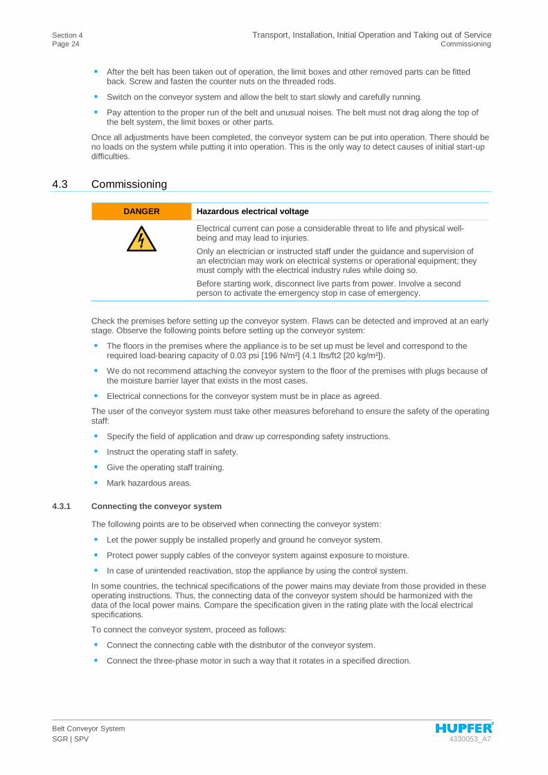
4.3 Commissioning
DANGER Hazardous electrical voltage
Electrical current can pose a considerable threat to life and physical well-being and may lead to injuries. Only an electrician or instructed staff under the guidance and supervision of an electrician may work on electrical systems or operational equipment; they must comply with the electrical industry rules while doing so. Before starting work, disconnect live parts from power. Involve a second person to activate the emergency stop in case of emergency.
Check the premises before setting up the conveyor system. Flaws can be detected and improved at an early stage. Observe the following points before setting up the conveyor system:
§ The floors in the premises where the appliance is to be set up must be level and correspond to the required load-bearing capacity of 0.03 psi [196 N/m²] (4.1 lbs/ft2 [20 kg/m²]).
§ We do not recommend attaching the conveyor system to the floor of the premises with plugs because of the moisture barrier layer that exists in the most cases.
§ Electrical connections for the conveyor system must be in place as agreed.
The user of the conveyor system must take other measures beforehand to ensure the safety of the operating staff:
§ Specify the field of application and draw up corresponding safety instructions.
§ Instruct the operating staff in safety.
§ Give the operating staff training.
§ Mark hazardous areas.
4.3.1 Connecting the conveyor system
The following points are to be observed when connecting the conveyor system:
§ Let the power supply be installed properly and ground he conveyor system.
§ Protect power supply cables of the conveyor system against exposure to moisture.
§ In case of unintended reactivation, stop the appliance by using the control system.
In some countries, the technical specifications of the power mains may deviate from those provided in these operating instructions. Thus, the connecting data of the conveyor system should be harmonized with the data of the local power mains. Compare the specification given in the rating plate with the local electrical specifications.
To connect the conveyor system, proceed as follows:
§ Connect the connecting cable with the distributor of the conveyor system.
§ Connect the three-phase motor in such a way that it rotates in a specified direction.

Transport, Installation, Initial Operation and Taking out of Service Section 4 Decommissioning, Storage and Recycling Page 25
Belt Conveyor System 4330053_A7 SGR | SPV
Electrical connections SPV/SGR
Control system and power distribution
SGR SPV cold SPV-I SPV-II SPV-III
Number of 230 V sockets
- 0 8 12 18
Electrical supply 230V~, N/PE 230V~, N/PE 400V 3~, N/PE 400V 3~, N/PE 400V 3~, N/PE
Cable cross section Q
3x2.5 mm² 3x2.5 mm² 5x6.0 mm² 5x10.0 mm² 5x16.0 mm²
The cable cross sections given above are a recommendation of HUPFER®. Dimensions of cross sections depending on the length and consumption can vary considerably.
4.3.2 Measures for Putting the Appliance into Operation
There should be no loads on the system while putting it into operation.
Check the following while putting the conveyor system into operation to ensure the safety:
§ Pay attention to unusual noises.
§ Check whether the belt runs properly (readjust the belt, if necessary).
§ Conveyor system, light barrier and limit switch must be free of foreign objects.
§ Unlock the Emergency stop button.
§ Set the potentiometer.
The conveyor system may be put into operation once its correct functioning has been ensured.
4.4 Decommissioning, Storage and Recycling
Proceed as follows to take the conveyor system out of operation:
§ Take the conveyor system out of operation and secure it against unauthorised reactivation.
§ Switch off the conveyor system and the motor at the mains.
The conveyor system must be kept in a dry, frost-free environment when placed in temporary storage. The conveyor system must be kept covered with a suitable covering material to be protected against dust ingress.
The appliance kept in the storage location must be checked for damage and corrosion every 6 months.
NOTE Condensation Ensure that there is sufficient ventilation and no major variations in
temperature in the storage location to prevent condensation from forming.
Before the appliance is taken back into operation, it must be clean and dry.
To dismantle the conveyor system, proceed as follows:
§ Remove the belt.
§ Dismantle the control and operating controls.
§ Dismantle the conveyor system starting with the first segment at the beginning of the belt system.
§ Dismantle all segments up to the end of the belt system.
§ Clean the machine parts to remove used lubricants.
§ Remove all seals from the bearings.
§ Separate all the plastic, electronics and metal parts from each other.

Section 4 Transport, Installation, Initial Operation and Taking out of Service Page 26 Decommissioning, Storage and Recycling
Belt Conveyor System SGR | SPV 4330053_A7
If the conveyor system needs to be recycled, all the operating and auxiliary materials must be disposed in an environmentally compatible manner. Recyclable materials must be properly separated and disposed of in an environmentally compatible manner in accordance with local Waste Disposal Regulations. The local agencies responsible for disposal must be contacted regarding removal. Separate the reusable materials of the appliance (casters and plastic parts) before disposing of or send the appliance to a recycling centre. Dispose of the electronics at corresponding collection centres.
We offer our customers to dispose of their waste appliances. Please contact us or one of our distribution partners.
Packaging and packing material can be sent to the recycling centre by indicating the waste disposal contract number. If you do not have the valid waste disposal contract number, you can request it from HUPFER® -Service.
NOTE Disposal of electrical equipment Electrical equipment is not a part of household refuse.
Please return the machine to the manufacturer for disposal purposes: HUPFER® Metallwerke GmbH & Co. KG Dieselstrasse 20 48653 Coesfeld ℡ +49 2541 805-0 6 +49 2541 805-111 www.hupfer.de [email protected]

Operation Section 5 Arrangement and Function of the Controls Page 27
Belt Conveyor System 4330053_A7 SGR | SPV
5 Operation
DANGER Defective emergency stop
In case of fault, e.g. from defective fuses, the drives may continue to run even after the emergency stop has been pressed.
CAUTION Rotating machine parts
Avoid any direct contact with the running conveyor belt and the outlet, feeding and deflection points during operation or when performing any other work. There is an indirect risk of injuries of the fingers caused by being pulled into the appliance and crushing. Never reach into the hazardous area of the conveyor system during operation. Before switching on the conveyor system, make sure there is no risk of reactivation of the belt.
5.1 Arrangement and Function of the Controls
Figure 6 Controls
1 Main switch (SGR only) 4 Stop button 2 Emergency Stop button 5 Start button 3 Potentiometer
Position number
Control Function
1 Main switch (SGR only) Switches the conveyor system on.
2 Emergency Stop button Is used to switch off the appliance quickly in case of emergency. If you have pressed the Emergency Stop button, the power supply of the drives of the whole conveyor system will be interrupted.
3 Potentiometer Controls the speed of the belt: V min. = 13 ft/min. (4 m/min.) V max. = 66 ft/min. (20 m/min.)
4 Stop button Stops the conveyor system if needed.
5 Start button Starts the conveyor system.
Section 5 Operation Page 28 Operation
Belt Conveyor System SGR | SPV 4330053_A7
5.2 Operation
CAUTION Rotating machine parts
Avoid any direct contact with the running conveyor belt and the outlet, feeding and deflection points during operation or when performing any other work. There is an indirect risk of injuries of the fingers caused by being pulled into the appliance and crushing. Never reach into the hazardous area of the conveyor system during operation. Before switching on the conveyor system, make sure there is no risk of reactivation of the belt. Ensure that your fingers do not get caught under the belt when performing work at the conveyor system. Do not wear any loose-fitting clothing, such as scarves or ties, during operations.
Place the trays on the belt uniformly to ensure a smooth transport.
The conveyor system keeps on running automatically. If necessary, you can manually intervene in the conveying process via the operating console.
Switching on:
§ Set the main switch (1) on the SGR from the switch position 0 to the switch position 1. The system is switched on and ready for operation.
§ Set the belt speed on the potentiometer (4) to the value 1-2.
§ Press the green start button (3) or the foot switch (option) to start the conveyor system.
Switching off / stop:
§ The belt of the conveyor system will automatically stop moving if the light barrier has been interrupted.
§ Press the red stop button (2) or the foot switch (option) to stop the conveyor system, if required.
§ Set the main switch (1) on the SGR from the switch position 1 to the switch position 0. As a result, the conveyor system will switch off.
5.3 Measures at the End of Use
CAUTION Rotating machine parts
Avoid any direct contact with the running conveyor belt and the outlet, feeding and deflection points during operation or when performing any other work. There is an indirect risk of injuries of the fingers caused by being pulled into the appliance and crushing. Never reach into the hazardous area of the conveyor system during operation. Wait until the belt comes to a standstill.
To take the conveying device out of operation, proceed as follows:
§ Make sure that no more trays are placed onto the conveying device and that the conveyor belt is cleared up.
§ Switch off the conveyor system on the control panel.
§ Disconnect the conveyor system from the mains with the main switch.

Troubleshooting and Repair Section 6 Safety Measures Page 29
Belt Conveyor System 4330053_A7 SGR | SPV
6 Troubleshooting and Repair
6.1 Safety Measures
DANGER Hazardous electrical voltage
Electrical current can pose a considerable threat to life and physical well-being and may lead to injuries. Before performing troubleshooting, take the conveyor system out of operation and secure it against unauthorised reactivation.
CAUTION Rotating machine parts
There is an indirect risk of injuries of the fingers caused by being pulled into the appliance and crushing. Never reach into the hazardous area of the conveyor system while examining the system for faults and performing troubleshooting. Ensure that your fingers do not get caught under the belt when performing work at the conveyor system.
6.2 Instructions regarding Fault Repair
Servicing may be carried out by authorised specialists only.
Defective components may only be replaced with HUPFER® original parts. The modular design simplifies the replacement of individual components.
In the event of after-sales service and when ordering spare parts specify always the data given in the rating plate.
Regular inspections and maintenance of the appliance prevent disruptions to operation and ensure safety.
6.3 Fault and Action Table
Only a specialist staff authorised by HUPFER® may perform troubleshooting work.
Fault Cause Measures
The conveyor system does not run Defective on site fuses Fuses to be checked and replaced by a qualified electrician, if required
Defective mains connecting cable or mains plug
Have the disruption checked and repaired by a qualified electrician.
Defective switch device Have the disruption checked and repaired by a qualified electrician.
Emergency Stop button has been pressed (the green ring cannot be seen)
Unlock the Emergency Stop button (the green ring is visible)
Main switch is not turned on Turn on the main switch
Defective fine fuses Fault to be checked and repaired by a qualified electrician
Energy optimisation device switches on
Fault to be checked and repaired by a qualified electrician
Foot switch is not activated Press the foot switch
The speed cannot be adjusted Defective potentiometer or control unit
Fault to be checked and repaired by a qualified electrician

Section 6 Troubleshooting and Repair Page 30 Fault and Action Table
Belt Conveyor System SGR | SPV 4330053_A7
Fault Cause Measures
Motor does not run Fuse is blown Fuses to be checked and replaced by a qualified electrician, if required
Overload protection has been triggered
Switch on the overload protection and if needed let the fault be checked and repaired by a qualified electrician
Defective motor control unit (frequency converter)
The control unit may not to be checked and replaced by a qualified electrician.
Defective motor The motor may need to be checked and replaced by a qualified electrician.
The conveyor system does not convey
The conveyor belt is overloaded, the drive spins around
Take some loads off the conveyor belt and check and restretch the belt, if necessary
The conveyor system conveys too quickly
Frequency converter setting is too high
Change potentiometer settings
The conveyor systems does not switch off
Defective relay Fault to be checked and repaired by a qualified electrician
Defective light barrier Fault to be checked and repaired by a qualified electrician
Defective button Fault to be checked and repaired by a qualified electrician
Defective control system Fault to be checked and repaired by a qualified electrician
Running noises There is either too much free space for the belt or the belt is stretched too much
Check and if needed adjust the tension
Defective bearings in the casters Fault to be checked and repaired by a qualified electrician
Dirty surface clean
Conveyor belt run, one-sided The belt is stretched on one side Check and adjust the tension
Impurities between the belt and driving roller and/or deflection pulley
Clean and readjust the driving roller and/or deflection pulley
The belt runs obliquely The tension is too low Check and adjust the tension
Care and Maintenance Section 7 Safety Measures Page 31
Belt Conveyor System 4330053_A7 SGR | SPV
7 Care and Maintenance
7.1 Safety Measures
DANGER Hazardous electrical voltage
Electrical current can pose a considerable threat to life and physical well-being and may lead to injuries. Before performing cleaning and maintenance work, take the conveyor system out of operation and secure it against unauthorised reactivation.
CAUTION Rotating machine parts
There is a risk of injury caused by being pulled into the appliance and crushing. Before performing cleaning and maintenance work, take the conveyor system out of operation and secure it against unauthorised reactivation. Avoid direct contact with the running belt and the outlet, feeding and deflection points. Never reach into the hazardous area of the conveyor system.
CAUTION Risk of damages to property
Due to defective maintenance there is a risk of injury and equipment damage. Meet the maintenance intervals and the specified deadlines for regular checks and inspections.
7.2 Hygiene Measures
It is essential for operating staff to act in the correct manner to ensure optimal hygiene.
Everyone must be informed about local applicable hygiene regulations, observe them and comply with them.
Use a waterproof plaster to cover wounds on hands and arms.
Never sneeze or cough on clean trays or crockery items.
7.3 Notes on Care and Maintenance Measures
CAUTION Appliance damage
Never use chloride-containing cleaning agents, abrasive cleaning powder or steel wool to clean the controls. Aggressive cleaning agents can destroy plastics and scratch the display. Use lukewarm water and a soft cloth to clean the control panel.
Never clean the running conveyor system. Do not clean the conveyor system with steam-jet or high-pressure cleaners. Take the conveyor system out of operation and switch it off at the mains in any area where steam-jet or high-pressure cleaners are to be used.
Dry well the conveyor system after the wet and moist cleaning to avoid the development of mould and growth of germs and bacteria. Let the belt dry well after cleaning.
The use of degreasing, chlorine-free agents (e.g. soapy water used normally in kitchens) and cleaning cloth is sufficient for cleaning. PVC surfaces are never to be cleaned with solvents and aggressive substances.

Section 7 Care and Maintenance Page 32 Notes on Care and Maintenance Measures
Belt Conveyor System SGR | SPV 4330053_A7
7.3.1 Table of care measures
Care and inspection measures
Action
dai
ly
wee
kly
mon
thly
Int
erva
l
Top and bottom of the belt clean x
Surface of the conveyor system clean x
Cleaning drawer and scraper clean x
Impurities between casters and the belt remove x
7.3.2 Maintenance table
To ensure a long-lasting lifetime of the conveyor system, the regular maintenance is required. Appeared faults or damages should be eliminated immediately.
Maintenance measures
Action
dai
ly
wee
kly
mon
thly
Int
erva
l
Visual inspection of the conveyor system for mechanical damages
carry out x
Belt between the casters and the belt for impurities check x
Visual inspection of the electrical installation carry out x1
Connecting cable and mains plug for mechanical damages check x1
Protective earth conductor check x1
Function of the main switch check x
Function of the Emergency Stop button check x
Engine box and deflection box clean x
Function of the mechanical parts check x
Belt for damages and wear check x
Belt tension check x
Bearing of the drive and deflection side check x
Function of the limit switch check x
Function of the conveyor rollers check x
Chain tension check x
Chain Lubricate x x1 = every 6 months

Care and Maintenance Section 7 Special Care Instructions Page 33
Belt Conveyor System 4330053_A7 SGR | SPV
7.4 Special Care Instructions
Resistance to corrosion in stainless steel is provided by a passive layer which is formed on the surface when oxygen is absorbed. The oxygen in the air is sufficient for the formation of the passive layer inasmuch as faults or damage to the passive layer can be remedied again automatically by mechanical action.
The passive layer develops or is renewed more quickly when the steel comes into contact with water containing oxygen. The passive layer can be chemically damaged or breached by agents which have a reducing (oxygen-consuming) effect when they come into contact with steel at concentrated levels or at high temperatures.
Such aggressive substances include:
§ Substances containing salt and sulphur
§ Chlorides (salts)
§ Seasoning concentrates (e.g. mustard, vinegar essence, seasoning cubes, saline solutions)
Further damages can occur due to:
§ Extraneous rust (e.g. from other components, tools or rust film)
§ Iron particles (e.g. grinding dust)
§ Contact with non-ferrous metals (element formation)
§ Lack of oxygen (e.g. no admission of air, low-oxygen water).
General working principles for handling appliances made of "refined stainless steel":
§ Always keep the surface of appliances made from stainless steel clean and open to air.
§ Use cleaning agents suitable for stainless steel. Never use bleaching cleaning agents or any containing chlorides.
§ Remove layers of lime scale, grease, starch and egg-white by cleaning daily. Corrosion may occur underneath these layers due to lack of air absorption.
§ Once the appliance has been cleaned, remove all cleaning agent residues by wiping thoroughly with plenty of water. The surface should be thoroughly dried after wiping.
§ Do not bring items made of stainless steel into contact with substances such as concentrated acids, seasonings and salts for longer than is absolutely necessary. Acid fumes emitted when tiles are cleaned also cause corrosion in "refined stainless steel".
§ Avoid damaging the surface of the stainless steel, especially by bringing into contact with metals other than stainless steel.
§ Residues from other metals produce extremely small amounts of chemical elements which can cause corrosion. Contact with iron and steel must be avoided at all costs, because it will cause extraneous rust. If stainless steel comes into contact with iron (steel wool, steel particles from pipes, water containing iron), this can trigger corrosion. Therefore, only use refined steel wool or brushes with natural, plastics or refined steel bristles only for physical cleaning. Steel wool or brushes with unalloyed steel cause extraneous rust due to abrasion.

Section 8 Spare Parts and Accessories Page 34 Introduction
Belt Conveyor System SGR | SPV 4330053_A7
8 Spare Parts and Accessories
8.1 Introduction
Servicing should be carried out by authorised specialists only.
Defective components should only be replaced with HUPFER® original parts or identical spare parts. That is the only way to guarantee a safe operation. We would like to point out that a perfect functionality of the appliance can only be ensured if you use recommended original parts by HUPFER®. Unsuitable or partially suitable spare parts can void the warranty.
Spare parts and accessories can be ordered at HUPFER® Service (Tel. +49 2541 805-0). When ordering spare parts or after-sales services, always specify the order number and specifications on the rating plate. Please specify the required belt length when ordering spare parts.
8.2 Spare Parts and Accessories List
Drawing number Item designation Type
21.89 (0191093370) Button Emergency stop 1S 1Ö complete
0116300656 Button "Start" 51/41/30 grey Polymer
21.89 (0116300657) Button "Stop" 51/41/30 grey Polymer
21.89 (0191028022) Potentiometer 77/41/30 complete
21.89 (015220511) Frequency converter
240V 0.25kW
0191163394 Sensor Reed magnetic 1Ö
21.89 (0191008557) Light barrier E3S-AR 31
0116300658 foot switch PA66 72/97/28 12 - 230V black
21.89 (0191100340) Floor fastening Stainless steel 105/75/52 cpl Stainless steel
0191128732 Holder 38/18/10 black Polymer
21.89 (0191042205) Magnet Ø15/5 adhesive force 90N
21.89 (0191086628) Drive drum Ø76/320/440/Ø20 Stainless steel
0191086625 Deflection drum Ø76/320/440 Stainless steel
014002525 Threaded leg PA Ø70/170 40x40 black set (Package contents: 2 piece)
21.89 (0191029491) Gear motor 230/400V 50Hz 0.25KW
21.89 (0116301163) Shaft Ø18/150 Stainless steel
0191030248 Sprocket wheel C45 3/8" x 7/32" Z 19
21.89 (0191075894) Drive chain Belt 505 mm long, complete
21.89 (015223024) Double link cropped 3/8" C-06B-1 (Package contents: 1 unit 5223024)
21.89 (015223023) Connecting link 3/8" x 7/32" (Package contents: 1 unit 5223023)
21.89 (0116300554) Lower belt roller 431/50/28
0116301248 Belt Variable length
Annex Section 9 Monthly Maintenance Checklist Page 35
Belt Conveyor System 4330053_A7 SGR | SPV
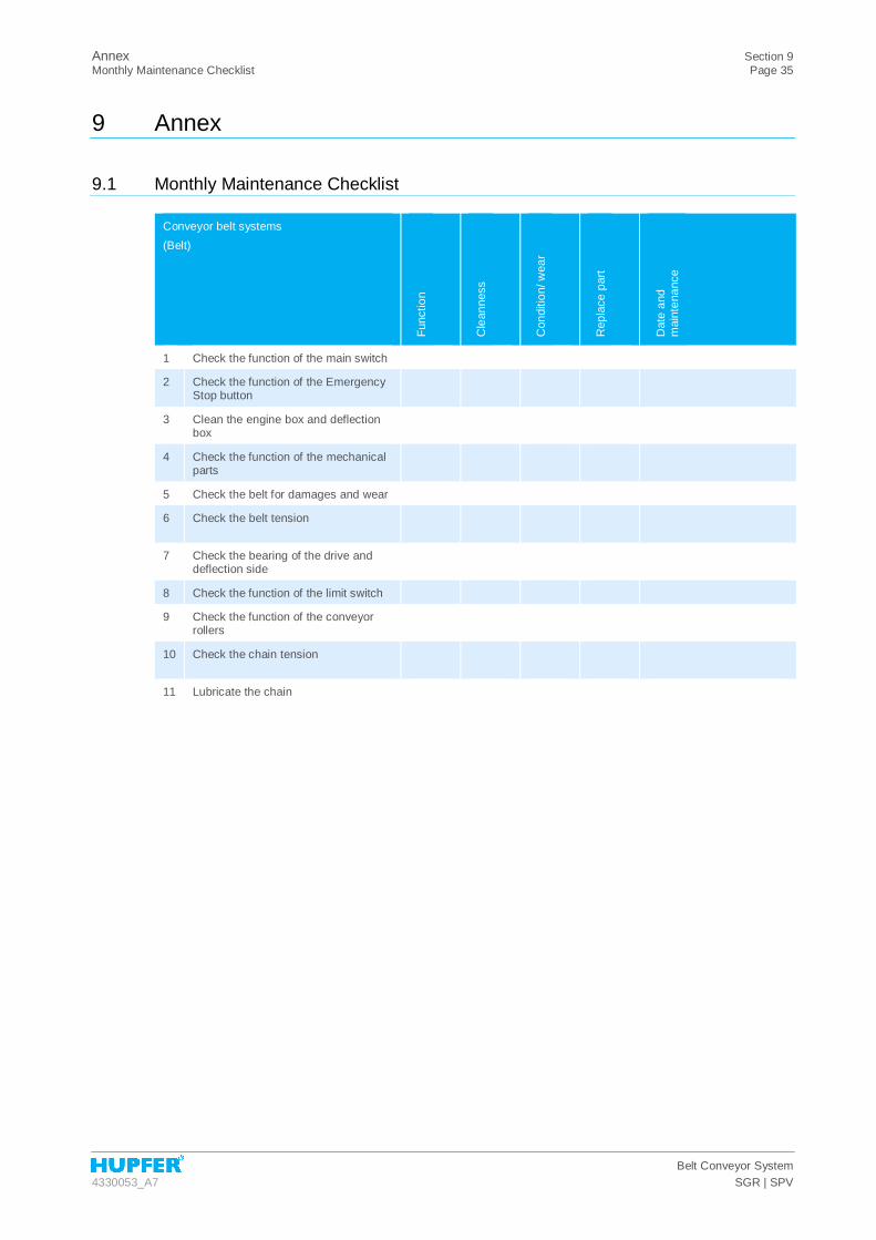
9 Annex
9.1 Monthly Maintenance Checklist
Conveyor belt systems (Belt)
Func
tion
Cle
anne
ss
Con
ditio
n/ w
ear
Rep
lace
par
t
Dat
e an
d m
aint
enan
ce
1 Check the function of the main switch
2 Check the function of the Emergency Stop button
3 Clean the engine box and deflection box
4 Check the function of the mechanical parts
5 Check the belt for damages and wear
6 Check the belt tension
7 Check the bearing of the drive and deflection side
8 Check the function of the limit switch
9 Check the function of the conveyor rollers
10 Check the chain tension
11 Lubricate the chain

Section 9 Annex Page 36 Safety Instruction Protocol
Belt Conveyor System SGR | SPV 4330053_A7
9.2 Safety Instruction Protocol
The following staff members have received instruction on safety procedures. They have read and understood the operating instructions.
Name Signature / date

Annex Section 9 EC Declaration of Conformity Page 37
Belt Conveyor System 4330053_A7 SGR | SPV
9.3 EC Declaration of Conformity

Section 9 Annex Page 38 EC Declaration of Conformity
Belt Conveyor System SGR | SPV 4330053_A7


![SERVANT - sgr-store.com1].pdf · 2019 SGR SERVANT LEADERSHIP CONFERENCE. TABLE OF . CONTENTS. 2019 SGR SERVANT LEADERSHIP CONFERENCE PACIFIC NORTHWEST. 2019_SGR_Conference_PNW_Guide.](https://static.fdocuments.us/doc/165x107/5f5a796013ea3c79ea64a464/servant-sgr-storecom-1pdf-2019-sgr-servant-leadership-conference-table-of.jpg)