
Bell Housings & Gaskets -...
49
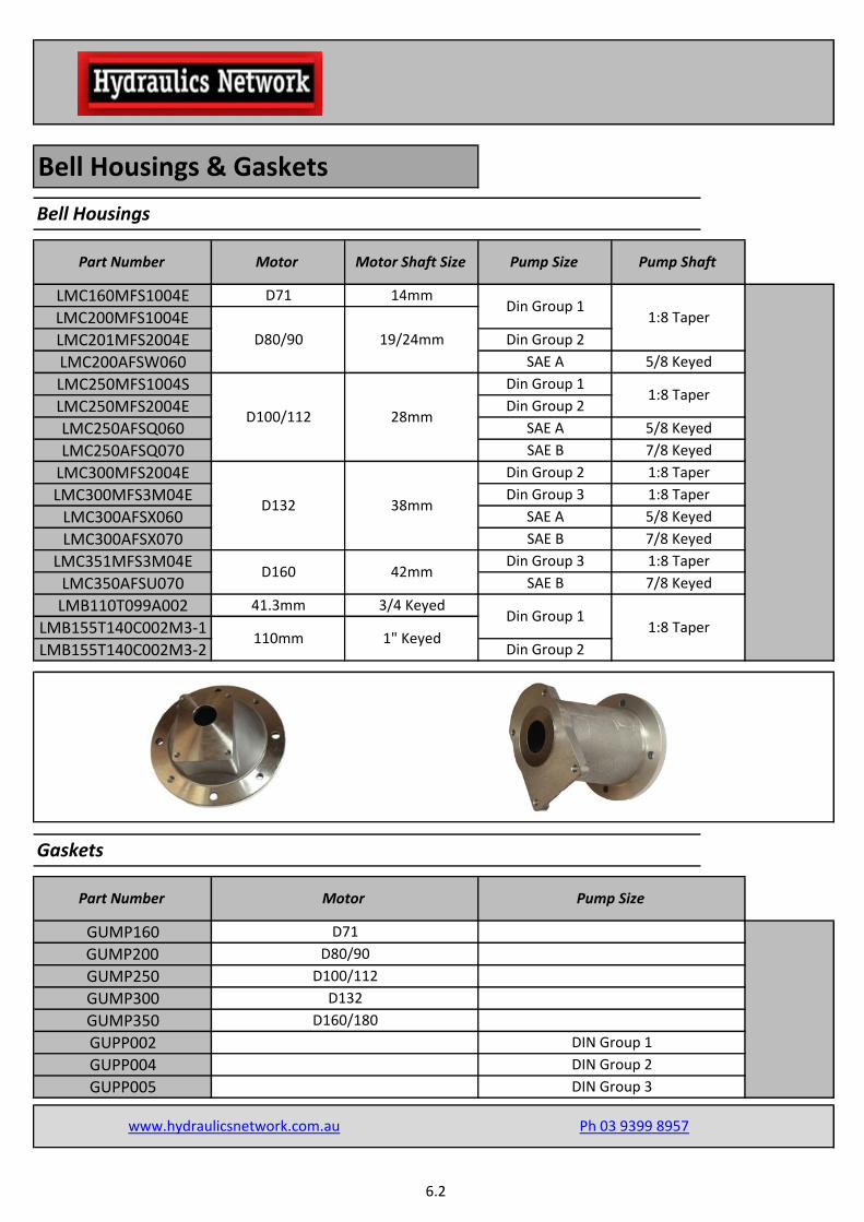
LMC160MFS1004E D71 14mm Din Group 1 1:8 Taper LMC200MFS1004E Bell Housings & Gaskets Bell Housings Part Number Motor Motor Shaft Size Pump Size Pump Shaft 5/8 Keyed LMC250MFS1004S Din Group 1 1:8 Taper LMC250MFS2004E Din Group 2 LMC201MFS2004E Din Group 2 LMC200AFSW060 SAE A 5/8 Keyed LMC250AFSQ060 SAE A 5/8 Keyed LMC300MFS2004E D132 38mm Din Group 2 1:8 Taper 3/4 Keyed Din Group 1 1:8 Taper LMC350AFSU070 SAE B 7/8 Keyed LMC300AFSX070 SAE B 7/8 Keyed LMC351MFS3M04E D160 42mm Din Group 3 1:8 Taper LMC300MFS3M04E Din Group 3 1:8 Taper LMC300AFSX060 SAE A Gaskets Part Number Motor Pump Size www.hydraulicsnetwork.com.au Ph 03 9399 8957 D80/90 LMC250AFSQ070 D100/112 28mm SAE B 7/8 Keyed 19/24mm LMB155T140C002M3-1 110mm 1" Keyed LMB155T140C002M3-2 Din Group 2 LMB110T099A002 41.3mm GUMP160 GUMP200 D71 D80/90 D160/180 DIN Group 2 DIN Group 3 D100/112 D132 GUPP005 GUMP350 GUPP002 GUPP004 GUMP250 GUMP300 DIN Group 1 6.2
-
Upload
vuongthien -
Category
Documents
-
view
247 -
download
1
Transcript of Bell Housings & Gaskets -...
LMC160MFS1004E D71 14mmDin Group 1
1:8 TaperLMC200MFS1004E
Bell Housings & Gaskets
Bell Housings
Part Number Motor Motor Shaft Size Pump Size Pump Shaft
5/8 Keyed
LMC250MFS1004S Din Group 11:8 Taper
LMC250MFS2004E Din Group 2
LMC201MFS2004E Din Group 2
LMC200AFSW060 SAE A
5/8 Keyed
LMC250AFSQ060 SAE A 5/8 Keyed
LMC300MFS2004E
D132 38mm
Din Group 2 1:8 Taper
3/4 KeyedDin Group 1
1:8 Taper
LMC350AFSU070 SAE B 7/8 Keyed
LMC300AFSX070 SAE B 7/8 Keyed
LMC351MFS3M04ED160 42mm
Din Group 3 1:8 Taper
LMC300MFS3M04E Din Group 3 1:8 Taper
LMC300AFSX060 SAE A
Gaskets
Part Number Motor Pump Size
www.hydraulicsnetwork.com.au Ph 03 9399 8957
D80/90
LMC250AFSQ070
D100/112 28mm
SAE B 7/8 Keyed
19/24mm
LMB155T140C002M3-1110mm 1" Keyed
LMB155T140C002M3-2 Din Group 2
LMB110T099A002 41.3mm
GUMP160
GUMP200
D71
D80/90
D160/180
DIN Group 2
DIN Group 3
D100/112
D132
GUPP005
GUMP350
GUPP002
GUPP004
GUMP250
GUMP300
DIN Group 1
6.2

Couplings
Motor Side Couplings
Part Number Motor Shaft Size Series Material
SGES31FS300
19mm
24mm
SGEA01M02028FG D71 14mm
SGEA01M03048FG
0
13/4"
SGEA31G020502EFG SAE B
DIN Group 3 1:8 Taper 3
Pump Side Couplings
www.hydraulicsnetwork.com.au Ph 03 9399 8957
D80
D90
D100/112
Engine
D132
D160
SGEA21G040502FFG 2
SGEA31M06077FG 3
SGEA51M07109FG 5
SGEA21M04048FG 2
SGEA21M05055FG 2
0
DIN Group 2
5SGEA51G020502EFG
Part Number Pump Shaft Size Series Material
28mm
1"
38mm
42mm
Aluminium
SGEA01G01050FG Engine
Coupling Elements
7/8" Keyed 3
SGEA01FS100 DIN Group 1 1:8 Taper 0
Aluminium
1:8 Taper 2
SGEA21L00050FG SAE A 5/8" Keyed 2
SGEA21FS100 DIN Group 1 1:8 Taper 2
SGEA21FS200
SGEA31FS200 DIN Group 2 1:8 Taper 3
Oil Resistant
Rubber
Shore Hardness 87EGE3 3 85mm 380
EGE5 5 109.5mm 620
EGE0
SAE B 7/8" Keyed
SGES51FS300 DIN Group 3 1:8 Taper 5
0 43mm 20
EGE2 2 68mm
Part Number Series Diameter Max Torque Material
190
6.3
DATA REQUIRED
Electric motor power/motor size
Manufacturer and pump type
TO VERIFY:
1 - Pump and motor shaft dimensions (see page 69)
2 - Shaft and flange pump (see pump data sheet)
Example:
- Electric motor 2 kW - 4 poles - Motor size 110/112
- Atos pump code PFE31 - Shaft 1
AA gguuiiddee ttoo sseelleecctt tthhee ccoorr rr eecctt bbee ll ll --hhoouuss iinngg aanndd ddrr ii vvee ccoouupp ll iinngg ccoommppoonneennttss
8
250 4,76
60 57,5
9,5
28 19,05
Nr. 2x11
Ø 82,55
Ø 106,4
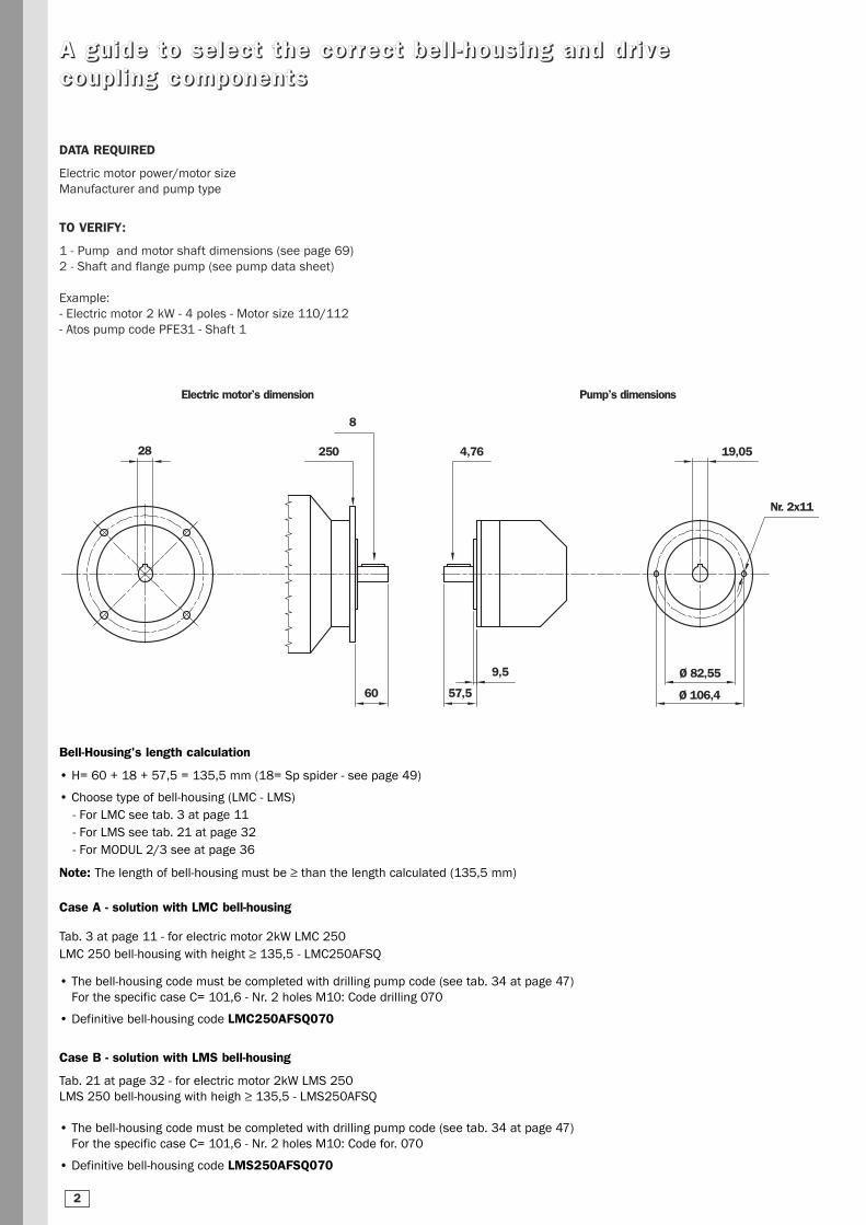
Bell-Housing's length calculation
• H= 60 + 18 + 57,5 = 135,5 mm (18= Sp spider - see page 49)
• Choose type of bell-housing (LMC - LMS)
- For LMC see tab. 3 at page 11
- For LMS see tab. 21 at page 32
- For MODUL 2/3 see at page 36
Note: The length of bell-housing must be ≥ than the length calculated (135,5 mm)
Case A - solution with LMC bell-housing
Tab. 3 at page 11 - for electric motor 2kW LMC 250
LMC 250 bell-housing with height ≥ 135,5 - LMC250AFSQ
• The bell-housing code must be completed with drilling pump code (see tab. 34 at page 47)
For the specific case C= 101,6 - Nr. 2 holes M10: Code drilling 070
• Definitive bell-housing code LMC250AFSQ070
Case B - solution with LMS bell-housing
Tab. 21 at page 32 - for electric motor 2kW LMS 250
LMS 250 bell-housing with heigh ≥ 135,5 - LMS250AFSQ
• The bell-housing code must be completed with drilling pump code (see tab. 34 at page 47)
For the specific case C= 101,6 - Nr. 2 holes M10: Code for. 070
• Definitive bell-housing code LMS250AFSQ070
Electric motor’s dimension Pump’s dimensions
2

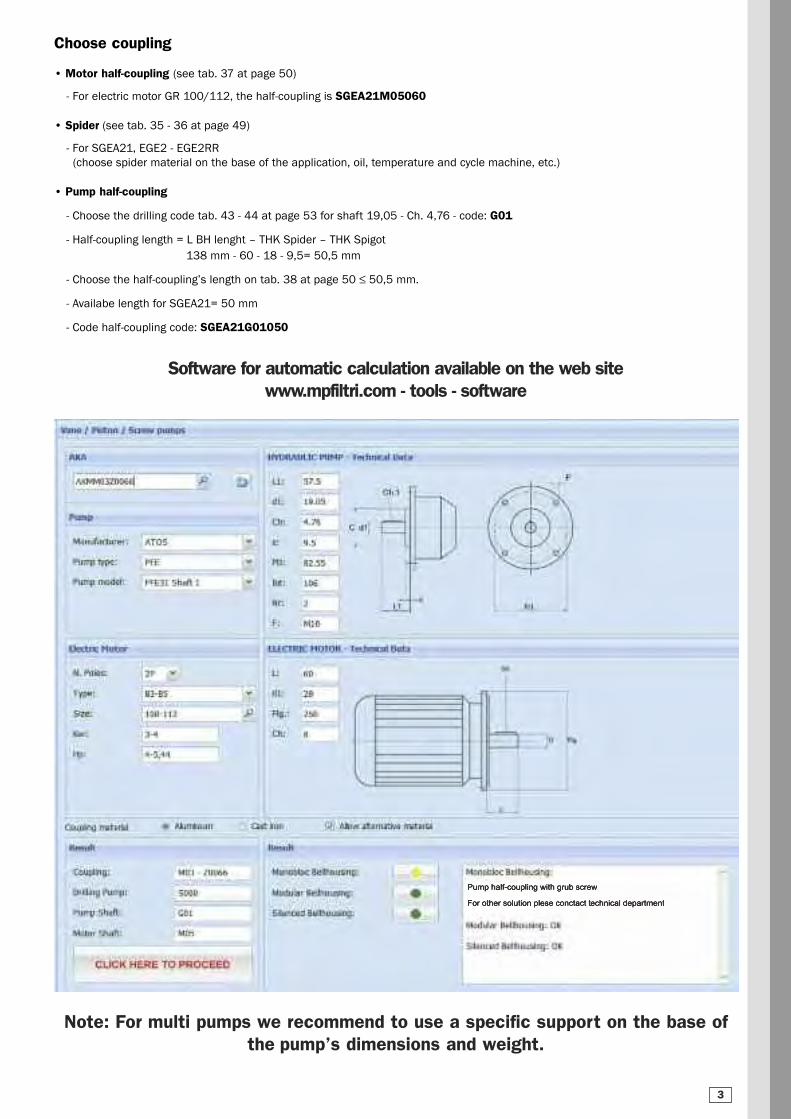
Choose coupling
• Motor half-coupling (see tab. 37 at page 50)
- For electric motor GR 100/112, the half-coupling is SGEA21M05060
• Spider (see tab. 35 - 36 at page 49)
- For SGEA21, EGE2 - EGE2RR
(choose spider material on the base of the application, oil, temperature and cycle machine, etc.)
• Pump half-coupling
- Choose the drilling code tab. 43 - 44 at page 53 for shaft 19,05 - Ch. 4,76 - code: G01
- Half-coupling length = L BH lenght – THK Spider – THK Spigot
138 mm - 60 - 18 - 9,5= 50,5 mm
- Choose the half-coupling’s length on tab. 38 at page 50 ≤ 50,5 mm.
- Availabe length for SGEA21= 50 mm
- Code half-coupling code: SGEA21G01050
Software for automatic calculation available on the web sitewww.mpfiltri.com - tools - software
Note: For multi pumps we recommend to use a specific support on the base of the pump’s dimensions and weight.
3
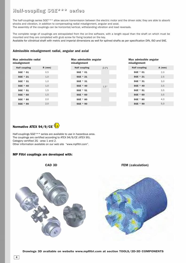
HHaall ff --ccoouuppll ii nngg SSGGEE****** sseerr iieess
The half-couplings series SGE*** allow secure transmission between the electric motor and the driven side; they are able to absorb
shocks and vibration, in addition to compensating radial misalignment, angular and axial.
The assembly of the couplings can be horizontal/vertical, withstanding vibration and load reversals.
The complete range of couplings are extrapolated from the on-line software, with a length equal than the shaft on which must be
mounted and they are completed with grub screw for fixing located on the key.
Available for cilindrical shaft with metric and imperial dimensions as well for splined shafts as per specification DIN, ISO and SAE.
Admissible misalignment radial, angular and axial
Half coupling
SGE * 01
SGE * 21
SGE * 31
SGE * 40
SGE * 51
SGE * 60
SGE * 80
SGE * 90
R (mm)
0,5
1,0
1,0
1,0
1,5
1,5
2,0
2,0
Max admissible radialmisalignment
Half coupling
SGE * 01
SGE * 21
SGE * 31
SGE * 40
SGE * 51
SGE * 60
SGE * 80
SGE * 90
b (°)
1,5°
Half coupling
SGE * 01
SGE * 21
SGE * 31
SGE * 40
SGE * 51
SGE * 60
SGE * 80
SGE * 90
A (mm)
2,0
2,5
3,0
3,5
3,5
3,5
4,0
5,0
Max admissible angularmisalignment
Max admissible angular misalignment
CAD 3D FEM (calculation)
Drawings 3D available on website www.mpfiltri.com at section TOOLS/2D-3D COMPONENTS
4
Normative ATEX 94/9/CE
Half-couplings SGE*** series are available to use in hazardous area.
The couplings are certified according to ATEX 94/9/CE (ATEX 95).
Category certified 2G - area 1 and 2.
Other information available on our web site “www.mpfiltri.com”.
MP Filtri couplings are developed with:

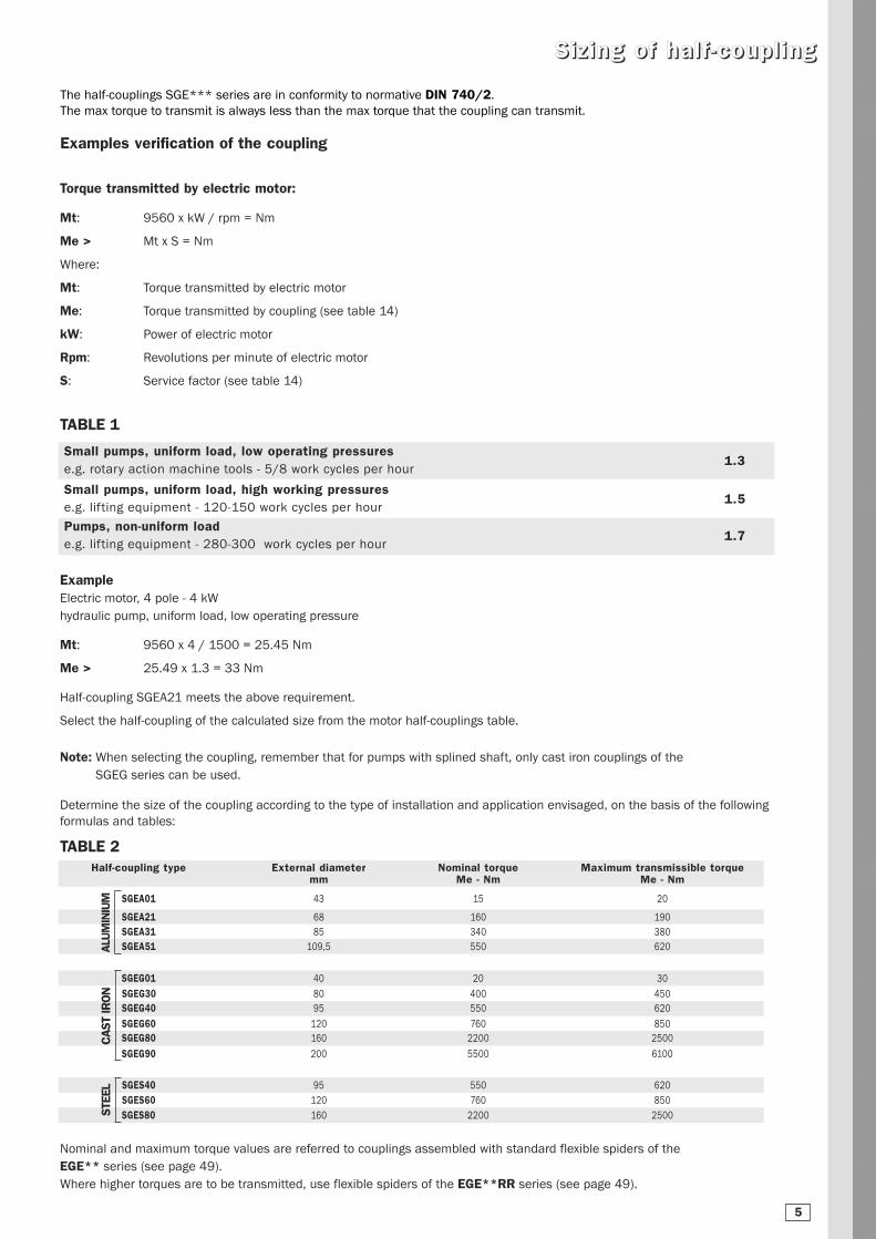
The half-couplings SGE*** series are in conformity to normative DIN 740/2.
The max torque to transmit is always less than the max torque that the coupling can transmit.
Examples verification of the coupling
SSiizz iinngg ooff hhaall ff --ccoouuppll ii nngg
Determine the size of the coupling according to the type of installation and application envisaged, on the basis of the following
formulas and tables:
Nominal and maximum torque values are referred to couplings assembled with standard flexible spiders of the
EGE** series (see page 49).
Where higher torques are to be transmitted, use flexible spiders of the EGE**RR series (see page 49).
Torque transmitted by electric motor:
Mt: 9560 x kW / rpm = Nm
Me > Mt x S = Nm
Where:
Mt: Torque transmitted by electric motor
Me: Torque transmitted by coupling (see table 14)
kW: Power of electric motor
Rpm: Revolutions per minute of electric motor
S: Service factor (see table 14)
Example Electric motor, 4 pole - 4 kW
hydraulic pump, uniform load, low operating pressure
Mt: 9560 x 4 / 1500 = 25.45 Nm
Me > 25.49 x 1.3 = 33 Nm
Half-coupling SGEA21 meets the above requirement.
Select the half-coupling of the calculated size from the motor half-couplings table.
Small pumps, uniform load, low operating pressurese.g. rotary action machine tools - 5/8 work cycles per hour
1.3
Small pumps, uniform load, high working pressurese.g. lifting equipment - 120-150 work cycles per hour
1.5
Pumps, non-uniform loade.g. lifting equipment - 280-300 work cycles per hour
1.7
Half-coupling type External diameter Nominal torque Maximum transmissible torquemm Me - Nm Me - Nm
SGEA01 43 15 20
SGEA21 68 160 190
SGEA31 85 340 380
SGEA51 109,5 550 620
Note: When selecting the coupling, remember that for pumps with splined shaft, only cast iron couplings of the
SGEG series can be used.
TABLE 2
TABLE 1
SGEG01 40 20 30
SGEG30 80 400 450
SGEG40 95 550 620
SGEG60 120 760 850
SGEG80 160 2200 2500
SGEG90 200 5500 6100
ALU
MIN
IUM
CAST
IRO
N
SGES40 95 550 620
SGES60 120 760 850
SGES80 160 2200 2500STEE
L
5

Noise is a particularly pervasive problem so much so that there have been statutory regulations in place now for some years, designed to limit harmful occupational exposure.Many of the machines used in industry today are equipped with oil-hydraulic systems, which happen to be a major source of noise.
1. Theory and definition of noise
From a health and hygiene standpoint, noise can be defined as an unpleasant and undesirable sound, or an unpleasant and
annoying or intolerable auditory sensation (noise being any sound phenomena that may be accompanied by sensations of
disturbance and pain). By definition, acoustic phenomena are oscillatory in character, propagated in a flexible medium
and causing pressure variations at the points, and the areas adjacent to those points, through which they pass.
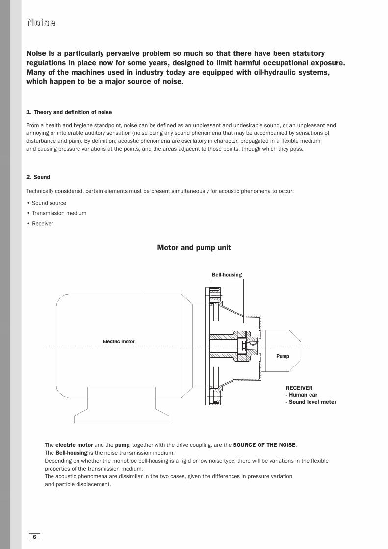
2. Sound
Technically considered, certain elements must be present simultaneously for acoustic phenomena to occur:
• Sound source
• Transmission medium
• Receiver
NNooiissee
The electric motor and the pump, together with the drive coupling, are the SOURCE OF THE NOISE.
The Bell-housing is the noise transmission medium.
Depending on whether the monobloc bell-housing is a rigid or low noise type, there will be variations in the flexible
properties of the transmission medium.
The acoustic phenomena are dissimilar in the two cases, given the differences in pressure variation
and particle displacement.
RECEIVER- Human ear- Sound level meter
Motor and pump unit
Electric motor
Pump
Bell-housing
6

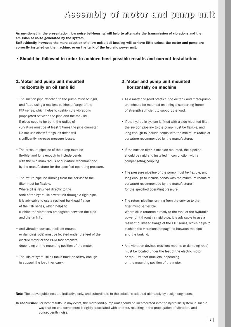
AAsssseemmbbll yy ooff mmoottoorr aanndd ppuummpp uunnii tt
As mentioned in the presentation, low noise bell-housing will help to attenuate the transmission of vibrations and the emission of noise generated by the system.Self-evidently, however, the mere adoption of a low noise bell-housing will achieve little unless the motor and pump are correctly installed on the machine, or on the tank of the hydralic power unit.
• Should be followed in order to achieve best possible results and correct installation:
1.Motor and pump unit mounted horizontally on oil tank lid
• The suction pipe attached to the pump must be rigid,
and fitted using a resilient bulkhead flange of the
FTA series, which helps to cushion the vibrations
propagated between the pipe and the tank lid.
If pipes need to be bent, the radius of
curvature must be at least 3 times the pipe diameter.
Do not use elbow fittings, as these will
significantly increase pressure losses.
• The pressure pipeline of the pump must be
flexible, and long enough to include bends
with the minimum radius of curvature recommended
by the manufacturer for the specified operating pressure.
• The return pipeline running from the service to the
filter must be flexible.
Where oil is returned directly to the
tank of the hydraulic power unit through a rigid pipe,
it is advisable to use a resilient bulkhead flange
of the FTR series, which helps to
cushion the vibrations propagated between the pipe
and the tank lid.
• Anti-vibration devices (resilient mounts
or damping rods) must be located under the feet of the
electric motor or the PDM foot brackets,
depending on the mounting position of the motor.
• The lids of hydraulic oil tanks must be sturdy enough
to support the load they carry.
2.Motor and pump unit mounted horizontally on machine
• As a matter of good practice, the oil tank and motor-pump
unit should be mounted on a single supporting frame
of strength sufficient to support the load.
• If the hydraulic system is fitted with a side-mounted filter,
the suction pipeline to the pump must be flexible, and
long enough to include bends with the minimum radius of
curvature recommended by the manufacturer.
• If the suction filter is not side mounted, the pipeline
should be rigid and installed in conjunction with a
compensating coupling.
• The pressure pipeline of the pump must be flexible, and
long enough to include bends with the minimum radius of
curvature recommended by the manufacturer
for the specified operating pressure.
• The return pipeline running from the service to the
filter must be flexible.
Where oil is returned directly to the tank of the hydraulic
power unit through a rigid pipe, it is advisable to use a
resilient bulkhead flange of the FTR series, which helps to
cushion the vibrations propagated between the pipe
and the tank lid.
• Anti-vibration devices (resilient mounts or damping rods)
must be located under the feet of the electric motor
or the PDM foot brackets, depending
on the mounting position of the motor.
Note: The above guidelines are indicative only, and subordinate to the solutions adopted ultimately by design engineers.
In conclusion: For best results, in any event, the motor-and-pump unit should be incorporated into the hydraulic system in such a
way that no one component is rigidly associated with another, resulting in the propagation of vibration, and
consequently noise.
7

TTaabbllee ooff ssuummmmaarr yy MMOODDUULL 22//33
BM
T30
0B
MT3
50
Kit
of
asse
mbl
y K
VG
5 (
Q.t
y 1
) +
Kit
of as
sem
bly
KV
G1
(Q
.ty
1)
Ø 1
90
Ø 8
5
AR
*
FR1
*
MO
DU
L 2
BM
T35
0B
MT4
00
BM
T45
0
Kit
of as
sem
bly
KV
G5
/7
(Q
.ty
2)
Ø 1
90
Ø 2
88
Ø 1
40
Ø 2
88
AD
*
FP5
FP6
FP7
BM
T550
BM
T660
BM
T800
Kit
of as
sem
bly
KVG
6/7 (
Q.t
y 1)
Ø 2
88
FP6
FP7
(BA
D8
00
O
NLY
FP
7)
5.5
- 7.5
kW
7.5
- 10.2
Hp
Siz
e 225 -
D.4
50
11 -
22
15 -
30
Hp
Siz
e 160
/1
80
D.3
50
30
40
.80
Hp
Siz
e 2
00
- D
.35
0
37
- 4
5
50
.32
- 6
1.2
Hp
Siz
e 2
25
- D
.45
0
55
- 9
0
75
- 1
25
Hp
Siz
e 2
50
/2
80
D.5
50
11
0 -
20
0
15
0 -
27
2 H
p
Siz
e 3
15
- D
.66
0
25
0 -
40
0
34
0 -
54
4 H
p
Siz
e 3
55
/4
00
D.8
00
MO
DU
L 3
8
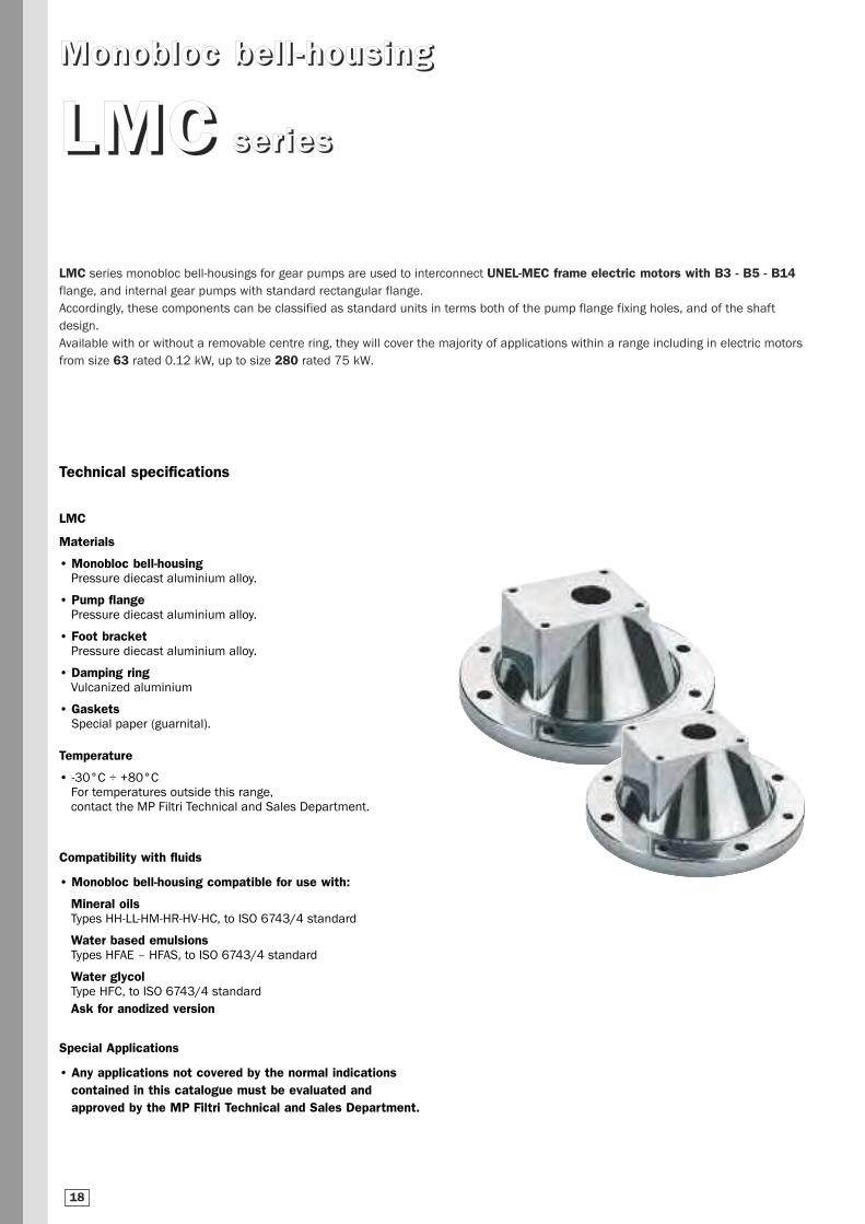
MMoonnoobblloocc bbeell ll --hhoouussiinngg
LLMMCC sseerr iieess
LMC series monobloc bell-housings for gear pumps are used to interconnect UNEL-MEC frame electric motors with B3 - B5 - B14flange, and internal gear pumps with standard rectangular flange.
Accordingly, these components can be classified as standard units in terms both of the pump flange fixing holes, and of the shaft
design.
Available with or without a removable centre ring, they will cover the majority of applications within a range including in electric motors
from size 63 rated 0.12 kW, up to size 280 rated 75 kW.
Compatibility with fluids
• Monobloc bell-housing compatible for use with:
Mineral oilsTypes HH-LL-HM-HR-HV-HC, to ISO 6743/4 standard
Water based emulsionsTypes HFAE – HFAS, to ISO 6743/4 standard
Water glycolType HFC, to ISO 6743/4 standard
Ask for anodized version
Special Applications
• Any applications not covered by the normal indications contained in this catalogue must be evaluated andapproved by the MP Filtri Technical and Sales Department.
18
Technical specifications
LMC
Materials
• Monobloc bell-housingPressure diecast aluminium alloy.
• Pump flangePressure diecast aluminium alloy.
• Foot bracketPressure diecast aluminium alloy.
• Damping ringVulcanized aluminium
• GasketsSpecial paper (guarnital).
Temperature
• -30°C ÷ +80°CFor temperatures outside this range,contact the MP Filtri Technical and Sales Department.
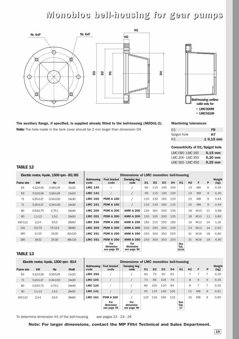
MMoonnoobblloocc bbeell ll --hhoouussiinngg ffoorr ggeeaarr ppuummppss
TABLE 12
To determine dimension H1 of the bell-housing see pages 22 - 23 - 24
The auxiliary flange, if specified, is supplied already fitted to the bell-housing (MODUL-2).
Note: The hole made in the tank cover should be 2 mm larger than dimension D4
Nr. 4xPH1
Bell-housing outlinevalid only for
• LMC300M• LMC351M
D3
D2
D1
H2Nr. 4xF
D4
Note: For larger dimensions, contact the MP Filtri Technical and Sales Department.
Dimensions of LMC monobloc bell-housing
Frame size kW Hp Shaft
63 0.12-0.18 0.16-0.24 11x23
63 0.12-0.18 0.16-0.24 11x23
71 0.25-0.37 0.34-0.50 14x30
71 0.25-0.37 0.34-0.50 14x30
80 0.53-0.75 0.75-1 19x40
90 1.1-1.5 1.5-2 24x50
100-112 2.2-4 3-5.5 28x60
132 5.5-7.5 7.5-12.5 38x80
160 11-15 15-20 42x110
180 18-22 25-30 48x110
Bell-housing Foot bracket Damping ring Weightcode code code D1 D2 D3 D4 H1 H2 F P (kg)
LMC 140 / / 95 115 140 100 13 M8 9 0,35
LMC 141 / / 95 115 140 100 13 M8 9 0,35
LMC 160 PDM A 160 / 110 130 160 110 15 M8 9 0,44
LMC 161 PDM A 160 / 110 130 160 110 15 M8 9 0,44
LMC 200 PDM A 200 ANM A 200 130 165 200 135 18 M10 11 0,68
LMC 201 PDM A 200 ANM A 200 130 165 200 135 18 M10 11 0,80
LMC 250 PDM A 250 ANM A 250 180 215 250 185 19 M12 14 1,16
LMC 300 PDM A 300 ANM A 300 230 265 300 235 23 M12 14 2,55
LMC 351 PDM A 350 ANM A 350 250 300 350 255 31 M16 18 4,90
LMC 351 PDM A 350 ANM A 350 250 300 350 255 31 M16 18 4,90
SeeTab.15-16
Electric motor, 4-pole, 1500 rpm - B3/B5
TABLE 13
Dimensions of LMC monobloc bell-housing
Frame size kW Hp Shaft
63 0.12-0.18 0.16-0.24 11x23
71 0.25-0.37 0.34-0.50 14x30
80 0.53-0.75 0.75-1 19x40
90 1.1-1.5 1.5-2 24x50
100-112 2.2-4 3-5.5 28x60
Bell-housing Foot bracket Damping ring Weightcode code code D1 D2 D3 D4 H1 H2 F P (kg)
LMC 090 / / 60 75 90 63 7 7 7 0,30
LMC 105 / / 70 85 105 74 8 6 6 0,35
LMC 120 / / 80 100 120 84 9 7 7 0,35
LMC 141 / / 95 115 140 100 13 M8 9 0,51
LMC 161 PDM A 160 / 110 130 160 110 15 M8 9 0,60
SeeTab.17
Electric motor, 4-pole, 1500 rpm - B14
Machining tolerances
D1
Spigot hole
H1
F8H7
± 0,15 mm
Concentricity of D1/Spigot hole
LMC 090 - LMC 160 0,15 mmLMC 200 - LMC 350
LMC 300 - LMC 450
0,20 mm0,25 mm
For dimension
see page 55
For dimension
see page 56
For dimension
see page 55
For dimension
see page 56
19

VVeerrss iioonnss
LMC *** 4S
LMC *** 8S
LMC *** 4E
LMC *** 8E
In order to ensure greater adaptability across a wide range of applications, LMC monobloc bell-housings for gear pumps can be supplied
in 4 different versions:
Without centre ring allowing removal of half-coupling (which as a
rule is keyed permanently to the pump shaft); motor mounting
flange drilled with 4 clearance holes + 4 threaded holes.
Used normally for vertically mounted motor and pump units
with pump submerged in the oil tank.
Without centre ring allowing removal of half-coupling (which as a
rule is keyed permanently to the pump shaft); motor mounting
flange drilled with 8 clearance holes. Used normally for vertically
mounted motor and pump units with pump submerged in the oil
tank; allows greater flexibility for directional positioning of the
hydraulic pump inside the tank, according to constructional
requirements.
With centre ring allowing removal of half-coupling (which as a
rule is keyed permanently to the pump shaft); motor mounting
flange drilled with 4 clearance holes + 4 threaded holes.
Normally used for motor and pump units mounted horizontally on
the tank lid or on the machine, for maximum ease of maintenance.
With this type of mounting, in effect, the hydraulic pump can be
removed without removing the motor.
The half-coupling mounted to the shaft passes through the
spigot hole.
With centre ring allowing removal of half-coupling (which as a
rule is keyed permanently to the pump shaft); motor mounting
flange drilled with 8 clearance holes.
Normally used for motor and pump units mounted horizontally on
the tank lid or on the machine; offers maximum ease of
maintenance, and enables directional positioning of the pump.
With this type of mounting, in effect, the hydraulic pump can be
removed without removing the motor.
The half-coupling mounted to the shaft passes through the spigot
hole.
20

05
1
2
3
3.5
Bosch
4
Spigot Pump flange Shaft Pump half-couplingPump group hole A B C Hole code type d key code
22 25.5 66 / M6 FS05M cilindrico 6 2 FS05M
22 25.5 66 / M6 FS05C cilindrico 7 2 FS05C
25.4 26.2 72 52 M6 FS100 con. 1:8 9.7 2.4 FS100
30 24.5 73 56 M6 FS1M0 cilindrico 12 3 FS1C0
30 24.5 73 56 M6 FS1M0 con. 1:8 13.9 3 FS1M0
36.5 32.5 96 71.5 M8 FS200 con. 1:8 17.2 3.2/4 FS200
50.8 43 128 98.5 M8 FS25T con. 1:8 22.2 4 FS300
50.8 42 128 98.5 M10 FS300 con. 1:8 22.2 4 FS300
50.8 43 128 98.5 M10 FS3M0 con. 1:8 22.2 4 FS300
50.8 45 137 98.5 M10 FS3T0 con. 1:8 22.2 4 FS300
60 48.5 148 127 M12 FS35M con. 1:8 25.6 4.76/5 FS350
60.3 49.5 149.5 114.3 M10 FS350 con. 1:8 25.6 4.76/5 FS350
63.5 65 196 142.8 M12 FS4M0 con. 1:8 33.3 6.35/7 FS400
63.5 64.3 188 143 M12 FS400 con. 1:8 33.3 6.35/7 FS400
32 10.3 40 40 M8 FSZBR con. 1:5 9.8 2 FSZBR
80 34.5 100 72 M8 FSZFR con. 1:5 16.9 3 FSZFR
105 48 145 102 M10 FSZGR con. 1:5 25.2 5 FSZGR
Note: For any dimensions not indicated in Table 14, see tables 15 - 16 - 17 showing motor-pump combinations.
DDeessiiggnnaatt iioonn ooff ppuummpp ff llaannggee aanndd sshhaafftt
TABLE 14
The auxiliary flange, if specified, is supplied already fitted to the bell-housing (MODUL-2).• For technical information see “DRIVE COUPLINGS”.
Spigot hole Hole
A
B
d
C
key
21

TABLE 15Components of combination
Motorsize
63
71
80
90
100112
kW
0.120.18
0.250.37
0.530.75
1.11.5
2.24
Hp
0.160.24
0.340.50
0.751
1.52
35.5
Motorshaft
11x23
14x30
19x40
24x50
28x60
Pumpcode
FS05M
FS05C
FS100
FS1C0
FS1M0
FSZBR
FS05M
FS05C
FS100
FS1C0
FS1M0
FSZBR
FS05M
FS05C
FS100
FS1C0
FS1M0
FSZBR
FS200
FSZFR
FS05M
FS05C
FS100
FS1C0
FS1M0
FSZBR
FS200
FSZFR
FS100
FS1C0
FS1M0
FSZBR
FS200
FSZFR
FS25T
FS300
FS3M0
FS3T0
Bell-housingcode
LMC140MFS05M4S
LMC140MFS05M4S
LMC140MFS100**
LMC140MFS1M0**
LMC140MFS1M0**
LMC140MFSZBR4S
LMC160MFS05M4S
LMC160MFS05M4S
LMC160MFS100**
LMC160MFS1M0**
LMC160MFS1M0**
LMC160MFSZBR4S
LMC200MFS05M4S
LMC200MFS05M4S
LMC200MFS100**
LMC200MFS1M0**
LMC200MFS1M0**
LMC200MFSZBR4S
LMC201MFS200**
LMC201MFSZFR4S
LMC200MFS05M4S
LMC200MFS05M4S
LMC200MFS100**
LMC200MFS1M0**
LMC200MFS1M0**
LMC200MFSZBR4S
LMC201MFS200**
LMC201MFSZFR4S
LMC250MFS1004S
LMC250MFS1M04S
LMC250MFS1M04S
LMC250MFSZBR4S
LMC250MFS200**
LMC250MFSZFR4S
LMC250MFS25T4E
LMC250MFS3004E
LMC250MFS3M04E
LMC250MFS3T04E
Centre ringcode
/
/
ANCO1FS100
ANCO1FS1M0
ANCO1FS1M0
/
/
/
ANCO1FS100
ANCO1FS1M0
ANCO1FS1M0
/
/
/
ANCO1FS100
ANCO1FS1M0
ANCO1FS1M0
/
ANCO2FS200
/
/
/
ANCO1FS100
ANCO1FS1M0
ANCO1FS1M0
/
ANCO2FS200
/
/
/
/
/
ANCO2FS200
/
ANCO005
ANCO005
ANCO005
ANCO005
Pump half-coupling code
SGEA01FS05M
SGEA01FS05C
SGEA01FS100
SGEA01FS1CO
SGEA01FS1MO
SGEA01FSZBR
SGEA01FS05M
SGEA01FS05C
SGEA01FS100
SGEA01FS1C0
SGEA01FS1M0
SGEA01FSZBR
SGEA01FS05M
SGEA01FS05C
SGEA01FS100
SGEA01FS1C0
SGEA01FS1M0
SGEA01FSZBR
SGEA21FS200
SGEA21FSZFR
SGEA01FS05M
SGEA01FS05C
SGEA01FS100
SGEA01FS1C0
SGEA01FS1M0
SGEA01FSZBR
SGEA21FS200
SGEA21FSZFR
SGEA21FS100
SGEA21FS1C0
SGEA21FS1M0
SGEA21FSZBR
SGEA21FS200
SGEA21FSZFR
SGEA21FS300
SGEA21FS300
SGEA21FS300
SGEA21FS300
Note: The two final asterisks in the bell-housing code indicate the version.
See “Ordering information” pages 28 - 29.
Bell-housing with auxiliary flange + centre ring
TTaabbllee ooff ccoommbbiinnaatt iioonnss
Electric motors with B3 - B5 flange gear pumps
Spidercode
EGE 0
EGE 0
EGE 0
EGE 2
EGE 0
EGE 2
EGE 2
H1
60
70
87
95
87
95
105
126
Electric motor, 4-pole, 1500 rpm
22
Motor half-coupling code
SGEA01M01021
SGEA01M02028
SGEA01M03048
SGEA21M03048
SGEA01M04048
SGEA21M04048
SGEA21M05055
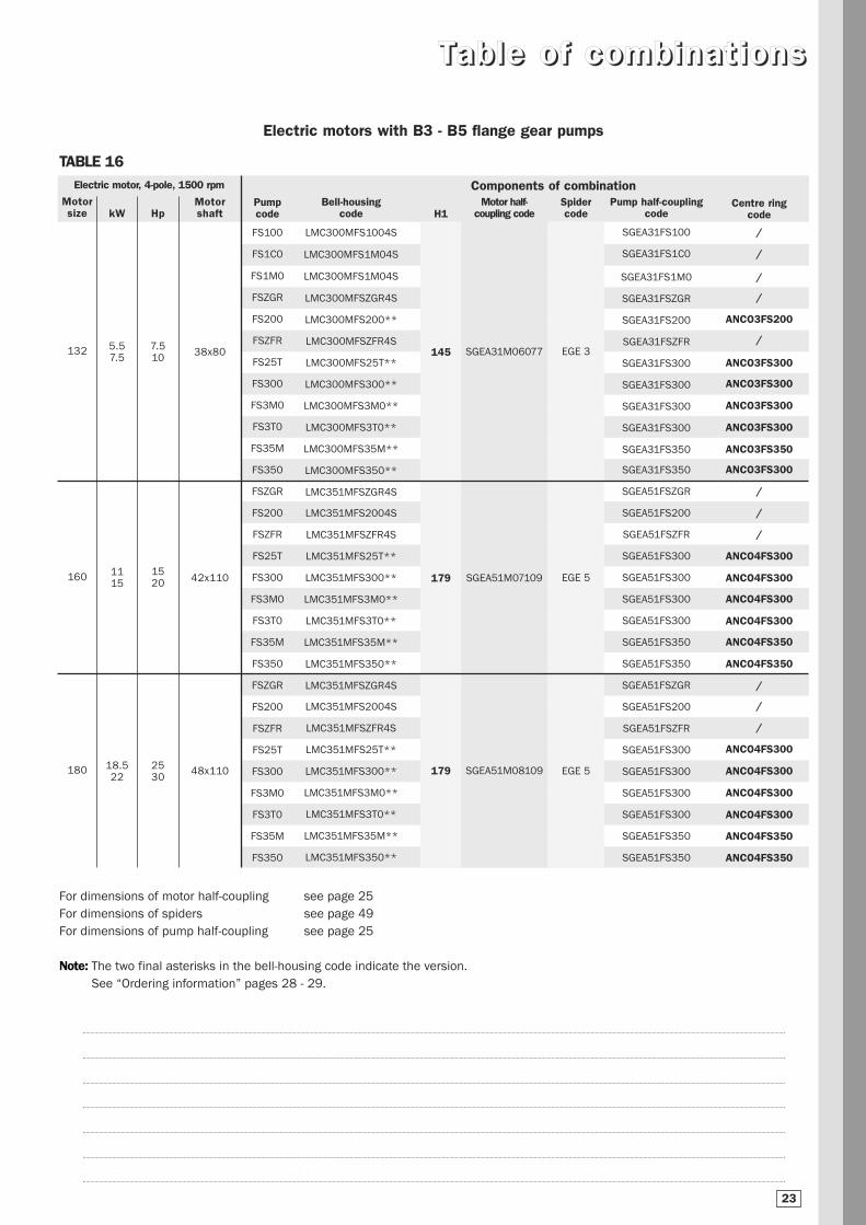
TTaabbllee ooff ccoommbbiinnaatt iioonnss
Electric motors with B3 - B5 flange gear pumps
Electric motor, 4-pole, 1500 rpm Components of combinationMotorsize
132
160
180
kW
5.57.5
1115
18.522
Hp
7.510
1520
2530
Motorshaft
38x80
42x110
48x110
Pumpcode
FS100
FS1C0
FS1M0
FSZGR
FS200
FSZFR
FS25T
FS300
FS3M0
FS3T0
FS35M
FS350
FSZGR
FS200
FSZFR
FS25T
FS300
FS3M0
FS3T0
FS35M
FS350
FSZGR
FS200
FSZFR
FS25T
FS300
FS3M0
FS3T0
FS35M
FS350
Motor half-coupling code
SGEA31M06077
SGEA51M07109
SGEA51M08109
Pump half-couplingcode
SGEA31FS100
SGEA31FS1C0
SGEA31FS1M0
SGEA31FSZGR
SGEA31FS200
SGEA31FSZFR
SGEA31FS300
SGEA31FS300
SGEA31FS300
SGEA31FS300
SGEA31FS350
SGEA31FS350
SGEA51FSZGR
SGEA51FS200
SGEA51FSZFR
SGEA51FS300
SGEA51FS300
SGEA51FS300
SGEA51FS300
SGEA51FS350
SGEA51FS350
SGEA51FSZGR
SGEA51FS200
SGEA51FSZFR
SGEA51FS300
SGEA51FS300
SGEA51FS300
SGEA51FS300
SGEA51FS350
SGEA51FS350
Spidercode
EGE 3
EGE 5
EGE 5
For dimensions of motor half-coupling see page 25
For dimensions of spiders see page 49
For dimensions of pump half-coupling see page 25
Note: The two final asterisks in the bell-housing code indicate the version.
See “Ordering information” pages 28 - 29.
TABLE 16
Centre ringcode
/
/
/
/
ANCO3FS200
/
ANCO3FS300
ANCO3FS300
ANCO3FS300
ANCO3FS300
ANCO3FS350
ANCO3FS300
/
/
/
ANCO4FS300
ANCO4FS300
ANCO4FS300
ANCO4FS300
ANCO4FS350
ANCO4FS350
/
/
/
ANCO4FS300
ANCO4FS300
ANCO4FS300
ANCO4FS300
ANCO4FS350
ANCO4FS350
Bell-housingcode
LMC300MFS1004S
LMC300MFS1M04S
LMC300MFS1M04S
LMC300MFSZGR4S
LMC300MFS200**
LMC300MFSZFR4S
LMC300MFS25T**
LMC300MFS300**
LMC300MFS3M0**
LMC300MFS3T0**
LMC300MFS35M**
LMC300MFS350**
LMC351MFSZGR4S
LMC351MFS2004S
LMC351MFSZFR4S
LMC351MFS25T**
LMC351MFS300**
LMC351MFS3M0**
LMC351MFS3T0**
LMC351MFS35M**
LMC351MFS350**
LMC351MFSZGR4S
LMC351MFS2004S
LMC351MFSZFR4S
LMC351MFS25T**
LMC351MFS300**
LMC351MFS3M0**
LMC351MFS3T0**
LMC351MFS35M**
LMC351MFS350**
H1
145
179
179
23

Electric motor, 4-pole, 1500 rpm Components of combinationMotorsize
63
71
80
90
100112
kW
0.120.18
0.250.37
0.550.75
1.11.5
2.24
Hp
0.160.25
0.350.55
0.751
1.52
35.5
Motorshaft
11x23
14x30
19x40
24x50
28x60
Pumpcode
FS05M
FS05C
FS100
FS1C0
FS1M0
FSZBR
FS05M
FS05C
FS100
FS1C0
FS1M0
FSZBR
FS05M
FS05C
FS100
FS1C0
FS1M0
FSZBR
FS200
FSZFR
FS05M
FS05C
FS100
FS1C0
FS1M0
FSZBR
FS200
FSZFR
FS05M
FS05C
FS100
FS1C0
FS1M0
FSZBR
FS200
FSZFR
Bell-housingcode
LMC090MFS05M4E
LMC090MFS05M4E
LMC090MFS1004E
LMC090MFS1M04E
LMC090MFS1M04E
LMC090MFSZBR4E
LMC105MFS05M4E
LMC105MFS05M4E
LMC105MFS1004E
LMA105MFS1C04E
LMC105MFS1M04E
LMC105MFSZBR4E
LMC120MFS05M4E
LMC120MFS05M4E
LMC120MFS1004E
LMC120MFS1M04E
LMC120MFS1M04E
LMC120MFSZFR4S
LMC121MFS2004E
LMC121MFSZFR4S
LMC141MFS05M4S
LMC141MFS05M4S
LMC141MFS100**
LMA141MFS1M0**
LMC141MFS1M0**
LMC141MFSZBR4S
LMC141MFS200**
LMC141MFSZFR4S
LMC161MFS05M4S
LMC161MFS05M4S
LMC161MFS1004S
LMC161MFS1M04S
LMC161MFS1M04S
LMC161MFSZBR4S
LMC161MFS200**
LMC161MFSZFR4S
Motor half-coupling code
SGEA01M01021
SGEA01M02028
SGEA01M03048
SGEA21M03048
SGEA01M04048
SGEA21M04048
SGEA21M05055
Pump half-coupling code
SGEA00FS05M
SGEA01FS05C
SGEA01FS100
SGEA01FS1C0
SGEA01FS1M0
SGEA01FSZBR
SGEA01FS05M
SGEA01FS05C
SGEA01FS100
SGEA01FS1C0
SGEA01FS1M0
SGEA01FSZBR
SGEA01FS05M
SGEA01FS05C
SGEA01FS100
SGEA01FS1C0
SGEA01FS1M0
SGEA01FSZBR
SGEA21FS200
SGEA21FSZFR
SGEA01FS05M
SGEA01FS05C
SGEA01FS100
SGEA01FS1C0
SGEA01FS1M0
SGEA01FSZBR
SGEA21FS200
SGEA21FSZFR
SGEA21FS05M
SGEA21FS05C
SGEA21FS100
SGEA21FS1C0
SGEA21FS1M0
SGEA21FSZBR
SGEA21FS200
SGEA21FSZFR
Note: The two final asterisks in the bell-housing code indicate the version.
See “Ordering information” pages 28 - 29.
For dimensions of motor half-coupling see page 25
For dimensions of spiders see page 49
For dimensions of pump half-coupling see page 25
TTaabbllee ooff ccoommbbiinnaatt iioonnss
Electric motors with B14 flange gear pumps
TABELLA 17
Spidercode
EGE 0
EGE 0
EGE 0
EGE 2
EGE 0
EGE 2
EGE 2
Centre ringcode
ANCA001
ANCA001
ANCO1FS100
ANCO1FS1M0
ANCO1FS1M0
/
ANCA001
ANCA001
ANCO1FS100
ANCO1FS1M0
ANCO1FS1M0
/
ANCA001
ANCA001
ANCO1FS100
ANCO1FS1M0
ANCO1FS1M0
/
ANCO2FS200
/
ANCA001
ANCA001
ANCO1FS100
ANCO1FS1M0
ANCO1FS1M0
/
ANCO2FS200
/
/
/
/
/
/
/
ANCO2FS200
/
H1
60
67
87
95
95
95
105
24
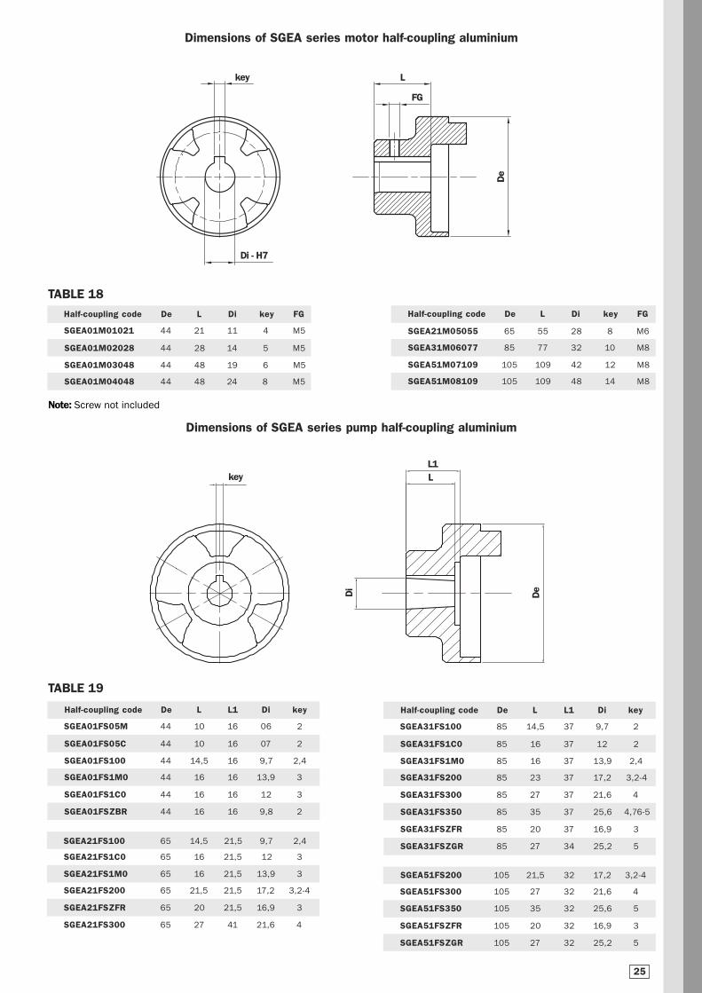
Lkey
Di - H7
Half-coupling code De L Di key FG
SGEA01M01021 44 21 11 4 M5
SGEA01M02028 44 28 14 5 M5
SGEA01M03048 44 48 19 6 M5
SGEA01M04048 44 48 24 8 M5
De
Lkey
Di
De
L1
Half-coupling code De L L1 Di key
SGEA01FS05M 44 10 16 06 2
SGEA01FS05C 44 10 16 07 2
SGEA01FS100 44 14,5 16 9,7 2,4
SGEA01FS1M0 44 16 16 13,9 3
SGEA01FS1C0 44 16 16 12 3
SGEA01FSZBR 44 16 16 9,8 2
SGEA21FS100 65 14,5 21,5 9,7 2,4
SGEA21FS1C0 65 16 21,5 12 3
SGEA21FS1M0 65 16 21,5 13,9 3
SGEA21FS200 65 21,5 21,5 17,2 3,2-4
SGEA21FSZFR 65 20 21,5 16,9 3
SGEA21FS300 65 27 41 21,6 4
Half-coupling code De L Di key FG
SGEA21M05055 65 55 28 8 M6
SGEA31M06077 85 77 32 10 M8
SGEA51M07109 105 109 42 12 M8
SGEA51M08109 105 109 48 14 M8
Half-coupling code De L L1 Di key
SGEA31FS100 85 14,5 37 9,7 2
SGEA31FS1C0 85 16 37 12 2
SGEA31FS1M0 85 16 37 13,9 2,4
SGEA31FS200 85 23 37 17,2 3,2-4
SGEA31FS300 85 27 37 21,6 4
SGEA31FS350 85 35 37 25,6 4,76-5
SGEA31FSZFR 85 20 37 16,9 3
SGEA31FSZGR 85 27 34 25,2 5
TABLE 18
Dimensions of SGEA series motor half-coupling aluminium
Dimensions of SGEA series pump half-coupling aluminium
TABLE 19
SGEA51FS200 105 21,5 32 17,2 3,2-4
SGEA51FS300 105 27 32 21,6 4
SGEA51FS350 105 35 32 25,6 5
SGEA51FSZFR 105 20 32 16,9 3
SGEA51FSZGR 105 27 32 25,2 5
FG
25
Note: Screw not included

MP Filtri OMT Hydrapp Raja KTR
New codeLMC140MFS05M**LMC140MFS05C**LMC140MFS100**LMC140MFS1C0**LMC140MFS1M0**LMC140MFSZBR**LMC160MFS05M**LMC160MFS05C**LMC160MFS100**LMC160MFS1C0**LMC160MFS1M0**LMC160MFSZBR**LMC200MFS05M**LMC200MFS05C**LMC200MFS100**LMC200MFS1C0**LMC200MFS1M0**LMC200MFSZBR**LMC201MFS200**LMC201MFSZBR**LMC250MFS100**LMC250MFS1C0**LMC250MFS1M0**LMC250MFSZBR**LMC250MFS200**LMC250MFSZFR**LMC250MFS25T**LMC250MFS300**LMC250MFS3M0**LMC250MFS3T0**LMC300MFS100**LMC300MFS1C0**LMC300MFS1M0**LMC300MFSZBR**LMC300MFS200**LMC300MFFSZR**LMC300MFS25T**LMC300MFS300**LMC300MFS3M0**LMC300MFS3T0**LMC300MFS35M**LMC300MFS350**LMC351MFSZGR**LMC351MFS200**LMC351MFFSZR**LMC351MFS25T**LMC351MFS300**LMC351MFS3M0**LMC351MFS3T0**LMC351MFS35M**LMC351MFS350**LMC351MFSZGR**LMC351MFS200**LMC351MFFSZR**LMC351MFS25T**LMC351MFS300**LMC351MFS3M0**LMC351MFS3T0**LMC351MFS35M**
Note: The above table is guideline only.
All bell-housings of the MP Filtri range can be considered equivalent to the counterpart brands listed.
For further information, contact the MP Filtri Technical and Sales Department.
CCoommppaarraatt iivvee ttaabbllee -- BBeell ll --hhoouuss iinngg
Old codeLMB140A060A001LMB140A060A001LMB140A060A002LMB140A060A003LMB140A060A003LMB140A060S013LMB160A067A001LMB160A067A001LMB160A067A002
LMB160A067A003*LMB160A067A003LMB160A067S013LMB200A087A001
LMB200A087A001*LMB200A087A002LMB200A087A003LMB200A087A003LMB200A087S013LMB200A095C004LMB200A098S014LMB250A109C002LMB250A109C003LMB250A109C003LMB250A109S013LMB250A109C004LMB250A109S014LMB250A126D005LMB250A126D006LMB250A126D007LMB250A126D006
////
LMB300A130D004LMB300A130S014LMB300A147D005LMB300A147D005LMB300A147D005LMB300A147D006
///
LMB350A160D004LMB350A160S014LMB350A179F005LMB350A179F005LMB350A179F005LMB350A179F006
///
LMB350A160D004LMB350A160S014LMB350A179F005LMB350A179F005LMB350A179F005LMB350A179F006
/
26
Code Code Code C odeLS140 / / /
LS140 / / /
LS141 / L45 /
LS142 / / /
LS142 / B45 /
LBS18 / Bo45 /
LS160 HL1 H9 PL160/1/...
LS160 HL2 H9 PL160/1/...
LS161 HL2 L9 PL160/1/...
LS162 HL3 L9 PL160/1/...
LS162 HL4 B9 PL160/1/...
LBS19 HLB1 Bo9 PL160/1/...
LS210 HL4L H2 PL200/1/...
LS210 HL4L H2 PL200/1/...
LS211 HL5L L2 PL200/1/...
LS212 HL6L B2 PL200/1/...
LS212 HL6L B2 PL200/1/...
LBS28 HLB3L Bo2 PL200/1/...
LS203 HL7SL L7/4 PL200/2/...
LS203 HLB12SL Bo7 PL200/2/...
LS250 HL8/1L L6/3 PL250/1/...
LS251 HL8L B5 PL250/1/...
LS251 HL8L B5 PL250/1/...
LBS22 HLB13L Bo5 PL250/1/...
LS252 HL9L L6/3 PL250/1/...
LBS23 HLB17L Bo6 PL250/1/...
LS254 HL11 L4/3 PL250/7/...
LBS25 HL11 L4/3 PL250/7/...
LS256 HL11 L4/3 PL250/7/...
LS257 HL11T L34 PL250/7/...
LS210 / / PL300/2/...
LS211 / / PL300/2/...
LS311 / / PL300/2/...
/ / / PL300/2/...
LS300 HL12 L13 PL300/2/...
LBS26 HLB22 Bo13 PL300/2/...
LS301 HL13 L12 PL300/2/...
LS302 HL13 L12 PL300/2/...
LS303 HL13 L12 PL300/2/...
LS304 HL13T L14 PL300/2/...
LS305 / L16 PL300/2/...
LS306 HLB28 L15 PL300/2/...
LBS27 HL15 Bo14 PL350/2/...
LS350 HLB27 L17 PL350/2/...
LBS31 / Bo18 PL350/2/...
LS351 / L18 PL350/2/...
LS352 / L18 PL350/2/...
LS353 / L18 PL350/2/...
LS354 / L19 PL350/2/...
LSE355 / L21 PL350/2/...
LSE356 / L20 PL350/2/...
LBS32 / Bo19 PL350/2/...
LS350 HL15 L17 PL350/2/...
LBS31 HLB27 Bo18 PL350/2/...
LS351 / L18 PL350/2/...
LS352 / L18 PL350/2/...
LS353 / L18 PL350/2/...
LS354 / L19 PL350/2/...
LSE355 / L21 PL350/2/...

CCoommppaarraatt iivvee ttaabbllee -- HHaall ff -- ccoouuppll iinngg
MP Filtri OMT
Note: The above table is guideline only.
Not all half-couplings are fully interchangeable.
For further information, contact the MP Filtri Technical and Sales Department.
New code Old code
SGEA01FS05M SGEA00B01018
SGEA01FS05C SGEA00B02018
SGEA01FS100 SGEA00B07018
SGEA01FS1C0 SGEA00B03014
SGEA01FS1M0 SGEA00B06016
SGEA01FSZBR SGEA00B08014
SGEA21FS100 SGEA20B07018
SGEA21FS1C0 SGEA20B03024
SGEA21FS1M0 SGEA20B06024
SGEA21FSZBR SGEA20B08024
SGEA21FS200 SGEA20B100242A
SGEA21FSZFR SGEA20B13024
SGEA21FS25T SGEA20B16041
SGEA31FS100 SGEA30B07022
SGEA31FS1C0 /
SGEA31FS1M0 SGEA30B06021
SGEA31FSZBR /
SGEA31FS200 SGEA30B100222A
SGEA31FSZFR SGEA30B13020
SGEA31FS300 SGEA30B16038
SGEA31FS350 SGEA30B180382B
SGEA51FSZGR SGEA50B17034
SGEA51FS200 /
SGEA51FSZFR SGEA50B13032
SGEA51FS300 SGEA50B16032
SGEA51FS350 SGEA50B180342B
SGEA51FS400 SGEA50B210462C
27
Code
ND48P05M
ND48P05GT
ND48PU1P
ND48P1C
ND48PIM
ND48PZB
ND65PU1P
ND65P1C
ND65P1M
ND65PZB
ND65P2
ND65PZF
ND65Q3U
ND86PU1P
ND86P1C
ND86P1M
/
ND86P2
ND86PZF
ND86P3U
/
/
/
ND108PZF
ND108P3U
ND108Q35
/

AKG1 2 3Coupling kit
Example: AKG 02 FS100 Z
OOrrddeerr iinngg iinn ffoorrmmaatt iioonn AAKKAA
3 - Product revision code
Z
Note: For customization features other than those indicated on this page, contact the Technical and Sales Department
Details contained in this publication are guideline only. MP Filtri reserves the right to make changes at any given time to the models described, whether for
technical or marketing reasons. The colours of products are purely indicative. Reproduction forbidden. All rights reserved.
2 - Pump identitification code
FS200 See table 14 page 21
AKA1 2 3
Complete coupling kit
Example: AKA 02 FS100 Z 4E
OOrrddeerr iinngg iinn ffoorrmmaatt iioonn AAKKGG
3 - Product revision code
Z
1 - Sizes
02 Size 63 B3-B5
03 Size 71 B3-B5
04 Size 80 B3-B5
05 Size 90 B3-B5
07 Size 100/112 B3-B5
11 Size 132 B3-B5
12 Size 160 B3-B5
13 Size 180 B3-B5
4
See page 20
43 Size 63 B14
44 Size 71 B14
45 Size 80 B14
46 Size 90 B14
48 Size 100/112 B14
2 - Pump identitification code
FS200 See table 14 page 21
1 - Sizes
02 Size 63 B3-B5
03 Size 71 B3-B5
04 Size 80 B3-B5
05 Size 90 B3-B5
07 Size 100/112 B3-B5
11 Size 132 B3-B5
12 Size 160 B3-B5
13 Size 180 B3-B5
43 Size 63 B14
44 Size 71 B14
45 Size 80 B14
46 Size 90 B14
48 Size 100/112 B14
28
4 - Versions
4S
4E
8S
8E

LMC1 2 3 4Monobloc bell-housing
Example: LMC 140 M FS200 4E DI
OOrrddeerr iinngg iinn ffoorrmmaatt iioonn LLMMCC5
4 - Option
4S
4E
8S
8E
4 through holes + 4 threaded holes,motor interface without coupling removal ring
4 through holes + 4 threaded holes,motor interface with coupling removal ring
8 through holes,motor interface without coupling removal ring
8 through holes,motor interface with coupling removal ring
Note: For customization features other than those indicated on this page, contact the Technical and Sales Department
Details contained in this publication are guideline only. MP Filtri reserves the right to make changes at any given time to the models described, whether for
technical or marketing reasons. The colours of products are purely indicative. Reproduction forbidden. All rights reserved.
1 - Sizes
140
141
160
161
200
201
250
300
351
2 - Product revision code
M
3 - Pump flange identification code
FS200 See table 14 page 21
5 - Option
DI Drain hole + inspection hole
AN Black anodized finish
SA Motor interface with clearance holes
Pxx Customer specification
N.B. Bell-housings with DI options are supplied complete with threaded closure plug
29

DATA REQUIRED
Electric motor power/motor size
Manufacturer and pump type
TO VERIFY:
1 - Pump and motor shaft dimensions (see page 69)
2 - Shaft and flange pump (see pump data sheet)
Example:
- Electric motor 2 kW - 4 poles - Motor size 110/112
- Atos pump code PFE31 - Shaft 1
AA gguuiiddee ttoo sseelleecctt tthhee ccoorr rr eecctt bbee ll ll --hhoouuss iinngg aanndd ddrr ii vvee ccoouupp ll iinngg ccoommppoonneennttss
8
250 4,76
60 57,5
9,5
28 19,05
Nr. 2x11
Ø 82,55
Ø 106,4
Bell-Housing's length calculation
• H= 60 + 18 + 57,5 = 135,5 mm (18= Sp spider - see page 49)
• Choose type of bell-housing (LMC - LMS)
- For LMC see tab. 3 at page 11
- For LMS see tab. 21 at page 32
- For MODUL 2/3 see at page 36
Note: The length of bell-housing must be ≥ than the length calculated (135,5 mm)
Case A - solution with LMC bell-housing
Tab. 3 at page 11 - for electric motor 2kW LMC 250
LMC 250 bell-housing with height ≥ 135,5 - LMC250AFSQ
• The bell-housing code must be completed with drilling pump code (see tab. 34 at page 47)
For the specific case C= 101,6 - Nr. 2 holes M10: Code drilling 070
• Definitive bell-housing code LMC250AFSQ070
Case B - solution with LMS bell-housing
Tab. 21 at page 32 - for electric motor 2kW LMS 250
LMS 250 bell-housing with heigh ≥ 135,5 - LMS250AFSQ
• The bell-housing code must be completed with drilling pump code (see tab. 34 at page 47)
For the specific case C= 101,6 - Nr. 2 holes M10: Code for. 070
• Definitive bell-housing code LMS250AFSQ070
Electric motor’s dimension Pump’s dimensions
2
Choose coupling
• Motor half-coupling (see tab. 37 at page 50)
- For electric motor GR 100/112, the half-coupling is SGEA21M05060
• Spider (see tab. 35 - 36 at page 49)
- For SGEA21, EGE2 - EGE2RR
(choose spider material on the base of the application, oil, temperature and cycle machine, etc.)
• Pump half-coupling
- Choose the drilling code tab. 43 - 44 at page 53 for shaft 19,05 - Ch. 4,76 - code: G01
- Half-coupling length = L BH lenght – THK Spider – THK Spigot
138 mm - 60 - 18 - 9,5= 50,5 mm
- Choose the half-coupling’s length on tab. 38 at page 50 ≤ 50,5 mm.
- Availabe length for SGEA21= 50 mm
- Code half-coupling code: SGEA21G01050
Software for automatic calculation available on the web sitewww.mpfiltri.com - tools - software
Note: For multi pumps we recommend to use a specific support on the base of the pump’s dimensions and weight.
3

HHaall ff --ccoouuppll ii nngg SSGGEE****** sseerr iieess
The half-couplings series SGE*** allow secure transmission between the electric motor and the driven side; they are able to absorb
shocks and vibration, in addition to compensating radial misalignment, angular and axial.
The assembly of the couplings can be horizontal/vertical, withstanding vibration and load reversals.
The complete range of couplings are extrapolated from the on-line software, with a length equal than the shaft on which must be
mounted and they are completed with grub screw for fixing located on the key.
Available for cilindrical shaft with metric and imperial dimensions as well for splined shafts as per specification DIN, ISO and SAE.
Admissible misalignment radial, angular and axial
Half coupling
SGE * 01
SGE * 21
SGE * 31
SGE * 40
SGE * 51
SGE * 60
SGE * 80
SGE * 90
R (mm)
0,5
1,0
1,0
1,0
1,5
1,5
2,0
2,0
Max admissible radialmisalignment
Half coupling
SGE * 01
SGE * 21
SGE * 31
SGE * 40
SGE * 51
SGE * 60
SGE * 80
SGE * 90
b (°)
1,5°
Half coupling
SGE * 01
SGE * 21
SGE * 31
SGE * 40
SGE * 51
SGE * 60
SGE * 80
SGE * 90
A (mm)
2,0
2,5
3,0
3,5
3,5
3,5
4,0
5,0
Max admissible angularmisalignment
Max admissible angular misalignment
CAD 3D FEM (calculation)
Drawings 3D available on website www.mpfiltri.com at section TOOLS/2D-3D COMPONENTS
4
Normative ATEX 94/9/CE
Half-couplings SGE*** series are available to use in hazardous area.
The couplings are certified according to ATEX 94/9/CE (ATEX 95).
Category certified 2G - area 1 and 2.
Other information available on our web site “www.mpfiltri.com”.
MP Filtri couplings are developed with:
The half-couplings SGE*** series are in conformity to normative DIN 740/2.
The max torque to transmit is always less than the max torque that the coupling can transmit.
Examples verification of the coupling
SSiizz iinngg ooff hhaall ff --ccoouuppll ii nngg
Determine the size of the coupling according to the type of installation and application envisaged, on the basis of the following
formulas and tables:
Nominal and maximum torque values are referred to couplings assembled with standard flexible spiders of the
EGE** series (see page 49).
Where higher torques are to be transmitted, use flexible spiders of the EGE**RR series (see page 49).
Torque transmitted by electric motor:
Mt: 9560 x kW / rpm = Nm
Me > Mt x S = Nm
Where:
Mt: Torque transmitted by electric motor
Me: Torque transmitted by coupling (see table 14)
kW: Power of electric motor
Rpm: Revolutions per minute of electric motor
S: Service factor (see table 14)
Example Electric motor, 4 pole - 4 kW
hydraulic pump, uniform load, low operating pressure
Mt: 9560 x 4 / 1500 = 25.45 Nm
Me > 25.49 x 1.3 = 33 Nm
Half-coupling SGEA21 meets the above requirement.
Select the half-coupling of the calculated size from the motor half-couplings table.
Small pumps, uniform load, low operating pressurese.g. rotary action machine tools - 5/8 work cycles per hour
1.3
Small pumps, uniform load, high working pressurese.g. lifting equipment - 120-150 work cycles per hour
1.5
Pumps, non-uniform loade.g. lifting equipment - 280-300 work cycles per hour
1.7
Half-coupling type External diameter Nominal torque Maximum transmissible torquemm Me - Nm Me - Nm
SGEA01 43 15 20
SGEA21 68 160 190
SGEA31 85 340 380
SGEA51 109,5 550 620
Note: When selecting the coupling, remember that for pumps with splined shaft, only cast iron couplings of the
SGEG series can be used.
TABLE 2
TABLE 1
SGEG01 40 20 30
SGEG30 80 400 450
SGEG40 95 550 620
SGEG60 120 760 850
SGEG80 160 2200 2500
SGEG90 200 5500 6100
ALU
MIN
IUM
CAST
IRO
N
SGES40 95 550 620
SGES60 120 760 850
SGES80 160 2200 2500STEE
L
5
Noise is a particularly pervasive problem so much so that there have been statutory regulations in place now for some years, designed to limit harmful occupational exposure.Many of the machines used in industry today are equipped with oil-hydraulic systems, which happen to be a major source of noise.
1. Theory and definition of noise
From a health and hygiene standpoint, noise can be defined as an unpleasant and undesirable sound, or an unpleasant and
annoying or intolerable auditory sensation (noise being any sound phenomena that may be accompanied by sensations of
disturbance and pain). By definition, acoustic phenomena are oscillatory in character, propagated in a flexible medium
and causing pressure variations at the points, and the areas adjacent to those points, through which they pass.
2. Sound
Technically considered, certain elements must be present simultaneously for acoustic phenomena to occur:
• Sound source
• Transmission medium
• Receiver
NNooiissee
The electric motor and the pump, together with the drive coupling, are the SOURCE OF THE NOISE.
The Bell-housing is the noise transmission medium.
Depending on whether the monobloc bell-housing is a rigid or low noise type, there will be variations in the flexible
properties of the transmission medium.
The acoustic phenomena are dissimilar in the two cases, given the differences in pressure variation
and particle displacement.
RECEIVER- Human ear- Sound level meter
Motor and pump unit
Electric motor
Pump
Bell-housing
6
AAsssseemmbbll yy ooff mmoottoorr aanndd ppuummpp uunnii tt
As mentioned in the presentation, low noise bell-housing will help to attenuate the transmission of vibrations and the emission of noise generated by the system.Self-evidently, however, the mere adoption of a low noise bell-housing will achieve little unless the motor and pump are correctly installed on the machine, or on the tank of the hydralic power unit.
• Should be followed in order to achieve best possible results and correct installation:
1.Motor and pump unit mounted horizontally on oil tank lid
• The suction pipe attached to the pump must be rigid,
and fitted using a resilient bulkhead flange of the
FTA series, which helps to cushion the vibrations
propagated between the pipe and the tank lid.
If pipes need to be bent, the radius of
curvature must be at least 3 times the pipe diameter.
Do not use elbow fittings, as these will
significantly increase pressure losses.
• The pressure pipeline of the pump must be
flexible, and long enough to include bends
with the minimum radius of curvature recommended
by the manufacturer for the specified operating pressure.
• The return pipeline running from the service to the
filter must be flexible.
Where oil is returned directly to the
tank of the hydraulic power unit through a rigid pipe,
it is advisable to use a resilient bulkhead flange
of the FTR series, which helps to
cushion the vibrations propagated between the pipe
and the tank lid.
• Anti-vibration devices (resilient mounts
or damping rods) must be located under the feet of the
electric motor or the PDM foot brackets,
depending on the mounting position of the motor.
• The lids of hydraulic oil tanks must be sturdy enough
to support the load they carry.
2.Motor and pump unit mounted horizontally on machine
• As a matter of good practice, the oil tank and motor-pump
unit should be mounted on a single supporting frame
of strength sufficient to support the load.
• If the hydraulic system is fitted with a side-mounted filter,
the suction pipeline to the pump must be flexible, and
long enough to include bends with the minimum radius of
curvature recommended by the manufacturer.
• If the suction filter is not side mounted, the pipeline
should be rigid and installed in conjunction with a
compensating coupling.
• The pressure pipeline of the pump must be flexible, and
long enough to include bends with the minimum radius of
curvature recommended by the manufacturer
for the specified operating pressure.
• The return pipeline running from the service to the
filter must be flexible.
Where oil is returned directly to the tank of the hydraulic
power unit through a rigid pipe, it is advisable to use a
resilient bulkhead flange of the FTR series, which helps to
cushion the vibrations propagated between the pipe
and the tank lid.
• Anti-vibration devices (resilient mounts or damping rods)
must be located under the feet of the electric motor
or the PDM foot brackets, depending
on the mounting position of the motor.
Note: The above guidelines are indicative only, and subordinate to the solutions adopted ultimately by design engineers.
In conclusion: For best results, in any event, the motor-and-pump unit should be incorporated into the hydraulic system in such a
way that no one component is rigidly associated with another, resulting in the propagation of vibration, and
consequently noise.
7

TTaabbllee ooff ssuummmmaarr yy MMOODDUULL 22//33
BM
T30
0B
MT3
50
Kit
of
asse
mbl
y K
VG
5 (
Q.t
y 1
) +
Kit
of as
sem
bly
KV
G1
(Q
.ty
1)
Ø 1
90
Ø 8
5
AR
*
FR1
*
MO
DU
L 2
BM
T35
0B
MT4
00
BM
T45
0
Kit
of as
sem
bly
KV
G5
/7
(Q
.ty
2)
Ø 1
90
Ø 2
88
Ø 1
40
Ø 2
88
AD
*
FP5
FP6
FP7
BM
T550
BM
T660
BM
T800
Kit
of as
sem
bly
KVG
6/7 (
Q.t
y 1)
Ø 2
88
FP6
FP7
(BA
D8
00
O
NLY
FP
7)
5.5
- 7.5
kW
7.5
- 10.2
Hp
Siz
e 225 -
D.4
50
11 -
22
15 -
30
Hp
Siz
e 160
/1
80
D.3
50
30
40
.80
Hp
Siz
e 2
00
- D
.35
0
37
- 4
5
50
.32
- 6
1.2
Hp
Siz
e 2
25
- D
.45
0
55
- 9
0
75
- 1
25
Hp
Siz
e 2
50
/2
80
D.5
50
11
0 -
20
0
15
0 -
27
2 H
p
Siz
e 3
15
- D
.66
0
25
0 -
40
0
34
0 -
54
4 H
p
Siz
e 3
55
/4
00
D.8
00
5.5
- 7.5
kW
7.5
- 10.2
Hp
Siz
e 225 -
D.4
50
11 -
22
15 -
30
Hp
Siz
e 160
/1
80
D.3
50
30
40
.80
Hp
Siz
e 2
00
- D
.35
0
37
- 4
5
50
.32
- 6
1.2
Hp
Siz
e 2
25
- D
.45
0
55
- 9
0
75
- 1
25
Hp
Siz
e 2
50
/2
80
D.5
50
11
0 -
20
0
15
0 -
27
2 H
p
Siz
e 3
15
- D
.66
0
25
0 -
40
0
34
0 -
54
4 H
p
Siz
e 3
55
/4
00
D.8
00
MO
DU
L 3
8
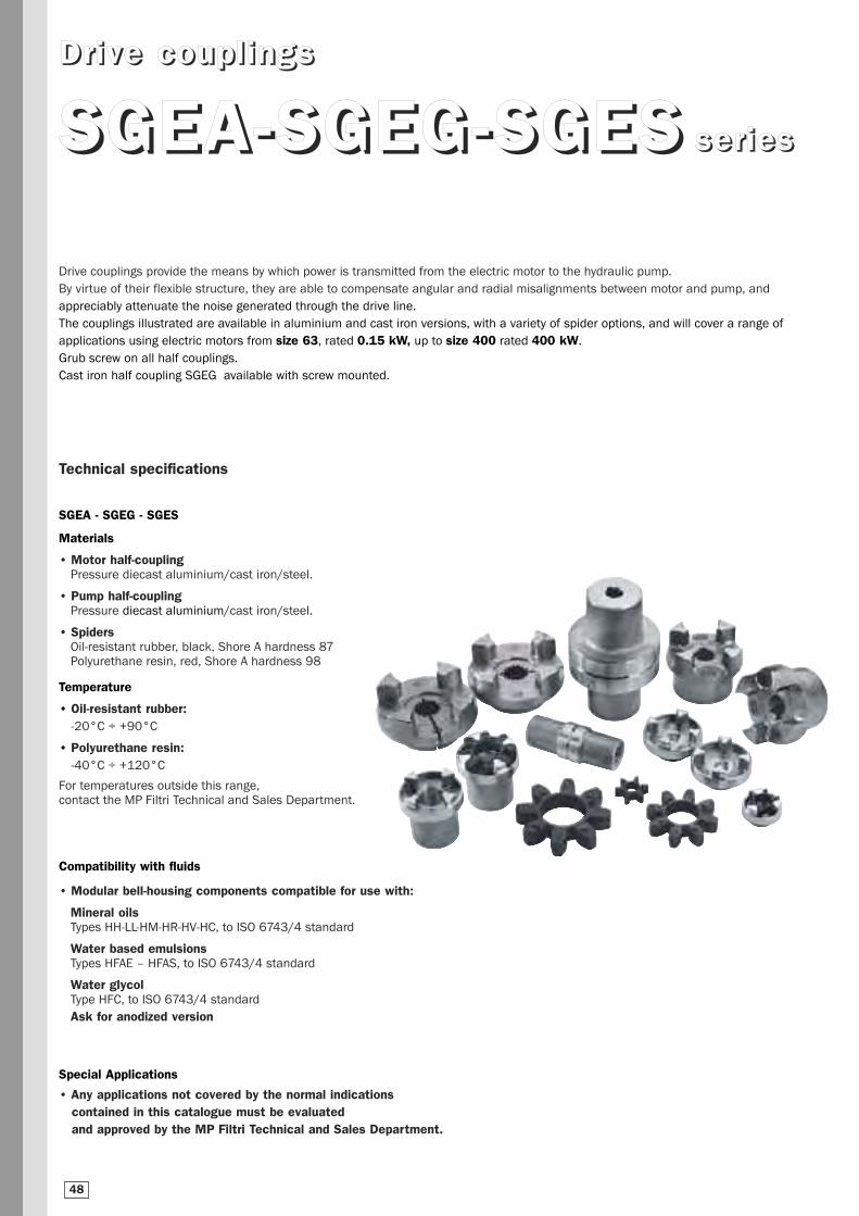
DDrr iivvee ccoouuppll iinnggss
SSGGEEAA--SSGGEEGG--SSGGEESS sseerr iieess
Drive couplings provide the means by which power is transmitted from the electric motor to the hydraulic pump.
By virtue of their flexible structure, they are able to compensate angular and radial misalignments between motor and pump, and
appreciably attenuate the noise generated through the drive line.
The couplings illustrated are available in aluminium and cast iron versions, with a variety of spider options, and will cover a range of
applications using electric motors from size 63, rated 0.15 kW, up to size 400 rated 400 kW.
Grub screw on all half couplings.
Cast iron half coupling SGEG available with screw mounted.
Technical specifications
SGEA - SGEG - SGES
Materials
• Motor half-couplingPressure diecast aluminium/cast iron/steel.
• Pump half-couplingPressure diecast aluminium/cast iron/steel.
• SpidersOil-resistant rubber, black, Shore A hardness 87Polyurethane resin, red, Shore A hardness 98
Temperature
• Oil-resistant rubber:-20°C ÷ +90°C
• Polyurethane resin:-40°C ÷ +120°C
For temperatures outside this range,contact the MP Filtri Technical and Sales Department.
Compatibility with fluids
• Modular bell-housing components compatible for use with:
Mineral oilsTypes HH-LL-HM-HR-HV-HC, to ISO 6743/4 standard
Water based emulsionsTypes HFAE – HFAS, to ISO 6743/4 standard
Water glycolType HFC, to ISO 6743/4 standard
Ask for anodized version
Special Applications
• Any applications not covered by the normal indications contained in this catalogue must be evaluated and approved by the MP Filtri Technical and Sales Department.
48
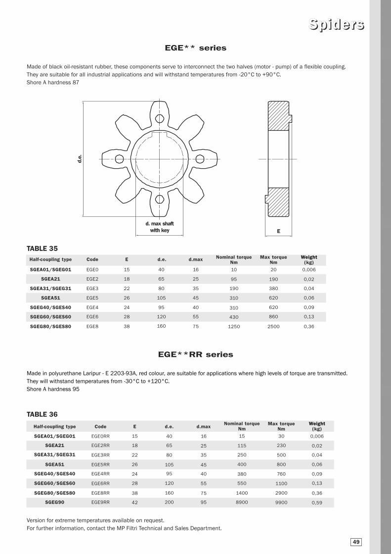
SSppiiddeerrss
Made of black oil-resistant rubber, these components serve to interconnect the two halves (motor - pump) of a flexible coupling.
They are suitable for all industrial applications and will withstand temperatures from -20°C to +90°C.
Shore A hardness 87
EGE** series
Made in polyurethane Laripur - E 2203-93A, red colour, are suitable for applications where high levels of torque are transmitted.
They will withstand temperatures from -30°C to +120°C.
Shore A hardness 95
EGE**RR series
Version for extreme temperatures available on request.
For further information, contact the MP Filtri Technical and Sales Department.
Half-coupling type
SGEA01/SGEG01
SGEA21
SGEA31/SGEG31
SGEA51
SGEG40/SGES40
SGEG60 /SGES60
SGEG80/SGES80
Code
EGE0
EGE2
EGE3
EGE5
EGE4
EGE6
EGE8
E
15
18
22
26
24
28
38
d.e.
40
65
80
105
95
120
160
d.max
16
25
35
45
40
55
75
Nominal torqueNm
10
95
190
310
310
430
1250
Max torqueNm
20
190
380
620
620
860
2500
Half-coupling type
SGEA01/SGEG01
SGEA21
SGEA31/SGEG31
SGEA51
SGEG40/SGES40
SGEG60 /SGES60
SGEG80/SGES80
SGEG90
Code
EGE0RR
EGE2RR
EGE3RR
EGE5RR
EGE4RR
EGE6RR
EGE8RR
EGE9RR
E
15
18
22
26
24
28
38
42
d.e.
40
65
80
105
95
120
160
200
d.max
16
25
35
45
40
55
75
95
Nominal torqueNm
15
115
250
400
380
550
1400
8900
Max torqueNm
30
230
500
800
760
1100
2900
9900
d.e.
Ed. max shaft
with key
TABLE 35
TABLE 36
Weight(kg)
0,006
0,02
0,04
0,06
0,09
0,13
0,36
Weight(kg)
0,006
0,02
0,04
0,06
0,09
0,13
0,36
0,59
49
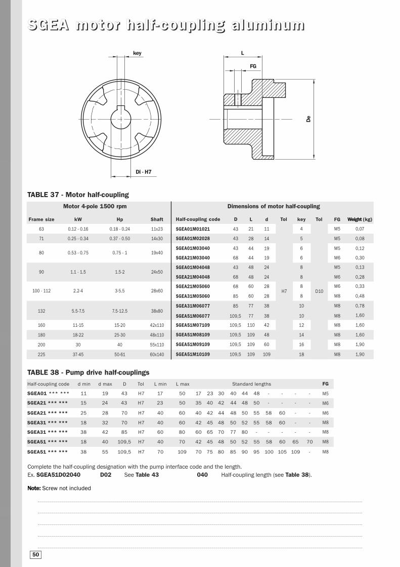
SSGGEEAA mmoottoorr hhaa ll ff --ccoouuppll iinngg aalluummiinnuumm
Dimensions of motor half-coupling
Half-coupling code D
SGEA01M01021 43
SGEA01M02028 43
SGEA01M03040 43
SGEA21M03040 68
SGEA01M04048 43
SGEA21M04048 68
SGEA21M05060 68
SGEA31M05060 85
SGEA31M06077 85
SGEA51M06077 109,5
SGEA51M07109 109,5
SGEA51M08109 109,5
SGEA51M09109 109,5
SGEA51M10109 109,5
L
21
28
44
44
48
48
60
60
77
77
110
109
109
109
d
11
14
19
19
24
24
28
28
38
38
42
48
60
109
key
4
5
6
6
8
8
8
8
10
10
12
14
16
18
Tol
D10
Weight (kg)
0,07
0,08
0,12
0,30
0,13
0,28
0,33
0,48
0,78
1,60
1,60
1,60
1,90
1,90
Motor 4-pole 1500 rpm
TABLE 37 - Motor half-coupling
Lkey
Di - H7
De
FG
Complete the half-coupling designation with the pump interface code and the length.
Ex. SGEA51D02040 D02 See Table 43 040 Half-coupling length (see Table 38).
TABLE 38 - Pump drive half-couplings
Half-coupling code d min d max D Tol L min L max Standard lengths
SGEA01 *** *** 11 19 43 H7 17 50 17 23 30 40 44 48 - - - -
SGEA21 *** *** 15 24 43 H7 23 50 35 40 42 44 48 50 - - - -
SGEA21 *** *** 25 28 70 H7 40 60 40 42 44 48 50 55 58 60 - -
SGEA31 *** *** 18 32 70 H7 40 60 42 45 48 50 52 55 58 60 - -
SGEA31 *** *** 38 42 85 H7 60 80 60 65 70 77 80 - - - - -
SGEA51 *** *** 18 40 109,5 H7 40 70 42 45 48 50 52 55 58 60 65 70
SGEA51 *** *** 38 55 109,5 H7 70 109 70 75 80 85 90 95 100 105 109 -
FG
M5
M5
M5
M6
M5
M6
M6
M8
M8
M8
M8
M8
M8
M8
FG
M5
M6
M6
M8
M8
M8
M8
50
Note: Screw not included
Tol
H7
Frame size kW Hp Shaft
63 0.12 - 0.16 0.18 - 0.24 11x23
71 0.25 - 0.34 0.37 - 0.50 14x30
80 0.53 - 0.75 0.75 - 1 19x40
90 1.1 - 1.5 1.5-2 24x50
100 - 112 2.2-4 3-5.5 28x60
132 5.5-7.5 7.5-12.5 38x80
160 11-15 15-20 42x110
180 18-22 25-30 48x110
200 30 40 55x110
225 37-45 50-61 60x140
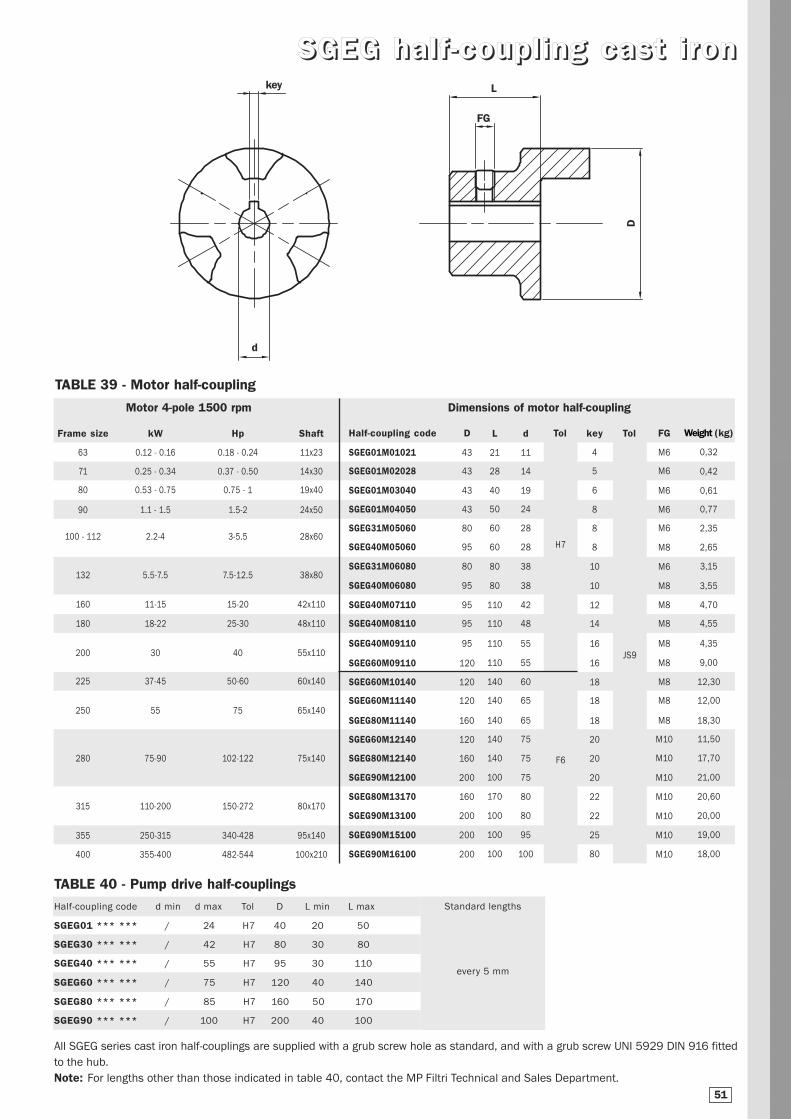
SSGGEEGG hhaall ff --ccoouuppll iinngg ccaasstt ii rr oonnL
d
key
D
Dimensions of motor half-couplingMotor 4-pole 1500 rpm
TABLE 39 - Motor half-coupling
Half-coupling code D
SGEG01M01021 43
SGEG01M02028 43
SGEG01M03040 43
SGEG01M04050 43
SGEG31M05060 80
SGEG40M05060 95
SGEG31M06080 80
SGEG40M06080 95
SGEG40M07110 95
SGEG40M08110 95
SGEG40M09110 95
SGEG60M09110 120
SGEG60M10140 120
SGEG60M11140 120
SGEG80M11140 160
SGEG60M12140 120
SGEG80M12140 160
SGEG90M12100 200
SGEG80M13170 160
SGEG90M13100 200
SGEG90M15100 200
SGEG90M16100 200
Weight (kg)
0,32
0,42
0,61
0,77
2,35
2,65
3,15
3,55
4,70
4,55
4,35
9,00
12,30
12,00
18,30
11,50
17,70
21,00
20,60
20,00
19,00
18,00
Frame size kW Hp Shaft
63 0.12 - 0.16 0.18 - 0.24 11x23
71 0.25 - 0.34 0.37 - 0.50 14x30
80 0.53 - 0.75 0.75 - 1 19x40
90 1.1 - 1.5 1.5-2 24x50
100 - 112 2.2-4 3-5.5 28x60
132 5.5-7.5 7.5-12.5 38x80
160 11-15 15-20 42x110
180 18-22 25-30 48x110
200 30 40 55x110
225 37-45 50-60 60x140
250 55 75 65x140
280 75-90 102-122 75x140
315 110-200 150-272 80x170
355 250-315 340-428 95x140
400 355-400 482-544 100x210
FG
M6
M6
M6
M6
M6
M8
M6
M8
M8
M8
M8
M8
M8
M8
M8
M10
M10
M10
M10
M10
M10
M10
key
4
5
6
8
8
8
10
10
12
14
16
16
18
18
18
20
20
20
22
22
25
80
Tol
JS9
Tol
H7
F6
d
11
14
19
24
28
28
38
38
42
48
55
55
60
65
65
75
75
75
80
80
95
100
L
21
28
40
50
60
60
80
80
110
110
110
110
140
140
140
140
140
100
170
100
100
100
FG
All SGEG series cast iron half-couplings are supplied with a grub screw hole as standard, and with a grub screw UNI 5929 DIN 916 fitted
to the hub.
Note: For lengths other than those indicated in table 40, contact the MP Filtri Technical and Sales Department.
Half-coupling code d min d max Tol D L min L max
SGEG01 *** *** / 24 H7 40 20 50
SGEG30 *** *** / 42 H7 80 30 80
SGEG40 *** *** / 55 H7 95 30 110
SGEG60 *** *** / 75 H7 120 40 140
SGEG80 *** *** / 85 H7 160 50 170
SGEG90 *** *** / 100 H7 200 40 100
TABLE 40 - Pump drive half-couplings
51
Standard lengths
every 5 mm
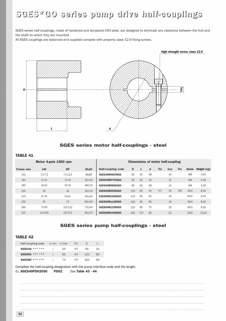
SSGGEESS**GGOO sseerr iieess ppuummpp ddrr iivvee hhaall ff --ccoouuppll iinnggss
SGES series half-couplings, made of hardened and tempered C40 steel, are designed to eliminate any clearance between the hub and
the shaft on which they are mounted.
All SGES couplings are balanced and supplied compete with property class 12.9 fixing screws.
High strength screw, class 12.9
L d
key
D
Motor 4-pole 1500 rpm
TABLE 41
Dimensions of motor half-coupling
Frame size kW HP Shaft
132 5.5-7.5 7.5-12.5 38x80
160 11-15 15-20 42x110
180 18-22 25-30 48x110
200 30 40 55x110
225 37-45 50-61 60x140
250 55 75 65x140
280 75-90 102-122 75x140
315 110-200 150-272 80x170
Half-coupling code D
SGES40M06050G0 95
SGES40M07065G0 95
SGES40M08065G0 95
SGES60M09085G0 120
SGES60M10085G0 120
SGES60M11085G0 120
SGES60M12085G0 120
SGES80M13085G0 160
L
50
65
65
85
85
85
85
170
d
38
42
48
55
60
65
75
80
key
10
12
14
16
18
18
20
22
Tol
JS9
Screw
M8
M8
M8
M10
M10
M10
M10
M10
Tol
H7
Half-coupling code d min d max Tol D L
SGES40 *** *** / 55 H7 95 35
SGES60 *** *** / 65 H7 120 65
SGES80 *** *** / 75 H7 160 85
TABLE 42
Complete the half-coupling designation with the pump interface code and the length.
Ex. SGES40PD02050 PD02 See Table 43 - 44
SGES series pump half-couplings - steel
SGES series motor half-couplings - steel
Weight (kg)
4,00
5,00
5,00
8,00
8,00
8,00
8,00
13,00
52

HHaall ff --ccoouuppll iinngg bboorree ss ii zzee ccooddeess
Bore size code - cylindrical shafts (SGEA - SGEG - SGES series)
Diameter key Code
12 4 C00
15 5 C01
16 4 C02
16 5 C03
17 5 C04
18 6 C05
20 5 C06
19 5 C07
30 10 C08
20 6 C09
16 5 C10
22 6 D00
24 6 D01
25 8 D02
30 8 D03
32 10 D04
Diameter key Code
35 10 D05
40 12 D06
45 14 D07
50 14 D08
70 20 D09
22 8 D10
8 3 E00
10 3 E01
22 5 E02
32 8 E03
35 8 E04
82 22 E05
25 7 E06
63 18 E07
9 3 M00
11 4 M01
Diameter key Code
14 5 M02
19 6 M03
24 8 M04
28 8 M05
38 10 M06
42 12 M07
48 14 M08
55 16 M09
60 18 M10
65 18 M11
75 20 M12
80 22 M13
90 25 M14
95 25 M15
100 28 M16
11,11 3,18 G00
Diameter key Code
19,05 4,76 G01
22,22 4,76 G02
22,22 6,35 G03
25,4 6,35 G04
25,4 4,76 G05
31,75 6,35 G06
31,75 7,94 G07
34,94 7,94 G08
38,1 9,52 G09
41,27 9,52 H00
44,45 11,11 H01
50,8 12,7 H02
53,94 12,7 H03
19,02 3,17 H04
25,4 4,76 H05
15,87 4,76 H06
Diameter key Code
13,45 3,18 H07
17,46 4,76 H08
12,7 3,18 H09
15,87 3,97 L00
22,22 4 L01
28,58 6,35 L02
19,05 6,35 L03
47,63 12,7 L04
85,73 22,23 L05
60,33 15,88 L06
60,33 12,7 L07
73,03 19,05 L08
92,07 22,22 L09
41,6 12 L10
Bore size code - splined shafts (SGEG - SGES half-couplings only)
Profile Standard Code
17th 8/16 Diametral Pitch PD01
14th 12/24 Diametral Pitch PD02
16th 12/24 Diametral Pitch PD03
17th 12/24 Diametral Pitch PD04
9th 16/32 Diametral Pitch PD05
11th 16/32 Diametral Pitch PD06
12th 16/32 Diametral Pitch PD07
13th 16/32 Diametral Pitch PD08
15th 16/32 Diametral Pitch PD09
21th 16/32 Diametral Pitch PD10
23th 16/32 Diametral Pitch PD11
27th 16/32 Diametral Pitch PD12
40th 16/32 Diametral Pitch PD13
20th 24/48 Diametral Pitch PD14
21th 24/48 Diametral Pitch PD15
23th 24/48 Diametral Pitch PD16
25th 24/48 Diametral Pitch PD17
26th 24/48 Diametral Pitch PD18
27th 12/48 Diametral Pitch PD19
28th 24/48 Diametral Pitch PD20
29th 24/48 Diametral Pitch PD21
32th 24/48 Diametral Pitch PD22
21th 32/64 Diametral Pitch PD23
Profile Standard Code
30th 32/64 Diametral Pitch PD24
33th 32/64 Diametral Pitch PD25
23th 40/80 Diametral Pitch PD26
36th 48/96 Diametral Pitch PD27
41th 48/96 Diametral Pitch PD28
47th 48/96 Diametral Pitch PD29
13th 8/16 Diametral Pitch PD30
15th 8/16 Diametral Pitch PD31
W18x1,25x13 DIN 5480 PA01
W20x1,25x14 DIN 5480 PA02
W25x1,25x18 DIN 5480 PA03
W28x1,25x21 DIN 5480 PA04
W32x1,25x24 DIN 5480 PA05
W38x1,25x29 DIN 5480 PA06
W30x2x14 DIN 5480 PA07
W32x2x14 DIN 5480 PA08
W35x2x16 DIN 5480 PA09
W37x2x17 DIN 5480 PA10
W38x2x18 DIN 5480 PA11
W40x2x18 DIN 5480 PA12
W42x2x18 DIN 5480 PA13
W45x2x21 DIN 5480 PA14
W50x2x24 DIN 5480 PA15
Profile Standard Code
W55x2x26 DIN 5480 PA16
W60x2x28 DIN 5480 PA17
W70x2x34 DIN 5480 PA18
W80x2x38 DIN 5480 PA19
W60x3x18 DIN 5480 PA20
W70x3x22 DIN 5480 PA21
A15x12 DIN 5482 PB01
A17x14 DIN 5482 PB02
A18x15 DIN 5482 PB03
A20x17 DIN 5482 PB04
A22x19 DIN 5482 PB05
A25x22 DIN 5482 PB06
A28x25 DIN 5482 PB07
A30x27 DIN 5482 PB08
A32x28 DIN 5482 PB09
A35x31 DIN 5482 PB10
A38x34 DIN 5482 PB11
A40x36 DIN 5482 PB12
A42x38 DIN 5482 PB13
A45x41 DIN 5482 PB14
A48x44 DIN 5482 PB15
A50x45 DIN 5482 PB16
A52x47 DIN 5482 PB17
Profile Standard Code
A55x50 DIN 5482 PB18
A58x53 DIN 5482 PB19
A60x55 DIN 5482 PB20
A62x57 DIN 5482 PB21
A65x60 DIN 5482 PB22
A68x62 DIN 5482 PB23
A70x64 DIN 5482 PB24
A72x66 DIN 5482 PB25
A75x69 DIN 5482 PB26
A78x72 DIN 5482 PB27
A80x74 DIN 5482 PB28
A82x76 DIN 5482 PB29
A85x79 DIN 5482 PB30
A88x82 DIN 5482 PB31
8x10 DIN 5481 PC01
10x12 DIN 5481 PC02
12x14 DIN 5481 PC03
15x17 DIN 5481 PC04
17x20 DIN 5481 PC05
21x24 DIN 5481 PC06
26x30 DIN 5481 PC07
30x34 DIN 5481 PC08
60x65 DIN 5481 PC09
Combinations with double key:
Ex. Code SGEA21G020502E
D01+M04 2N
D03+C08 2P
C07+M03 2L
C06+C09 2M
G06+G07 2G
C02+C03 2H
TABLE 43
G02+G03 2E
G04+G05 2F
TABLE 44
For splined profiles other than those indicated in the table, contact the MP FIltri S.p.A. Technical and Sales Department.
53
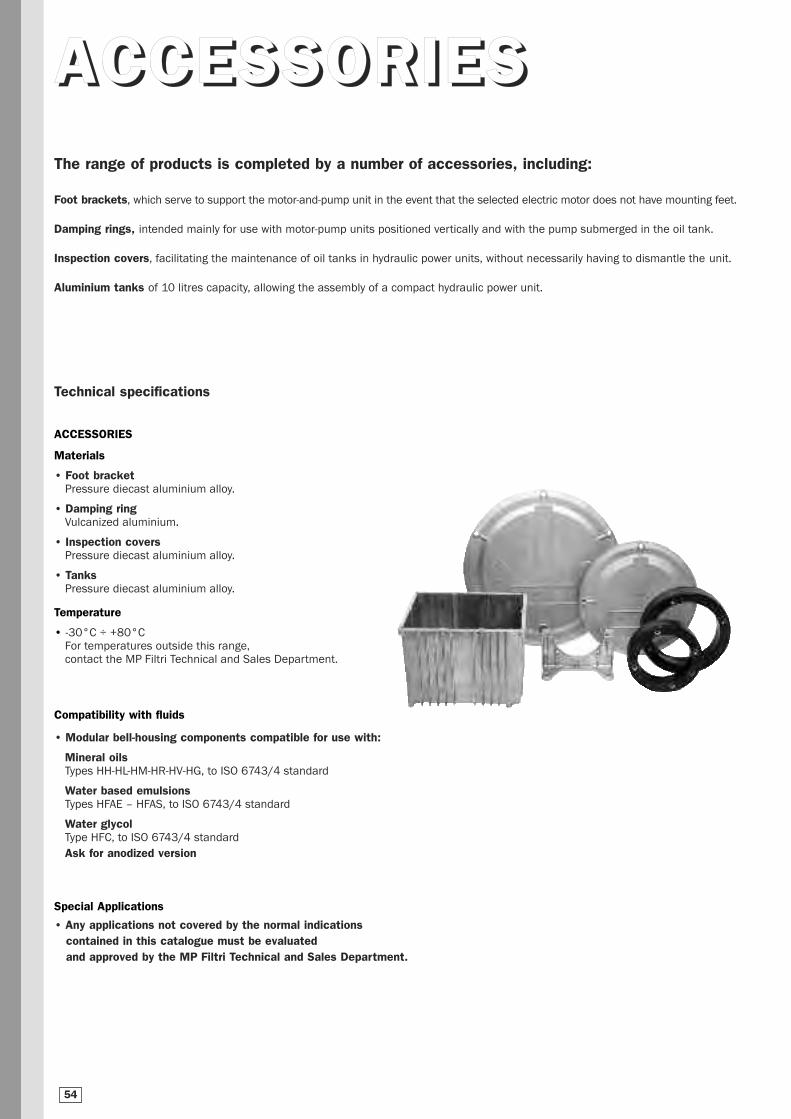
AACCCCEESSSSOORRIIEESSThe range of products is completed by a number of accessories, including:
Foot brackets, which serve to support the motor-and-pump unit in the event that the selected electric motor does not have mounting feet.
Damping rings, intended mainly for use with motor-pump units positioned vertically and with the pump submerged in the oil tank.
Inspection covers, facilitating the maintenance of oil tanks in hydraulic power units, without necessarily having to dismantle the unit.
Aluminium tanks of 10 litres capacity, allowing the assembly of a compact hydraulic power unit.
Technical specifications
ACCESSORIES
Materials
• Foot bracketPressure diecast aluminium alloy.
• Damping ringVulcanized aluminium.
• Inspection coversPressure diecast aluminium alloy.
• TanksPressure diecast aluminium alloy.
Temperature
• -30°C ÷ +80°CFor temperatures outside this range,contact the MP Filtri Technical and Sales Department.
Compatibility with fluids
• Modular bell-housing components compatible for use with:
Mineral oilsTypes HH-HL-HM-HR-HV-HG, to ISO 6743/4 standard
Water based emulsionsTypes HFAE – HFAS, to ISO 6743/4 standard
Water glycolType HFC, to ISO 6743/4 standard
Ask for anodized version
Special Applications
• Any applications not covered by the normal indications contained in this catalogue must be evaluated and approved by the MP Filtri Technical and Sales Department.
54
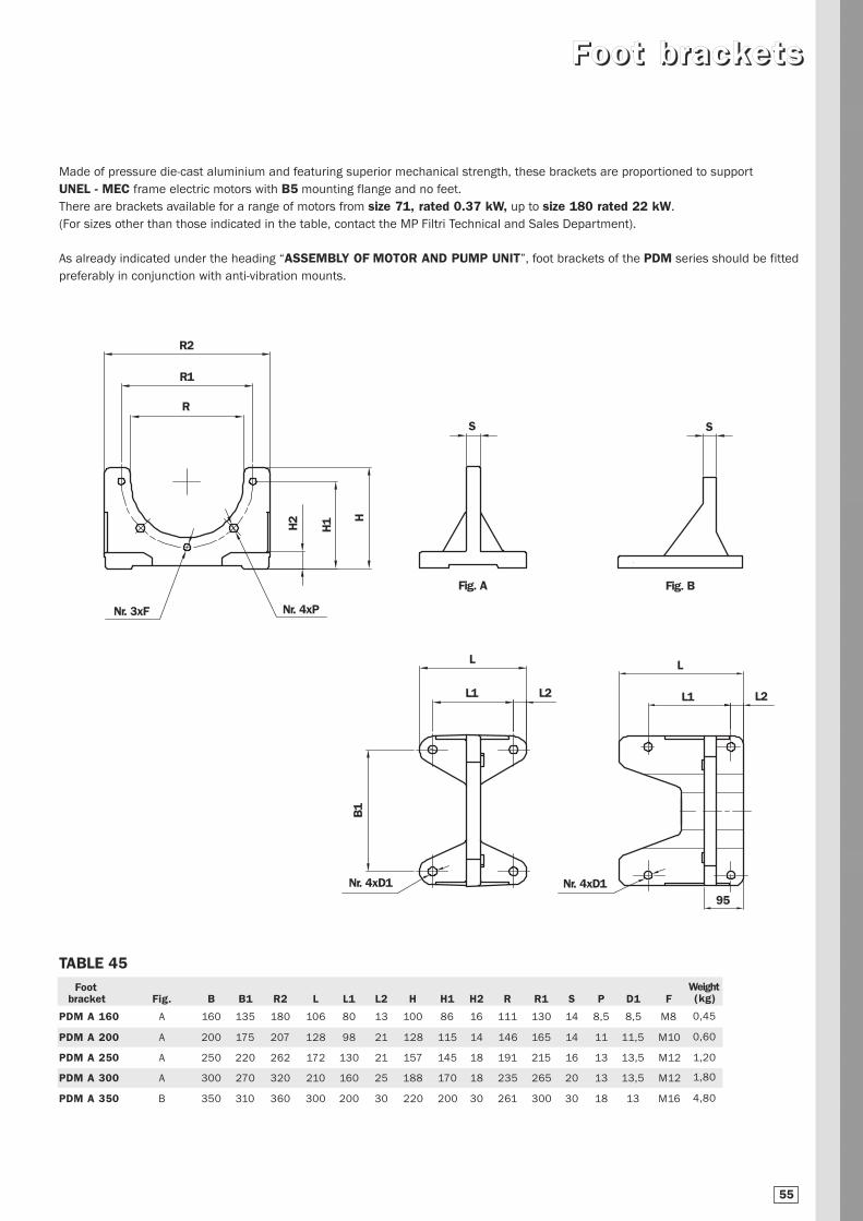
Made of pressure die-cast aluminium and featuring superior mechanical strength, these brackets are proportioned to support
UNEL - MEC frame electric motors with B5 mounting flange and no feet.
There are brackets available for a range of motors from size 71, rated 0.37 kW, up to size 180 rated 22 kW.
(For sizes other than those indicated in the table, contact the MP Filtri Technical and Sales Department).
As already indicated under the heading “ASSEMBLY OF MOTOR AND PUMP UNIT”, foot brackets of the PDM series should be fitted
preferably in conjunction with anti-vibration mounts.
FFoooott bbrraacckkeettss
TABLE 45
L
L2L1
L
95
L1
Nr. 4xD1
R2
R1
R
Nr. 4xD1
Nr. 3xF
S S
Nr. 4xP
H2
H1 H
B1
L2
Footbracket Fig. B B1 R2 L L1 L2 H H1 H2 R R1 S P D1 F
PDM A 160 A 160 135 180 106 80 13 100 86 16 111 130 14 8,5 8,5 M8
PDM A 200 A 200 175 207 128 98 21 128 115 14 146 165 14 11 11,5 M10
PDM A 250 A 250 220 262 172 130 21 157 145 18 191 215 16 13 13,5 M12
PDM A 300 A 300 270 320 210 160 25 188 170 18 235 265 20 13 13,5 M12
PDM A 350 B 350 310 360 300 200 30 220 200 30 261 300 30 18 13 M16
Fig. A Fig. B
Weight(kg)
0,45
0,60
1,20
1,80
4,80
55
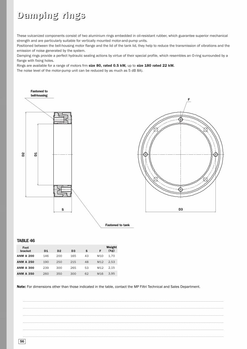
DDaammppiinngg rr iinnggss
TABLE 46
Note: For dimensions other than those indicated in the table, contact the MP Filtri Technical and Sales Department.
These vulcanized components consist of two aluminium rings embedded in oil-resistant rubber, which guarantee superior mechanical
strength and are particularly suitable for vertically mounted motor-and-pump units.
Positioned between the bell-housing motor flange and the lid of the tank lid, they help to reduce the transmission of vibrations and the
emission of noise generated by the system.
Damping rings provide a perfect hydraulic sealing actions by virtue of their special profile, which resembles an O-ring surrounded by a
flange with fixing holes.
Rings are available for a range of motors frm size 80, rated 0.5 kW, up to size 180 rated 22 kW.The noise level of the motor-pump unit can be reduced by as much as 5 dB 8A).
Footbracket D1 D2 D3 S F
ANM A 200 146 200 165 43 M10
ANM A 250 190 250 215 48 M12
ANM A 300 239 300 265 53 M12
ANM A 350 260 350 300 62 M16
Fastened to bell-housing
Fastened to tank
F
D2
D1
S D3
Weight(kg)
1,70
2,53
2,15
3,95
56
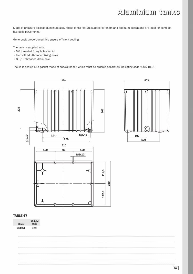
AAlluummiinniiuumm ttaannkkss
Made of pressure diecast aluminium alloy, these tanks feature superior strength and optimum design and are ideal for compact
hydraulic power units.
Generously proportioned fins ensure efficient cooling.
The tank is supplied with:
• M6 threaded fixing holes for lid
• feet with M8 threaded fixing holes
• G 3/8” threaded drain hole
The lid is sealed by a gasket made of special paper, which must be ordered separately indicating code “GUS 10,0”.
310 240
102
170
225
114
G 3
/8”
250
310
100 95 100
112,
511
2,5
240
M6x12
M8x12
207
Code
SE10LT
Weight(kg)
3,95
TABLE 47
57
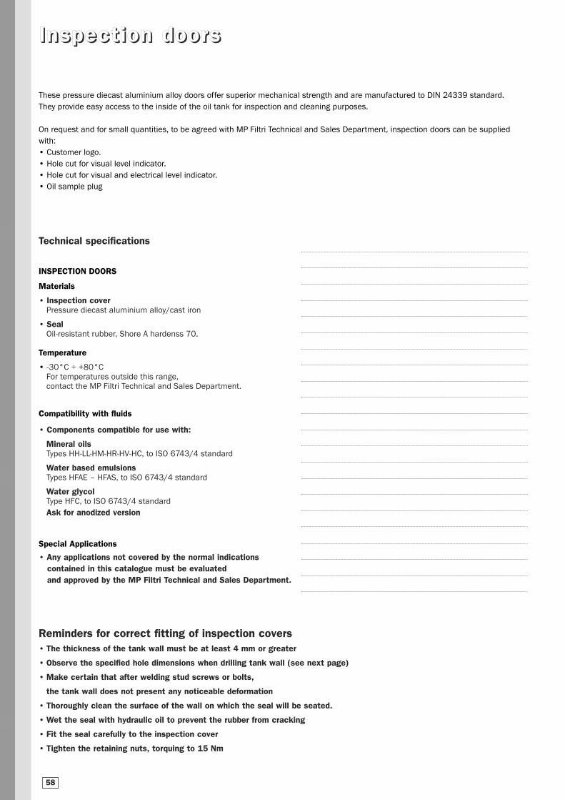
Reminders for correct fitting of inspection covers• The thickness of the tank wall must be at least 4 mm or greater
• Observe the specified hole dimensions when drilling tank wall (see next page)
• Make certain that after welding stud screws or bolts,
the tank wall does not present any noticeable deformation
• Thoroughly clean the surface of the wall on which the seal will be seated.
• Wet the seal with hydraulic oil to prevent the rubber from cracking
• Fit the seal carefully to the inspection cover
• Tighten the retaining nuts, torquing to 15 Nm
IInnssppeecctt iioonn ddoooorrss
These pressure diecast aluminium alloy doors offer superior mechanical strength and are manufactured to DIN 24339 standard.
They provide easy access to the inside of the oil tank for inspection and cleaning purposes.
On request and for small quantities, to be agreed with MP Filtri Technical and Sales Department, inspection doors can be supplied
with:
• Customer logo.
• Hole cut for visual level indicator.
• Hole cut for visual and electrical level indicator.
• Oil sample plug
Technical specifications
INSPECTION DOORS
Materials
• Inspection coverPressure diecast aluminium alloy/cast iron
• SealOil-resistant rubber, Shore A hardenss 70.
Temperature
• -30°C ÷ +80°CFor temperatures outside this range,contact the MP Filtri Technical and Sales Department.
Compatibility with fluids
• Components compatible for use with:
Mineral oilsTypes HH-LL-HM-HR-HV-HC, to ISO 6743/4 standard
Water based emulsionsTypes HFAE – HFAS, to ISO 6743/4 standard
Water glycolType HFC, to ISO 6743/4 standard
Ask for anodized version
Special Applications
• Any applications not covered by the normal indications contained in this catalogue must be evaluated and approved by the MP Filtri Technical and Sales Department.
58
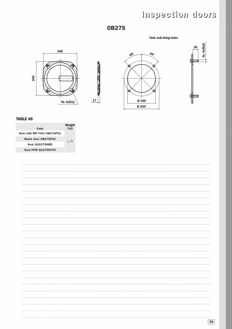
IInnssppeecctt iioonn ddoooorrss
240
Nr. 4xD11
24045°
Ø 250
Ø 195
30
Nr.
4xM
10
OB275
17
45°
Tank wall fixing holes
TABLE 48
Code
Door with MP Filtri OB275P01
Blank door OB275P02
Seal GU0275NBR
Seal FPM GU2750VTN
Weight(kg)
1,76
59
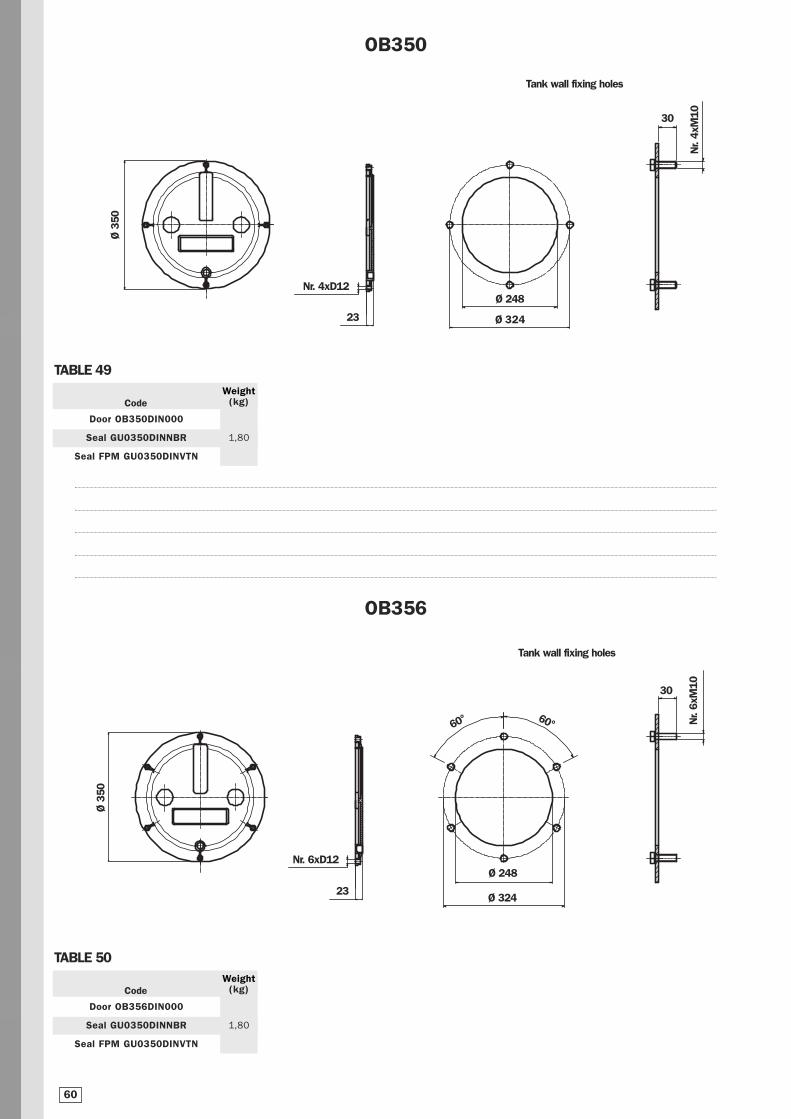
Ø 3
50
Nr. 4xD12
Ø 324
Ø 248
30
Nr.
4xM
10
OB350
Tank wall fixing holes
TABLE 49
Code
Door OB350DIN000
Seal GU0350DINNBR
Seal FPM GU0350DINVTN
Weight(kg)
1,80
23
Ø 3
50
Nr. 6xD12
60°
Ø 324
Ø 248
30N
r. 6x
M10
OB356
60°
Tank wall fixing holes
TABLE 50
Code
Door OB356DIN000
Seal GU0350DINNBR
Seal FPM GU0350DINVTN
Weight(kg)
1,80
23
60
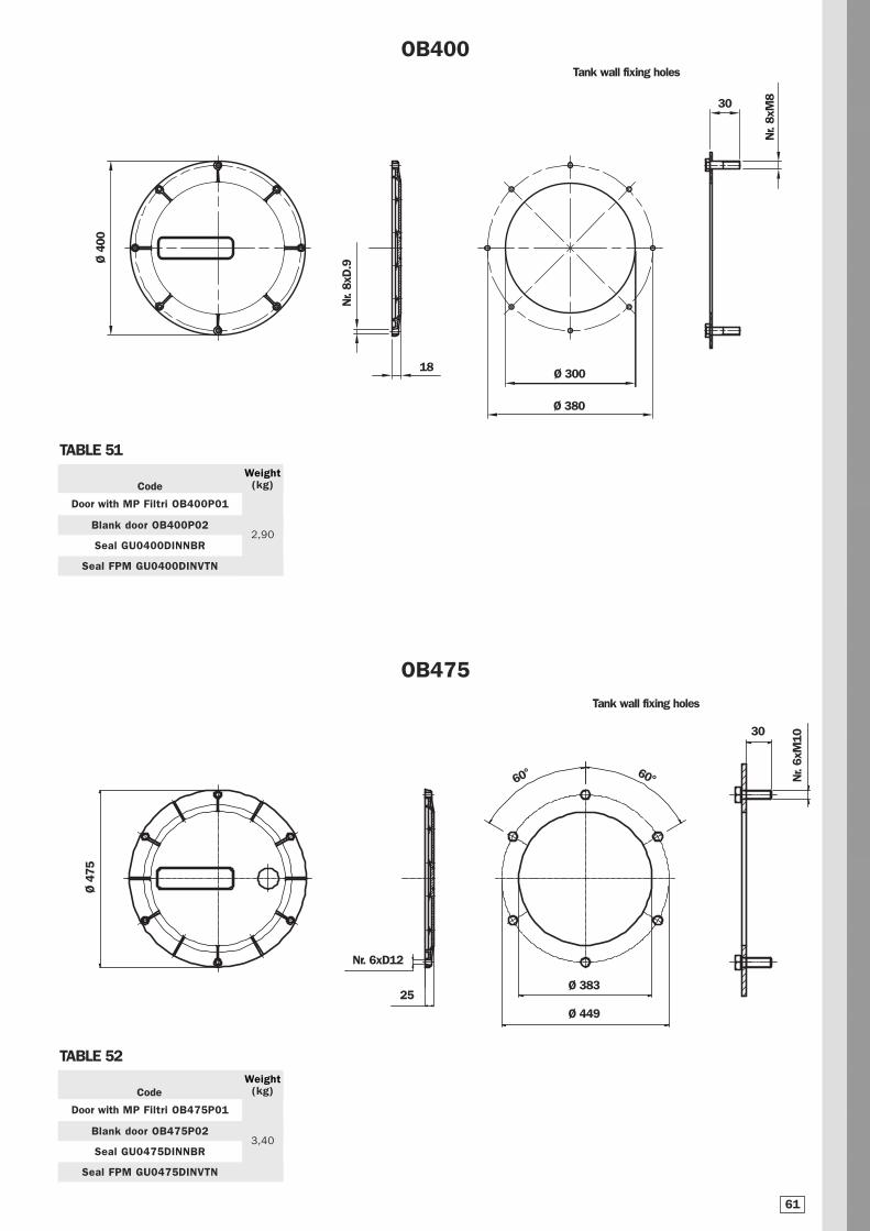
Ø 4
75
Nr. 6xD12
Ø 449
Ø 383
30
Nr.
6xM
10
OB475
60° 60°
Tank wall fixing holes
25
TABLE 52
Code
Door with MP Filtri OB475P01
Blank door OB475P02
Seal GU0475DINNBR
Seal FPM GU0475DINVTN
Weight(kg)
3,40
Ø 380
Ø 4
00
Nr.
8xD
.9
18 Ø 300
30
Nr.
8xM
8
OB400
TABLE 51
Code
Door with MP Filtri OB400P01
Blank door OB400P02
Seal GU0400DINNBR
Seal FPM GU0400DINVTN
Weight(kg)
2,90
61
Tank wall fixing holes
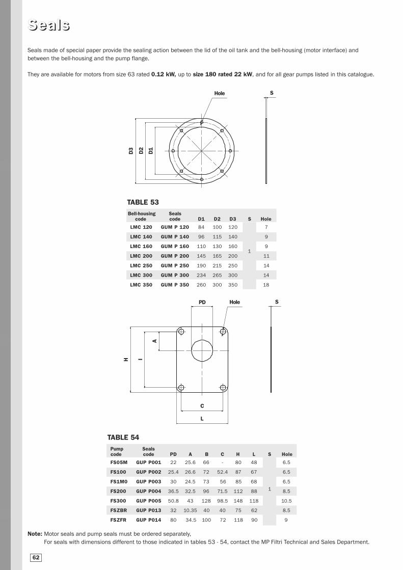
Note: Motor seals and pump seals must be ordered separately,
For seals with dimensions different to those indicated in tables 53 - 54, contact the MP Filtri Technical and Sales Department.
Seals made of special paper provide the sealing action between the lid of the oil tank and the bell-housing (motor interface) and
between the bell-housing and the pump flange.
They are available for motors from size 63 rated 0.12 kW, up to size 180 rated 22 kW, and for all gear pumps listed in this catalogue.
Bell-housing Sealscode code D1 D2 D3 S Hole
LMC 120 GUM P 120 84 100 120 7
LMC 140 GUM P 140 96 115 140 9
LMC 160 GUM P 160 110 130 160 9
LMC 200 GUM P 200 145 165 200 11
LMC 250 GUM P 250 190 215 250 14
LMC 300 GUM P 300 234 265 300 14
LMC 350 GUM P 350 260 300 350 18
Pump Seals code code PD A B C H L S Hole
FS05M GUP P001 22 25.6 66 - 80 48 6.5
FS100 GUP P002 25.4 26.6 72 52.4 87 67 6.5
FS1M0 GUP P003 30 24.5 73 56 85 68 6.5
FS200 GUP P004 36.5 32.5 96 71.5 112 88 8.5
FS300 GUP P005 50.8 43 128 98.5 148 118 10.5
FSZBR GUP P013 32 10.35 40 40 75 62 8.5
FSZFR GUP P014 80 34.5 100 72 118 90 9
1
1
SSeeaallss
Hole
D3
D1
D2
S
TABLE 53
TABLE 54
Hole
H I
A
SPD
C
L
62

IInnssppeecctt iioonn ddoooorr oopptt iioonnss
ØC
6
Visual level indicators LVA series
Materials: Transparent amorphous polyamide lens
Nylon guard
Seals: Series A-NBR - Series V-FPM
A B ØC
LVA 10 76 M 10 11
LVA 20 127 M 12 13
LVA 30 254 M 12 13
Size
Dimensions
Fixing holes in door
See table 55
+10
38 3823
LVA S LVA T 17,5
B
A±
0,5
A±
0,5
A±
0,5
TABLE 55Preparing for to fit the level on request
Code door
OB275**
OB350**OB356**
OB400**OB475**
Code level
LVA 10**
LVA 10**LVA 20**
LVA 10**LVA 20**LVA 30**
64
Operating pressure: Max 1 bar at +80°C
Operating temperature: From -25°C to +80°C
Tightening torque: 10 Nm max.
Mineral oils - Synthetic oils - Water base emulsions - Phosphoric esters

LLVVAA oorrddeerr iinngg ii nnffoorrmmaatt iioonn
LVA1 2 3 4Visual level indicators
Example: LVA 10 S A M10 P01
5 - Customizations
P01 Nameplate with MP
P02 Blank nameplate MP (Min. 1000 pcs)
Pxx Customized (4 Min. 1000 pcs)
5
P
Details contained in this publication are guideline only. MP Filtri reserves the right to make changes at any given time to the models described, whether for
technical or marketing reasons. The colours of products are purely indicative. Reproduction forbidden. All rights reserved.
4 - Options
M10 M10 screws (standard for LVA 10)
M12 M12 screws (standard for LVA 20/30)
65
Note: For customization features other than those indicated on this page, contact the MP Filtri Technical and Sales Department.
1 - Sizes
10
20
30
2 - Accessories
S Without
T With thermometer
3 - Seals
A NBR
V FPM
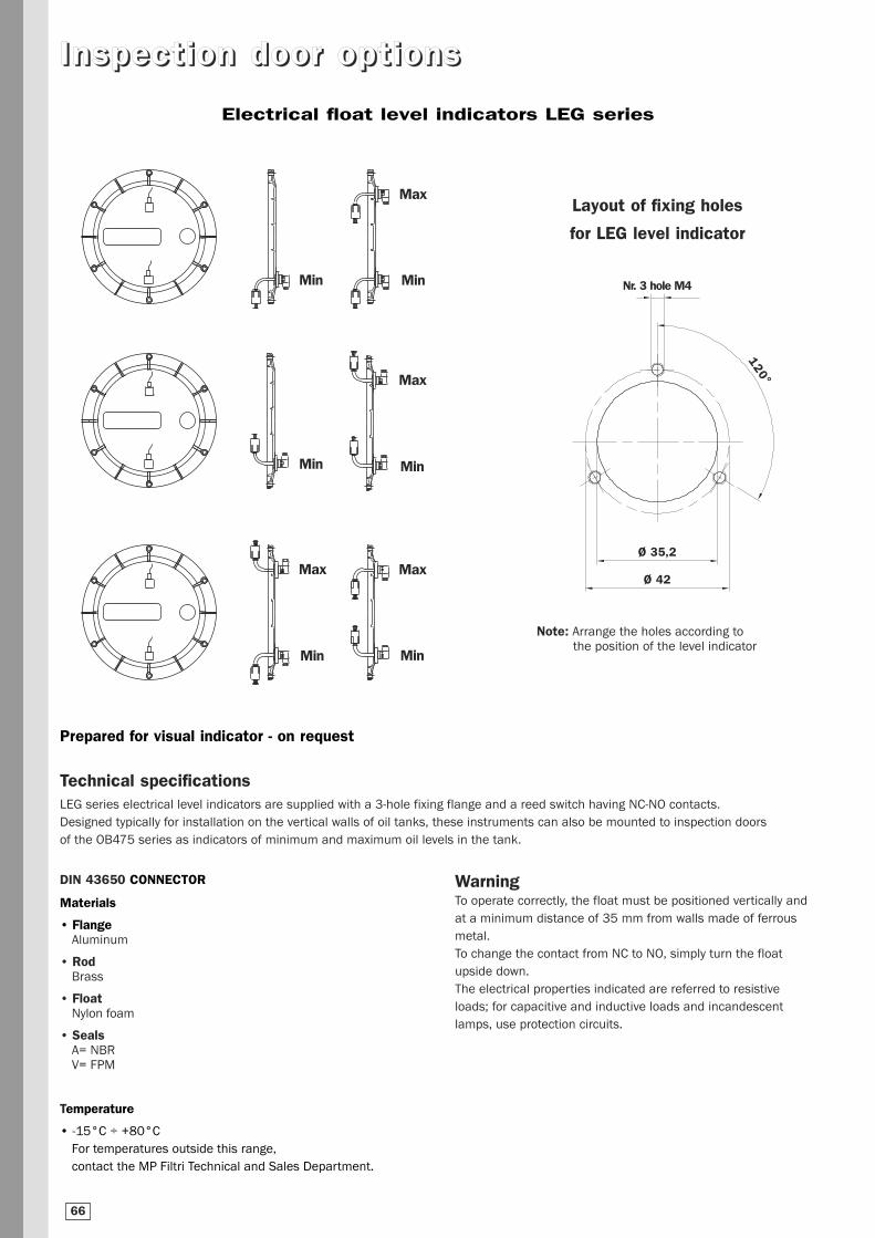
IInnssppeecctt iioonn ddoooorr oopptt iioonnss
Min
Min
Min
Min
Max
Max
Min
Max
Min
Max
Layout of fixing holes
for LEG level indicator
Note: Arrange the holes according to the position of the level indicator
Electrical float level indicators LEG series
Nr. 3 hole M4
Ø 35,2
Ø 42
120°
Technical specificationsLEG series electrical level indicators are supplied with a 3-hole fixing flange and a reed switch having NC-NO contacts.
Designed typically for installation on the vertical walls of oil tanks, these instruments can also be mounted to inspection doors
of the OB475 series as indicators of minimum and maximum oil levels in the tank.
WarningTo operate correctly, the float must be positioned vertically and
at a minimum distance of 35 mm from walls made of ferrous
metal.
To change the contact from NC to NO, simply turn the float
upside down.
The electrical properties indicated are referred to resistive
loads; for capacitive and inductive loads and incandescent
lamps, use protection circuits.
DIN 43650 CONNECTOR
Materials
• FlangeAluminum
• RodBrass
• FloatNylon foam
• SealsA= NBRV= FPM
Temperature
• -15°C ÷ +80°C
For temperatures outside this range,
contact the MP Filtri Technical and Sales Department.
66
Prepared for visual indicator - on request

IInnssppeecctt iioonn ddoooorr oopptt iioonnss
LLEEGG oorrddeerr iinngg ii nnffoorrmmaatt iioonn
Details contained in this publication are guideline only. MP Filtri reserves the right to make changes at any given time to the models described, whether for
technical or marketing reasons. The colours of products are purely indicative. Reproduction forbidden. All rights reserved.
70
Ø 30
27
45
69
HON
Length
103200300350
H
103
200
300
350
LEG 1 Float
To invert the contact status
from NO to NC and vice versa,
simply invert the float.
1 2
67
LEG1 2 3 4
Electrical floatlevel indicatorsseries
Example: LEG A 102 2 A 1 A F S P01
1 - Tube material
A Brass
2 - Length
102
3 - Number of floats
1 Nr. 1 float
4 - Float material
A Nylon foam
5
Note: For customization features other than those indicated on this page, contact the MP Filtri Technical and Sales Department.
6 7 8 9
5 - Changeover contacts
1 NC
6 - Seals
A NBR
V FPM
7 - Type of fixing
F 3 hole flange
8 - Electrical connection
S DIN 43650 connector
9 - Options
P01 MP Filtri standard
Pxx On request
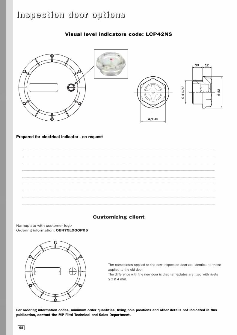
IInnssppeecctt iioonn ddoooorr oopptt iioonnss
Nameplate with customer logo
Ordering information: OB475LOGOP05
For ordering information codes, minimum order quantities, fixing hole positions and other details not indicated in this publication, contact the MP Filtri Technical and Sales Department.
Visual level indicators code: LCP42NS
Customizing client
The nameplates applied to the new inspection door are identical to those
applied to the old door.
The difference with the new door is that nameplates are fixed with rivets
2 x ø 4 mm.
68
Prepared for electrical indicator - on request
13
A/F 42
12
G 1
1/4
”
Ø 5
2

SSuummmmaarr yy ttaabbllee,, eelleecctt rr iicc mmoottoorrss
Power
8-pole 50 Hz 6-pole 50 Hz 4-pole 50 Hz 2-pole 50 Hz Flange dimensions750 rpm 1000 rpm 1500 rpm 3000 rpm Frame dimensions code B5/V1 B1/V18
kW HP kW HP kW HP kW HP size
0.06 0,08 0,12 0,16 0,18 0,2463 11x23 M01
140
0.09 0.12 0.18 0.24 0.25 0.34 90
0,09 0,12 0.18 0,24 0,25 0,34 0,37 0,5071 14x30 M02
160
0,12 0,16 0.25 0.34 0.37 0.50 0.55 0.75 105
0,18 0,24 0.37 0,50 0,53 0,75 0,75 1,0280 19x40 M03
200
0,25 0,34 0.55 0.75 0.75 1.02 1.10 1.50 120
0,37 0,50 0.75 1,02 1,10 1,50 1,50 2,0490 24x50 M04
200
0,55 0,75 1.10 1.50 1.50 2.04 2.20 3.00 140
0,75 1,02 1,50 2,04 2,20 3,00 3,00 4,05 10028x60 M05
250
1,50 2,04 2,20 3,00 4,00 5,44 4,00 5,44 112 160
2,20 3,00 3,00 4,08 5,50 7,50 5,50 7,50132 38x80 M06 300
3,00 4,08 5,50 7,50 7,50 10,20 7,50 10,20
4,00 5,44 7,50 10,20 11,00 15,00 11,00 15,00160 42x110 M07 350
7,50 10,20 11,00 15,00 15,00 20,40 18,00 25,16
11,00 15,00 15 20,4018,50 25,16
22,00 30,00 180 48x110 M08 35022,00 30,00
15,00 20,4018,5 25,16
30,00 40,8030,00 40,80
200 55x110 M09 40022,00 30,00 37,00 50,32
45,00 61,20 225 55x110 M09 450
18,50 24,1830,00 40,80
37,00 50,32225 60x140 M10 450
22,00 30,00 45,00 61,20
55,00 74,80 250 60x140 M10 550
30,00 40,80 37,00 50,32 55,00 74,80 250 65x140 M11 550
75,00 102,00280 65x140 M11 550
90,00 122,40
37,00 50,32 45,00 61,20 75,00 102,00280 75x140 M12 550
45,00 61,20 55,00 74,80 90,00 122,40
110,00 148,60315 65x140 M11 660
200,00 272,00
55,00 74,80 75,00 102,00 110,00 149,60315 80x170 M13 660
110,00 149,60 132,00 179,50 200,00 272,00
250,00 340,00355 75x140 M12 800
315,00 428,40
132,00 178,52 160,00 217,80 250,00 340,00355 95x170 M15 800
20,00 272,00 250,00 340,00 315,00 428,40
355,00 482,80400 80x170 M13 800
400,00 544,00
250,00 340 315,00 428,40355,00 482,80
400 100x210 M16 800400,00 544,00
TABLE 56
69