
Bell & Gossett REVISION B SERIES WC & WCSs3.supplyhouse.com/product_files/180001-Replacement...
12
SERIES WC & WCS Replacement Parts for Hoffman Watchman ® Series WC ® & WCS ® Condensate Units Watchman ® Series WC Cast Iron Receiver Single or Duplex Watchman ® Series WCS Steel Receiver Single or Duplex Bell & Gossett ® Parts List DN0436 REVISION B
Transcript of Bell & Gossett REVISION B SERIES WC & WCSs3.supplyhouse.com/product_files/180001-Replacement...

SE
RIE
S W
C &
WC
SReplacement Parts for
Hoffman Watchman® SeriesWC® & WCS® CondensateUnits
Watchman® Series WCCast Iron ReceiverSingle or Duplex
Watchman® Series WCSSteel Receiver
Single or Duplex
Bell & Gossett®
Parts List DN0436REVISION B
PARTS LIST DN0436 SERIES WC & WCS
2
Index How To Use This Parts List . . . . . . . . . . . . . . . . . . . . . . . . . . . . . . 3Identifying Your Watchman Unit . . . . . . . . . . . . . . . . . . . . . . . . . .4-7Pump Parts for “B” Style Pump . . . . . . . . . . . . . . . . . . . . . . . . . . . .8Pump Parts for “A” Style Pump . . . . . . . . . . . . . . . . . . . . . . . . . . . .8Float Switches & Mechanical Alternators . . . . . . . . . . . . . . . . . . . . .9Receivers, Conduit Assemblies & Misc. Parts . . . . . . . . . . . . . . . .10

PARTS LIST DN0436 SERIES WC & WCS
3
How to use this PARTS LISTThe unit nameplate identifies the Watchman unit by its respective unit designation as is shownbelow.
The nameplate identifies the pump in the example above as a Series WC, model numberWC 6-20-B. The serial number that is noted on the nameplate corresponds to the Bell & Gossettcommodity code number that has appeared on your Domestic/Hoffman price sheets.
Units that have nameplates showing the former Shippensburg, PA address will not referto commodity codes and should be identified by the physical characteristics of the pumpsfurnished on the unit.
• All Shippensburg, PA built units were furnished with the “A” Design Receivers. (SeePages 6 and 7.)
• Units manufactured between December 1, 1982 and September 30, 1983 will show theShippensburg, PA address and were furnished with the “B” Style Pumps and “A” DesignReceivers.
• Units manufactured between October 1, 1983 and June 30, 1990 show the Morton Grove, ILaddress and were furnished with the “B” Style Pumps and “A” Design Receivers.
• Units manufactured after July 1, 1990 were furnished with both the “B” Style Pumps and “B”Design Receivers.
The following procedure is recommended for determining appropriate replacement parts.
1. Determine if the address shown on the nameplate is Shippensburg, PA (all units manufac-tured 1983 or earlier) or Morton Grove, IL (all units after October 1, 1983).
2. Determine by physical characteristics if the Pump is a Packed Construction, “A” Style or “B”Style. Refer to pages 4, 5 & 6 for information regarding how to determine if pump is Packed,“A” or “B” Style.
3. Select items from drawings on pages 6 and 7.
4. Refer to the index to determine appropriate pages for parts information.
ITT Fluid Technology CorporationMorton Grove, Illinois 60053
TMSERIES MODEL
GPM
VOLT 115 PH 1 HZ 60
PSI
DN
0039
HOFFMAN™ WATCHMAN®
CONDENSATE UNITWC
9 20
SERIES 16001 E48
WC-6-20-B

PARTS LIST DN0436 SERIES WC & WCS
4
Identifying Your Watchman UnitDue to the fact that the Watchman unit is a factory stocked product, unique serial numbers havenot been applied to the product. It is therefore necessary to identify the specific generation ofproduct by the physical characteristics of the pump and of the receiver.
Figure 1 on the following page indicates two types of piping arrangements that have been usedfor the Watchman. You’ll note the Packing Construction and “A” Style Watchman indicates adischarge pipe that is parallel to the receiver face (a 90 degree discharge from the pump suc-tion). The “B” Style is piped perpendicular to the receiver face (a 180 degree or in-line dischargefrom the pump suction). This only applies to the “A” design receiver configuration.
Figure 2 shows cut-away drawings of all three generations of pumps used on the Watchman.The uniquely identifiable characteristics of each generation is the discharge orientation and thenumber of capscrews used to hold the volute to the motor (or motor bracket). By using thesetwo easily identifiable characteristics, and referring to the following chart, it is possible to iden-tify the style of pump on the unit.
Suction to No. ofDischarge Orientation Capscrews
Packed Pump 90 4“A” Style 90 3“B” Style 180 4
Figure 3 indicates the parts required to adapt the current “B” Style pump and motor assemblyto replace the older design “A” Style pump. Note that the adapter piping is about 1/2" wider thanthe “A” Style pump and motor discharge position. This can be taken up by use of a short nippleand/or a union in place of the existing discharge piping.

PARTS LIST DN0436 SERIES WC & WCS
5
VENT
VENT
VENT
VENT
HOFFMANSTRAINER HOFFMAN
STRAINER
BY-PASSTO DRAIN
BY-PASSTO DRAIN
GATE-VALVE
GATE-VALVE
PLUG COCK
PLUG COCK
CHECK VALVE
CHECK VALVE
MAIN RETURNFROM HEATINGSYSTEM MAIN RETURN
FROM HEATINGSYSTEM
OVERFLOWTO DRAIN
OVERFLOWTO DRAIN
OVERFLOWLOOP FILL OVERFLOW
LOOP FILL
FIGURE 1
FIGURE 2
WC PACKED AND “A” STYLE WC “B” STYLE
FIGURE 3
15
14
12
10
16 13
11
17
15
24
886
3
9
7
12 10
7
1
2
9
8
6
11
5
3
4
PACKED PUMP “A” STYLE “B” STYLE
25/64
1/2"
45/32
VOLUTE
25/64
DISCHARGE
Piping Conversion“B” To “A” StyleLocation
Items Required ToAdjust Piping
(1) 3/4" 90° Street Elbow(1) 3/4" X 2" Nipple(1) 3/4" 90° Elbow(1) 3/4" X 21/2" Nipple(1) 3/4" 90° Elbow

PARTS LIST DN0436 SERIES WC & WCS
6
61/2 MIN.
61/2 MIN.
3/4 NPT DISCHARGE
11/4 NPT DRAIN
GREENFIELD CONDUIT
11/441/4
41/4
13/8
21/8
21/8
13/8 31/8
115/8 11/4 NPT DRAIN
GREENFIELDCONDUIT
3/4" NPT DISCHARGE
PRIMARY INLET
PRIMARY INLET
FLOAT SWITCH
FLOAT SWITCH(SIMPLEX)
THIS PUMP DUPLEX UNIT ONLY
ALTERNATEBASKETSTRAINERLOCATION
ALTERNATEBASKETSTRAINERLOCATION
OPTIONAL BASKET STRAINERSHIPPED LOOSE (ALTERNATEMOUNTING SHOWN)
OPTIONAL BASKET STRAINERSHIPPED LOOSE (ALTERNATEMOUNTING SHOWN)
WATCHMAN PUMP
WATCHMAN PUMP
MECHANICAL ALTERNATOR(DUPLEX)
6 & 9 GALLON “B” STYLE PUMP / “B” DESIGN RECEIVER
14 GALLON “B” STYLE PUMP / “B” DESIGN RECEIVER
611/16"85/8"
11/2 NPT VENT
11/2
241/4
131/8
611/16
13/4 13/4
71/4 20
1/4 21/8
23/8 13/8 1/4 13/8
13/813/4
3/4 NPTDISCHARGE
B
G
A
D E
3/4" NPTDISCHARGE
PUMP
2 NPT INLET
5FLOAT
SWITCH
DRAIN
DRAIN
FLOAT SWITCH ORMECHANICALALTERNATOR
PUMP NO. 1
MPUMP NO. 2
C
F
H
H
SINGLE
(DUPLEX ONLY)
DUPLEX
2 NPT INLET
11/4 NPT VENT
11/4 NPT OVERFLOW
2 NPT OVERFLOW
6 GALLON “B” STYLE PUMP / “A” DESIGN RECEIVER
EDR STYLE REC. CAP A B C D E F G H M8,000 Single 9 241/2 133/8 85/8 95/8 9 71/2 43/4 203/4 15
12,000 Single 14 263/8 133/8 91/2 101/2 97/8 53/4 43/4 2313/16 1712,000 Duplex 14 263/8 133/8 91/2 101/2 97/8 53/4 43/4 317/8 17
9 & 14 GALLON “B” STYLE PUMP / “A” DESIGN RECEIVER
PARTS LIST DN0436 SERIES WC & WCS
7
DRAIN DISCHARGE 3/4"
221/4"
141/2" MAX.
611/16"
203/16"
2" INLET
2" OVERFLOWVENT
1" VENT
FLOAT SWITCH
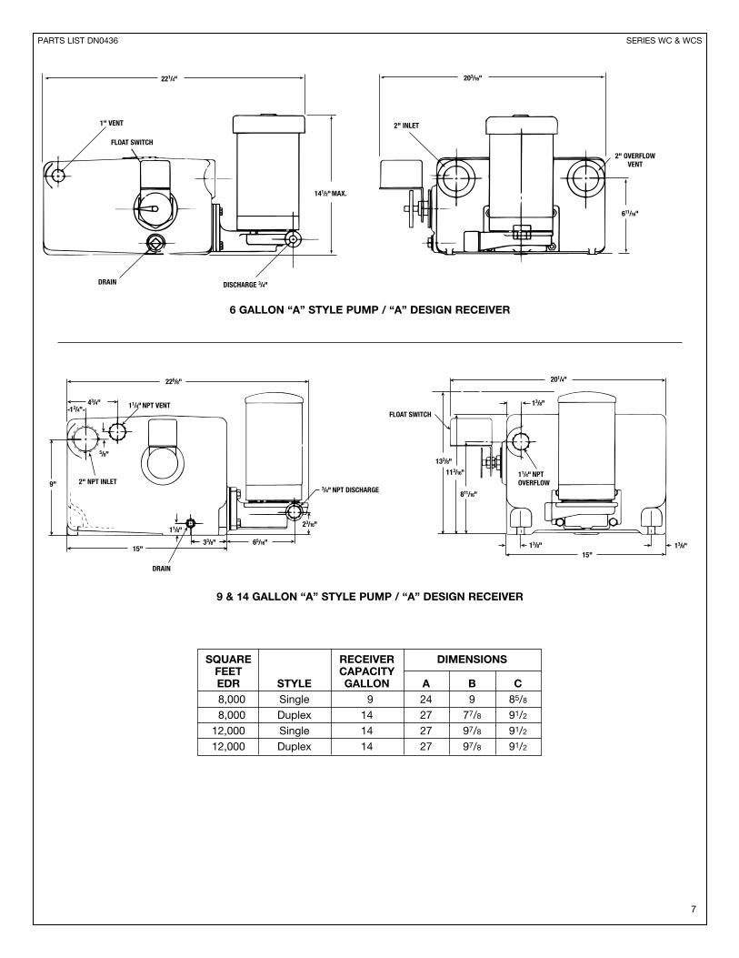
6 GALLON “A” STYLE PUMP / “A” DESIGN RECEIVER
225/8"
43/4"
33/8"
5/8"
65/16"
113/16"
133/8"
201/4"
13/8"
811/16"
23/16"
11/4" NPTOVERFLOW
13/8" 13/8"15"
11/4" NPT VENT
3/4" NPT DISCHARGE
FLOAT SWITCH13/4"
11/8"
9"
15"
2" NPT INLET
DRAIN
SQUARE RECEIVER DIMENSIONSFEET CAPACITYEDR STYLE GALLON A B C8,000 Single 9 24 9 85/8
8,000 Duplex 14 27 77/8 91/2
12,000 Single 14 27 97/8 91/2
12,000 Duplex 14 27 97/8 91/2
9 & 14 GALLON “A” STYLE PUMP / “A” DESIGN RECEIVER

PUMPSMANUFACTURED PUMPSBETWEEN 1983 MANUFACTURED
TO 2003 AFTER 2003ITEM NUMBER PART PART
NUMBER DESCRIPTION REQUIRED NUMBER NUMBER1 Motor 1/3 hp, 1 ph, 3500 rpm 1 DM0005 DM00052 Seal Holder 1 DP0290 DP19663 Seal 1 – –4 Impeller 1 DP0321 DP03215 Head Gasket 1 DG0092 DG00926 Pump Case with Wearing Ring 1 DP1665 DP16657 Capscrew 4 DJ0083 DJ00838 Wear Ring 1 DP0482 DP04829 Pipe Plug 1/4" 1 P39040 P39040
10 Wire Spacer 1 DP0291 –11 Water Slinger 1 DP0848 DP0848
Seal Kit including MechanicalSeal, Head Gasket & Case to 1 180013 180013Receiver GasketComplete Pump andMotor Assembly 1 180001 180001
PARTS LIST DN0436 SERIES WC & WCS
8
10
7
1
2
9
8
6
11
5
3
4
6
8
9
11
7
1
115
2
3
4
Order Replacement Parts by Description and Part No.Specify Serial No. shown on nameplate.
AFTER 2003 1983-2003

PARTS LIST DN0436 SERIES WC & WCS
9
ITEM NUMBER PARTNUMBER DESCRIPTION REQUIRED NUMBER
1-5 Motor with Pump Head 1 1800614 Water Slinger 1 DP08485 Pump Head 1 DP02067 Head Gasket 1 DG01348 Impeller 1 DP03219 Case Wearing Ring 1 DP0482
9-10 Pump Case with Wearing Ring 1 DP160216 Head to Case Capscrews 3 DJ007717 Case to Receiver Gasket 1 DG0060
Seal Kit including Mechanical* Seal, Head Gasket & Case to 1 180013
Receiver GasketComplete Pump andMotor Assembly 1 180060
WATCHMAN “A” STYLE PUMP AND MOTOR ASSEMBLY
15
14
12
10
16 13
11
17
15
24
886
3
9
7
12
Order Replacement Parts by Description and Part No.Specify Serial No. shown on nameplate.* Seal only. Consult factory.
– Factory recommended spare parts.

PARTS LIST DN0436 CONTINUED SERIES WC & WCS
10
FLOAT SWITCH ASSEMBLY
INSTRUCTIONS
APPLICATION – For automatically controlling the liquid level ina closed tank by float movement.
MOUNTING – Screw-in Tank Float Switches are mounteddirectly to the tank by means of the 21/2" I.P.S. threaded fitting(D). Before screwing this fitting into the tank, loosen Nut (C) sothat the fitting (D) is free to rotate in the switch bracket. Tightenthe fitting (D) so that there will be no leak past the threads. Thenrevolve the switch case until it is horizontal and tighten Nut (C).
REVERSE ACTION – To change, relocate operating link to theopposite slot in base plate and corresponding hole in adjustingplate.
ADJUSTMENT – Switches are shipped from the factory set fora specified float travel. Reasonable adjustment of float travelcan be made in the field by moving adjusting strips (7) whichare held in place by Screws (A) and (B). Loosening Screw (B)and moving upper adjusting strip (7) will affect the upper limitof float travel only. Loosening Screw (A) and moving loweradjusting strip (7) will affect the lower limit of float travel.
CAUTION: Switches are shipped with a bracket attached tothe mounting plate. This bracket prevents the float and the rodfrom moving in the tank during shipment. When installing thesystem, this clearly marked shipping bracket must be removedand discarded.
7
7
B
A
2
5
1
C D
43
MECHANICAL ALTERNATOR ASSEMBLY
INSTRUCTIONS
APPLICATION – Mechanical alternators serve to open andclose an electric circuit by an upward and downward floatmovement. The forces are applied by means of a float operat-ing between different liquid levels. The action is such that twoswitch units are alternated on successive cycles. If the liquidlevel continues to rise or fall with one pump in operation, thelever will continue to travel to a further position at which pointthe “second” switch will be operated, throwing the stand-bypump across the line.
MOUNTING – Mechanical alternators are mounted directly tothe tank by means of the 21/2" I.P.S. threaded fitting (D). Beforescrewing this fitting into the tank, loosen Nut (C) so that the fit-ting (D) is free to rotate in the switch bracket. Tighten the fitting(D) so that there will be no leak past the threads. Then revolvethe switch case until it is horizontal and tighten Nut (C).
STANDARD OPERATION – Contacts are arranged for sumpaction. In this form the contacts will close on increase in liquidlevel.
REVERSE ACTION – To change, relocate operating link to theopposite slot in base plate and corresponding hole in adjustingplate.
ADJUSTMENT – Switches are shipped from the factory set fora specified float travel. Reasonable adjustment of float travelcan be made in the field by moving adjusting strips (7) which
are held in place by Screws (A) and (B). Loosening Screw (B)and moving upper adjusting strip (7) will affect the upper limitof float travel only. Loosening Screw (A) and moving loweradjusting strip (7) will affect the lower limit of float travel.
CAUTION: Switches are shipped with a bracket attached tothe mounting plate. This bracket prevents the float and the rodfrom moving in the tank during shipment. When installing thesystem, this clearly marked shipping bracket must be removedand discarded.
7
7 B
A
2
5
1
C
D4
3
ITEM NUMBER PARTNUMBER DESCRIPTION REQUIRED NUMBER
Complete Float Switch1 with Foat – NEMA 11 DA0393
4 Float 1 DA0165* Float Switch Seal Kit 1 180095
ITEM NUMBER PARTNUMBER DESCRIPTION REQUIRED NUMBER
Complete Mech. Altr.1 with Foat – NEMA 11 DA0361
4 Float 1 DA0165* Float Switch Seal Kit 1 180095

PARTS LIST DN0436 CONTINUED SERIES WC & WCS
11
MOTOR2
MOTOR1
MOTOR1
MOTOR2
MOTOR
MOTOR1
115/
1 60
*LI
NE
115/
1/60
*LI
NE
115/
1/60
*LI
NE
L1
L2
L1
L2
L1
L2
FLOAT SWITCHPOWER SUPPLY,PRIMARY PROTECTIONBY OTHERS
1DW129A 1DW130A
1DW129B 1DW130B
LIN
ELI
NE
LIN
E
L2
L1
L2
L1
L2
L1
POWER SUPPLY,PRIMARY PROTECTIONBY OTHERS
POWER SUPPLY,PRIMARY PROTECTIONBY OTHERS
POWER SUPPLY,PRIMARY PROTECTIONBY OTHERS
FLOAT SWITCH
MECHANICALALTERNATOR
MECHANICALALTERNATOR
REPRESENTATIVE WIRING DIAGRAMS
WATCHMAN® SIMPLEX UNITS, SINGLE PHASE
WATCHMAN® AND SCC1 DUPLEX UNITS, SINGLE PHASE
FIELD WIRING SHOULD BE IN ACCORDANCE WITHNATIONAL ELECTRIC CODE.
DASHED LINE WIRING & COMPONENTS BY OTHERS
*230/1/60 VOLTAGE PERMISSIBLE IF MOTOR ISRECONNECTED PER 'HIGH VOLTAGE' DIAGRAMON MOTOR AND APPLICABLE PRIMARY PROTECTIONIS SUPPLIED.
SIZE PART NUMBER6 Gallon B DR06109 Gallon B DR0612
14 Gallon B DR0614
6 Gallon B Steel DT04609 Gallon B Steel DT0461
14 Gallon B Steel DT0462
6 Gallon A DR02029 Gallon A DR0206
14 Gallon A Simplex DR021614 Gallon A Duplex DR0214
– Factory recommended spare parts.
RECEIVERS6 Gallon B DE00849 Gallon B DE0084
14 Gallon B DE0084
6 Gallon A DE08029 Gallon A DE0802
14 Gallon A Simplex DE0802DE0802 &14 Gallon A Duplex DE0804
CONDUIT ASSEMBLIES
MISCELLANEOUS PARTSBlind Flange DF0210Gasket DG0060Mounting Capscrews (4) DJ0113

ITT8200 N. Austin AvenueMorton Grove, IL 60053Phone: (847) 966-3700Fax: (847) 966-9052www.bellgossett.com
INTL.ITT / Export Dept.8200 N. Austin AvenueMorton Grove, IL 60053Phone: (847) 966-3700Fax: (847) 966-2384www.bellgossett.com
CANADAITT R&CW Canada55 Royal RoadGuelph, Ontario,N1H 1T1, CanadaPhone: (519) 821-1900
© COPYRIGHT 2007 BY ITT CORPORATIONPRINTED IN U.S.A. 12-07
THE ITT ENGINEERED BLOCKS SYMBOL ANDENGINEERED FOR LIFE ARE REGISTEREDTRADEMARKS OF ITT CORPORATION