BEIS Presentation Future CCS technologies Paul Fennell
41
1 BEIS Presentation Future CCS technologies Paul Fennell [email protected] Department of Chemical Engineering
Transcript of BEIS Presentation Future CCS technologies Paul Fennell

1
BEIS Presentation
Future CCS technologies
Paul [email protected]
Department of Chemical Engineering

Topics Covered
2
What’s wrong with CCS now?
How can CCS be improved in the future?
Questions to ask
Why CCU isn’t the future

Minimum work for separation
Redrawn based on Wilcox, J., “Carbon Capture”
• The more dilute the exhaust gas, the more work required to separate the CO2
• The piper has to be paid• You might give up ¼ of the
electricity output from a power station to capture the CO2 from it at the exhaust.
• If you emit the CO2 and then capture it from the air, ceteris paribus you would use ¾ of the electricity.
338 K
CO2 in air (380 – 580 ppm)
298 K
CO2 in NGCC (5 – 8 %)
CO2 in PCC (5 – 8 %)
CO2 in IGCC (40 – 60 %)
0 0.2 0.4 0.6 0.8 1.0
Wor
k (k
J / m
olCO
2 )
0
5
10
15
20
Mol fraction of CO2

Post-combustion capture with chemical absorption
Heat input for regeneration of solvent accounts for decrease in process /cost efficiency
Figure courtesy of the Grantham Institute Briefing paper number 3.
THIS BIT COSTS MONEY TOO. CAPITAL COSTS MONEY. DON’T JUST FOCUS ON OPEX, CAPEX TOO!
Improvements can be made to both.

• Solvents will continue to improve.• IF there’s a sufficient CO2 price, solvent scrubbing will be deployed
Reproduced from DOI: 10.1039/C3EE42350F (Review Article) Energy Environ. Sci., 2014, 7, 130-189 with permission from The Royal Society of Chemistry
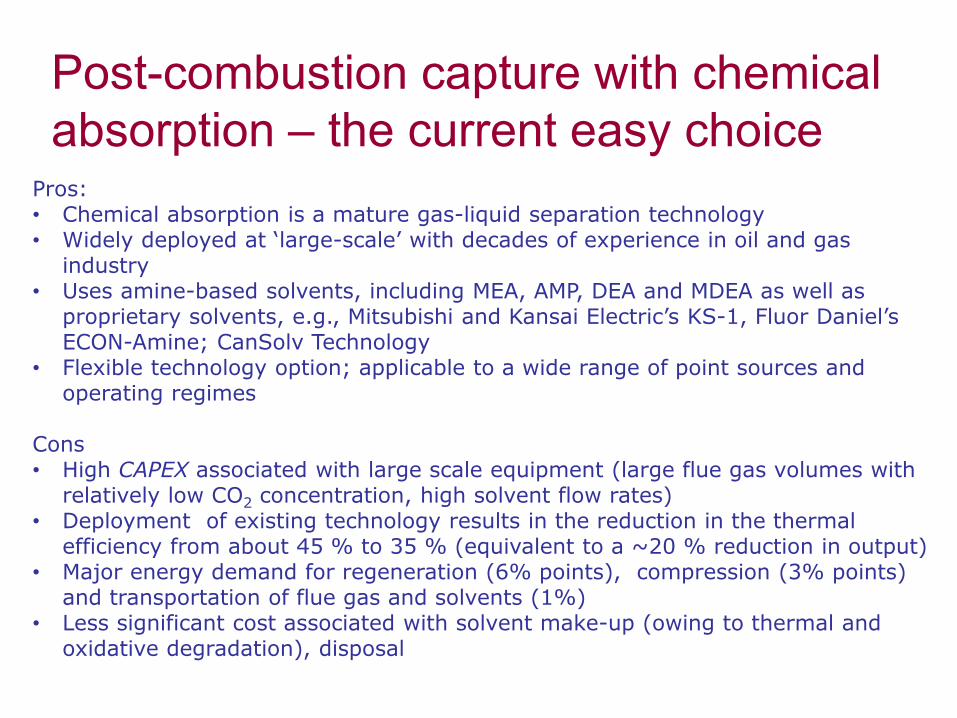
Post-combustion capture with chemical absorption – the current easy choice
Pros:• Chemical absorption is a mature gas-liquid separation technology• Widely deployed at ‘large-scale’ with decades of experience in oil and gas
industry• Uses amine-based solvents, including MEA, AMP, DEA and MDEA as well as
proprietary solvents, e.g., Mitsubishi and Kansai Electric’s KS-1, Fluor Daniel’s ECON-Amine; CanSolv Technology
• Flexible technology option; applicable to a wide range of point sources and operating regimes
Cons• High CAPEX associated with large scale equipment (large flue gas volumes with
relatively low CO2 concentration, high solvent flow rates)• Deployment of existing technology results in the reduction in the thermal
efficiency from about 45 % to 35 % (equivalent to a ~20 % reduction in output) • Major energy demand for regeneration (6% points), compression (3% points)
and transportation of flue gas and solvents (1%)• Less significant cost associated with solvent make-up (owing to thermal and
oxidative degradation), disposal
• There are limits to what solvent scrubbing can achieve.• Other systems can have significantly lower energy penalties
and capex.• I’m old enough to have been told “don’t bother working on
next generation capture, solvent scrubbing is going to be developed, deployed, and obtain such a first mover advantage nothing else will beat it…” This was in around 2004.
HOWEVER

Learning Curve
Deployment depends on a high carbon price, or the expectation of a high carbon price.

SU
FFIC
ENT
CARBO
N T
AX

Technologies covered
MembranesHigh Temperature Looping CyclesAdsorption

Why Membranes?N2 CO2
Preferential diffusion of CO2 into the permeate side
Selectivity (what gets through) and permeability (how hard you have to push it through) are important.
Best when the stream to be separated is high pressure because diffusion is driven by partial pressure gradient.

Membranes can be used forPost combustion
CO2 diffusesPrecombustion
H2 diffusesOxyfuel
O2 diffusesAdvantages
Significant experience and well deployed – but better membranes are on their way.Relatively passive – compression of gas, but not a lot of other moving parts.
DisadvantagesMembrane lifespan, potentially selectivity
Improvements
Adding in e.g. MOFsImproving selectivity via materials development
Testing at scale, with dust, SO2, H2O, etc present.
Integration of membranes with other technologies (fuel cells are a good one).
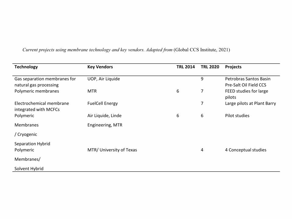
Technology Key Vendors TRL 2014 TRL 2020 Projects
Gas separation membranes for natural gas processing
UOP, Air Liquide 9 Petrobras Santos Basin Pre-Salt Oil Field CCS
Polymeric membranes MTR 6 7 FEED studies for large pilots
Electrochemical membrane integrated with MCFCs
FuelCell Energy 7 Large pilots at Plant Barry
Polymeric
Membranes
/ Cryogenic
Separation Hybrid
Air Liquide, Linde
Engineering, MTR
6 6 Pilot studies
Polymeric
Membranes/
Solvent Hybrid
MTR/ University of Texas 4 4 Conceptual studies
Current projects using membrane technology and key vendors. Adapted from (Global CCS Institute, 2021)

Membranes
Manufacturer Membrane Permeance [Barrer] CO2/N2 selectivity Polymer
Air Liquide Medal normalized 50 PI
Air Products PRISM™ 760 13 PSfMTR
Polaris™ gen 1 1000 50 PE-PA
Polaris™ gen 2 2000 49 PE-PA
Helmholtz-Zentrum PolyActive™ 1480 55 PEO-PBT
PermSelect PermSelect® 32.5 12 PDMS
Commercially available membrane modules tested with actual flue gas at pilot scale. Adapted from (Norahim, et al., 2018).

Questions to AskHow resistant is this material to :
H2O SO2NOxO2
Lots of people fail to consider the effects of species that are present in exhaust gases.
You don’t need to fund a million pound demonstration with “real” flue gas if people haven’t first tested their solvent at a lab scale. Bottled gas is a thing.

Adsorbents
CO2 preferentially (i.e. more than Nitrogen) bonds to a surface, and is then driven off at a higher temperature, or via the application of a vacuum.
Metal organic frameworks (MOFs) are large cage-like structures. Sometimes the MOFs are altered to allow more reaction sites with CO2.
Other types of adsorbent include carbon materials, frequently doped with amines. Generally, match something with a high surface area and something that reacts reversibly with CO2 and you are on to a winner.

Questions to AskWhat is the amount of CO2 that this material will adsorb per unit mass, and per unit volume? An ultra open structure is great, but you need to consider the size of the reactor required.
Have you done basic modelling of the system in e.g. Aspen, using isotherms you’ve measured at the lab scale?
Have you done basic order of magnitude costings?

Adsorbents
Svante VeloxoTherm™ process (top), rotary adsorbent bed (bottom left) and structured adsorbent (bottom right). Open access: (Webely, et al., 2017).

Ongoing research – new materials Supported amines on high-surface area solids Research drivers• potential to improve overall efficiency because they avoid
some of the thermal penalty associated with the use of aqueous-based amine systems
• commercially available solid amines used for many years for CO2 removal from closed environments, e.g. space shuttles and submarines
• a lot work done in the USA with funding from the US DOE/NETL, e.g., amines grafted onto high surface area zeolite supports
Technical challenges• limited testing with realistic gases• low capacity for CO2: The maximum CO2 capture capacity recently
reported was 0.132 g-CO2/g-sorbent (which reduces to about 0.101 g CO2/g under realistic conditions).
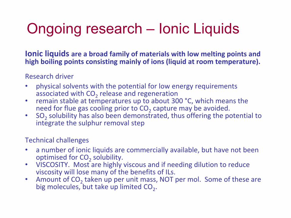
Ongoing research – Ionic LiquidsIonic liquids are a broad family of materials with low melting points and high boiling points consisting mainly of ions (liquid at room temperature).
Research driver • physical solvents with the potential for low energy requirements
associated with CO2 release and regeneration• remain stable at temperatures up to about 300 °C, which means the
need for flue gas cooling prior to CO2 capture may be avoided.• SO2 solubility has also been demonstrated, thus offering the potential to
integrate the sulphur removal step
Technical challenges• a number of ionic liquids are commercially available, but have not been
optimised for CO2 solubility.• VISCOSITY. Most are highly viscous and if needing dilution to reduce
viscosity will lose many of the benefits of ILs.• Amount of CO2 taken up per unit mass, NOT per mol. Some of these are
big molecules, but take up limited CO2.

Technology Key Vendors TRL 2014 TRL 2020 Projects
Pressure Swing
Adsorption/Vacuum
Swing Adsorption
Air Liquide, Air Products,
UOP
3 9 Air Products Port Arthur SMR CCS
Temperature Swing
Adsorption (TSA)
Svante 1 5-7 Large pilot tests to FEED studies for commercial plants
Enzyme Catalysed
Adsorption
CO2 solutions 1 6 Pilot demonstrations
Sorbent-Enhanced
Water Gas Shift
(SEWGS)
ECN 5 5 Pilot tests, like STEPWISE
Electrochemically
Mediated
Adsorption
R&D only 1 1 Lab tests
Current projects using adsorbent technology and key vendors. Adapted from (Global CCS Institute, 2021).
Adsorbents

Questions to AskWhat toxic elements are in this?
CRITICAL question for new materials
Brief scan of a review article shows new materials for CCS, based on Cd (toxic), bis(5-methyl-1H-1,2,4-triazol-3-yl)methane (complex to synthesize, expensive) and other environmentally damaging materials.
Chem. Soc. Rev., 2019, 48, 2783

Questions to AskHow resistant is this material to :
H2O SO2NOxO2
Lots of people fail to consider the effects of species that are present in exhaust gases.
You don’t need to fund a million pound demonstration with “real” flue gas if people haven’t first tested their solvent at a lab scale. Bottled gas is a thing.

Questions to AskThat benchmark you just gave… how recent was it?
Reproduced from DOI: 10.1039/C3EE42350F (Review Article) Energy Environ. Sci., 2014, 7, 130-189 with permission from The Royal Society of Chemistry

High temperature solid looping cycles
Use black magic wizardry to pay the thermodynamic penalty for demixing – so have “zero” energy penalty in a number of configurations (compression excluded).
Advantages: many
Disadvantages: noneDid I mention I’ve written a book on them?

But seriously…
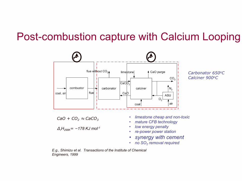
Post-combustion capture with Calcium Looping
• limestone cheap and non-toxic• mature CFB technology• low energy penalty• re-power power station• synergy with cement• no SO2 removal required
CaO + CO2 ⇋ CaCO3
∆rH298K= –178 KJ mol-1
E.g., Shimizu et al. Transactions of the Institute of Chemical Engineers, 1999
Carbonator 650oCCalciner 900oC
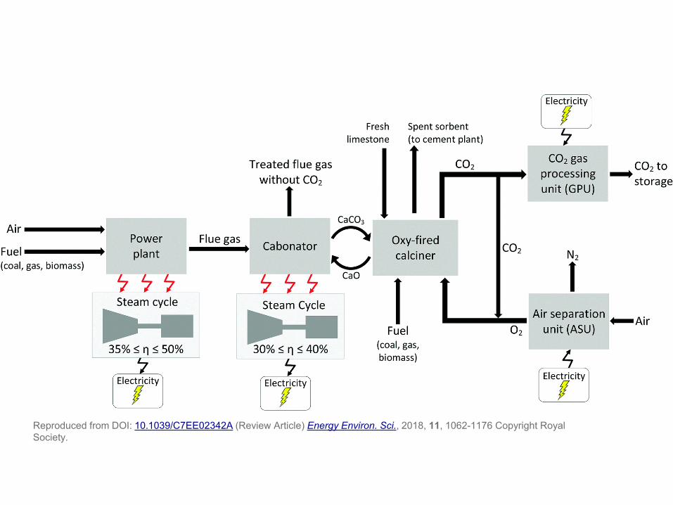
Reproduced from DOI: 10.1039/C7EE02342A (Review Article) Energy Environ. Sci., 2018, 11, 1062-1176 Copyright Royal Society.

Technical feasibility
1.7 MWth pilot taking slip stream from the Hunosa 50 MWe CFB coal power plant,"LaPereda“, Spain

Chemical Looping

Chemical looping combustion (CLC)
Reaction 1 Reaction 2
Rxn 1: 2𝑛𝑛 + 𝑚𝑚 𝑀𝑀𝑀𝑀𝑀𝑀 + 𝐶𝐶𝑛𝑛𝐻𝐻2𝑚𝑚 → 2𝑛𝑛 + 𝑚𝑚 𝑀𝑀𝑀𝑀 + 𝑚𝑚𝐻𝐻2𝑀𝑀 + 𝑛𝑛𝐶𝐶𝑀𝑀2Rxn 2: 𝑀𝑀𝑀𝑀 + 1
2𝑀𝑀2 → 𝑀𝑀𝑀𝑀𝑀𝑀
No N2!!
Fuel Reactor Oxidation Reactor
CO2 + H2O O2 deficient air
Air𝐶𝐶𝑛𝑛𝐻𝐻2𝑚𝑚
Me
MeO

• Fuel reactor- hydrocarbon fuel, CnH2m, reacted with oxygen carrier, reducing it to a pure metal or a lower form of the oxide; fuel is oxidised to CO2 and water vapour
• Flameless process• In general, Rxn 1 is endothermic, Rxn 2 is exothermic• This depends on the metal used, e.g., Fe- and Ni- are endothermic, Cu- is
exothermic• No direct fuel-air contact, so no N2 produced → CCS is integral to the
process
Chemical looping combustion (CLC)
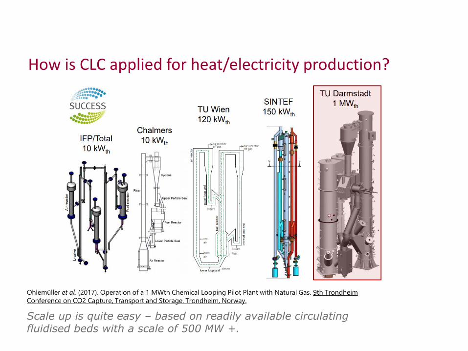
How is CLC applied for heat/electricity production?
Ohlemüller et al. (2017). Operation of a 1 MWth Chemical Looping Pilot Plant with Natural Gas. 9th Trondheim Conference on CO2 Capture, Transport and Storage. Trondheim, Norway.
Scale up is quite easy – based on readily available circulating fluidised beds with a scale of 500 MW +.

Questions to ask
• As with everything – “what’s in the material, has it been tested with realistic gases at small scale, and at the correct temperatures”
• How is this work an advance over the state of the art, have you done process modelling?

CCU
CO2 utilisation
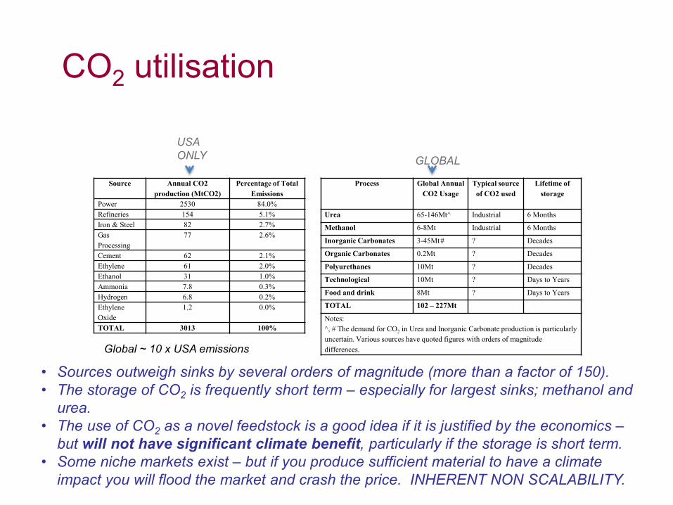
Source Annual CO2 production (MtCO2)
Percentage of Total Emissions
Power 2530 84.0%Refineries 154 5.1%Iron & Steel 82 2.7%Gas Processing
77 2.6%
Cement 62 2.1%Ethylene 61 2.0%Ethanol 31 1.0%Ammonia 7.8 0.3%Hydrogen 6.8 0.2%Ethylene Oxide
1.2 0.0%
TOTAL 3013 100%
Process Global Annual CO2 Usage
Typical source of CO2 used
Lifetime of storage
Urea 65-146Mt^ Industrial 6 Months
Methanol 6-8Mt Industrial 6 Months
Inorganic Carbonates 3-45Mt# ? Decades
Organic Carbonates 0.2Mt ? Decades
Polyurethanes 10Mt ? Decades
Technological 10Mt ? Days to Years
Food and drink 8Mt ? Days to Years
TOTAL 102 – 227Mt
Notes:^, # The demand for CO2 in Urea and Inorganic Carbonate production is particularly uncertain. Various sources have quoted figures with orders of magnitude differences.
USA ONLY GLOBAL
• Sources outweigh sinks by several orders of magnitude (more than a factor of 150).• The storage of CO2 is frequently short term – especially for largest sinks; methanol and
urea.• The use of CO2 as a novel feedstock is a good idea if it is justified by the economics –
but will not have significant climate benefit, particularly if the storage is short term.• Some niche markets exist – but if you produce sufficient material to have a climate
impact you will flood the market and crash the price. INHERENT NON SCALABILITY.
Global ~ 10 x USA emissions

CO2 utilisation• The annual CO2 emissions of an average power plant are on the order of 100 Mt, with
global emission on the order 32 Gt CO2 per year. • Typical CO2 injection and storage conditions are approximately 10 MPa and 40oC,
corresponding to a density of 600 – 700 kg/m3. • This corresponds to 108 m3/day or approximately 700,000,000 barrels per day. Current
global oil production is 90,000,000 barrels per day (in 2014). • This means that global CO2 production is approximately a factor of 10 greater than
global oil production.• Injecting CO2 for enhanced oil recovery (EOR) is well established and mature. However,
even this is relatively limited in scope. One can use approximately 0.3 tonne CO2 to produce 1 extra barrel of oil. In a UK context, there are approximately 24 billion barrels of oil remaining in the North Sea, equating to roughly 1-2 Gt capacity for CO2 injection for EOR, in idealised circumstances.
• Globally, current commercial CO2 utilisation processes only use 200 Mt of CO2 per year for chemicals manufacture. This means that we use ~ 0.6% of total global CO2produced. Therefore it is not realistic to consider CCU an alternative to CCS.
• Carbonation of waste materials to produce building products is a good idea.

CO2 utilisation
•CO2 is a very stable compound. It does not readily react with many other compounds – this is one of the reasons why CO2 persists in the atmosphere for so long once it has been emitted. •This means that the conversion of CO2 to high-value products is challenging and requires the input of energy.•It is vitally important that a rational carbon-accounting approach is taken when considering the utilisation of CO2 as opposed to storing CO2.•In comparing Capture and Utilisation (CCU) and CO2 Capture and Storage (CCS, it is important to distinguish between the long term, secure storage of CO2offered by CCS and the potentially short term utilisation of CO2 offered by some forms of CCU. Thus, CCU may not significantly impact global CO2atmospheric concentrations. •The decision, therefore, is not one of choosing between CCS and CCU, but rather which CCU option(s) best compliment CCS deployment targets associated with meeting our climate targets.

Conclusions
• CCS technologies are well understood and are considered mature. Improvements are likely, but even with current technology, we could deploy CCS today.
• Parallel development and deployment of future technologies is important – else we will be stuck with relatively poor choices.
• The choice between CCS and CCU is a false dichotomy. • CCU option(s) are only valuable to support CCS deployment
targets associated with meeting our climate targets.

Key References
• Mac Dowell et al., Energy and Environmental Science, 2010, 3, 1645-1669• Boot-Handford et al., Energy and Environmental Science, 2014, 7, 130-189• IPCC report “Climate Change 2013: The Physical Science Basis• Shackley and Gough, “Carbon Capture and its storage: an integrated assessment”,
2006• CCS Cost Reduction Taskforce, 2013. The potential for reducing the costs of CCS in the
UK - Final Report. [pdf] London: CCS Cost Reduction Taskforce. Available at: https://www.gov.uk/government/uploads/system/uploads/attachment_data/file/201021/CCS_Cost_Reduction_Taskforce_-_Final_Report_-_May_2013.pdf
• Department of Energy and Climate Change (DECC), 2012. CCS Roadmap - Supporting deployment of Carbon Capture and Storage in the UK. London: DECC. Available at: https://www.gov.uk/government/uploads/system/uploads/attachment_data/file/48317/4899-the-ccs-roadmap.pdf
• ClimateWise, 2012. Managing Liabilities of European Carbon Capture and Storage. Available at: http://www.climatewise.org.uk/storage/_website-2012/collaborations/ccs/ClimateWise%20CCS%20Report%20Nov%202012%20-%20Full%20Report.pdf