Beijing Huadu Center © Jangho Group...
25
JORDAHL ® Anchor Channels JXA Z-21.4-1690 Anchor Channels Valid until 1. April 2018 Beijing Huadu Center © Jangho Group Company REINFORCEMENT TECHNOLOGY CONNECTOR TECHNOLOGY FACADE CONNECTION SYSTEMS FASTENING TECHNOLOGY MOUNTING TECHNOLOGY
-
Upload
doannguyet -
Category
Documents
-
view
215 -
download
2
Transcript of Beijing Huadu Center © Jangho Group...

Jordahl® anchor Channels JXaZ-21.4-1690
Anchor Channels
Jordahl GmbhNobelstr. 5112057 Berlin
GermanyPhone +49 30 68283-02Fax +49 30 68283-497
Valid until 1. April 2018
Beijing Huadu Center © Jangho Group Company
REINFORCEMENT TECHNOLOGY CONNECTOR TECHNOLOGY FACADE
CONNECTION SYSTEMSFASTENING TECHNOLOGY MOUNTING TECHNOLOGY

FOR INFORMATION PURPOSES ONLY NOTIFICATION about the extension of the period of validity of the General Building Approval of 16th May 2012 GERMAN INSTITUTE FOR STRUCTURAL ENGINEERING (Deutsches Institut für Bautechnik DIBt) Public Institution
Telephone: 030 78730-0 Fax: 030 78730-320 E-Mail: [email protected]
Date: 24th March 2017 Office: I 23-1.21.4-99/16
Approval number: Z-21.4-1690 Client: JORDAHL GmbH Nobelstrasse 51 12057 Berlin Subject of the Approval: JORDAHL anchor channels type JXA W 29/20, JXA W 38/23 JXA W 53/34 and JXA W 64/44 Applicable: 1st April 2017 until 1st April 2018 The subject of the Approval mentioned above is hereby granted General Building Approval. This General Building Approval comprises ten pages and twelve annexes. Note: Translation of the German original version not checked by the German Institute for Structural Engineering Every page of the German original bears the official stamp of the German Institute for Structural Engineering
Z20429.15 1.21.4-96/14
ABOUT II SPECIAL PROVISIONS
The special provisions of the General Building Approval are amended as follows. a) The first sentence in Section 1.2 is replaced by the following sentence: The anchoring channel subject to static and quasi-static loading in reinforced normal weight
concrete and under fatigue-related central tensile load up to 2 × 10⁶ load cycles in reinforced normal concrete of strength grade of at least C12/15 according to DIN EN 206-1:2001-07 "Concrete; Part 1: Specification, performance, production and conformity" are used.
b) The first sentence in Section 3.2.7 is replaced by the following sentence: With regard to demands on fire resistance duration of concrete components, the anchor
channels may only be loaded perpendicularly to the channel axis (central tension, diagonal pull and shear load) in reinforced normal concrete of strength grade C12/15 under static and quasi-static loading.
c) In Appendix 6, Table 9, footnote 1 is replaced by the following footnote: The minimum distances specified in the table apply to reinforced concrete.

FOR INFORMATION PURPOSES ONLY NOTIFICATION about the amendment and extension of the period of validity of the General Building Approval of 16th May 2012 GERMAN INSTITUTE FOR STRUCTURAL ENGINEERING (Deutsches Institut für Bautechnik DIBt) Public Institution
Telephone: 030 78730-0 Fax: 030 78730-320 E-Mail: [email protected]
Date: 27th March 2015 Office: I 25-1.21.4-70/09
Approval number: Z-21.4-1690 Client: JORDAHL GmbH Nobelstrasse 51 12057 Berlin Subject of the Approval: JORDAHL anchor channels type JXA W 29/20, JXA W 38/23 JXA W 53/34 and JXA W 64/44 Applicable: 1st April 2015 until 1st April 2017 The subject of the Approval mentioned above is hereby granted General Building Approval. This General Building Approval comprises ten pages and twelve annexes. Note: Translation of the German original version not checked by the German Institute for Structural Engineering Every page of the German original bears the official stamp of the German Institute for Structural Engineering
Z20429.15 1.21.4-96/14
ABOUT II SPECIAL PROVISIONS
The special provisions of the General Building Approval are amended as follows. a) The first sentence in Section 1.2 is replaced by the following sentence: The anchoring channel subject to static and quasi-static loading in reinforced normal weight
concrete and under fatigue-related central tensile load up to 2 × 10⁶ load cycles in reinforced normal concrete of strength grade of at least C12/15 according to DIN EN 206-1:2001-07 "Concrete; Part 1: Specification, performance, production and conformity" are used.
b) The first sentence in Section 3.2.7 is replaced by the following sentence: With regard to demands on fire resistance duration of concrete components, the anchor
channels may only be loaded perpendicularly to the channel axis (central tension, diagonal pull and shear load) in reinforced normal concrete of strength grade C12/15 under static and quasi-static loading.
c) In Appendix 6, Table 9, footnote 1 is replaced by the following footnote: The minimum distances specified in the table apply to reinforced concrete.

Z487
36.1
1
FOR INFORMATION PURPOSES ONLY GERMAN INSTITUTE FOR STRUCTURAL ENGINEERING (Deutsches Institut für Bautechnik DIBt) Public Institution
Telephone: 030 78730-0 Fax: 030 78730-320 E-Mail: [email protected]
Date: 24th March 2010 Office: I 25-1.21.4-70/09
General Building Approval Approval number: Z-21.4-1690 Client: Deutsche Kahneisen Gesellschaft mbH Nobelstrasse 51 12057 Berlin Subject of the Approval: JORDAHL anchor channels type JXA-W 29/20, JXA-W 38/23 JXA-W 53/34 and JXA-W 64/44 Applicable until: 31st March 2015 The subject of the Approval mentioned above is hereby granted General Building Approval. * This General Building Approval comprises ten pages and twelve annexes. Note: Translation of the German original version not checked by the German Institute for Structural Engineering Every page of the German original bears the official stamp of the German Institute for Structural Engineering
I GENERAL PROVISIONS
1 With the General Building Approval, the usability and applicability of the subject of the Approval is verified in the sense of state building regulations.
2 Insofar as requirements are made within the General Building Approval on the special expertise and experience of the persons entrusted with the manufacture of structural products and building types according to § 17 Sec. 5 Model building code of corresponding country regulations, it is to be noted that this expertise and experience can be met by other equivalent means of proof of Member States of the European Union. This may also apply to equivalent proof submitted under the Agreement of the European Economic Area (EEA) or other bilateral agreements.
3 The General Building Approval does not replace the legally prescribed approvals, permits and certificates for the execution of construction projects.
4 The General Building Approval is granted irrespective of the rights of third parties, in particular private property rights.
5 Manufacturers and distributors of the subject of the Approval irrespective of further provisions in the "Special Provisions", have to provide the user of the approval object with copies of the General Building Approval available, pointing out that the General Building Approval must be at disposal at the application site. On request, the relevant authorities should be provided with copies of the General Building Approval.
6 The General Building Approval may only be reproduced in its entirety. Publication of excerpts requires the consent of the Deutsches Institut für Bautechnik. Texts and drawings of advertising material must not contradict the General Building Approval. Translations of the General Building Approval must contain the notice "translation of the original German version not checked by the Deutsches Institut für Bautechnik".
7 The General Building Approval is revocable. The provisions of the General Building Approval may be subsequently supplemented and amended, in particular if new technical findings make this necessary.

II SPECIAL PROVISIONS
1 Subject of Approval and field of application
1.1 Subject of Approval The JORDAHL anchor channel JXA (type W 29/20, type W 38/23, type W 53/34, type W 64/44) consisting of a C - shaped channel with teeth and at least two weld-on anchors arranged on profile backs or pressed round anchors of mill-finish steel in design or hot dip galvanised and in stainless steel. Hammer-head T-bolts or tooth bolts including respective nuts and washers are used in the channel, with which any construction parts can be fastened. The anchor channel is set flush with the surface in concrete. In Appendix 1, the anchor channel is shown in the installed state.
1.2 Area of application The anchoring channels may be used for anchorages under primarily static loading in reinforced or unreinforced normal concrete and under fatigue-related central tensile loading up to 2 106 load cycles in reinforced normal concrete of strength grade C12/15 according to DIN EN 206-1 "Concrete Part 1: Specification, performance, production and conformity" are used. For demands on the fire resistance duration of concrete structures in which the anchor channels are anchored, the restrictions as described in Section 3.2.7 must be observed. For fire exposure the anchor channel may only be loaded perpendicularly to the channel longitudinal axis. The anchor channel may also be used for anchorages primarily subject to static load in lightweight concrete with closed structure of strength grade of at least LC25/28 (aggregate of expanded clay, expanded shale or pumice) in accordance with DIN EN 206-1, provided that no demands are put on the overall construction including the anchor channel in terms of fire resistance duration. For anchoring in the tension zone of the concrete generated from load stresses or when utilising the minimum distances of the anchor channels, the local transverse tensile stresses occurring due to explosive effect must be absorbed by additional reinforcement, unless no structural measures or other favourable effects (e.g. shear pressure) prevent concrete from splitting. The areas of application of the anchor channel (channel profile, anchor, T-bolt, nut and washer) in regard to corrosion are to be specified with respect to the selected materials in Appendix 5, Table 7. A galvanised anchor channel (channel and anchor) may stand only in connection with reinforcement, when the temperature at the contact points between the reinforcement and the galvanised steel parts does not exceed 40°C. In pre-stressed concrete components the distance of a galvanised anchor channel (channel and anchor) must be at least 2 cm from the cladding tubes of the pre-stressed element or the pre-stressed wire with immediate bonding. When hot dip galvanised channels are used with stud anchors made of stainless steel, then the cladding tubes of the pre-stressed elements or the pre-stressed wires can be in connection with the T-bolts of stainless steel, but must not touch the hot dip galvanised channel.
2 Provisions for the structural product
2.1 Properties and composition The structural parts of the anchor channel (channel, anchor, T-bolt, nut and washer) must comply with the drawings and specifications of the equipment. The material characteristic values not specified in this General Building Approval must correspond to the specifications deposited with the Deutsches Institut für Bautechnik, and with the external monitoring unit information. In addition, the provisions of the General Building Approval Z-30.3-6 "Products, fasteners and structural components made of stainless steels" are to be observed.
2.2 Fabrication and labelling 2.2.1 Fabrication (connection channel/anchor)
The fabrication of the connections (welding, press-fitting) between the anchor and the channel has to take place at the factory. With regard to the verification of suitability of the welding operation DIN 18800-7:2008-11 "Steel Structures, Part 7 is valid: Execution and constructor's qualification". The round anchors are inserted and pressed in the factory through a prefabricated hole in the back of the channel.
2.2.2 Labelling Packaging, package inserts or delivery note of anchor channels and T-bolts must be labelled by the manufacturer with the conformity mark (Ü-mark) in accordance with the conformity mark regulations of the federal states. In addition, the identifying mark, the approval number and the full name of the anchor channels and T-bolts is to be specified on the delivery note. The marking may only be made if the conditions of Section 2.3 are met. The anchor channel is designated according to the outer dimensions of the rounded profile of the channel (width/height in mm), e.g. Profile JXA-W 38/23. The T-bolts are designated according to the bolt type (toothed T-bolt types JXD, JXH or JXB, hammer-head T-bolt types JD and JH) and the thread size and assigned to the profile dimensions. Each anchor channel must be identified in accordance with Appendix 5. The T-bolts have to be labelled and embossed according to Appendices 3 and 4.
2.3 Proof of Conformity 2.3.1 General
The confirmation of conformity of the anchor channels and T-bolts with the provisions of this General Building Approval must be carried out for each manufacturing plant with a declaration of conformity based on a factory production control and a regular external monitoring including an initial test of the anchor channels and T-bolts in accordance with the following provisions. For the issuance of the declaration of conformity and the external monitoring including the product inspections to be carried out, the manufacturer of the anchor channels and T-bolts has to consult with a recognised certification body and an approved monitoring body. The manufacturer shall hand over the statement that a declaration of conformity is issued by marking the structural products with the conformity mark (Ü mark) with a note on the intended use. The certification authority has to provide the Deutsches Institut für Bautechnik with a copy of the declaration of conformity they have issued, for information. The Deutsches Institut für Bautechnik is to be provided with an additional copy of the initial test report.
2.3.2 Factory production control A production control system is to be set up and operated in each manufacturing factory. Under factory production control, one understands the continuous monitoring of production that is established by the manufacturer, with which it ensures that the structural products the company manufacture comply with the provisions of this General Building Approval. For the scope, nature and frequency of factory production control the control plan deposited with the Deutsches Institut für Bautechnik and the external monitoring body shall prevail. The results of factory production control are to be recorded and evaluated. The records must contain at least the following information: - Designation of structural product or raw material and components - Type of control or testing - Date of manufacture and testing of the structural product or raw material or
components - Results of the control and tests and, if applicable, comparison with the requirements - Signature of the factory production control managers.

The records must be kept for at least five years and submitted to the appointed external monitoring body. They are presented to the Deutsches Institut für Bautechnik and to the responsible supreme construction supervision authority. In case of unsatisfactory test results, the manufacturer must immediately take the necessary measures to rectify the defect. Structural products which do not meet the requirements shall be handled such that confusions with conforming products are excluded. Once the defect is rectified, the remedial testing must be repeated immediately as far as it is technically possible and necessary.
2.3.3 External monitoring In each production works, the factory production control should be checked regularly by an external monitoring body, at least twice a year. As part of the external monitoring, an initial test of the anchor channels and T-bolts must be carried out and also samples must be taken for random sample testing. The sampling and tests are subject to the respective accredited monitoring body. For the scope, nature and frequency of external monitoring the control plan deposited with the Deutsches Institut für Bautechnik and the external monitoring body shall prevail. The results of certification and external monitoring must be kept for at least five years. Upon demand they have to be presented to the Deutsches Institut für Bautechnik and to the responsible supreme construction supervision authority by the certification body or by the monitoring body.
3 Provisions for design and dimensioning
3.1 Draft The anchorages shall be designed by an engineer. By considering the loads to be anchored, verifiable calculations and drawings are to be prepared. The drawings shall include details on location, size and length of the anchor channels and on the T-bolt type and the size of the corresponding bolts.
3.2 Dimensioning 3.2.1 General
The anchorages are to be dimensioned by an engineer. Proof of direct local force transfer into the concrete is provided. When verifying the anchor channel according to the partial safety factors, the design resistance FRd yields to 1.4 perm. F. The transfer of the loads to be anchored into the component must be verified. Weakening of concrete section by installing anchor channels is to be considered in static analysis, if necessary. Additional stresses that may arise in the anchor channel, in the component or in the part, in which the anchor channel is anchored, from disabled deformation (e.g. during temperature changes) are to be taken into account. The action of unit load or load pairs may take place at any point of the anchor channels. The axis and end distances of the load application points (T-bolts) are given in Appendices 7 and 8. The axis of the T-bolt must be at a distance of at least 25 mm from the channel end. The minimum distances of the anchor channels (axis, edge and corner distances) and component dimensions (component width and thickness) according to Appendix 6 must not be undershot.
3.2.2 Permissible loads The permissible loads of the anchor channels are indicated in Appendix 8, Table 11,
depending on the profile length, the load intervals and corresponding T-bolts for concrete strength grades C20/25.
For anchoring in concrete with the strength grade C12/15, permitted loads for C20/25 should be reduced by a factor of 0.7 and in lightweight concrete with closed structure LC25/28 by the factor 2/3. The permissible load directions (loading areas) for anchor channels are shown depending on the type of bolts in Appendix 7. When using the hammer-head T-bolt (types JD and JH) the anchor channel may be only loaded perpendicular to the channel longitudinal axis (shear load and central tension). When using the toothed T- bolt (types JXD, JXH and JXB) the
anchor channel may be loaded in all directions (longitudinal tension, lateral tension and central tension). With simultaneous stress in several directions, the resultant load must not exceed the permissible load according to Appendix 8, Table 11.
The permissible loads of the bolts are given in the Appendices 3 and 4. The smaller value (of anchor channel or T-bolt) shall prevail. 3.2.3 Bending stress of T-bolts
The permissible bending moments are indicated in the Appendices 3 and 4. The calculated clamping point is the top edge of the anchor channel. A bending stress may only be disregarded where - the component to be connected is made of metal and is braced without intermediate
position against the channel and - the through hole in the component to be connected, does not exceed the values in the
Appendices 3 and 4, Tables 4 and 6. For bending with additional central tension or diagonal pull, the stresses must be superimposed:
Fz ≤ perm. F (1 - M/perm M.) perm. F = permissible central tensile load of the T-bolt according to Appendices 3 and 4 perm. M = bending moment of the T-bolt according to Appendices 3 and 4
F z = existing tensile load component ≤ permissible load of the anchor channel (Appendix 8)
M = existing bending moment. In facade cladding with variable bending stresses (e.g. as a result of temperature changes) the stress amplitude σA = ± 50 N/mm² may not be exceeded by the mean value σM based on the calculated stress section of the T-bolt.
3.2.4 Fatigue relevant central tensile loads in reinforced normal concrete ≥ C12/15 For a stress load from fatigue-related central tensile loads with a number of load cycles
N ≤ 2106 the anchor JXA-W 29/20, JXA-W 38/23, JXA-W53/34 and JXA-W 64/44 may be used in the version with shear T-anchors and with round anchors. The permissible stress amplitude is specified for a number of load cycles N ≤ 2106 in Appendix 8, Table 12. The anchor channels may be anchored in reinforced normal concrete of at least C12/15. Only the corresponding T-bolts according to Appendix 8, Table 12 are allowed.
3.2.5 Special case of narrow reinforced concrete components An anchor channel arranged in the front face of at least 10 cm thick lightly loaded reinforced concrete structures (e.g. as facade panels, lightly-loaded traffic walls) may only be subjected to permissible central tensional load according to Appendix 8, Table 11, when an additional reinforcement is provided in accordance with Appendix 9.
3.2.6 Displacement behaviour Under allowable loading amount, the displacement of ≤ 0.6 mm can be expected towards the load: For shear loads, the existing hole clearance between T-bolt and component has to be additionally considered.
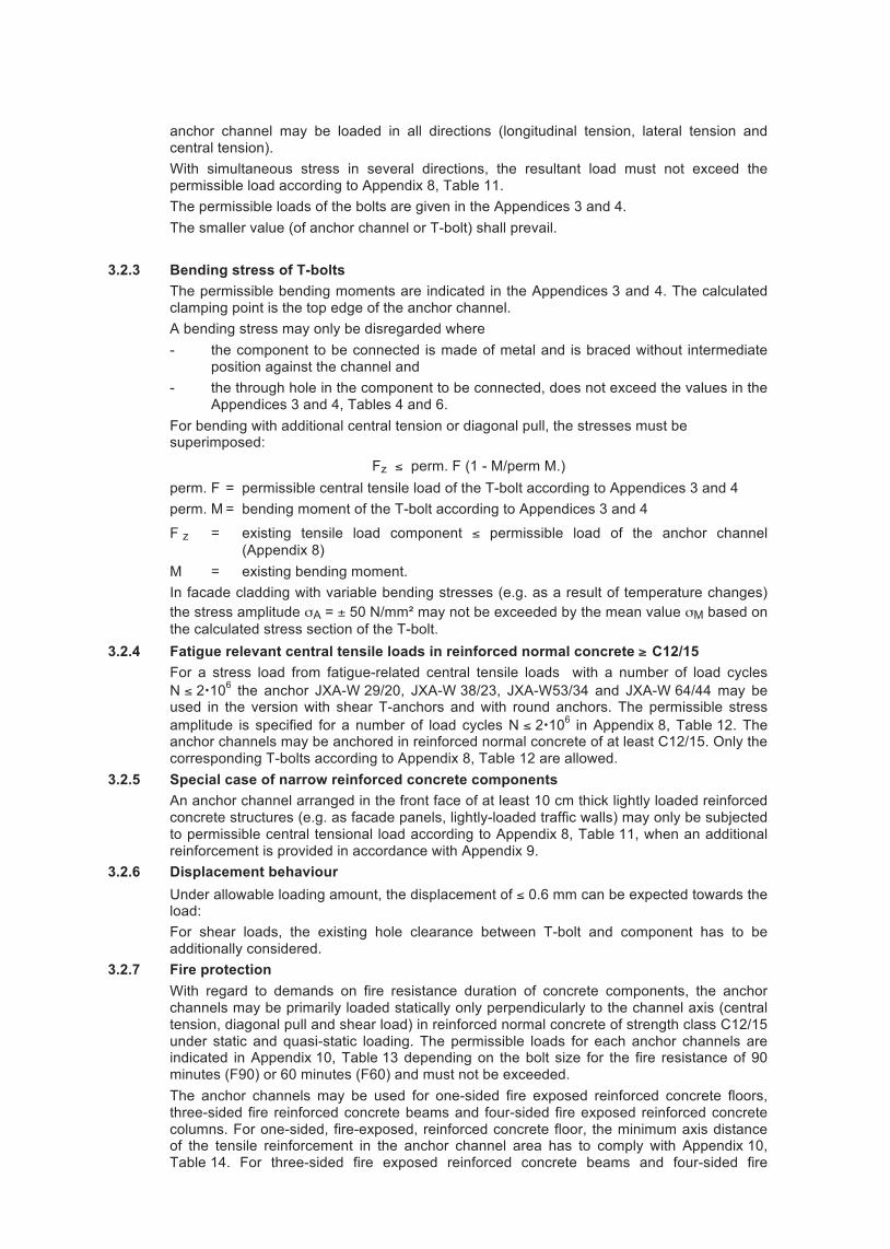
3.2.7 Fire protection With regard to demands on fire resistance duration of concrete components, the anchor channels may be primarily loaded statically only perpendicularly to the channel axis (central tension, diagonal pull and shear load) in reinforced normal concrete of strength class C12/15 under static and quasi-static loading. The permissible loads for each anchor channels are indicated in Appendix 10, Table 13 depending on the bolt size for the fire resistance of 90 minutes (F90) or 60 minutes (F60) and must not be exceeded. The anchor channels may be used for one-sided fire exposed reinforced concrete floors, three-sided fire reinforced concrete beams and four-sided fire exposed reinforced concrete columns. For one-sided, fire-exposed, reinforced concrete floor, the minimum axis distance of the tensile reinforcement in the anchor channel area has to comply with Appendix 10, Table 14. For three-sided fire exposed reinforced concrete beams and four-sided fire
The records must be kept for at least five years and submitted to the appointed external monitoring body. They are presented to the Deutsches Institut für Bautechnik and to the responsible supreme construction supervision authority. In case of unsatisfactory test results, the manufacturer must immediately take the necessary measures to rectify the defect. Structural products which do not meet the requirements shall be handled such that confusions with conforming products are excluded. Once the defect is rectified, the remedial testing must be repeated immediately as far as it is technically possible and necessary.
2.3.3 External monitoring In each production works, the factory production control should be checked regularly by an external monitoring body, at least twice a year. As part of the external monitoring, an initial test of the anchor channels and T-bolts must be carried out and also samples must be taken for random sample testing. The sampling and tests are subject to the respective accredited monitoring body. For the scope, nature and frequency of external monitoring the control plan deposited with the Deutsches Institut für Bautechnik and the external monitoring body shall prevail. The results of certification and external monitoring must be kept for at least five years. Upon demand they have to be presented to the Deutsches Institut für Bautechnik and to the responsible supreme construction supervision authority by the certification body or by the monitoring body.
3 Provisions for design and dimensioning
3.1 Draft The anchorages shall be designed by an engineer. By considering the loads to be anchored, verifiable calculations and drawings are to be prepared. The drawings shall include details on location, size and length of the anchor channels and on the T-bolt type and the size of the corresponding bolts.
3.2 Dimensioning 3.2.1 General
The anchorages are to be dimensioned by an engineer. Proof of direct local force transfer into the concrete is provided. When verifying the anchor channel according to the partial safety factors, the design resistance FRd yields to 1.4 perm. F. The transfer of the loads to be anchored into the component must be verified. Weakening of concrete section by installing anchor channels is to be considered in static analysis, if necessary. Additional stresses that may arise in the anchor channel, in the component or in the part, in which the anchor channel is anchored, from disabled deformation (e.g. during temperature changes) are to be taken into account. The action of unit load or load pairs may take place at any point of the anchor channels. The axis and end distances of the load application points (T-bolts) are given in Appendices 7 and 8. The axis of the T-bolt must be at a distance of at least 25 mm from the channel end. The minimum distances of the anchor channels (axis, edge and corner distances) and component dimensions (component width and thickness) according to Appendix 6 must not be undershot.
3.2.2 Permissible loads The permissible loads of the anchor channels are indicated in Appendix 8, Table 11,
depending on the profile length, the load intervals and corresponding T-bolts for concrete strength grades C20/25.
For anchoring in concrete with the strength grade C12/15, permitted loads for C20/25 should be reduced by a factor of 0.7 and in lightweight concrete with closed structure LC25/28 by the factor 2/3. The permissible load directions (loading areas) for anchor channels are shown depending on the type of bolts in Appendix 7. When using the hammer-head T-bolt (types JD and JH) the anchor channel may be only loaded perpendicular to the channel longitudinal axis (shear load and central tension). When using the toothed T- bolt (types JXD, JXH and JXB) the
anchor channel may be loaded in all directions (longitudinal tension, lateral tension and central tension). With simultaneous stress in several directions, the resultant load must not exceed the permissible load according to Appendix 8, Table 11.
The permissible loads of the bolts are given in the Appendices 3 and 4. The smaller value (of anchor channel or T-bolt) shall prevail. 3.2.3 Bending stress of T-bolts
The permissible bending moments are indicated in the Appendices 3 and 4. The calculated clamping point is the top edge of the anchor channel. A bending stress may only be disregarded where - the component to be connected is made of metal and is braced without intermediate
position against the channel and - the through hole in the component to be connected, does not exceed the values in the
Appendices 3 and 4, Tables 4 and 6. For bending with additional central tension or diagonal pull, the stresses must be superimposed:
Fz ≤ perm. F (1 - M/perm M.) perm. F = permissible central tensile load of the T-bolt according to Appendices 3 and 4 perm. M = bending moment of the T-bolt according to Appendices 3 and 4
F z = existing tensile load component ≤ permissible load of the anchor channel (Appendix 8)
M = existing bending moment. In facade cladding with variable bending stresses (e.g. as a result of temperature changes) the stress amplitude σA = ± 50 N/mm² may not be exceeded by the mean value σM based on the calculated stress section of the T-bolt.
3.2.4 Fatigue relevant central tensile loads in reinforced normal concrete ≥ C12/15 For a stress load from fatigue-related central tensile loads with a number of load cycles
N ≤ 2106 the anchor JXA-W 29/20, JXA-W 38/23, JXA-W53/34 and JXA-W 64/44 may be used in the version with shear T-anchors and with round anchors. The permissible stress amplitude is specified for a number of load cycles N ≤ 2106 in Appendix 8, Table 12. The anchor channels may be anchored in reinforced normal concrete of at least C12/15. Only the corresponding T-bolts according to Appendix 8, Table 12 are allowed.
3.2.5 Special case of narrow reinforced concrete components An anchor channel arranged in the front face of at least 10 cm thick lightly loaded reinforced concrete structures (e.g. as facade panels, lightly-loaded traffic walls) may only be subjected to permissible central tensional load according to Appendix 8, Table 11, when an additional reinforcement is provided in accordance with Appendix 9.
3.2.6 Displacement behaviour Under allowable loading amount, the displacement of ≤ 0.6 mm can be expected towards the load: For shear loads, the existing hole clearance between T-bolt and component has to be additionally considered.
3.2.7 Fire protection With regard to demands on fire resistance duration of concrete components, the anchor channels may be primarily loaded statically only perpendicularly to the channel axis (central tension, diagonal pull and shear load) in reinforced normal concrete of strength class C12/15 under static and quasi-static loading. The permissible loads for each anchor channels are indicated in Appendix 10, Table 13 depending on the bolt size for the fire resistance of 90 minutes (F90) or 60 minutes (F60) and must not be exceeded. The anchor channels may be used for one-sided fire exposed reinforced concrete floors, three-sided fire reinforced concrete beams and four-sided fire exposed reinforced concrete columns. For one-sided, fire-exposed, reinforced concrete floor, the minimum axis distance of the tensile reinforcement in the anchor channel area has to comply with Appendix 10, Table 14. For three-sided fire exposed reinforced concrete beams and four-sided fire

exposed reinforced concrete columns, the axial distance "u" of the reinforcement according to DIN 4102-4 is to be increased by the value "Δu" specified in the Appendices 11 and 12, Tables 15 and 16. If the anchor channels are installed in concrete components (reinforced concrete slabs, bars and columns) of fire resistance class F60 or F90 and the conditions specified in the Appendices 10 to 12 are complied with, the fire resistance class of the concrete is retained. The assessment of the fire resistance duration for the structure to be connected is not subject of this Approval.
4 Provisions for the implementation
4.1 Installation of anchor channels No anchors may be subsequently fixed nor other changes made to the anchor channel. The installation of the anchor channel must be made in accordance with design drawings in
Section 3.1.1. The anchor channels shall be attached to the formwork so that they do not move during
reinforcement installation or during introduction and compaction of concrete. The concrete must be compacted properly between the channels and under the head of the anchor. The anchor channels are to be protected against ingress of concrete into the channel cavity.
4.2 Mounting the connection construction (bolt mounting) The required bolt type and size is found in the design drawings. Under a load in the longitudinal direction of channel only the toothed T-bolt type JXD and type JXH may be used. This T-bolt is marked on the shaft end by two marking slots. If due to incorrect concrete introduction, etc., the front edge of the anchor channel is not flush with the concrete surface, this gap must be padded under the entire surface during installation of the connection structure. The heads of the T-bolts are inserted into the channel slot, must fully rest on both legs of the anchor channel after a clockwise rotation of 90° and be locked by tightening the nut with the torque wrench. The tightening torques specified in Appendices 3 and 4 must be complied with. After assembly, the correct seat of the T-bolt is to be checked, the marking slots on the shank end of the bolt must stand transversely to the longitudinal channel direction. The axial distance of the T-bolts (load distance) must not fall below the specifications of Appendix 7 and/or Appendix 8.
4.3 Control of the execution When installing the anchor channels and T-bolt installation (fastening of connection structures) the contractor entrusted with installing the anchor channels or the construction manager appointed by him or a proficient representative of the construction manager must be present on site. He is responsible for proper execution of work. In particular, he has to check the design and position of the anchor channels and the possibility of supplementary reinforcement. The records must be readily available for this purpose during construction on the site and upon demand they must be submitted to the monitoring officer. The records as well as the delivery notes must be kept by the contractor after the work, for at least 5 years.

General Building Approval No. Z-21.4-1690 dated
Channel length [mm]
Axial - and final distance of the anchor1)
[mm]
100
150
200
250
>250
W 29/20
W 38/23 W 53/34 W 64/44
1) The final distance in round anchors may be increased from 25 mm to 35 mm.
Component thickness h anchoring depth hef
JORDAHL® T-bolt
anchor element
Channel height h ch
Channel width bch
25
s ≤
200
(W 2
9/20
) s ≤
250
(W 3
8/23
) s ≤
250
(W 5
3/34
) s ≤
250
(W 6
4/44
)
≥ 25
Table 1: Anchoring arrangement
25 ≤ 250 25 25 25
25 ≤ 200 25
≤ 250 ≤ 250
25 25 ≤ 200 ≤ 200
25 200 25
25 150 25
25 100 25
25 50 25
Appendix 1
JORDAHL - anchor channel type JXA W 29/20, W38/23, W 53/34, W 64/44
Installed state Anchoring arrangement
General Building Approval No. Z-21.4-1690 dated
22.5
Profile
Anchor type Weld-on anchor Round Anchor Anch- oring depth
Min cut
length b
Head/ foot
width a1/a2
Web- thicknes
s t
Anchor position
Weld seam
position
Min weld- seam a/l
Shank- dia-
meter min d1
Head- dia-
meter min d2
min hef
hef
[mm] [mm] [mm] [mm]
W 29/20 R1 75 ― ― ― ― ― ― ― 9 17 I60 ― 75 12 18.5/18.5 5 Q/L Q/L 3/12 ― ―
W 38/23 R3 90 ― ― ― ― ― ― ― 10 19.5 I125 ― 143 18 20/25 5 Q/L Q/L 3/18 ― ― I128 ― 146 15 17/25 6 Q/L Q/L 3/14 ― ―
W 53/34 R3 155 ― ― ― ― ― ― ― 11.5 23.5 I128 ― 157 30 17/25 6 Q/L Q/L 3/30 ― ― I140 ― 164 30 20/40 7.1 Q/L Q/L 3/30 ― ―
W 64/44 R3 158 ― ― ― ― ― ― ― 15.5 28.0 I128 ― 167 40 17/25 6 Q/L Q/L 4/40 ― ― I140 ― 174 40 20/40 7.1 Q/L Q/L 4/40 ― ―
3(4)
Weld-on anchor type I
Round anchor type R
Ød2
Ød1 h ef
b
Weld seam position (L)
Anchor position, shear (Q)
a1
a2
t
h ef Weld seam
position (Q)
Anchor position, longitudinal (L)
Tooth pitch: Value in brackets for JXA W 64/44
Material profiles: S275JR (1.0044) according to DIN EN 10025 or stainless steel 1.4571/1.4404/1.4401 (A4) according to DIN EN 10088 and according to Z-30.3-6 Material T-anchor: S235JRG2 according to DIN EN 10025 or stainless steel 1.4571/1.4404/1.4401 (A4) according to DIN EN 10088 and according to Z-30.3-6 Material round anchor: QSt36 according to DIN EN 10263 or stainless steel 1.4571/1.4404/1.4401 (A4); according to DIN EN 10088 and according to Z-30.3-6
Table 2: Anchor
JXA – W 53/34 JXA – W 38/23 JXA – W 29/20 JXA – W 64/44
29
20
14
38
23
18
52.5
34
26
64
44
Appendix 2 Profile dimensions Anchor versions
JORDAHL - anchor channel type JXA W 29/20, W38/23, W 53/34, W 64/44

General Building Approval No. Z-21.4-1690 dated
22.5
Profile
Anchor type Weld-on anchor Round Anchor Anch- oring depth
Min cut
length b
Head/ foot
width a1/a2
Web- thicknes
s t
Anchor position
Weld seam
position
Min weld- seam a/l
Shank- dia-
meter min d1
Head- dia-
meter min d2
min hef
hef
[mm] [mm] [mm] [mm]
W 29/20 R1 75 ― ― ― ― ― ― ― 9 17 I60 ― 75 12 18.5/18.5 5 Q/L Q/L 3/12 ― ―
W 38/23 R3 90 ― ― ― ― ― ― ― 10 19.5 I125 ― 143 18 20/25 5 Q/L Q/L 3/18 ― ― I128 ― 146 15 17/25 6 Q/L Q/L 3/14 ― ―
W 53/34 R3 155 ― ― ― ― ― ― ― 11.5 23.5 I128 ― 157 30 17/25 6 Q/L Q/L 3/30 ― ― I140 ― 164 30 20/40 7.1 Q/L Q/L 3/30 ― ―
W 64/44 R3 158 ― ― ― ― ― ― ― 15.5 28.0 I128 ― 167 40 17/25 6 Q/L Q/L 4/40 ― ― I140 ― 174 40 20/40 7.1 Q/L Q/L 4/40 ― ―
3(4)
Weld-on anchor type I
Round anchor type R
Ød2
Ød1 h ef
b
Weld seam position (L)
Anchor position, shear (Q)
a1
a2
t
h ef Weld seam
position (Q)
aaAnchor position, longitudinal (L)
Tooth pitch: Value in brackets for JXA W 64/44
Material profiles: S275JR (1.0044) according to DIN EN 10025 or stainless steel 1.4571/1.4404/1.4401 (A4) according to DIN EN 10088 and according to Z-30.3-6 Material T-anchor: S235JRG2 according to DIN EN 10025 or stainless steel 1.4571/1.4404/1.4401 (A4) according to DIN EN 10088 and according to Z-30.3-6 Material round anchor: QSt36 according to DIN EN 10263 or stainless steel 1.4571/1.4404/1.4401 (A4); according to DIN EN 10088 and according to Z-30.3-6
Table 2: Anchor
JXA – W 53/34 JXA – W 38/23 JXA – W 29/20 JXA – W 64/44
29
20
14
38 23
18
52.5
34
26
64
44
Appendix 2 Profile dimensions Anchor versions
JORDAHL - anchor channel type JXA W 29/20, W38/23, W 53/34, W 64/44

General Building Approval No. Z-21.4-1690 dated
Profile Type [mm]
d [mm]
b1 [mm]
b2 [mm]
b3 [mm]
k [mm]
min l [mm]
JXA W 29/20 JXD M10 13.4 20.9 11.8 6.5 ≥ 15
M12 13.4 20.9 11.8 6.5 ≥ 20
JXA W 38/23 JXH M12 17.2 28.9 16.9 8.0 ≥ 20
M16 17.2 28.9 16.9 8.0 ≥ 30
JXA W 53/34 JXB M16 21.0 41.6 21.5 11.5 ≥ 30
M20 21.0 41.6 21.5 13.0 ≥ 35
JXA W 64/44 JXE M20 24.7 51.0 25.0 14 ≥ 35
M24 24.7 51.0 25.0 16 ≥ 40
Type
T-bolt diameter
d
[mm]
Through hole in component
to be connected
[mm]
Tightening torque
[Nm]
Perm. bending moment
of T-bolts 2) [Nm]
Perm. loads F [kN] 1) 3) (tension and shearing)
8.8 stainless Steel strength grade 70 8.8 stainless Steel
strength grade 70
JXD JXH
M10 12 40 24.9 18.7 13.3 8.7
M12 14 80 43.7 32.8 19.4 12.6
M16 18 120 111.0 83.3 36.1 23.6
JXB M16 18 200 111.0 83.3 36.1 23.6
M20 22 350 216.4 162.3 56.4 36.8
JXE M20 22 350 216.4 162.3 56.4 36.8
M24 26 450 513.1 359.4 81.2 67.9 1) Loading ranges, see Appendix 7. With simultaneous loading in all directions (longitudinal load - x, shear load - y, central
tension - z) the resultant load must not exceed the permissible loads in accordance with table. 2) Based on channels or concrete top edge 3) The permissible loads of the anchor channels according to Appendix 8 must not be exceeded.
Table 4: Permissible loads, torques and permissible bending moments of toothed T-bolts
Table 3: Bolt dimensions
Toothed T-bolts type JXD, JXH, JXB and JXE ― for load in all directions
T-bolts: Shank and thread form according to DIN EN ISO 4018,
¥ 8.8 fv according to DIN EN ISO 898-1 or ¥ stainless steel A4-70 (1.4571/1.4404/1.4401); F4-70 (1.4462) according to DIN EN ISO 3506-1 and Z-30.3-6
Hexagon nuts: Form in accordance with DIN EN ISO 4032 or DIN EN ISO 4034
¥ Strength grade 8 in accordance with DIN EN 20898-2 or stainless steel, strength grade 70 according to DIN EN ISO 3506-2 Washers: Form in accordance with DIN EN ISO 7089, DIN EN ISO 7093-1 product class A,
¥ steel according to DIN EN 10025 or ¥ stainless steel 1.4571/1.4404/1.4401 (A4) in accordance with DIN EN 10088 and Z-30.3-6
k l
d b2
b1
b3
Two notches as toothed T-bolt and for position identifier
Table 3: Bolt dimensionsEmbossing head: min. factory mark "J '', material abbreviation e.g.: "JXD 8.8 or JDX A4-70''
JORDAHL - anchor channel type JXA W 29/20, W38/23, W 53/34, W 64/44
Appendix 3 Toothed T-bolts JXD, JXH, JXB and JXE
General Building Approval No. Z-21.4-1690 dated
Profile Type [mm]
d [mm]
b1 [mm]
b2 [mm]
b3 [mm]
k [mm]
min l [mm]
JXA W 29/20 JD
M6 11.2 22.4 11.0 4.5 ≥ 15
M8 11.2 22.4 11.0 4.5 ≥ 15
M10 11.2 22.4 11.0 5.0 ≥ 20
M12 11.2 22.4 11.0 6.5 ≥ 20
JXA W 38/23 JH
M10 16.5 30.5 17.0 6.0 ≥ 20
M12 16.5 30.5 17.0 7.0 ≥ 20
M16 16.5 30.5 17.0 8.0 ≥ 30
Type
T-bolt diameter
d
[mm]
Through hole in component
to be connected
[mm]
Tightening torque
[Nm]
Perm. bending moment
of T-bolts 2) [Nm]
Perm. loads F [kN] 1) 3) (tension and shearing)
4.6 A4-50 A4-70 4.6 A4-50 A4-70
JD JH
M6 7 3 2.0 1.8 3.8 2.2 2.2 3.0
M8 9 8 5.0 4.4 9.4 4.0 4.0 5.5
M10 12 15 10.0 8.7 18.7 6.4 6.4 8.7
M12 14 25 17.5 15.3 32.8 9.3 9.3 12.6
M16 18 60 44.0 38.8 83.3 17.3 17.3 23.6
Hammer-head T-bolts type JD and JH ⎯ for load on tension, shear load, diagonal pull
1) Loading ranges, see Appendix 7. With simultaneous tension in the directions (shear load - y, and diagonal pull, central tension - z) the resultant load must not exceed the permissible loads in accordance with table.
2) Based on channels or concrete top edge 3) The permissible loads of the anchor channels according to Appendix 8 must not be exceeded.
Table 6: Permissible loads, tightening torque and permissible bending moments of hammer-head T-bolts
Table 5: Bolt dimensions Embossing head. min works sign "J'', material abbreviation e.g.: "JD 4.6 or JD A4''
k
d b2
b3
b 1
l
Notch for position identifier
Appendix 4 Hammer-head T-bolts JD and JH
JORDAHL - anchor channel type JXA W 29/20, W38/23, W 53/34, W 64/44
T-bolts: Shank and thread form according to DIN EN ISO 4018,
¥ 4.6 or 8.8 according to DIN EN ISO 898-1 or ¥ stainless steel A4-50, A4-70 (1.4571/1.4404/1.4401); F4-50, F4-70 (1.4462) according to DIN EN ISO 3506-1 and Z-30.3-6
Hexagon nuts: Form in accordance with DIN EN ISO 4032 or DIN EN ISO 4034
¥ Strength grade 5 or 8 according to DIN EN 20898-2 or stainless steel, strength grade 50 or 70 in accordance with DIN EN ISO 3506-2
Washers: Form in accordance with DIN EN ISO 7089, DIN EN ISO 7093-1 product class A,
¥ steel according to DIN EN 10025 or ¥ stainless steel 1.4571/1.4404/1.4401 (A4) in accordance with DIN EN 10088 and Z-30.3-6

General Building Approval No. Z-21.4-1690 dated
Structural parts
Area of application Channel Anchor T-bolt, nut, washer
1 mill finish mill finish without corrosion protection
Use only possible when all the fasteners depending on the ambient conditions are protected by a minimum concrete cover according to DIN 1045 -1:2008-08, Table 4 or DIN EN 1992-1-1:2011-01 with DIN EN 1992-1-1/NA:2011-01, Section 4.4.
2
hot dip galvanised/
HDG (≥ 50 µm)
hot dip galvanised/ HDG
(≥ 50 µm)
electro zinc plated (≥ 5 µm)
Components in enclosed spaces, such as homes, offices, schools, hospitals, retail outlets - with the exception of wet rooms
3
hot dip galvanised/
HDG (≥ 50 µm)
hot dip galvanised/ HDG
(≥ 50 µm)
hot dip galvanised/ HDG
(≥ 40 µm)
Components in interior rooms with normal humidity (incl. kitchen, bathroom and laundry room in residential buildings)
4 stainless steel
1.4571 1.4401 1.4404
Weld-on anchor, mill finish 1)
Stainless steel 1.4571/1.4404/1.4401
Strength grade 50 or 70
Components according to the corrosion resistance class III/medium according Z-30.3-6 for example, in damp rooms, outdoors, industrial atmosphere, close to the sea and inaccessible constructions
stainless Steel 1.4571 1.4401 1.4404
Profile JXA existing concrete cover c
of weld-on anchor [mm]
W 38/23 30 W 53/34 40 W 64/44 50
Table 7: Areas of application depending on the corrosion protection
1) Only permitted for profile 38/23, 53/34 and 64/44. With regard to the corrosion protection of weld-on anchor the concrete cover c may be used as a basis in accordance with Table 8.
Table 8: Concrete cover of weld-on anchor
Identification The anchor channels are to be marked permanently on the back of the channel, laterally on the channel web or on the anchor. It can be done by printing, embossing or other appropriate means. Minimum requirement: Profile specification, upon execution of stainless steel additional material specification).
c
e.g.: JXA - W 38/23 – A4
Appendix 5 Corrosion protection and application areas
Identification
JORDAHL - anchor channel type JXA W 29/20, W38/23, W 53/34, W 64/44
JXA W38/23 A4
General Building Approval No. Z-21.4-1690 dated
Minimum distances and minimum dimensions [mm] 1)
Profile JXA ar aa ae af b 2) h 3) Channel pairs 4) ar1 aa1
W 29/20 100 200 80 200 200 140 125 W 38/23 150 300 130 250 300 225 150 W 53/34 200 400 175 350 400 ⎯ ⎯ W 64/44 250 500 225 450 500 ⎯ ⎯
Table 9: Minimum distances and minimum dimensions for all concrete strength grades
1) The minimum distances specified in the table apply to reinforced concrete. With enlargement of the distances by 30% no requirements are placed on the reinforcement.
2) Applies when a channel is used. 3) Results from the length of the anchor and the required concrete cover according to DIN 1045-1: 2008-08 or DIN
EN 1992-1-1:2011-01 with DIN EN 1992-1-1/NA:2011-01, Section 4.4. 4) Permissible only for central tension.
Appendix 6 Axial and edge distances
JORDAHL - anchor channel type JXA W 29/20, W38/23, W 53/34, W 64/44
Pairs of Channels

General Building Approval No. Z-21.4-1690 dated
Hammer-head T-bolts JD and JH Tension perpendicular to the channel
longitudinal axis (shear load y, central tension z)
Toothed T-bolts type JXD, JXH, JXB and JXE Loading in all directions (Longitudinal load x, y
shear load, central tension z)
FFyFz zul≤+ ²² F²Fy²Fz²Fx zul≤++
The resultant load must not exceed the permissible loads according to Appendix 8, Table 11.
Unit loads Last couple
Table 10: Tension areas depending on the type of T-bolt
Load arrangement
1) ≥100mm in JXA W53/34 and W 64/44 profile
Appendix 7 Loading areas
Load arrangement
1) 1) 1)
JORDAHL - anchor channel type JXA W 29/20, W38/23, W 53/34, W 64/44
Pairs of loads
General Building Approval No. Z-21.4-1690 dated
1) For anchoring in concrete with the strength grade C 12/15 the permitted loads for C 20/25 should be reduced by a factor of 0.7 and in lightweight concrete with closed structure ≥ LC 25/28 by the factor 2/3.
2) With simultaneous loading in several directions (see Appendix 7, Table 10) the resultant load must not exceed the permissible loads in accordance with Table 11.
3) Loading areas see Appendix 7, Table 10. 4) Hammer-head T-bolts type JD and JH are not approved for loads in the longitudinal channel direction (x-x). When
using smaller T-bolts type JD and JH in Appendix 4, the permissible load of the T-bolt in accordance with Appendix 4, Table 6 must not be exceeded.
5) Intermediate values may be interpolated. 6) The value in brackets applies to profiles from A4. 7) The minimum distance for load profile JXA W 53/34 and W 64/44 is 100 mm.
Round anchor or T-anchor position, shear/
Weld seam, shear Q/Q
The stress amplitudes are valid for profiles with round anchors or shear T-anchors. For the profile 53/34 and 64/44 the weld position in the T-anchors must be observed.
Profile JXA
Associated T-bolt Permissible loads F [kN] 2)3)
Loading areas in all load directions
Hammer-head T-bolts 4) Toothed T-bolts Unit load Last couple
Profile length [mm] ≥ 100 ≥ 200 Load distance [mm] ≥ 250 ≥ 50 ≥ 150
W 29/20 JD M12 JXD M10
8 4.5 5) 6.4 5) JXD M12
W 38/23 JH M16 JXH M12
12 6.7 5) 8.6 5) JXH M16
W 53/34 ⎯ JXB M16
22 (19) 6) ⎯ 13.75 7) JXB M20
W 64/44 ⎯ JXE M20
27 ⎯ 16.0 7) JXB M24
Profile JXA
Permissible stress amplitude ΔF under tension ΔF = Fo - Fu [kN]
Permissible T-bolts
Steel, fv stainless steel (A4)
W 29/20 2 1.8 JXD M12 JD M12
W 38/23 3 2.4 JXH M16 JH M16
W 53/34 W 53/34
6 (Q/Q) 4 (Q/Q) JXB M16 JXB M20 12 (Q/L) 10 (Q/L)
W 64/44 W 64/44
7 (Q/Q) --- JXE M20 JXE M24 15 (Q/L) 11 (Q/L)
Appendix 8 Permissible loads Permissible amplitude factor
Table 11: Permissible loads of anchor channels for all concrete strength grades ≥ C20/25 1)
Table 12: Not predominantly static central tensile loads Permissible stress amplitudes for a number of load cycles N ≤ 2x10⁶
perm. F (statically permissible load) = 22.0 kN
The application is permissible only in reinforced components. When installed in a zone of reinforced concrete components under tension generated from the load stress, the line of action of forces must be verified.
T-anchor position, shear/ Weld seam, longitudinal
Q/L
JORDAHL - anchor channel type JXA W 29/20, W38/23, W 53/34, W 64/44
Table 12: Not predominantly static centric tensile loads (perm. stress amplitudes for a number of load cycles N ≤ 2x10⁶)
4)
Example: JXA W 53/34 (St) perm. F (static. permissible load) = 22.0 kN perm. ΔF (threshold tension) = - 6.0 kN remaining tension = 16.0 kN

General Building Approval No. Z-21.4-1690 dated
1) For anchoring in concrete with the strength grade C 12/15 the permitted loads for C 20/25 should be reduced by a factor of 0.7 and in lightweight concrete with closed structure ≥ LC 25/28 by the factor 2/3.
2) With simultaneous loading in several directions (see Appendix 7, Table 10) the resultant load must not exceed the permissible loads in accordance with Table 11.
3) Loading areas see Appendix 7, Table 10. 4) Hammer-head T-bolts type JD and JH are not approved for loads in the longitudinal channel direction (x-x). When
using smaller T-bolts type JD and JH in Appendix 4, the permissible load of the T-bolt in accordance with Appendix 4, Table 6 must not be exceeded.
5) Intermediate values may be interpolated. 6) The value in brackets applies to profiles from A4. 7) The minimum distance for load profile JXA W 53/34 and W 64/44 is 100 mm.
Round anchor or T-anchor position, shear/
Weld seam, shear Q/Q
The stress amplitudes are valid for profiles with round anchors or shear T-anchors. For the profile 53/34 and 64/44 the weld position in the T-anchors must be observed.
Profile JXA
Associated T-bolt Permissible loads F [kN] 2)3)
Loading areas in all load directions
Hammer-head T-bolts 4) Toothed T-bolts Unit load Last couple
Profile length [mm] ≥ 100 ≥ 200 Load distance [mm] ≥ 250 ≥ 50 ≥ 150
W 29/20 JD M12 JXD M10
8 4.5 5) 6.4 5) JXD M12
W 38/23 JH M16 JXH M12
12 6.7 5) 8.6 5) JXH M16
W 53/34 ⎯ JXB M16
22 (19) 6) ⎯ 13.75 7) JXB M20
W 64/44 ⎯ JXE M20
27 ⎯ 16.0 7) JXB M24
Profile JXA
Permissible stress amplitude ΔF under tension ΔF = Fo - Fu [kN]
Permissible T-bolts
Steel, fv stainless steel (A4)
W 29/20 2 1.8 JXD M12 JD M12
W 38/23 3 2.4 JXH M16 JH M16
W 53/34 W 53/34
6 (Q/Q) 4 (Q/Q) JXB M16 JXB M20 12 (Q/L) 10 (Q/L)
W 64/44 W 64/44
7 (Q/Q) --- JXE M20 JXE M24 15 (Q/L) 11 (Q/L)
Appendix 8 Permissible loads Permissible amplitude factor
Table 11: Permissible loads of anchor channels for all concrete strength grades ≥ C20/25 1)
Table 12: Not predominantly static central tensile loads Permissible stress amplitudes for a number of load cycles N ≤ 2x10⁶
perm. F (statically permissible load) = 22.0 kN
The application is permissible only in reinforced components. When installed in a zone of reinforced concrete components under tension generated from the load stress, the line of action of forces must be verified.
T-anchor position, shear/ Weld seam, longitudinal
Q/L
JORDAHL - anchor channel type JXA W 29/20, W38/23, W 53/34, W 64/44
Table 12: Not predominantly static centric tensile loads (perm. stress amplitudes for a number of load cycles N ≤ 2x10⁶)
4)
Round anchor or T-anchor position, shear/
Example: JXA W 53/34 (St) perm. F (static. permissible load) = 22.0 kN perm. ΔF (threshold tension) = - 6.0 kN remaining tension = 16.0 kN
upper loadlower load
1 load cycle
General Building Approval No. Z-21.4-1690 dated
1) For anchoring in concrete with the strength grade C 12/15 the permitted loads for C 20/25 should be reduced by a factor of 0.7 and in lightweight concrete with closed structure ≥ LC 25/28 by the factor 2/3.
2) With simultaneous loading in several directions (see Appendix 7, Table 10) the resultant load must not exceed the permissible loads in accordance with Table 11.
3) Loading areas see Appendix 7, Table 10. 4) Hammer-head T-bolts type JD and JH are not approved for loads in the longitudinal channel direction (x-x). When
using smaller T-bolts type JD and JH in Appendix 4, the permissible load of the T-bolt in accordance with Appendix 4, Table 6 must not be exceeded.
5) Intermediate values may be interpolated. 6) The value in brackets applies to profiles from A4. 7) The minimum distance for load profile JXA W 53/34 and W 64/44 is 100 mm.
Round anchor or T-anchor position, shear/
Weld seam, shear Q/Q
The stress amplitudes are valid for profiles with round anchors or shear T-anchors. For the profile 53/34 and 64/44 the weld position in the T-anchors must be observed.
Profile JXA
Associated T-bolt Permissible loads F [kN] 2)3)
Loading areas in all load directions
Hammer-head T-bolts 4) Toothed T-bolts Unit load Last couple
Profile length [mm] ≥ 100 ≥ 200 Load distance [mm] ≥ 250 ≥ 50 ≥ 150
W 29/20 JD M12 JXD M10
8 4.5 5) 6.4 5) JXD M12
W 38/23 JH M16 JXH M12
12 6.7 5) 8.6 5) JXH M16
W 53/34 ⎯ JXB M16
22 (19) 6) ⎯ 13.75 7) JXB M20
W 64/44 ⎯ JXE M20
27 ⎯ 16.0 7) JXB M24
Profile JXA
Permissible stress amplitude ΔF under tension ΔF = Fo - Fu [kN]
Permissible T-bolts
Steel, fv stainless steel (A4)
W 29/20 2 1.8 JXD M12 JD M12
W 38/23 3 2.4 JXH M16 JH M16
W 53/34 W 53/34
6 (Q/Q) 4 (Q/Q) JXB M16 JXB M20 12 (Q/L) 10 (Q/L)
W 64/44 W 64/44
7 (Q/Q) --- JXE M20 JXE M24 15 (Q/L) 11 (Q/L)
Appendix 8 Permissible loads Permissible amplitude factor
Table 11: Permissible loads of anchor channels for all concrete strength grades ≥ C20/25 1)
Table 12: Not predominantly static central tensile loads Permissible stress amplitudes for a number of load cycles N ≤ 2x10⁶
perm. F (statically permissible load) = 22.0 kN
The application is permissible only in reinforced components. When installed in a zone of reinforced concrete components under tension generated from the load stress, the line of action of forces must be verified.
T-anchor position, shear/ Weld seam, longitudinal
Q/L
JORDAHL - anchor channel type JXA W 29/20, W38/23, W 53/34, W 64/44
Table 12: Not predominantly static centric tensile loads (perm. stress amplitudes for a number of load cycles N ≤ 2x10⁶)
Example: JXA W 53/34 (St) perm. F (static. permissible load) = 22.0 kN perm. ΔF (threshold tension) = - 6.0 kN remaining tension = 16.0 kN

General Building Approval No. Z-21.4-1690 dated
≥ lb,net DIN 1045-1:2008-08 or ≥ lbd according to DIN EN 1992-1-1:2011-01 with DIN EN 1992-1-1/NA:2011-01
As (B500B) with dBr or øm,min smallest permissible bending roller diameter
Reduced edge distance in load on train and provision of an additional reinforcement according to section 3.2.5 for profiles 29/20 and W 38/23
2x ≥ Ø6 B500B
Section A-A
Plan view
attachable steel tension σs = 8 kN/cm² req As [cm²] = reinforcement cross-section of a loop leg permF = maximum load in accordance with Appendix 8, Table 11
Appendix 9 Supplementary reinforcement with reduced edge distance
JORDAHL - anchor channel type JXA W 29/20, W38/23, W 53/34, W 64/44
General Building Approval No. Z-21.4-1690 dated
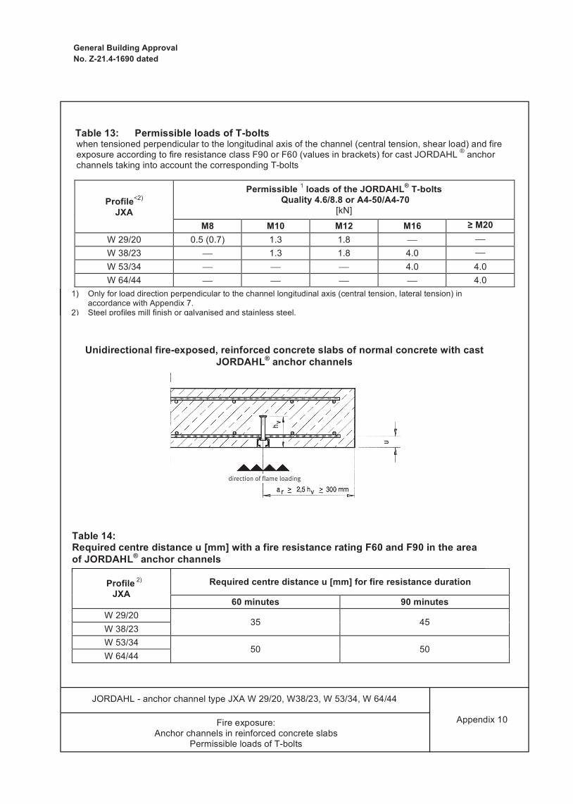
Profile<2) JXA
Permissible 1 loads of the JORDAHL® T-bolts Quality 4.6/8.8 or A4-50/A4-70
[kN]
M8 M10 M12 M16 ≥ M20 W 29/20 0.5 (0.7) 1.3 1.8 ⎯ ⎯ W 38/23 ⎯ 1.3 1.8 4.0 ⎯ W 53/34 ⎯ ⎯ ⎯ 4.0 4.0 W 64/44 ⎯ ⎯ ⎯ ⎯ 4.0
Profile 2) JXA
Required centre distance u [mm] for fire resistance duration
60 minutes 90 minutes W 29/20
35 45 W 38/23 W 53/34
50 50 W 64/44
Table 13: Permissible loads of T-bolts when tensioned perpendicular to the longitudinal axis of the channel (central tension, shear load) and fire exposure according to fire resistance class F90 or F60 (values in brackets) for cast JORDAHL ® anchor channels taking into account the corresponding T-bolts
1) Only for load direction perpendicular to the channel longitudinal axis (central tension, lateral tension) in accordance with Appendix 7.
2) Steel profiles mill finish or galvanised and stainless steel.
Table 14: Required centre distance u [mm] with a fire resistance rating F60 and F90 in the area of JORDAHL® anchor channels
Unidirectional fire-exposed, reinforced concrete slabs of normal concrete with cast JORDAHL® anchor channels
Appendix 10 Fire exposure: Anchor channels in reinforced concrete slabs
Permissible loads of T-bolts
JORDAHL - anchor channel type JXA W 29/20, W38/23, W 53/34, W 64/44
General Building Approval No. Z-21.4-1690 dated
Profile<2) JXA
Permissible 1 loads of the JORDAHL® T-bolts Quality 4.6/8.8 or A4-50/A4-70
[kN]
M8 M10 M12 M16 ≥ M20 W 29/20 0.5 (0.7) 1.3 1.8 ⎯ ⎯ W 38/23 ⎯ 1.3 1.8 4.0 ⎯ W 53/34 ⎯ ⎯ ⎯ 4.0 4.0 W 64/44 ⎯ ⎯ ⎯ ⎯ 4.0
Profile 2) JXA
Required centre distance u [mm] for fire resistance duration
60 minutes 90 minutes W 29/20
35 45 W 38/23 W 53/34
50 50 W 64/44
Table 13: Permissible loads of T-bolts when tensioned perpendicular to the longitudinal axis of the channel (central tension, shear load) and fire exposure according to fire resistance class F90 or F60 (values in brackets) for cast JORDAHL ® anchor channels taking into account the corresponding T-bolts
1) Only for load direction perpendicular to the channel longitudinal axis (central tension, lateral tension) in accordance with Appendix 7.
2) Steel profiles mill finish or galvanised and stainless steel.
Table 14: Required centre distance u [mm] with a fire resistance rating F60 and F90 in the area of JORDAHL® anchor channels
Unidirectional fire-exposed, reinforced concrete slabs of normal concrete with cast JORDAHL® anchor channels
Appendix 10 Fire exposure: Anchor channels in reinforced concrete slabs
Permissible loads of T-bolts
JORDAHL - anchor channel type JXA W 29/20, W38/23, W 53/34, W 64/44
direction of fl ame loading

General Building Approval No. Z-21.4-1690 dated
Profile JXA
Δu 1) [mm] for F90 based on beam width
b = 150 mm b = 250 mm b = 300 mm b ≥ 400 mm W 29/20
15 10 10 10 W 38/23 W 53/34 20 15 15 15 W 64/44 35 25 20 15
Three-sided fire exposed reinforced concrete beams made of normal concrete Load of anchor channel only permitted perpendicular to the channel longitudinal axis of central and lateral
tension in accordance with Appendix 7.
1) Intermediate values may be interpolated linearly.
Table 15: Enlargement of the centre distance u [mm] of the tensile reinforcement The centre distances u or us required according to DIN 4102-4:1994-03 are to be increased during installation of anchor channels by the magnitude Δ.
Appendix 11 Fire exposure:
Anchor channels in reinforced concrete beams
JORDAHL - anchor channel type JXA W 29/20, W38/23, W 53/34, W 64/44
General Building Approval No. Z-21.4-1690 dated
Profile JXA
Δ u 1) [mm] for F90 based on support cross-section of
b = 180 mm 2) b = 210 mm 3) b = 240 mm b = 300 mm b ≥ 400 mm W 29/20
15 10 10 10 10 W 38/23 W 53/34 20 15 15 15 15 W64/44 35 25 20 15 15
Four-sided fire exposed reinforced concrete columns made of normal concrete Load of anchor channel only permitted perpendicular to the channel longitudinal axis of central and lateral
tension in accordance with Appendix 7.
1) Intermediate values may be interpolated linearly. 2) Utilisation factor α1 under Section 3.13.2.2 DIN 4102-4 ≤ 0.3 3) Utilisation factor α1 under Section 3.13.2.2 DIN 4102-4 ≤ 0.73
Table 16: Enlargement of the centre distance u [mm] of the reinforcing steel by Δu The centre distances u or us required according to DIN 4102-4:1994-03 are to be increased during installation of anchor channels by the magnitude Δ.
*) bmin and hmin: ≥ 180 mm at α1 < 0.3 ≥ 210 mm at α1 < 0.7 ≥ 240 mm at α1 < 1.0 α1 according to DIN 4102-4:1994-03, Table 31
Appendix 12 Fire exposure:
Anchor channels in reinforced concrete columns
JORDAHL - anchor channel type JXA W 29/20, W38/23, W 53/34, W 64/44
dire
ctio
n of
fl am
e lo
adin
g
The arrangement of theanchor channel on all threesides is also possible.

General Building Approval No. Z-21.4-1690 dated
Profile JXA
Δ u 1) [mm] for F90 based on support cross-section of
b = 180 mm 2) b = 210 mm 3) b = 240 mm b = 300 mm b ≥ 400 mm W 29/20
15 10 10 10 10 W 38/23 W 53/34 20 15 15 15 15 W64/44 35 25 20 15 15
Four-sided fire exposed reinforced concrete columns made of normal concrete Load of anchor channel only permitted perpendicular to the channel longitudinal axis of central and lateral
tension in accordance with Appendix 7.
1) Intermediate values may be interpolated linearly. 2) Utilisation factor α1 under Section 3.13.2.2 DIN 4102-4 ≤ 0.3 3) Utilisation factor α1 under Section 3.13.2.2 DIN 4102-4 ≤ 0.73
1)
Table 16: Enlargement of the centre distance u [mm] of the reinforcing steel by Δu The centre distances u or us required according to DIN 4102-4:1994-03 are to be increased during installation of anchor channels by the magnitude Δ.
*) bmin and hmin: ≥ 180 mm at α1 < 0.3 ≥ 210 mm at α1 < 0.7 ≥ 240 mm at α1 < 1.0 α1 according to DIN 4102-4:1994-03, Table 31
Appendix 12 Fire exposure:
Anchor channels in reinforced concrete columns
JORDAHL - anchor channel type JXA W 29/20, W38/23, W 53/34, W 64/44
Defi n
e in
Vie
w o
f Fi
re P
rote
ctio
n
dire
ctio
n of
fl am
e lo
adin
g

exposed reinforced concrete columns, the axial distance "u" of the reinforcement according to DIN 4102-4 is to be increased by the value "Δu" specified in the Appendices 11 and 12, Tables 15 and 16. If the anchor channels are installed in concrete components (reinforced concrete slabs, bars and columns) of fire resistance class F60 or F90 and the conditions specified in the Appendices 10 to 12 are complied with, the fire resistance class of the concrete is retained. The assessment of the fire resistance duration for the structure to be connected is not subject of this Approval.
4 Provisions for the implementation
4.1 Installation of anchor channels No anchors may be subsequently fixed nor other changes made to the anchor channel. The installation of the anchor channel must be made in accordance with design drawings in
Section 3.1.1. The anchor channels shall be attached to the formwork so that they do not move during
reinforcement installation or during introduction and compaction of concrete. The concrete must be compacted properly between the channels and under the head of the anchor. The anchor channels are to be protected against ingress of concrete into the channel cavity.
4.2 Mounting the connection construction (bolt mounting) The required bolt type and size is found in the design drawings. Under a load in the longitudinal direction of channel only the toothed T-bolt type JXD and type JXH may be used. This T-bolt is marked on the shaft end by two marking slots. If due to incorrect concrete introduction, etc., the front edge of the anchor channel is not flush with the concrete surface, this gap must be padded under the entire surface during installation of the connection structure. The heads of the T-bolts are inserted into the channel slot, must fully rest on both legs of the anchor channel after a clockwise rotation of 90° and be locked by tightening the nut with the torque wrench. The tightening torques specified in Appendices 3 and 4 must be complied with. After assembly, the correct seat of the T-bolt is to be checked, the marking slots on the shank end of the bolt must stand transversely to the longitudinal channel direction. The axial distance of the T-bolts (load distance) must not fall below the specifications of Appendix 7 and/or Appendix 8.
4.3 Control of the execution When installing the anchor channels and T-bolt installation (fastening of connection structures) the contractor entrusted with installing the anchor channels or the construction manager appointed by him or a proficient representative of the construction manager must be present on site. He is responsible for proper execution of work. In particular, he has to check the design and position of the anchor channels and the possibility of supplementary reinforcement. The records must be readily available for this purpose during construction on the site and upon demand they must be submitted to the monitoring officer. The records as well as the delivery notes must be kept by the contractor after the work, for at least 5 years.

Jordahl GmbhNobelstr. 5112057 Berlin
GermanyPhone +49 30 68283-02Fax +49 30 68283-497