BEIHANG UNIVERSITY 201 LAB PARALLEL FREQUENCY RADAR VIA COMPRESSIVE SENSING VIA COMPRESSIVE SENSING...
21
BEIHANG UNIVERSITY 201 LAB PARALLEL FREQUENCY RADAR VIA COMPRESSIVE SENSING You Yanan, Li Chunsheng, Yu Ze IGARSS 2011
-
Upload
wilfred-obrien -
Category
Documents
-
view
223 -
download
0
Transcript of BEIHANG UNIVERSITY 201 LAB PARALLEL FREQUENCY RADAR VIA COMPRESSIVE SENSING VIA COMPRESSIVE SENSING...
BEIHANG UNIVERSITY 201 LAB
PARALLEL FREQUENCY RADAR
VIA COMPRESSIVE SENSING
You Yanan, Li Chunsheng, Yu Ze
IGARSS 2011
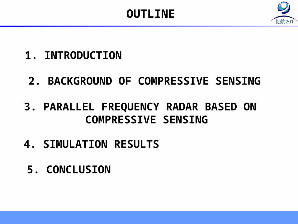
OUTLINE
1. INTRODUCTION
2. BACKGROUND OF COMPRESSIVE SENSING
3. PARALLEL FREQUENCY RADAR BASED ON COMPRESSIVE SENSING
4. SIMULATION RESULTS
5. CONCLUSION
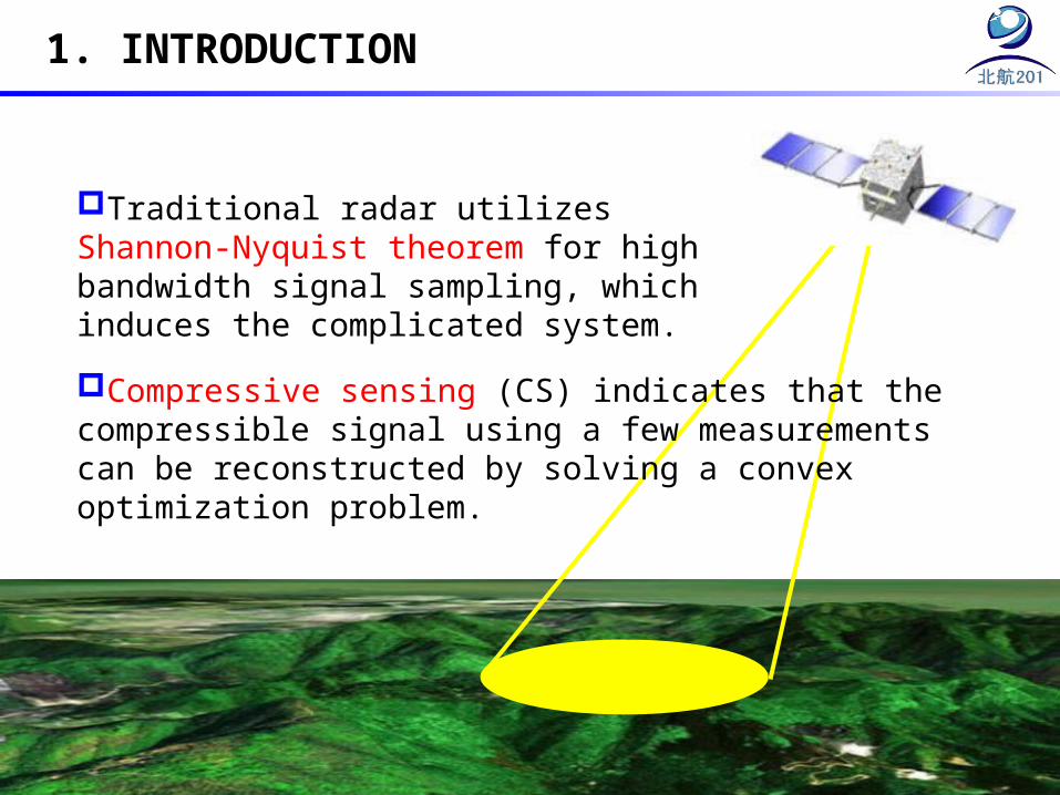
1. INTRODUCTION
Traditional radar utilizes Shannon-Nyquist theorem for high bandwidth signal sampling, which induces the complicated system.
Compressive sensing (CS) indicates that the compressible signal using a few measurements can be reconstructed by solving a convex optimization problem.
1. INTRODUCTION
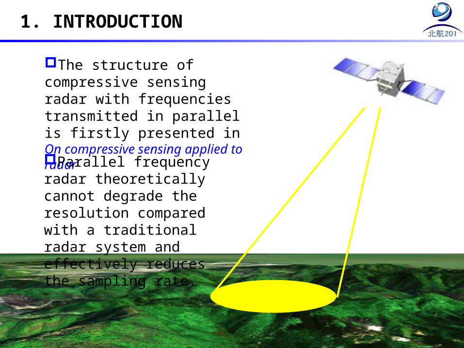
The structure of compressive sensing radar with frequencies transmitted in parallel is firstly presented in On compressive sensing applied to radar
Parallel frequency radar theoretically cannot degrade the resolution compared with a traditional radar system and effectively reduces the sampling rate.

2. BACKGROUND OF COMPRESSIVE SENSING
S x
y S x
1ˆ arg min{ }Nx x x R y x : ,
Basis Pursuit (BP) , Matching Pursuit (MP) and Orthogonal Matching Pursuit (OMP) can solve this convex problem
sparse scene S
convex problem
Sparse scene S can be reconstructed by the above algorithms.
3. PARALLEL FREQUENCY RADAR BASED ON COMPRESSIVE SENSING
3.1 Observation mode
Transmit/Receive antenna
Target
Phase shift echo
Va
f1
f2
fM
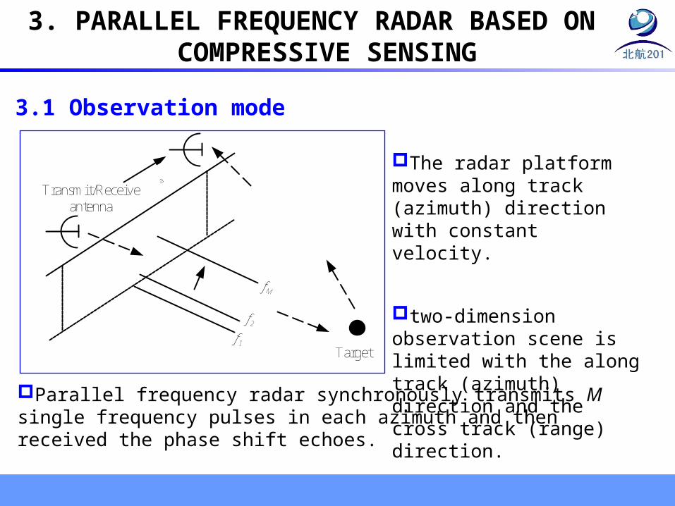
The radar platform moves along track (azimuth) direction with constant velocity.
two-dimension observation scene is limited with the along track (azimuth) direction and the cross track (range) direction.
Parallel frequency radar synchronously transmits M single frequency pulses in each azimuth and then received the phase shift echoes.
Range resolution of traditional pulse compressive radar
Parallel frequency radar synchronously transmits M single frequency pulses in each azimuth with the constant .
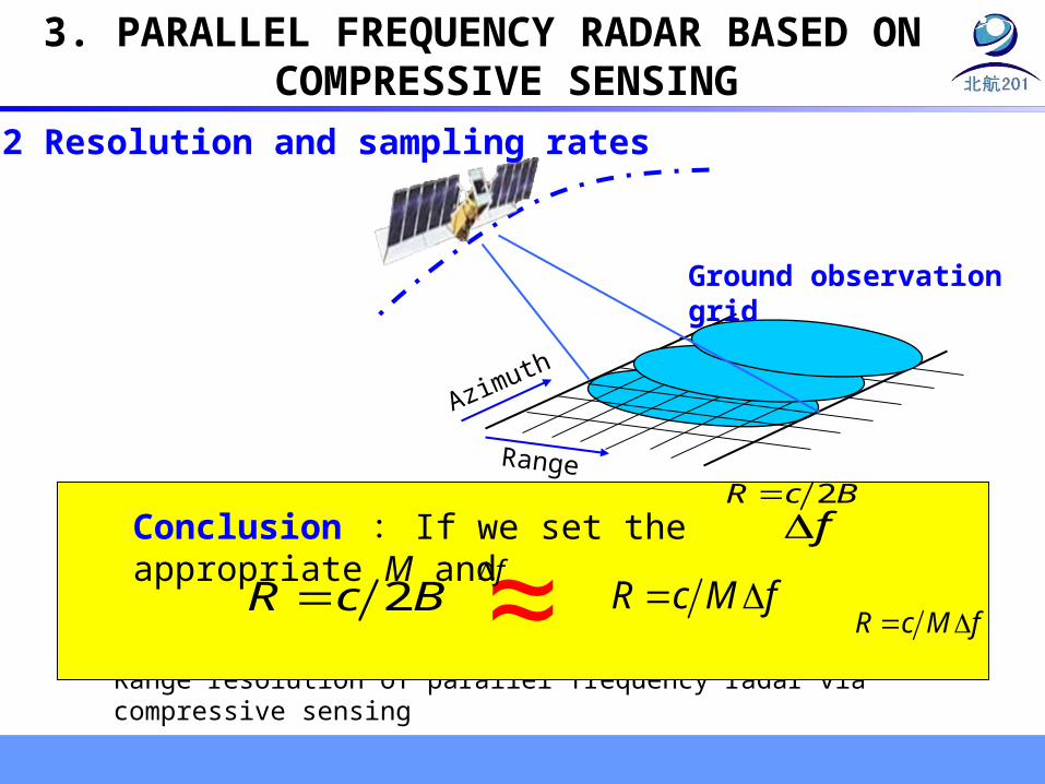
Range resolution of parallel frequency radar via compressive sensing
2R c B
R c M f
fConclusion : If we set the appropriate M and
2R c B R c M f
f
Range
Azimuth
Ground observation grid
3. PARALLEL FREQUENCY RADAR BASED ON COMPRESSIVE SENSING
3.2 Resolution and sampling rates
≈
QDM
High-rate A/D
Transmit/Receiveantenna
Match filter
QM
Chirp signal
f
f0
t
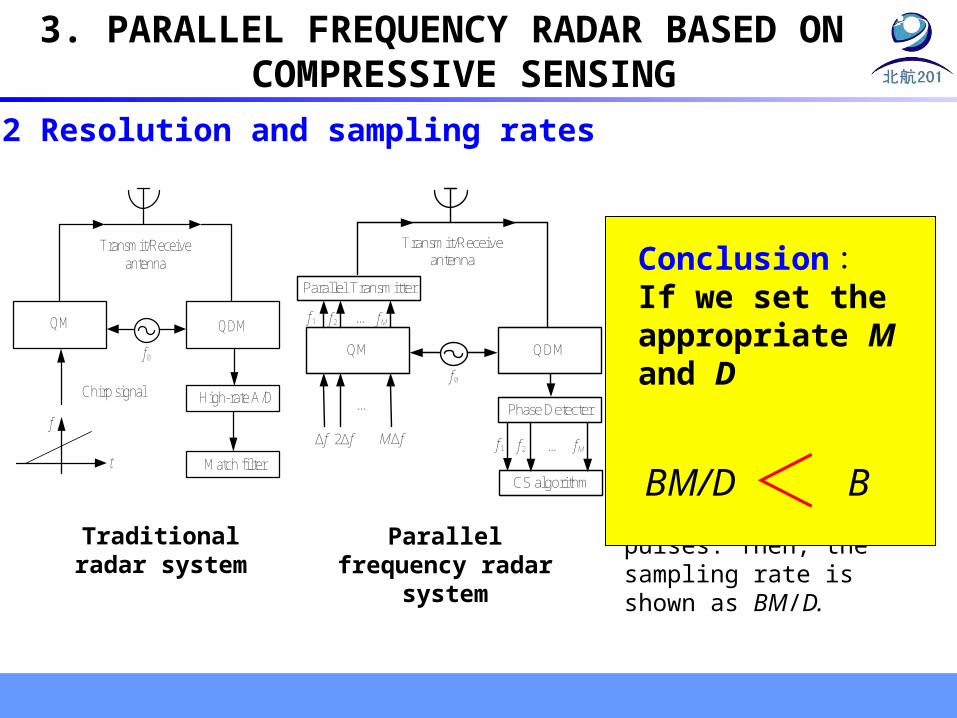
The sampling rate of parellel frequency radar is M/T complex samples per second. Define the time-bandwidth product to be D=BT, B is the total bandwidth of M single frequency pulses. Then, the sampling rate is shown as BM/D.
Conclusion: If we set the appropriate M and D
BBM/DTraditional radar
system
3. PARALLEL FREQUENCY RADAR BASED ON COMPRESSIVE SENSING
QDM
Phase Detecter
Transmit/Receive antenna
Parallel Transmitter
…
CS algorithm
…
QM
Δf
f1 …
2Δf MΔf
f2 fM
f1 f2 fM
f0
Parallel frequency radar system
>3.2 Resolution and sampling rates

The kth echo in a certain azimuth is
The phase information of the target is
The discrete representation is
22 ( )2
( ) ( )k
Ri f t
cRr t Arect t e
c
22 k
Ri f
cky Ae
22
1
nk
RN i fc
k nn
y e x
Y S x x
3. PARALLEL FREQUENCY RADAR BASED ON COMPRESSIVE SENSING
3.3 Imaging based on compressive sensing
The phases of echo signal contain the information of the targets.
Phase demodulation
Azimuth phase compression
Constructing measurement y
OMP recovery
Ka estimating
Constructing measurementmatrix Φ
Raw echo
Image
Y is identity matrix
Ka estimation
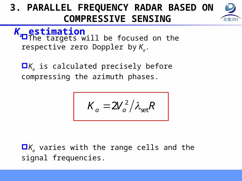
3. PARALLEL FREQUENCY RADAR BASED ON COMPRESSIVE SENSING
The targets will be focused on the respective zero Doppler by Ka.
Ka is calculated precisely before compressing the azimuth
phases.
Ka varies with the range cells and the signal frequencies.
2set2a aK V R

F construction
Prior F
1D observation grid
M single frequency pulses
M echoesphase
detector
M frequencies 1
N
n n
22T
n 1{ }k
n Ri f Mc
ke
Measurement matrix is constructed by prior phase information using discrete grids.
3. PARALLEL FREQUENCY RADAR BASED ON COMPRESSIVE SENSING
3D prior F
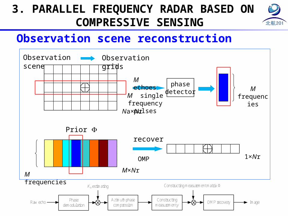
Observation scene Observation grids
Na×Nr
Prior F
M frequenciesM×Nr
M single frequency pulses
M echoesphase
detector M frequencies
recover
OMP 1×Nr
Observation scene reconstruction
3. PARALLEL FREQUENCY RADAR BASED ON COMPRESSIVE SENSING
Raw echo Phase demodulation
Azimuth phase compression
Constructing measurement y
OMP recovery
Ka estimating Constructing measurement matrix Φ
Image

Echo equation 1
Instantaneous range
Approximate representation
Echo equation 2
Demodulating and detecting the phase shift
2 ( )2 ( )2 ( )
( , ) ( ) ( )R
i f tc
a c
Rr t Arect t e
c
2 2 20( ) aR R V
2 22 2 2
0 00
( )2a
a
VR R V R
R
2 2
0
0
22222 ( )
( , ) ( ) ( )aVR ii fi f t Rc
a c
Rr t Arect t e e e
c
2 20
0
22 ( ) 22 2aVRR i fi f i f cRc cy Ae Ae e
Illation
3. PARALLEL FREQUENCY RADAR BASED ON COMPRESSIVE SENSING
0 50 100 150 200 250 300 350 400 450 5000
1
2
3
4
5
6
7
8
9
10
0 50 100 150 200 250 300 350 400 450 5000
1
2
3
4
5
6
7
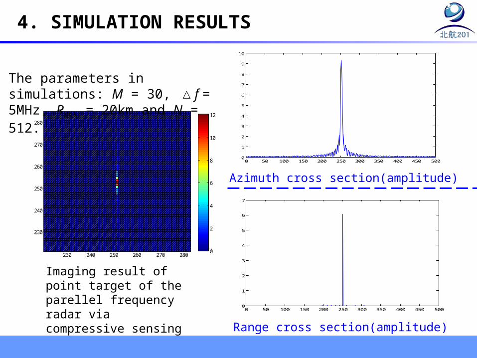
Azimuth cross section(amplitude)
230 240 250 260 270 280
230
240
250
260
270
280
0
2
4
6
8
10
12
Imaging result of point target of the parellel frequency radar via compressive sensing
4. SIMULATION RESULTS
Range cross section(amplitude)
The parameters in simulations: M = 30, △f = 5MHz, RMAX = 20km and N = 512.

230 240 250 260 270 280
230
240
250
260
270
280
0
2
4
6
8
10
12
230 240 250 260 270 280
230
240
250
260
270
280
500
1000
1500
2000
2500
3000
3500
4000
4500
5000
5500
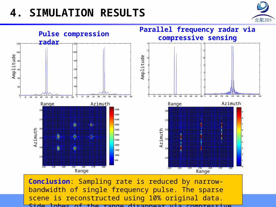
Pulse compression radarParallel frequency radar via
compressive sensing
RD algorithm of pulse compression radar
Compressive sensing algorithm of parallel
frequency radar
4. SIMULATION RESULTS
Imaging results of pulse compression radar and parallel frequency radar via compressive sensing with single or several point targets
230 240 250 260 270 280
230
240
250
260
270
280
脉 冲 压 缩 雷 达
500
1000
1500
2000
2500
3000
3500
4000
4500
5000
230 240 250 260 270 280
230
240
250
260
270
280
M=30基 于 压 缩 感 知 的 平 行 频 率 雷 达
0
2
4
6
8
10
12
距 离 向
方位
向
目 标 图 像
-300 -200 -100 0 100 200 300
-200
-150
-100
-50
0
50
100
150
200
RangeAzimuth
Ran
ge
目 标 图 象
-200 -150 -100 -50 0 50 100 150 200
-150
-100
-50
0
50
100
150
Range
4. SIMULATION RESULTS
Range
Azi
mut
h
200 220 240 260 280 300
200
220
240
260
280
300
Range
Azi
mut
h
200 220 240 260 280 300
200
220
240
260
280
300
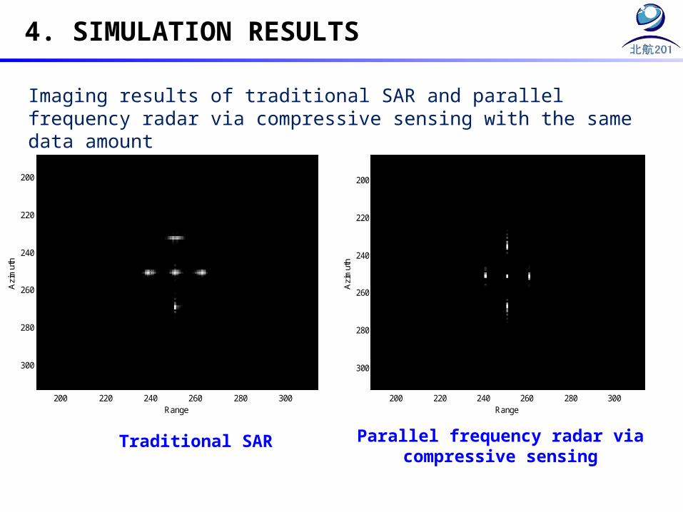
Imaging results of traditional SAR and parallel frequency radar via compressive sensing with the same data amount
Traditional SAR Parallel frequency radar via compressive sensing
220 230 240 250 260 270 280
230
240
250
260
270
280
500
1000
1500
2000
2500
3000
3500
4000
4500
5000
5500
Range
Azi
mut
h
220 230 240 250 260 270 280
230
240
250
260
270
280
0
1
2
3
4
5
6
7
8
9
Range
Azi
mut
h
0 50 100 150 200 250 300 350 400 450 5000
200
400
600
800
1000
1200
Range
Am
plit
ude
0 50 100 150 200 250 300 350 400 450 5000
200
400
600
800
1000
1200
Azimuth
0 50 100 150 200 250 300 350 400 450 5000
2
4
6
8
10
12
14
Am
plit
ude
Range
0 50 100 150 200 250 300 350 400 450 5000
2
4
6
8
10
12
14
Azimuth
4. SIMULATION RESULTS
Pulse compression radarParallel frequency radar via compressive
sensing
Conclusion: Sampling rate is reduced by narrow-bandwidth of single frequency pulse. The sparse scene is reconstructed using 10% original data. Side lobes of the range disappear via compressive sensing.
0 50 100 150 200 250 300 350 400 450 5000
500
1000
1500
2000
2500
3000
0 50 100 150 200 250 300 350 400 450 5000
1
2
3
4
5
6
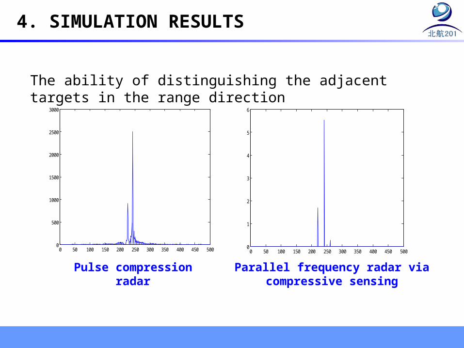
4. SIMULATION RESULTS
The ability of distinguishing the adjacent targets in the range direction
Pulse compression radar Parallel frequency radar via compressive sensing

5. CONCLUSION
This presentation introduces parallel frequency radar and imaging approach based on compressive sensing.
The novel radar can reduce data rate and maintain range resolution with the premise of the appropriate parameters.
The measurement matrix F is composed of the priori phases. The observation scene is reconstructed by OMP.
5. CONCLUSION
The imaging approach based on compressive sensing avoids side lobes of the range.
The noise in received signal is not taken into account in the simulations, it is not ignored in practice.
More researches are required on the capability resisting the noise interference of the signal processing based on compressive sensing in the future.

BEIHANG UNIVERSITY 201 LAB
Thank you for your attention!
IGARSS 2011