Behaviour of Restrained Columns in...
33
Behaviour of Restrained Columns in Fire Y C Wang Manchester Centre for Civil and Construction Engineering
Transcript of Behaviour of Restrained Columns in...
Behaviour of Restrained Columns in Fire
Y C WangManchester Centre for Civil and
Construction Engineering

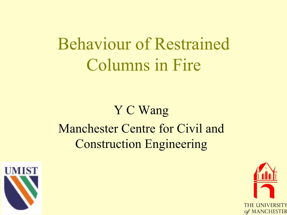
Small Furnace
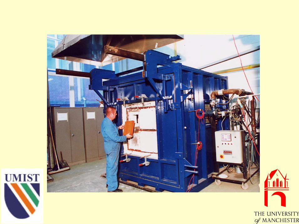
Medium Furnace

Large Furnace
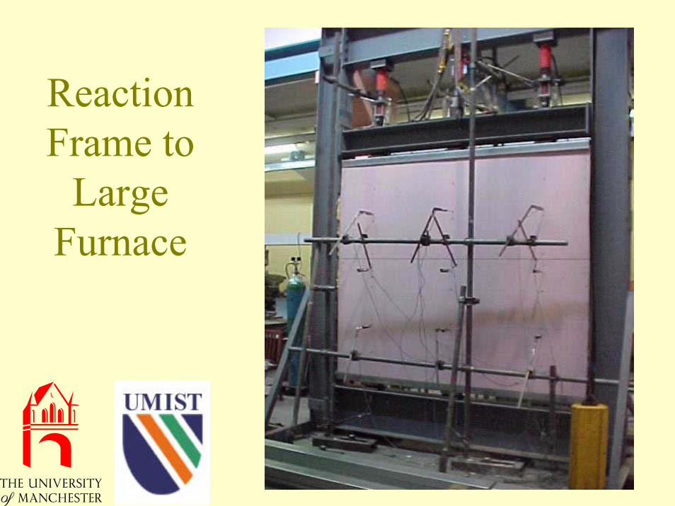
Reaction Frame to
Large Furnace
Objectives
• Bending moment variations in restrained columns in fire
• Effective lengths of restrained columns in fire

Test Programme• 18 restrained steel columns: 9 using fin
plate connections, 9 using extended end plate connections, 3 axial load level, 3 bending moment level
• 16 restrained concrete filled columns: 8 using fin plate connections, 8 using extended end plate connections, two tube sizes, two load levels, balanced and unbalanced beam loads
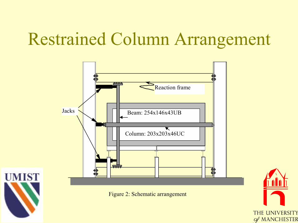
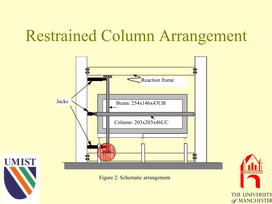
Restrained Column Arrangement
Column: 203x203x46UC
Beam: 254x146x43UBJacks
Reaction frame
Figure 2: Schematic arrangement

Restrained Column Arrangement
Column: 203x203x46UC
Beam: 254x146x43UBJacks
Reaction frame
Figure 2: Schematic arrangement

Column Head Support
Column segmentoutside furnace
JackLoadcell
Reactionframe
Head plate
Roller bar
Loosely fittedbolts inslotted holes
Restrained Column Arrangement
Column: 203x203x46UC
Beam: 254x146x43UBJacks
Reaction frame
Figure 2: Schematic arrangement

Beam End Support
Reactionframe
Restraint beam
Rollerbars

Performance of Sliding Joints -Loading Phase
Figure 3: Comparison between measured column axial load and total applied load at ambient temperature
0
200
400
600
800
1000
1200
0.00 0.20 0.40 0.60 0.80 1.00 1.20 1.40 1.60 1.80
Nominal time
Load
(kN
)
Test SCRII8
Test SCRII5
Total applied load
Measured column axial load

Performance of Sliding Joints -Fire Exposure Phase
Figure 4: Comparison between calculated column axial load and total applied load
0
100
200
300
400
500
600
700
800
900
1000
0 100 200 300 400 500 600 700
Average temperature in column (oC)
Load
(kN
)
Test SCRII8
Test SCRII5
Total applied load
Calculated column axial load from strain gauges on reaction frame

Restrained Column Arrangement
Column: 203x203x46UC
Beam: 254x146x43UBJacks
Reaction frame
Figure 2: Schematic arrangement

Bending Moments in Restrained Steel Columns
Figure 5: Change of bending moments at column head
-40
-30
-20
-10
0
10
20
0 100 200 300 400 500 600 700
Average temperature in column (oC)
Ben
ding
mom
ent (
kN.m
)
Lower beam load = upper beam load
Lower beam load = 0.5*upper beam load

Bending Moment Distribution at Fire Limit State
Initial bendingmoment diagram
Bending momentdiagram in fire

Test Failure Temperatures
400
450
500
550
600
650
700
0 0.1 0.2 0.3 0.4 0.5 0.6 0.7 0.8 0.9 1
Ratio of beam loads
Failu
re te
mpe
ratu
re (o C
)
Test SCRI1
Fin plate connections (series SCRI)
Extended end plate connections (series SCRII)
Load ratio=0.3
Load ratio=0.7
Load ratio=0.5

Effective Lengths of Restrained Steel Columns in Fire
L
x
Le
03.06.00
:,mindet,,,
00
00
22
2
02
2
0
2345
=++⇒=∂∂
=⇒=∂∂
=⇒=+++++=
=
=
=
CBLAL
bygivenlengtheffectiveisLederbetoECBA
D
FFExDxCxBxAx
eeLx
x
e
x
x
x
eχδ
χδ
δδ

Effective Length Ratios
Test numberTest
series 1 2 3 4 5 6 7 8 9
SCRI 0.8 0.775 0.775 0.825 0.664 0.74 0.809 0.78 0.809
SCRII 0.76 0.768 0.751 0.83 0.777 0.761 0.786 0.786 0.766

Comparison between Test Results and BS 5950 Part 8
400
450
500
550
600
650
700
400 450 500 550 600 650 700
Test limiting temperature (oC)
Cal
cula
ted
limiti
ng te
mpe
ratu
re (o C
)
Le=1,with BMLe=1,without BMLe=0.7,with BMLe=0.7,without BMLe=0.84,without BM
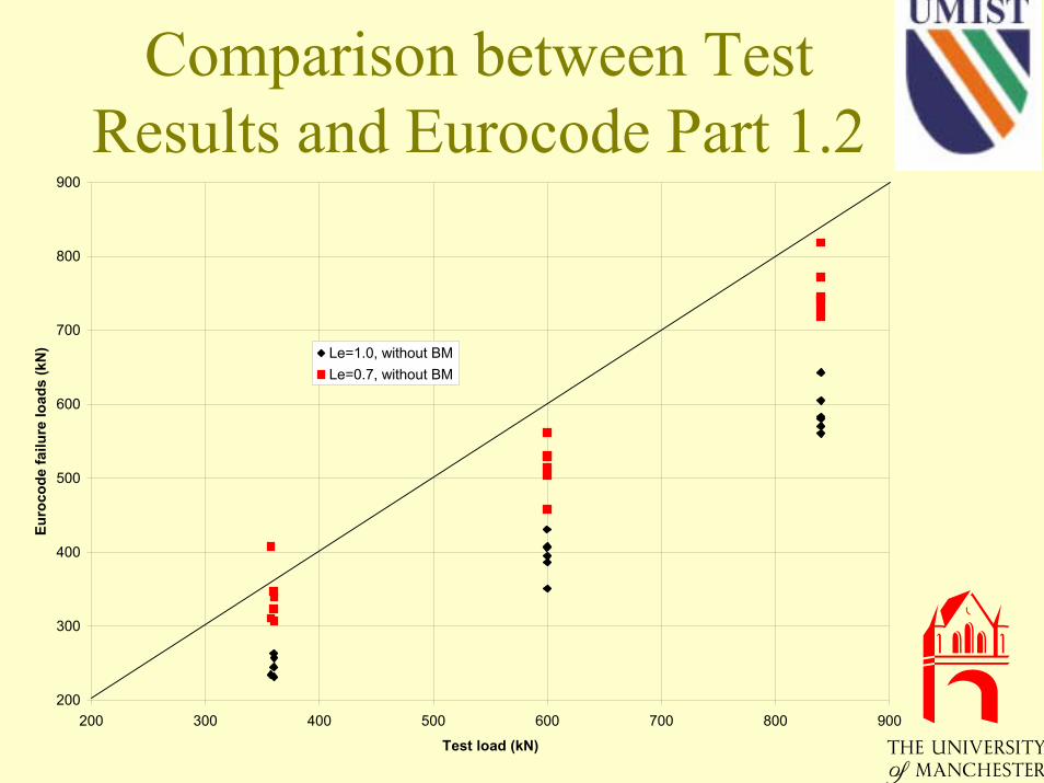
Comparison between Test Results and Eurocode Part 1.2
Fi 21 C i b t t t d E d 3 f il l d
200
300
400
500
600
700
800
900
200 300 400 500 600 700 800 900
Test load (kN)
Euro
code
failu
re lo
ads
(kN
) Le=1.0, without BMLe=0.7, without BM

Effective Length of Restrained Concrete Filled Columns

Fin Plate Connections1600
220
SCR31
870
SCR32
890
SCR33
920
SCR34
900 430
SCR35
1600
200
SCR36
920
SCR37
1560
210
SCR38

Extended End Plate Connections
1630
SCR44
1630
SCR41
940
SCR42
900
SCR43
900
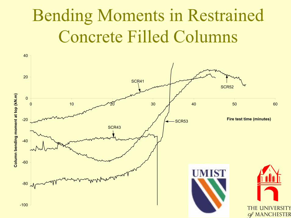
Bending Moments in Restrained Concrete Filled Columns
-100
-80
-60
-40
-20
0
20
40
0 10 20 30 40 50 60
Fire test time (minutes)
Col
umn
bend
ing
mom
ent a
t top
(kN
.m)
SCR53SCR43
SCR41SCR52

Comparison of Results: Fin Plate Connections
0
500
1000
1500
2000
2500
3000
3500
0 500 1000 1500 2000 2500 3000 3500
Test failure time (sec)
Cal
cula
ted
failu
re ti
me
(sec
)
Le=1, with eccentricityLe=1, without eccentricityLe=0.7, with eccentricityLe=0.7, without eccentricity
Le=0.7L
Le=L
SCR38SCR31
SCR36
SCR32
SCR37
SCR33
SCR35
SCR34Arrow indicating conditions to be used in Fire Resistant calculations

Comparison of Results: Extended End Plate Connections
0
500
1000
1500
2000
2500
3000
3500
4000
4500
0 500 1000 1500 2000 2500 3000 3500 4000 4500
Test failure time (seconds)
Cal
cual
ted
failu
re ti
me
(sec
onds
)
SCR44
SCR43
SCR53
SCR54
SCR41SCR52
SCR42
SCR51

Occurrence of Local Buckling
0
10
20
30
40
50
60
70
0 10 20 30 40 50 60
Actual D/t or B/t
Loca
l buc
klin
g lim
it
Composite limit, LBSteel limit, LBComposite limit, NLBSteel limit, NLB

Recommendations for Design
• Bending moments = beam reaction load times eccentricity
• Effective length:(1) Steel columns and concrete filled columns
without local buckling: use Eurocode(2) Concrete filled columns with local
buckling: column height

Acknowledgements
EPSRCCorus