BEHAVIOR OF STEEL PLATE SHEAR WALLS WITH STIFFENED …
19
ASIAN JOURNAL OF CIVIL ENGINEERING (BHRC) VOL. 15, NO. 5 (2014) PAGES 741-759 BEHAVIOR OF STEEL PLATE SHEAR WALLS WITH STIFFENED FULL-HEIGHT RECTANGULAR OPENINGS M.A. Barkhordari 1 , S.A. Asghar Hosseinzadeh 2 M. Seddighi 1 1 Department of Civil Engineering, Iran University of Science and Technology 2 Department of Civil Engineering, Engineering faculty, Golestan University Received: 30 February 2014; Accepted: 5 June 2014 ABSTRACT In the present paper, the behavior of steel plate shear walls (SPSWs) with stiffened full- height rectangular openings is studied. A series of single and multi-story SPSWs of various aspect ratios, with different opening features (i.e. length and horizontal location) and without openings is analyzed using the finite element method to investigate the changes in system behavior due to the introduction of openings in terms of strength, stiffness and ductility. Results show that the opening features can have an important impact on the behavior of SPSWs with the openings. The introduction of stiffened openings always reduces the infill plate strength and also the initial stiffness and ductility, while it somewhat increases the frame strength. It is found that the relative reduction in the infill plate strength as well as the relative reduction in the initial stiffness and ductility due to the introduction of the openings can be reasonably assessed based on the relative reduction in the infill plate area. Keywords: Steel plate shear walls; infill wall; opening; strength; ductility; stiffness. 1. INTRODUCTION In recent years, steel plate shear walls (SPSWs) have been proposed as an effective lateral load resisting system, which resist both wind and earthquake forces. A conventional SPSW system consists of vertical stiffened or unstiffened steel plates surrounded by vertical boundary elements (VBEs), on both sides, and horizontal boundary elements (HBEs), above and below. When properly detailed and designed, both stiffened and unstiffened types are expected to perform satisfactory. However, because of the high cost involved in the fabrication and construction of a stiffened plate as well as the excellent ductility and energy dissipation capacity of unstiffened SPSWs, the unstiffened type is now more popular among researchers and designers. SPSWs have been used successfully in the structural design and retrofitting of a large E-mail address of the corresponding author: [email protected] (M.A. Barkhordari) Archive of SID www.SID.ir
Transcript of BEHAVIOR OF STEEL PLATE SHEAR WALLS WITH STIFFENED …
ASIAN JOURNAL OF CIVIL ENGINEERING (BHRC) VOL. 15, NO. 5 (2014) PAGES 741-759
BEHAVIOR OF STEEL PLATE SHEAR WALLS WITH
STIFFENED FULL-HEIGHT RECTANGULAR OPENINGS
M.A. Barkhordari1, S.A. Asghar Hosseinzadeh2 M. Seddighi1 1Department of Civil Engineering, Iran University of Science and Technology
2Department of Civil Engineering, Engineering faculty, Golestan University
Received: 30 February 2014; Accepted: 5 June 2014
ABSTRACT In the present paper, the behavior of steel plate shear walls (SPSWs) with stiffened full-height rectangular openings is studied. A series of single and multi-story SPSWs of various aspect ratios, with different opening features (i.e. length and horizontal location) and without openings is analyzed using the finite element method to investigate the changes in system behavior due to the introduction of openings in terms of strength, stiffness and ductility. Results show that the opening features can have an important impact on the behavior of SPSWs with the openings. The introduction of stiffened openings always reduces the infill plate strength and also the initial stiffness and ductility, while it somewhat increases the frame strength. It is found that the relative reduction in the infill plate strength as well as the relative reduction in the initial stiffness and ductility due to the introduction of the openings can be reasonably assessed based on the relative reduction in the infill plate area. Keywords: Steel plate shear walls; infill wall; opening; strength; ductility; stiffness.
1. INTRODUCTION
In recent years, steel plate shear walls (SPSWs) have been proposed as an effective lateral load resisting system, which resist both wind and earthquake forces. A conventional SPSW system consists of vertical stiffened or unstiffened steel plates surrounded by vertical boundary elements (VBEs), on both sides, and horizontal boundary elements (HBEs), above and below. When properly detailed and designed, both stiffened and unstiffened types are expected to perform satisfactory. However, because of the high cost involved in the fabrication and construction of a stiffened plate as well as the excellent ductility and energy dissipation capacity of unstiffened SPSWs, the unstiffened type is now more popular among researchers and designers.
SPSWs have been used successfully in the structural design and retrofitting of a large
E-mail address of the corresponding author: [email protected] (M.A. Barkhordari)
Archive
of S
ID
www.SID.ir
M.A. Barkhordari, S.A. Asghar Hosseinzadeh M. Seddighi
742
number of buildings throughout the world [1]. Various experimental and analytical research studies have revealed that this system possesses excellent energy absorption capacity and stable hysteresis characteristics [2-8]. They offer several advantages over the conventional lateral load resisting systems, such as masonry or reinforced concrete shear walls, various types of bracing frames and moment resisting frames. The total weight of a structure and consequently its design seismic forces can be reduced with the use of the SPSW. The highly ductile nature of the SPSW system is another factor that allows for more reduction in the design seismic forces. Further, the SPSW can be constructed with shop welded-field bolted elements, giving much more efficient and faster structural systems. The easiness of openings application in infill plate is another advantage of SPSWs. This system also allows for the passage of different types of openings through the infill plates [2, 9, 10].
Openings are frequently required in SPSWs for passing utilities, architectural purposes and/or structural reasons. Very often, in some SPSW applications, the minimum available plate thickness is much thicker than required by the design and thus, the use of thicker infill plate is inevitable. In turn, the use of larger than required plate thickness increases the tension field forces and consequently the required frame member sizes as per capacity design principles. To alleviate this concern, a regular pattern of circular openings or a single circular opening may be introduced in the infill plate [9, 11]. Besides, window or door-type openings are often required in SPSWs especially where they are used in the building core or in the perimeter frames to provide outside view and light or entrance/exit, respectively [10].
In addition to SPSWs with solid infill plates, research on SPSWs or shear panels with openings has gained some attention in recent years. However, there is still little research available on the topic of SPSWs with window or door-type openings.
Research on circular perforations in shear panels started with Roberts and Sabouri- Ghomi [2]. The researchers performed a series of quasi-static tests under cyclic diagonal loading on unstiffened steel plate shear walls with centrally placed circular openings. Based on the results of this research, they recommended that the ultimate strength and stiffness of a perforated panel could be conservatively approximated by applying a linear reduction factor to the strength and stiffness of a similar solid panel. Deylami and Daftari [12] analyzed more than 50 models with a rectangular opening in the center of the panel using finite element method. The opening had only two stiffeners with limited length on its vertical edges which were not continued across the height of the panel. The researchers concluded that the introduction of the opening, even at relatively small percentage, caused an important reduction of shear capacity. Vian and Bruneau [13] conducted analytical and experimental work on a pattern of multiple regularly spaced circular perforations in the infill plate and a reinforced quarter-circle cut-outs in the upper corners of the infill plate. In addition, Purba and Bruneau [14] performed additional numerical analysis based on the experimental results of the perforated specimens and proposed a more accurate reduction factor than that proposed by Roberts and Sabouri-Ghomi [2] for calculating the strength of a perforated panel.
Valizadeh et al. [15] experimentally investigated cyclic behavior of perforated steel shear panels with circular openings at their center. The results showed that the introduction of openings reduced the initial stiffness and strength and noticeably decreased the energy absorption of the system. Pellegrino et al. [16] studied linear and nonlinear behavior of steel plates with circular and rectangular holes under shear loading. From the results of this research, the strong influence of hole dimensions on the shear buckling coefficient was
Archive
of S
ID
www.SID.ir

BEHAVIOR OF STEEL PLATE SHEAR WALLS WITH STIFFENED FULL-HEIGHT ...
743
observed. Choi and Park [17] conducted experimental and theoretical research on an SPSW system with openings to determine the failure mechanism and proposed a methodology of analysis for lateral resistance capacity of unstiffened SPSWs. The behavior of unstiffened thin SPSWs with circular perforations placed at the center of the infill plates was examined by Bhowmick [11]. Based on the analysis results, a shear strength equation was proposed for SPSWs with circular perforations at the center. On the other hand, Alavi and Nateghi [18] proposed a special combination of diagonal stiffeners with a central circular perforation to enhance the strength, stiffness and energy dissipation capability of perforated SPSWs.
Hosseinzadeh and Tehranizadeh [10] investigated the behavior of SPSWs with large rectangular openings used as windows or doors in buildings. In the case of such large openings, use of horizontal and vertical local boundary elements (LBE) around the opening is inevitable, to offset the effect of the openings on the behavior of the system, as required by current seismic design specifications [1, 19]. However, the involved cost on LBE as well as the increased amount of welding for the connections of the infill plates to the surrounding elements (HBEs, VBEs and LBE) would decrease the economy of the SPSW and thus made the use of such a configuration unattractive or less attractive (see Fig. 1). Anyway, results of this research showed that the behavior of SPSWs with openings and horizontal and vertical LBE was not influenced much by the type (window or door), location and geometry of the openings. Moreover, the introduction of the openings in SPSWs increased both the ultimate strength and stiffness, while it somewhat decreased the ductility ratio.
Figure 1. Partial-height rectangular openings studied by Hosseingzadeh and Tehranizadeh, (a) window-type, and (b) door-type openings, adapted from Ref. [10]
In this paper, the behavior of SPSWs with large rectangular openings used as windows or
doors is studied. To alleviate the concern mentioned above (regarding the additional cost involved), the openings herein are considered to extend the full height of the panel, whether it is needed or not, which results in a similar configuration for both the opening types (window or door). This alternative configuration can be attractive and more economical as it eliminates the need for horizontal LBE at the top and/or bottom of the opening and thus reduces the amount of welding required for infill plate to surrounding member connections. A series of single and multi-story SPSWs of various aspect ratios, with and without the openings is analyzed using the finite element method to examine the changes in the system
Archive
of S
ID
www.SID.ir
M.A. Barkhordari, S.A. Asghar Hosseinzadeh M. Seddighi
744
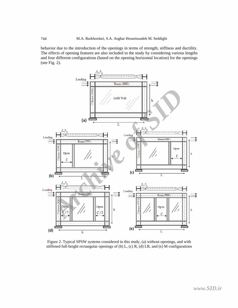
behavior due to the introduction of the openings in terms of strength, stiffness and ductility. The effects of opening features are also included in the study by considering various lengths and four different configurations (based on the opening horizontal location) for the openings (see Fig. 2).
Figure 2. Typical SPSW systems considered in this study, (a) without openings, and with stiffened full-height rectangular openings of (b) L, (c) R, (d) LR, and (e) M configurations
Archive
of S
ID
www.SID.ir

BEHAVIOR OF STEEL PLATE SHEAR WALLS WITH STIFFENED FULL-HEIGHT ...
745
2. METHOD OF THE STUDY 2.1 Design of models A series of single-story and multi-story SPSW systems with different aspect ratios and opening features is considered for this research. The original SPSW models without opening are selected from Ref. [10]. For convenience, the details of the selected SPSW models are presented in Table 1. SPSWs have been designed according to the recommendations given in AISC Seismic Provisions [19] and AISC Design Guide 20 [1]. As shown in Table 1, all models have constant story height of 3.5 m, measured from center to center of HBEs. Bay width (L) of SPSWs, measured from center to center of VBEs, varies from 3 to 7 m (i.e. L/h=0.86, 1.14, 1.43, 1.71 and 2). In addition, all models have had beam-to-column connection details that include reduced beam sections (RBS) at each end, as recommended by AISC Design Guide 20 [1], to ensure inelastic beam action at the desired locations as well as to reduce the bending moment demand on VBEs. Table 2 presents the RBS connection dimensions (see Fig. 2) for different HBE profiles per AISC 358-05 [20].
Table 1: Properties of original SPSWs without the openings, adapted from Ref. [10]
Name # of
stories, n Bay width, L
(m) Aspect
ratio, L/h Plate thickness,
(mm) HBE size
VBE size Intermediate Base & Top
1S3L 1 3 0.86 1st: 3.18 - W14×176 W14×283
1S4L 1 4 1.14 1st: 3.18 - W14×193 W14×311
1S5L 1 5 1.43 1st: 3.18 - W14×233 W14×370
1S6L 1 6 1.71 1st: 3.18 - W24×250 W14×455
1S7L 1 7 2.00 1st: 3.18 - W24×370 W14×550
2S5L 2 5 1.43 1st,2nd: 3.18 W14×132 W14×233 W14×370
3S5L 3 5 1.43 1st~3rd: 3.18 W14×132 W14×233 W14×370
4S5L 4 5 1.43 1st~4th: 3.18 W14×132 W14×233 W14×370
Table 2: RBS connection dimensions for different HBE profiles per AISC 358-05, adapted from Ref. [10]
RBS dimensions W14×132 W14×176 W14×193 W14×233 W24×250 W24×370
a (mm) 200 200 200 220 200 175
b (mm) 300 300 300 330 550 600
c (mm) 90 95 95 100 80 85
The original SPSW models presented in Table 1 are then utilized to study the effects of
various opening features (i.e. opening length and horizontal location) on the system behavior. LBE of SPSWs with openings are designed for stiffness and strength requirements according to the recommendations given in the AISC Design Guide 20 [1]. However, for the opening configuration considered herein, where the LBE span is relatively long, the design of LBE is governed by the stiffness criterion rather than required strength.
Archive
of S
ID
www.SID.ir
M.A. Barkhordari, S.A. Asghar Hosseinzadeh M. Seddighi
746
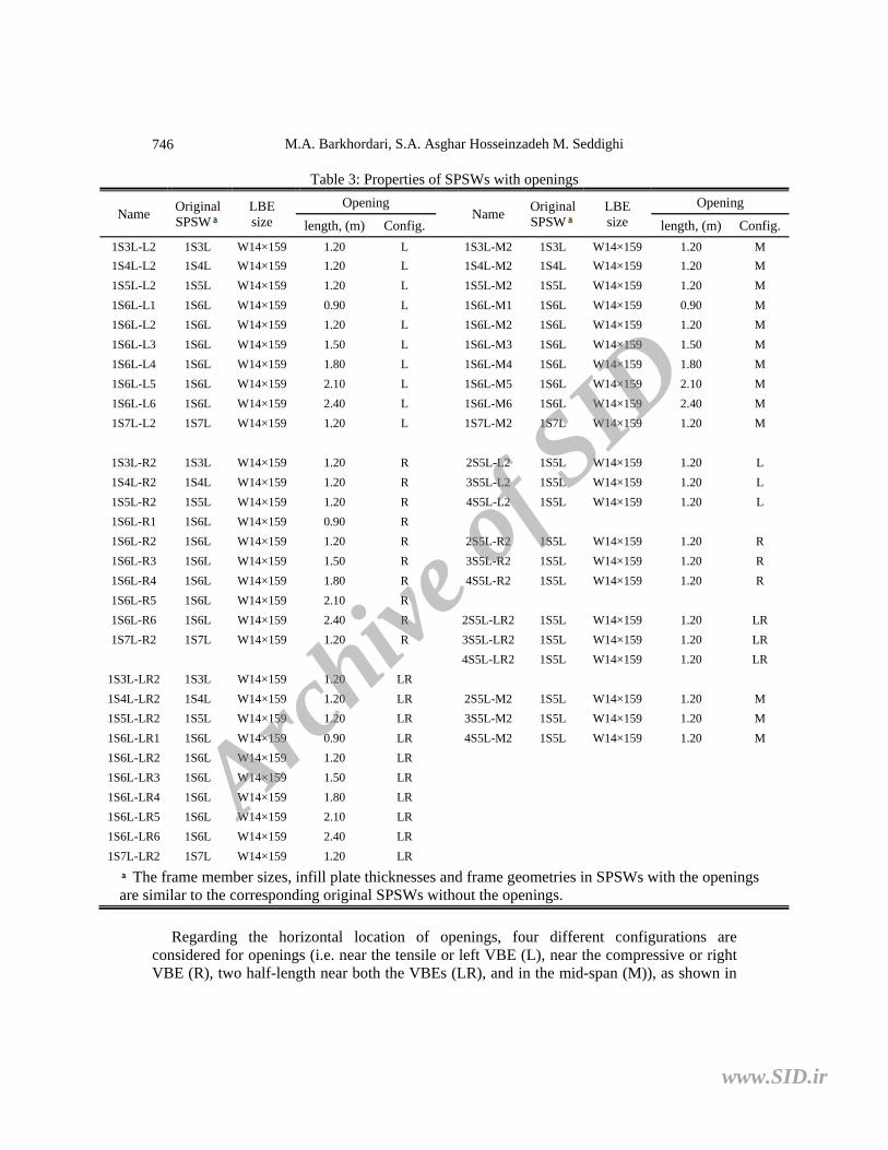
Table 3: Properties of SPSWs with openings
Name Original SPSW
LBE size
Opening Name
Original SPSW
LBE size
Opening
length, (m) Config. length, (m) Config.
1S3L-L2 1S3L W14×159 1.20 L 1S3L-M2 1S3L W14×159 1.20 M
1S4L-L2 1S4L W14×159 1.20 L 1S4L-M2 1S4L W14×159 1.20 M
1S5L-L2 1S5L W14×159 1.20 L 1S5L-M2 1S5L W14×159 1.20 M
1S6L-L1 1S6L W14×159 0.90 L 1S6L-M1 1S6L W14×159 0.90 M
1S6L-L2 1S6L W14×159 1.20 L 1S6L-M2 1S6L W14×159 1.20 M
1S6L-L3 1S6L W14×159 1.50 L 1S6L-M3 1S6L W14×159 1.50 M
1S6L-L4 1S6L W14×159 1.80 L 1S6L-M4 1S6L W14×159 1.80 M
1S6L-L5 1S6L W14×159 2.10 L 1S6L-M5 1S6L W14×159 2.10 M
1S6L-L6 1S6L W14×159 2.40 L 1S6L-M6 1S6L W14×159 2.40 M
1S7L-L2 1S7L W14×159 1.20 L 1S7L-M2 1S7L W14×159 1.20 M
1S3L-R2 1S3L W14×159 1.20 R 2S5L-L2 1S5L W14×159 1.20 L
1S4L-R2 1S4L W14×159 1.20 R 3S5L-L2 1S5L W14×159 1.20 L
1S5L-R2 1S5L W14×159 1.20 R 4S5L-L2 1S5L W14×159 1.20 L
1S6L-R1 1S6L W14×159 0.90 R
1S6L-R2 1S6L W14×159 1.20 R 2S5L-R2 1S5L W14×159 1.20 R
1S6L-R3 1S6L W14×159 1.50 R 3S5L-R2 1S5L W14×159 1.20 R
1S6L-R4 1S6L W14×159 1.80 R 4S5L-R2 1S5L W14×159 1.20 R
1S6L-R5 1S6L W14×159 2.10 R
1S6L-R6 1S6L W14×159 2.40 R 2S5L-LR2 1S5L W14×159 1.20 LR
1S7L-R2 1S7L W14×159 1.20 R 3S5L-LR2 1S5L W14×159 1.20 LR
4S5L-LR2 1S5L W14×159 1.20 LR
1S3L-LR2 1S3L W14×159 1.20 LR
1S4L-LR2 1S4L W14×159 1.20 LR 2S5L-M2 1S5L W14×159 1.20 M
1S5L-LR2 1S5L W14×159 1.20 LR 3S5L-M2 1S5L W14×159 1.20 M
1S6L-LR1 1S6L W14×159 0.90 LR 4S5L-M2 1S5L W14×159 1.20 M
1S6L-LR2 1S6L W14×159 1.20 LR
1S6L-LR3 1S6L W14×159 1.50 LR
1S6L-LR4 1S6L W14×159 1.80 LR
1S6L-LR5 1S6L W14×159 2.10 LR
1S6L-LR6 1S6L W14×159 2.40 LR
1S7L-LR2 1S7L W14×159 1.20 LR
The frame member sizes, infill plate thicknesses and frame geometries in SPSWs with the openings are similar to the corresponding original SPSWs without the openings.
Regarding the horizontal location of openings, four different configurations are
considered for openings (i.e. near the tensile or left VBE (L), near the compressive or right VBE (R), two half-length near both the VBEs (LR), and in the mid-span (M)), as shown in
Archive
of S
ID
www.SID.ir

BEHAVIOR OF STEEL PLATE SHEAR WALLS WITH STIFFENED FULL-HEIGHT ...
747
Fig. 2. The length of openings is assumed to vary between L' = 0.9 m to L' = 2.4 m, while, as mentioned before, the height of openings is fixed equal to the clear distance between HBEs (i.e. full-height openings). The details of different SPSW models with openings are presented in Table 3.
2.2 Description of finite element models The ASTM A36 and ASTM A572 Gr.50 standards are respectively selected for infill plate and frame member (VBEs, HBEs and LBE) materials. The respective stress-strain relationships of the two materials are shown in Fig. 3. According to the figures, different yield strengths are assumed for infill plate (=327.6 MPa) and frame member (=385 MPa) materials, while the elastic modulus (=200 GPa) and Poisson’s ratio (=0.3) are considered the same for both the materials.
Fig. 3. Material stress-strain curves, (a) Infill plates, and (b) Frame members, adapted from Ref. [21]
The finite element modeling approach used in the previous works by the author [10, 22]
is utilized to model and analyze SPSWs using the finite element program ABAQUS/Standard [23]. A description of the finite element modeling is presented in the following.
All frame members and infill plates are modeled with a reasonably fine mesh using S4R element. The S4R element is a four node reduced integration quadrilateral shell element and is capable of modeling elastic, plastic and large-strain behaviors. An isotropic hardening model is used for all nonlinear pushover analyses. The geometric nonlinearity phenomenon is included in the analyses as a consequence of large displacements with small strains.
The infill plates are assumed to be connected directly to the surrounding boundary members. To simulate the fix support conditions at the VBE bases, the bottom nodes of both VBE flanges and webs are restrained from displacement in all directions. To replicate the effects of the concrete slab of the floors, all HBE webs are also restrained against movement in the out-of-plane direction.
Initial imperfections in the infill plates of SPSWs due to gravity, fabrication tolerances and welding distortion are inevitable. Such imperfections need to be considered in finite element models, somehow, to help initiate buckling in the infill plate and development of the tension fields. To consider this effect, the infill plate is taken to have an initial imperfection pattern corresponding to the first buckling mode of the plate with a peak amplitude of 1mm. Lateral loads, as shown in Fig. 2, are equally applied to the beam-to-
Archive
of S
ID
www.SID.ir

M.A. Barkhordari, S.A. Asghar Hosseinzadeh M. Seddighi
748
column connections at each story level and are gradually increased from zero to a magnitude beyond the system’s capacity. The ultimate state of SPSWs is considered to occur as the drift ratio at least at one of the stories of the systems reaches a value of 2.5% per [24].
The FE modeling approach described above has previously been validated [10, 22] by comparing the analysis results of the four story SPSW tested by [6] and the single-story SPSW (only SPSW2 specimen) tested by [8] with the corresponding experimental results and good agreement between analytical and experimental results was observed. Thus, it is not repeated here for brevity.
3. DISCUSSION OF RESULTS
As expected, the behavior of a SPSW before and after the introduction of full-height opening and vertical LBE would not be the same. The introduction of the opening reduces the infill plate total area and consequently the infill plate stiffness and strength. On the other side, the introduction of the vertical LBE on the opening side(s) would increase the stiffness and strength of the moment frame. In fact, the vertical LBE acting as struts for HBEs stiffen the frame, to some extent, in addition to primarily permitting the infill plates to yield in tension.
Herein, the effect of the introduction of full-height openings on the behavior of SPSWs is discussed. First, the changes in the system behavior due to the introduction of the openings in terms of strength, initial stiffness and ductility are investigated for openings of various lengths and four different configurations. Then, the influence of the system aspect ratio on the variations of the system strength, initial stiffness and ductility is examined for typical single-story SPSWs having different opening configurations but equal opening length. Finally, the influence of the system height (i.e. number of story) on the behavior of the system is studied for typical single and multi-story SPSWs having different opening configurations but equal opening length.
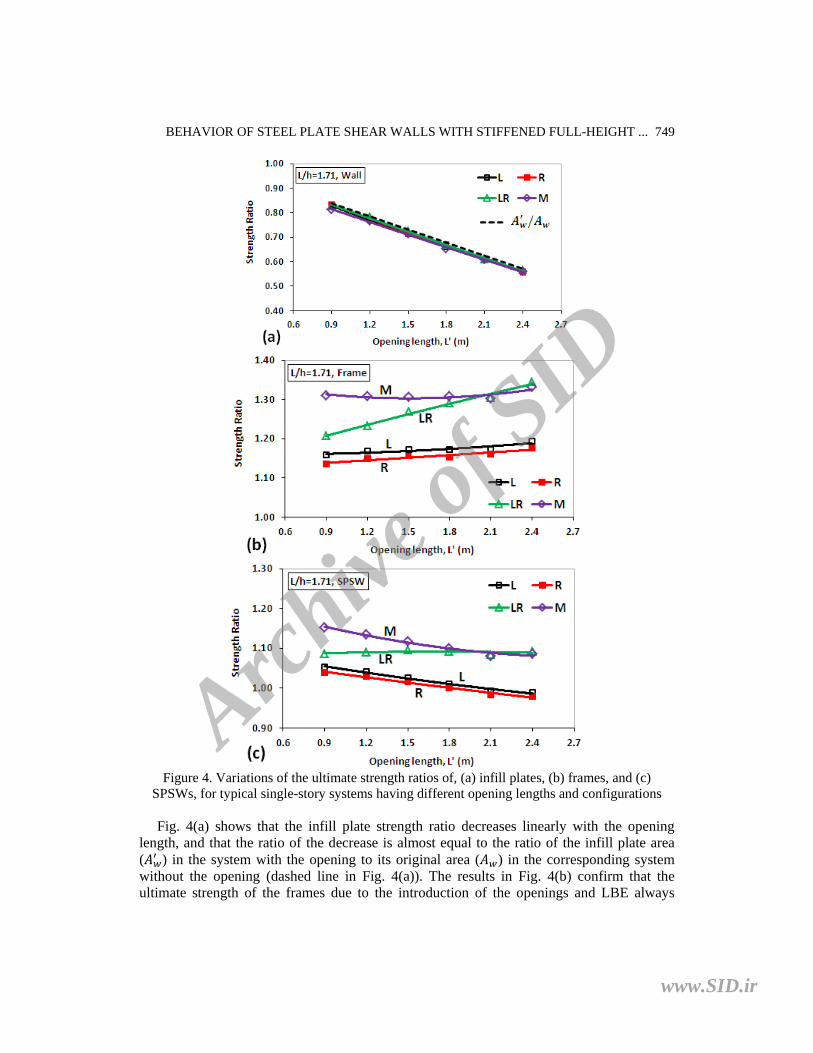
3.1 Effects of the opening length and configuration In this section, the effects of the opening length and configuration on the system strength, initial stiffness and ductility are investigated for typical single-story SPSWs of an aspect ratio of 1.71, with different opening lengths (L = 0.9, 1.2, 1.5, 1.8, 2.1 and 2.4 m) and configurations (L, R, LR and M) and without the openings. 3.1.1 Ultimate strength Fig. 4 compares the variations of the ultimate strength ratios of typical single-story SPSWs with the openings to the corresponding SPSW without the opening for four different opening configurations and various opening lengths. As shown, for comparison purposes, the variations of the ultimate strength ratios of infill plates and frames are also presented in Fig. 4. The ultimate strength of the infill plate is calculated by means of integrating shear stresses across the width of the infill plate, and that of the frame is determined by subtracting that of the infill plate from the overall strength.
Archive
of S
ID
www.SID.ir
BEHAVIOR OF STEEL PLATE SHEAR WALLS WITH STIFFENED FULL-HEIGHT ...
749
Figure 4. Variations of the ultimate strength ratios of, (a) infill plates, (b) frames, and (c)
SPSWs, for typical single-story systems having different opening lengths and configurations
Fig. 4(a) shows that the infill plate strength ratio decreases linearly with the opening length, and that the ratio of the decrease is almost equal to the ratio of the infill plate area ( ) in the system with the opening to its original area ( ) in the corresponding system without the opening (dashed line in Fig. 4(a)). The results in Fig. 4(b) confirm that the ultimate strength of the frames due to the introduction of the openings and LBE always
Archive
of S
ID
www.SID.ir
M.A. Barkhordari, S.A. Asghar Hosseinzadeh M. Seddighi
750
increases. In addition, the ratio of the increase in the frame strength is greater for LR and M configurations that have two vertical LBE on the opening sides than for L and R configurations that have one vertical LBE on the opening side, as expected. The results in Fig. 4(b) also indicate that the ratio of the increase in the frame strength is almost constant for L, R and M configurations for the range of the opening length considered (L'=0.9-2.4 m), while it is linearly increased for LR configuration with increasing the opening length. As a result, as observed in Fig. 4(c), the ultimate strength of the SPSWs with the openings may be higher or smaller than that of the corresponding SPSW without the opening depending on the opening length and configuration. Fig. 4(c) illustrates that for L, R and M configurations, the SPSW strength ratio decreases with increasing the opening length, whereas for M configuration, it remains almost constant for the different opening lengths considered (i.e. L'=0.9-2.4 m). It is also noted from the results in Fig. 4(c) that the introduction of the opening and LBE in the mid-span (M configuration) provides a relatively higher additional strength to the system; however, this configuration also involves a higher additional cost compared to L and R configurations.
Moreover, the comparison of the results in Fig. 4(a)-(c) shows that there is no considerable difference between the curves for L and R configurations. This indicates that the behavior of a single-story SPSW having a stiffened full-height opening on the left (or right) side of the panel would remain symmetric for the lateral loads applied in both directions.
Notably, the results in this section, unlike the ones presented in Ref. [10] for the partial-height openings that require the use of both horizontal and vertical LBE around the openings, demonstrate that the behavior of a SPSW with full-height opening, depending on the opening length and location, can be different.
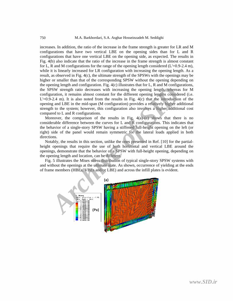
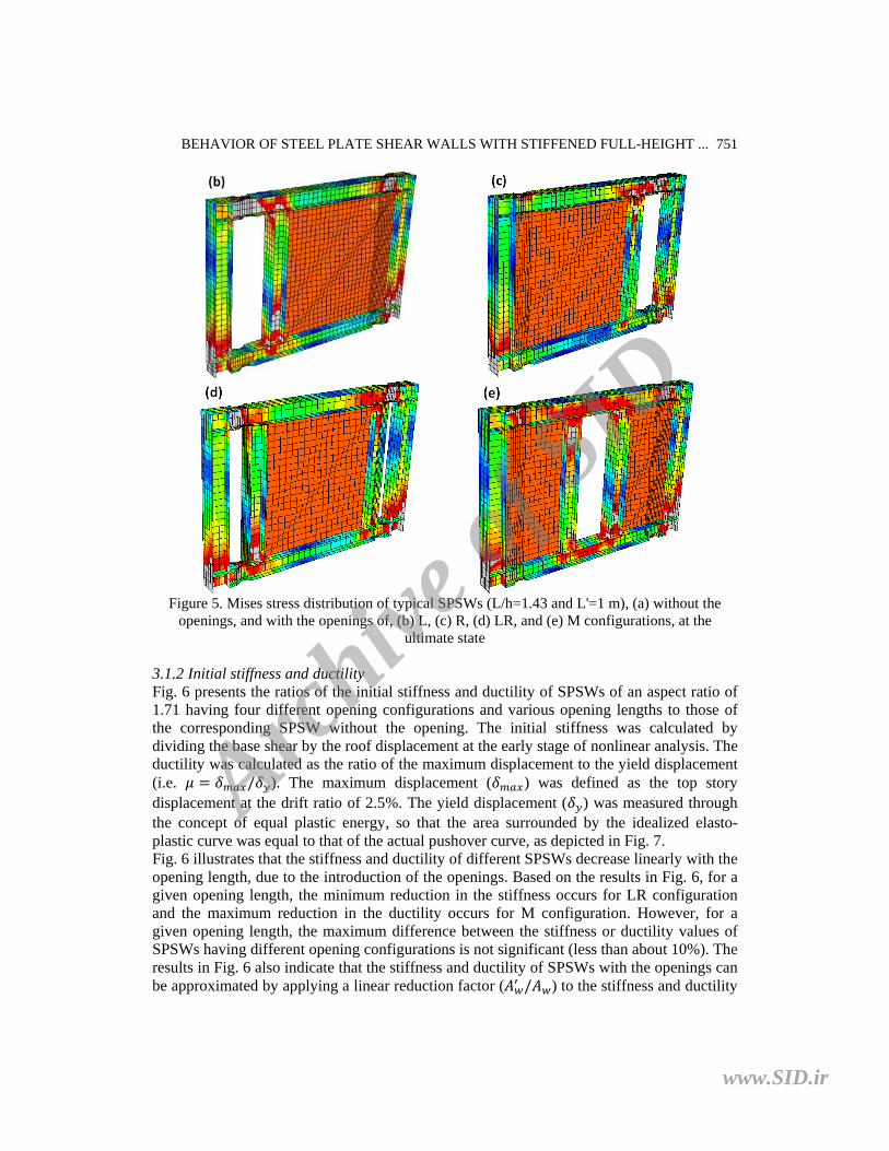
Fig. 5 illustrates the Mises stress distribution of typical single-story SPSW systems with and without the openings at the ultimate state. As shown, occurrence of yielding at the ends of frame members (HBEs, VBEs and/or LBE) and across the infill plates is evident.
Archive
of S
ID
www.SID.ir
BEHAVIOR OF STEEL PLATE SHEAR WALLS WITH STIFFENED FULL-HEIGHT ...
751
Figure 5. Mises stress distribution of typical SPSWs (L/h=1.43 and L'=1 m), (a) without the
openings, and with the openings of, (b) L, (c) R, (d) LR, and (e) M configurations, at the ultimate state
3.1.2 Initial stiffness and ductility Fig. 6 presents the ratios of the initial stiffness and ductility of SPSWs of an aspect ratio of 1.71 having four different opening configurations and various opening lengths to those of the corresponding SPSW without the opening. The initial stiffness was calculated by dividing the base shear by the roof displacement at the early stage of nonlinear analysis. The ductility was calculated as the ratio of the maximum displacement to the yield displacement (i.e. / ). The maximum displacement ( ) was defined as the top story displacement at the drift ratio of 2.5%. The yield displacement ( ) was measured through the concept of equal plastic energy, so that the area surrounded by the idealized elasto-plastic curve was equal to that of the actual pushover curve, as depicted in Fig. 7. Fig. 6 illustrates that the stiffness and ductility of different SPSWs decrease linearly with the opening length, due to the introduction of the openings. Based on the results in Fig. 6, for a given opening length, the minimum reduction in the stiffness occurs for LR configuration and the maximum reduction in the ductility occurs for M configuration. However, for a given opening length, the maximum difference between the stiffness or ductility values of SPSWs having different opening configurations is not significant (less than about 10%). The results in Fig. 6 also indicate that the stiffness and ductility of SPSWs with the openings can be approximated by applying a linear reduction factor ( / ) to the stiffness and ductility
Archive
of S
ID
www.SID.ir

M.A. Barkhordari, S.A. Asghar Hosseinzadeh M. Seddighi
752
of the corresponding SPSW without the opening; however, it should be noted that this approximation may be somewhat conservative or unconservative (less than 15%) depending on the opening length and configuration.
Figure 6. Variations of the, (a) initial stiffness, and (b) ductility, ratios of typical single-story
SPSWs (L/h=1.71) for different opening lengths and configurations
Figure 7. Definition of a yield point, adapted from Ref. [10]
Archive
of S
ID
www.SID.ir

BEHAVIOR OF STEEL PLATE SHEAR WALLS WITH STIFFENED FULL-HEIGHT ...
753
3.2 Effect of the SPSW aspect ratio The results in the previous section have been presented for single-story SPSWs of equal aspect ratio (i.e. L/h=1.71). In this section, to examine the influence of the system aspect ratio on the strength, initial stiffness and ductility ratios of SPSWs with the openings to the corresponding systems without the openings, typical single-story SPSWs of various aspect ratios (L/h = 0.86, 1.14, 1.43, 1.71 and 2) having four different opening configurations (L, R, LR and M) but equal opening length (L'=1.2 m) are considered. 3.2.1 Ultimate strength Fig. 8 presents the ultimate strength ratios of SPSWs with the openings to the corresponding SPSW without the opening for different aspect ratios. Fig. 8(a) shows that generally, the infill plate strength ratio increases with the increase of the system aspect ratio. This can be explained by the fact that for a given opening length, with the increase of the system aspect ratio, the relative reduction in the infill plate area and therefore the effect of the introduction of the opening on the infill plate strength decrease. The results in Fig. 8(a) also confirm that the infill plate strength ratio, independent of the system aspect ratio and the opening configuration, is almost equal to the ratio of the infill plate area ( ) in the system with the opening to its original area ( ) in the corresponding system without the opening (dashed line in Fig. 8(a)). From the results in Fig. 8(b), again, it is observed that the ultimate strength of the frames due to the introduction of the LBE always increases, and that for a given aspect ratio, the ratio of the increase is somewhat greater for SL and M configurations that have two vertical LBE in the span than for L and R configurations that have one vertical LBE in the span. Based on the results in Fig. 8(b), the frame strength ratios vary between 1.19 and 1.41 for SL and M configurations, and between 1.09 and 1.24 for L and R configurations, for different aspect ratios. The maximum difference between LR and M configuration curves as well as the maximum difference between L and R configuration curves is less than 8%. These observations indicate that both the number and position of the LBE in the span are important factors in increasing the frame strength. As a result, as shown in Fig. 8(c), the SPSW strengths increase up to 4% due to the introduction of the openings of L or R configurations, and up to 16% due to the introduction of the openings of LR or M configurations, for different aspect ratios.
Archive
of S
ID
www.SID.ir

M.A. Barkhordari, S.A. Asghar Hosseinzadeh M. Seddighi
754
Figure 8. Variations of the ultimate strength ratios of, (a) infill plates, (b) frames, and (c)
SPSWs, for typical single-story systems having different aspect ratios and opening configurations
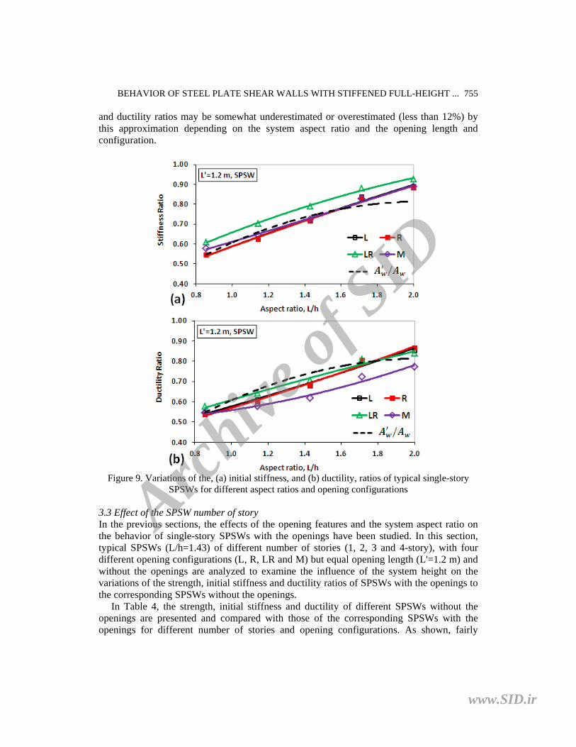
3.2.2 Initial stiffness and ductility Fig. 9 presents the initial stiffness and ductility ratios of SPSWs with the openings to the corresponding SPSW without the opening for different aspect ratios. Fig. 9 shows that due to the reduction in the infill plate area, the initial stiffness and ductility are lower for SPSWs with the openings than for the corresponding SPSW without the opening. The results in Fig. 9 illustrate that both the stiffness and ductility ratios increase almost linearly with the system aspect ratio. This can be explained by the fact that for a given opening length, the relative reduction in the infill plate area decreases with the increase of the system aspect ratio and therefore, the contribution of the infill plate tension field action to the overall behavior increases; with this effect, the stiffness and ductility of SPSWs with the openings increase with the aspect ratio. Based on the results in Fig. 9, again, it is shown that both the initial stiffness and ductility ratios can be approximated by the ratio of the infill plate area ( ) in the system with the opening to its original area ( ) in the corresponding system without the opening (dashed lines in Fig. 9(a) and (b)). However, as shown in Fig. 9, the initial stiffness
Archive
of S
ID
www.SID.ir
BEHAVIOR OF STEEL PLATE SHEAR WALLS WITH STIFFENED FULL-HEIGHT ...
755
and ductility ratios may be somewhat underestimated or overestimated (less than 12%) by this approximation depending on the system aspect ratio and the opening length and configuration.
Figure 9. Variations of the, (a) initial stiffness, and (b) ductility, ratios of typical single-story
SPSWs for different aspect ratios and opening configurations
3.3 Effect of the SPSW number of story In the previous sections, the effects of the opening features and the system aspect ratio on the behavior of single-story SPSWs with the openings have been studied. In this section, typical SPSWs (L/h=1.43) of different number of stories (1, 2, 3 and 4-story), with four different opening configurations (L, R, LR and M) but equal opening length (L'=1.2 m) and without the openings are analyzed to examine the influence of the system height on the variations of the strength, initial stiffness and ductility ratios of SPSWs with the openings to the corresponding SPSWs without the openings.
In Table 4, the strength, initial stiffness and ductility of different SPSWs without the openings are presented and compared with those of the corresponding SPSWs with the openings for different number of stories and opening configurations. As shown, fairly
Archive
of S
ID
www.SID.ir

M.A. Barkhordari, S.A. Asghar Hosseinzadeh M. Seddighi
756
similar results are obtained for different opening configurations. The results in Table 4 show that the infill plate strength ratio does not change with the height of the system and therefore, regardless of the system height, it can be determined by the relative reduction in the infill plate area (or the ratio of ⁄ ). The results in Table 4 for the frame strength ratio show that generally, with the increase of the height of the system, the effect of the introduction of the opening and LBE on the frame strength decreases. As a result, the overall strength ratio decreases with the increase of the height of the system. On average, the ultimate strength ratio of SPSWs decreases from 1.23 for the shortest SPSW to 1.11 for the tallest SPSW for L and R opening configurations, while it decreases from 1.38 for the shortest SPSW to 1.17 for the tallest SPSW for LR and M opening configurations.
Table 4: Comparison of the strength, stiffness and ductility of SPSWs (L/h=1.71) with the
openings (L'=1.2 m) with those of the corresponding SPSWs without the openings for different number of stories and opening configurations
SPSWs without the openings
SPSWs with the openings Ratios (with openings / without openings)
Name Strength (kN) Stiffness
(kN/mm) Ductility Name
Strength Stiffness Ductility
SPSW Infill Frame SPSW Infill Frame 1S5L 6885 2505 4380 465.4 7.0 1S5L-L2 1.05 0.73 1.24 0.72 0.682S5L 6602 2501 4100 271.0 7.9 2S5L-L2 0.97 0.72 1.13 0.63 0.65 3S5L 6185 2509 3676 178.0 7.0 3S5L-L2 0.94 0.72 1.10 0.61 0.66 4S5L 5617 2519 3098 122.1 5.8 4S5L-L2 0.94 0.71 1.12 0.62 0.69
1S5L-R2 1.04 0.72 1.22 0.72 0.68 2S5L-R2 0.96 0.72 1.11 0.63 0.64 3S5L-R2 0.94 0.72 1.09 0.61 0.66 4S5L-R2 0.93 0.71 1.10 0.62 0.68 1S5L-LR2 1.12 0.72 1.35 0.79 0.71 2S5L-LR2 1.04 0.72 1.24 0.72 0.68 3S5L-LR2 0.99 0.71 1.19 0.71 0.74 4S5L-LR2 0.97 0.71 1.18 0.72 0.78 1S5L-M2 1.15 0.72 1.41 0.72 0.62 2S5L-M2 1.05 0.72 1.25 0.63 0.59 3S5L-M2 0.99 0.72 1.17 0.60 0.62 4S5L-M2 0.97 0.72 1.16 0.60 0.65
The results in Table 4 also indicate that as in the case of the infill plate strength ratio, the
ductility and stiffness ratios do not change significantly with the height of the system. Thus, as in the case of single-story SPSWs, the stiffness and ductility ratios of multi-story SPSWs can be approximated by the ratio of ⁄ .
4. CONCLUSIONS
A series of single and multi-story (up to 4-story) SPSWs of different aspect ratios (L/h =
Archive
of S
ID
www.SID.ir

BEHAVIOR OF STEEL PLATE SHEAR WALLS WITH STIFFENED FULL-HEIGHT ...
757
0.86, 1.14, 1.43, 1.71 and 2) with and without stiffened rectangular openings used as windows or doors in buildings was numerically analyzed to study the effects of such openings on the behavior of the systems. The openings herein were assumed to extend the full height of the systems (so as to reduce the additional cost involved on LBE and the amount of welding required for infill plate-to-LBE connections), and to have various lengths (L'=0.9, 1.2, 1.5, 1.8, 2.1 and 2.4 m) and four different configurations (based on the horizontal location of the opening). The results showed that:
- Unlike the results in the previous work [10] for the partial-height openings that require the use of both horizontal and vertical LBE, the behavior of SPSWs with stiffened full-height openings is affected by the location and length of such openings. This confirms that the behavior of a SPSW with the opening, depending on the opening type (partial-height or full-height opening), can be different.
- The introduction of stiffened full-height openings in different SPSWs reduces the ultimate strength of infill plates, while it increases the ultimate strength of frames. Regardless of the system geometries and the opening length and configuration, the ratio of the reduction in the infill plate strength is almost equal to the relative reduction in the infill plate area (i.e. ⁄ ). The ratio of the increase in the frame strength is dependent on the system geometries as well as the opening length and configuration (number and position of LBE in the span). As a result, the ultimate strength of SPSWs due to the introduction of stiffened openings may be increased or decreased.
- Generally, for a given opening configuration, the SPSW strength ratio decreases with increasing the system height and/or the opening length. Also, the SPSW strength ratio is greater for LR and M configurations that require the use of two vertical LBE than for L and R configurations that require the use of only one vertical LBE.
- The initial stiffness and ductility values of SPSWs due to the introduction of stiffened opening are always decreases. Based on the results obtained, the stiffness and ductility values of SPSWs are almost proportional to the infill plate area. Thus, the stiffness and ductility ratios of SPSWs with the openings to the corresponding SPSWs without the openings can be approximated by the ratio of ⁄ .
- No difference is observed between the behaviors of SPSWs with the openings of L and R configurations. This indicates that the behavior of a SPSW with a stiffened full-height opening on the left (or right) side of the panel would remain symmetric for the lateral loads applied in both directions.
- Based on the results obtained, it can be inferred that by increasing the infill plate thickness in proportion to the decrease of the infill plate area, the strength, initial stiffness and possibly ductility of SPSWs with the openings would be achieved close to the corresponding SPSWs without the openings (this needs further investigation).
REFERENCES
1. AISC. Steel design guide 20, steel plate shear walls. Chicago (IL): American Institute of Steel Construction, 2007.
2. Roberts TM, Sabouri-Ghomi S. Hysteretic characteristics of unstiffened perforated steel plate shear panels, Thin-Walled Structures, 14(1992) 139-51.
Archive
of S
ID
www.SID.ir

M.A. Barkhordari, S.A. Asghar Hosseinzadeh M. Seddighi
758
3. Elgaaly M, Caccese V, Du C. Postbuckling behavior of steel-plate shear walls under cyclic loads, Journal of Structural Engineering, ASCE, 119(1993) 588-605.
4. Nakashima M, Iwai S, Iwata M, Takeuchi T, Konomi S, Akazawa T, Sabouri K. Energy dissipation behaviour of shear panels made of low yield steel, Earthquake Engineering & Structural Dynamics, 23(1994) 1299-313.
5. Nakashima M. Strain-hardening behaviour of shear panel made of low yield steel. I: test, Journal of Structural Engineering, ASCE, 121(1995) 1742-9.
6. Driver RG, Kulak GL, Kennedy DJL, Elwi AE. Cyclic test of four-story steel plate shear wall, Journal of Structural Engineering, ASCE, 124(1998) 112-30.
7. Rezai M. Seismic Behaviour of Steel Plate Shear Walls by Shake Table Testing, PhD Dissertation, Department of Civil Engineering, University of British Columbia, Vancouver, BC, 1999.
8. Lubell AM, Prion HGL, Ventura CE, Rezai M. Unstiffened steel plate shear performance under cyclic loading, Journal of Structural Engineering, ASCE, 126(2000) 454–60.
9. Vian D, Bruneau M, Tsai KC, Lin YC. Special perforated steel plate shear walls with reduced beam section anchor beams I: experimental investigation, Journal of Structural Engineering, 135(2009) 211-20.
10. Hosseinzadeh SAA, Tehranizadeh M. Introduction of stiffened large rectangular openings in steel plate shear walls, Journal of Constructional Steel Research, 77(2012) 180-92.
11. Bhowmick AK. Seismic behavior of steel plate shear walls with centrally placed circular perforations, Thin-Walled Structures, 75(2014) 30-42.
12. Deylami A, Daftari H. Non-linear behavior of steel shear wall with large rectangular opening, Proceeding on CD-Rom. 12th World Conference on Earthquake Engineering, New Zealand, 2000, [Paper No.408].
13. Vian D, Bruneau M. Steel Plate Shear Walls for Seismic Design and Retrofit of Building Structures, Technical Report No. MCEER-05-0010, Multidisciplinary center for earthquake engineering research, State University of New York at Buffalo, Buffalo, N.Y., 2005.
14. Purba R, Bruneau M. Finite-element investigation and design recommendations for perforated steel plate shear walls, Journal of Structural Engineering, ASCE, 135(2009) 1367–76.
15. Valizadeh H, Sheidaii M, Showkati H. Experimental investigation on cyclic behavior of perforated steel plate shear walls, Journal of Constructional Steel Research, 70(2012) 308–16.
16. Pellegrino C, Maiorana E, Modena C. Linear and non-linear behaviour of steel plates with circular and rectangular holes under shear loading, Thin-Walled Structures, 47(2009) 607–16.
17. Choi I, Park H. Steel plate shear walls with various infill plate designs, Journal of Structural Engineering, ASCE, 135(2009) 785–96.
18. Alavi E, Nateghi F. Experimental study on diagonally stiffened steel plate shear walls with central perforation, Journal of Constructional Steel Research, 89(2013) 9–20.
19. AISC, ANSI/AISC 341-05. Seismic Provisions for Structural Steel Buildings, Chicago (IL): American Institute of Steel Construction, 2005.
Archive
of S
ID
www.SID.ir
BEHAVIOR OF STEEL PLATE SHEAR WALLS WITH STIFFENED FULL-HEIGHT ...
759
20. AISC, ANSI/AISC 358-05. Prequalified Connections for Special and Intermediate Steel Moment Frames For Seismic Applications, Chicago (IL): American Institute of Steel Construction, 2005.
21. Habashi HR, Alinia MM. Characteristics of the wall–frame interaction in steel plate shear walls, Journal of Constructional Steel Research, 66(2010) 150–8.
22. Hosseinzadeh SAA, Tehranizadeh M. The wall–frame interaction effect in steel plate shear wall systems. Journal of Constructional Steel Research, 98(2014) 88-99.
23. ABAQUS/Standard Theory Manual, Version 6.5.1. Hibbitt, Karlsson, Sorenson, Inc, (HKS), 2004.
24. ASCE, SEI/ASCE 7-05. Minimum Design Loads for Buildings and Other Structures, Virginia (USA): American Society of Civil Engineers, 2005.
Archive
of S
ID
www.SID.ir