
Behavior of Multi-pile Foundation for Offshore Wind Generator
16
Wenjun LU, Ga Zhang Behavior of Multi - pile Foundation for Offshore Wind Generator State Key Laboratory of Hydroscience and Engineering, Tsinghua University, P R China
Transcript of Behavior of Multi-pile Foundation for Offshore Wind Generator

Wenjun LU, Ga Zhang
Behavior of Multi-pile Foundation
for Offshore Wind Generator
State Key Laboratory of Hydroscience and Engineering, Tsinghua University, P R China

CONTENTS
State Key Laboratory of Hydroscience and Engineering, Tsinghua University, P R China
1
Method
Numerical Simulation
Load Bearing Mechanism
Background
2
3
4

目录
Offshore wind power attracted increasing attention
One of the key technology of offshore wind generator is foundations
The most widely used type is pile foundation
1
Monopile Tripod Jacket Group-pile
Multiple-pile
Background
State Key Laboratory of Hydroscience and Engineering, Tsinghua University, P R China
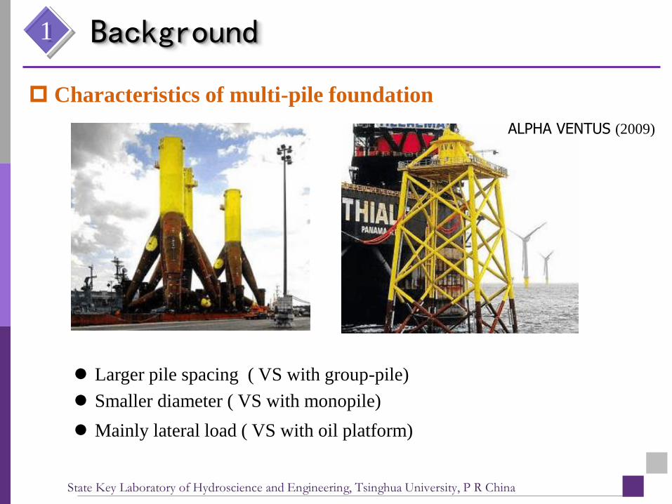
Characteristics of multi-pile foundation
Larger pile spacing ( VS with group-pile)
Smaller diameter ( VS with monopile)
Mainly lateral load ( VS with oil platform)
ALPHA VENTUS (2009)
1 Background
State Key Laboratory of Hydroscience and Engineering, Tsinghua University, P R China

目录2 Method
Test method
Numericalmodel
Study of soil-pile systerm
Centrifuge model test
Numerical analysis
validate Application
State Key Laboratory of Hydroscience and Engineering, Tsinghua University, P R China

目录3 Numerical Simulation
Mohr-Coulomb yielding criterion
densityPosson's
ratio
Young's
modulus
friction
anglecohesion
soil 17.6 kN/m3 0.4 4 MPa 30 º 5 KPa
pile 25 kN/m3 0.3 20 GPa - -
steel 78.5 kN/m3 0.25 210 GPa - -
Soil: ideal elastic-plastic model
Pore pressure degree of freedom
Upper structure: linear elastic model
Pile: linear elastic model
State Key Laboratory of Hydroscience and Engineering, Tsinghua University, P R China

目录3
Simulation of a monopile test
Numerical Simulation
Load-displacement relationshipMoment along the pile
State Key Laboratory of Hydroscience and Engineering, Tsinghua University, P R China

目录3
Simulation of a five-pile test
Load-displacement relationship
State Key Laboratory of Hydroscience and Engineering, Tsinghua University, P R China
Numerical Simulation

目录3
P1’
P2’
t
t
P1’ P2’ M’ V’
8 MNA=0.2 MN
f=1.8 HZ100 MNm 3.40 MN
Application
State Key Laboratory of Hydroscience and Engineering, Tsinghua University, P R China
Numerical Simulation

Laterl displacement at the last moment
3
Application
State Key Laboratory of Hydroscience and Engineering, Tsinghua University, P R China
Numerical Simulation

Plastic zone
3
Application
State Key Laboratory of Hydroscience and Engineering, Tsinghua University, P R China
Numerical Simulation

目录4 Load Bearing Mechanism
M
V
H
Individual effectBearing the load by the pile itself
General effectTensioning or compressing in the axial direction
State Key Laboratory of Hydroscience and Engineering, Tsinghua University, P R China

目录
Axial Load Ratio —— Va /V0
V0 Va
4 Load Bearing Mechanism
State Key Laboratory of Hydroscience and Engineering, Tsinghua University, P R China

目录
Axial load ratio of pile2 and pile4 V0
Va
V0
Va
目录4 Load Bearing Mechanism
Axial Load Ratio —— Va /V0
Va
/ V
0
State Key Laboratory of Hydroscience and Engineering, Tsinghua University, P R China

目录
monopile Pile2 Pile3 Pile4
Axial force (MN) -3.4 -11.31 -3.78 8.72
Shear force (MN) 8 1.19 1.17 2.13
Moment (MNm) 100 8.02 9.40 7.98
2.5
29.4
0.11
0.71
0.10
2.49
0.25
0.74
Traditional p-y curve is no longer suitable.
Axial force
Lateral force
Coupling effect of axial and lateral force should be taken into account.
4 Load Bearing Mechanism
State Key Laboratory of Hydroscience and Engineering, Tsinghua University, P R China

Thanks!
State Key Laboratory of Hydroscience and Engineering, Tsinghua University, P R China


![[P. Le Tirant] Design Guides for Offshore Structures Offshore Pile Design](https://static.fdocuments.us/doc/165x107/563dbb49550346aa9aabde71/p-le-tirant-design-guides-for-offshore-structures-offshore-pile-design.jpg)


