Behavior of large piled-raft foundation on clay...
12
Behavior of large piled-raft foundation on clay soil Shivanand Mali * , Baleshwar Singh Department of Civil Engineering, Indian Institute of Technology Guwahati, Guwahati 781039, Assam, India ARTICLE INFO Keywords: Piled-raft Numerical modeling Clay soil Settlement ratio Bending moment ratio Shear force ratio Raft-soil stiffness ratio ABSTRACT The piled-raft foundation is usually adopted to support the offshore structures. In the present study, a large piled- raft has been simulated numerically through 3-D finite element modeling. The objective of the present study was to investigate the effect of pile spacing, pile length, pile diameter and raft-soil stiffness ratio on the settlement, load-sharing, bending moments, and shear force behavior of large piled-raft foundation. The results indicated that with increase in pile spacing up to the 5 to 6 times of the pile diameter, both average settlement ratio and dif- ferential settlement ratio decreased effectively and thereafter it increased gradually. Raft with smaller raft-soil stiffness ratio and larger pile group to raft width ratio observed to be effective in decreasing the average set- tlement ratio. The load-sharing ratio decreased with increase in pile spacing whereas; it increased with increase in pile length. With increase in pile spacing, bending moment ratio increased and as the length of pile increased bending moment ratio decreased up to pile group to raft width ratio of 0.6 and thereafter it increased. 1. Introduction The piled-raft is a geotechnical foundation consisting of the three el- ements raft, piles and soil. Burland (1977) proposed that the piles can be used to reduce the settlement of the raft foundation. In piled-raft foun- dation, the total load of the superstructure is partly carried by the piles and the raft. The distribution of total load among the piles, raft and soil depends on their relative stiffnesses. Based on the dimensions of the raft and piles, the piled-raft has been classified as a small piled-raft (B r /L p < 1) and large piled-raft (B r /L p > 1) (Viggiani, 2001; Sanctis and Mandolini, 2006; Mandolini et al., 2013). In a small piled-raft, the flexural stiffness of the raft is usually high and the differential settlement does not represent a problem. Here, the primary reason to add the piles is to achieve a suffi- cient factor of safety against the bearing failure. However, in a large piled-raft, piles are added essentially to reduce the settlement. Poulos (2001) indicated that the 3-D numerical modeling is the most reliable method for the analysis of the piled-raft foundation in a clay soils. The maximum settlement, differential settlement, raft bending moments and shear force, axial loads and pile bending moments are considered as crucial parameter for optimum design of piled-raft foun- dation. Several researchers have been investigated the settlement (Pra- koso and Kulhawy, 2001; Cho et al., 2012; Sinha and Hanna, 2016) and bearing behavior (Reul, 2004; Sanctis and Mandolini, 2006; Lee et al., 2010) of a piled-raft foundation on clay soils by numerical modeling. Oh et al. (2008) conducted a study on the piled-raft foundation in sandy soil by numerical modeling. They reported that with increase in raft thickness and pile spacing, the bending moment of the piled-raft increased. The different design aspects of the piled-raft foundation have been reported by Seo et al. (2003), and Reul and Randolph (2004). Ghalesari et al. (2015) suggested that the piled-raft foundation can be adopted as offshore foundation to reduce the settlement and to enhance the bearing capacity of the foundation. Furthermore, Poulos and Devdas (2005), Poulos and Bunce (2008), Poulos et al. (2011), Rabiei and Choobbasti (2016) indicated that the piled-raft can be used as an effec- tive and economic foundation alternative for tall buildings to control the settlement and to enhance the bearing capacities. In addition to this, Nguyen et al. (2014) conducted a parametric study of large piled-raft foundations in sandy soil through finite element modeling. They indicated that the concentrated pile arrangement method can help to considerably reduce the settlements and bending moments of the raft. However, very few parametric studies by means of numerical modeling have been reported for the large piled-raft foundation on a clay soils. Therefore, the effect of different parameters on large piled-raft foundation needs to be investigated. The intended large piled-raft foundation can be used for the construction of residential or commercial buildings situated near onshore line where mostly undrained conditions prevail. 1.1. Objective and scope of the study In a large piled-raft foundation, the width of raft is relatively larger in * Corresponding author. E-mail addresses: [email protected] (S. Mali), [email protected] (B. Singh). Contents lists available at ScienceDirect Ocean Engineering journal homepage: www.elsevier.com/locate/oceaneng https://doi.org/10.1016/j.oceaneng.2017.12.029 Received 6 July 2017; Received in revised form 12 October 2017; Accepted 10 December 2017 Available online 27 December 2017 0029-8018/© 2017 Published by Elsevier Ltd. Ocean Engineering 149 (2018) 205–216
Transcript of Behavior of large piled-raft foundation on clay...

Ocean Engineering 149 (2018) 205–216
Contents lists available at ScienceDirect
Ocean Engineering
journal homepage: www.elsevier.com/locate/oceaneng
Behavior of large piled-raft foundation on clay soil
Shivanand Mali *, Baleshwar Singh
Department of Civil Engineering, Indian Institute of Technology Guwahati, Guwahati 781039, Assam, India
A R T I C L E I N F O
Keywords:Piled-raftNumerical modelingClay soilSettlement ratioBending moment ratioShear force ratioRaft-soil stiffness ratio
* Corresponding author.E-mail addresses: [email protected] (S. Ma
https://doi.org/10.1016/j.oceaneng.2017.12.029Received 6 July 2017; Received in revised form 12 OctobAvailable online 27 December 20170029-8018/© 2017 Published by Elsevier Ltd.
A B S T R A C T
The piled-raft foundation is usually adopted to support the offshore structures. In the present study, a large piled-raft has been simulated numerically through 3-D finite element modeling. The objective of the present study wasto investigate the effect of pile spacing, pile length, pile diameter and raft-soil stiffness ratio on the settlement,load-sharing, bending moments, and shear force behavior of large piled-raft foundation. The results indicated thatwith increase in pile spacing up to the 5 to 6 times of the pile diameter, both average settlement ratio and dif-ferential settlement ratio decreased effectively and thereafter it increased gradually. Raft with smaller raft-soilstiffness ratio and larger pile group to raft width ratio observed to be effective in decreasing the average set-tlement ratio. The load-sharing ratio decreased with increase in pile spacing whereas; it increased with increase inpile length. With increase in pile spacing, bending moment ratio increased and as the length of pile increasedbending moment ratio decreased up to pile group to raft width ratio of 0.6 and thereafter it increased.
1. Introduction
The piled-raft is a geotechnical foundation consisting of the three el-ements raft, piles and soil. Burland (1977) proposed that the piles can beused to reduce the settlement of the raft foundation. In piled-raft foun-dation, the total load of the superstructure is partly carried by the pilesand the raft. The distribution of total load among the piles, raft and soildepends on their relative stiffnesses. Based on the dimensions of the raftand piles, the piled-raft has been classified as a small piled-raft (Br/Lp< 1)and large piled-raft (Br/Lp > 1) (Viggiani, 2001; Sanctis and Mandolini,2006; Mandolini et al., 2013). In a small piled-raft, the flexural stiffness ofthe raft is usually high and the differential settlement does not represent aproblem. Here, the primary reason to add the piles is to achieve a suffi-cient factor of safety against the bearing failure. However, in a largepiled-raft, piles are added essentially to reduce the settlement.
Poulos (2001) indicated that the 3-D numerical modeling is the mostreliable method for the analysis of the piled-raft foundation in a claysoils. The maximum settlement, differential settlement, raft bendingmoments and shear force, axial loads and pile bending moments areconsidered as crucial parameter for optimum design of piled-raft foun-dation. Several researchers have been investigated the settlement (Pra-koso and Kulhawy, 2001; Cho et al., 2012; Sinha and Hanna, 2016) andbearing behavior (Reul, 2004; Sanctis and Mandolini, 2006; Lee et al.,2010) of a piled-raft foundation on clay soils by numerical modeling.
Oh et al. (2008) conducted a study on the piled-raft foundation in
li), [email protected] (B. Singh
er 2017; Accepted 10 December 201
sandy soil by numerical modeling. They reported that with increase inraft thickness and pile spacing, the bending moment of the piled-raftincreased. The different design aspects of the piled-raft foundationhave been reported by Seo et al. (2003), and Reul and Randolph (2004).Ghalesari et al. (2015) suggested that the piled-raft foundation can beadopted as offshore foundation to reduce the settlement and to enhancethe bearing capacity of the foundation. Furthermore, Poulos and Devdas(2005), Poulos and Bunce (2008), Poulos et al. (2011), Rabiei andChoobbasti (2016) indicated that the piled-raft can be used as an effec-tive and economic foundation alternative for tall buildings to control thesettlement and to enhance the bearing capacities.
In addition to this, Nguyen et al. (2014) conducted a parametric study oflarge piled-raft foundations in sandy soil through finite element modeling.They indicated that the concentrated pile arrangement method can help toconsiderably reduce the settlements and bending moments of the raft.However, very few parametric studies by means of numerical modelinghave been reported for the large piled-raft foundation on a clay soils.Therefore, the effect of different parameters on large piled-raft foundationneeds to be investigated. The intended large piled-raft foundation can beused for the construction of residential or commercial buildings situatednear onshore line where mostly undrained conditions prevail.
1.1. Objective and scope of the study
In a large piled-raft foundation, the width of raft is relatively larger in
).
7

S. Mali, B. Singh Ocean Engineering 149 (2018) 205–216
comparison with the length of piles and the piles are added primarily toreduce the settlements. Thus, the present paper aims to analyze the set-tlement, load-sharing, bending moment and shear force behavior of largepiled-raft foundation subjected to vertical load on a clay soil. In order tounderstand these behaviors, the influence of various parameters such aspile spacing (Sp), pile length (Lp), pile diameter (dp) and raft-soil stiffnessratio (Krs) was studied through PLAXIS 3D software. A series of numericalsimulations for different piled-raft configurations was performed to fulfillthe aim of the present study. Based on the parametric study, theapproximate design steps and concluded observations are summarized.
2. Finite element modeling
2.1. Finite element mesh and boundary conditions
The model consisted of the soil mass with unaffected boundary con-ditions, foundation geometry with square raft of 45 m width (Br), inter-face element and the applied uniformly distributed load (q) of 200 kPa.Fig. 1 shows the typical finite element mesh, plan view of quarter piled-raft and 10-node tetrahedral soil element with 3-node embedded beamelement. The water table was considered at ground level. From the edgeof the raft, lateral soil domain boundaries of the model were placed at adistance of twice the width of raft and restrained against horizontaltranslation but with vertical translation of soil being allowed. Fig. 2shows the cross sectional view of piled-raft foundation. The bottom soilboundary was at a vertical distance of a twice the width of raft plus two-third the length of pile and was restricted from both horizontal andvertical translations (Gandhi and Maharaj, 1995).
Globally fine mesh has been selected for the entire soil domain andrelatively very fine mesh was chosen in the vicinity of the structural
Fig. 1. (a) Typical finite element mesh used in the parametric study, (b) Plan view (quarter of
206
elements. The very fine meshing has been generated with coarsenessfactor of 0.25 i.e. the size of element in very fine meshing is 0.25 timesthat of size of element in fine meshing. The analysis of piled-raft involvedtwo stages, namely initial stage and loading stage. In the initial stage, thesoil domain was activated and in the loading stage, the piled-raft ge-ometry and applied load were activated and run was made. As reportedby Shrestha et al. (2017), in the present study undrained soil responsewas modeled for the precise modeling of onshore piled-raft foundations.From the preliminary analysis of the piled-raft under the applied loading,it was found that the selected lateral boundaries of the soil domain weresufficient because the observed zone of plastic strain developed in the soilwas equal to width of raft (Br) laterally from the edge of the raft.
2.2. Constitutive modeling
Mohr-Coulomb model require lesser number of input parameter ofsoil. Therefore, in present study the soil was modeled as 10-node tetra-hedral elements with the elastic-perfectly plastic Mohr-Coulomb model.The parameters required for modeling consisted of cohesion, angle ofinternal friction, Young's modulus and Poisson's ratio. As per the Mohr-Coulomb failure criteria, the yielding or failure takes place in the soilmass as the mobilized shear stress at any plane becomes equal to theshear strength of soil. To simplify the analysis process, the constantvalues of the material parameters were used for entire soil domain(Ranjan and Rao, 2007).
The raft and piles were modeled as 5-node triangular plate elementsand 4-node line elements, respectively. The raft and piles remains inelastic state as their modulus of elasticity is greater than the soil; there-fore, the material of raft and piles were considered to be linear-elastically. The piles and raft were connected by rigid connection.
the piled-raft) and, (c) 10-node tetrahedral element with 3-node embedded beam element.

Fig. 2. Cross section of piled-raft foundation (For Bg/Br ¼ 0.6, Sp ¼ 4.6 m).
S. Mali, B. Singh Ocean Engineering 149 (2018) 205–216
Moreover, the raft-soil interface was considered as a smooth contact withstrength reduction factor (Rinter) of 0.67. The Rinter indicates the strengthof interface element as a percentage of the shear strength of adjacent soiland is indicated by the Eqns. (1) and (2).
ci ¼ Rinter � csoil (1)
tan∅i ¼ Rinter � tan∅soil (2)
where ci is the interface cohesion, φi is the interface friction angle, csoil isthe surrounding soil cohesion, and φsoil is the surrounding soil frictionangle.
Fig. 3 shows the pile-soil interface technique used in the present study(Jeong et al., 2004). Fig. 3(a) and (b) show the “no slip” and “slip”conditions between the soil and pile elements, respectively. The inter-action between the soil and the pile was modeled by the embeddedinterface elements of 3-node line elements with pairs of nodes instead ofsingle nodes. One node of each pair belongs to the beam element,whereas other node is point in the 10-node wedge element belonging tosoil element.
Fig. 3. Pile-soil interface modeling technique (a) no slip, (b)
207
In the finite element formulation, the coordinates of each node pairare identical, which indicates that the interface element has a zerothickness (h ¼ 0) (Fig. 3(a)). Interface elements follow the Mohr-Coulomb failure criterion; once the shear stress (τ) in soil equal to theyield shear strength of the soil (σhtanφþ cuÞ, the slippage occurs at theinterface (Fig. 3(b)). The elastic shear behavior exists until the shearstress reaches a critical value (γcrit), beyond which the shear displace-ment increases without an accompanying increase in shear stress(Fig. 3(c)). After meshing, interfaces are composed of 12-node interfaceelements. The interface elements were introduced mainly to simulate thedisplacement discontinuity between the structural elements (piles) andthe soil mass.
In practice, the pile installation changes the state of stress in sur-rounding soil. The stress change in soil is mainly governed by the pileinstallation process (boring or driving), pile dimensions (length anddiameter) and, type and state of the soil (soft or stiff). In the earlier nu-merical studies, the stress change in the soil due to pile installation wasneglected (Baguelin and Frank, 1982; Cho et al., 2012; Lee et al., 2010;Ghalesari et al., 2015). In the present study bored piles are used which
slip and (c) Coulomb frictional law (Jeong et al., 2004).
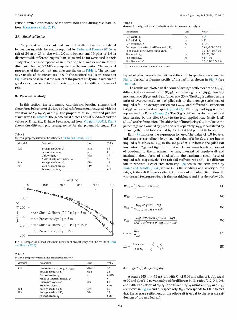
Table 3Geometric configurations of piled-raft model for parametric analysis.
Parameters Unit Value
Raft width, Br m 45a
Raft width, Lr m 45a
Raft thickness, tr m 1, 2a, 3Corresponding raft-soil stiffness ratio, Krs – 0.01, 0.09a, 0.31Piled group to raft width ratio, Bg/Br – 0.2, 0.4, 0.6a, 0.8Pile length, Lp m 10, 20, 30a
Pile spacing, Sp m 4.5a - 36Pile diameter, dp m 0.5, 1.0a, 1.5, 2.0
a Indicates standard value if not varied.
S. Mali, B. Singh Ocean Engineering 149 (2018) 205–216
cause a limited disturbance of the surrounding soil during pile installa-tion (Brinkgreve et al., 2015).
2.3. Model validation
The present finite element model in the PLAXIS 3D has been validatedby comparing with the results reported by Sinha and Hanna (2016). Araft of 24 m � 24 m size with 2.0 m thickness and 16 piles of 1.0 mdiameter with different lengths (5 m, 10 m and 15 m) were used in theirstudy. The piles were spaced at six times of pile diameter and uniformlydistributed load of 0.5 MPa was applied on the foundation. The materialproperties of the soil, raft and piles are shown in Table 1. The compar-ative results of the present study with the reported results are shown inFig. 4. It can be seen that the results of the present study are in reasonablygood agreement with that of reported results for the different length ofpiles.
3. Parametric study
In this section, the settlement, load-sharing, bending moment andshear force behavior of the large piled-raft foundation is studied with thevariation of Sp, Lp, dp and Krs. The properties of soil, raft and pile aresummarized in Table 2. The geometrical dimensions of piled-raft and thevalues of Es, Er, Krs, Ep have been selected from Viggiani (2001). Fig. 5shows the different pile arrangements for the parametric study. The
Table 1Material properties used in the validation (Sinha and Hanna, 2016).
Material Properties Unit Value
Soil Young's modulus, Es MPa 54Poisson's ratio, νs – 0.15Unit weight, γ kPa 19Angle of internal friction, φ � 20
Raft Young's modulus, Er GPa 34Pile Young's modulus, Ep GPa 25
Poisson's ratio, νp – 0.2
Fig. 4. Comparison of load settlement behavior of present study with the results of Sinhaand Hanna (2016).
Table 2Material properties used in the parametric analysis.
Material Properties Unit Value
Soil Unsaturated unit weight, γunsat kN/m3 16Young's modulus, Es MPa 25Poisson's ratio, νs – 0.495Angle of internal friction, φ � 0Undrained cohesion kPa 80Adhesion factor, α – 0.55
Raft Young's modulus, Er GPa 25Pile Young's modulus, Ep GPa 25
Poisson's ratio, νp – 0.25
208
layout of piles beneath the raft for different pile spacings are shown inFig. 6. Vertical settlement profile of the raft is as shown in Fig. 7 (seeTable 3).
The results are plotted in the form of average settlement ratio (Ravg),differential settlement ratio (Rdiff), load-sharing ratio (GPR), bendingmoment ratio (RBM) and shear force ratio (RSF). The Ravg is defined as theratio of average settlement of piled-raft to the average settlement ofunpiled-raft. The average settlement (Wavg) and differential settlement(Wdiff) are expressed in Eqns. (3) and (4). The Ravg and Rdiff and arerepresented by Eqns. (5) and (6). The GPR is defined as the ratio of totalload carried by the piles (Rpile) to the total applied load (static load)(Rtotal) on the foundation. The objective of introducingGPR is to know thepercentage load carried by piles and raft, separately. Rpile is calculated bysumming the axial load carried by the individual piles at its head.
Eqn. (7) indicates the expression for GPR. The value of 1.0 for GPR,indicates a freestanding pile group, and value of 0 for GPR, describes anunpiled-raft; whereas, GPR in the range of 0–1 indicates the piled-raftfoundation. RBM and RSF are the ratios of maximum bending momentof piled-raft to the maximum bending moment of unpiled-raft andmaximum shear force of piled-raft to the maximum shear force ofunpiled-raft, respectively. The raft-soil stiffness ratio (Krs) for differentraft thicknesses is calculated from Eqn. (8) which has been given byFraser and Wardle (1976).where Er, is the modulus of elasticity of theraft, vr is the raft Poisson's ratio, Es is the modulus of elasticity of the soil,vs is the soil Poisson's ratio, tr is the raft thickness and Br is the raft width.
Wavg ¼ 13ð2wcenter þ wcornerÞ (3)
Wdiff ¼ wcenter � wcorner (4)
Ravg ¼ Wavg of piled � raftWavg of unpiled � raft
(5)
Rdiff ¼ Diff :settlement of piled � raf tDiff : settlement of unpiled � raft
(6)
GPR ¼ Rpile
Rtotal(7)
Krs ¼4� Er �
�1� v2s
�
3� Es
�1� v2r
� � t3rB3r
(8)
3.1. Effect of pile spacing (Sp)
A square (45 m � 45 m) raft with Krs of 0.09 and piles of Lp/dp equalto 30 and dp of 1.0 mwas analyzed for different Bg/Br ratios (0.2, 0.4, 0.6,and 0.8). The effects of Sp/dp for different Bg/Br ratios on Ravg and Rdiffare shown in Fig. 8a and b, respectively. Ravg corresponds to 1.0 indicatesthat the average settlement of the piled-raft is equal to the average set-tlement of the unpiled-raft.

Fig. 5. Pile arrangements for parametric study.
S. Mali, B. Singh Ocean Engineering 149 (2018) 205–216
209

Fig. 6. Half layout of piles in the piled-raft for different pile spacings.
Fig. 7. Definition of raft settlement.
Fig. 8. Effect of pile spacing on (a) average settlement ratio and (b) differential settle-ment ratio.
S. Mali, B. Singh Ocean Engineering 149 (2018) 205–216
It can be seen that with increase in Sp/dp from zero, Ravg decreases fordifferent Bg/Br ratios and the decrease is noted to be more for higher Bg/Br ratio of 0.8 (Fig. 8(a)). For any Bg/Br ratio the Ravg attains a minimumvalue at Sp/dp ¼ 5–6 (approx.) and then afterword it increases gradually.Beyond Sp/dp of 5–6, the number of piles decreases and also a group ofpiles might have started to behave as individual pile elements. Thus, fromthe average settlement point of view, the Sp/dp of 5–6 can be consideredas optimum value.
As the Sp/dp increases, Rdiff decreases for different Bg/Br ratios andthe decrease is noted to be more for lower Bg/Br ratio of 0.2 (Fig. 8(b)).Rdiff corresponds to 1.0 indicates that the differential settlement of thepiled-raft is equal to the differential settlement of the unpiled-raft. At anyBg/Br ratio, Rdiff decreases initially up to Sp/dp ¼ 6 (approx.) and sub-sequently increases. At Bg/Br ratios of 0.2 piles are mostly concentratednear the central portion of the raft due to which Rdiff decreases. Forminimizing the differential settlement, pile should be placed near thecentral portion of the raft with Sp/dp of 5–6.
Fig. 9 shows the Effect of pile spacing on average settlement ratio fordifferent raft-soil stiffnesses and Bg/Br ratios. It can be observed that forsame Sp/dp and Bg/Br ratio, with increase in raft-soil stiffness ratio (Krs),Ravg increases. For same Krs, with increase in Bg/Br ratio, Ravg is observedto be decreases. Therefore, raft with smaller Krs and larger Bg/Br ratio canbe selected to decrease the Ravg effectively. Fig. 10 shows the load-settlement plot for piled-raft (PR), pile group (PG), unpiled-raft (UR),raft in piled-raft (Rpr), and piles in piled-raft (Gpr). It can be seen that theload carried by PG and UR is higher than that of Gpr and Rpr, respectively.Such behavior may be due to the interaction of piles and raft in piled-raft.
210
At any settlement value the load carried by PR is equal to the load carriedby Rpr and Gpr.
Fig. 11 shows the effect of Sp/dp on GPR for different Bg/Br ratios. GPRof 1.0 indicates that the total load of the superstructure is carried by thepiles only. It can be seen that as the Sp/dp increases from 4 to 36, GPRdecreases linearly. Since, with increase in Sp/dp, the number of pilesdecreases; consequently, the contact pressure beneath the raft increases.
The effect of Sp/dp on RBM and RSF for different Bg/Br ratios is shownin Fig. 12(a) and (b), respectively. At any Bg/Br ratio, with increase in Sp/dp, RBM decreases initially up to Sp/dp ¼ 5 (approx.) and thereafter itincreases (Fig. 12(a)). At same Sp/dp, RBM is observed to be less for lowerBg/Br ratio. Like differential settlement, for bending moment, pile shouldbe placed near the central portion of the raft with lower Sp/dp ratio. Forany Bg/Br ratios, with increase in Sp/dp, RSF increases gradually. At sameSp/dp, RSF is observed to be lesser for higher Bg/Br ratio (Fig. 12(b)). (seeFig. 14)
3.2. Effect of pile length (Lp)
In order to understand the effect Lp, simulations were carried on apiled-raft with Lp/dp of 10, 20 and 30, and piles were spaced at Sp ¼ 5dp.Fig. 13(a) and (b) show the effect of Lp/dp on Ravg and Rdiff for differentBg/Br ratios. The results show that Ravg decreases with increase in Lp/dpfor every Bg/Br ratios. The decrease in settlement is attributed to theincrease in the amount of skin friction with increase in Lp/dp. In additionto this, the decrease of Ravg observed to be more for larger Bg/Br ratio of0.8 (Fig. 13(a)). Therefore, to minimize Ravg, the more numbers of pileswith longer lengths are the most effective. In comparison with the Ravg,the trends of decrease in Rdiff for different Bg/Br ratio are dissimilar

Fig. 9. Effect of pile spacing on average settlement ratio for different raft-soil stiffnesses and Bg/Br ratios.
Fig. 10. Load-settlement relationship for the piled raft (PR), pile group (PG), unpiled-raft(UR), pile group in piled raft (Gpr) and raft in piled-raft (Rpr).
Fig. 11. Effect of pile spacing on load-sharing ratio and for different Bg/Br ratios.
Fig. 12. Effect of pile spacing and Bg/Br on (a) bending moment ratio and (b) shearforce ratio.
S. Mali, B. Singh Ocean Engineering 149 (2018) 205–216
(Fig. 13(b)). Rdiff decreases with increase in Lp/dp for Bg/Br ratio of 0.2and 0.6, then it increases for Bg/Br¼ 0.8. Fig. 13 presents the effect of Lp/dp on GPR for different Bg/Br ratios. As expected, the GPR increases line-arly as the Lp/dp increases and the increase is more at higher Lp/dp.Fig. 15 shows the combined effect of effect of Lp/dp and Bg/Br ratios onRBM and RFM. With increase in Bg/Br ratios, RBM decreases initially up toBg/Br¼ 0.6 and thereafter increases for every Lp/dp (Fig. 15(a)). Thus, forminimum RBM, higher Lp/dp can be selected. With increase in Bg/Br, RSFincreased gradually for all Lp/dp (Fig. 15(b)). Thus, for minimum RSF, itcan be suggested to select lower Lp/dp.
211
3.3. Effect of pile diameter (dp)
In order to understand the effect of dp, simulations were conducted ona piled-raft with varying dp from 0.5 to 2.0 m. It can be observed that Ravgdecreases as the dp increases (Fig. 16(a)). An increase in dp (up to 1.0 mfor Bg/Br ¼ 0.6 and 0.8) might attributed the increased stiffness of thepile-raft. At dp equal to 1.0 m, the piled-raft system might have achievedthe maximum stiffness. The effect of dp on Rdiff is plotted in Fig. 16(b). Asthe Bg/Br ratio changes from 0.2 to 0.6, the Rdiff decreases up todp ¼ 1.0 m and it remains constant thereafter. As the Bg/Br ratio changesfrom 0.6 to 0.8, Rdiff increases significantly for every pile diameter.

Fig. 13. Effect of pile length on (a) average settlement ratio and (b) differential settle-ment ratio.
Fig. 14. Effect of pile length on load-sharing ratio.
Fig. 15. Effect of pile length and Bg/Br on (a) bending moment ratio and (b) shearforce ratio.
S. Mali, B. Singh Ocean Engineering 149 (2018) 205–216
Fig. 17 shows the variation of GPR with dp for different Bg/Br ratios. Withincrease in dp, GPR increases and the increase is noted to be marginalbeyond dp of 1.0 m for every Bg/Br ratios.
Fig. 18 shows the combined effect of dp and Bg/Br ratios on RBM andRFM. RBM decreases as the Bg/Br decreases up to 0.6, and thereafter itincreases. Also it can be seen that RBM was higher at dp¼ 4.0 and lower atdp ¼ 1.0 (Fig. 18(a)). Fig. 18(b) shows the variation of RSF with dp fordifferent Bg/Br ratios. With increase in Bg/Br, for every dp, RSF increasesup to Bg/Br ¼ 0.2 and decreases thereafter. Thus, for minimum RSF, lesserdp with higher Bg/Br ratio can be selected.
212
3.4. Effect of raft-soil stiffness ratio (Krs)
In this series, simulations were carried on a piled-raft by varying Krs
from 0.01 to 0.32 Krs have been varied by varying the thickness of the raftfrom 1 to 3 m. Fig. 19(a) and (b) shows the bending moment and shearforce variation along the entire width of raft for different Krs at Bg/Br ¼ 0.6. It was noted that in unpiled-raft and piled-raft, the bendingmoment was maximum at the center of the raft (except Krs ¼ 0.01) and itdecreases to zero at the edge of raft (Fig. 19(a)). For same raft-soilstiffness ratio (Krs ¼ 0.09), the bending moment response of piled-raftis dissimilar as that of unpiled-raft. From 22.5 m to 9 m span of theraft, bending moment decreases and from 9 m to 3 m span it increasesand again it decreases towards the left edge of the raft.
The shear force is minimum at the center of the raft (22.5 m) and itattains maximum values at 12 m, 6 m and 0 m (Fig. 19(b)). The piles arelocated at a distance of 9 m, 13.5 m, 18 m and 22.5 m (Fig. 6). In general,at any Krs the shear force changes its sign in the vicinity of the edge pile.Fig. 20(a) shows the combined effect of Krs and Bg/Br on maximumbending moment (Mmax) of raft and maximum shear force (τmax) of raft.With increase in Bg/Br, Mmax decreases initially up to Bg/Br of 0.6 andafter that increases for every Krs values. With variation of Bg/Br ratio fordifferent Krs values, similar trends are observed for τmax (Fig. 20(b)).
3.5. Behavior of piles in piled-raft
In order understand the behavior of piles in piled-raft, simulationswere carried on the piled-raft with Lp/dp ¼ 40 for different Bg/Br ratios of0.2, 0.6 and 0.8. Middle pile, edge pile and corner piles are abbreviated as

Fig. 16. Effect of pile diameter on (a) average settlement ratio and (b) differential set-tlement ratio. Fig. 18. Effect of pile diameter and Bg/Br ratios on (a) bending moment ratio and (b)
shear force ratio.
S. Mali, B. Singh Ocean Engineering 149 (2018) 205–216
MP, EP and CP, respectively. The pile abbreviated as MP_0.6, indicatesthe middle pile with Bg/Br ratio of 0.6. Fig. 21 shows the variation ofvertical settlement and lateral displacement along the depth of piles. Itcan be seen that vertical settlement of piles is more at the head of the pileand it decreases nominally towards the tip of the pile (Fig. 21(a)). Thevertical settlement is observed to be more in CP_0.2 and is less in CP_1.0.The settlement in corner pile is observed to be more for Bg/Br ratios of0.2, because of lesser number of piles.
It can also be seen that of the piles are displaced laterally at its tip andthe lateral displacement of pile is observed to be more in EP_1.0(Fig. 21(b)). For smaller Bg/Br ratios, the lateral displacement of pile is
Fig. 17. Effect of pile diamet
213
noted to be lesser than that of larger Bg/Br ratio. At lower Bg/Br ratio,piles in piled-raft may possess greater soil confinement. Variation of axialforce along the depth of piles is shown in Fig. 22. The axial force in thepile is observed to be higher at the head of pile and decreases towards thetip of the piles. The axial force in CP_0.2 is observed to be higher andMP_1.0 carried lesser axial force. For smaller Bg/Br ratio, the axial forcesin the piles are noted to be higher than as that of larger Bg/Br ratios.
The distribution of bending moment along the depth of piles is shownin Fig. 23(a). It can be seen that the bending moment is observed to bemore at the head of piles and decreases to zero at the tip of the piles. The
er on load-sharing ratio.

Fig. 19. Effect of raft-soil stiffness ratio on (a) bending moment and (b) shear force alongthe width of the raft (Np ¼ 49, Sp ¼ 4.5 m, Bg/Br ¼ 0.6).
Fig. 20. Effect of raft-soil stiffness ratio and Bg/Br ratios on (a) maximum bendingmoment and (b) maximum shear force of raft.
S. Mali, B. Singh Ocean Engineering 149 (2018) 205–216
bending moment in pile might be induced due to the lateral movement ofthe soil. The EP_1.0 carried higher bending moment followed by CP_0.8.Fig. 23(b) shows the distribution of shear force along the depth of piles.Shear force in the piles were observed to be higher at the head anddecreased to zero (approx.) at the tip of the piles. Likewise, bendingmoment, the shear force in EP_0.8 was observed to be more.
4. Conclusions
A series of 3-D numerical analysis were carried out on a large piled-raft foundation in a clay soil under the action vertical loading. The ef-fect of pile spacing (Sp), pile length (Lp), pile diameter (dp) and raft-soilstiffness ratio (Krs) on the settlement, load-sharing, bending momentand shear force behavior of the large piled-raft foundation were inves-tigated. Based on the results of the present study, the following conclu-sions are drawn.
1. For any pile group to raft width ratio, with increase in pile spacing todiameter ratio, average settlement ratio, differential settlement ratio,and bending moment ratio decreases up to the pile spacing of 5–6times the pile diameter and then increases. Also, load-sharing ratiodecreases and shear force ratio increases. Raft with smaller raft-soilstiffness ratio and larger pile group to raft width ratio observed tobe effective in decreasing the average settlement ratio. Raft and pilegroup in piled-raft has carried fewer loads as that of unpiled raft andfree standing pile groups.
2. For any pile group to raft width ratio, with increase in pile length todiameter ratio, average settlement ratio, differential settlement ratio
214
decreases and load-sharing ratio increase. Also, the bending momentratio decreases up to Bg/Br ¼ 0.6 and thereafter it increases, whereasshear force ratio increases linearly.
3. With increase in pile diameter, average settlement ratio and differ-ential settlement ratio decreases and load-sharing ratio increases (upto pile diameter 1.0). For any pile group to raft width ratio, with in-crease in pile diameter from 0.5 to 1.0 m, the bending moment ratiodecreases and increases thereafter. For any pile diameter, the shearforce ratio increases up to pile group to raft width ratio of 0.2 andthen it decreases.
4. In unpiled-raft and piled-raft, maximum bending moment and mini-mum shear force is obtained at the center of the raft. The bendingmoment was affected marginally when raft-soil stiffness increasesmore than 0.09. The shear force increase as the raft-soil stiffness ratioincrease. At any raft-soil stiffness ratio, shear force at the edge pile isnoted to be minimal as compared to inside piles. Also, shear forcechanges its sign in the vicinity of edge pile. As the raft-soil stiffnessratio increases, the maximum bending moment and maximum shearforce in the raft increases.
5. The vertical settlement of piles is more at its head and less at its tip,whereas the lateral displacement in piles is more at its tip. Corner pilewith pile group to raft width ratio of 0.2, settle more and the lateraldisplacement is more in pile group to raft width ratio of 0.8. The axialforce, bending moment and shear force in piles are more at its headand less at its tip. Axial force is more in corner pile with pile group toraft width ratio of 0.2 and is lesser in middle pile with pile group toraft width ratio 1.0. Edge pile with pile group to raft width ratio of 0.8carries higher bending moment and shear force.

Fig. 21. Variation of (a) vertical settlement and (b) lateral displacement along the depthof piles.
Fig. 22. Variation of axial force along the depth of piles.
Fig. 23. Variation of (a) bending moment and (b) shear force along the depth of piles.
S. Mali, B. Singh Ocean Engineering 149 (2018) 205–216
References
Baguelin, F., Frank, R., 1982. Theoretical Studies of Piles Using the Finite ElementMethod, Foundation Engineering. Georges Pilot. Presses Ponts et Chauss�ees.
Brinkgreve, R., Swolfs, W., Engin, E., 2015. PLAXIS User's Manual. Balkema, Rotterdam,The Netherlands, version 6.1. .
Burland, J., 1977. Piles as settlement reducers. In: Proc., 19th National ItalianGeotechnical Conference Padova, Italy, vol. 2, pp. 21–34.
Cho, J., Lee, J., Jeong, S., Lee, J., 2012. The settlement behavior of piled raft in clay soils.Ocean Eng. 153–163.
Fraser, R.A., Wardle, L.J., 1976. Numerical analysis of rectangular rafts on layeredfoundations. Geotechnique 26 (4), 613–630.
Gandhi, S.R., Maharaj, D.K., 1995. Behavior of piled raft under uniform loading. In: Proc.Indian Geotechnical Conference (IGC-95), Bangalore, vol. 1, pp. 169–172.
Ghalesari, A.T., Barari, A.P., Fardad Amini Ibsen, L.B., 2015. Development of optimumdesign from static response of pile-raft interaction. J. Mater. Sci. Technol. 20,331–343.
215
Jeong, S., Lee, J., Lee, C.J., 2004. Slip effect at the pile-soil interface on dragload. Comput.Geotech. 31 (2), 115–126.
Lee, J., Kim, Y., Jeong, S., 2010. Three dimensional analysis of bearing behavoir of piledraft on soft clay. Comput. Geotech. 37, 103–114.
Mandolini, A., Di Laora, R., Mascarucci, Y., 2013. Rational design of piled raft. ProcediaEngineering 57, 45–52.
Nguyen, D.D.C., Kim, D.S., Jo, S.B., 2014. Parametric study for optimal design of largepiled raft foundations on sand. Comput. Geotech. 55, 14–26.
Oh, E.Y.N., Huang, C., Surarak, C., Adamec, R., Balasurbamaniam, A.S., 2008. Finiteelement modeling for piled raft foundation in sand. In: 11th East Asia-PacificConference on Structural Engineering and Construction, Taiwan, pp. 19–21.
Poulos, H.G., 2001. Methods of Analysis of Piled Raft Foundations. A Report Prepared onBehalf of Technical Committee TC18 on Piled Foundations.
Poulos, H.G., Bunce, G., 2008. Foundation design for the Burj Dubai: the world tallestbuilding. In: Proc.,The Sixth International Conference on Case Histories inGeotechnical Engineering, Arlinton, VA, pp. 11–16.

S. Mali, B. Singh Ocean Engineering 149 (2018) 205–216
Poulos, H.G., Devdas, A.J., 2005. Foundation design for the Emirates twin towers. Dubai.Candian Geotech. J. 42, 716–730.
Poulos, H.G., Small, J.C., Chow, H., 2011. Piled raft foundation for tall buildings.Geotech. Eng. J. SEAGS AGSSEA 42 (2), 78–84.
Prakoso, W.A., Kulhawy, F.H., 2001. Contribution to piled raft foundation design.J. Geotech. Geoenviron. Eng. 127 (1), 17–24.
Rabiei, M., Choobbasti, A.J., 2016. Piled raft design strategies for high rise buildings.Geotech. Geol. Eng. 34, 75–85.
Ranjan, G., Rao, A.S.R., 2007. Basic and applied soil mechanics. New Age International.Reul, O., 2004. Numerical study of the bearing behavior of piled rafts. Int. J. GeoMech. 4
(2), 59–68.Reul, O., Randolph, M.F., 2004. Design strategies for piled rafts subjected to nonuniform
vertical loading. J. Geotech. Geoenviron. Eng. 130, 1–13.
216
Sanctis, L.D., Mandolini, A., 2006. Bearing capacity of the piled rafts on soft clays.J. Geotech. Geoenviron. Eng. 132, 1600–1610.
Seo, Y.K., Choi, K.S., Jeong, S.G., 2003. Design charts of piled raft foundations on softclay. In: Proc., the Thirteenth International Offshore and Polar EngineeringConference, Hawaii, USA, pp. 753–755.
Shrestha, S., Nadarajah, R., Parishad, R., 2017. Robust Geotechnical Design of Piled-raftFoundations for Tall Onshore Wind Turbines. Geotechnical Frontiers, pp. 204–213.
Sinha, A., Hanna, A.M., 2016. 3D Numerical model for piled raft foundation. Int. J.GeoMech. https://doi.org/10.1061/(ASCE)GM.1943-5622.0000674.
Viggiani, C., 2001. Analysis and Design of Piled Raft Foundations. First Arrigo CroceLecture. Rivista Italiana Di Geotechnica, pp. 47–75.