BEHAVIOR OF BEAM AND AW LL OUTRIGGER IN HIGH -RISE …. IJCSEIERD - Behavior of... · BEHAVIOR OF...
12
www.tjprc.org [email protected] BEHAVIOR OF BEAM AND WALL OUTRIGGER IN HIGH -RISE BUILDING AND THEIR COMPARISON RAAD ABED AL-JALLAL HASAN Acharya Nagarjuna University , College of Engineering and Technology, Department of Civil, Guntur, A.P, India ABSTRACT Tall buildings need a lateral load resisting system to resist the lateral loads induced by wind or earthquake forces. One of the most efficient systems is outrigger. Outriggers are structural systems that support building against lateral loads. Outriggers are rigid horizontal structures designed to improve building overturning stiffness and strength. This paper provides an overview of outrigger systems and studying the comparison of beam and wall outrigger. A three structures of 30 story building was investigated in this research study. Response spectrum analysis was conducted and the behavior of the buildings was determined considering response parameters such as lateral displacement and story drift. It has been shown from this study that the structure with wall outrigger is more efficient than the structure with beam outrigger. One of the most effective techniques is the use of outrigger in structures that can astutely solve the above issues in high-rise constructions. KEYWORDS: High Rise Building, Lateral Load, Beam Outriggers, Wall Outriggers, ETABS Received: Nov 09, 2015; Accepted: Nov 25, 2015; Published: Jan 08, 2016; Paper Id.: IJCSEIERDFEB20163 INTRODUCTION High Rise Building It is difficult to distinguish the characteristics of a building which categorize it as high the outward appearance of highness is a relative matter. In Europe, a 20 –story building in a city may be called a high rise, but the citizens of small town may point to their skyscraper of six floors. In large cities, which are comprised of a vast number of high rise buildings, a structure must pierce the sky a round 70-100 story if it is to appear tall in comparison with its immediate neighbor. Definition of High Rise Building High rise building cannot be defined in specific terms related to height or number of floors. From the structural design point of view, it is simpler to consider the building as high when its structural analyses and design are in some way affected by the lateral loads particularly the drift caused by such loads. Classification of High Rise Building Structural systems of tall buildings can be divided into two broad categories: interior structures and exterior structures. Tables 1 and 2 summarize the details of the systems in each category. In addition, Figure 1 and 2 show the concept of each system diagrammatically. Original Article International Journal of Civil, Structural, Environmental and Infrastructure Engineering Research and Development (IJCSEIERD) ISSN(P): 2249-6866; ISSN(E): 2249-7978 Vol. 6, Issue 1, Feb 2016, 19-30 © TJPRC Pvt. Ltd.
Transcript of BEHAVIOR OF BEAM AND AW LL OUTRIGGER IN HIGH -RISE …. IJCSEIERD - Behavior of... · BEHAVIOR OF...

www.tjprc.org [email protected]
BEHAVIOR OF BEAM AND WALL OUTRIGGER IN HIGH -RISE
BUILDING AND THEIR COMPARISON
RAAD ABED AL-JALLAL HASAN
Acharya Nagarjuna University , College of Engineering and Technology, Department of Civil, Guntur, A.P, India
ABSTRACT
Tall buildings need a lateral load resisting system to resist the lateral loads induced by wind or earthquake
forces. One of the most efficient systems is outrigger. Outriggers are structural systems that support building against
lateral loads. Outriggers are rigid horizontal structures designed to improve building overturning stiffness and strength.
This paper provides an overview of outrigger systems and studying the comparison of beam and wall outrigger. A three
structures of 30 story building was investigated in this research study. Response spectrum analysis was conducted and
the behavior of the buildings was determined considering response parameters such as lateral displacement and story
drift. It has been shown from this study that the structure with wall outrigger is more efficient than the structure with
beam outrigger. One of the most effective techniques is the use of outrigger in structures that can astutely solve the
above issues in high-rise constructions.
KEYWORDS: High Rise Building, Lateral Load, Beam Outriggers, Wall Outriggers, ETABS
Received: Nov 09, 2015; Accepted: Nov 25, 2015; Published: Jan 08, 2016; Paper Id.: IJCSEIERDFEB20163
INTRODUCTION
High Rise Building
It is difficult to distinguish the characteristics of a building which categorize it as high the outward
appearance of highness is a relative matter. In Europe, a 20 –story building in a city may be called a high rise, but
the citizens of small town may point to their skyscraper of six floors. In large cities, which are comprised of a vast
number of high rise buildings, a structure must pierce the sky a round 70-100 story if it is to appear tall in
comparison with its immediate neighbor.
Definition of High Rise Building
High rise building cannot be defined in specific terms related to height or number of floors. From the
structural design point of view, it is simpler to consider the building as high when its structural analyses and design
are in some way affected by the lateral loads particularly the drift caused by such loads.
Classification of High Rise Building
Structural systems of tall buildings can be divided into two broad categories: interior structures and
exterior structures. Tables 1 and 2 summarize the details of the systems in each category. In addition, Figure 1 and
2 show the concept of each system diagrammatically.
Original A
rticle
International Journal of Civil, Structural, Environmental and Infrastructure Engineering Research and Development (IJCSEIERD) ISSN(P): 2249-6866; ISSN(E): 2249-7978 Vol. 6, Issue 1, Feb 2016, 19-30 © TJPRC Pvt. Ltd.

20
Impact Factor (JCC): 5.9234
Figure 1: Classifi FazlurKhan
Category Sub-
Category Material/
Configuration
Rigid Frames
Concrete ــــــــــــ
Braced Hinged Frames
ـــــــــــــ Steel Shear Trusses + Steel Hinged Frames
(JCC): 5.9234
Classification of Tall Building Structural Systems byFazlurKhan (above: Steel; below: Concrete)
Figure 2: Interior Structures
Table 1: Interior Structures
Material/ Configuration
Efficient Height Limit
Advantages
20 Provide flexibility in floor planning. Easily moldable
Steel Shear Trusses + Steel Hinged Frames
10
Efficiently resist lateral loads by axial forces in the shear truss members. Allows shallower beams compared with the rigid frames without diagonals.
Raad Abed Al-Jallal Hasan
NAAS Rating: 3.01
by
Disadvantages
Expensive form work. Slow construction.
Interior planning limitations due to diagonals in the shear trusses. Expensive diagonal connections.

Behavior of Beam and Wall Outrigger in High Rise Building and their Comparison 21
www.tjprc.org [email protected]
Table 1: Contd., Shear Wall/ Hinged Frames
ـــــــــــــConcrete Shear wall + Steel Hinged Frame
35 Effectively resists lateral shear by concrete shear walls.
Interior planning limitations due to shear trusses.
Shear Wall (or Shear Truss – Frame Interaction System
Shear wall / Rigid Frame
Concrete Shear wall + Steel Rigid frame
60
Effectively resists lateral loads by producing shear wall – frame interacting system.
Interior planning limitations due to shear walls.
Concrete Shear wall + concrete frame
70 Effectively resists lateral loads by shear wall – frame interacting system.
Interior planning limitations due to shear walls.
Outrigger Structures
ــــــــــــ
Shear Cores(Steel Trusses or Concrete shear walls) + Outriggers (Steel Trusses or Concrete walls) +Belt Trusses) +Steel or Concrete Composite (Super) Columns
150
Effectively resists bending by exterior columns connected to outriggers extended from the core.
Outrigger structure does not add shear resistance.
Table 2: Exterior Structures
Category Sub-
Category Material/
Configuration
Efficient Height Limit
Advantages Disadvantages
Tube
Framed Tube
Concrete 60
Effectively resists lateral loads by locating lateral systems at the building perimeter.
Shear lag hinders true tubular behavior. Narrow column spacing obstructs the view.
Braced Tube
Concrete 100
Effectively resists lateral shear by axial forces in the diagonal members. Wider column spacing possible compared with framed tubes. Reduced shear lag.
Bracing obstructs the view.
Bundled Tube
Concrete 110 Reduced shear lag.
Interior planning limitations due to the bundled tube configuration.
Tube in Tube
Ext. Frame tube(Steel or Concrete) +Int. Core Tube( Steel or Concrete)
80
Effectively resists lateral loads by producing interior shear core – exterior framed tube interacting system.
Interior planning limitations due to shear core.
Diagrid ـــــــــــــ Concrete 60
Effectively resists lateral shear by axial forces in the diagonal members.
Expensive form work. Slow construction.
Super frames
Concrete 100 ـــــــــــــCould produce super tall buildings.
Building form depends to a great degree on the structural system.

22 Raad Abed Al-Jallal Hasan
Impact Factor (JCC): 5.9234 NAAS Rating: 3.01
Outrigger and Belt Wall System
The structural arrangement for this system consists of a main concrete core connected to exterior columns by
relatively stiff horizontal members such as a one or two-story deep walls commonly referred to as outriggers. The basic
structural response of the system is quite simple. When subjected to lateral loads. The external moment is now resisted not
by bending of the core alone, but also by the axial tension and compression of the exterior columns connected to the
outriggers. As a result, the effective depth of the structure for resisting bending is increased when the core flexes as a
vertical cantilever, by the development of tension in the windward columns, and by compression in the leeward columns.
This is achieved by tying the exterior columns with a one- or two-story deep wall commonly referred to as a “belt wall,”
around the building. To achieve efficiency, the outriggers and belt walls are made one—and often two—stories deep with
door-size openings in the outriggers for circulation. It is also possible to use vierendeel frames extending through several
floors to act as outriggers, as shown in. Yet another option is to use girders, such as haunch girders, at each floor. It should
be noted that whereas the outrigger is effective in increasing the structure’s flexural stiffness, it does not increase resistance
to shear, which must be carried only by the core. To understand the behavior of an outrigger system, consider a building
stiffened by a story-high outrigger wall at top. Because the outrigger is at the top, the system is often referred to as a cap or
hat wall system. The tie-down action of the cap wall generates a restoring couple at the building top, resulting in the
occurrence of a point of contra flexure some distance from the top. The resulting reversal in curvature reduces the bending
moment in the core and hence the Building drift. Of the outrigger wall. This idealization is not necessary in developing the
theory, but keeps the explanation simple. Therefore, the cap wall may be conceptualized as a restraining spring located at
the top of the shear core.
Optimum Locations of Two Outriggers
In the preceding conceptual analyses, only one compatibility equation was necessary because the one-outrigger
structure is once-redundant. On the other hand, a two-outrigger structure is twice redundant, requiring a solution of two
compatibility equations. To seek a solution to the problem, we proceed as before assuming the sectional areas of the
exterior columns and the moment of inertia of the core decrease linearly up the height. A trapezoidal distribution is
assumed, as before, for the lateral load. Schematics of conceptual analytical model and behavior of the structural system
are shown in Figures 3. The method of analysis for calculating the deflections at the top is similar to that used for the single
outrigger. The moments at the outrigger locations are chosen as the unknown arbitrary constants M1 and M2, see Figure 4.
The structure is then rendered statically determinate by removing the rotational restraints at the outrigger
locations. Next, the compatibility equations for the rotations at the truss locations are set up and solved simultaneously to
obtain the values to M1 and M2. The final deflection at the top is obtained by a superposition of the deflection due to the
external load and a counteracting deflection due to the moments M1 and M2. The resulting deflections are summarized in
Figure 5.

Behavior of Beam and Wall Outrigger in High Rise Building and their Comparison
www.tjprc.org
Figure 3: Building
Figure 4:
Optimum Locations of Outrigger Trusses
It’s been recommended that the optimum level of t
approximately mid-height (Figure 6). A two outrigger system would have one placed at 1/3 and the other placed at 2/3 of
the Building height [30]. For a three-outrigger system, they should
for the optimum performance of an n-outrigger structure, the outriggers should be placed at 1/n + 1, 2/n + 1, 3/n + 1, 4/n +
1… n/n + 1 height locations.
Behavior of Beam and Wall Outrigger in High Rise Building and their Comparison
Building with Outrigger and Bet Truss at Two Location
Figure 4: Method of Analyses of Two Outrigger System
Outrigger Trusses
It’s been recommended that the optimum level of the outriggers for minimizing the drift for a single outrigger is at
). A two outrigger system would have one placed at 1/3 and the other placed at 2/3 of
outrigger system, they should be at the 1/4, 1/2, and 3/4 heights, and so on. Therefore,
outrigger structure, the outriggers should be placed at 1/n + 1, 2/n + 1, 3/n + 1, 4/n +
23
Two Location
he outriggers for minimizing the drift for a single outrigger is at
). A two outrigger system would have one placed at 1/3 and the other placed at 2/3 of
be at the 1/4, 1/2, and 3/4 heights, and so on. Therefore,
outrigger structure, the outriggers should be placed at 1/n + 1, 2/n + 1, 3/n + 1, 4/n +
24
Impact Factor (JCC): 5.9234
Figure 5: Optimum (b)
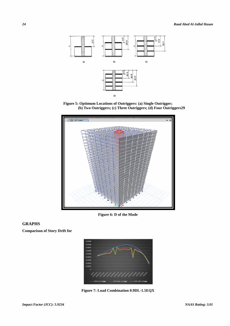
GRAPHS
Comparison of Story Drift for
Figure 7:
(JCC): 5.9234
Optimum Locations of Outriggers: (a) Single Outrigger(b) Two Outriggers; (c) Three Outriggers; (d) Four Outriggers29
Figure 6: D of the Mode
Figure 7: Load Combination 0.9DL-1.5EQX
Raad Abed Al-Jallal Hasan
NAAS Rating: 3.01
Single Outrigger; Four Outriggers29

Behavior of Beam and Wall Outrigger in High Rise Building and their Comparison 25
www.tjprc.org [email protected]
Comparison of Shear Force for C1
Figure 8: Load combination 0.9DL-1.5EQX
Figure 9: Load Combination 1.2(DL+LL+EQX)
Figure 10: Load Combination (0.9DL-1.5EQX)
Comparison of Torsion for C1
Figure 11: Load combination 1.2(DL+LL+EQX)

26 Raad Abed Al-Jallal Hasan
Impact Factor (JCC): 5.9234 NAAS Rating: 3.01
Figure 12: Load Combination (0.9DL-1.5EQX)
Comparison of Bending Moment for C1
• Without outrigger.
• With beam outrigger.
• With wall outrigger.
Figure 13: Load Combination 1.2(DL+LL+EQX)
Figure 14: Load Combination (0.9DL-1.5EQX)
CONCLUSIONS
This paper has presented a comparison of beam and wall outrigger structural systems for high rise buildings. The
design of tall structures is controlled by three governing factors, strength, drift, maximum lateral displacement. The

Behavior of Beam and Wall Outrigger in High Rise Building and their Comparison 27
www.tjprc.org [email protected]
outrigger concept is in wide spread use today in the design of tall buildings. In this concept outrigger beam or wall should
connect lateral load resisting core to the columns at the exterior of the building. The core consist of shear walls. The use of
beam or wall outrigger system in high-rise buildings increase the stiffness and makes the structural form efficient under
lateral load.
The analysis is carried out for study of rigid core and floor rigidity of 30 story building for the following
structures:-
Structure 1: Building frame without outrigger.
Structure 2: Building frame with beam outrigger and belt truss.
Structure 3: Building frame with wall outrigger and belt wall.
Both beam and wall outrigger are provided at the first third and second third of the structure height. According to
Bungale S. Taranath theory, the outriggers should be placed at (1/n + 1), (2/n + 1), (3/n + 1), (4/n + 1)… (n/n + 1) height
locations. The optimum location for a two-outrigger structure is at one-third and two-third heights.
From the analysis of the Data the following conclusions have been made:-
• The use of outrigger system in high-rise buildings increase the stiffness and makes the structural form efficient
under lateral load.
• Drift in all of the systems is less than the prescribed limit of H/500.
• Due to presence of the wall outrigger and belt wall in Structure 3, it is Stiffer Structure when compared to
structure with beam outrigger and belt truss. This is reflected in reduction of story displacement and story drift
values.
• The drift in the structure 3 (with wall outrigger) less than in structure 2(with beam outrigger).
• The displacement in the structure 3 (with wall outrigger) less than in structure 2(with beam outrigger).
• Moment at the base of the structure 3 (with wall outrigger) less than in structure 2(with beam outrigger).
Scope for Further Study
Outriggers are a common method of stiffening and strengthening tall buildings. They work by connecting the
inner core to the outer perimeter columns, when the structure is subjected to lateral forces, the outrigger and the columns
resist the rotation of the core and thus significantly reduce the lateral deflection and base moment. The research program
cannot solve outrigger design and construction challenges since they include a variety of situations and solutions, with new
concepts being developed. Construction will always reflect location specific preferences, abilities and limitation.
Several other subjects related to this research have been identified that it needs further investigation. Experimental
and analytical research works needed later are summarized below.
• Placement of outrigger and belt truss on different locations of building height. These can be placed individually or
in combination.
• Type of truss outrigger can be changed and a study can be made.

28 Raad Abed Al-Jallal Hasan
Impact Factor (JCC): 5.9234 NAAS Rating: 3.01
• Providing outriggers in one direction and maintaining the stability by RCC
• Core in the other direction and a study can be made.
• Deep of outrigger can be increased in to two stories and a study can be made.
• Minimize force transfer by designing for similar shortening at core-and-outrigger columns through member sizing
reinforcing, or material properties and a study can be made.
REFERENCES
1. IS 1893 (PART 1) 2002, Indian Standard Criteria for Earthquakes Resistant of Design Structures (5th revision), New Delhi,
2002.
2. IS 4326, 1993, Indian Standard Code of practice for Earthquake Resistant Design and Construction of Buildings. (2nd
revision).
3. IS 13827, 1993, Indian Standard Guidelines for improving Earthquake Resistant of Earthen buildings.
4. IS: 456 - 2000 - Code of practice for plain and Reinforced concrete.
5. IS: 875(part 1)–1987: Code of practice for design loads (Other than earthquake) for buildings and structures - Dead loads.
6. IS: 875 (part 2)–1987: Code of practice for design loads (Other than earthquake)
7. for buildings and structures – Imposed loads.
8. IS: 875(part 3) - 1987: Code of practice for design loads (Other than Earthquake) for buildings and structures - Wind loads.
9. IS 13920, 1993, Indian Standard Code for practice for Ductile Detailing of Reinforced Concrete Structures Subjected to
Seismic Forces
10. Bungale S. Taranath (1988), Structural Analysis and Design of Tall Buildings (McGraw-Hill book company).
11. BungaleS.Taranath(1998) "Steel, concrete, and composite design of tall buildings", McGraw-Hill New York.
12. Bungale S. Taranath Ph.D., S.E, Wind and Earthquake Resistant Buildings Structural Analyses and Design, Marcel Dekker
Publications, New York, 2005.
13. BungaleS.Taranath, (2010). Reinforced Concrete Design of Tall Buildings. CRC Press Taylor & Francis Group, New York.
14. BungaleS.Taranath, (2011). Structural Analysis and Design of Tall Buildings - Steel and Composite Construction. CRC Press:
Boca Raton
15. Smith, B.S. and Coull, A. (1991). Tall Building Structures: Analysis and Design. John Wiley and Sons, Inc., New York.
16. Ahsan Mohammed Khan, K. Mythili, ShaikSubhaniShareef (2014), Response Of Lateral System In High Rise Building Under
Seismic Loads, International Journal of Research and Innovation (IJRI) E-ISSN No. : 1401-1402.
17. Asif Hameed, Imran Azeem, Asad-ullahQazi, Burhan Sharif and Noor Muhammad Khan(2013), Drift and Cost Comparison of
Different Structural Systems for Tall Buildings,Pak. J. Engg. & Appl. Sci. Vol. 12, Jan., 2013 (p. 27-38)
18. Gerasimidis S., Efthymiou E. &Baniotopoulos C. C. (2009), Optimum outrigger locations of high-rise steel buildings for wind
Loading,EACWE 5 Florence, Italy, 19th – 23rd July 2009.
19. J. Kim, Y. Jun and J. Park (2010), Performance of Building Structures with Outrigger Trusses Subjected to Loss of a Column,
Department of Architectural Engineering, 2nd Specialty Conference on Disaster Mitigation, Winnipeg, Manitoba.

Behavior of Beam and Wall Outrigger in High Rise Building and their Comparison 29
www.tjprc.org [email protected]
20. J. R. WU AND Q. S. LI*(2003), Department of Building and Construction, City University of Hong Kong, Kowloon, Hong
Kong, Structural Performance Of Multi-Outriggers Tall Buildings,Struct. Design Tall Spec. Build. 12, 155–176 (2003)
21. Dr.K.S.Sathyanarayanan, A.Vijay, S.Balachandar (2012),Feasibility Studies on the Use of Outrigger System for RC Core
Frames, © I J A I T I 2 0 1 2 Volume 1 Number 3 (May/June 2012) ISSN: 2277–1891.
22. Kiran Kamath, N. Divya, Asha U Rao (2012), A Study on Static and Dynamic Behavior of Outrigger Structural System for Tall
Buildings, Bonfring International Journal of Industrial Engineering and Management Science, Vol. 2, No. 4.
23. Mir M. Ali† and Kyoung Sun Moon (2007), Structural Developments in Tall Buildings: Current Trends and Future Prospects,
Architectural Science Review Volume 50.3, pp 205-223.
24. M. R. Jahanshahi, R. Rahgozar*, Optimum Location of Outrigger-belt Truss in Tall Buildings Based on Maximization of the
Belt Truss Strain Energy,IJE TRANSACTIONS A: BasicsVol. 26, No. 7, (July 2013) 693-700.
25. Pamuda Pudjisuryadi1, Benjamin Lumantarna1, Helen Tandya2, Indryana Loka2 (2008), Ductility of a 60-Story Shear Wall
Frame-Belt Truss (Virtual Outrigger) Building, Petra Christian University.
26. Po Seng Kian and Frits TorangSiahaan (2001), The Use of Outrigger And Belt Truss System For High-Rise Concrete
Buildings, DimensiTeknikSipil, Vol. 3, No. 1, Maret 2001, 36-41, ISSN 1410-9530.
27. RaduHulea, Bianca Parv, Monica Nicoreac and BogdanPetrina (2014), Optimum Design of Outrigger and Belt Truss Systems
Using Genetic Algorithm,Journal of Civil Engineering and Architecture, ISSN 1934-7359, USA, Volume 8, No. 6 (Serial No.
79), pp. 709-715.
28. R. Shankar Nair, Belt Trusses and Basements as “Virtual” Outriggers for Tall Buildings, Engineering Journal, AISC, Fourth
Quarter/1998, pp. 140-146.
29. S. Fawzia and T. Fatima (2010),Deflection Control in Composite Building by Using Belt Truss and Outriggers Systems, World
Academy of Science, Engineering and Technology,Vol:4 2010-12-22
30. Tabassum Fatima (2014), Optimization of Lateral Load Resisting Systems in Composite High Rise Buildings, Queensland
University of Technology, Brisbane, Australia.
31. Z. Bayati, M. Mahdikhani and A. Rahaei, Optimized Use Of Multi-Outriggers System to Stiffen Tall Buildings, The 14th World
Conference on Earthquake Engineering October 12-17, 2008, Beijing, China.