
Before beginning the installation, please note: Big Block ... · 9) Install the Alternator 1....
11
1 Big Block Mopar (383-426-440) INSTALLATION INSTRUCTIONS Before beginning the installation, please note: Please read all of the instructions thoroughly before beginning the installation. If you do not feel that you have the mechanical aptitude to complete the job in a safe manner, Eddie Motorsports strongly recommends that you employ the services of a knowledgeable technician to perform the installation. Your car must be equipped with an electric cooling fan(s). The S- Drive kit will not work with a mechanical fan. If you have not done so already, verify that the S-Drive will fit in your vehicle. Pay close attention to the power steering tank to A- arm and crank pulley to crossmember/rack&pinion clearances. Dimensions are available on www.eddiemotorsports.com. There are no returns for kits that have been installed. The S-Drive must be used in conjunction with a thin crank vibration damper Mopar Performance number P3830183 or equivalent (distance from the face of the timing cover mounting surface on the block to the pulley mount surface on the face of the damper measures 2.144”. Spacers are available to accommodate dampers that are shorter). To prevent galling of stainless steel fasteners, apply anti-seize compound to any threads not calling for other sealer. Fasteners that have seized will not be warrantied. 1) Engine Prep 1. If the engine is in your car, disconnect the battery 2. Remove your existing accessories, brackets, water pump, and water pump housing. 3. Clean the front of your block. 4. Clean all of the threads on your block using a 5/16-18 thread chaser. Do not use a tap.
Transcript of Before beginning the installation, please note: Big Block ... · 9) Install the Alternator 1....

1
Big Block Mopar (383-426-440)
INSTALLATION INSTRUCTIONS
Before beginning the installation, please note:
Please read all of the instructions thoroughly before beginning the installation. If you do not feel that you have the mechanical aptitude to complete the job in a safe manner, Eddie Motorsports strongly recommends that you employ the services of a knowledgeable technician to perform the installation.
Your car must be equipped with an electric cooling fan(s). The S-Drive kit will not work with a mechanical fan.
If you have not done so already, verify that the S-Drive will fit in your vehicle. Pay close attention to the power steering tank to A-arm and crank pulley to crossmember/rack&pinion clearances. Dimensions are available on www.eddiemotorsports.com. There are no returns for kits that have been installed.
The S-Drive must be used in conjunction with a thin crank vibration damper Mopar Performance number P3830183 or equivalent (distance from the face of the timing cover mounting surface on the block to the pulley mount surface on the face of the damper measures 2.144”. Spacers are available to accommodate dampers that are shorter).
To prevent galling of stainless steel fasteners, apply anti-seize compound to any threads not calling for other sealer. Fasteners that have seized will not be warrantied.
1) Engine Prep 1. If the engine is in your car, disconnect the battery 2. Remove your existing accessories, brackets, water pump, and water pump housing. 3. Clean the front of your block. 4. Clean all of the threads on your block using a 5/16-18 thread chaser. Do not use a tap.

2
2) Install the Mounting Studs
1. Apply RTV silicone sealer to the ends of the four mounting studs and thread them into the holes in the block surrounding the two water pump water passages as show here. Use the following studs: 4” stud into bottom passenger side hole 4” stud into middle passenger side hole 3-1/2” all thread stud into top driver side hole 4-1/4” all thread stud into bottom driver side hole Use the 2) 3/8 nuts supplied, tightened against each other, to install the studs.
3) Install the Water Pump & Housing
1. Apply sealer to the water pump housing gaskets and install the housing over the mounting studs. 2. Apply sealer to the water pump gasket and install onto the housing using the four 3/8” X 1” button head fasteners and flat washers.
4) Assemble the rear power steering bracket
1. Attach the small rear power steering bracket to the large front bracket using two 5/16 X 1” socket head cap screws and washers. Make sure the recess for the 3/8” mounting bolt on the large front bracket is facing forward (“down” in this picture), away from the block.
5) Install the power steering bracket assembly

3
1. Attach the assembled power steering bracket to the water pump housing using 3/8” X 4” socket head cap screw and washer. Leave the bolt loose at this time. Be sure to use Anti-seize compound on all stainless steel fasteners. NOTE: Some engines will NOT be equipped with a boss for this extra support bolt. The system will work fine without it. 2. Attach the bracket to the block using a 3/8” X 3-3/4” socket head cap screw and 3.050”. Tighten all of the bracket bolts thoroughly.
6) Install that A/C compressor bracket
1. Install the air compressor bracket over the 3/8” studs protruding from the water pump housing.
7) Install the main plate stand-offs
1. Use Anti-seize compound on all of the stainless steel mounting studs. 2. Install the stainless steel stand-offs in the below positions. The end of the stand-off with the hex closest to it goes AWAY from the engine. NOTE: the stand-offs have 3/8-16 threads on one end (towards engine) and 8mm threads on the other (away from the engine) and can only be mounted in one direction. Do not fully tighten the stand-offs at this time. 2.032” spacer on stud #1 2.032” spacer on stud #2 2.537” spacer on stud #3 1.432” spacer on stud #4

4
8) Install the Main Bracket
1. Install the main bracket to the stainless steel stand-off posts using four M8 X 1.25 X 25mm socket cap screws and AN washers. Use anti-seize on the threads. Do not fully tighten the fasteners at this time.
9) Install the Alternator
1. Install the alternator to the main plate using the 10MM-1.5 X 80MM socket head cap screw through the main plate and bottom mounting hole of the alternator. 2. Fasten the top bracket of the alternator to the main plate using a M8 X 1.25 X 25mm button head socket cap screws and AN washer. 3. Do not fully tighten either alternator mounting fastener at this time. NOTE: It is imperative that you consult the wiring instructions supplied with the alternator. Make sure to run a separate ground wire of the appropriate size from the threaded ground hole on the back of the alternator to your engine block as described in the alternator instructions. Contact Powermaster directly should you have any questions regarding the wiring or performance of your alternator 630-849-7754 [email protected]
10) Install the Air Conditioning Compressor
1. Install the AC compressor to the main plate using two M8 X 1.25 X 25mm button head socket cap screws and AN washers, one each on the top and bottom mounts. Leave the bolts loose at this time.

5
2. On the bottom side of the compressor, apply anti-seize to the threads of the 1/2” shoulder bolt and washer and thread into the rear mount. Do not fully tighten at this point.
11) Tighten the stand-offs & brackets 1. With all of the components attached to the main plate, fully tighten the stainless steel stand-off posts and all of the fasteners attaching components. Use caution to prevent over torqueing.
12) Install the Air Compressor Cover
3. Apply Loctite to the threads of three 1/4-20 X 3/4" socket cap screws and install the aluminum compressor cover against the compressor pulley. Tighten fully while using caution to prevent over torqueing. 4. To insure the proper electrical connection of your compressor, make sure to run a separate ground wire for the screw that holds the wire clamp on the compressor to your engine block.
13) Install the Air Compressor Manifold

6
WARNING! Do not perform this step until you are ready to install the AC lines and charge your system! Doing so can permanently damage the compressor and void the warranty! 1. Remove the plate from the top of the compressor body. The compressor is charged with Nitrogen to insure lubrication of all components during transport. You will hear the gas escaping when you loosen the fasteners. 2. With the plate removed, you will see the two sealing o-rings. Leave these on the compressor and be careful not to disturb them. 3. Using caution so as not to damage the o-rings, install the compressor manifold to the compressor using two M8 x 25mm
socket head cap screws. Apply anti-seize to the threads and tighten fully while using caution to prevent over torqueing. WARNING! Do not connect power to the AC clutch wire without first connecting hoses and fully charging the system. Please follow all of the enclosed instructions for charging your system. Use of improper charging methods could cause serious damage to your compressor and will void the warranty!
14) Install the Crank Pulley 1. Install the crank pulley using six 5/16-18 x 1-1/2” socket cap screws and lock washers. Apply Loctite to the threads and tighten fully while using caution to prevent over torqueing.
7
15) Install the Water Pump Pulley 1. Install the water pump pulley using four 5/16-18 X 5/8” socket cap screws. Apply Loctite to the threads and tighten fully while using caution to prevent over torqueing.
16) Install the Power Steering Pump
1. If you purchased the kit with a power steering pump with an attached reservoir, install the hard line on the pump. Hand tighten the fitting only as you will be removing it later, after
determining the hose length, to install the Teflon power steering hose. 2. Install the power steering pump to the main plate using two 5/16-18 x 3” socket cap screws and lock washers inserted through the slots in the pulley. Tighten fully while using caution to prevent over torqueing. WARNING! Do not start the engine until all power steering hoses are permanently installed and the power steering system is filled with fluid. Running the pump dry will void the warranty. See the enclosed instructions for details on bleeding the system.
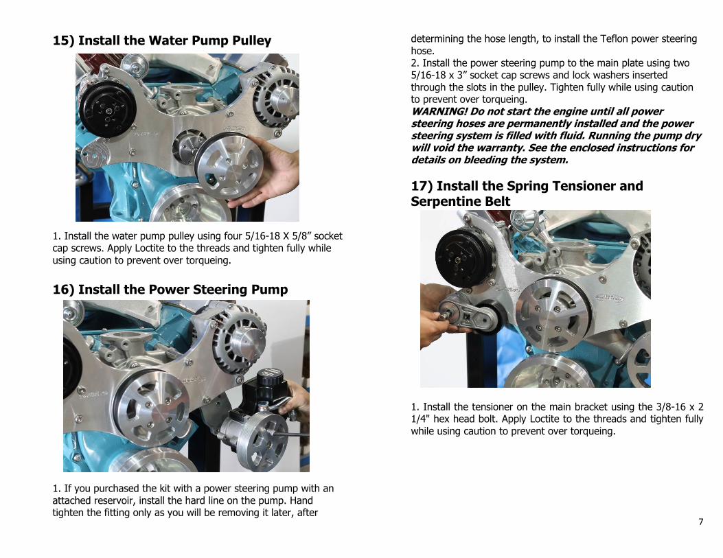
17) Install the Spring Tensioner and Serpentine Belt
1. Install the tensioner on the main bracket using the 3/8-16 x 2 1/4" hex head bolt. Apply Loctite to the threads and tighten fully while using caution to prevent over torqueing.

8
2. Route the belt onto the pulleys as shown. 3. Using a 1/2” drive ratchet, rotate the tensioner down and finish installing the belt. Slowly release the tensioner until it rests against the belt and tensions the system.
4. Install the aluminum tensioner cover using two 10-32 x 3/4" socket head flat head screws. Tighten fully while using caution to prevent over torqueing.
YOUR INSTALLATION IS COMPLETE!!
PLEASE THOROUGHLY READ ALL OF THE INTRUCTIONS FOR FILLING AND BLEEDING THE POWER STEERING SYSTEM AND FOR CHARGING THE AIR CONDITIONING BEFORE STARTING YOUR ENGINE. EDDIE MOTORSPORTS IS NOT RESPONSIBLE FOR CUSTOMER APPLICATIONS THAT ARE OUTSIDE THE NORMAL INTENDED USE OF OUR PRODUCTS, INCLUDING SPECIFIC MODEL AND YEAR APPLICATIONS, ENGINES EQUIPPED WITH SUPER CHARGERS, AND LATE MODEL EMISSIONS EQUIPPED VEHICLES.
FOR ANY QUESTIONS PLEASE CALL: 888-813-1293
PLEASE READ! IMPORTANT INFORMATION ABOUT YOUR AC COMPRESSOR
All charging procedures should be performed by a licensed and certified
technician. Installer and technicians should read this sheet and all
component instructions carefully before starting work. Please call if you
have any technical questions before, during or after the installation. Our
knowledgeable staff will be glad to assist you with any of your questions.

9
WARNING: Do not connect power to the AC clutch wire without first
connecting hoses and charging the system. Serious damage to your
compressor can occur and the warranty will be voided.
The Sanden A/C compressor supplied with your Eddie Motorsports S-
Drive kit is pre-filled with oil and Nitrogen charged from the factory to
insure proper lubrication of the internals during storage and transport.
Do not remove the block off plate on top of the compressor until you are
ready to install the hoses and charge the system.
Refrigerant
The Sanden A/C compressor supplied with your Eddie Motorsports S-
Drive kit is compatible with 134a refrigerant which is commonly used in
late model and aftermarket A/C systems. All part warranties are voided if
any refrigerant other than R134a is used. If your car is equipped with its
original A/C system and components, it will be necessary to convert your
system to use 134a. Consult a reputable A/C system manufacturer for
details on this conversion. We recommend the factory air experts at
Classic Auto Air 877-342-5526 www.classicautoair.com
System Charging Tips & Warnings PLEASE READ CAREFULLY
BEFORE CHARGING YOUR A/C!
1. Please keep in mind that regardless of you or your technician’s
experience, the charging processes for your Sanden pump will vary
greatly from stock OEM systems. Failure to follow these steps and proper
charging procedures will result in an improper installation or damaged
item and WILL VOID YOUR WARRANTY!
2. DO NOT ADD OIL! All new Sanden compressors contain a full
system charge of oil.
3. Before charging the system and putting power to the compressor, it is
necessary to clear the oil from the compressor head. With the belt
removed and the lines hooked up, manually turn the compressor clutch
hub (not the pulley) a minimum of 10 complete revolutions to clear the
oil.
4. DO NOT CHARGE THE SYSTEM IN LIQUID FORM. Unlike later
model vehicles, doing so will direct liquid refrigerant into the compressor
piston chamber, causing damage to the compressor reed valves and/or
pistons, as well as potentially seizing the compressor. Doing so voids all
warranty claims.
5. USE A CHARGING STATION TO EVACUATE AND CHARGE YOUR
SYSTEM
DO NOT TILT, SHAKE OR TURN REFRIGERANT CAN UPSIDE
DOWN DURING THE CHARGING PROCESS WHILE THE ENGINE
IS RUNNING! Evacuate the system for a minimum of 45 minutes
before charging. Longer if possible. When using a charging station,
meter the refrigerant into the system with the vehicle turned off. Then
allow a minimum of 30 minutes for liquid to “boil off,” or hand turn the
compressor hub (not the pulley) a minimum of 10 complete revolutions
to clear liquid refrigerant from the compressor piston chamber.
6. DO NOT CHARGE THE SYSTEM THROUGH THE HIGH
(DISCHARGE) SIDE OF THE SYSTEM! Refrigerant should be
administered through the low (Suction) side of the system.
Warranty All compressors carry a 1-year limited warranty. I
IMPORTANT INFORMATION ABOUT YOUR POWER STEERING
PUMP
Follow these procedures to ensure that the power steering system is
filled and purged correctly.
Prior to starting the car, fill the pump reservoir with power steering fluid.
Use fluid designed for use in power steering; brake or hydraulic fluid is
not an acceptable substitute.
With your car in “park”, the emergency brake engaged, and the engine
running, SLOWLY turn the steering wheel all the way to the right and
then all the way to the left. With the help of a second person and using
a long transmission funnel to insure that you are safely clear of moving
parts, simultaneously pour power steering fluid into the reservoir while
continuing to cycle the steering wheel. Do this until the reservoir is
properly filled and the fluid level remains constant. Fully tighten the cap
on the reservoir.
Eddie Motorsports
11479 Sixth St ● Rancho Cucamonga, CA 91730
888-813-1293 ph ● 909-945-9293 fax
www.eddiemotorsports.com

For Gear Box ApplicationsPower Steering Hose Diagram• When using a Remote Reservoir make sure that the power steering reservoir is mounted
so that the �ttings in the bottom of the tank are higher than the power steering pump.• Billet Aluminum attached Steering Reservoirs are not recommended foruse in high usage or high performance applications or with Hydroboost systems. These reservoirs should be used in conjunction with a high quality power steering �uid cooler.• Identify the pressure and return ports on your steering box, install the �ttings, and connect the power steering lines.• In most cases, the port on the gear box that is the tallest and farthest from the �rewall isthe high pressure line and the port closest to the �rewall is the low pressure return line. Often, there are arrows cast into the valve body to show the �uid direction. But this is not always the case. NOTE: It is the installer’s responsibility to make sure that the hose connections are correct! CONNECTING LINES TO THE INCORRECT PORT CAN DAMAGE YOUR STEERING BOX OR RACK! • Hoses must not touch any other part of the vehicle. Steering system noise could be caused by the hose touching the frame, body, or engine.• Make sure all hose connections are tight. Loose connections could leak and could allowair into the system. Do not over tighten O-ring �ttings as the O-ring could be damaged.• Do not start your engine until the system is �lled with �uid and fully bled. Doing so may cause damage to the power steering pump components.• For proper operation, read and follow the Eddie Motorsports power steering bleedinginstructions THOROUGHLY AND COMPLETELY before beginning your installation.
Return Line To Pump(-10 AN)
Pressure Line(-6 AN)
Return Line (-6 AN)To Tank
PressureValve
RemoteReservoir
Return Line(-8 AN)
Pressure Line(-6 AN)
MS100-03LHardline
(Included in EMS Pulley Kit)
PressureValve
Billet AttachedReservoir
Hose Clamp& Cover
PressureValve
-7 ANBraided Line
Pressure Line(-6 AN)
MS100-03LHardline
(Included in EMSPulley Kit)
PS Pump w/Plastic Reservoir
Plastic AttachedReservoir
3/8” Rubber Hose
Return

• When using a Remote Reservoir make sure that the power steering reservoir is mountedso that the �ttings in the bottom of the tank are higher than the power steering pump.• Billet Aluminum attached Steering Reservoirs are not recommended foruse in high usage or high performance applications or with Hydroboost systems. These reservoirs should be used in conjunction with a high quality power steering �uid cooler.• Identify the pressure and return ports on your rack and pinion, install the �ttings, and connect the power steering lines.• In most cases, the port on the rack and pinion that is higher/closer to the steering shaftis the return line and the port lower/closer to the rack is usually the pressure line. Oftenthere is a “P” cast into the body of the rack that con�rms the pressure port. But this is not always the case. NOTE: It is the installer’s responsibility to make sure that the hose connections are correct! CONNECTING LINES TO THE INCORRECT PORT CAN DAMAGE YOUR STEERING BOX OR RACK! • Hoses must not touch any other part of the vehicle. Steering system noise could be caused by the hose touching the frame, body, or engine.• Make sure all hose connections are tight. Loose connections could leak and could allowair into the system. Do not over tighten O-ring �ttings as the O-ring could be damaged.• Do not start your engine until the system is �lled with �uid and fully bled. Doing so may cause damage to the power steering pump components.• For proper operation, read and follow the Eddie Motorsports power steering bleedinginstructions THOROUGHLY AND COMPLETELY before beginning your installation.
For Rack & Pinion ApplicationsPower Steering Hose Diagram
RemoteReservoir
Return LineTo Pump(-10 AN)
Pressure Line(-6 AN)
Return Line (-6 AN)To Tank
PressureValve
Billet AttachedReservoir
Return Line(-8 AN)
Pressure Line(-6 AN)
MS100-03LHardline
(Included in EMS Pulley Kit)
PressureValve
Plastic AttachedReservoir
Hose Clamp& Cover
PressureValve
Pressure Line(-6 AN)
MS100-03LHardline
(Included in EMSPulley Kit)
PS Pump w/Plastic Reservoir
-7 ANBraided Line
3/8” Rubber Hose
Return