Bedienungsanleitung ST49 EN - PSG last parameter of the respective submenu (e.g. C99, b99...)...
32
PSG Petro Service GmbH & Co. KG, Tel.: +49 (0) 6171 / 9750-0, FAX: -30, Email: [email protected] Operation Manual Temperature Controller ST49 Revision 1.1, dated on 31.03.2008
Transcript of Bedienungsanleitung ST49 EN - PSG last parameter of the respective submenu (e.g. C99, b99...)...

PSG Petro Service GmbH & Co. KG, Tel.: +49 (0) 6171 / 9750-0, FAX: -30, Email: [email protected]
Operation Manual
Temperature Controller ST49
Revision 1.1, dated on 31.03.2008


PSG Petro Service GmbH & Co. KG, Tel.: +49 (0) 6171 / 9750-0, FAX: -30, Email: [email protected]
Page 3 of 32
Contents 1. User Consideration...........................................................................................................4 2. Product description and application..................................................................................5 3. Controller architecture ......................................................................................................5 4. Operation buttons and signal lamps.................................................................................6
Operation buttons ............................................................................................................6 Signal lamps....................................................................................................................6
5. Configuration ....................................................................................................................7
Menu level .......................................................................................................................7 Adjustment of control parameters....................................................................................7 Parameter setting of the control setpoint.........................................................................8 Parameter tables and explanations .................................................................................9 Configuration for electrical heated sample filter unit PFE, sample tube and sleeve .................................23
6. Status indications and error messages ..........................................................................23 7. Solid State Relay SSR (optional)....................................................................................24 8. Wiring diagram ...............................................................................................................26 9. Technical data ................................................................................................................27 10. Dimensions.....................................................................................................................29 11. Software .........................................................................................................................30

PSG Petro Service GmbH & Co. KG, Tel.: +49 (0) 6171 / 9750-0, FAX: -30, Email: [email protected]
Page 4 of 32
1. User Consideration Explanation of used symbols:
Particularly important information
Warning notice
Notice: This controller is designed only for industrial purposes. Read this operation manual carefully and completely. Start the installation and start-up afterwards. Only qualified personal who throughly understand the operation of this equipment should install and start-up this equipment. Never work on any control equipment without first removing all power supplies from the equipment. Non-compliance with this warning may result in serious personal injury and/or equipment damage. Consider the max. switching load of the controller and the SSR (Solid-State-Relay) respectively (see technical data on page 27). Depending on the heating power the max. length of a controlled electrical heated tube bundle / sample line is limited. You shall not be entitled to duplicate this document or in respect of any content (wholly or partly) to pass it on to third parties unless and to the extent expressly permitted. Although every effort has been taken to ensure the accuracy of this document, it may be necessary without notice to make amendments or correct omissions. PSG Petro Service GmbH & Co. KG (further “PSG”) cannot accept responsibility for damage, injury, or expenses resulting from the preceding advices and warnings.

PSG Petro Service GmbH & Co. KG, Tel.: +49 (0) 6171 / 9750-0, FAX: -30, Email: [email protected]
Page 5 of 32
2. Product description and application This micro-processed controller serves for temperature control of PSG electrical heated tube bundles / sample lines, sample filter units, sample tubes and sleeves. Beside resistance sensors and semiconductor thermo element the multi-sensor input can equally process 0...10 V and/or 4...20 mA. The PID and/or thermostat controlling can be activated by parameter setting. There are different outputs available, such as two relay contacts, a voltage output for SSR and an analogue output. Red LED lamps indicate the status of the output relays. The setpoints and parameters determining the process are adjusted by a 4-field plastic foil keyboard.
3. Controller architecture All outputs can be allocated with a special controller function by different parameters (H41…H44). Each controller unit is configurated by the accordant parameters.
Block diagram of the controller architecture / allocation of the outputs and control circuits (factory setting)

PSG Petro Service GmbH & Co. KG, Tel.: +49 (0) 6171 / 9750-0, FAX: -30, Email: [email protected]
Page 6 of 32
The controller is preset (factory setting) for PSG electrical heated tube bundles / sample lines (see parameter table on page 9 et seqq.). In case of an upper / lower temperature alarm or a sensor failure (see parameter C9, C29, C49 and C87) the controller output K1 switches to the alarm state. Setting of a temperature limiter alarm output K2 switches to the alarm state and the controlling is blocked as long as the correct keyword is entered (see menu levels / parameter P-- on page 7). All parameters, which has to be changed controlling an electrical heated sample filter unit, sample tube or a sleeve, is listed on page 23.
4. Operation buttons and signal lamps
Operation buttons
Key-Up Pushing this key you can increase the parameter or parameter value or scroll the parameter list. Key-Down Pushing this key you can decrease the parameter or parameter value or scroll the parameter list. In case of an alarm the buzzer function can be switched off with this key. Standby key (function key 1) Switching the controller on or off. After interruption of the power supply, parameter H17 is automatically set. Key SET Displaying setpoints and parameters. In combination with the Key-Up or Key-Down the values of setpoints and parameters are adjustable.
Signal lamps Lamp 1: Switch state output K1 (alarm relay, parameter H41) Lamp 2: Switch state output K2 (limiter, parameter H42) Lamp 3: Switch state output S3 (PID heating, voltage for SSR-device)

PSG Petro Service GmbH & Co. KG, Tel.: +49 (0) 6171 / 9750-0, FAX: -30, Email: [email protected]
Page 7 of 32
5. Configuration
Menu level Pushing the UP and DOWN key simultanious for at least 4 seconds, the controller changes to the menu level. It consists of several submenus listed by the respective initial letter followed by 2 hyphen (e.g. C -- for the C-level). Also parameter P-- for unlocking the controller is part of this level.
Parameter Untermenü Funktion P-- - Enter keyword -19 (negative value) C-- Controller level Application parameters b-- Intermediate level Connecting parameters H-- Hardware level Hardware parameters d-- Defrost level Defrosting parameters (control circuit 1) A-- Analogue level Parameter for analogue in- and outputs
Adjustment of control parameters The selection of the submenu occurs by scrolling with the UP and DOWN key. Pushing the SET-key the keyword of the selected level is requested. The keyword must be set by additionally pushing the UP or DOWN key (standard value: 0).
The last parameter of the respective submenu (e.g. C99, b99...) corresponds to the current keyword of this level and can be changed there.

PSG Petro Service GmbH & Co. KG, Tel.: +49 (0) 6171 / 9750-0, FAX: -30, Email: [email protected]
Page 8 of 32
Loosing the keyword the controller has to be send to PSG for unlocking. Entering the correct keyword the controller enters to the submenu and the display shows the first listed parameter after releasing the SET key. Pushing the SET key, the value of the selected parameter is indicated. Additionally pushing the UP or DOWN key, the value can be set. Releasing all keys, the new value is saved. If UP and DOWN keys are pushed simultaneous again for at least 4 seconds, the controller enters to the submenu again. Upon repeated pushing for 4 seconds or no pushing of any key for more than 60 seconds, the controller outputs the submenu back to the initial state.
Parameter setting of the control setpoint The control setpoint C1 is accessible directly with the SET key. Pushing also the UP or DOWN key it can be set.
Parameter Function Adjustment range Factory setting
C1 Control setpoint 1 for control circuit 1 and/or PID-regulation C10...C11 180°C
C2 Control setpoint 2 for control circuit 1 (*) C10...C11 0,0°C
* The activation of the second setpoint of circuit 1 C2 is indicated by a flashing LED on the right side
of the display. It can either be activated by the gate input or by the function key 1 (depending on parameter).

PSG Petro Service GmbH & Co. KG, Tel.: +49 (0) 6171 / 9750-0, FAX: -30, Email: [email protected]
Page 9 of 32
Parameter tables and explanations C-level (Controller) This level contains the application parameters. Thermostat 1
Parameter Function Adjustment range Factory setting
C1 Setpoint control circuit 1 -99...999°C 180°C C2 Setpoint control circuit 1 (*) -99,0...99,0°K 0,0°C C3 Offset for C1/C2 -99,0...99,0°K 0,0°K
C4 Function of control circuit 1 0: heating function 1: cooling function 1
C5 Hysteresis control circuit 1 0,1...99,9°K 1,0°K
C6 Hysteresis mode control circuit 1
0: symmetrical 1: one-sided 0
C7 Minimum action time control circuit 1"ON" 0...400 sec. 0 sec.
C8 Minimum action time control circuit 1"OFF" 0...400 sec. 0 sec.
C9 Function control circuit 1 at sensor failure
0: relay off 1: relay on 0
C10 Control range limitation, minimum Setpoint 1 -99,0°C...C11 -99,0°C
C11 Control range limitation, maximum Setpoint 1 C10...999,0°C 999,0°C
* The activation of the second setpoint of circuit 1 C2 is indicated by a flashing LED on the right side
of the display. It can either be activated by the gate input or by the function key 1 (depending on parameter).
Thermostat 2
Parameter Function Adjustment range Factory setting
C21 Setpoint control circuit 2 (b1=0) -99...999°C 0°C C22 Limiter value -99...999°C 192°C C23 Delta W2 (b1=1) -99...99°K 8°K
C24 Function of control circuit 2 0: heating function 1: cooling function 1
C25 Hysteresis control circuit 2 0,1...99,9°K 1°K
C26 Hysteresis mode control circuit 2
0: symmetrical 1: one-sided 0
C27 Minimum action time control circuit 2 "ON" 0...400 sec. 0 sec.
C28 Minimum action time control circuit 2 "OFF"" 0...400 sec. 0 sec.
C29 Function control circuit 2 at sensor failure
0: relay off 1: relay on 0

PSG Petro Service GmbH & Co. KG, Tel.: +49 (0) 6171 / 9750-0, FAX: -30, Email: [email protected]
Page 10 of 32
Thermostat 3
Parameter Function Adjustment range Factory setting
C41 Setpoint control circuit 3 (b2=0) -99...999°C 0,0°C
C43 Delta W3 (b2=1) -99,0...99,0°K 0,0°K
C44 Function of control circuit 3 0: heating function 1: cooling function 0
C45 Hysteresis control circuit 3 0,1...99,9°K 1,0°K
C46 Hysteresis mode control circuit 3
0: symmetrical 1: one-sided 0
C47 Minimum action time control circuit 3 "ON" 0...400 sec. 0 sec.
C48 Minimum action time control circuit 3 "OFF"" 0...400 sec. 0 sec.
C49 Function control circuit 3 at sensor failure
0: relay off 1: relay on 0
Alarm circuit
Parameter Function Adjustment range Factory setting
C61 Lower alarm value -99,0...C62 -99,0: inactive -20,0
C62 Upper alarm value C61...999,0 8,0
C63 Alarm functions
0: Boundary alarm, relative boundaries 1: Boundary alarm, absolute bundaries 2: Range alarm, relative boundaries 3: Range alarm, absolute boundaries 4: Boundary alarm, relative boundaries, alarm invers 5: Boundary alarm, absolute boundaries, alarm invers 6: Range alarm, relative boundaries, alarm invers 7: Range alarm, absolute boundaries, alarm invers
4
C64 Special function at limit alarm
0: not active 1: flashing display 2: buzzer 3: buzzer + flashing display 4: like 3, buzzer can be cancelled 5: like 4, restarts after 10 min. 6: like 4, restarts after 30 min.
4
C65 Hysteresis alarm circuit 0,1...99,9°K 1°K

PSG Petro Service GmbH & Co. KG, Tel.: +49 (0) 6171 / 9750-0, FAX: -30, Email: [email protected]
Page 11 of 32
PID-controller Setpoint of PID-controller is the setpoint of control circuit 1 (C1/C2)
Parameter Function Adjustment range Factory setting
C82 Proportional area at PID regulation 0,1…999,0°K 25°K
C83 Reset time at PID regulation (I-portion) 0...999 Sec., 0: inactive 200 sec.
C84 Lead time at PID regulation (D-portion) 0...999 Sec., 0: inactive 50 sec.
C85 Cycle time at PID regulation 2...100 sec. 15 sec. C86 Control variable dead volume 0,0..100,0 % 0,0 %
C87 Function PID control circuit at sensor failure -100,0 %...0…100,0 % 0,0 %
C88 PID-mode
0: PID 1: DiffPID (2 relays–heating, cooling) 2: PID with dead band at analogue output
0
C89 Cycle time motor valve (Differential PID) 2...100 sec. 8 sec.
C99 Keyword C-level -99…999 0 Parameter explanations C-level: C1: Setpoint of control circuit 1 (thermostat) This value corresponds with the setpoint set at the first control level. C2: Setpoint of control circuit 1 (thermostat) The activation of the 2nd setpoint C2 is indicated by a blinking LED on the right side of the display. The activation occurs either by the gate input or by the function key 1. In case of an activated 2nd setpoint by input E1 or function key 1 (depending on parameter), a recall of setpoint C2 is possible by pushing the SET-key. C3: Offset of C1/C2 This value will build the difference to the setpoint for control circuit 1, i.e. there is no regulation according to the preset value, but according to the sum of desired value and the value of C3. C4: Function of control circuit 1 The function of the relays, i.e. heating or cooling, is programmable independently. Heating means a disconnection of the power supply, if the temperature (actual value) reaches the setpoint. Cooling means a connection to the power supply, if the temperature (actual value) is higher than the setpoint.

PSG Petro Service GmbH & Co. KG, Tel.: +49 (0) 6171 / 9750-0, FAX: -30, Email: [email protected]
Page 12 of 32
C5: Hysteresis of control circuit 1 The hysteresis can be set symmetrically or one-sided at the desired value (see C6). At one-sided setting, the hysteresis works downward with heating contact and upward with cooling contact. At symmetrical hysteresis, half of the hysteresis value is effective below and half of the value above the switching point (see diagram 1 and 2).
Diagram 1: Heat controller, Diagram 2: Cool controller,
one-side hysteresis symmetrical hysteresis C6: Hysteresis mode of control circuit 1 This parameter set a symmetrically or one-sided hysteresis. At one-sided setting, the hysteresis works downward with heating contact and upward with cooling contact. At symmetrical hysteresis, half of the hysteresis value is effective below and half of the value above the switching point. C7/C8: Minimum action time of control circuit 1 "On"/"Off" These parameters permit a delay in switching on/off the relay in order to reduce the switching frequency. The adjusted time sets the entire minimum time period for a switching-on or switching- off phase. C9: Function of control circuit 1 at sensor failure In case of a sensor failure the selected relay (see H41, 42, 43) switches back to preset state. C10/C11: Control range limitation of setpoint 1”minimum”/”maximum” The adjustment range of the setpoint can be limited in both directions. Using this limitation, an operator of a system is not able to set unacceptable or dangerous setpoints. C21: Setpoint of control circuit 2 (thermostat) (b1=0) If parameter b1=1, this value is ineffective. C23: Value of deltaW2 (b1=1) In case of parameter b1=1, the setpoints for control circuit 1 and 2 are linked by a differential gap deltaW2 (C23). The following applies: Setpoint thermostat 2 = setpoint control circuit 1 (C1/C2) + deltaW2. This difference can be a positive or negative value, i.e. a leading or lagging contact can be realised. C24: Function of control circuit 2 The function of the relays, i.e. heating or cooling, is programmable independently. Heating means a disconnection of the power supply, if the temperature (actual value) reaches the setpoint. Cooling means a connection to the power supply, if the temperature (actual value) is higher than the setpoint.

PSG Petro Service GmbH & Co. KG, Tel.: +49 (0) 6171 / 9750-0, FAX: -30, Email: [email protected]
Page 13 of 32
C25: Hysteresis of control circuit 2 The hysteresis can be set symmetrically or one-sided at the desired value (see C26). At one-sided setting, the hysteresis works downward with heating contact and upward with cooling contact. At symmetrical hysteresis, half of the hysteresis value is effective below and half of the value above the switching point (see diagram 1 and 2). C26: Hysteresis mode of control circuit 2 This parameter set a symmetrically or one-sided hysteresis. At one-sided setting, the hysteresis works downward with heating contact and upward with cooling contact. At symmetrical hysteresis, half of the hysteresis value is effective below and half of the value above the switching point. C27/C28: Minimum action time of control circuit 2 "On"/"Off" These parameters permit a delay in switching on/off the relay in order to reduce the switching frequency. The adjusted time sets the entire minimum time period for a switching-on or switching- off phase. C29: Function of control circuit 2 at sensor failure In case of a sensor failure the selected relay (see H41, 42, 43) switches back to preset state. C41: Setpoint of thermostat 3 (b2=0) If parameter b2=1, this value is ineffective. C43: Value deltaW3 (b2=1) In case of parameter b2=1, the setpoints for control circuit 1 and 3 are linked by a differential gap deltaW2 (C43). The following applies: Setpoint thermostat 3 = setpoint control circuit 1 (C1/C2) + deltaW3. This difference can be a positive or negative value, i.e. a leading or lagging contact can be realised. C44: Function of control circuit 3 The function of the relays, i.e. heating or cooling, is programmable independently. Heating means a disconnection of the power supply, if the temperature (actual value) reaches the setpoint. Cooling means a connection to the power supply, if the temperature (actual value) is higher than the setpoint. C45: Hysteresis control of circuit 3 The hysteresis can be set symmetrically or one-sided at the desired value (see C46). At one-sided setting, the hysteresis works downward with heating contact and upward with cooling contact. At symmetrical hysteresis, half of the hysteresis value is effective below and half of the value above the switching point (see diagram 1 and 2). C46: Hysteresis mode of control circuit 3 This parameter set a symmetrically or one-sided hysteresis. At one-sided setting, the hysteresis works downward with heating contact and upward with cooling contact. At symmetrical hysteresis, half of the hysteresis value is effective below and half of the value above the switching point. C47/C48: Minimum action time of control circuit 3 "On"/”Off” These parameters permit a delay in switching on/off the relay in order to reduce the switching frequency. The adjusted time sets the entire minimum time period for a switching-on or switching- off phase. C49: Function of control circuit 3 at sensor failure In case of a sensor failure the selected relay (see H41, 42, 43) switches back to preset state.

PSG Petro Service GmbH & Co. KG, Tel.: +49 (0) 6171 / 9750-0, FAX: -30, Email: [email protected]
Page 14 of 32
C61: Lower alarm value C62: Upper alarm value The alarm output is a boundary alarm or a range alarm with one-sided hysteresis (see parameter C65). The limits of the boundary alarm as well as the range alarm can be relative, i.e. running with a changing setpoint C1/C2 or absolute, i.e. independent of the setpoint C1/C2. The hysteresis is one-sided. In case of the boundary alarm inside the limits, in case of the range alarm outside the limits (see diagram 3-6). Presetting parameter C61=-99,0 the lower limit is not effective.
C63: Function alarm output The alarm evaluates an upper and lower limit value (see parameters C61 and C62). Parameter activates the alarm either if the temperature is inside the limits or outside the limits. In case of sensor failure, the alarm will be activated independently of this adjustment. The output is also invertible, in order to work as a disengaging (see diagram 3 – 6). C64: Special function at limit alarm In case of an active alarm a blinking display and/or a buzzer is selectable by this parameter. A sensor failure (display F1L or F1H) will be indicated by a blinking display and the buzzer independently of the preset of this parameter.
Diagram 5: Boundary alarm, alarm contact inverse C63=4 limits relative C63=5 limits relative
Diagram 6: Range alarm, alarm contakt inverse C63=6 limits relative C63=7 limits relative
Diagram 3: Boundary alarm, alarm contact normal C63=0 limits relative C63=1 limits absolute
Diagram 4: Range alarm, alarm contact normal C63=2 limits relative C63=3 limits relative

PSG Petro Service GmbH & Co. KG, Tel.: +49 (0) 6171 / 9750-0, FAX: -30, Email: [email protected]
Page 15 of 32
C65: Hysteresis alarm circuit The hysteresis is set one-sided to the preset limit value. It is effectively depending on alarm definitions (see diagram 3 - 6). C82: Proportional range of PID controlling When the actual value reaches the setpoint, the proportional term reduces the regulating variable +/-100 % to 0 %. C83: Integral time of PID controlling (integral term) C84: Deviation action time of PID controlling (differential term) A simple proportional controller can’t work without a deviation of the actual value and the setpoint. The integral term compensates this control deviation completely. The integral time is that time, the compensation of a remaining temperature deviation about the value of the proportional term takes. A short integral time means a fast re-adjust. If the integral time is too short, the system is inclined to oscillate. The differential term is damping the temperature deviation. A long deviation action time means a strong damping effect. If the deviation time is too long, the system is inclined to oscillate. If zero (0) is preset, the parameters are not effective, so a PI or PD controlling can be realized. C85: Cycle time of PID controlling The cycle time is that time, the control output completes one switch period, i.e. switching off and on each one time. The shorter the cycle time the faster the controlling. But take note that a shorter cycle time results in a higher switch frequency of the output and will lead in a faster abrasion of the relay. For very fast closed loop controlled systems with high switch frequencies the voltage output is recommended. C86: Regulating variable “dead band”
With parameter C86 the value of the dead band of the PID regulating variable can be set in percent (%). Usually this takes place using a clocked PID controller (relay) to realize a minimum turn-on time. Setting parameter C88=1 (differential PID) a pseudo hysteresis can be realized. This will lead to a reduction of the switch frequency, if the actual value ≈ setpoint. Setting parameter C88=2 the dead band will be also available at analogue output (see sketch).
C87: Function of PID control circuit in case of a sensor failure In the case of a sensor failure, the PID regulating variable changes to the preset state.
PSG Petro Service GmbH & Co. KG, Tel.: +49 (0) 6171 / 9750-0, FAX: -30, Email: [email protected]
Page 16 of 32
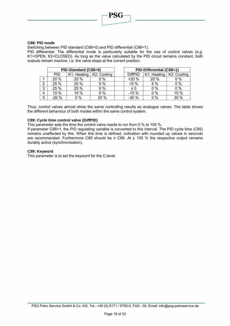
C88: PID mode Switching between PID standard (C88=0) and PID differential (C88=1). PID differential: The differential mode is particularly suitable for the use of control valves (e.g. K1=OPEN, K2=CLOSED). As long as the value calculated by the PID circuit remains constant, both outputs remain inactive, i.e. the valve stops at the current position.
PID-Standard (C88=0) PID-Differential (C88=1) PID K1: Heating K2: Cooling DiffPID K1: Heating K2: Cooling
1 20 % 20 % 0 % +20 % 20 % 0 % 2 25 % 25 % 0 % +5 % 5 % 0 % 3 25 % 25 % 0 % ± 0 0 % 0 % 4 10 % 10 % 0 % -15 % 0 % 15 % 5 -20 % 0 % 20 % -30 % 0 % 30 %
Thus, control valves almost show the same controlling results as analogue valves. The table shows the different behaviour of both modes within the same control system. C89: Cycle time control valve (DiffPID) This parameter sets the time the control valve needs to run from 0 % to 100 %. If parameter C88=1, the PID regulating variable is converted to this interval. The PID cycle time (C85) remains unaffected by this. When this time is defined, indication with rounded up values in seconds are recommended. Furthermore C85 should be ≥ C89. At ± 100 % the respective output remains durably active (synchronisation). C99: Keyword This parameter is to set the keyword for the C-level.

PSG Petro Service GmbH & Co. KG, Tel.: +49 (0) 6171 / 9750-0, FAX: -30, Email: [email protected]
Page 17 of 32
b-level (between) This level contains the parameters for different combinations.
Parameter Function Adjustment range Factory setting
b1 Activation setpoint combination for 0: no combination 1
b2 Activation setpoint combination for thermostat 1 and 3 (deltaW3)
0: no combination 1: setpoint thermostat 3 = C1/C2 + C43
0
b11 Delay control circuit 1, 2, 3 after "Power-On" 0...400 sec. 0 sec.
b12 Mutual delay control circuit 1, 2, 3 0...400 sec. 0 sec.
b13 Alarm suppression after "Power-On", "setpoint" 0...250 min. 45 min.
b21 Linkage analogue output 0: PID regulating variable 1: actual value 2: setpoint
0
b99 Keyword b-level -99..999 0 Parameter explanations b-level: b1: Activation setpoint linking of thermostat 1 and thermostat 2 (deltaW2) This parameter determines whether the setpoints for thermostat 1 and 2 independently adjustable (parameter C21) or whether they are tied with one another by a switching offset deltaW2 (parameter C23). b2: Activation setpoint linking of thermostat 1 and thermostat 3 (deltaW3) This parameter determines whether the setpoints for thermostat 1 and 3 independently adjustable (parameter C41) or whether they are tied with one another by a switching offset deltaW2 (parameter C43). b11: Delay of control circuit 1, 2, 3 after "Power-On" This parameter allows a switching-on delay of relays after switching-on the power supply. This delay corresponds with the time set here. b12: Mutual delay of control circuit 1, 2, 3 This parameter makes a mutual switching-on delay of relays possible, depending on whichever contact is switched first. b13: Alarm suppression after "Power-On", "setpoint" This parameter allows a switching-on delay of the alarm contact after switching on the power supply. This delay corresponds with the time set here. A change of this value will be effective after a reset (switching off and on the power supply). b21: Function of the analogue output This is to specify whether the analogue output carries the variable (PID), the actual value or the setpoint. The allocation of the output voltage (max. 0...10 V) in correspondence with the indicated value is effected by parameters A51 and A52. Output of voltages is always positive only. b99: Keyword This parameter is to set the keyword for the b-level.

PSG Petro Service GmbH & Co. KG, Tel.: +49 (0) 6171 / 9750-0, FAX: -30, Email: [email protected]
Page 18 of 32
H-level (hardware) This level contains the hardware parameters.
Parameter Function Adjustment range Factory setting
H1 Key lock 0: no key lock 1: key lock 0
H11 Indication mode display 1 0: integrals 1: decimals in 0.5°K 2: decimals in 0.1°K
2
H12 Display 1 mode 1: actual value 2: setpoint 3: PID variable
1
H13 Indication mode display 2 N/A 2 H14 Display 2 mode N/A 2 H15 Temperature scale 0: Celsius 1: Fahrenheit 0
H16 Indication standby
0: display deactivated (point to the right) 1: AUS 2: OFF
1
H17 Mode following "Power-On" “ 0: Off 1: On 2: Auto
1
H31 Assigning function key 1
0: no function 1: standby key 2: setpoint 1 / setpoint 2 3: upper temp. alarm value
3
H35 Activation of key acknowledgement
0: no key acknowledgement 1: key acknowledgement with buzzer
0
H40 Inversion of LED´s 3: not inverted 3
H41 Function output K1
0: no connection 1: thermostat 1 2: thermostat 2 3: thermostat 3 4: alarm function 5: PID-mode heating 6: PID-mode cooling 7: Limiter
4
H42 Function output K2 see H41 7 H43 Function output S3 see H41 5 H44 Not used 0
H51 Mains frequency 0: 50 Hz 1: 60 Hz 0
H99 Keyword H-level -99…999 0 Parameter explanations H-level: H1: Key lock The key lock allows a blocking of the control keys. In locked condition the adjustment of parameters by keys is not possible. At the attempt to set the parameters despite key lock the message "===" appears in the display.

PSG Petro Service GmbH & Co. KG, Tel.: +49 (0) 6171 / 9750-0, FAX: -30, Email: [email protected]
Page 19 of 32
H11: Indication mode display 1 The value can be indicated in integrals or with decimals in 0,5°K or 0,1°K. At indication in 0,5°K the value is rounded up or down. In general, all parameter indications are presented in 0,1°K. H12: Display 1 mode Parameter H12=1 indicates the actual value, parameter H12=2 indicates the setpoint C1 or C2 and parameter H12=3 statically indicates the PID regulating variable in the display. Therefore, the current actual value can only be indicated with parameter A01. H13: Indicator mode display 2 Not evaluated H14: Display 2 mode Not evaluated H15: Temperature scale Indication can be switched between Fahrenheit and Celsius. At conversion, the parameters and setpoints maintain their numerical value and adjustment range. (Example: A controller with the setpoint of 0°C is switched to Fahrenheit. The new setpoint is then interpreted as 0°F, which corresponds to a temperature of -18°C). Indication limits with °F can be smaller than the actual measuring range! H16: Indication standby In standby mode the here set value appears in the display. H17: Mode following "Power-On" After switching on the mains voltage the controller automatically goes to the condition set here. Parameter H17=2 applies to the condition prior to the separation from the net. H31: Assigning function key 1 Setting parameter H31=0 deactivates the key, parameter H31=1 functions as standby key. H31=2 allows a change between setpoint 1 (C1) and setpoint 2 (C2) and with H31=3 the upper temperature alarm value (parameter C62) can be set directly. H35: Activation of key acknowledgement This parameter permits to switch the internal buzzer on/off by key confirmation. H40: Inversion of LED´s With this parameter the control of the LED´s can be inverted logically. The value is preset to H40=3 and is changeable only by the manufacturer. H41: Function output K1 H43: Function output K2 H44: Function output S3 H44: Function hybrid output K1 Generally, the outputs are exchangeable with parameter adjustments, in order to achieve an optimal relation of the existing hardware with regard to contact rating, kind of contact and cycle number. Therefore, these parameters first assign the outputs to the controller function. Activation of H44 deactivates H41 and H43. H51: Mains frequency This parameter is to select the mains frequency. H99: Keyword This parameter is to set the keyword for the H—level.

PSG Petro Service GmbH & Co. KG, Tel.: +49 (0) 6171 / 9750-0, FAX: -30, Email: [email protected]
Page 20 of 32
d-level (defrosting functions) This level contains the parameters for defrosting. Defrosting parameters are only effective for control circuit 1!
Parameter Function Adjustment range Factory setting
d0 Defrosting interval TH1 1...99h 0: no defrosting 0
d2 Defrosting temperature TH1 -99,0...999,0°C 10,0°C
d3 Defrosting time limit TH1 1…99 min. 0: no time limit 30 min.
d9 Manual defrosting TH1 0...1 0 d99 Keyword d-level -99...999 0
Parameter explanations d-level: d0: Defrosting interval The "defrosting interval" defines the time, after which a defrosting process is started. After each defrosting start, this time is reset and runs the next interval. Manual defrosting: Pushing the key UP for at least 3 sec. the defrosting interval is activated earlier. Alternatively parameter d9 can be applied for this function, too. The next automatic defrosting process takes place again after the time d0 (defrosting synchronisation). d2: Defrosting temperature This permits to terminate defrosting when the adjusted desired temperature value is reached. The defrosting time set with "d3" nevertheless runs at the same time, i.e. it functions as safety net to terminate the defrosting process in case the defrosting temperature is not reached. d3: Defrosting time limit After the here set time the defrosting process is terminated. d9: Defrosting time limit At change of 0 -> 1 the defrosting process is started and the defrosting interval is reset (defrosting synchronisation). d99: Keyword This parameter is to set the keyword for the d-level.
PSG Petro Service GmbH & Co. KG, Tel.: +49 (0) 6171 / 9750-0, FAX: -30, Email: [email protected]
Page 21 of 32
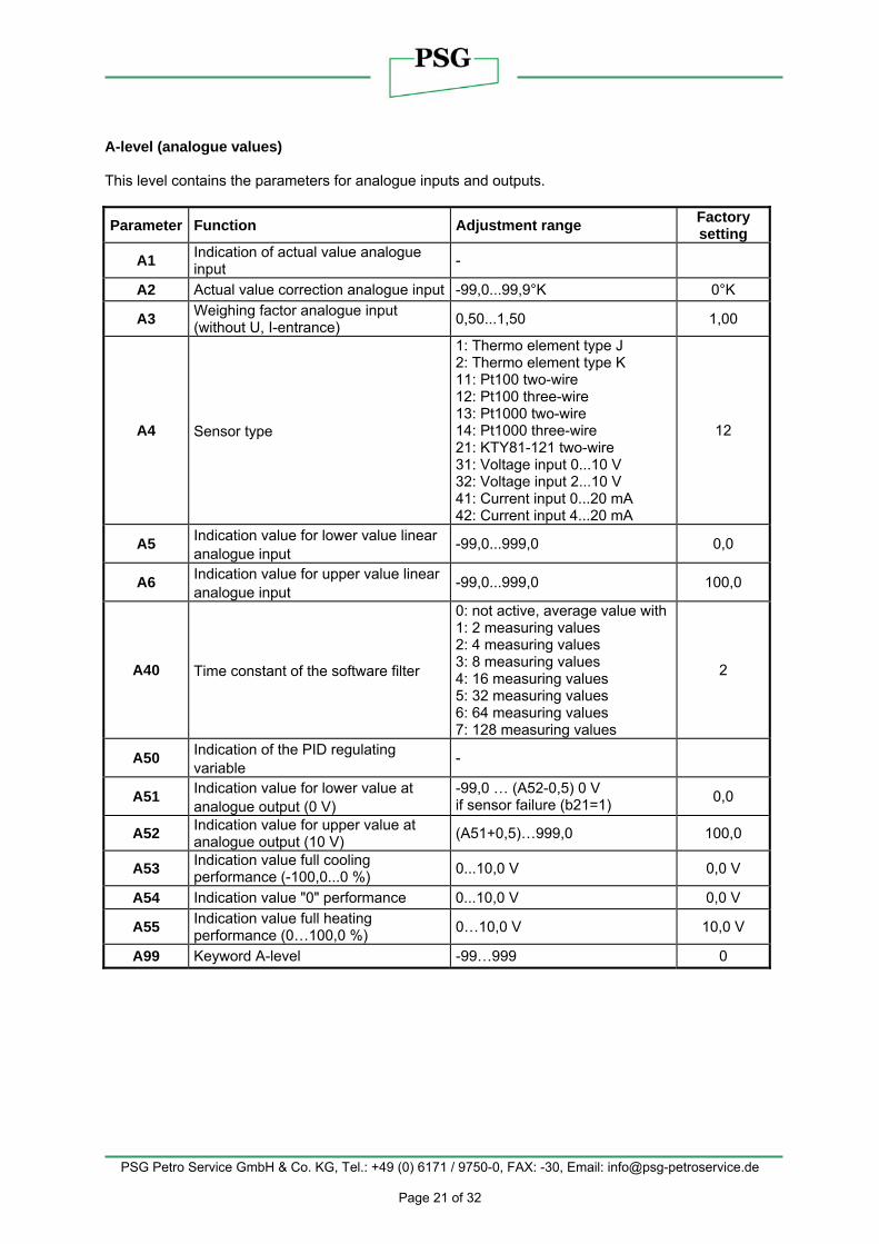
A-level (analogue values) This level contains the parameters for analogue inputs and outputs.
Parameter Function Adjustment range Factory setting
A1 Indication of actual value analogue input -
A2 Actual value correction analogue input -99,0...99,9°K 0°K
A3 Weighing factor analogue input (without U, I-entrance) 0,50...1,50 1,00
A4 Sensor type
1: Thermo element type J 2: Thermo element type K 11: Pt100 two-wire 12: Pt100 three-wire 13: Pt1000 two-wire 14: Pt1000 three-wire 21: KTY81-121 two-wire 31: Voltage input 0...10 V 32: Voltage input 2...10 V 41: Current input 0...20 mA 42: Current input 4...20 mA
12
A5 Indication value for lower value linear analogue input
-99,0...999,0 0,0
A6 Indication value for upper value linear analogue input
-99,0...999,0 100,0
A40 Time constant of the software filter
0: not active, average value with 1: 2 measuring values 2: 4 measuring values 3: 8 measuring values 4: 16 measuring values 5: 32 measuring values 6: 64 measuring values 7: 128 measuring values
2
A50 Indication of the PID regulating variable
-
A51 Indication value for lower value at analogue output (0 V)
-99,0 … (A52-0,5) 0 V if sensor failure (b21=1) 0,0
A52 Indication value for upper value at analogue output (10 V) (A51+0,5)…999,0 100,0
A53 Indication value full cooling performance (-100,0...0 %) 0...10,0 V 0,0 V
A54 Indication value "0" performance 0...10,0 V 0,0 V
A55 Indication value full heating performance (0…100,0 %) 0…10,0 V 10,0 V
A99 Keyword A-level -99…999 0

PSG Petro Service GmbH & Co. KG, Tel.: +49 (0) 6171 / 9750-0, FAX: -30, Email: [email protected]
Page 22 of 32
Parameter explanations d-level: A1: Indication of actual value analogue input The here indicted temperature value is the sum of the actual measured value of sensor F1 and the actual value correction according to parameter A2. A2: Actual value correction analogue input With this parameter it is possible to correct actual value deviations caused by sensor tolerances or extremely long sensor lines for example. The control measuring value is increased or decreased by the here set value. A3: Weighing factor analogue input (without U, I-entrance) With this parameter the actual value can be submitted to weighing. The measured value is multiplied by it and both indicated in the display and applied for regulation. A4: Analogue input type These parameters permit selection of the sensor type, respectively the type of analogue input if the needed hardware prerequisites are available. A5: Indication value for lower value linear analogue input A6: Indication value for upper value linear analogue input These parameters allow scaling of the linear analogue input. The value to be indicated for the lower and upper input value then defines the range the controller will indicate. A40: Time constant of the software filter With several measuring values, it is possible to obtain an average value. If a sensor with a very fast reaction to external influences is used, an average value ensures a calm signal process. A50: Indication of the PID regulating variable Indication of the internally computed PID regulating variable from -100 %... 10 %. A51: Indication value for lower value at analogue output (0 V) A52: Indication value for upper value at analogue output (10 V) Indication of the actual value (see b21) is subject to the following range adjustment: If the indication value reaches the value set in A51, voltage is 0 V. If the indication value reaches the value set in A52, voltage is 10 V. A53: Indication value full cooling performance (-100,0...0 %) A54: Indication value "0" performance A55: Indication value full heating performance (0...100,0 %) Indication of the actual value (see b21) is subject to the following range adjustment: If cooling is to be performed with 100 % cooling performance, voltage is as set in A53. If neither heating nor cooling is required, tension is as set in A54. If heating is to be performed with 100 % heating performance, voltage is as set in A55. A99: Keyword This parameter permits setting of the keyword for the A-level.

PSG Petro Service GmbH & Co. KG, Tel.: +49 (0) 6171 / 9750-0, FAX: -30, Email: [email protected]
Page 23 of 32
Configuration for electrical heated sample filter unit PFE, sample tube and sleeve
Parameter Sample filter unit PFE, uncoated
Sample filter unit PFE, coated Sample tube Heating sleeve
C1 210°C 190°C 180°C on request C22 222°C 212°C 192°C on request C23 12°K 22°K 12°K on request C82 12,3°K 22,2°K 25°K on request C83 923 sec. 987 sec. 200 sec. on request C84 231 sec. 247 sec. 50 sec. on request C85 62 sec. 37 sec. 15 sec. on request B13 100 min. 90 min. 45 min. on request
Heated tube bundles of type CGWB 13 and with the article numbers 50.03.xx.xx respectively must be heated at least for 40 hours. After this time the CO-concentration is < 0,2 ppm/m. Heated sample lines of the type TBL01 and with the article numbers 51.xx.xx.xx respectively must be heated at least for 5 hours. After this time the CO-concentration is < 0,08 ppm/m. Non-compliance may result in measurement errors and contaminations respectively.
6. Status indications and error messages
Message Reason Remedial action
F 1_ Sensor failure (H: open-circuit or L: short-circuit at sensor F1)
Check sensor
F 2_ Sensor failure (H: open-circuit or L: short-circuit at 3-wire correction)
Check sensor
E P_
0: Error program memory 1: Error parameter memory => ALL OUTSPUTS WILL BE SWITCHED OFF
Repair controller
--- Display overrun or key lock
Flashing Display
Temperature alarm at too high or too low temperature (if activated)
If an error is recognised in the parameter memory (indication EP) and therefore the saved settings cannot to be used, relays are set out of power supply.

PSG Petro Service GmbH & Co. KG, Tel.: +49 (0) 6171 / 9750-0, FAX: -30, Email: [email protected]
Page 24 of 32
7. Solid State Relay SSR (optional)
Short description The electronic load relay KR-... is based on a semiconductor. An alternating current is switched by two antiparallel thyristors. The electronic load relay has two galvanic isolated current circuits, a load circuit and a control circuit. Both antiparallel thyristors of the load circuit are triggered by the supply of the control voltage (12…30 V). The load circuit completes, i.e. they act as a “normally open” contact. An optical coupler with an integrated no-voltage switch is used. The completion and switch-off occurs while the alternating voltage passes the zero crossing. This way the interferences of the power supply are hold down. Installation Mounted on a metall plate or better on a DIN mounting rail the electronic load relay switches up to 6 A without additional heat sink. For the DIN mounting rail use the accordant supply. For applications > 6 A the relay must be mounted on a heat sink with adequate dimensions. Use the heat sink E2. For further informations see section “Cooling”. Start running the semiconductor relay after correct installation. The phase of the switching voltage is indicated by a glim lamp, as long as the voltage supplys the contact element of the relay and the contact element is not switching. Supplying the control voltage the electronic load relay switches the load circuit, indicated by the LED “control” instead of the glim lamp “power”. The fuse, used in the load circuit must fulfil the following conditions: The tripping characteristic of the safety parts must be under the limit current charactersitic of the protected parts (thyristor) during the whole operating time. Error detection a) If the load is connected to the SSR (clamp 2) and clamp 3 and 4 is not controlled, the glim lamp „power“ has to glow, assumed the phase of the switching voltage is applied to clamp 1 and a load is connected to the neutral terminal and clamp 2 (see drawing below). Otherways the semiconductor or the fuse is defect. b) If the controlling of clamp 3 and 4 is active (indicated by LED “control”) the glim lamp “power” must go out. Otherways the semiconductor is defect.

PSG Petro Service GmbH & Co. KG, Tel.: +49 (0) 6171 / 9750-0, FAX: -30, Email: [email protected]
Page 25 of 32
Cooling Mounting the heat sink take care that a maximum heat exchange is possible. If the air circulation is inhibited because of a cable channel or other parts an additional ventilation is nesessary. Operating with a no-voltage switch the heat sink is designed for the following permanent load: E2 = up to 25 A / 250 VAC Mounting The heat sink has two flutes holding nuts to mount the electronic load relay.

PSG Petro Service GmbH & Co. KG, Tel.: +49 (0) 6171 / 9750-0, FAX: -30, Email: [email protected]
Page 26 of 32
8. Wiring diagram

PSG Petro Service GmbH & Co. KG, Tel.: +49 (0) 6171 / 9750-0, FAX: -30, Email: [email protected]
Page 27 of 32
9. Technical data Measuring input F1: Temperature sensor, selection of the following types: Messuring range: Typ J: -99°C...+999°C (zero compensation 25,0°C)
Typ K: -99°C...+999°C (zero compensation 25,0°C) Pt100-2: -99°C...+550°C Pt100-3: -99°C...+500°C (max. 2x 20R cable resistance) Pt1000-2: -99°C...+400°C Pt1000-3: -99°C...+400°C (max. 2x 20R cable resistance) PTC: -50°C...+150°C U (0-10 V): -0,1 V...10,1 V U (2-10 V): 1,5 V...10,1 V I (0-20 mA): -0,1 mA…20,1 mA I (4-20 mA): 3,5 mA…20,1 mA
The measuring ranges are related to the controller and assume an appropriate sensor. Measuring accuracy of the measuring range: +/- 0,5 % The inputs for current or voltage can be adjusted to the measuring and display ranges by suitable parameters. Input impedance for current input (pin 13+ and Pin 14-): >10 kΩ Input impedance for voltage input (pin11+ and Pin 12-): ca. 31,6 Ω Outputs K1: Relay 8(1,5) A, 250 V~, normally-open contact, function see Parameter H41 K2: Relay 8(1,5) A, 250 V~, normally-open contact, function see Parameter H42 S3: Voltage for SSR, 0/12 V, max. 30 mA, function see Parameter H43 H1: (optional) Installed buzzer, ca. 85 dB. SSR: (optional) For technical data of the SSR see chapter 7, page 24 Continuous output S1: Linear voltage output 0...+10 V, for load min. 1 kΩ Display One 3-digit LED-Display, height 10 mm, colour red Three LEDs, diameter 3 mm, for status display of the outputs K1, K2, S3 Power supply 230 VAC +/-10 %, (50/60 Hz), power consumption max. 2,2 VA Connectors Screw terminals, 2x 8-pole, for cable up to 2,5 mm² Ambient conditions: Storage temperature: -20°C...+70°C Operating temperature: 0...55°C Relative humidity: max. 75%, without dew

PSG Petro Service GmbH & Co. KG, Tel.: +49 (0) 6171 / 9750-0, FAX: -30, Email: [email protected]
Page 28 of 32
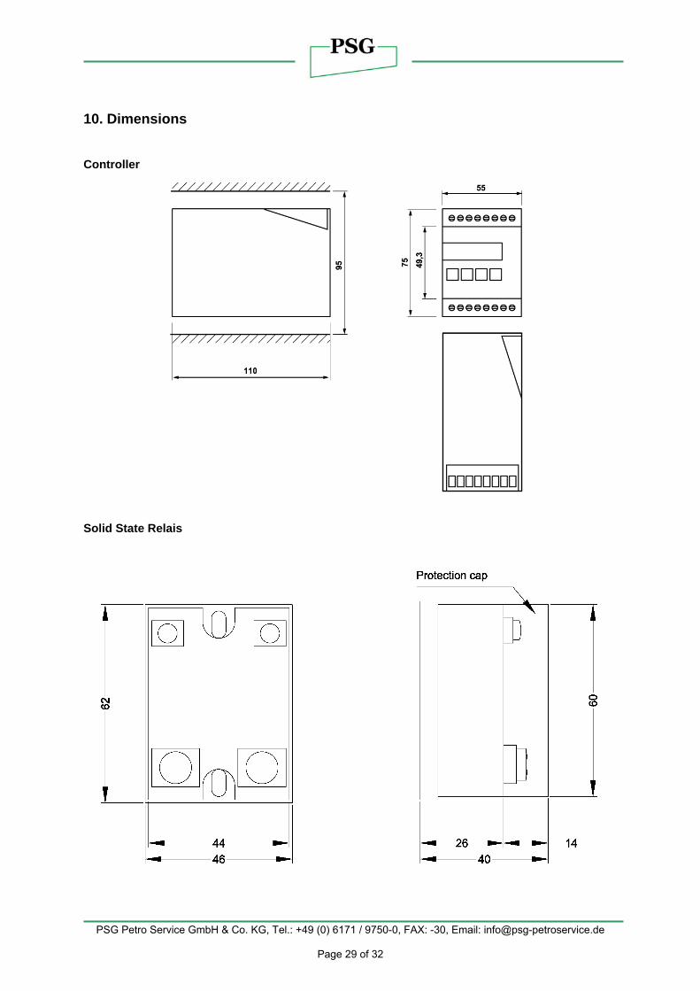
Weight ca. 360g, without sensor Enclosure IP00 Protection class Protection class II, isolated mounting Standards CE Low-Voltage Directive 73/23/EEC Safety requirements for electrical equipment for measurement, control and laboratory use EN 61010-1:2001 CE Electromagnetic compatibility 89/336/EEC, Level 3 Installation data Unit is to be installed on a DIN rail or directly mounted on a wall by screws. Rail installation: Max. width 34 mm Wall mounting: Max. screw diameter 4 mm Dimensions: 75 x 55 x 110 mm (HxWxD)
PSG Petro Service GmbH & Co. KG, Tel.: +49 (0) 6171 / 9750-0, FAX: -30, Email: [email protected]
Page 29 of 32
10. Dimensions Controller
Solid State Relais

PSG Petro Service GmbH & Co. KG, Tel.: +49 (0) 6171 / 9750-0, FAX: -30, Email: [email protected]
Page 30 of 32
Heat sink E2
11. Software The actual version of the software will be displayed by pushing the SET, UP and DOWN Key synchronous. Actual software version: .105

PSG Petro Service GmbH & Co. KG
Industriestr. 8a D-61449 Steinbach/Ts.
Tel.: +49 (0) 6171 / 9750-0
Fax: +49 (0) 6171 / 9750-30 Email: [email protected] Web: www.psg-petroservice.de


![Najdorf [B90 B99] - Time to get classyterrycucf.weebly.com/uploads/1/9/2/9/19295043/najdorf.pdf · Najdorf [B90−B99] Written by GM John Fedorowicz, GM Tony Kosten & IM Richard Palliser](https://static.fdocuments.us/doc/165x107/5a78de7e7f8b9a21538e8b3c/najdorf-b90-b99-time-to-get-b90b99-written-by-gm-john-fedorowicz-gm-tony.jpg)


![Molecular Dynamics of C99-Bound -Secretase Reveal Two ... · membrane-bound C99 is unavailable, and just recently was a structure published of the shorter C83 analog bound to γ-secretase[19].](https://static.fdocuments.us/doc/165x107/5f4dcbca465a9b47ae7bbe88/molecular-dynamics-of-c99-bound-secretase-reveal-two-membrane-bound-c99-is.jpg)