
Bedienungsanleitung NRT en Stand 10-04-2008
52
Transcript of Bedienungsanleitung NRT en Stand 10-04-2008
8/6/2019 Bedienungsanleitung NRT en Stand 10-04-2008
http://slidepdf.com/reader/full/bedienungsanleitung-nrt-en-stand-10-04-2008 1/52
8/6/2019 Bedienungsanleitung NRT en Stand 10-04-2008
http://slidepdf.com/reader/full/bedienungsanleitung-nrt-en-stand-10-04-2008 2/52
NRT Installation and Operating Manual
© Copyright 2008 Telegärtner Elektronik GmbH, Deutschland. All rights reserved. No part of this installation and operating manual may be reproduced without the prior written consent of Telegärtner Elektronik GmbH.
Please read the following safety information before beginning the installation.
IMPORTANT SAFETY INFORMATIONPLEASE KEEP THIS OPERATING MANUAL WITH THE APPLIANCE. Thismanual contains important instructions which you must follow duringinstallation or maintenance work. Please read all instructions carefully beforeyou start work, and keep this manual in a safe place so that you can use it for subsequent work.
8/6/2019 Bedienungsanleitung NRT en Stand 10-04-2008
http://slidepdf.com/reader/full/bedienungsanleitung-nrt-en-stand-10-04-2008 3/52
NRT Installation and Operating Manual 1
Table of Contens
Table of Contens.....................................................................................................1
General .................................................................................................................... 3
General Performance Features of the Emergency Calling System....................... 4 Additional Features of NRT 1 NT .......................................................................... 4 Additional Features of NRT 1 NT iS...................................................................... 4 Additional Features of NRT 2 NT .......................................................................... 5
Technical Data ........................................................................................................ 5
Mounting Location and Installation........................................................................7
First Voice Unit, Loud Speaker, Microphone.........................................................8
Installation Dimensions..........................................................................................9
NRT 1 NT / NRT 2 NT Plastic Casing, Electronics Box.........................................9 Voice Module / Microphone.................................................................................10 Bore Holes for Electronics Box............................................................................11
Description of NRT 1 NT Connectors..................................................................12
Description of NRT 2 NT Connectors..................................................................12
Description of NRT 2 NT Connectors..................................................................13
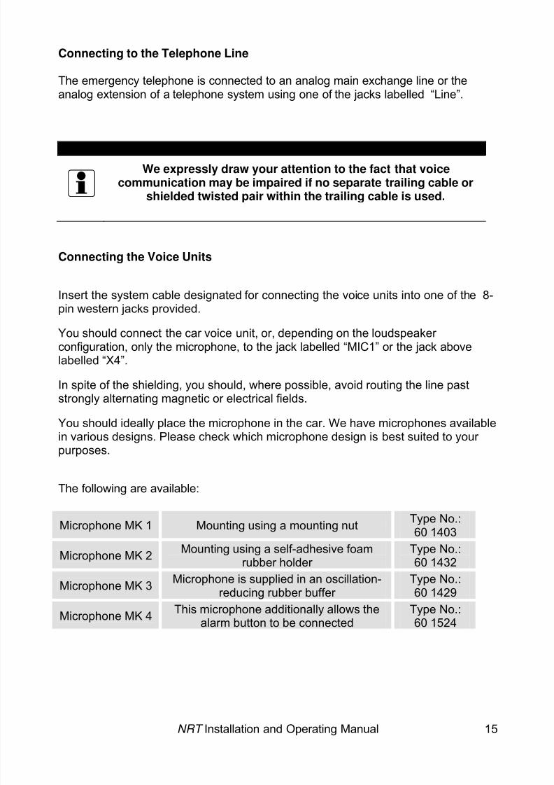
Connecting to the Telephone Line ...................................................................... 15 Connecting the Voice Units.................................................................................15 Mounting Variants ............................................................................................... 16 Connecting and Configuring the Alarm Buttons .................................................. 17 Connecting Misuse Detection..............................................................................17 Connecting the Panel Displays ........................................................................... 18 Configuring the Jumper.......................................................................................19
Parallel Switching of NRT 1 / 2 NT+..................................................................... 20
Installation........................................................................................................... 20 Important Planning Information ........................................................................... 20
8/6/2019 Bedienungsanleitung NRT en Stand 10-04-2008
http://slidepdf.com/reader/full/bedienungsanleitung-nrt-en-stand-10-04-2008 4/52
NRT Installation and Operating Manual 2
Starting Up ............................................................................................................ 22
Adjusting Loudspeaker and Microphone ............................................................. 22
Functional Description......................................................................................... 23
Alarm Release.....................................................................................................23 Alarm Filtering (Misuse Detection) ...................................................................... 24 Dialling ................................................................................................................ 24 Calming Text Played into the Car........................................................................24 Data Protocol ...................................................................................................... 24 Voice Connection ................................................................................................ 24 Ending the Voice Connection..............................................................................24 Alarm End ........................................................................................................... 25 Calling ................................................................................................................. 25 Timer Function .................................................................................................... 25
Tone Signals ....................................................................................................... 25 How to Program Using the Telephone................................................................26
Programming Access .......................................................................................... 26 Operating Modes.................................................................................................26 Overview of Telephone Commands .................................................................... 28 Description of the Individual Commands.............................................................30 Description of the Individual Commands.............................................................30 Example of How to Program Using the Telephone ............................................. 45
Battery Replacement ............................................................................................ 47
Troubleshooting ................................................................................................... 48
Legal Information..................................................................................................49
8/6/2019 Bedienungsanleitung NRT en Stand 10-04-2008
http://slidepdf.com/reader/full/bedienungsanleitung-nrt-en-stand-10-04-2008 5/52
General
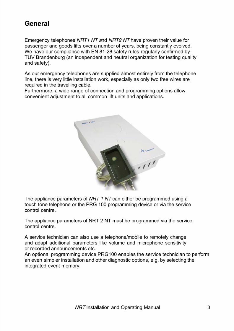
Emergency telephones NRT1 NT a nd NRT2 NT have proven their value for passenger and goods lifts over a number of years, being constantly evolved.We have our compliance with EN 81-28 safety rules regularly confirmed by
TÜV Brandenburg (an independent and neutral organization for testing qualityand safety).
As our emergency telephones are supplied almost entirely from the telephoneline, there is very little installation work, especially as only two free wires arerequired in the travelling cable.Furthermore, a wide range of connection and programming options allowconvenient adjustment to all common lift units and applications.
The appliance parameters of NRT 1 NT can either be programmed using atouch tone telephone or the PRG 100 programming device or via the servicecontrol centre.
The appliance parameters of NRT 2 NT must be programmed via the servicecontrol centre.
A service technician can also use a telephone/mobile to remotely changeand adapt additional parameters like volume and microphone sensitivityor recorded announcements etc.An optional programming device PRG100 enables the service technician to performan even simpler installation and other diagnostic options, e.g. by selecting theintegrated event memory.
NRT Installation and Operating Manual 3
8/6/2019 Bedienungsanleitung NRT en Stand 10-04-2008
http://slidepdf.com/reader/full/bedienungsanleitung-nrt-en-stand-10-04-2008 6/52
NRT Installation and Operating Manual 4
• • • • • • • • •
• • • • • • •
•
•
• •
General Performance Features of the Emergency Calling System
Connection to analog a/b telephone connection, main line or extensionExchange-supplied, i.e. no additional external electricity supply requiredDial pulse (DP) or touch tone dial (DTMF) modes available
A timer number with up to 25 digits for cyclical self-testRoutine call can be connected to a Telegärtner control centreConvenient two-way speech communication (hands-free)Acoustic and/or optical signalling of an alarmAlarm button configurable as NC or NOMicrophone and loudspeaker level can be fine-tuned via touch tonetelephone
Programmable talk-time limitOptionally activatable incoming call/eavesdropping protectionBattery-buffered real-time clock for timer calls (routine calls)Dial parameters programmable by control centreSwitching outputs to control panel displaysVoltage input for alarm filtering ( misuse detection)Event memory (with time/date details)
Automatic line adjustment for best possible voice communication
Additional Features of NRT 1 NT Automatic exchange detection and code for outside line for operation onprivate branch exchangesVoice recording for announcementsUp to 4 emergency numbers with a maximum of 25 digits
• Free assignment of alarm/timer destinations:To telephones with recorded announcements, e.g. to caretaker or
janitor To Telegärtner control centres with data protocol
Additional Features of NRT 1 NT iS• Automatic exchange detection and code for outside line for operation on
private branch exchanges
•
Free assignment of alarm/timer destinations:• To telephones with recorded announcements, e.g. to caretaker or janitor To Telegärtner control centres with data protocol
8/6/2019 Bedienungsanleitung NRT en Stand 10-04-2008
http://slidepdf.com/reader/full/bedienungsanleitung-nrt-en-stand-10-04-2008 7/52
NRT Installation and Operating Manual 5
• • •
• • •
Up to 4 emergency numbers with a maximum of 25 digitsVoice recording for announcementsInternal loudspeaker can be used as central loudspeaker, i.e. no longer necessary to mount a loudspeaker module in the car
Additional Features of NRT 2 NTTwo emergency numbers for connection to control centre
Built-in internal voice module, as well as a lift car voice module available
Internal loudspeaker can be used as central loudspeaker, i.e. no longer necessary to mount a loudspeaker module in the car
Technical Data
Telecommunications Data:Line Voltage 24 – 64 V DCLine Current 20 – 50 mA (current limit)Ring Voltage 32 – 75 V, 23 – 28 Hz
42 – 75 V, 50 HzDial Modes IWV und MFVPulse Dial Ratio 40/60ms
Alarm Voice Units:
Type of Voice Unit Telegärtner SM1or DLS1 voice moduleVolume Adjustable in 31 levels in 1.5 dB steps
(-14.5 to 32 dB)Speaker Output 200 mW peak at 50 OhmMicrophone Sensitivity Adjustable in 4 levels
(19, 25, 31 or 37 dB)
Special Functions:
Alarm Filtering Input for voltage ranging between 9 and
36 V AC/DCDisplay Control Switch Two floating outputs,
max. 30 V, 1 A DCmax. 125 V, 0.5 A AC
Timer Calls Daily, every 3 days, weekly, monthly, interval
General Data:Operating Temperature 0 – 40 °C
Dimensions (155 x 217 x 61) mm
8/6/2019 Bedienungsanleitung NRT en Stand 10-04-2008
http://slidepdf.com/reader/full/bedienungsanleitung-nrt-en-stand-10-04-2008 8/52
NRT Installation and Operating Manual 6
Additional Features in NRT 1 NT and NRT 1 NT iS
Voice Announcements
Memory In battery-supported memory
Recorded Text Up to20 secondsCalming Text Up to 5 secondsEnd Text Up to 5 seconds
Call Numbers
Alarm Number Up to 4 numbers, with up to 25 digits eachService Number 1 number with up to 25 digitsNumber of Dialling Attempts Up to 12
Voice Units
No of Voice Units Up to 3Type of voice unit Telegärtner SM1 or DLS1 voice module
Additional in NRT 2 NT
Call NumbersAlarm number Up to 2 numbers, with up to 25 digits eachService Number 1 number with up to 25 digitsDialling Attempts Up to 12
Voice Units
Voice Units One internal and one externalType of ext. voice unit Telegärtner SM1or DLS1 voice module

8/6/2019 Bedienungsanleitung NRT en Stand 10-04-2008
http://slidepdf.com/reader/full/bedienungsanleitung-nrt-en-stand-10-04-2008 9/52
Mounting Location and Installation
NRT has been designed to be mounted on the lift cage. The car voice unit can beconnected directly to NRT using the system cable.
The wire-saving two-wire technology means that only the exchange line needs to be
routed via the trailing cable and connected to NRT .
TAE-telephonesocket type “F”
Cable box
car
NRT
car well
Engine room
NRT, with internalvoice unit,strain relief
First voice unit,SM1
Travelling cable
NRT Installation and Operating Manual 7
8/6/2019 Bedienungsanleitung NRT en Stand 10-04-2008
http://slidepdf.com/reader/full/bedienungsanleitung-nrt-en-stand-10-04-2008 10/52
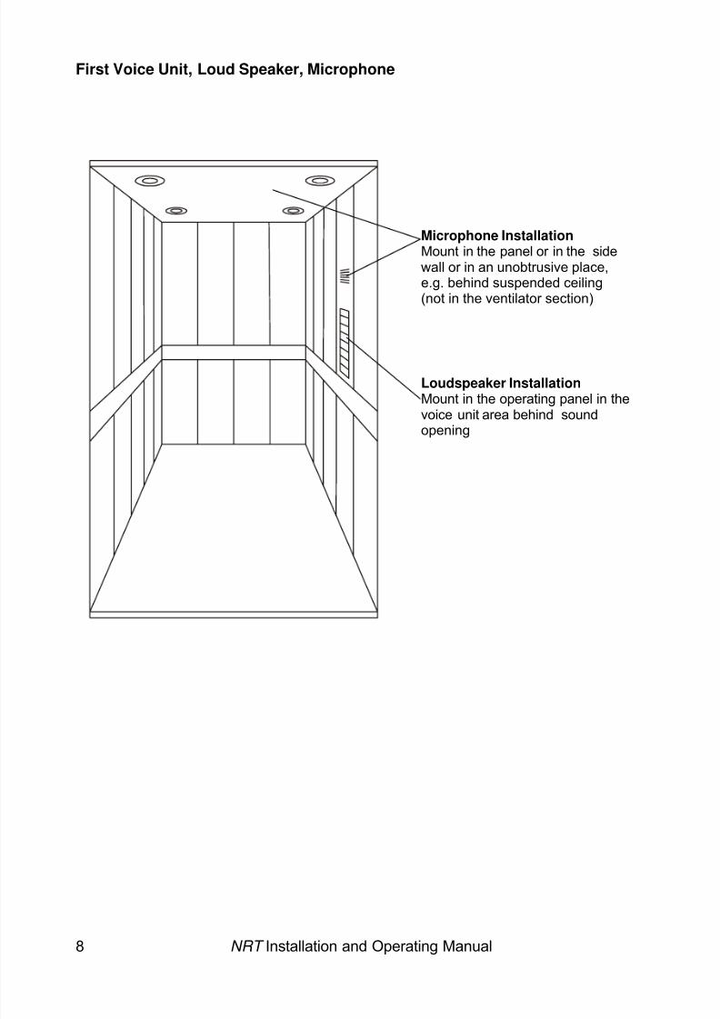
First Voice Unit, Loud Speaker, Microphone
NRT Installation and Operating Manual 8
Microphone Installation Mount in the panel or in the sidewall or in an unobtrusive place,e.g. behind suspended ceiling(not in the ventilator section)
Loudspeaker InstallationMount in the operating panel in thevoice unit area behind soundopening
8/6/2019 Bedienungsanleitung NRT en Stand 10-04-2008
http://slidepdf.com/reader/full/bedienungsanleitung-nrt-en-stand-10-04-2008 11/52
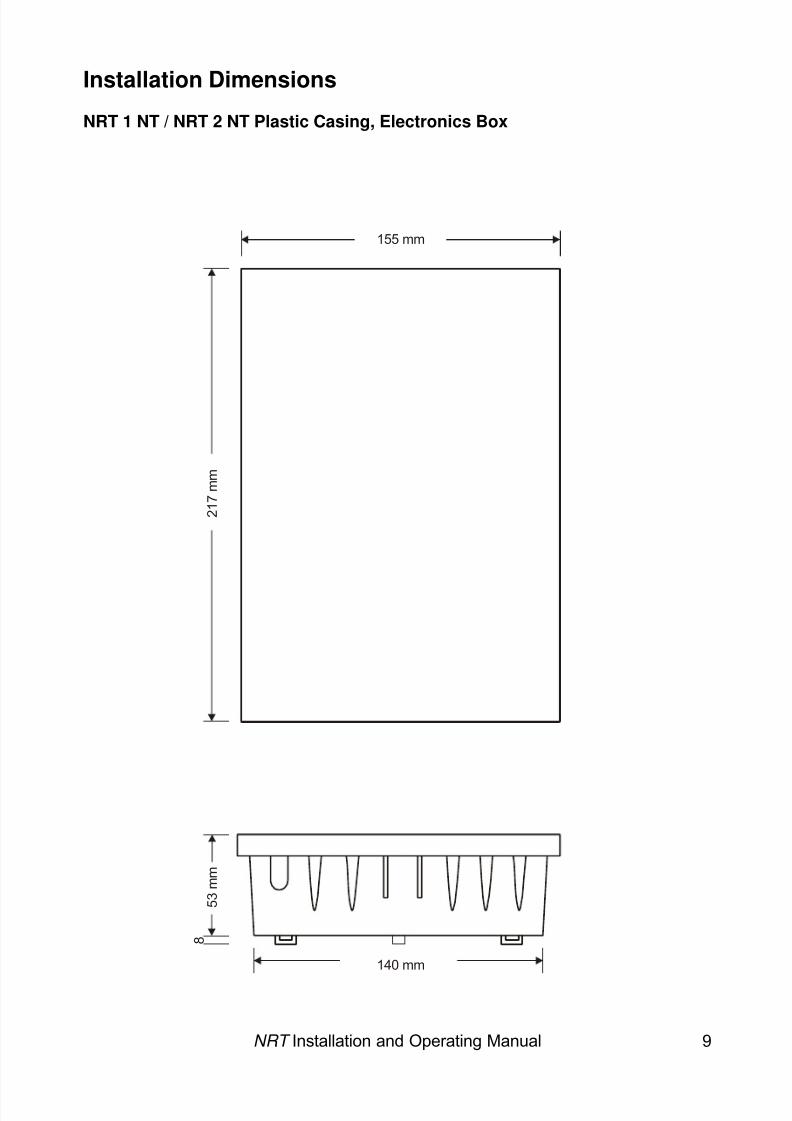
Installation Dimensions
NRT 1 NT / NRT 2 NT Plastic Casing, Electronics Box
155 mm
2 1 7 m m
5 3 m m
140 mm
8
NRT Installation and Operating Manual 9
8/6/2019 Bedienungsanleitung NRT en Stand 10-04-2008
http://slidepdf.com/reader/full/bedienungsanleitung-nrt-en-stand-10-04-2008 12/52
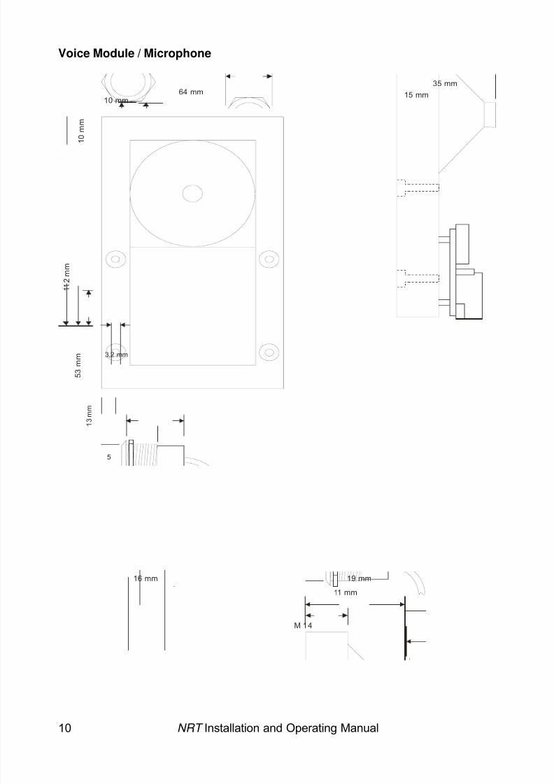
Voice Module / Microphone
19 mm
11 mm
M 14
16 mm
1 1 2 m
m
5 3 m m
1 3 m m
1 0
m m
64 mm10 mm
5
15 mm35 mm
3,2 mm
NRT Installation and Operating Manual 10
8/6/2019 Bedienungsanleitung NRT en Stand 10-04-2008
http://slidepdf.com/reader/full/bedienungsanleitung-nrt-en-stand-10-04-2008 13/52
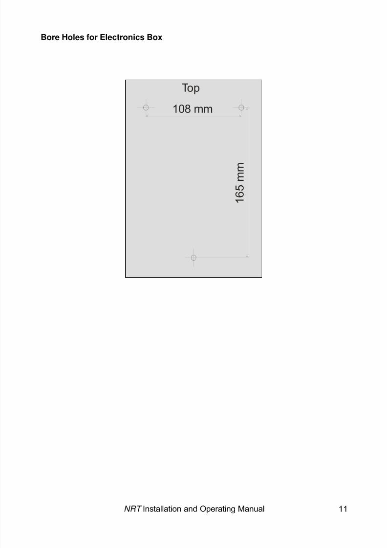
Bore Holes for Electronics Box
Top
108 mm
1 6 5 m m
NRT Installation and Operating Manual 11
8/6/2019 Bedienungsanleitung NRT en Stand 10-04-2008
http://slidepdf.com/reader/full/bedienungsanleitung-nrt-en-stand-10-04-2008 14/52
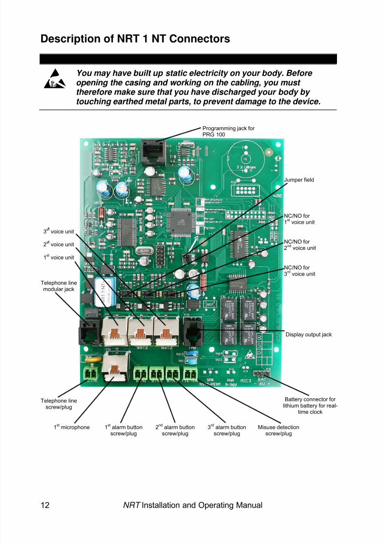
Description of NRT 1 NT Connectors
ESD WARNING
You may have built up static electricity on your body. Before opening the casing and working on the cabling, you must
therefore make sure that you have discharged your body by touching earthed metal parts, to prevent damage to the device.
NRT Installation and Operating Manual 12
Jumper field
1st microphone
1st voice unit
Telephone linemodular jack
Telephone linescrew/plug
Battery connector for lithium battery for real-
time clock
Display output jack
1st alarm buttonscrew/plug
2nd alarm buttonscrew/plug
Misuse detectionscrew/plug
2s voice unit
3rd alarm buttonscrew/plug
3s voice unit
NC/NO for 1st voice unit
NC/NO for 2nd voice unit
NC/NO for 3rd voice unit
Programming jack for PRG 100
8/6/2019 Bedienungsanleitung NRT en Stand 10-04-2008
http://slidepdf.com/reader/full/bedienungsanleitung-nrt-en-stand-10-04-2008 15/52
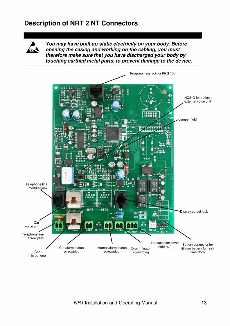
Description of NRT 2 NT Connectors
ESD WARNING
You may have built up static electricity on your body. Before opening the casing and working on the cabling, you must
therefore make sure that you have discharged your body by touching earthed metal parts, to prevent damage to the device.
NRT Installation and Operating Manual 13
Programming jack for PRG 100
NC/NO for optionalexternal voice unit
Jumper field
Telephone linemodular jack
Display output jack
Car voice unit
Telephone linescrew/plug
Loudspeaker cover
Car microphone
Car alarm buttonscrew/plug
Discriminator screw/plug
Internal alarm buttonscrew/plug
(internal) Battery connector for lithium battery for real-
time clock
8/6/2019 Bedienungsanleitung NRT en Stand 10-04-2008
http://slidepdf.com/reader/full/bedienungsanleitung-nrt-en-stand-10-04-2008 16/52
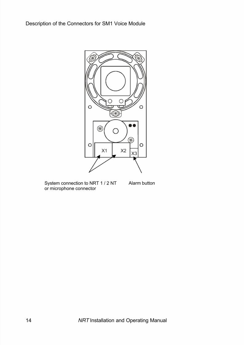
Description of the Connectors for SM1 Voice Module
X1 X2 X3
NRT Installation and Operating Manual 14
System connection to NRT 1 / 2 NTor microphone connector
Alarm button
8/6/2019 Bedienungsanleitung NRT en Stand 10-04-2008
http://slidepdf.com/reader/full/bedienungsanleitung-nrt-en-stand-10-04-2008 17/52
8/6/2019 Bedienungsanleitung NRT en Stand 10-04-2008
http://slidepdf.com/reader/full/bedienungsanleitung-nrt-en-stand-10-04-2008 18/52
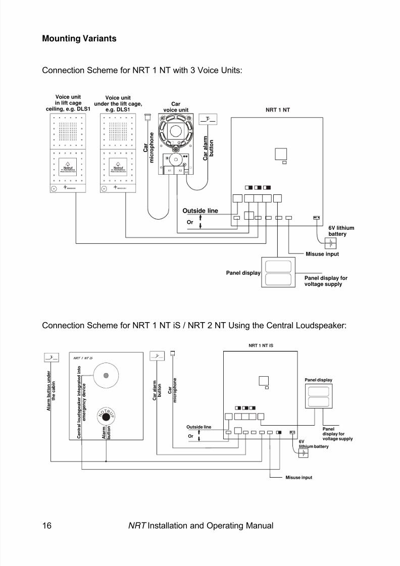
Mounting Variants
Connection Scheme for NRT 1 NT with 3 Voice Units:
Connection Scheme for NRT 1 NT iS / NRT 2 NT Using the Central Loudspeaker:
NotrufIm Alarmfallmind.
3Sekunden drückenX1 X2
X3
NotrufIm Alarmfall mind.
3Sekunden drücken
Voice unitin lift cageceiling, e.g. DLS1
Voice unitunder the lift cage,e.g. DLS1
C a r
m i c r o p
h o n e
Carvoice unit
C a r a
l a r m
b u
t t o n
NRT Installation and Operating Manual 16
C a r
m i c r o p
h o n e
C a r a l a r m
b
u t t o n
Panel display
6Vlithium battery
Misuse input
NRT 1 NT iS
Outside line
Or
N O TR U
F
NRT 1 NT iS
A l a r m b u
t t o n u n
d e r
t h e c a b
i n
C e n
t r a l l o u
d s p e a
k e r
i n t e g r a
t e d i n t o
e m e r g e n c y d
e v
i c e
A l a r m
b u
t t o n Panel
display forvoltage supply
Panel display
6V lithiumbattery
Misuse input
NRT 1 NT
Outside line
Or
Panel display forvoltage supply
8/6/2019 Bedienungsanleitung NRT en Stand 10-04-2008
http://slidepdf.com/reader/full/bedienungsanleitung-nrt-en-stand-10-04-2008 19/52
Connecting and Configuring the Alarm Buttons
Please be sure to note the following points when connecting the alarm buttons:
1. The alarm button must always be completely floating and unearthed, i.e. noexternal voltage (e.g. well buzzer) or condensers against protective earth!
2. Keep the supply line to the alarm button as short as possible ( ≤ 5 metres).Do not route the alarm button via the travelling cable, as proper functioning of NRT 1/ 2 NT will otherwise no longer be guaranteed. Should a longer supplyline be required, replace the alarm button contact on NRT 1 / 2 NT with a relaycontact or our alarm raiser NRG 1 . You will then be able to use a longer line toactivate the relay / NRG 1 .
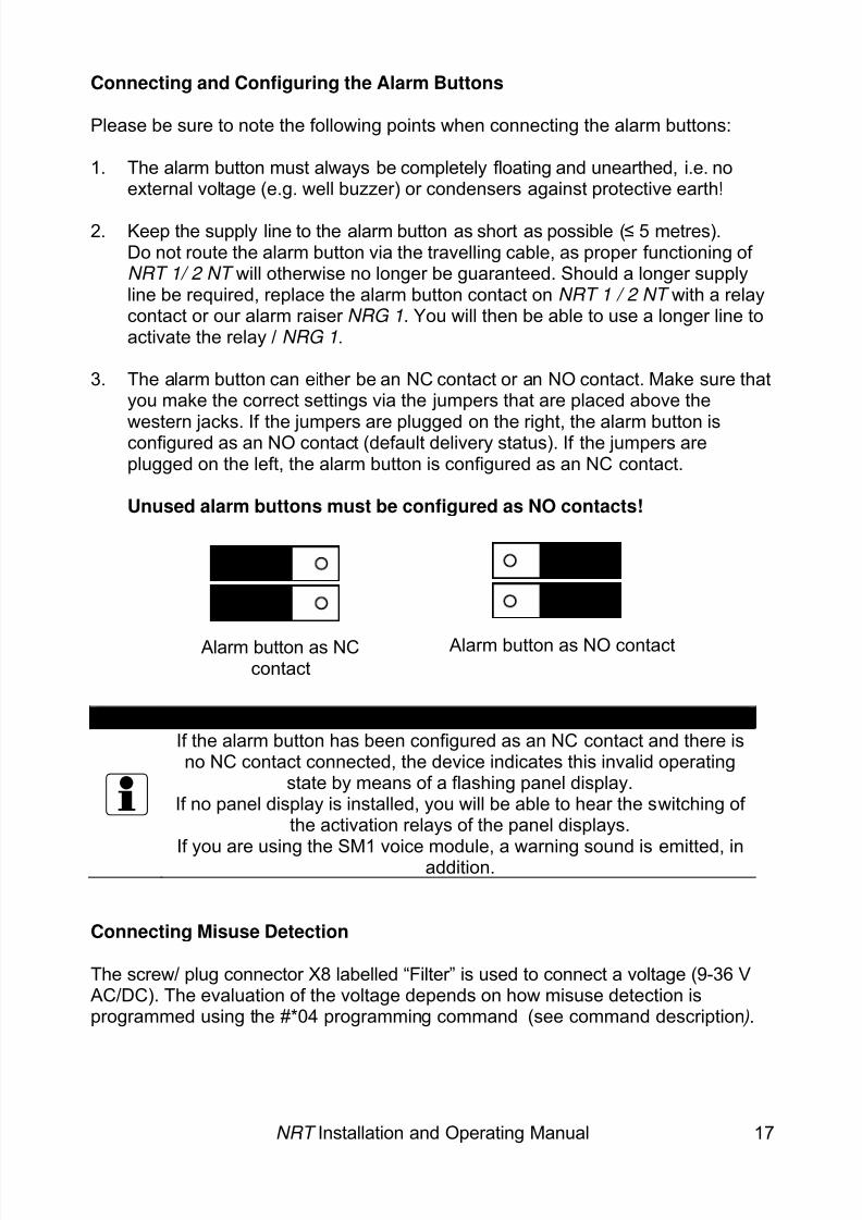
3. The alarm button can either be an NC contact or an NO contact. Make sure thatyou make the correct settings via the jumpers that are placed above the
western jacks. If the jumpers are plugged on the right, the alarm button isconfigured as an NO contact (default delivery status). If the jumpers areplugged on the left, the alarm button is configured as an NC contact.
Unused alarm buttons must be configured as NO contacts!
NRT Installation and Operating Manual 17
Note:
If the alarm button has been configured as an NC contact and there isno NC contact connected, the device indicates this invalid operating
state by means of a flashing panel display.If no panel display is installed, you will be able to hear the switching of
the activation relays of the panel displays.
If you are using the SM1 voice module, a warning sound is emitted, inaddition.
Connecting Misuse Detection
The screw/ plug connector X8 labelled “Filter” is used to connect a voltage (9-36 VAC/DC). The evaluation of the voltage depends on how misuse detection isprogrammed using the #*04 programming command (see command description ).
Alarm button as NCcontact
Alarm button as NO contact
8/6/2019 Bedienungsanleitung NRT en Stand 10-04-2008
http://slidepdf.com/reader/full/bedienungsanleitung-nrt-en-stand-10-04-2008 20/52
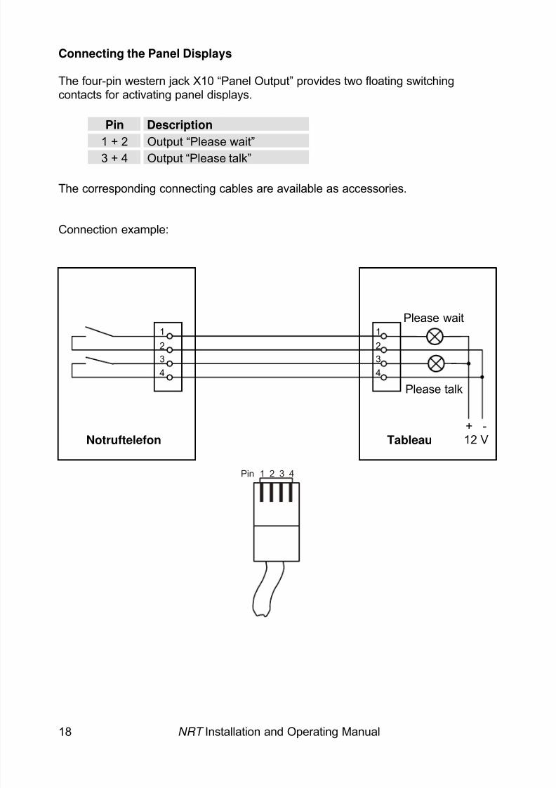
Connecting the Panel Displays
The four-pin western jack X10 “Panel Output” provides two floating switchingcontacts for activating panel displays.
NRT Installation and Operating Manual 18
Pin Description
1 + 2 Output “Please wait”3 + 4 Output “Please talk”
The corresponding connecting cables are available as accessories.
Connection example:
+ -12 VNotruftelefon Tableau
Please wait
Please tal
1234
1234
k
1 2 3 4Pin
8/6/2019 Bedienungsanleitung NRT en Stand 10-04-2008
http://slidepdf.com/reader/full/bedienungsanleitung-nrt-en-stand-10-04-2008 21/52
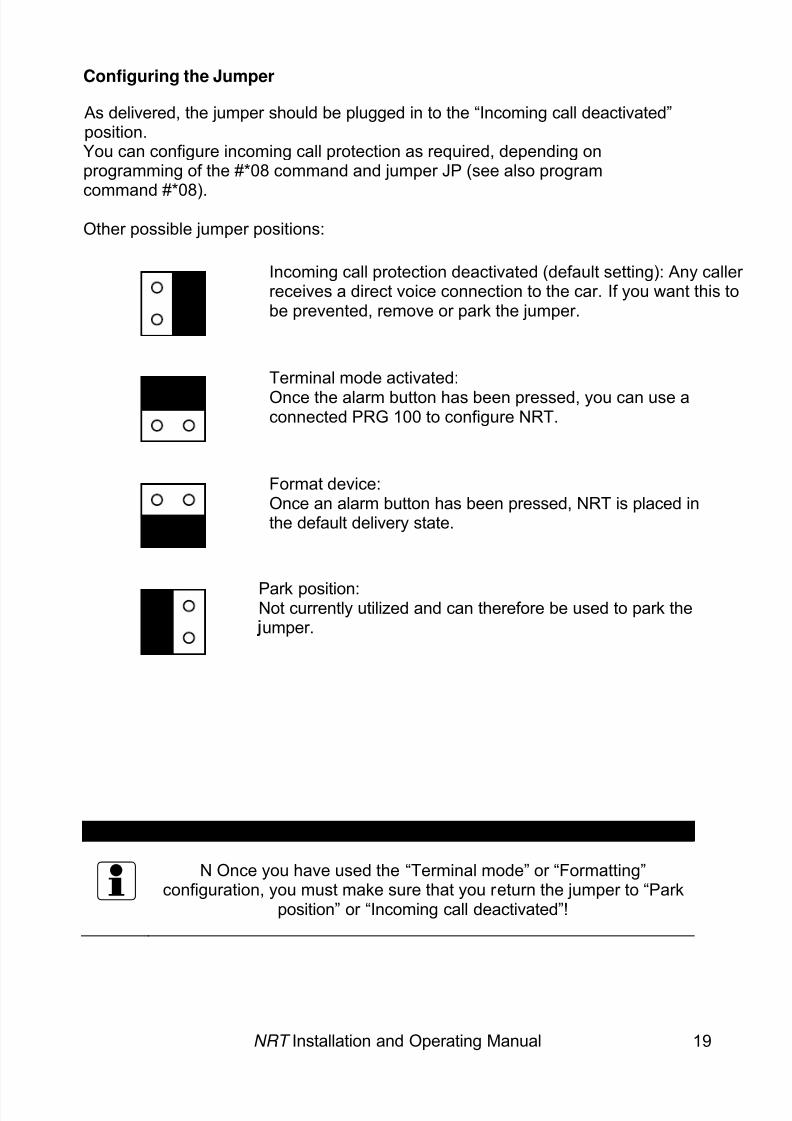
Configuring the Jumper
As delivered, the jumper should be plugged in to the “Incoming call deactivated”position.You can configure incoming call protection as required, depending onprogramming of the #*08 command and jumper JP (see also program
command #*08).Other possible jumper positions:
Incoming call protection deactivated (default setting): Any caller receives a direct voice connection to the car. If you want this tobe prevented, remove or park the jumper.
NRT Installation and Operating Manual 19
Terminal mode activated:
VERY IMPORTANT:
N Once you have used the “Terminal mode” or “Formatting”configuration, you must make sure that you return the jumper to “Park
position” or “Incoming call deactivated”!
Once the alarm button has been pressed, you can use aconnected PRG 100 to configure NRT.
Format device:Once an alarm button has been pressed, NRT is placed inthe default delivery state.
Park position:Not currently utilized and can therefore be used to park theumper.
8/6/2019 Bedienungsanleitung NRT en Stand 10-04-2008
http://slidepdf.com/reader/full/bedienungsanleitung-nrt-en-stand-10-04-2008 22/52
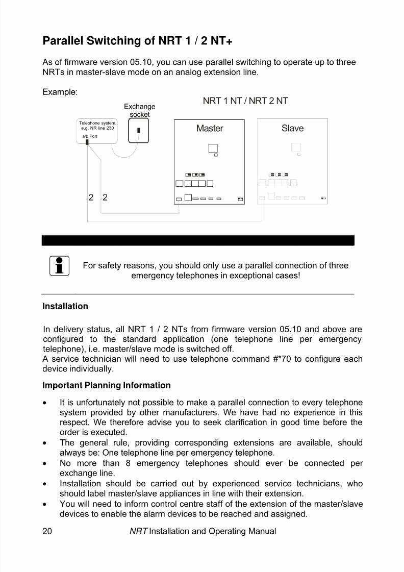
Parallel Switching of NRT 1 / 2 NT+
As of firmware version 05.10, you can use parallel switching to operate up to threeNRTs in master-slave mode on an analog extension line.
Example:NRT 1 NT / NRT 2 NT
Master SlaveTelephone system,
e.g. NR line 230
22
Exchangesocket
a/b Port
Note:
For safety reasons, you should only use a parallel connection of threeemergency telephones in exceptional cases!
Installation
In delivery status, all NRT 1 / 2 NTs from firmware version 05.10 and above areconfigured to the standard application (one telephone line per emergencytelephone), i.e. master/slave mode is switched off.A service technician will need to use telephone command #*70 to configure eachdevice individually.
Important Planning Information
• It is unfortunately not possible to make a parallel connection to every telephonesystem provided by other manufacturers. We have had no experience in thisrespect. We therefore advise you to seek clarification in good time before theorder is executed.
• The general rule, providing corresponding extensions are available, shouldalways be: One telephone line per emergency telephone.
• No more than 8 emergency telephones should ever be connected per exchange line.
• Installation should be carried out by experienced service technicians, whoshould label master/slave appliances in line with their extension.
• You will need to inform control centre staff of the extension of the master/slavedevices to enable the alarm devices to be reached and assigned.
NRT Installation and Operating Manual 20
8/6/2019 Bedienungsanleitung NRT en Stand 10-04-2008
http://slidepdf.com/reader/full/bedienungsanleitung-nrt-en-stand-10-04-2008 23/52
NRT Installation and Operating Manual 21
Note:
You cannot make a direct parallel connection to main exchange lines(e.g. Deutsche Telekom AG), as conformity is no longer guaranteed. A
telephone system always needs to be interposed.
Tested TC Systems:
Telegärtner NR-Line 230, NR-Line 024, NR-Line iSDN, Compakt 600Compakt 600a, Compakt 400, Compakt 400 (SF)
Auerswald Commander Basic(Only two emergency telephones per a/b port allowed)
8/6/2019 Bedienungsanleitung NRT en Stand 10-04-2008
http://slidepdf.com/reader/full/bedienungsanleitung-nrt-en-stand-10-04-2008 24/52
NRT Installation and Operating Manual 22
⇒ ⇒ ⇒
Starting Up
Once the emergency telephone NRT 1 / 2 NT has been installed as intended, youneed to program the desired parameters like call number, dial mode, etc. Inaddition, you can adjust loudspeaker and microphone to the ambient conditions.
If the lift phone connects to a service control centre:
1. Ask the control centre to program the device2. Record any announcements
(see telephone programming)3. Configure sound level, microphone (see page 23)4. Perform alarm test
If the lift phone connects to a caretaker / janitor (Attention: applies only to NRT 1 NT (iS)):
1. Use telephone programming to enter dialling parameters(see example programming)
2. Record any announcements(see telephone programming)
3. Configure sound level, microphone (see page 23)4. Perform alarm test
For mixed connection to control centre and caretaker / janitor (Attention: applies only to NRT 1 NT (iS)):
1. Ask the control centre to program the device2. Use telephone programming to enter operation mode and destination ID
(see example programming)3. Record any announcements (see telephone programming)4. Configure sound level, microphone (see page 23)5. Perform alarm test
Adjusting Loudspeaker and Microphone
1. Call NRT 1 2 NT from a telephone, and enter the security code (default setting0000) within 2 seconds of hearing the first beep, in order to accessprogramming mode.
NRT 1 / 2 NT emits 1 beep if you enter the correct security codeif you enter an incorrect security code, the device hangs upyou are now in programming mode (cf. programming start).
8/6/2019 Bedienungsanleitung NRT en Stand 10-04-2008
http://slidepdf.com/reader/full/bedienungsanleitung-nrt-en-stand-10-04-2008 25/52
NRT Installation and Operating Manual 23
⇒
Adjusting Loudspeaker and Microphone
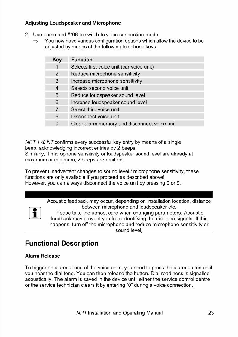
2. Use command #*06 to switch to voice connection modeYou now have various configuration options which allow the device to beadjusted by means of the following telephone keys:
Key Function1 Selects first voice unit (car voice unit)2 Reduce microphone sensitivity3 Increase microphone sensitivity4 Selects second voice unit5 Reduce loudspeaker sound level6 Increase loudspeaker sound level7 Select third voice unit
9 Disconnect voice unit0 Clear alarm memory and disconnect voice unit
NRT 1 /2 NT confirms every successful key entry by means of a singlebeep, acknowledging incorrect entries by 2 beeps.Similarly, if microphone sensitivity or loudspeaker sound level are already atmaximum or minimum, 2 beeps are emitted.
To prevent inadvertent changes to sound level / microphone sensitivity, thesefunctions are only available if you proceed as described above!However, you can always disconnect the voice unit by pressing 0 or 9.
Note:
Acoustic feedback may occur, depending on installation location, distance
between microphone and loudspeaker etc.Please take the utmost care when changing parameters. Acoustic
feedback may prevent you from identifying the dial tone signals. If thishappens, turn off the microphone and reduce microphone sensitivity or
sound level!
Functional Description
Alarm Release
To trigger an alarm at one of the voice units, you need to press the alarm button untilyou hear the dial tone. You can then release the button. Dial readiness is signalledacoustically. The alarm is saved in the device until either the service control centreor the service technician clears it by entering “0” during a voice connection.
8/6/2019 Bedienungsanleitung NRT en Stand 10-04-2008
http://slidepdf.com/reader/full/bedienungsanleitung-nrt-en-stand-10-04-2008 26/52
NRT Installation and Operating Manual 24
Alarm Filtering (Misuse Detection)Alarm filtering is used to filter out false alarms or to delay the alarm. If the functionhas been programmed accordingly and the conditions are met, the alarm issuppressed and the device hangs up. Alarm filtering is deactivated for a previouslysaved alarm, i.e. until a voice connection is acknowledged through “0”.
DiallingIf the alarm has been accepted as a genuine alarm, the panel output “Pleasewait” is activated and the device dials the first programmed emergencynumber. You will be able to hear the dial tones and the call progress tones fromthe loudspeaker.If the alarm destination does not answer immediately (engaged, wrong number), thedevice hangs up and re-dials after 10 seconds, with the number of redials beinglimited to a maximum of 12. If the service control unit answers, the loudspeaker isswitched off for the duration of the data protocol.
Calming Text Played into the Car(Attention: only for NRT 1 NT) To calm the trapped person, it is possible to pipe a self-recorded announcement intothe car. This announcement is generally repeated once per dialling attempt. You canonly record, monitor and activate announcements via telephone programming.
Data ProtocolIf it was possible to reach the alarm centre, a data protocol transfer is made toenable the emergency device to be identified and assigned. Should the dataprotocol have an error, the dial attempts are continued. If the protocol was
successful, the control centre pipes an announcement into the car until the operator accepts the alarm.
Voice ConnectionIf the alarm was executed successfully, voice connection is activated. The voiceunit that has triggered the last alarm is always automatically activated!To signal its readiness to receive voice input, the panel display shows “Pleasespeak”, and a 4-tone sound is emitted in the lift car.
Ending the Voice ConnectionNRT 1 / 2 NT automatically identifies by means of an engaged tone when the voiceconnection has been discontinued and then also hangs up. Otherwise, the voiceconnection is automatically discontinued once the programmed communication timehas elapsed. The operator may also use key command “9” to hang up directly.
8/6/2019 Bedienungsanleitung NRT en Stand 10-04-2008
http://slidepdf.com/reader/full/bedienungsanleitung-nrt-en-stand-10-04-2008 27/52
NRT Installation and Operating Manual 25
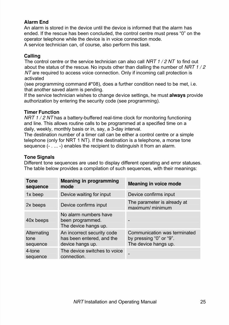
Alarm EndAn alarm is stored in the device until the device is informed that the alarm hasended. If the rescue has been concluded, the control centre must press “0” on theoperator telephone while the device is in voice connection mode.A service technician can, of course, also perform this task.
CallingThe control centre or the service technician can also call NRT 1 / 2 NT to find outabout the status of the rescue. No inputs other than dialling the number of NRT 1 / 2 NT are required to access voice connection. Only if incoming call protection isactivated(see programming command #*08), does a further condition need to be met, i.e.that another saved alarm is pending.If the service technician wishes to change device settings, he must always provideauthorization by entering the security code (see programming).
Timer FunctionNRT 1 / 2 NT has a battery-buffered real-time clock for monitoring functioningand line. This allows routine calls to be programmed at a specified time on adaily, weekly, monthly basis or in, say, a 3-day interval.The destination number of a timer call can be either a control centre or a simpletelephone (only for NRT 1 NT). If the destination is a telephone, a morse tonesequence (- . ... -) enables the recipient to distinguish it from an alarm.
Tone SignalsDifferent tone sequences are used to display different operating and error statuses.
The table below provides a compilation of such sequences, with their meanings:Tonesequence
Meaning in programmingmode Meaning in voice mode
1x beep Device waiting for input Device confirms input
2x beeps Device confirms input The parameter is already atmaximum/ minimum
40x beepsNo alarm numbers havebeen programmed.
The device hangs up.
-
Alternatingtonesequence
An incorrect security codehas been entered, and thedevice hangs up.
Communication was terminatedby pressing “0” or “9”.The device hangs up.
4-tonesequence
The device switches to voiceconnection. -
8/6/2019 Bedienungsanleitung NRT en Stand 10-04-2008
http://slidepdf.com/reader/full/bedienungsanleitung-nrt-en-stand-10-04-2008 28/52
NRT Installation and Operating Manual 26
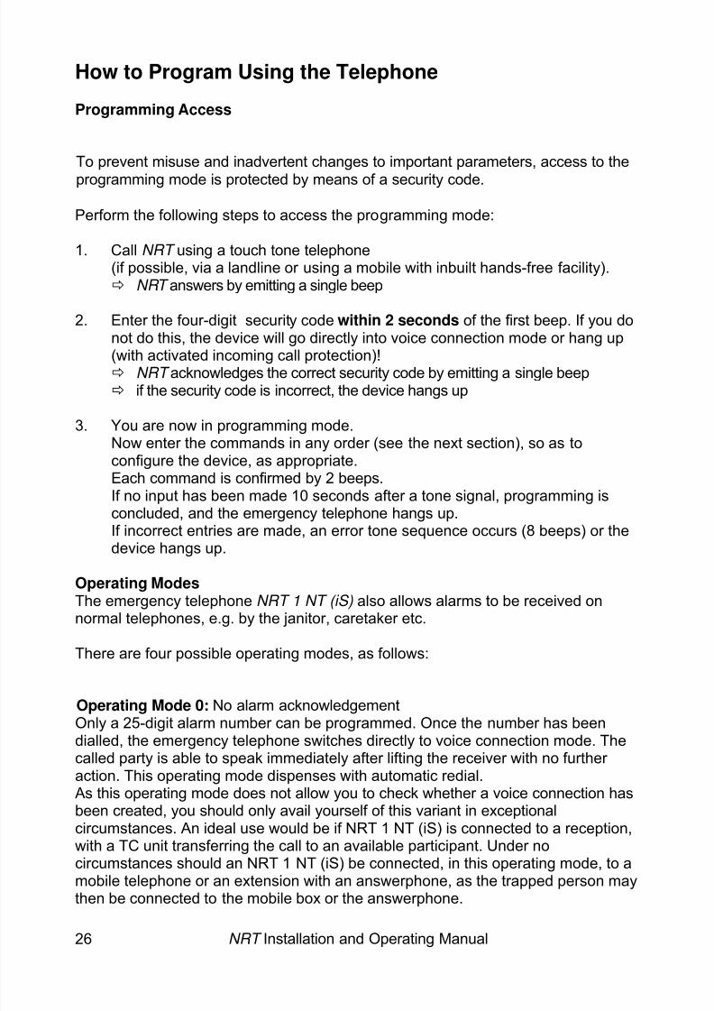
How to Program Using the Telephone
Programming Access
To prevent misuse and inadvertent changes to important parameters, access to theprogramming mode is protected by means of a security code.
Perform the following steps to access the programming mode:
1. Call NRT using a touch tone telephone(if possible, via a landline or using a mobile with inbuilt hands-free facility).
NRT answers by emitting a single beep
2. Enter the four-digit security code within 2 seconds of the first beep. If you donot do this, the device will go directly into voice connection mode or hang up(with activated incoming call protection)!
NRT acknowledges the correct security code by emitting a single beepif the security code is incorrect, the device hangs up
3. You are now in programming mode.Now enter the commands in any order (see the next section), so as toconfigure the device, as appropriate.Each command is confirmed by 2 beeps.If no input has been made 10 seconds after a tone signal, programming isconcluded, and the emergency telephone hangs up.If incorrect entries are made, an error tone sequence occurs (8 beeps) or thedevice hangs up.
Operating ModesThe emergency telephone NRT 1 NT (iS) also allows alarms to be received onnormal telephones, e.g. by the janitor, caretaker etc.
There are four possible operating modes, as follows:
Operating Mode 0: No alarm acknowledgementOnly a 25-digit alarm number can be programmed. Once the number has beendialled, the emergency telephone switches directly to voice connection mode. Thecalled party is able to speak immediately after lifting the receiver with no further action. This operating mode dispenses with automatic redial.As this operating mode does not allow you to check whether a voice connection hasbeen created, you should only avail yourself of this variant in exceptionalcircumstances. An ideal use would be if NRT 1 NT (iS) is connected to a reception,with a TC unit transferring the call to an available participant. Under nocircumstances should an NRT 1 NT (iS) be connected, in this operating mode, to a
mobile telephone or an extension with an answerphone, as the trapped person maythen be connected to the mobile box or the answerphone.
8/6/2019 Bedienungsanleitung NRT en Stand 10-04-2008
http://slidepdf.com/reader/full/bedienungsanleitung-nrt-en-stand-10-04-2008 29/52
NRT Installation and Operating Manual 27
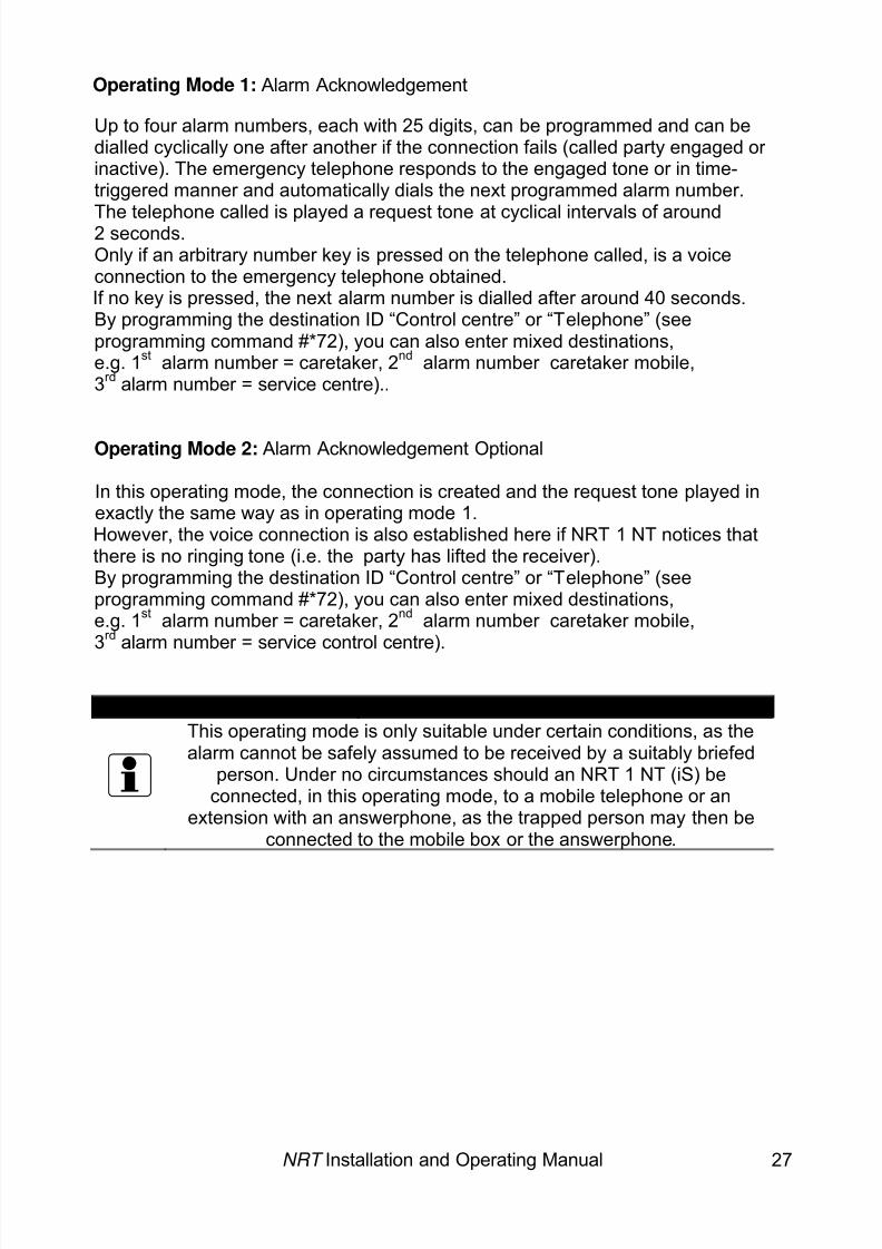
Operating Mode 1: Alarm Acknowledgement
Up to four alarm numbers, each with 25 digits, can be programmed and can bedialled cyclically one after another if the connection fails (called party engaged or inactive). The emergency telephone responds to the engaged tone or in time-triggered manner and automatically dials the next programmed alarm number.
The telephone called is played a request tone at cyclical intervals of around2 seconds.Only if an arbitrary number key is pressed on the telephone called, is a voiceconnection to the emergency telephone obtained.If no key is pressed, the next alarm number is dialled after around 40 seconds.By programming the destination ID “Control centre” or “Telephone” (seeprogramming command #*72), you can also enter mixed destinations,e.g. 1 st alarm number = caretaker, 2 nd alarm number caretaker mobile,3rd alarm number = service centre)..
Operating Mode 2: Alarm Acknowledgement Optional
In this operating mode, the connection is created and the request tone played inexactly the same way as in operating mode 1.However, the voice connection is also established here if NRT 1 NT notices thatthere is no ringing tone (i.e. the party has lifted the receiver).By programming the destination ID “Control centre” or “Telephone” (seeprogramming command #*72), you can also enter mixed destinations,e.g. 1 st alarm number = caretaker, 2 nd alarm number caretaker mobile,3rd alarm number = service control centre).
Important Information:
This operating mode is only suitable under certain conditions, as thealarm cannot be safely assumed to be received by a suitably briefed
person. Under no circumstances should an NRT 1 NT (iS) beconnected, in this operating mode, to a mobile telephone or an
extension with an answerphone, as the trapped person may then beconnected to the mobile box or the answerphone.
8/6/2019 Bedienungsanleitung NRT en Stand 10-04-2008
http://slidepdf.com/reader/full/bedienungsanleitung-nrt-en-stand-10-04-2008 30/52
NRT Installation and Operating Manual 28
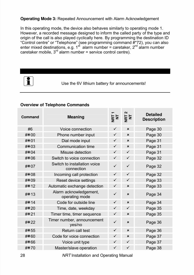
Operating Mode 3: Repeated Announcement with Alarm Acknowledgement
In this operating mode, the device also behaves similarly to operating mode 1.However, a recorded message designed to inform the called party of the type andorigin of the call is also played cyclically here. By programming the destination ID“Control centre” or “Telephone” (see programming command #*72), you can also
enter mixed destinations, e.g. 1st
alarm number = caretaker, 2nd
alarm number caretaker mobile, 3 rd alarm number = service control centre).
Note:
Use the 6V lithium battery for announcements!
Overview of Telephone Commands
Command Meaning N R T 1
N T
N R T 2
N T Detailed
Description
#6 Voice connection Page 30# 00 Phone number input Page 30# 01 Dial mode input Page 31# 03 Communication time Page 31# 04 Misuse detection Page 31# 06 Switch to voice connection Page 32
# 07 Switch to installation voiceconnection Page 32
# 08 Incoming call protection Page 32# 09 Reset device settings Page 33# 12 Automatic exchange detection Page 33
# 13 Alarm acknowledgement,operating mode Page 34
# 14 Code for outside line Page 34# 20 Time, date, weekday Page 35# 21 Timer time, timer sequence Page 35
# 22 Timer number, announcementyes/no Page 36
# 55 Return call test Page 36# 60 Code for voice connection Page 37# 66 Voice unit type Page 37# 70 Master/slave operation Page 38
8/6/2019 Bedienungsanleitung NRT en Stand 10-04-2008
http://slidepdf.com/reader/full/bedienungsanleitung-nrt-en-stand-10-04-2008 31/52
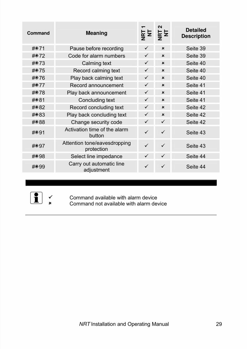
NRT Installation and Operating Manual 29
Command Meaning N R T 1
N T
N R T 2
N T Detailed
Description
# 71 Pause before recording Seite 39# 72 Code for alarm numbers Seite 39# 73 Calming text Seite 40# 75 Record calming text Seite 40# 76 Play back calming text Seite 40# 77 Record announcement Seite 41# 78 Play back announcement Seite 41# 81 Concluding text Seite 41# 82 Record concluding text Seite 42# 83 Play back concluding text Seite 42
# 88 Change security code Seite 42# 91 Activation time of the alarm
button Seite 43
# 97 Attention tone/eavesdroppingprotection Seite 43
# 98 Select line impedance Seite 44
# 99 Carry out automatic lineadjustment Seite 44
VERY IMPORTANT:
Command available with alarm deviceCommand not available with alarm device
8/6/2019 Bedienungsanleitung NRT en Stand 10-04-2008
http://slidepdf.com/reader/full/bedienungsanleitung-nrt-en-stand-10-04-2008 32/52
NRT Installation and Operating Manual 30
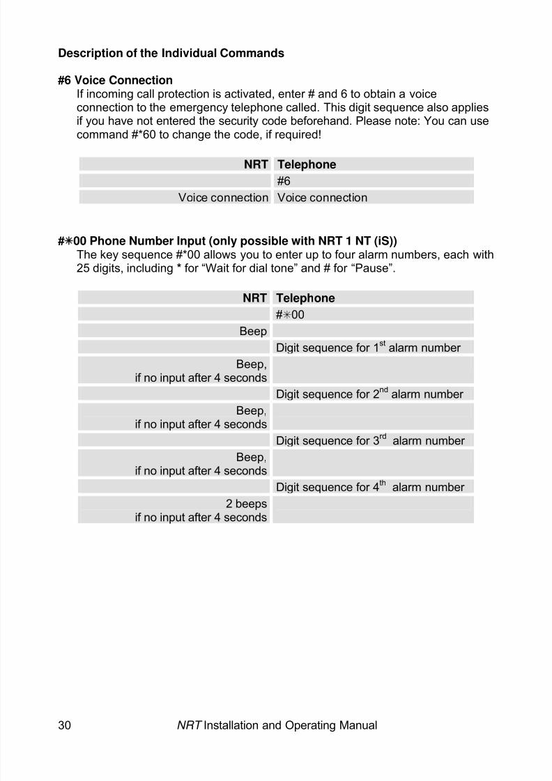
Description of the Individual Commands
#6 Voice ConnectionIf incoming call protection is activated, enter # and 6 to obtain a voiceconnection to the emergency telephone called. This digit sequence also appliesif you have not entered the security code beforehand. Please note: You can use
command #*60 to change the code, if required!
NRT Telephone#6
Voice connection Voice connection
# 00 Phone Number Input (only possible with NRT 1 NT (iS))The key sequence #*00 allows you to enter up to four alarm numbers, each with
25 digits, including * for “Wait for dial tone” and # for “Pause”.NRT Telephone
# 00Beep
Digit sequence for 1 st alarm number Beep,
if no input after 4 seconds
Digit sequence for 2 nd alarm number
Beep,if no input after 4 seconds
Digit sequence for 3 rd alarm number Beep,
if no input after 4 seconds
Digit sequence for 4 th alarm number 2 beeps
if no input after 4 seconds
8/6/2019 Bedienungsanleitung NRT en Stand 10-04-2008
http://slidepdf.com/reader/full/bedienungsanleitung-nrt-en-stand-10-04-2008 33/52
NRT Installation and Operating Manual 31
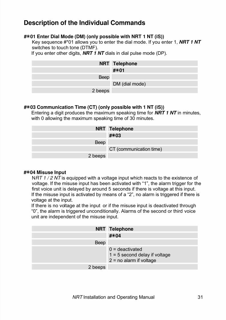
Description of the Individual Commands
# 01 Enter Dial Mode (DM) (only possible with NRT 1 NT (iS)) Key sequence #*01 allows you to enter the dial mode. If you enter 1, NRT 1 NT switches to touch tone (DTMF).If you enter other digits, NRT 1 NT dials in dial pulse mode (DP).
NRT Telephone# 01
BeepDM (dial mode)
2 beeps
# 03 Communication Time (CT) (only possible with 1 NT (iS)) Entering a digit produces the maximum speaking time for NRT 1 NT in minutes,with 0 allowing the maximum speaking time of 30 minutes.
NRT Telephone# 03
BeepCT (communication time)
2 beeps
# 04 Misuse InputNRT 1 / 2 NT is equipped with a voltage input which reacts to the existence of voltage. If the misuse input has been activated with “1”, the alarm trigger for thefirst voice unit is delayed by around 5 seconds if there is voltage at this input.If the misuse input is activated by means of a “2”, no alarm is triggered if there isvoltage at the input.If there is no voltage at the input or if the misuse input is deactivated through“0”, the alarm is triggered unconditionally. Alarms of the second or third voiceunit are independent of the misuse input.
NRT Telephone# 04
Beep0 = deactivated1 = 5 second delay if voltage2 = no alarm if voltage
2 beeps
8/6/2019 Bedienungsanleitung NRT en Stand 10-04-2008
http://slidepdf.com/reader/full/bedienungsanleitung-nrt-en-stand-10-04-2008 34/52
NRT Installation and Operating Manual 32
Description of the Individual Commands
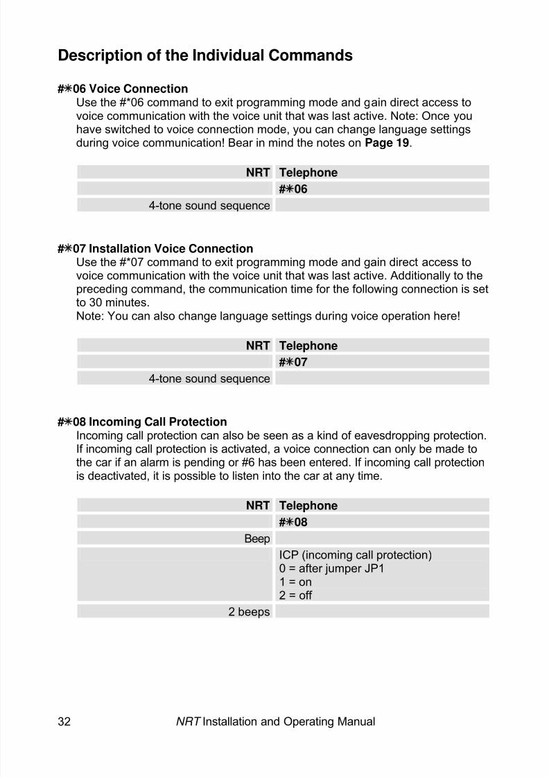
# 06 Voice ConnectionUse the #*06 command to exit programming mode and gain direct access tovoice communication with the voice unit that was last active. Note: Once youhave switched to voice connection mode, you can change language settingsduring voice communication! Bear in mind the notes on Page 19 .
NRT Telephone# 06
4-tone sound sequence
# 07 Installation Voice ConnectionUse the #*07 command to exit programming mode and gain direct access tovoice communication with the voice unit that was last active. Additionally to thepreceding command, the communication time for the following connection is setto 30 minutes.Note: You can also change language settings during voice operation here!
NRT Telephone# 07
4-tone sound sequence
# 08 Incoming Call ProtectionIncoming call protection can also be seen as a kind of eavesdropping protection.If incoming call protection is activated, a voice connection can only be made tothe car if an alarm is pending or #6 has been entered. If incoming call protectionis deactivated, it is possible to listen into the car at any time.
NRT Telephone# 08
Beep ICP (incoming call protection)0 = after jumper JP11 = on2 = off
2 beeps
8/6/2019 Bedienungsanleitung NRT en Stand 10-04-2008
http://slidepdf.com/reader/full/bedienungsanleitung-nrt-en-stand-10-04-2008 35/52
NRT Installation and Operating Manual 33
Description of the Individual Commands
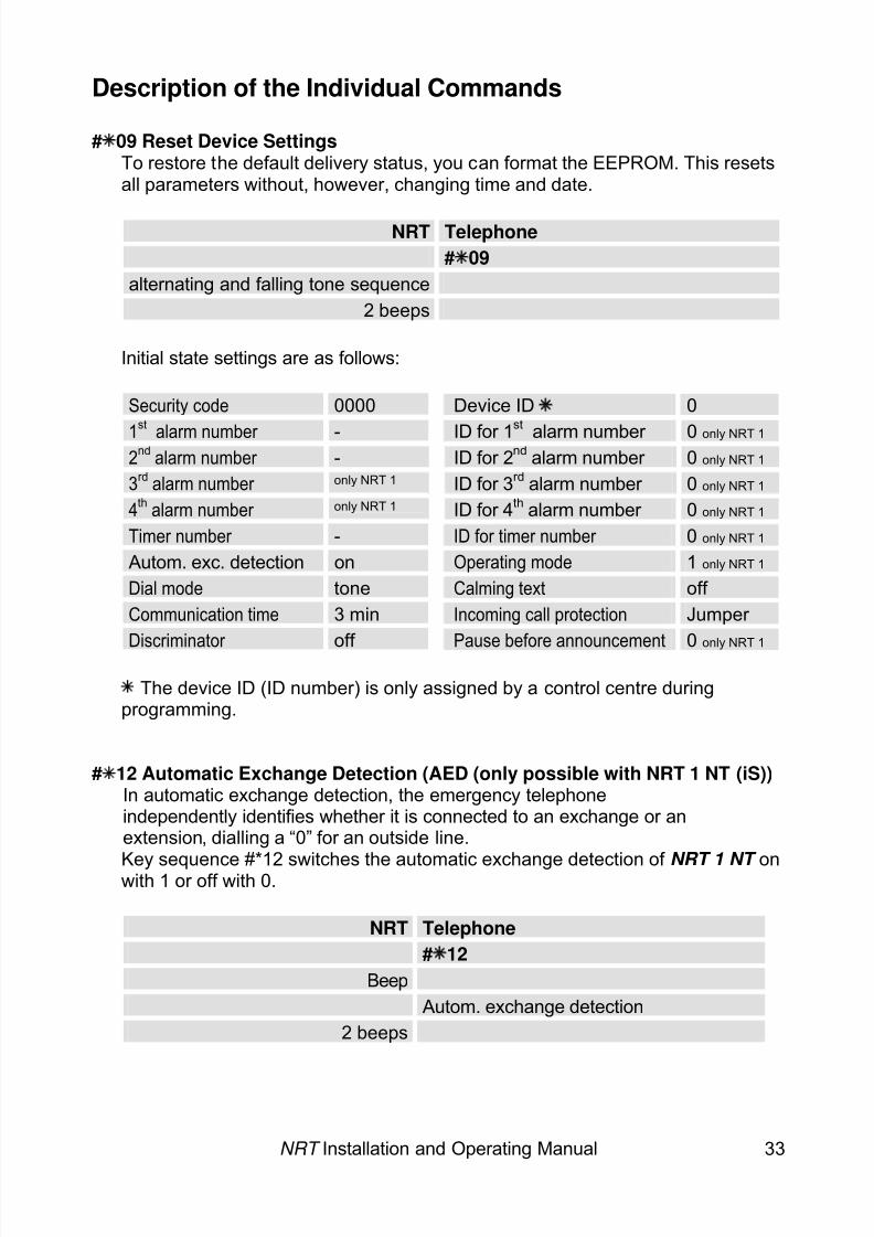
# 09 Reset Device SettingsTo restore the default delivery status, you can format the EEPROM. This resetsall parameters without, however, changing time and date.
NRT Telephone# 09
alternating and falling tone sequence2 beeps
Initial state settings are as follows:
Security code 0000 Device ID 0
1st
alarm number - ID for 1st
alarm number 0 only NRT 1 2
ndalarm number - ID for 2nd alarm number 0 only NRT 1
3rd
alarm number only NRT 1 ID for 3rd alarm number 0 only NRT 1 4
thalarm number only NRT 1 ID for 4th alarm number 0 only NRT 1
Timer number - ID for timer number 0 only NRT 1 Autom. exc. detection on Operating mode 1 only NRT 1 Dial mode tone Calming text off Communication time 3 min Incoming call protection Jumper
Discriminator off Pause before announcement 0only NRT 1
The device ID (ID number) is only assigned by a control centre during
programming.
# 12 Automatic Exchange Detection (AED (only possible with NRT 1 NT (iS))In automatic exchange detection, the emergency telephoneindependently identifies whether it is connected to an exchange or anextension, dialling a “0” for an outside line.
Key sequence #*12 switches the automatic exchange detection of NRT 1 NT on with 1 or off with 0.
NRT Telephone# 12
BeepAutom. exchange detection
2 beeps
8/6/2019 Bedienungsanleitung NRT en Stand 10-04-2008
http://slidepdf.com/reader/full/bedienungsanleitung-nrt-en-stand-10-04-2008 36/52
NRT Installation and Operating Manual 34
Description of the Individual Commands
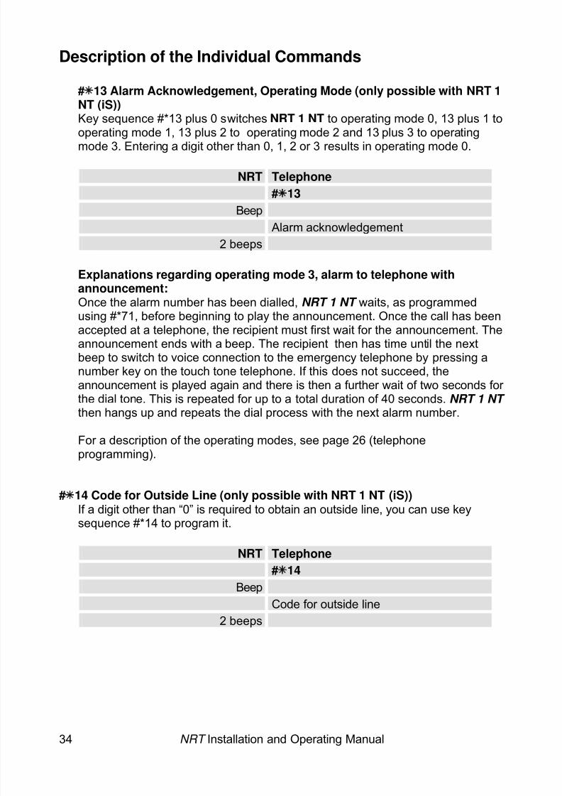
# 13 Alarm Acknowledgement, Operating Mode (only possible with NRT 1NT (iS)) Key sequence #*13 plus 0 switches NRT 1 NT to operating mode 0, 13 plus 1 tooperating mode 1, 13 plus 2 to operating mode 2 and 13 plus 3 to operatingmode 3. Entering a digit other than 0, 1, 2 or 3 results in operating mode 0.
NRT Telephone# 13
BeepAlarm acknowledgement
2 beeps
Explanations regarding operating mode 3, alarm to telephone withannouncement:Once the alarm number has been dialled, NRT 1 NT waits, as programmedusing #*71, before beginning to play the announcement. Once the call has beenaccepted at a telephone, the recipient must first wait for the announcement. Theannouncement ends with a beep. The recipient then has time until the nextbeep to switch to voice connection to the emergency telephone by pressing anumber key on the touch tone telephone. If this does not succeed, theannouncement is played again and there is then a further wait of two seconds for the dial tone. This is repeated for up to a total duration of 40 seconds. NRT 1 NT
then hangs up and repeats the dial process with the next alarm number.For a description of the operating modes, see page 26 (telephoneprogramming).
# 14 Code for Outside Line (only possible with NRT 1 NT (iS))If a digit other than “0” is required to obtain an outside line, you can use keysequence #*14 to program it.
NRT Telephone# 14
BeepCode for outside line
2 beeps

8/6/2019 Bedienungsanleitung NRT en Stand 10-04-2008
http://slidepdf.com/reader/full/bedienungsanleitung-nrt-en-stand-10-04-2008 37/52
NRT Installation and Operating Manual 35
Description of the Individual Commands
# 20 Time, Date, WeekdayFirst use key sequence #*20 to enter the time in 24 hour format “hh:mm”. Thenenter the date in the format “dd.mm.aaaa”. Finally, enter the code for theweekday: 0 = Monday, 1 = Tuesday, ..., 6 = Sunday.
NRT Telephone# 20
Beephhmm (time)
Beepddmmaaaa (date)
Beep
w (weekday code)2 beeps
# 21 Timer Time, Timer Sequence (only possible with NRT 1 NT (iS))First use key sequence #*21 to enter the timer time in 24 hour format “hh:mm”.Then enter the code for the timer sequence: 0 = no timer call, 1 = daily timer callat the specified timer time, 2 = weekly timer call at the specified timer time on thecurrent weekday, 3 = monthly timer call at the specified timer time on the currentday, 4= timer call every nn days, where nn is a two-digit input to be made after the beep.
NRT Telephone# 21
Beephhmm (time)
Beept (timer sequence code)1 = daily2 = weekly3 = monthly
2 beeps
8/6/2019 Bedienungsanleitung NRT en Stand 10-04-2008
http://slidepdf.com/reader/full/bedienungsanleitung-nrt-en-stand-10-04-2008 38/52
NRT Installation and Operating Manual 36
Description of the Individual Commands
or:NRT Telephone
# 21
Beep hhmm (time)Beep
t (timer sequence code)4 = interval
Beepnn (nn days, e.g. 03)
2 beeps
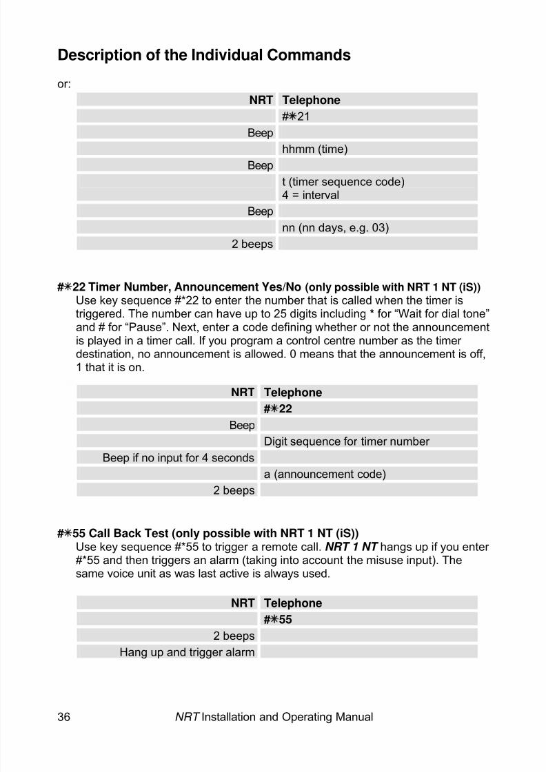
# 22 Timer Number, Announcement Yes/No (only possible with NRT 1 NT (iS)) Use key sequence #*22 to enter the number that is called when the timer istriggered. The number can have up to 25 digits including * for “Wait for dial tone”and # for “Pause”. Next, enter a code defining whether or not the announcementis played in a timer call. If you program a control centre number as the timer destination, no announcement is allowed. 0 means that the announcement is off,1 that it is on.
NRT Telephone
# 22Beep
Digit sequence for timer number Beep if no input for 4 seconds
a (announcement code)2 beeps
# 55 Call Back Test (only possible with NRT 1 NT (iS))Use key sequence #*55 to trigger a remote call. NRT 1 NT hangs up if you enter #*55 and then triggers an alarm (taking into account the misuse input). Thesame voice unit as was last active is always used.
NRT Telephone# 55
2 beepsHang up and trigger alarm
8/6/2019 Bedienungsanleitung NRT en Stand 10-04-2008
http://slidepdf.com/reader/full/bedienungsanleitung-nrt-en-stand-10-04-2008 39/52
NRT Installation and Operating Manual 37
Description of the Individual Commands
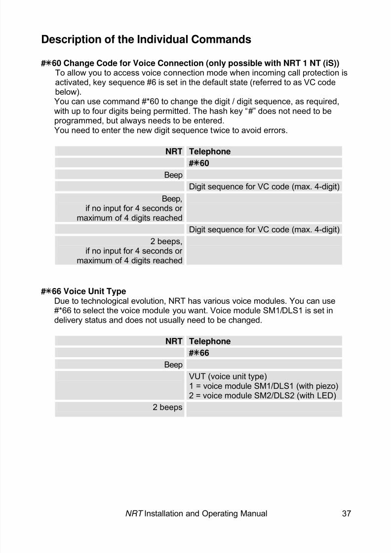
# 60 Change Code for Voice Connection (only possible with NRT 1 NT (iS))To allow you to access voice connection mode when incoming call protection isactivated, key sequence #6 is set in the default state (referred to as VC codebelow).You can use command #*60 to change the digit / digit sequence, as required,with up to four digits being permitted. The hash key “#” does not need to beprogrammed, but always needs to be entered.You need to enter the new digit sequence twice to avoid errors.
NRT Telephone# 60
BeepDigit sequence for VC code (max. 4-digit)
Beep,if no input for 4 seconds or
maximum of 4 digits reached
Digit sequence for VC code (max. 4-digit)2 beeps,
if no input for 4 seconds or maximum of 4 digits reached
# 66 Voice Unit TypeDue to technological evolution, NRT has various voice modules. You can use#*66 to select the voice module you want. Voice module SM1/DLS1 is set indelivery status and does not usually need to be changed.
NRT Telephone# 66
BeepVUT (voice unit type)
1 = voice module SM1/DLS1 (with piezo)2 = voice module SM2/DLS2 (with LED)2 beeps
8/6/2019 Bedienungsanleitung NRT en Stand 10-04-2008
http://slidepdf.com/reader/full/bedienungsanleitung-nrt-en-stand-10-04-2008 40/52
NRT Installation and Operating Manual 38
Description of the Individual Commands
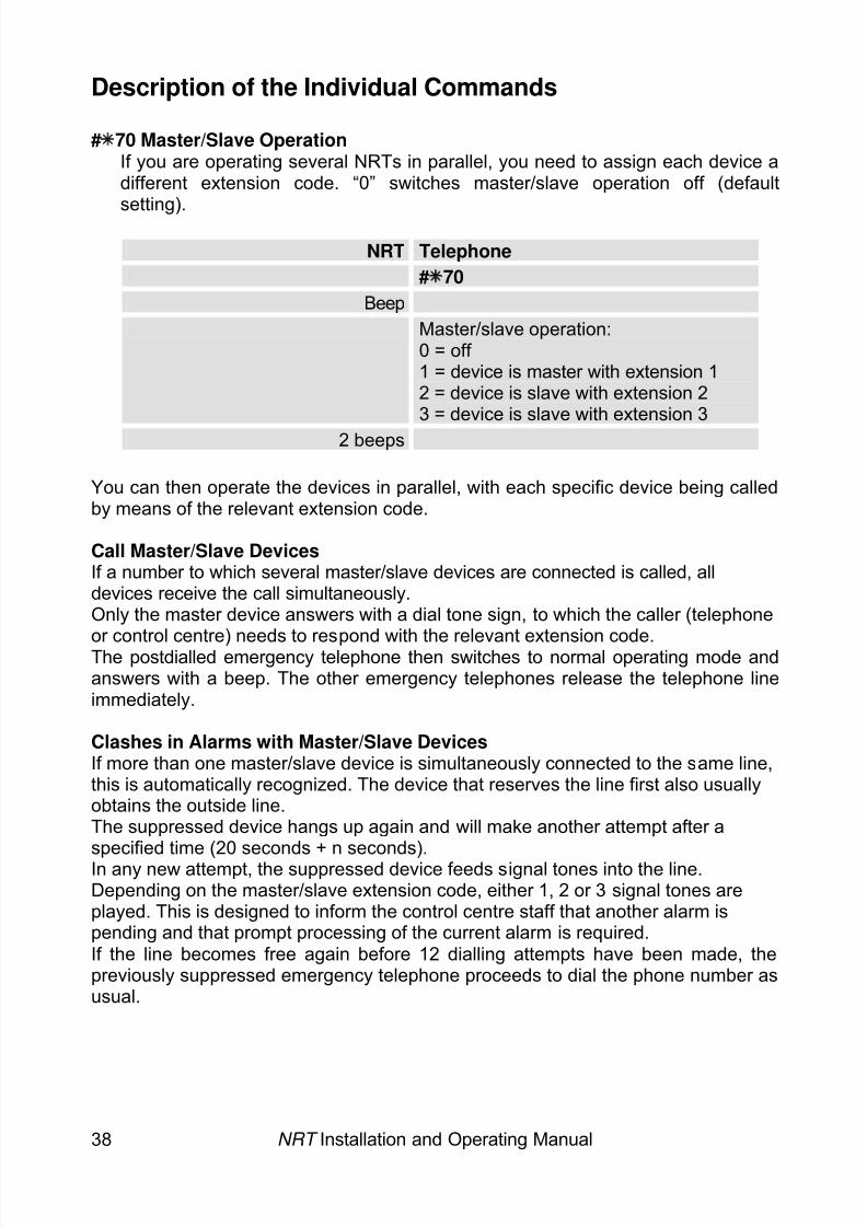
# 70 Master/Slave OperationIf you are operating several NRTs in parallel, you need to assign each device adifferent extension code. “0” switches master/slave operation off (defaultsetting).
NRT Telephone# 70
BeepMaster/slave operation:0 = off 1 = device is master with extension 12 = device is slave with extension 23 = device is slave with extension 3
2 beeps
You can then operate the devices in parallel, with each specific device being calledby means of the relevant extension code.
Call Master/Slave DevicesIf a number to which several master/slave devices are connected is called, alldevices receive the call simultaneously.Only the master device answers with a dial tone sign, to which the caller (telephone
or control centre) needs to respond with the relevant extension code.The postdialled emergency telephone then switches to normal operating mode andanswers with a beep. The other emergency telephones release the telephone lineimmediately.
Clashes in Alarms with Master/Slave DevicesIf more than one master/slave device is simultaneously connected to the same line,this is automatically recognized. The device that reserves the line first also usuallyobtains the outside line.The suppressed device hangs up again and will make another attempt after aspecified time (20 seconds + n seconds).In any new attempt, the suppressed device feeds signal tones into the line.Depending on the master/slave extension code, either 1, 2 or 3 signal tones areplayed. This is designed to inform the control centre staff that another alarm ispending and that prompt processing of the current alarm is required.If the line becomes free again before 12 dialling attempts have been made, thepreviously suppressed emergency telephone proceeds to dial the phone number asusual.
8/6/2019 Bedienungsanleitung NRT en Stand 10-04-2008
http://slidepdf.com/reader/full/bedienungsanleitung-nrt-en-stand-10-04-2008 41/52
NRT Installation and Operating Manual 39
Description of the Individual Commands
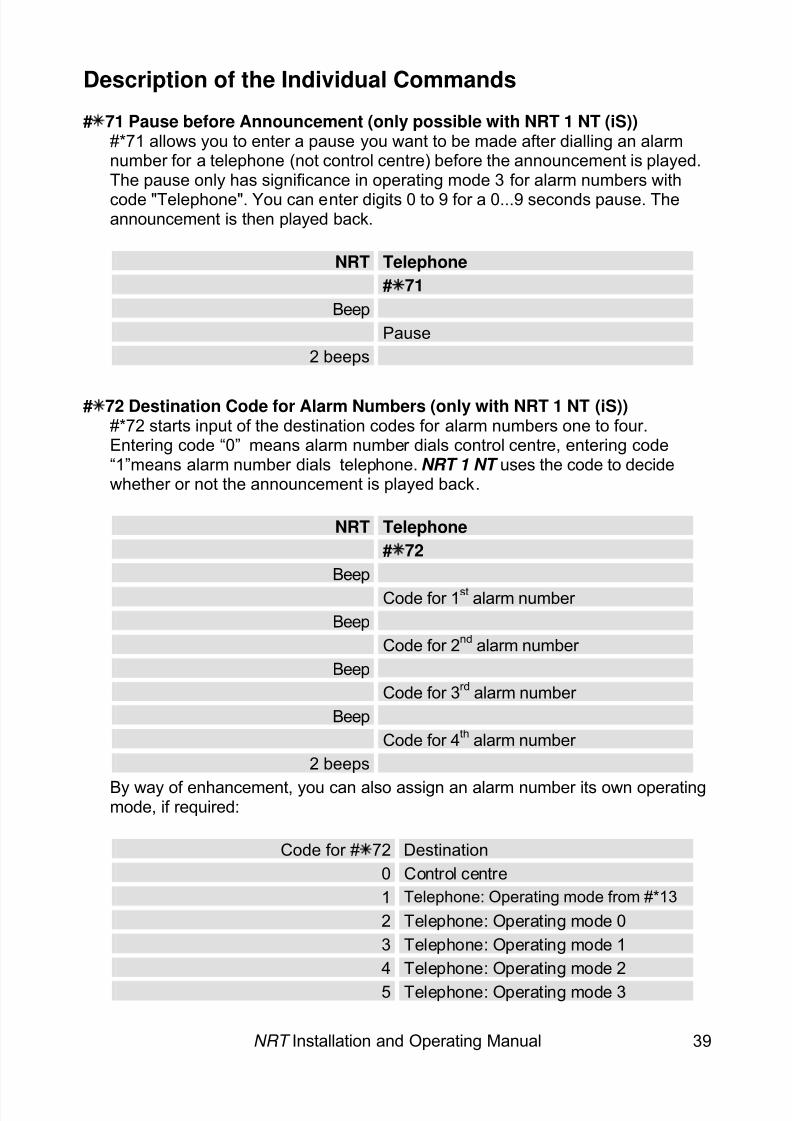
# 71 Pause before Announcement (only possible with NRT 1 NT (iS))#*71 allows you to enter a pause you want to be made after dialling an alarmnumber for a telephone (not control centre) before the announcement is played.The pause only has significance in operating mode 3 for alarm numbers withcode "Telephone". You can enter digits 0 to 9 for a 0...9 seconds pause. Theannouncement is then played back.
NRT Telephone# 71
BeepPause
2 beeps
# 72 Destination Code for Alarm Numbers (only with NRT 1 NT (iS))#*72 starts input of the destination codes for alarm numbers one to four.Entering code “0” means alarm number dials control centre, entering code“1”means alarm number dials telephone. NRT 1 NT uses the code to decide whether or not the announcement is played back.
NRT Telephone# 72
BeepCode for 1st alarm number
BeepCode for 2nd alarm number
BeepCode for 3 rd alarm number
BeepCode for 4 th alarm number
2 beeps
By way of enhancement, you can also assign an alarm number its own operatingmode, if required:
Code for # 72 Destination0 Control centre1 Telephone: Operating mode from #*132 Telephone: Operating mode 03 Telephone: Operating mode 14 Telephone: Operating mode 25 Telephone: Operating mode 3
8/6/2019 Bedienungsanleitung NRT en Stand 10-04-2008
http://slidepdf.com/reader/full/bedienungsanleitung-nrt-en-stand-10-04-2008 42/52
NRT Installation and Operating Manual 40
Description of the Individual Commands
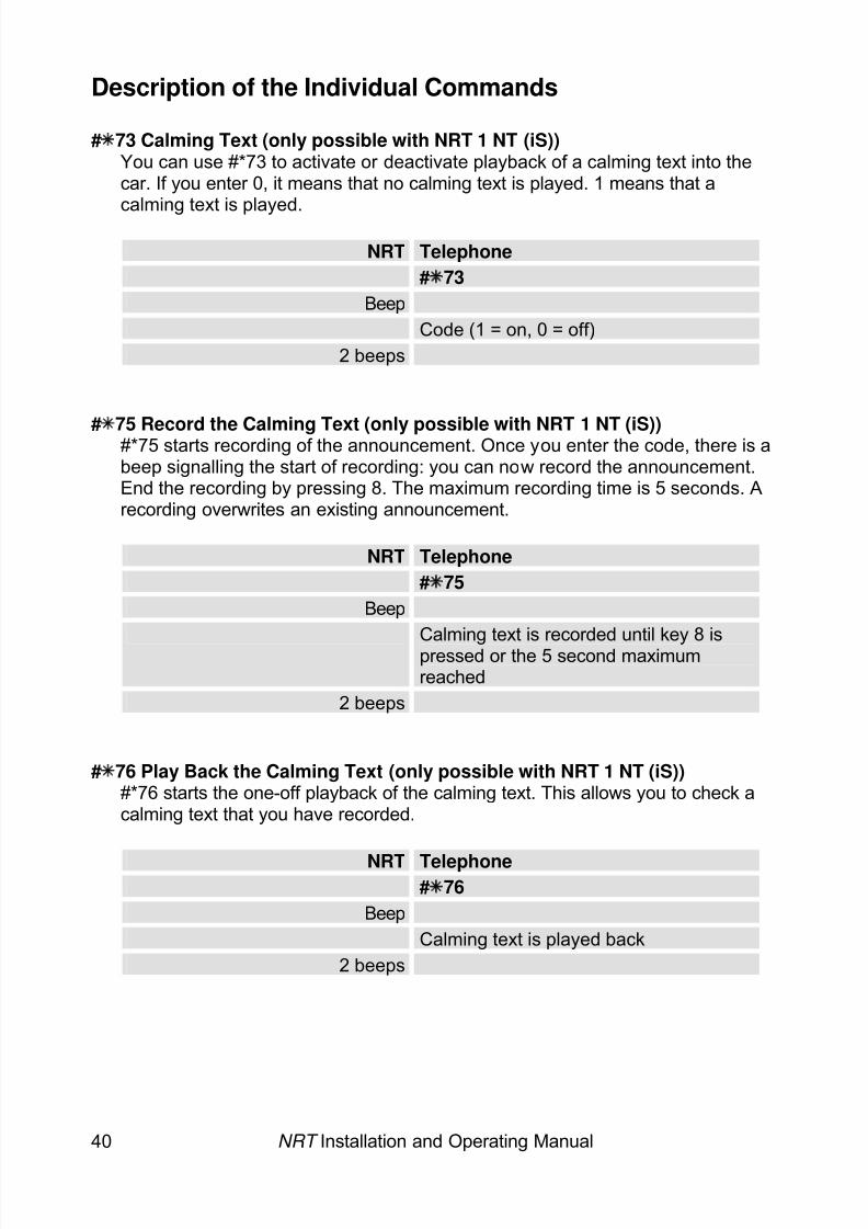
# 73 Calming Text (only possible with NRT 1 NT (iS))You can use #*73 to activate or deactivate playback of a calming text into thecar. If you enter 0, it means that no calming text is played. 1 means that acalming text is played.
NRT Telephone# 73
BeepCode (1 = on, 0 = off)
2 beeps
# 75 Record the Calming Text (only possible with NRT 1 NT (iS))#*75 starts recording of the announcement. Once you enter the code, there is abeep signalling the start of recording: you can now record the announcement.End the recording by pressing 8. The maximum recording time is 5 seconds. Arecording overwrites an existing announcement.
NRT Telephone# 75
BeepCalming text is recorded until key 8 ispressed or the 5 second maximumreached
2 beeps
# 76 Play Back the Calming Text (only possible with NRT 1 NT (iS))#*76 starts the one-off playback of the calming text. This allows you to check acalming text that you have recorded.
NRT Telephone# 76
BeepCalming text is played back
2 beeps
8/6/2019 Bedienungsanleitung NRT en Stand 10-04-2008
http://slidepdf.com/reader/full/bedienungsanleitung-nrt-en-stand-10-04-2008 43/52
NRT Installation and Operating Manual 41
Description of the Individual Commands
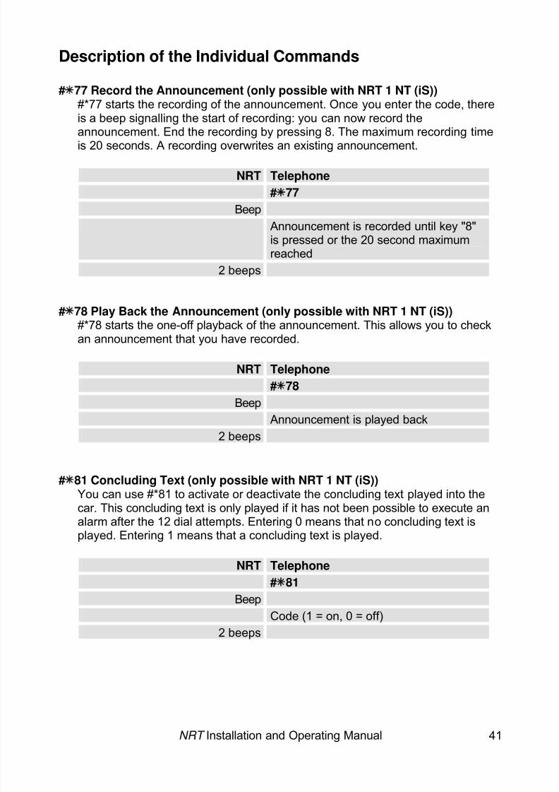
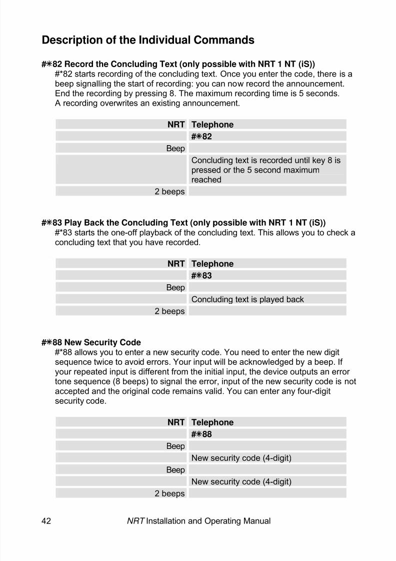
# 77 Record the Announcement (only possible with NRT 1 NT (iS))#*77 starts the recording of the announcement. Once you enter the code, thereis a beep signalling the start of recording: you can now record theannouncement. End the recording by pressing 8. The maximum recording timeis 20 seconds. A recording overwrites an existing announcement.
NRT Telephone# 77
BeepAnnouncement is recorded until key "8"is pressed or the 20 second maximumreached
2 beeps
# 78 Play Back the Announcement (only possible with NRT 1 NT (iS))#*78 starts the one-off playback of the announcement. This allows you to checkan announcement that you have recorded.
NRT Telephone# 78
BeepAnnouncement is played back
2 beeps
# 81 Concluding Text (only possible with NRT 1 NT (iS))You can use #*81 to activate or deactivate the concluding text played into thecar. This concluding text is only played if it has not been possible to execute analarm after the 12 dial attempts. Entering 0 means that no concluding text isplayed. Entering 1 means that a concluding text is played.
NRT Telephone# 81
BeepCode (1 = on, 0 = off)
2 beeps
8/6/2019 Bedienungsanleitung NRT en Stand 10-04-2008
http://slidepdf.com/reader/full/bedienungsanleitung-nrt-en-stand-10-04-2008 44/52
8/6/2019 Bedienungsanleitung NRT en Stand 10-04-2008
http://slidepdf.com/reader/full/bedienungsanleitung-nrt-en-stand-10-04-2008 45/52
NRT Installation and Operating Manual 43
Description of the Individual Commands
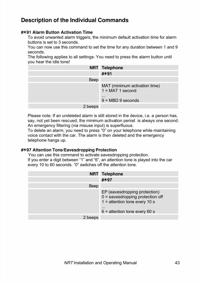
# 91 Alarm Button Activation TimeTo avoid unwanted alarm triggers, the minimum default activation time for alarmbuttons is set to 3 seconds.You can now use this command to set the time for any duration between 1 and 9seconds.The following applies to all settings: You need to press the alarm button untilyou hear the idle tone!
NRT Telephone# 91
BeepMAT (minimum activation time)1 = MAT 1 second...9 = MBD 9 seconds
2 beeps
Please note: If an undeleted alarm is still stored in the device, i.e. a person has,say, not yet been rescued, the minimum activation period is always one second.An emergency filtering (via misuse input) is superfluous.To delete an alarm, you need to press “0” on your telephone while maintainingvoice contact with the car. The alarm is then deleted and the emergencytelephone hangs up.
# 97 Attention Tone/Eavesdropping ProtectionYou can use this command to activate eavesdropping protection.If you enter a digit between “1” and “6”, an attention tone is played into the car every 10 to 60 seconds. “0” switches off the attention tone.
NRT Telephone# 97
BeepEP (eavesdropping protection)
0 = eavesdropping protection off 1 = attention tone every 10 s...6 = attention tone every 60 s
2 beeps
8/6/2019 Bedienungsanleitung NRT en Stand 10-04-2008
http://slidepdf.com/reader/full/bedienungsanleitung-nrt-en-stand-10-04-2008 46/52
NRT Installation and Operating Manual 44
Description of the Individual Commands
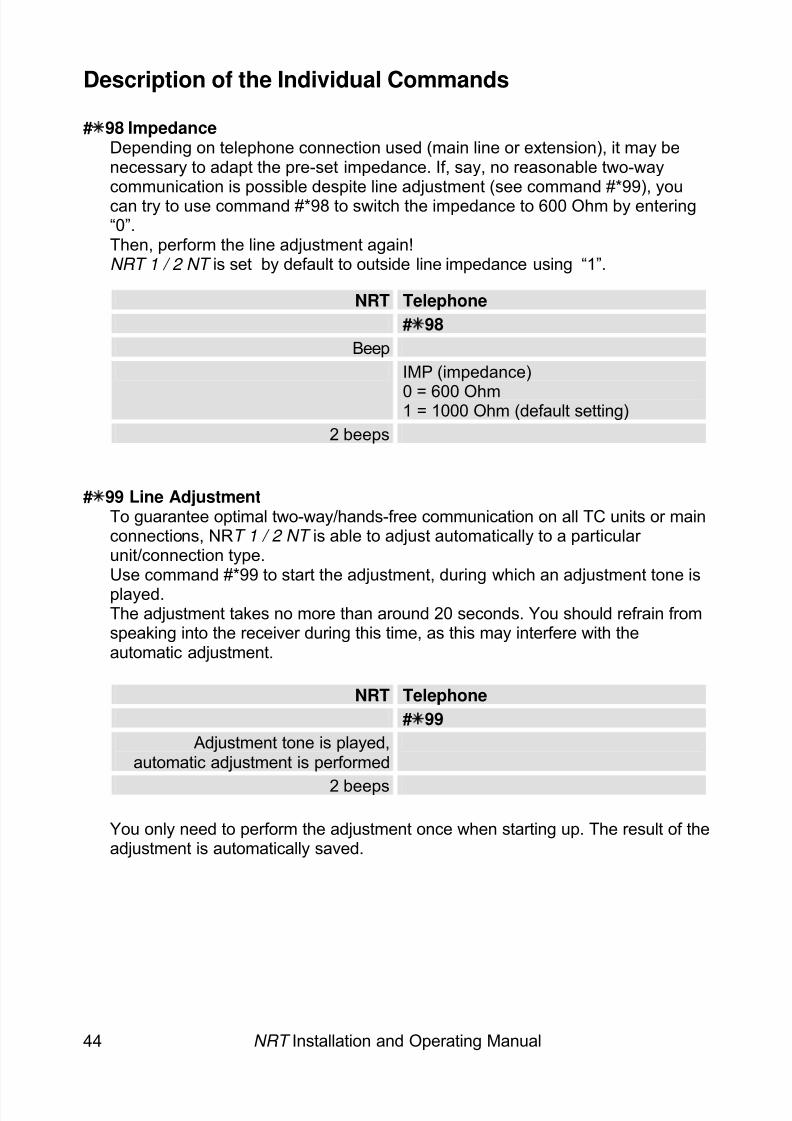
# 98 ImpedanceDepending on telephone connection used (main line or extension), it may benecessary to adapt the pre-set impedance. If, say, no reasonable two-waycommunication is possible despite line adjustment (see command #*99), youcan try to use command #*98 to switch the impedance to 600 Ohm by entering“0”.Then, perform the line adjustment again!NRT 1 / 2 NT is set by default to outside line impedance using “1”.
NRT Telephone# 98
BeepIMP (impedance)
0 = 600 Ohm1 = 1000 Ohm (default setting)2 beeps
# 99 Line AdjustmentTo guarantee optimal two-way/hands-free communication on all TC units or mainconnections, NR T 1 / 2 NT is able to adjust automatically to a particular unit/connection type.Use command #*99 to start the adjustment, during which an adjustment tone isplayed.The adjustment takes no more than around 20 seconds. You should refrain fromspeaking into the receiver during this time, as this may interfere with theautomatic adjustment.
NRT Telephone# 99
Adjustment tone is played,automatic adjustment is performed
2 beeps
You only need to perform the adjustment once when starting up. The result of theadjustment is automatically saved.
8/6/2019 Bedienungsanleitung NRT en Stand 10-04-2008
http://slidepdf.com/reader/full/bedienungsanleitung-nrt-en-stand-10-04-2008 47/52
NRT Installation and Operating Manual 45
Example of How to Program Using the Telephone
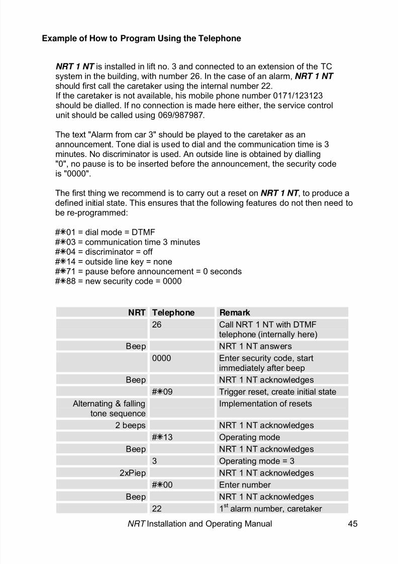
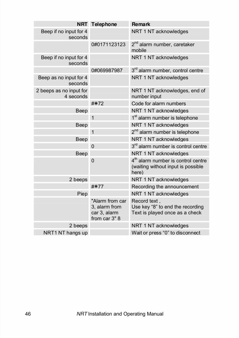
NRT 1 NT is installed in lift no. 3 and connected to an extension of the TCsystem in the building, with number 26. In the case of an alarm, NRT 1 NT should first call the caretaker using the internal number 22.
If the caretaker is not available, his mobile phone number 0171/123123should be dialled. If no connection is made here either, the service controlunit should be called using 069/987987.
The text "Alarm from car 3" should be played to the caretaker as anannouncement. Tone dial is used to dial and the communication time is 3minutes. No discriminator is used. An outside line is obtained by dialling"0", no pause is to be inserted before the announcement, the security codeis "0000".
The first thing we recommend is to carry out a reset on NRT 1 NT , to produce adefined initial state. This ensures that the following features do not then need tobe re-programmed:
# 01 = dial mode = DTMF# 03 = communication time 3 minutes# 04 = discriminator = off # 14 = outside line key = none# 71 = pause before announcement = 0 seconds# 88 = new security code = 0000
NRT Telephone Remark26 Call NRT 1 NT with DTMF
telephone (internally here)Beep NRT 1 NT answers
0000 Enter security code, startimmediately after beep
Beep NRT 1 NT acknowledges
# 09 Trigger reset, create initial stateAlternating & fallingtone sequence
Implementation of resets
2 beeps NRT 1 NT acknowledges# 13 Operating mode
Beep NRT 1 NT acknowledges3 Operating mode = 3
2xPiep NRT 1 NT acknowledges# 00 Enter number
Beep NRT 1 NT acknowledges22 1st alarm number, caretaker
8/6/2019 Bedienungsanleitung NRT en Stand 10-04-2008
http://slidepdf.com/reader/full/bedienungsanleitung-nrt-en-stand-10-04-2008 48/52
8/6/2019 Bedienungsanleitung NRT en Stand 10-04-2008
http://slidepdf.com/reader/full/bedienungsanleitung-nrt-en-stand-10-04-2008 49/52
Battery Replacement
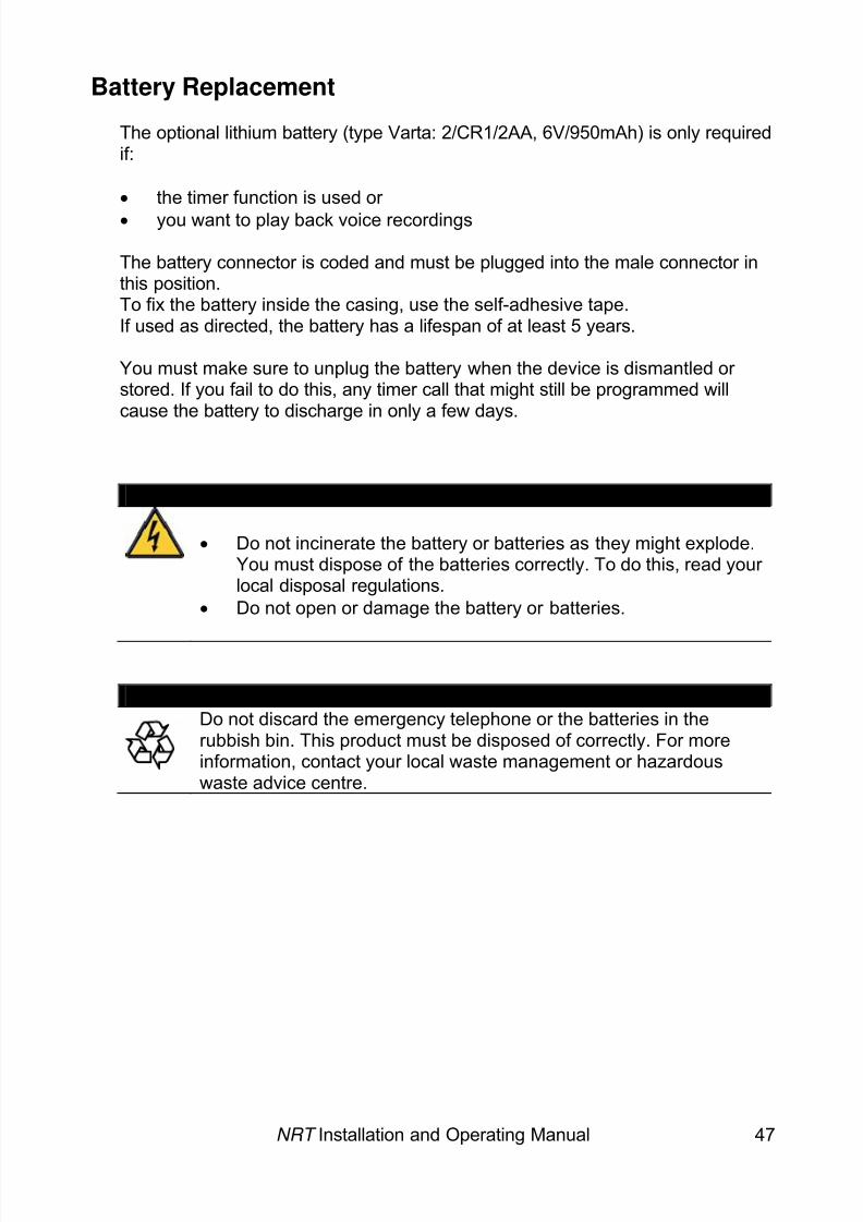
The optional lithium battery (type Varta: 2/CR1/2AA, 6V/950mAh) is only requiredif:
• the timer function is used or • you want to play back voice recordings
The battery connector is coded and must be plugged into the male connector inthis position.To fix the battery inside the casing, use the self-adhesive tape.If used as directed, the battery has a lifespan of at least 5 years.
You must make sure to unplug the battery when the device is dismantled or stored. If you fail to do this, any timer call that might still be programmed willcause the battery to discharge in only a few days.
CAUTION
• Do not incinerate the battery or batteries as they might explode.You must dispose of the batteries correctly. To do this, read your local disposal regulations.
• Do not open or damage the battery or batteries.
CAUTIONDo not discard the emergency telephone or the batteries in therubbish bin. This product must be disposed of correctly. For moreinformation, contact your local waste management or hazardouswaste advice centre.
NRT Installation and Operating Manual 47
8/6/2019 Bedienungsanleitung NRT en Stand 10-04-2008
http://slidepdf.com/reader/full/bedienungsanleitung-nrt-en-stand-10-04-2008 50/52
NRT Installation and Operating Manual 48
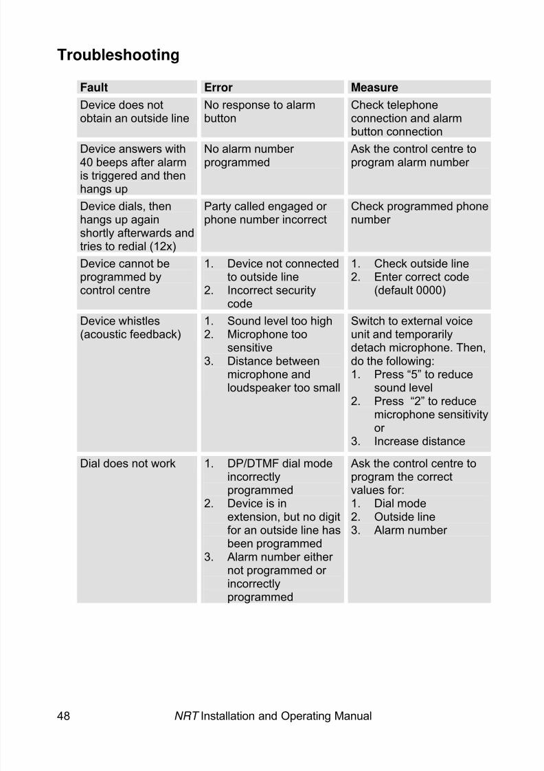
Troubleshooting
Fault Error MeasureDevice does notobtain an outside line
No response to alarmbutton
Check telephoneconnection and alarm
button connectionDevice answers with40 beeps after alarmis triggered and thenhangs up
No alarm number programmed
Ask the control centre toprogram alarm number
Device dials, thenhangs up againshortly afterwards andtries to redial (12x)
Party called engaged or phone number incorrect
Check programmed phonenumber
Device cannot beprogrammed bycontrol centre
1. Device not connectedto outside line
2. Incorrect securitycode
1. Check outside line2. Enter correct code
(default 0000)
Device whistles(acoustic feedback)
1. Sound level too high2. Microphone too
sensitive3. Distance between
microphone andloudspeaker too small
Switch to external voiceunit and temporarilydetach microphone. Then,do the following:1. Press “5” to reduce
sound level
2. Press “2” to reducemicrophone sensitivityor
3. Increase distance
Dial does not work 1. DP/DTMF dial modeincorrectlyprogrammed
2. Device is inextension, but no digitfor an outside line hasbeen programmed
3. Alarm number either not programmed or incorrectlyprogrammed
Ask the control centre toprogram the correctvalues for:1. Dial mode2. Outside line3. Alarm number
8/6/2019 Bedienungsanleitung NRT en Stand 10-04-2008
http://slidepdf.com/reader/full/bedienungsanleitung-nrt-en-stand-10-04-2008 51/52
NRT Installation and Operating Manual 49
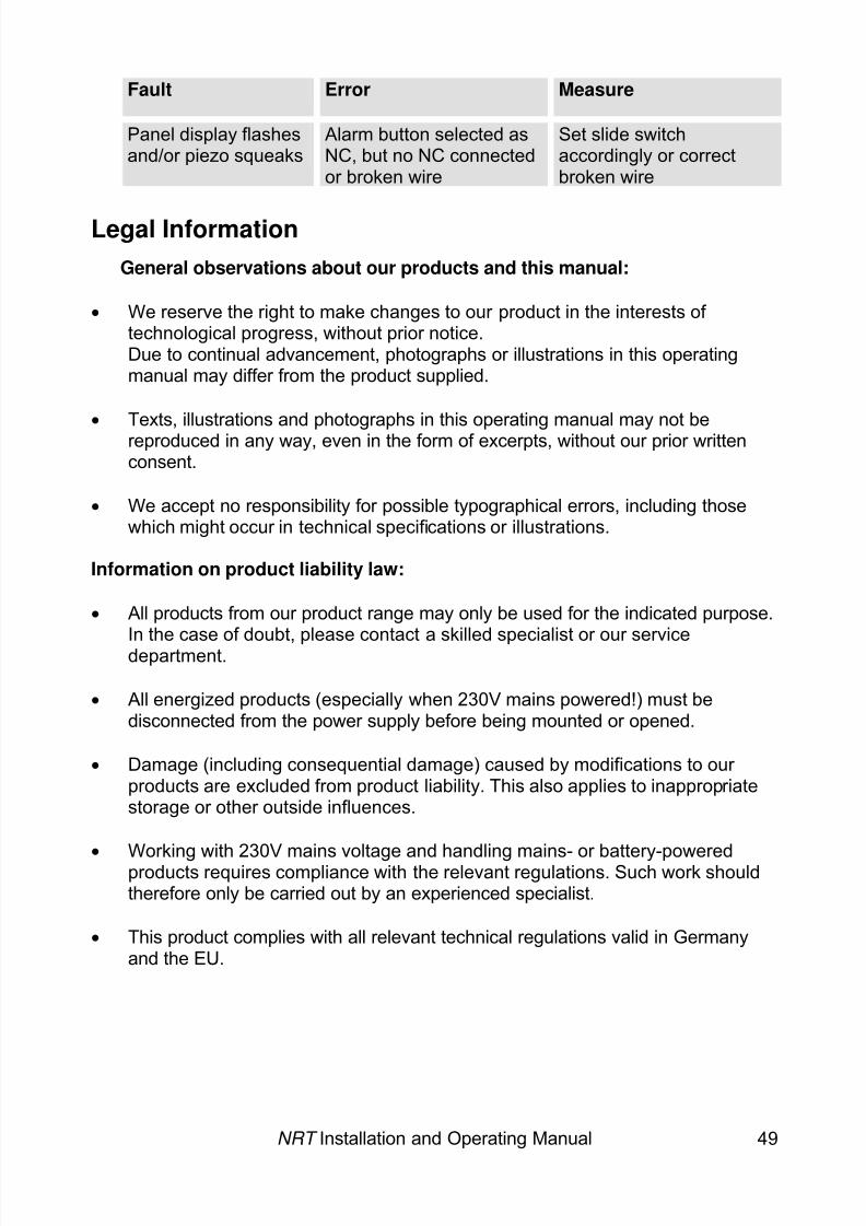
Fault Error Measure
Panel display flashesand/or piezo squeaks
Alarm button selected asNC, but no NC connectedor broken wire
Set slide switchaccordingly or correctbroken wire
Legal InformationGeneral observations about our products and this manual:
• We reserve the right to make changes to our product in the interests of technological progress, without prior notice.Due to continual advancement, photographs or illustrations in this operatingmanual may differ from the product supplied.
• Texts, illustrations and photographs in this operating manual may not bereproduced in any way, even in the form of excerpts, without our prior writtenconsent.
• We accept no responsibility for possible typographical errors, including thosewhich might occur in technical specifications or illustrations.
Information on product liability law:
• All products from our product range may only be used for the indicated purpose.In the case of doubt, please contact a skilled specialist or our servicedepartment.
• All energized products (especially when 230V mains powered!) must bedisconnected from the power supply before being mounted or opened.
• Damage (including consequential damage) caused by modifications to our products are excluded from product liability. This also applies to inappropriatestorage or other outside influences.
•
Working with 230V mains voltage and handling mains- or battery-poweredproducts requires compliance with the relevant regulations. Such work shouldtherefore only be carried out by an experienced specialist.
• This product complies with all relevant technical regulations valid in Germanyand the EU.

8/6/2019 Bedienungsanleitung NRT en Stand 10-04-2008
http://slidepdf.com/reader/full/bedienungsanleitung-nrt-en-stand-10-04-2008 52/52
Art. Nr. 11 1407
As of: Telegärtner Elektronik GmbH10th April 2008 Hofäckerstrasse 18 74564 Crailsheim
Tel : +49 7951 / 488 0


