Beck group - A YEAR IN SCANNING: BEST PRACTICES FOR LARGE MULTIPHASED PROJECTS
44
A YEAR IN SCANNING: BEST PRACTICES FOR LARGE MULTI- PHASED PROJECTS Duke University Athletic Complex
-
Upload
greg-dolphin -
Category
Engineering
-
view
31 -
download
4
Transcript of Beck group - A YEAR IN SCANNING: BEST PRACTICES FOR LARGE MULTIPHASED PROJECTS

A YEAR IN SCANNING: BEST PRACTICES FOR LARGE MULTI-PHASED PROJECTS Duke University Athletic Complex

Terry Henry is a seventeen year veteran of surveying and has been laser scanning for the past three years. He performs all laser scan duties for The Beck Group, a construction and architectural design firm. You can contact Terry at [email protected].
Brendan Nichols studied architecture at Georgia Tech. He joined The Beck Group in January 2014. He specializes in the scan-to-BIM process. You can contact Brendan at [email protected] Twitter: @BrendanANichols
Presenter
Presentation Notes
What office we are in
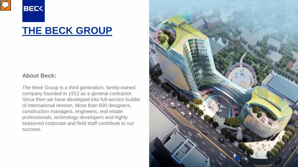
THE BECK GROUP
The Beck Group is a third generation, family-owned company founded in 1912 as a general contractor. Since then we have developed into full-service builder of international renown. More than 600 designers, construction managers, engineers, real estate professionals, technology developers and highly seasoned corporate and field staff contribute to our success.
About Beck:
Presenter
Presentation Notes
The Beck group is a large design build company. We have offices in Dallas, Fort Worth, Austin, Denver, Tampa, and Atlanta Sometimes we get to do really cool work like this church in Korea

THE VIRTUAL BUILDING GROUP Mission: Develop people and processes to revolutionize how we deliver projects.
Vision: Create an environment where people passionate about integration and innovation are charged with finding better ways to do our jobs. Goals: Identify and test opportunities for process
innovation Develop and execute new processes and tools to
improve our company’s profitability Rapidly implement proved process changes
through training and project level support Make Beck synonymous with AEC research,
development, and process change
Presenter
Presentation Notes
We don’t actually expect you to read all of this, but what you should know is That we are like the VDC department at other contractors Except we also do work for external clients Typically we are doing laser scanning or modeling for any number of different purposes We own and use a Leica P20 But in general our goal is to be the best and most innovative group/company in the industry

Duke University hired Beck to provide design and construction services for a number of athletic buildings on their campus. Projects are all renovations, expansions, or new construction. All require a thorough understanding of the existing conditions. -Cameron Indoor Stadium -Murray-Scott Building -Wallace Wade Stadium
Presenter
Presentation Notes
Our project is broken into three main phases with roughly 6 months time between each phase. Phase 1 is Wallace Wade Stadium- a collegiate football field Phase 2 is the Murray-Scott building and Cameron indoor Stadium’s southern façade- these are a training facility and historic basketball stadium Phase 3 is the entire Cameron indoor stadium- with the intent of MEP coordination

PHASE 1: WALLACE WADE STADIUM AND SURROUNDING STRUCTURES

Phase 1: Wallace Wade Stadium and Surrounding Structures Planned Design and Construction: -Field Lowering -Increase Lower level Seating -New Press Tower, Box Seating, and Lower Level Seating -Renovate and Improve Concourse -Seating Replacement and Upgrades -New Scoreboard -New Broadcast Infrastructure Modeling Requirements: -Wallace Wade Stadium Seating -Surrounding Concourse -Lower Level Field and Wall

SOW: Wallace Wade Stadium -New Press Tower
-Field Lowering -Updated Concourse
Early Conceptual Design Sketch
Presenter
Presentation Notes
This slide we can talk about how we often scan before the conceptual design is even finished. This requires us to be more flexible/thorough in the field. The information captured can be used for different purposes than originally expected. Areas that were not originally seen as critical can become critical later in the process. Make jokes about the football team finally getting good and needing a better, larger facility

Scanning Plan: Phase 1
Scanning plan produced for client and included in contract. -142 estimated scan locations -4 days scheduled for scanning -Large distances between scan locations because of the openness of the site -Clear shots to survey points in football field
Presenter
Presentation Notes
This slide we really could talk about what we knew was going to be staying and what was going to be demoed. This let us know what areas would be critical in out scanning. Yoh Tower demoed, field lowered, stadium stays, concourse changed dramatically. This leads to the scanning job being entirely outdoors with little to block the scanner at longer shots So all these factors lead to the job being “surveyed” Our State Plane control points were given to us by Duke’s 3rd party surveyor

Scanning Results: Phase 1
Presenter
Presentation Notes
These are the scanning results

Scanning Results: Phase 1
Presenter
Presentation Notes
Here is the existing press tower, which is slated for demolition ???

Scanning Results: Phase 1
-123 actual scan locations -Completed in 4 days
Presenter
Presentation Notes
We need to add information about how many days we were in the field

Complete Existing Conditions Model
Presenter
Presentation Notes
Varying levels of detail based on how important the structures actually were (if they were demoed or not)

Completed Design Model
Presenter
Presentation Notes
This model and image shows that the scanning and existing conditions model are at the center of the final design. Almost every new structure ties into what was scanned.

Construction Jan 21
Presenter
Presentation Notes
Construction has begun. This year we will be completing the field lowering and lower level seating (and???)
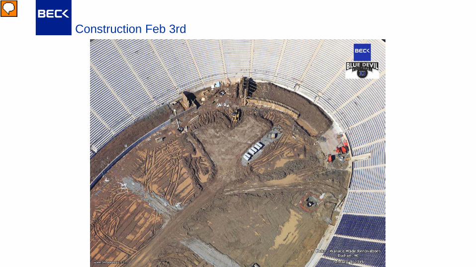
Construction Feb 3rd
Presenter
Presentation Notes
Here you can see the formwork for the lower level seating and some of the new utility work being done

PHASE 2: MURRAY-SCOTT EXTERIOR & CAMERON SOUTH LOBBY/ FACADE

Phase 2: Murray-Scott Exterior & Cameron South Lobby and Facade Planned Design and Construction: -Major Addition to North Side of Murray-Scott -Major Addition Attached to South Side of Cameron Indoor Stadium -Landscaping and Site Improvements Modeling Requirements: -Exterior of Murray-Scott Building -South Façade of Cameron Indoor -Southern Rooms and Lobbies of Cameron Indoor

SOW: Cameron Indoor Stadium
Presenter
Presentation Notes
This is the southern façade of Cameron Indoor stadium. For Duke fans, this façade is holy. Was originally constructed in 1949. Parts of the façade are 14” solid stone. It was built like a castle. The new design calls for a major renovation to be attached to this façade, and some interior renovations. We needed to understand every detail on this façade and every room on the other side of this wall, in order to properly build a building that would attach to it.

SOW: Murray-Scott Building
Presenter
Presentation Notes
The Murray building was built in 1985. The EIFS façade hasn’t held up well, and the building generally isn’t large enough for the needs of the university. The design called for a major addition to this building. The new design was changing quickly and it was determined that the entire exterior of the building need to be scanned.

Scanning Plan: Phase 2
Scanning plan produced for client and included in contract. -Estimated 50 scans -2 days scheduled -Interior and exterior scanning
Presenter
Presentation Notes
Only two survey points to tie into because of the site’s geometry The rest of the survey points were in the field and not visible from this area We executed the scan and registered all the data

Survey Control Bust
Phase 1 scan data
Phase 2 scan data
Presenter
Presentation Notes
During modeling, we noticed a major bust when bringing the phase 1 and phase 2 together on the same coordinate system. This was one of the worst locations of the bust in the entire project. This is on the Southern corner of the Murray building.

Survey Control Bust Explained
We uncovered the two survey coordinates we used in phase two were slightly off
However, these errors caused a rotational error
Because these points were far from the building, the error scaled with distance, causing a much greater local error
Presenter
Presentation Notes
After re-registering the all of phase 2 using cloud-to-cloud constraints, we uncovered the problem Our two survey points for phase 2 which were okay by civil standards with a survey GPS, caused a bigger problem The two points were fairly close to eachother and much farther from out building. This small rotational error scales with the distance to the building. The further away from these points we were the greater the error was.

Survey Control Bust Fixed
After re-registering the all of phase 2 using cloud-to-cloud constraints to phase 1
Presenter
Presentation Notes
Method for fix- Chose control points in center of the field that we felt more confident about, Re-tied scans to central field control points Shape of the stadium blocked visibility between interior and exterior scan locations, So, we manually defined targets on surrounding buildings and distinct features that were visible from most of the site. In particular we used the YOH tower and the upper face of Cameron

Scanning Results: Phase 2
60 Actual Scan locations Completed in two days
Presenter
Presentation Notes
We could briefly mention how the weather was pretty bad and took out most of one of our days. Planning for that kind of problem should be standard on exterior jobs

Complete Existing Conditions Model: Cameron Indoor South
Presenter
Presentation Notes
Here’s our as-built model overlaid with the pointcloud

Complete Existing Conditions Model: Cameron Indoor South
Presenter
Presentation Notes
Another overlay of the same thing

Complete Existing Conditions Model: Cameron Indoor South
Presenter
Presentation Notes
Here you can see some of the detail put into the model. Including accurate stone window frames, and interior molding and casework

New Design Model
Presenter
Presentation Notes
Here is the new design model. Using what we provided the new addition is added directly to the existing facade
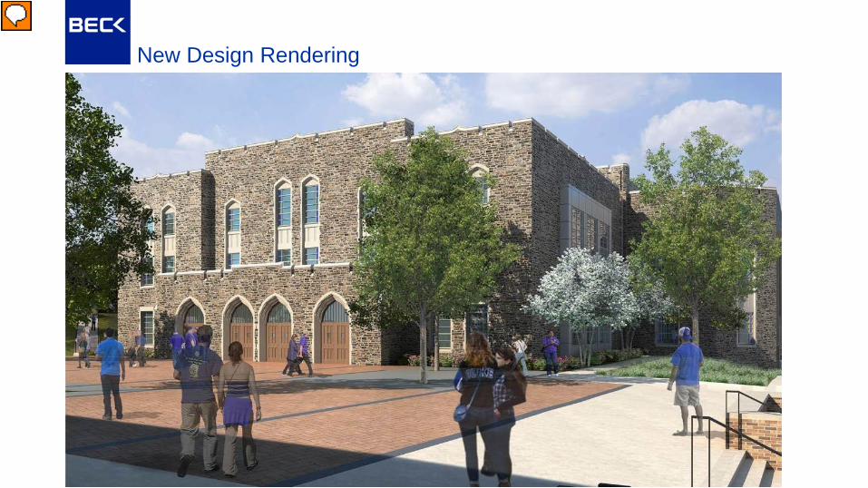
New Design Rendering
Presenter
Presentation Notes
And here’s a rendering of the new design

PHASE 3: CAMERON INDOOR FIRE SPRINKLER SYSTEM

Phase 3: Cameron Indoor Fire Sprinkler System Planned Design and Construction: -Potential to Add a New Fire Sprinkler System to the Interior Spaces of Cameron Indoor Stadium Modeling Requirements: -Cameron Exterior Facade -Generic Interior Rooms and Spaces -All Visible MEP Systems for 3D Coordination -Visible Structure that may Conflict with Fire Protection

SOW: Cameron Fire Sprinkler System
Purpose: New design to existing building required at the very least a fire wall between old and new. However, the alternative was to add fire protection to the existing building instead -Existing Building -New Addition
Presenter
Presentation Notes
As design for the new Cameron addition was progressing, the design team had run into a building code problem. Basically, the existing building had been built to older fire codes, and the new addition needed a fire wall between the new and old. To make the existing wall a firewall would have been expensive and difficult. The other option was to add a fire-sprinkler system to the existing building to bring it up to modern codes. This was more expensive but provided greater value to the owner.

Cameron Interior Conditions
Presenter
Presentation Notes
This was one of the few times we’ve actually had existing scans before we estimated the job. We knew the entire concourse had extremely dense overhead MEP systems. We were hired to capture and model all visible MEP systems over 2” in diameter for 3D coordination with the FP subcontractor. All visible structure had to be captured and modeled. Interior walls and partitions had to be captured and modeled at a low level of detail

Cameron Fire Sprinkler System Scanning Plan Challenges:
Many small rooms and tight spaces Short turn-around for modeling
Scanning plan produced for client and included in contract. Estimated 233 Scans 4 “Nights” for scanning
Presenter
Presentation Notes
Discuss the challenges of “ins-and-outs”. Makes estimates off of size or square footage incorrect. Mobility of the scanning crew. Doors, narrow hallways block scanner from targets. All new scanning had to be registered to previous scans without the use of control points Estimated over 250 scans Scanning to be completed in 4 days with all work completed at night Only 3 weeks after scanning for registration and modeling Required 2 scanners Entire job surveyed for quick processing time

Two Scanner Surveying Workflow Scenario:
Extremely tight schedule Mazelike interior scanning Two scanners
Presenter
Presentation Notes
Extremely tight scanning and MODELING schedule Need to be able to tie into eachother multiple times, crossing paths, etc. Two scanners that need to be on the same coordinate system
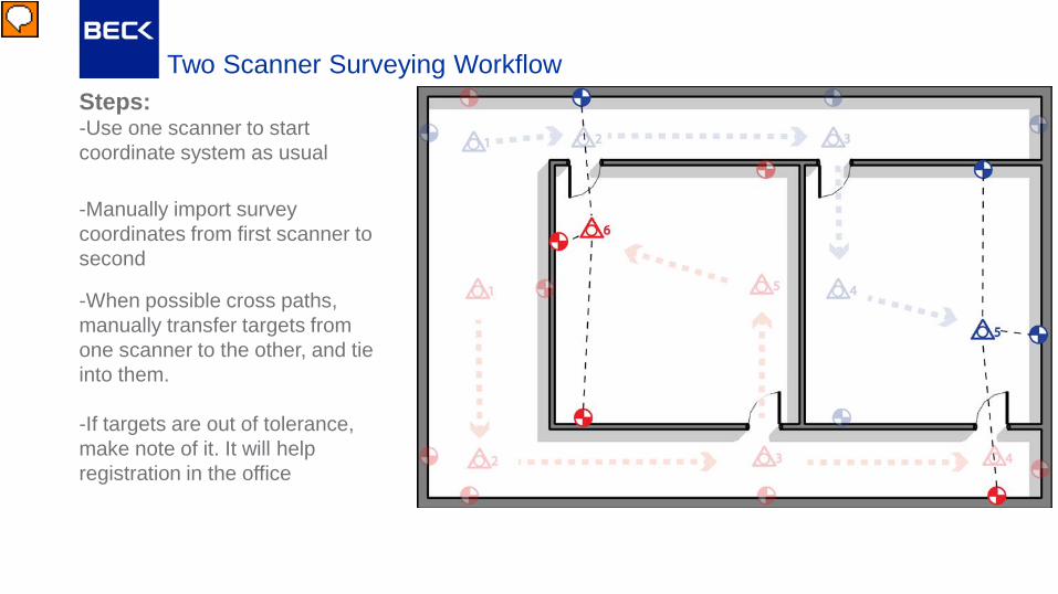
Two Scanner Surveying Workflow Steps:
-Use one scanner to start coordinate system as usual -Manually import survey coordinates from first scanner to second
-When possible cross paths, manually transfer targets from one scanner to the other, and tie into them. -If targets are out of tolerance, make note of it. It will help registration in the office
Presenter
Presentation Notes
2 clicks- Import survey coordinates from first scanner to second, then survey in new targets for your route, 3 clicks- After you have established both scanners on the same coordinate system, scan as usual. For this example here’s basic outline of our scanning route 4 clicks- here’s our route with targets placed as we would expect for these routes 6 clicks- Two special cases to show where you can “close the loop” on eachother’s targets. Basically use three targets to set the position of the scanner. Two of them being targets surveyed with the first scanner, and the third target coming from the other scanner. Manually transfer this third target, and check the “differential error” between the two scanners. Requires a lot of good planning and communication between the two scan “teams”. You need to understand where the other person is going and what areas they are capturing When you do this, you can import both scanners data and have it come in aligned. If you used the same naming conventions, you can auto add constraints between the two scanners This methodology is not recommended to get the tightest possible registration We used this methodology for all of phase 3

Scanning Results: Phase 3
249 Actual Scan locations Completed in 4 nights With two scanners
Presenter
Presentation Notes
Should note that because of our two scanner surveying workflow, we cut the in office registration time by 75% Which for this job, gave us two extra days for modeling

Scanning Results: Phase 3
Presenter
Presentation Notes
We could briefly mention how the weather was pretty bad and took out most of one of our days. Planning for that kind of problem should be standard on exterior jobs

Complete Existing Conditions Model: Cameron Fire Sprinkler System
Presenter
Presentation Notes
These are some of the scanning and modeling results. Here you can see the density of the MEP systems that we had to deal with. Conduit tree

Complete Existing Conditions Model: Cameron Fire Sprinkler System

Complete Existing Conditions Model: Cameron Fire Sprinkler System

Complete Design Model For Entire Site