Bearings, Couplings and Shaft Accessories Air-Preparation ...
97
Air-Preparation, Cylinders, Valves Air Motors and Accessories
Transcript of Bearings, Couplings and Shaft Accessories Air-Preparation ...
BOSTONGEAR
Bearings, Couplings and Shaft Accessories Air-Preparation,Cylinders, Valves
Air Motorsand Accessories
w w w . b o s t o n g e a r . c o m
Printed in USA
Boston Gear14 Hayward Street • Quincy, MA 02171617-328-3300 • Fax: 617-479-6238www.bostongear.com
P-1483-BG 50117 8/07
Warner ElectricElectromagnetic Clutches and Brakes - USA
South Beloit, IL815-389-3771
For application assistance:1-800-825-9050
Electromagnetic Clutches and Brakes - Europe
St Barthelemy d’Anjou, France+33 (0)2 41 21 24 24
For sales office:+33 (0)2 41 21 24 76
Precision Electric Coils andElectromagnetic Clutches and Brakes - USA
Columbia City, IN260-244-6183
Inertia Dynamics Spring Set Brakes; Power On andWrap Spring Clutch/Brakes
Torrington, CT860-482-4444
Matrix InternationalElectromagnetic Clutches and Brakes, Pressure Operated Clutches and Brakes
Brechin, Scotland+44 (0) 1356 602000
U.S.815-389-3771
Warner LinearLinear Actuators and Guideways - USA
Belvidere, IL815-547-1106
For application assistance:1-800-825-9050
TB Wood’sV-Belt Drives, Synchronous Drives,Flexible Couplings, VariableFrequency AC Drives
Chambersburg, PA717-264-7161
For assistance:1-888-829-6637Press #5 - Customer ServicePress #7 - Mechanical ApplicationsPress #8 - Electrinic Applications
Wichita Clutch and Industrial Clutch
Pneumatic and Oil ImmersedClutches and Brakes - USAWichita Falls, TX940-723-3400
Pneumatic Clutches and Brakes - Europe
Bedford, England+44 (0)1234 350311
Twiflex LimitedCaliper Brakes and Thrusters
Twickenham, England+44 (0) 20 8894 1161
Formsprag Clutch
Overrunning Clutches and Holdbacks
Warren, MI 48089586-758-5000
For application assistance:1-800-927-3262
Marland ClutchRoller Ramp and Sprag Type Overrunning Clutches and Backstops
Burr Ridge, IL630-455-1752
Stieber Clutch Overrunning Clutches and Holdbacks
Heidelberg, Germany+49 (0)6221 30 47 0
Boston GearEnclosed and Open Gearing, Electrical and Mechanical P.T. Components, Precision Gearheads, Precision CouplingsQuincy, MA617-328-3300
For customer service:1-888-999-9860
For application assistance:1-800-816-5608
Huco DynatorkPrecision Couplings and Air Motors
Hertford, England+44 (0) 1992 501900
Ameridrives CouplingsGear Couplings, Mill Spindles,Universal Joints
Erie, PA814-480-5000
Bibby TransmissionsDisc, Gear, Grid Couplings, Overload Clutches
Dewsbury, England+44 (0) 1924 460801
Nuttall Gear andDelroyd Worm GearWorm Gear and Helical Speed Reducers
Niagara Falls, NY716-298-4100
Saftek FrictionNon-asbestos Brake and ClutchMaterials
Telford, England+44 (0) 1952 581122
Altra Industrial Motion -Asia Pacific and Africa
China 852 2615 9313
Taiwan 886 2 2577 8156
Singapore 65 487 4464
Thailand 66 2 322 5527
Australia 612 9894 0133
S. Africa 27 11 918 4270

Fluid Power Catalog 1
PRODUCT SELECTION / REFERENCE GUIDE
Air Filters
Pages 5-7
Filter / Regulators(Piggy-Back)
Pages 16-18
Relief Valves
Pages 19-20
E25 Series
Pages 26-40
BE11/BJ11 Series
Pages 49-57
Oil Removal Filters
Pages 8-9
Combination Assemblies
Pages 22-24
Drip Leg Drain
Page 20
Cylinder Accessories
Pages 62-63
DirectionalControlValves
Cylinders
AirPreparation
Products
Regulators
Pages 10-12
Differential PressureIndicator
Page 21
Shut-Off Valves
Page 21
BE10 Series
Pages 41-48
EK Series
Pages 65-83
Lubricators
Pages 13-15
Pressure Gauges
Page 18
2 Fluid Power Catalog
PRODUCT SELECTION / REFERENCE GUIDE
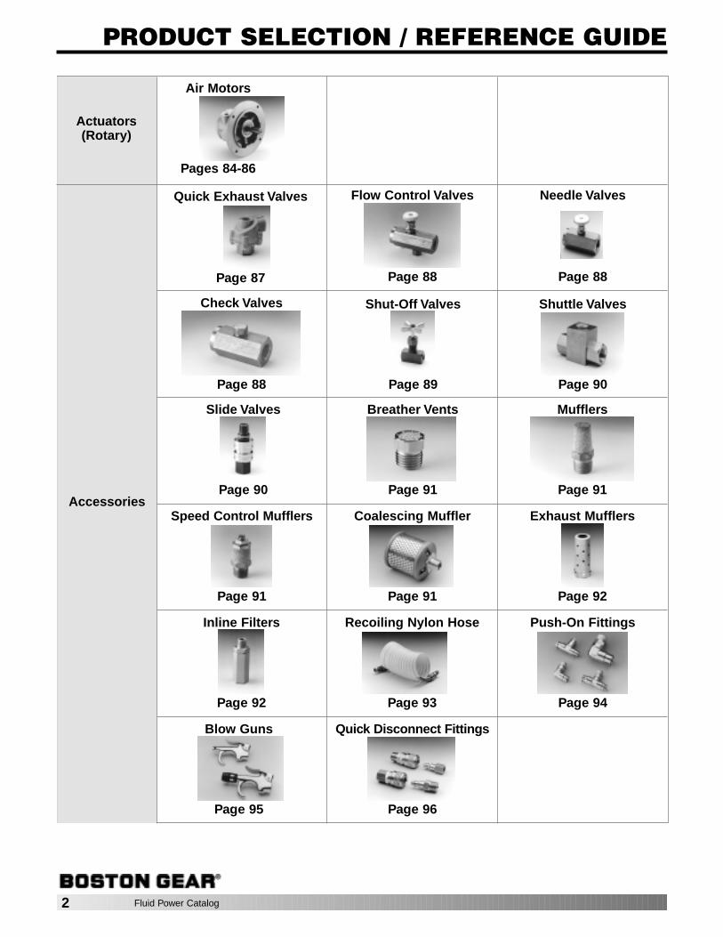
Quick Exhaust Valves
Page 87
Shut-Off Valves
Page 89
Slide Valves
Page 90
Inline Filters
Page 92
Flow Control Valves
Page 88
Mufflers
Page 91
Breather Vents
Page 91Accessories
Needle Valves
Page 88
Speed Control Mufflers
Page 91
Coalescing Muffler
Page 91
Push-On Fittings
Page 94
Blow Guns
Page 95
Check Valves
Page 88
Shuttle Valves
Page 90
Exhaust Mufflers
Page 92
Recoiling Nylon Hose
Page 93
Quick Disconnect Fittings
Page 96
Air Motors
Pages 84-86
Actuators(Rotary)
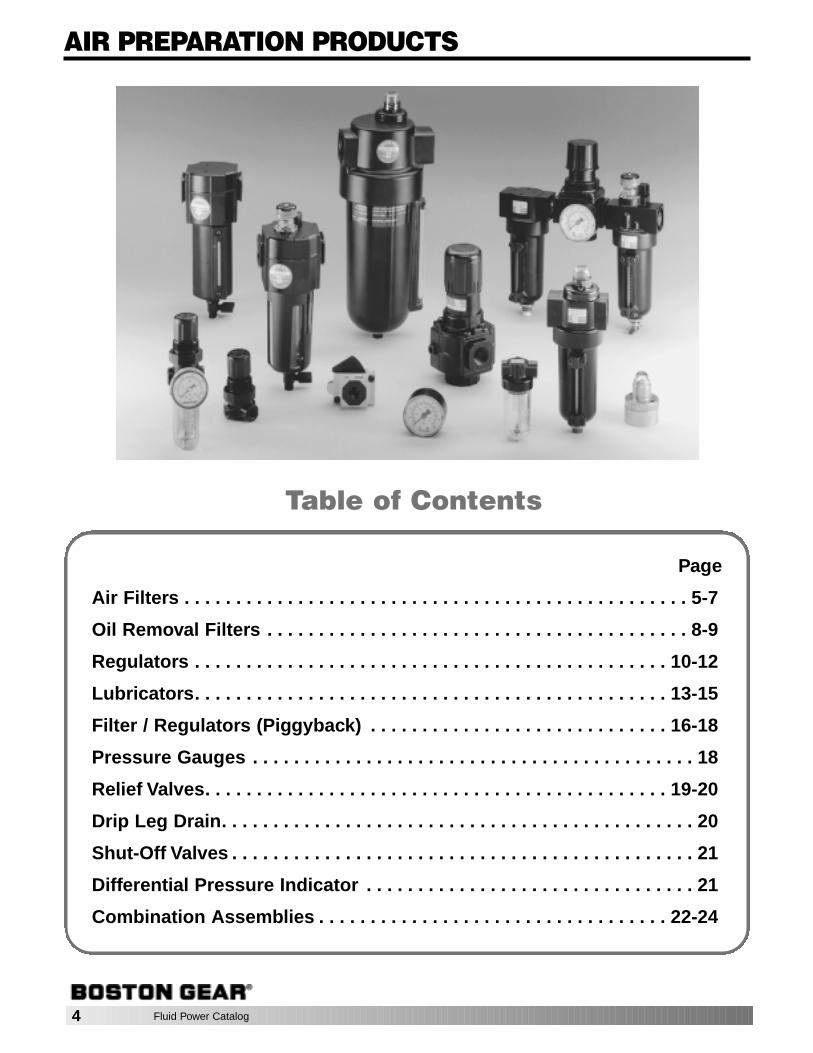
AIR PREPARATION PRODUCTS
Page
Air Filters . . . . . . . . . . . . . . . . . . . . . . . . . . . . . . . . . . . . . . . . . . . . . . . . . 5-7
Oil Removal Filters . . . . . . . . . . . . . . . . . . . . . . . . . . . . . . . . . . . . . . . . . 8-9
Regulators . . . . . . . . . . . . . . . . . . . . . . . . . . . . . . . . . . . . . . . . . . . . . . 10-12
Lubricators. . . . . . . . . . . . . . . . . . . . . . . . . . . . . . . . . . . . . . . . . . . . . . 13-15
Filter / Regulators (Piggyback) . . . . . . . . . . . . . . . . . . . . . . . . . . . . . 16-18
Pressure Gauges . . . . . . . . . . . . . . . . . . . . . . . . . . . . . . . . . . . . . . . . . . . 18
Relief Valves. . . . . . . . . . . . . . . . . . . . . . . . . . . . . . . . . . . . . . . . . . . . . 19-20
Drip Leg Drain. . . . . . . . . . . . . . . . . . . . . . . . . . . . . . . . . . . . . . . . . . . . . . 20
Shut-Off Valves . . . . . . . . . . . . . . . . . . . . . . . . . . . . . . . . . . . . . . . . . . . . . 21
Differential Pressure Indicator . . . . . . . . . . . . . . . . . . . . . . . . . . . . . . . . 21
Combination Assemblies . . . . . . . . . . . . . . . . . . . . . . . . . . . . . . . . . . 22-24
Table of Contents
4 Fluid Power Catalog
3.78AUTOMATIC
DRAIN
3.25MANUALDRAIN
.38
.27DIA.
1.63DIA.
0.911.45DIA.
0.91 0.73
MTG. HOLE (2 PLACES)0.157 DIA.0.5 DEEP
ACCESSORIES / REPAIR PARTS, PAGE 7
Fluid Power Catalog 5
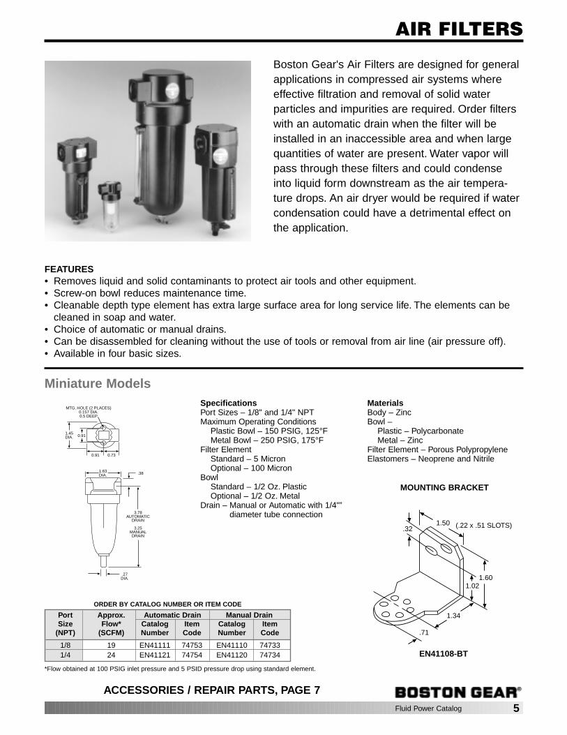
AIR FILTERS
Boston Gear's Air Filters are designed for generalapplications in compressed air systems whereeffective filtration and removal of solid waterparticles and impurities are required. Order filterswith an automatic drain when the filter will beinstalled in an inaccessible area and when largequantities of water are present. Water vapor willpass through these filters and could condenseinto liquid form downstream as the air tempera-ture drops. An air dryer would be required if watercondensation could have a detrimental effect onthe application.
FEATURES• Removes liquid and solid contaminants to protect air tools and other equipment.• Screw-on bowl reduces maintenance time.• Cleanable depth type element has extra large surface area for long service life. The elements can be
cleaned in soap and water.• Choice of automatic or manual drains.• Can be disassembled for cleaning without the use of tools or removal from air line (air pressure off).• Available in four basic sizes.
SpecificationsPort Sizes – 1/8" and 1/4" NPTMaximum Operating Conditions
Plastic Bowl – 150 PSIG, 125°FMetal Bowl – 250 PSIG, 175°F
Filter ElementStandard – 5 MicronOptional – 100 Micron
BowlStandard – 1/2 Oz. PlasticOptional – 1/2 Oz. Metal
Drain – Manual or Automatic with 1/4"”diameter tube connection
MaterialsBody – ZincBowl –
Plastic – PolycarbonateMetal – Zinc
Filter Element – Porous PolypropyleneElastomers – Neoprene and Nitrile
Miniature Models
ORDER BY CATALOG NUMBER OR ITEM CODE
Port Approx. Automatic Drain Manual DrainSize Flow* Catalog Item Catalog Item
(NPT) (SCFM) Number Code Number Code
1/8 19 EN41111 74753 EN41110 747331/4 24 EN41121 74754 EN41120 74734
*Flow obtained at 100 PSIG inlet pressure and 5 PSID pressure drop using standard element.
1.601.02
1.34
.71
.321.50 (.22 x .51 SLOTS)
MOUNTING BRACKET
EN41108-BT

6 Fluid Power Catalog
AIR FILTERS
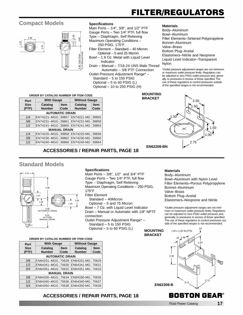
SpecificationsPort Sizes – 1/4", 3/8" and 1/2" PTFMaximum Operating Conditions
– 250 PSIG, 175°FFilter Element
Standard – 40 MicronOptional – 5, 25 Micron
Bowl – 1.9 Oz. Metal with Liquid LevelIndicator Lens
Drain – Manual – 7/16-24 UNS male threadAutomatic – 1/8 PTF connection
MaterialsBody – AluminumBowl – AluminumFilter Element – Sintered PolypropyleneElastomers – Neoprene and NitrileLiquid Level Indicator Lens – Transparent
Nylon
Compact Models
SpecificationsPort Sizes – 3/8", 1/2" and 3/4" PTFMaximum Operating Conditions
– 250 PSIG, 175°FFilter Element
Standard – 40 MicronOptional – 5 and 75 Micron
Bowl – 7 Oz. Metal with Liquid LevelIndicator Lens
Drain – Manual – 7/16-24 UNS male threadAutomatic – 1/8" PTF connection
MaterialsBody – AluminumBowl – Aluminum Filter Element – Sintered PolypropyleneElastomers – Neoprene and NitrileLiquid Level Indicator Lens – Transparent
Nylon
Standard Models
2.68
2.45
1.22
1.00
5.80
Aut
o D
rain
6.15
Automatic Drain1/4 Turn Manual Drain
6.15
Man
ual D
rain
2.89
1.45
1.00
6.35 AUTOMATIC
DRAIN
6.951/4 TURN
MANUAL DRAIN
3.15
ORDER BY CATALOG NUMBER OR ITEM CODE
Port Approx. Automatic Drain Manual DrainSize Flow* Catalog Item Catalog Item
(PTF) (SCFM) Number Code Number Code
1/4 62 EN71221-MG 39914 EN71220-MG 399153/8 75 EN71231-MG 39916 EN71230-MG 399171/2 80 EN71241-MG 39918 EN71240-MG 39919
ORDER BY CATALOG NUMBER OR ITEM CODE
Port Approx. Automatic Drain Manual DrainSize Flow* Catalog Item Catalog Item
(PTF) (SCFM) Number Code Number Code
3/8 120 EN61331-MG 70683 EN61330-MG 706861/2 150 EN61341-MG 70684 EN61340-MG 706873/4 150 EN61351-MG 70685 EN61350-MG 70688
*Flow obtained at 100 PSIG inlet pressure and 5 PSID pressure drop using standard element.
1.10.16
.24
1.89
2.372.64
2.40
(.28 × .71 slots)
1.46.16
.24
1.97
2.72
2.40
3.11
(.20 x 1.00 SLOTS)
MOUNTING BRACKET
EN71208-B
*Flow obtained at 100 PSIG inlet pressure and 5 PSID pressure drop using standard element.
MOUNTING BRACKET
EN62308-B
ACCESSORIES / REPAIR PARTS, PAGE 7
ACCESSORIES / REPAIR PARTS, PAGE 7
ORDER BY CATALOG NUMBER OR ITEM CODE
Miniature Compact Standard JumboDescription Catalog Item Catalog Item Catalog Item Catalog Item
Number Code Number Code Number Code Number Code
Service Kit (Seals) EN71209 39836 EN61309 70669 EN41409 70719Plastic Bowl
Manual Drain EN41109-PBT 74144 EN61209-PB 70324Automatic Drain EN41109-PBAT 74787 EN61209-PBA 70325
Metal BowlManual Drain EN41109-MB 74142 EN71209-MG 39843 EN61309-MG 76811 EN41409-MG 74923Automatic Drain EN41109-MAT 74143 EN71209-MGA 39844 EN61309-MGA 71082 EN41409-MGA —
Filter Element5 Micron EN41109-5 74735 EN71209-5 39850 EN61309-5 70670 EN41409-5 7498325 Micron EN71209-25 39851 EN41409-25 7180340 Micron EN71209-40 39852 EN61309-40 7067150 Micron EN41409-50 7475175 Micron EN61309-75 — EN41409-75 —100 Micron EN41109-100 —
Automatic Drain Kit EN71001 39829 EN41001 74752 EN41001 74752Manual Drain Kit EN61009 71084 EN61009 71084 EN41009 71405Mounting Bracket
All EN41108-BT 76824 EN71208-B 39846 EN62308-B 706773/4 & 1" Ports EN41408-BA 768251-1/4 & 1-1/2 Ports EN41408-BB 76826
Connector † EN61308-C 76812 EN61308-C 76812Connector with EN61308-CB 76813 EN61308-CB 76813
Mounting Feet †Mounting Feet † EN61308-F 39833 EN61308-F 39833
Fluid Power Catalog 7
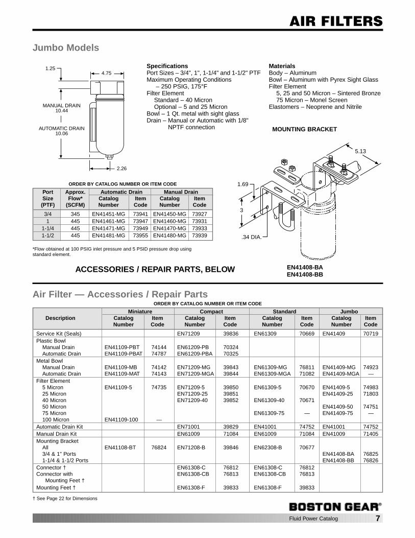
AIR FILTERS
SpecificationsPort Sizes – 3/4", 1", 1-1/4" and 1-1/2" PTFMaximum Operating Conditions
– 250 PSIG, 175°FFilter Element
Standard – 40 MicronOptional – 5 and 25 Micron
Bowl – 1 Qt. metal with sight glassDrain – Manual or Automatic with 1/8"
NPTF connection
MaterialsBody – AluminumBowl – Aluminum with Pyrex Sight GlassFilter Element
5, 25 and 50 Micron – Sintered Bronze75 Micron – Monel Screen
Elastomers – Neoprene and Nitrile
1.254.75
MANUAL DRAIN10.44
AUTOMATIC DRAIN10.06
2.26
Jumbo Models
ORDER BY CATALOG NUMBER OR ITEM CODE
Port Approx. Automatic Drain Manual DrainSize Flow* Catalog Item Catalog Item
(PTF) (SCFM) Number Code Number Code
3/4 345 EN41451-MG 73941 EN41450-MG 739271 445 EN41461-MG 73947 EN41460-MG 73931
1-1/4 445 EN41471-MG 73949 EN41470-MG 739331-1/2 445 EN41481-MG 73955 EN41480-MG 73939
*Flow obtained at 100 PSIG inlet pressure and 5 PSID pressure drop usingstandard element.
1.69
3
.34 DIA.
5.13
ACCESSORIES / REPAIR PARTS, BELOW
MOUNTING BRACKET
EN41408-BAEN41408-BB
Air Filter — Accessories / Repair Parts
† See Page 22 for Dimensions

8 Fluid Power Catalog
Boston Gear's oil removal (coalescing) filters are used in compressed air systemsto provide an extremely clean air supply virtually free of oil aerosols. Unwanted oilis often introduced into compressed air systems by the lubricating oil in the aircompressor. Typical applications include paint spraying, pneumatic control instru-mentation, printing and paper separation and protection of air bearings and fluidicinstrumentation. Oil removal filters are supplied with an automatic drain and a ser-vice life indicator as standard features. The service life indicator provides visualindication of the condition of the filter element, eliminating the guesswork of whento replace the element. The indicator shows green when new and as the pressuredifferential across the element increases it will turn to red. To ensure that the filterelement provides a long service life, it is recommended that a standard air filterwith a 5 micron element is placed prior to the oil removal filter.
FEATURES
• High efficiency coalescing element removes particles down to 0.01 micron.Maximum revisioning oil content of air leaving the filter is 0.01 ppm at 70°F withan inlet concentration of 8 ppm.
• Service life indicator shows red as the pressure differential across the elementincreases. Red will be the predominant color when the differential pressureexceeds 10 PSID indicating the element should be replaced.
• Automatic drain to provide automatic purging of contaminants in bowl.
• Can be diassembled for cleaning without tools or removal from air line (air pres-sure off).
• Screw on bowl reduces maintenance time.
• Sight Glass (liquid level indicator) for visual indication of amount of liquid in bowlat all times.
OIL REMOVAL FILTERS
ORDER BY CATALOG NUMBER OR ITEM CODE
Port Size Oil Removal Filter Recommended** Pre-Filter(PTF) Flow* (SCFM) Fig. Catalog Number Item Code Catalog Number
1/4 21 A EN71621-MG 39920 EN71221-5MG
3/8 21 A EN71631-MG 39921 EN71231-5MG20 B EN61631A-MG 70661 EN61331-5MG
1/2 35 B EN61641-MG 70662 EN61341-5MG60 C EN61641-JMG 70663 EN61341-5MG
3/4 60 C EN61651-JMG 70664 EN61351-5MG90 D EN41651-MG 74769 EN61351-5MG
1 125 D EN41661-MG 73984 EN41461-5MG1 1/2 250 E EN41681-MG 74541 EN41481-5MG
2 300 E EN41691-MG 74542 EN41591-25MG
Materials
Specifications
Port sizes–1/4", 3/8", 1/2", 3/4", 1", 1-1/2",and 2" PTF
Maximum Operating Conditions–250 PSIG, 150°F
Bowl–Metal
Drain–Automatic with 1/8" PTF connection.EN61631A-MG
Unit EN71621-MG EN61641-MG EN41651-MG EN41681-MGEN71631-MG EN61641-JMG EN41661-MG EN41691-MG
EN61651-JMG
Body Aluminum Aluminum Aluminum AluminumBowl 1.9 Oz. Aluminum 7 Oz. Aluminum 1 Qt. Aluminum 1/2 Pt. Zinc
Sight Glass Transparent Transparent(Liquid Level Indicator) Nylon Nylon Pyrex Pyrex
Elements Synthetic Fiber and Polyurethane FoamElastomers Nitrile and NeopreneService Life Acetal and Acetal and Aluminum and Aluminum and
Indicator Nylon Nylon Polycarbonate Polycarbonate
*Approximate flow at 100 PSIG inlet pressure and 5 PSID pressure drop.**Refer to air filter section for specifications.
ACCESSORIES / REPAIR PARTS, PAGE 9

Fluid Power Catalog 9
OIL REMOVAL FILTERS2.68
2.45
1.22
1.00
5.80
Aut
o D
rain
MechanicalServiceIndicator 2.36
3.15
1.00
2.36
6.35
2.89
1.45
3.15
1.00
2.36
8.44
2.89
1.45
2.83
4.75
1.25
10.06
2.76
8.22
3.331.86
14.99
FIGURE A FIGURE B FIGURE C FIGURE D FIGURE E
ORDER BY CATALOG NUMBER OR ITEM CODE
EN61631A-MGEN71621-MG EN61641-MG EN41651-MG EN41681-MGEN71631-MG EN61641-JMG EN41661-MG EN41691-MG
Description EN61651-JMG
Catalog Item Catalog Item Catalog Item Catalog ItemNumber Code Number Code Number Code Number Code
Seal Kit EN71609 39838 EN61639 70674 — — — —Metal Bowl EN71209-MG 39843 EN61309-MG 76811 EN41409-MG 74923 EN41309-MG 74922
(Manual Drain)Metal Bowl EN71209-MGA 39844 EN61309-MGA 71082 — — — —
(Automatic Drain)Filler-Element* EN71629 39853 EN61639-01 70675(1) EN41659 74825 EN41689 70668
EN61639-02 70676(2)Automatic Drain EN71001 39829 EN41001 74752 EN41001 74752 EN41001 74752
Service LifeEN5797-50 70672 EN5797-50 70672 EN5796-50 74976 EN5796-50 74976Indicator
Mounting EN71208-B 39846 EN61308-B 70677 EN41408-BA 76825 (3) — —Bracket EN41408-BB 76826 (4)
Accessories/Repair Parts
Notes:*includes O-ring(1) EN61631A-MG & EN61641-MG(2) EN61641-JMG and EN61651-JMG(3) EN41651-MG(4) EN41661-MG
1.10.16
.24
1.89
2.372.64
2.40
(.28 × .71 slots)
1.46.16
.24
1.97
2.72
2.40
3.11
(.20 x 1.00 SLOTS)
1.69
3
.34 DIA.
5.13
EN71208-B EN61308-B EN41408-BA EN41408-BB
Mounting Brackets
10 Fluid Power Catalog
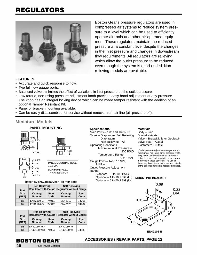
REGULATORS
Boston Gear's pressure regulators are used incompressed air systems to reduce system pres-sure to a level which can be used to efficientlyoperate air tools and other air operated equip-ment. These regulators maintain the reducedpressure at a constant level despite the changesin the inlet pressure and changes in downstreamflow requirements. All regulators are relievingwhich allow the outlet pressure to be reducedeven though the system is dead-ended. Non-relieving models are available.
FEATURES• Accurate and quick response to flow.• Two full flow gauge ports.• Balanced valve minimizes the effect of variations in inlet pressure on the outlet pressure.• Low torque, non-rising pressure adjustment knob provides easy hand adjustment at any pressure.
The knob has an integral locking device which can be made tamper resistant with the addition of anoptional Tamper Resistant Kit.
• Panel or bracket mounting available.• Can be easily disassembled for service without removal from air line (air pressure off).
SpecificationsMain Ports – 1/8" and 1/4" NPTTypes – Diaphragm, Self Relieving
Diaphragm, Non-Relieving (-W)
Operating ConditionsMaximum Inlet Pressure –
300 PSIGTemperature Range –
0 to 150°FGauge Ports – Two 1/8" NPT,
full flowOutlet Pressure AdjustmentRange* –
Standard – 5 to 100 PSIGOptional – 1 to 10 PSIG (LL)Optional – 5 to 50 PSIG (L)
MaterialsBody – ZincBonnet – AcetalValve – Brass/Nitrile or Geolast®Valve Seat – AcetalElastomers – Nitrile
*Outlet pressure adjustment ranges are notminimum or maximum outlet pressure limits.Regulators can be adjusted to zero PSIGoutlet pressure and, generally, to pressuresin excess of those specified. The use ofthese regulators to control pressures outsideof the specified ranges is not recommended.
2.93
PANEL MOUNTING
PANEL MOUNTING HOLE:1.19 DIA.
MAXIMUM PANELTHICKNESS: 0.25
1.33
0.95
0.38
1.50 0.90
1.63
0.73IN
Miniature Models
ORDER BY CATALOG NUMBER OR ITEM CODE
Self Relieving Self Relieving
Port Regulator with Gauge Regulator without Gauge
Size Catalog Item Catalog Item(NPT) Number Code Number Code
1/8 EN42110-G 74911 EN42110 747661/4 EN42120-G 74912 EN42120 74767
Non Relieving Non Relieving
Port Regulator with Gauge Regulator without Gauge
Size Catalog Item Catalog Item(NPT) Number Code Number Code
1/8 EN42110-WG – EN42110-W –1/4 EN42120-WG 74994 EN42120-W 74938
1.00
2.471.50
0.31
0.690.22DIA.
ACCESSORIES / REPAIR PARTS, PAGE 12
MOUNTING BRACKET
EN42108-B

ORDER BY CATALOG NUMBER OR ITEM CODE
Regulator Regulator
Port with Gauge without Gauge
Size Catalog Item Catalog Item(PTF) Number Code Number Code
1/4 EN72220-G 39928 EN72220 399293/8 EN72230-G 39930 EN72230 399311/2 EN72240-G 39932 EN72240 39933
ORDER BY CATALOG NUMBER OR ITEM CODE
Regulator Regulator
Port with Gauge without Gauge
Size Catalog Item Catalog Item(PTF) Number Code Number Code
3/8 EN62330-G 70689 EN62330 706921/2 EN62340-G 70690 EN62340 706933/4 EN62350-G 70691 EN62350 70694
SpecificationsMain Ports – 1/4", 3/8" and 1/2" PTFTypes – Diaphragm, Self RelievingOperating Conditions
Maximum Inlet Pressure – 300 PSIG
Temperature Range – 0 to 175°FGauge Ports – Two 1/4” PTF, full flowOutlet Pressure Adjustment Range* –
Standard – 5 to 150 PSIGOptional – 5 to 60 PSIG (L)Optional – 10 to 250 PSIG (H)
MaterialsBody – AluminumBonnet – AluminumValve – BrassElastomers – NitrileBottom Plug – Acetal
*Outlet pressure adjustment ranges are not minimumor maximum outlet pressure limits. Regulators can beadjusted to zero PSIG outlet pressure and, generally,to pressures in excess of those specified. The use ofthese regulators to control pressures outside of thespecified ranges is not recommended.
Compact Models
1.54
2.68
2.45
1.22
2.20
2.00
1.22
0.45
3.80
SpecificationsMain Ports – 3/8", 1/2" and 3/4" PTFTypes – Diaphragm, Self RelievingOperating Conditions
Maximum Inlet Pressure – 300 PSIGTemperature Range – 0 to 175°F
Gauge Ports – Two 1/4” PTF, full flowOutlet Pressure Adjustment Range* –
Standard – 5 to 150 PSIGOptional – 5 to 60 PSIG (L)
MaterialsBody – AluminumBonnet – AluminumValve – BrassElastomers – NitrileBottom Plug – Acetal
*Outlet pressure adjustment ranges are not mini-mum or maximum outlet pressure limits. Regulatorscan be adjusted to zero PSIG outlet pressure and,generally, to pressures in excess of those specified.The use of these regulators to control pressuresoutside of the specified ranges is not recommended.
Standard Models
1.69
3.15
4.98
1.45
2.89
Fluid Power Catalog 11
REGULATORS
1.50
2.75
1.50
1.50
2.50
1.00
1.46.16
.24
1.97
2.72
2.40
3.11
(.20 x 1.00 SLOTS)
ACCESSORIES / REPAIR PARTS, PAGE 12
MOUNTING BRACKET
EN62208-BN
ACCESSORIES / REPAIR PARTS, PAGE 12
MOUNTING BRACKET
EN62308-B
Note: To mount anFRL Assembly youmay order two (2)pcs EN61308-F(39833) in place ofthis bracket.
Note: To mount anFRL Assembly youmay order two (2)pcs EN61308-F(39833) in place ofthis bracket.
12 Fluid Power Catalog
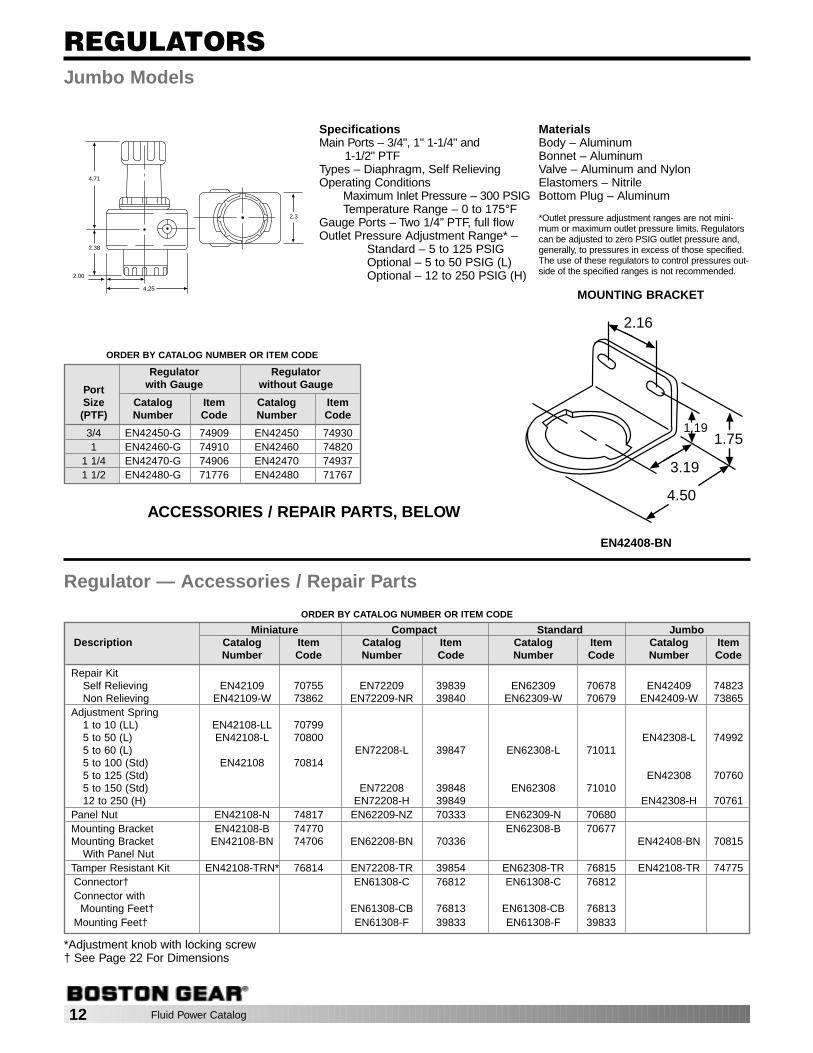
REGULATORS
ORDER BY CATALOG NUMBER OR ITEM CODE
Regulator Regulator
Port with Gauge without Gauge
Size Catalog Item Catalog Item(PTF) Number Code Number Code
3/4 EN42450-G 74909 EN42450 749301 EN42460-G 74910 EN42460 74820
1 1/4 EN42470-G 74906 EN42470 749371 1/2 EN42480-G 71776 EN42480 71767
4.25
2.00
2.38
4.71
2.3
SpecificationsMain Ports – 3/4", 1" 1-1/4" and
1-1/2" PTFTypes – Diaphragm, Self RelievingOperating Conditions
Maximum Inlet Pressure – 300 PSIGTemperature Range – 0 to 175°F
Gauge Ports – Two 1/4” PTF, full flowOutlet Pressure Adjustment Range* –
Standard – 5 to 125 PSIGOptional – 5 to 50 PSIG (L)Optional – 12 to 250 PSIG (H)
MaterialsBody – AluminumBonnet – AluminumValve – Aluminum and NylonElastomers – NitrileBottom Plug – Aluminum
*Outlet pressure adjustment ranges are not mini-mum or maximum outlet pressure limits. Regulatorscan be adjusted to zero PSIG outlet pressure and,generally, to pressures in excess of those specified.The use of these regulators to control pressures out-side of the specified ranges is not recommended.
Jumbo Models
1.75
3.19
2.16
1.19
4.50ACCESSORIES / REPAIR PARTS, BELOW
MOUNTING BRACKET
EN42408-BN
ORDER BY CATALOG NUMBER OR ITEM CODE
Regulator — Accessories / Repair Parts
*Adjustment knob with locking screw† See Page 22 For Dimensions
Miniature Compact Standard JumboDescription Catalog Item Catalog Item Catalog Item Catalog Item
Number Code Number Code Number Code Number Code
Repair KitSelf Relieving EN42109 70755 EN72209 39839 EN62309 70678 EN42409 74823Non Relieving EN42109-W 73862 EN72209-NR 39840 EN62309-W 70679 EN42409-W 73865
Adjustment Spring1 to 10 (LL) EN42108-LL 707995 to 50 (L) EN42108-L 70800 EN42308-L 749925 to 60 (L) EN72208-L 39847 EN62308-L 710115 to 100 (Std) EN42108 708145 to 125 (Std) EN42308 707605 to 150 (Std) EN72208 39848 EN62308 7101012 to 250 (H) EN72208-H 39849 EN42308-H 70761
Panel Nut EN42108-N 74817 EN62209-NZ 70333 EN62309-N 70680Mounting Bracket EN42108-B 74770 EN62308-B 70677Mounting Bracket EN42108-BN 74706 EN62208-BN 70336 EN42408-BN 70815
With Panel NutTamper Resistant Kit EN42108-TRN* 76814 EN72208-TR 39854 EN62308-TR 76815 EN42108-TR 74775Connector† EN61308-C 76812 EN61308-C 76812Connector with
Mounting Feet† EN61308-CB 76813 EN61308-CB 76813Mounting Feet† EN61308-F 39833 EN61308-F 39833

Fluid Power Catalog 13
LUBRICATORS
Boston Gear Lubricators are used in compressed air sys-tems to provide the proper amount of lubrication required fordownstream components. Two styles of lubricators areavailable, the Standard and Micro-Lube. Each has its owncharacteristics as described below.
FEATURES• Flow sensor design provides a nearly constant oil/air
ratio over a wide range of air flows.• All around (360°) visibility of the sight-feed dome sim-
plifies installation and adjustment.• Simple knob type, oil-feed control with integral sight-
feed dome permits fine adjustment of oil-feed rate toprovide the proper degree of lubrication at the point ofneed.
• Final oil-feed adjustment is easily locked with integralpush-pull locking ring on the control knob. OptionalTamper Resistant Kit can be installed to resist unautho-rized adjustment.
Boston Gear offers two styles of lubricators for use in industrial compressed air systems to lubricate air driver devices.Standard Lubricators are used in industrial compressed air systems to lubricate a single air tool, cylinder, valve orair motor. They inject a finely divided "fog" of oil into the air stream. One standard lubricator should be provided foreach device requiring lubrication. The standard lubricators can be filled under pressure.Micro-Lube Lubricators inject a finely divided "Micro-Fog" of oil into the air stream, which allow usage in systemscontaining complex piping and multiple points of lubrication. Typical applications are air tools, cylinders, valves and airmotors.
SpecificationsPort Sizes – 1/8" and 1/4" NPTMaximum Operating Conditions
Plastic Bowl – 150 PSIG, 125°FMetal Bowl – 250 PSIG, 175°F
Bowl Capacity – 1 oz.Recommended Lubricants: Use a misting typeoil rated 50 to 200 SSU (ISO grade 7 to 46) at100°F. The oils must be compatible with mate-rials of construction.
MaterialsBody – ZincBowl –
Plastic – PolycarbonateMetal – Zinc
Sight Feed Dome – Transparent NylonElastomers – Neoprene and Nitrile
Miniature Models
1.45
1.63
FULL
EMPTY
1.98
3.25
ORDER BY CATALOG NUMBER OR ITEM CODE
Port Recommended Micro-Lube LubricatorsSize Flow Range* Catalog Item
(NPT) (SCFM) Number Code
1/8 0.5 to 10 EN43111–F 747901/4 0.5 to 10 EN43121–F 74791
*At 100 PSIG inlet pressure and 5 PSID
1.00
2.471.50
0.31
0.690.22DIA.
ACCESSORIES / REPAIR PARTS, PAGE 15
MOUNTING BRACKET
EN42108-BN

14 Fluid Power Catalog
LUBRICATORSCompact Models
Standard Models
2.68
2.45
1.22
1.00
1.87
6.15
2.89
1.45
6.95
1.00
1.12
3.15
ORDER BY CATALOG NUMBER OR ITEM CODE
Port Recommended Standard Lubricators Micro-Lube LubricatorsSize Flow Range* Catalog Item Catalog Item(PTF) (SCFM) Number Code Number Code
1/4 1.5 to 60 EN73220-MG 39923 EN73220-FMG 399223/8 1.5 to 60 EN73230-MG 39925 EN73230-FMG 399241/2 1.5 to 60 EN73240-MG 39927 EN73240-FMG 39926
1.10.16
.24
1.89
2.372.64
2.40
(.28 × .71 slots)
ORDER BY CATALOG NUMBER OR ITEM CODE
Port Recommended Standard Lubricators Micro-Lube LubricatorsSize Flow Range* Catalog Item Catalog Item(PTF) (SCFM) Number Code Number Code
3/8 2.5 to 40 EN63330-MG 70041 EN63330-FMG 700421/2 3.5 to 100 EN63340-MG 70043 EN63340-FMG 700443/4 3.5 to 100 EN63350-MG 70045 EN63350-FMG 70046
SpecificationsPort Sizes – 3/8", 1/2" and 3/4" PTFMaximum Operating Conditions
– 250 PSIG, 175°FBowl Capacity – 7 Oz.Recommended Lubricants: Use a mistingtype oil rated 50 to 200 SSU (ISO grade 7 to46) at 100°F. The oils must be compatiblewith materials of construction.
MaterialsBody – AluminumBowl – AluminumLiquid Level Indicator – Transparent NylonSight Feed Dome – Transparent NylonElastomers – Neoprene and Nitrile
1.46.16
.24
1.97
2.72
2.40
3.11
(.20 x 1.00 SLOTS)
SpecificationsPort Sizes – 1/4", 3/8", and 1/2" PTFMaximum Operating Conditions
– 250 PSIG, 175°FBowl Capacity – 3.5 Oz.Recommended Lubricants: Use a misting typeoil rated 50 to 200 SSU (ISO grade 7 to 46) at100°F. The oils must be compatible with mate-rials of construction.
MaterialsBody – AluminumBowl – AluminumSight Feed Dome – Transparent NylonElastomers – Neoprene and NitrileCapsule (Micro-Lube) – Red AcetalLiquid Level Indicator Lens – Transparent
Nylon
*At 100 PSIG inlet pressure and 5 PSID
*At 100 PSIG inlet pressure and 5 PSID
ACCESSORIES / REPAIR PARTS, PAGE 15
MOUNTING BRACKET
EN71208-B
ACCESSORIES / REPAIR PARTS, PAGE 15
MOUNTING BRACKET
EN62308-B

ORDER BY CATALOG NUMBER OR ITEM CODE
Port Recommended Standard Lubricators Micro-Lube LubricatorsSize Flow Range* Catalog Item Catalog Item(PTF) (SCFM) Number Code Number Code
3/4 8 to 160 EN43450-MG 73957 EN43450-FMG 739731 8 to 275 EN43460-MG 73963 EN43460-FMG 73979
1-1/4 8 to 275 EN43470-MG 73965 EN43470-FMG 739811-1/2 8 to 275 EN43480-MG 73971 EN43480-FMG 73983
Fluid Power Catalog 15
LUBRICATORS
SpecificationsPort Sizes – 3/4, 1", 1-1/4" and 1-1/2" PTFMaximum Operating
Conditions – 250 PSIG, 175°FBowl Capacity – 1 Qt.Recommended Lubricants: Use a mistingtype oil rated 50 to 200 SSU (ISO grade 7 to46) at 100°F. The oils must be compatiblewith materials of construction.
MaterialsBody – AluminumBowl – AluminumSight Glass – PyrexSight Feed Dome – Transparent NylonElastomers – Neoprene and Acetal
Jumbo Models
2.76
10.24
4.502.22
1.69
3
.34 DIA.
5.13
*At 100 PSIG inlet pressure and 5 PSID
ACCESSORIES / REPAIR PARTS, BELOW
MOUNTING BRACKET
EN41408-BAEN41408-BB
ORDER BY CATALOG NUMBER OR ITEM CODE
Miniature Compact Standard JumboDescription Catalog Item Catalog Item Catalog Item Catalog Item
Number Code Number Code Number Code Number Code
Service Kit (Seals) EN43109 70991 EN73209 39841 EN63309 70682 EN43409 70985Plastic Bowl EN43109-PB 71074 EN63209-PB 70327Metal Bowl EN43109-M — EN73209-MG 39845 EN63309-MG 70823 EN43409-MG 71083Signt Dome Assembly
Micro-Lubricators EN43109-D 70992 EN73109-D 39831 EN43109-D 70992 EN43109-D 70992Standard-Lubricators EN73209-D 39832 EN43209-D 71012 EN43209-D 71012
Fill Plug EN43109-FP 71785 EN63209-FP 70717 EN63209-FP 70717 EN43309-FP 71787Manual Drain Kit EN61009 71084 EN41009 71405Mounting Bracket
All EN42108-BN 74706 EN71208-B 39846 EN62308-B 706773/4 & 1" Ports EN41408-BA 768251-1/4 & 1-1/2 Ports EN41408-BB 76826
Tamper Resistant Kit EN42108-TR 74775 EN73208-TR 39830 EN42108-TR 74775 EN42108-TR 74775Connector† EN61308-C 76812 EN61308-C 76812Connector with
Mounting Feet† EN61308-CB 76813 EN61308-CB 76813Mounting Feet† EN61308-F 39833 EN61308-F 39833
Lubricator — Accessories / Repair Parts
† See Page 22 for Dimensions
16 Fluid Power Catalog
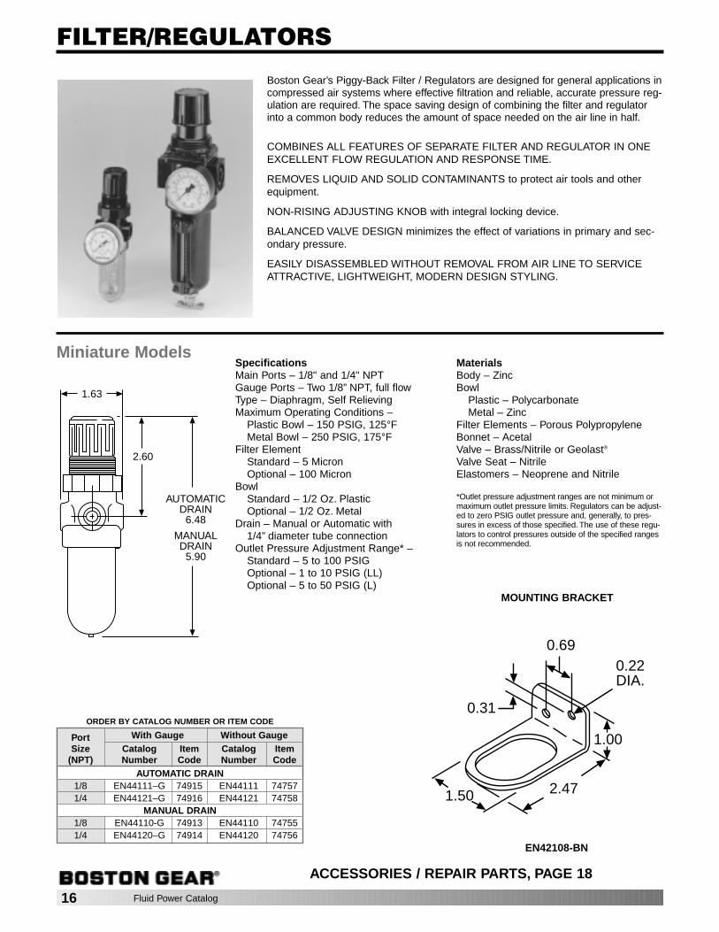
FILTER/REGULATORS
Boston Gear’s Piggy-Back Filter / Regulators are designed for general applications incompressed air systems where effective filtration and reliable, accurate pressure reg-ulation are required. The space saving design of combining the filter and regulatorinto a common body reduces the amount of space needed on the air line in half.
COMBINES ALL FEATURES OF SEPARATE FILTER AND REGULATOR IN ONEEXCELLENT FLOW REGULATION AND RESPONSE TIME.
REMOVES LIQUID AND SOLID CONTAMINANTS to protect air tools and otherequipment.
NON-RISING ADJUSTING KNOB with integral locking device.
BALANCED VALVE DESIGN minimizes the effect of variations in primary and sec-ondary pressure.
EASILY DISASSEMBLED WITHOUT REMOVAL FROM AIR LINE TO SERVICEATTRACTIVE, LIGHTWEIGHT, MODERN DESIGN STYLING.
AUTOMATICDRAIN
6.48
MANUALDRAIN
5.90
2.60
1.63
ORDER BY CATALOG NUMBER OR ITEM CODE
Port With Gauge Without GaugeSize Catalog Item Catalog Item
(NPT) Number Code Number CodeAUTOMATIC DRAIN
1/8 EN44111–G 74915 EN44111 747571/4 EN44121–G 74916 EN44121 74758
MANUAL DRAIN1/8 EN44110-G 74913 EN44110 747551/4 EN44120–G 74914 EN44120 74756
SpecificationsMain Ports – 1/8" and 1/4" NPTGauge Ports – Two 1/8” NPT, full flowType – Diaphragm, Self RelievingMaximum Operating Conditions –
Plastic Bowl – 150 PSIG, 125°FMetal Bowl – 250 PSIG, 175°F
Filter ElementStandard – 5 MicronOptional – 100 Micron
BowlStandard – 1/2 Oz. PlasticOptional – 1/2 Oz. Metal
Drain – Manual or Automatic with 1/4” diameter tube connection
Outlet Pressure Adjustment Range* – Standard – 5 to 100 PSIGOptional – 1 to 10 PSIG (LL)Optional – 5 to 50 PSIG (L)
MaterialsBody – ZincBowl
Plastic – PolycarbonateMetal – Zinc
Filter Elements – Porous PolypropyleneBonnet – AcetalValve – Brass/Nitrile or Geolast®
Valve Seat – NitrileElastomers – Neoprene and Nitrile
*Outlet pressure adjustment ranges are not minimum ormaximum outlet pressure limits. Regulators can be adjust-ed to zero PSIG outlet pressure and, generally, to pres-sures in excess of those specified. The use of these regu-lators to control pressures outside of the specified rangesis not recommended.
1.00
2.471.50
0.31
0.690.22DIA.
ACCESSORIES / REPAIR PARTS, PAGE 18
MOUNTING BRACKET
EN42108-BN
Miniature Models
Fluid Power Catalog 17
ORDER BY CATALOG NUMBER OR ITEM CODE
Port With Gauge Without GaugeSize Catalog Item Catalog Item
(PTF) Number Code Number CodeAUTOMATIC DRAIN
1/4 EN74221–MGG 39857 EN74221-MG 398553/8 EN74231–MGG 39861 EN74231-MG 398591/2 EN74241–MGG 39865 EN74241-MG 39863
MANUAL DRAIN1/4 EN74220–MGG 39858 EN74220-MG 398563/8 EN74230–MGG 39862 EN74230-MG 398601/2 EN74240–MGG 39866 EN74240-MG 39864
FILTER/REGULATORS
0.45
2.68
2.45
1.22
2.20
2.00
1.22
3.80
Aut
o D
rain
5.80
6.15
Man
ual D
rain
ORDER BY CATALOG NUMBER OR ITEM CODE
Port With Gauge Without GaugeSize Catalog Item Catalog Item
(PTF) Number Code Number CodeAUTOMATIC DRAIN
3/8 EN64331–MGG 70628 EN64331-MG 706291/2 EN64341–MGG 70630 EN64341-MG 706313/4 EN64351–MGG 70632 EN64351-MG 70633
MANUAL DRAIN3/8 EN64330–MGG 70634 EN64330-MG 706351/2 EN64340–MGG 70636 EN64340-MG 706373/4 EN64350–MGG 70638 EN64350-MG 70639
3.15
4.98
1.24
1.69
6.95AUTOMATIC DRAIN
6.351/4 TURN
MANUAL DRAIN
1.45
2.89
Compact Models SpecificationsMain Ports – 1/4", 3/8", and 1/2" PTFGauge Ports – Two 1/4” PTF, full flowType – Diaphragm, Self RelievingMaximum Operating Conditions –
250 PSIG, 175°FFilter Element – Standard – 40 Micron;
Optional – 5 and 25 MicronBowl – 1.9 Oz. Metal with Liquid Level
IndicatorDrain – Manual – 7/16-24 UNS Male Thread
Automatic – 3/8 PTF ConnectionOutlet Pressure Adjustment Range* –
Standard – 5 to 150 PSIGOptional – 5 to 60 PSIG (L)Optional – 10 to 250 PSIG (H)
Standard ModelsSpecificationsMain Ports – 3/8", 1/2" and 3/4" PTFGauge Ports – Two 1/4” PTF, full flowType – Diaphragm, Self RelievingMaximum Operating Conditions – 250 PSIG,175°FFilter Element
Standard – 40MicronOptional – 5 and 75 Micron
Bowl – 7 Oz. with Liquid Level IndicatorDrain – Manual or Automatic with 1/8" NPTFconnectionOutlet Pressure Adjustment Range* –
Standard – 5 to 150 PSIGOptional – 5 to 60 PSIG (L)
MaterialsBody–AluminumBowl–AluminumFilter Elements–Sintered PolypropyleneBonnet–AluminumValve–BrassBottom Plug–AcetalElastomers–Nitrile and NeopreneLiquid Level Indicator–TransparentNylon
*Outlet pressure adjustment ranges are not minimumor maximum outlet pressure limits. Regulators canbe adjusted to zero PSIG outlet pressure and, gener-ally, to pressures in excess of those specified. Theuse of these regulators to control pressures outsideof the specified ranges is not recommended.
1.50
2.75
1.50
1.50
2.50
1.00
MaterialsBody–AluminumBowl–Aluminum with Nylon LevelFilter Elements–Porous PolypropyleneBonnet–AluminumValve–BrassBottom Plug–AcetalElastomers–Neoprene and Nitrile
*Outlet pressure adjustment ranges are not mini-mum or maximum outlet pressure limits. Regulatorscan be adjusted to zero PSIG outlet pressure and,generally, to pressures in excess of those specified.The use of these regulators to control pressures out-side of the specified ranges is not recommended.
1.46.16
.24
1.97
2.72
2.40
3.11
(.20 x 1.00 SLOTS)
ACCESSORIES / REPAIR PARTS, PAGE 18
MOUNTINGBRACKET
EN62208-BN
ACCESSORIES / REPAIR PARTS, PAGE 18
MOUNTINGBRACKET
EN62308-B
18 Fluid Power Catalog
FILTER / REGULATORS
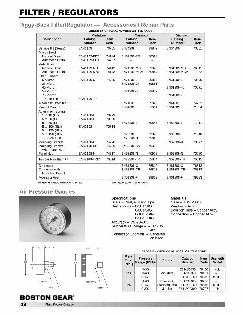
ORDER BY CATALOG NUMBER OR ITEM CODE
Pipe Pressure Catalog Item Use withSize
Range (PSIG)Series
Number Code Model(NPT)
0-30 E61-1C030 78400 –LL1/8 0-60 Miniature E61-1C060 78401 –L
0-160 E61-1C0160 70515 (STD)0-60 Compact, E61-2C060 70796 –L
1/4 0-160 Standard, and E61-2C0160 70516 (STD)0-300 Jumbo E61-2C0300 70797 –H
SpecificationsScale – Dual, PSI and KpaDial Ranges – 0-30 PSIG
0-60 PSIG0-160 PSIG0-300 PSIG
Accuracy – 3%-2%-3%Temperature Range – – 10°F to
140°FConnection Location – Centered
on back
MaterialsCase – ABS PlasticWindow – AcrylicBourdon Tube – Copper AlloyConnection – Copper Alloy
Air Pressure Gauges
9/16 SQUARE
1/4 NPT
2.28
1.22 .93
7/16 SQUARE
1/8 NPT
1.65
.99 .72
ORDER BY CATALOG NUMBER OR ITEM CODE
Miniature Compact StandardDescription Catalog Item Catalog Item Catalog Item
Number Code Number Code Number Code
Service Kit (Seals) EN42109 70755 EN74209 39842 EN64309 70681Plastic Bowl
Manual Drain EN41109-PBT 74144 EN61209-PB 70324Automatic Drain EN41109-PBAT 74787 – –
Metal BowlManual Drain EN41109-MB 74142 EN71209-MG 39843 EN61309-MG 76811Automatic Drain EN41109-MAT 74143 EN71209-MGA 39844 EN61309-MGA 71082
Filter Element5 Micron EN41109-5 74735 EN71209-5 39850 EN61309-5 7067025 Micron EN71209-25 3985140 Micron EN61309-40 7067150 Micron EN71209-40 3985275 Micron EN61309-75 ———100 Micron EN41109-100 ———
Automatic Drain Kit EN71001 39829 EN41001 74752Manual Drain Kit EN61009 71084 EN61009 71084Adjustment Spring
1 to 10 (LL) EN42108-LL 707995 to 50 (L) EN42108-L 708005 to 60 (L) EN72208-L 39847 EN62308-L 710115 to 100 (Std) EN42108 708145 to 125 (Std)5 to 150 (Std) EN72208 39848 EN62308 7101012 to 250 (H) EN72208-H 39849
Mounting Bracket EN42108-B 74770 EN62308-B 70677Mounting Bracket EN42108-BN 74706 EN62208-BN 70336
With Panel NutPanel Nut EN42108-N 74817 EN62208-N 70978 EN62309-N 70680
Tamper Resistant Kit EN42108-TRN* 76814 EN72208-TR 39854 EN62309-TR 76815
Connector † EN61308-C 76812 EN61308-C 76812Connector with EN61308-CB 76813 EN61308-CB 76813
Mounting Feet †Mounting Feet † EN61308-F 39833 EN61308-F 39833
Piggy-Back Filter/Regulator — Accessories / Repair Parts
*Adjustment knob with locking screw † See Page 22 For Dimensions

Fluid Power Catalog 19
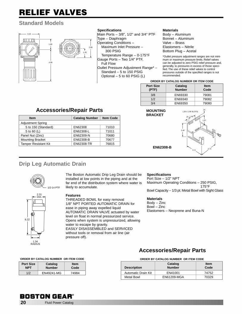
RELIEF VALVES
A relief valve is used in a compressed air system to retard excessiveair pressure buildup and thereby help prevent damage to systemcomponents.
FEATURES
ATTRACTIVE, LIGHTWEIGHT STYLINGSTANDARD NON-RISING ADJUSTING KNOB with integral lockingdevice which can be made tamper resistantINLINE MOUNTINGEASILY DISASSEMBLED FOR SERVICING without removal fromair line. (Air Pressure Off)
Miniature Models
2.93
PANEL MOUNTING
PANEL MOUNTING HOLE:1.19 DIA.
MAXIMUM PANELTHICKNESS: 0.25
1.33
0.95
0.38
1.50 0.90
1.63
0.73OUT
ORDER BY CATALOG NUMBER OR ITEM CODE
Port Size Catalog Item(NPT) Number Code
1/8 EN49110 749861/4 EN49120 74987
SpecificationsMain Ports – 1/8" and 1/4" NPTType – DiaphragmOperating Conditions –
Maximum Inlet Pressure – 300PSIG
Temperature Range – 0-150°FGauge Ports – Two 1/8” NPT, FullFlowOutlet Pressure AdjustmentRange* –
Standard – 5 to 100 PSIGOptional – 1 to 10 PSIG (LL)Optional – 2 to 50 PSIG (L)
MaterialsBody – ZincBonnet – AcetalValve – Brass/Nitrile or Geolast®
Valve Seat – AcetalElastomers – Nitrile
*Outlet pressure adjustment ranges are notminimum or maximum pressure limits. Reliefvalves can be adjusted to zero PSIG reliefpressure and, generally, to pressures inexcess of those specified. The use of theserelief valves to control pressures outside ofthe specified ranges is not recommended.
Accessories/Repair Parts
1.00
2.471.50
0.31
0.690.22DIA.
*Adjustment knob with locking screw
MOUNTINGBRACKET
EN42108-BN
Item Catalog Number Item Code
Adjustment Spring5 to 100 (Standard) EN42108 708141 to 10 (LL) EN42108-LL 707995 to 50 (L) EN42108-L 70800
Panel Nut (Plastic) EN42108-N 74817Mounting Bracket EN42108-B 74770Mounting Bracket with Panel Nut EN42108-BN 74706Tamper Resistant Kit* EN42108-TRN 76814
20 Fluid Power Catalog
RELIEF VALVESStandard Models
1.69
3.15
4.98
1.45
2.89
ORDER BY CATALOG NUMBER OR ITEM CODE
Port Size Catalog Item(PTF) Number Code
3/8 EN69330 790811/2 EN69340 790823/4 EN69350 79080
SpecificationsMain Ports – 3/8", 1/2" and 3/4" PTFType – DiaphragmOperating Conditions –
Maximum Inlet Pressure – 300 PSIG
Temperature Range – 0-175°FGauge Ports – Two 1/4" PTF,
Full FlowOutlet Pressure Adjustment Range* –
Standard – 5 to 150 PSIGOptional – 5 to 60 PSIG (L)
MaterialsBody – AluminumBonnet – AluminumValve – BrassElastomers – NitrileBottom Plug – Acetal*Outlet pressure adjustment ranges are not mini-mum or maximum pressure limits. Relief valvescan be adjusted to zero PSIG relief pressure and,generally, to pressures in excess of those speci-fied. The use of these relief valves to controlpressures outside of the specified ranges is notrecommended.
Accessories/Repair Parts1.46.16
.24
1.97
2.72
2.40
3.11
(.20 x 1.00 SLOTS)
1/2-14 PTF
2.31DIA.
6.22
1.34RADIUS
ORDER BY CATALOG NUMBER OR ITEM CODE
Catalog ItemDescription Number Code
Automatic Drain Kit EN41001 74752Metal Bowl EN61209-MGA 70329
The Boston Automatic Drip Leg Drain should beinstalled at low points in the piping and at thefar end of the distribution system where water islikely to accumulate.
FeaturesTHREADED BOWL for easy removal1/8" NPT PORTED AUTOMATIC DRAIN forease in piping away expelled liquidAUTOMATIC DRAIN VALVE actuated by waterlevel on float in normal pressurized service.Opens when system is unpressurized, allowingwater to escape by gravity.EASILY DISASSEMBLED and SERVICED without tools or removal from air line (air pressure off).
SpecificationsPort Size – 1/2" NPTMaximum Operating Conditions – 250 PSIG,
175°FBowl Capacity – 1/3 pt. Metal Bowl with Sight Glass
MaterialsBody – ZincBowl – ZincElastomers – Neoprene and Buna-N
Drip Leg Automatic Drain
ORDER BY CATALOG NUMBER OR ITEM CODE
Port Size Catalog ItemNPT Number Code
1/2 EN49241-MG 74984
Accessories/Repair Parts
MOUNTINGBRACKET
EN62308-B
Item Catalog Number Item Code
Adjustment Spring5 to 150 (Standard) EN62308 710105 to 60 (L) EN62308-L 71011
Panel Nut (Zinc) EN62309-N 70680Mounting Bracket EN62308-B 70677Tamper Resistant Kit EN62308-TR 76815

Fluid Power Catalog 21
Shut-Off Valves, typically attach to the inlet end of a combination unit, are manually oper-ated, slide type valves that open and close with a short one-inch movement of the slide.The valve slide can be locked in the closed position with a customer supplied padlock.The standard valve is a 3-way valve that exhausts downstream air in the closed position.
SHUT-OFF VALVES
SPECIFICATIONSPorts – 1/4", 3/8" and 1/2" PTFOperating Conditions –
Maximum Inlet Pressure – 250 PSIGTemperature Range – 0 to 175°F
MATERIALSBody – ZincSlide – AcetalElastomers – Nitrile
1.31 1.00 1.80
2.90
0.28 DIAMETER HOLE FOR LOCK
OPEN
ORDER BY CATALOG NUMBER OR ITEM CODE
Port Size Catalog Item(PTF) Number Code
1/4 EN60223 703113/8 EN60233 703121/2 EN60243 70547
The differential pressure indicator, usingthe familiar “stop” and “go” colors, red andgreen, is used to monitor the pressuredrop across air line filters and other com-ponents. It is a standard feature on allBoston Oil Removal Filters. The Differ-ential Pressure Indicator can also beused inline to measure pressure dropacross any device in an air circuit.
Color CodeGREEN: Pressure drop less than 6 psigGREEN/RED: Pressure drop between 6and 15 psigRED: Pressure drop greater than 15 psig
SpecificationsPorts – 1/8" PTFMaximum Rated Operating Conditions –250 psig, 175°F
MaterialsBody – AluminumLens – PolycarbonateInternal Parts – Stainless Steel, ABS andAcetalElastomers – Buna-N
Differential Pressure Indicator
.88
1.59DIA.
2.28
ORDER BY CATALOG NUMBEROR ITEM CODE
Catalog ItemDescription Number Code
Differential Pressure Indicator EN41218 74816Replacement Unit forOil Removal Filters EN5796-50 74976Service Kit ENP0550A-02 74975
22 Fluid Power Catalog
COMBINATION ASSEMBLIES
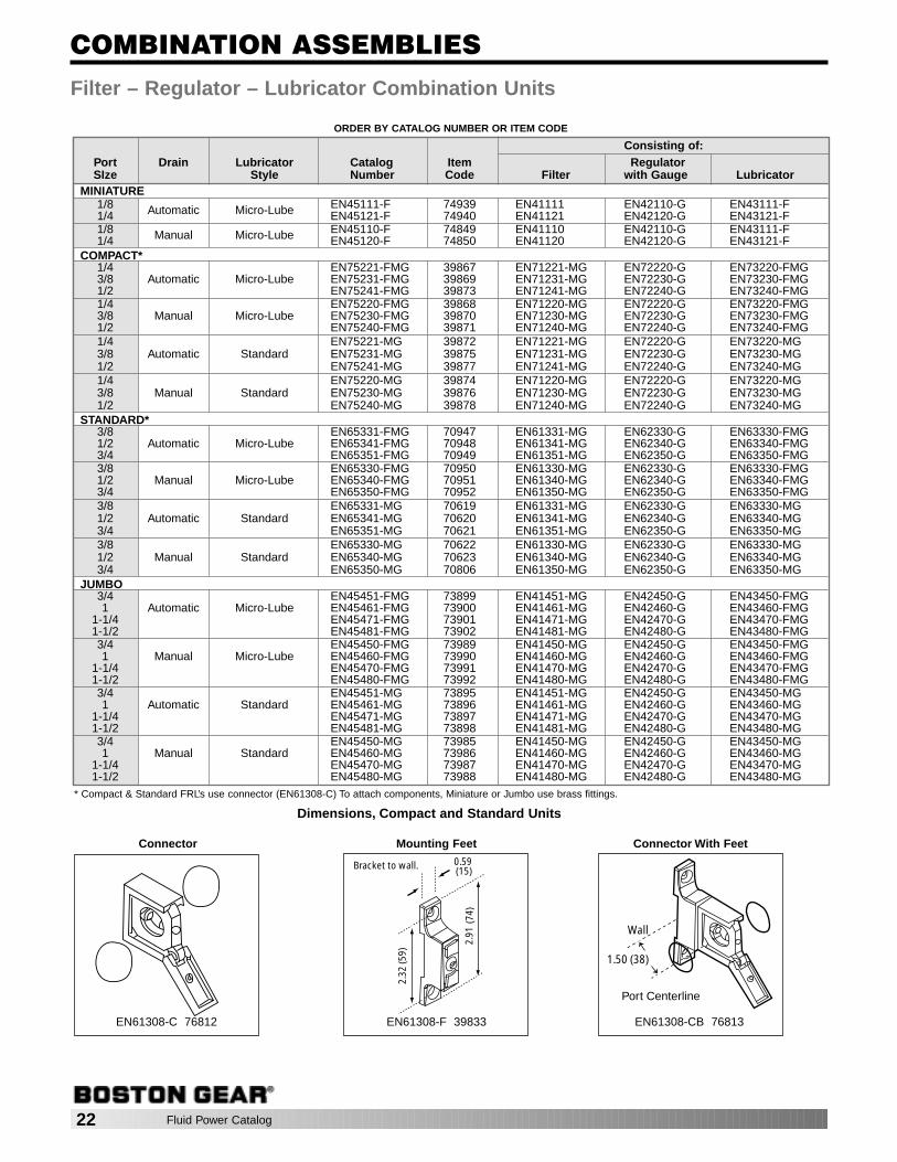
ORDER BY CATALOG NUMBER OR ITEM CODE
Filter – Regulator – Lubricator Combination Units
Consisting of:Port Drain Lubricator Catalog Item RegulatorSIze Style Number Code Filter with Gauge Lubricator
MINIATURE1/8 Automatic Micro-Lube EN45111-F 74939 EN41111 EN42110-G EN43111-F1/4 EN45121-F 74940 EN41121 EN42120-G EN43121-F1/8 Manual Micro-Lube EN45110-F 74849 EN41110 EN42110-G EN43111-F1/4 EN45120-F 74850 EN41120 EN42120-G EN43121-F
COMPACT*1/4 EN75221-FMG 39867 EN71221-MG EN72220-G EN73220-FMG3/8 Automatic Micro-Lube EN75231-FMG 39869 EN71231-MG EN72230-G EN73230-FMG1/2 EN75241-FMG 39873 EN71241-MG EN72240-G EN73240-FMG1/4 EN75220-FMG 39868 EN71220-MG EN72220-G EN73220-FMG3/8 Manual Micro-Lube EN75230-FMG 39870 EN71230-MG EN72230-G EN73230-FMG1/2 EN75240-FMG 39871 EN71240-MG EN72240-G EN73240-FMG1/4 EN75221-MG 39872 EN71221-MG EN72220-G EN73220-MG3/8 Automatic Standard EN75231-MG 39875 EN71231-MG EN72230-G EN73230-MG1/2 EN75241-MG 39877 EN71241-MG EN72240-G EN73240-MG1/4 EN75220-MG 39874 EN71220-MG EN72220-G EN73220-MG3/8 Manual Standard EN75230-MG 39876 EN71230-MG EN72230-G EN73230-MG1/2 EN75240-MG 39878 EN71240-MG EN72240-G EN73240-MG
STANDARD*3/8 EN65331-FMG 70947 EN61331-MG EN62330-G EN63330-FMG1/2 Automatic Micro-Lube EN65341-FMG 70948 EN61341-MG EN62340-G EN63340-FMG3/4 EN65351-FMG 70949 EN61351-MG EN62350-G EN63350-FMG3/8 EN65330-FMG 70950 EN61330-MG EN62330-G EN63330-FMG1/2 Manual Micro-Lube EN65340-FMG 70951 EN61340-MG EN62340-G EN63340-FMG3/4 EN65350-FMG 70952 EN61350-MG EN62350-G EN63350-FMG3/8 EN65331-MG 70619 EN61331-MG EN62330-G EN63330-MG1/2 Automatic Standard EN65341-MG 70620 EN61341-MG EN62340-G EN63340-MG3/4 EN65351-MG 70621 EN61351-MG EN62350-G EN63350-MG3/8 EN65330-MG 70622 EN61330-MG EN62330-G EN63330-MG1/2 Manual Standard EN65340-MG 70623 EN61340-MG EN62340-G EN63340-MG3/4 EN65350-MG 70806 EN61350-MG EN62350-G EN63350-MG
JUMBO3/4 EN45451-FMG 73899 EN41451-MG EN42450-G EN43450-FMG1 Automatic Micro-Lube EN45461-FMG 73900 EN41461-MG EN42460-G EN43460-FMG
1-1/4 EN45471-FMG 73901 EN41471-MG EN42470-G EN43470-FMG1-1/2 EN45481-FMG 73902 EN41481-MG EN42480-G EN43480-FMG3/4 EN45450-FMG 73989 EN41450-MG EN42450-G EN43450-FMG1 Manual Micro-Lube EN45460-FMG 73990 EN41460-MG EN42460-G EN43460-FMG
1-1/4 EN45470-FMG 73991 EN41470-MG EN42470-G EN43470-FMG1-1/2 EN45480-FMG 73992 EN41480-MG EN42480-G EN43480-FMG3/4 EN45451-MG 73895 EN41451-MG EN42450-G EN43450-MG1 Automatic Standard EN45461-MG 73896 EN41461-MG EN42460-G EN43460-MG
1-1/4 EN45471-MG 73897 EN41471-MG EN42470-G EN43470-MG1-1/2 EN45481-MG 73898 EN41481-MG EN42480-G EN43480-MG3/4 EN45450-MG 73985 EN41450-MG EN42450-G EN43450-MG1 Manual Standard EN45460-MG 73986 EN41460-MG EN42460-G EN43460-MG
1-1/4 EN45470-MG 73987 EN41470-MG EN42470-G EN43470-MG1-1/2 EN45480-MG 73988 EN41480-MG EN42480-G EN43480-MG
2.91
(74)
2.32
(59)
0.59(15)
Bracket to wall.
Wall
1.50 (38)
Port Centerline
Connector Connector With FeetMounting Feet
EN61308-C 76812 EN61308-F 39833 EN61308-CB 76813
* Compact & Standard FRL’s use connector (EN61308-C) To attach components, Miniature or Jumbo use brass fittings.
Dimensions, Compact and Standard Units
Fluid Power Catalog 23
COMBINATION ASSEMBLIES
ORDER BY CATALOG NUMBER OR ITEM CODE
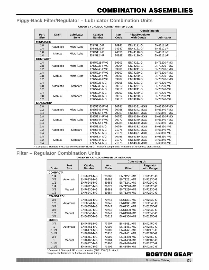
Piggy-Back Filter/Regulator – Lubricator Combination Units
Consisting of:Port Drain Lubricator Catalog Item Filter/RegulatorSize Style Number Code with Gauge Lubricator
MINIATURE1/8 Automatic Micro-Lube EN45115-F 74941 EN44111-G EN43111-F1/4 EN45125-F 74942 EN44121-G EN43121-F1/8 Manual Micro-Lube EN45114-F 74851 EN44110-G EN43111-F1/4 EN45124-F 74888 EN44120-G EN43121-F
COMPACT*1/4 EN75225-FMG 39903 EN74221-G EN73220-FMG3/8 Automatic Micro-Lube EN75235-FMG 39904 EN74231-G EN73230-FMG1/2 EN75245-FMG 39906 EN74241-G EN73240-FMG1/4 EN75224-FMG 39902 EN74220-G EN73220-FMG3/8 Manual Micro-Lube EN75234-FMG 39905 EN74230-G EN73230-FMG1/2 EN75244-FMG 39907 EN74240-G EN73240-FMG1/4 EN75225-MG 39908 EN74221-G EN73220-MG3/8 Automatic Standard EN75235-MG 39910 EN74231-G EN73230-MG1/2 EN75245-MG 39911 EN74241-G EN73240-MG1/4 EN75224-MG 39909 EN74220-G EN73220-MG3/8 Manual Standard EN75234-MG 39912 EN74230-G EN73230-MG1/2 EN75244-MG 39913 EN74240-G EN73240-MG
STANDARD*3/8 EN65335-FMG 70741 EN64331-MGG EN63330-FMG1/2 Automatic Micro-Lube EN65345-FMG 70758 EN64341-MGG EN63340-FMG3/4 EN65355-FMG 70769 EN64351-MGG EN63350-FMG3/8 EN65334-FMG 70752 EN64330-MGG EN63330-FMG1/2 Manual Micro-Lube EN65344-FMG 70772 EN64340-MGG EN63340-FMG3/4 EN65354-FMG 70781 EN64350-MGG EN63350-FMG3/8 EN65335-MG 70754 EN64331-MGG EN63330-MG1/2 Automatic Standard EN65345-MG 71075 EN64341-MGG EN63340-MG3/4 EN65355-MG 71076 EN64351-MGG EN63350-MG3/8 EN65334-MG 70756 EN64330-MGG EN63330-MG1/2 Manual Standard EN65344-MG 71077 EN64340-MGG EN63340-MG3/4 EN65354-MG 71078 EN64350-MGG EN63350-MG
ORDER BY CATALOG NUMBER OR ITEM CODE
Filter – Regulator Combination Units
Consisting of:Port Catalog Item Regulator
Drain Size Number Code Filter with Gauge
COMPACT*1/4 EN76221-MG 39880 EN71221-MG EN72220-G3/8 Automatic EN76231-MG 39882 EN71231-MG EN72230-G1/2 EN76241-MG 39883 EN71241-MG EN72240-G1/4 EN76220-MG 39879 EN71220-MG EN72220-G3/8 Manual EN76230-MG 39881 EN71230-MG EN72230-G1/2 EN76240-MG 39884 EN71240-MG EN72240-G
STANDARD*3/8 EN66331-MG 70745 EN61331-MG EN62330-G1/2 Automatic EN66341-MG 70746 EN61341-MG EN62340-G3/4 EN66351-MG 70747 EN61351-MG EN62350-G3/8 EN66330-MG 70748 EN61330-MG EN62330-G1/2 Manual EN66340-MG 70749 EN61340-MG EN62340-G3/4 EN66350-MG 70813 EN61350-MG EN62350-G
JUMBO3/4 EN46451-MG 73907 EN41451-MG EN42450-G1 Automatic EN46461-MG 73908 EN41461-MG EN42460-G
1-1/4 EN46471-MG 73909 EN41471-MG EN42470-G1-1/2 EN46481-MG 73910 EN41481-MG EN42480-G3/4 EN46450-MG 73903 EN41450-MG EN42450-G1 Manual EN46460-MG 73904 EN41460-MG EN42460-G
1-1/4 EN46470-MG 73905 EN41470-MG EN42470-G1-1/2 EN46480-MG 73906 EN41480-MG EN42480-G
* Compact & Standard FRL’s use connector (EN61308-C) To attach components, Miniature or Jumbo use brass fittings.
* Compact & Standard FRL’s use connector (EN61308-C) To attachcomponents, Miniature or Jumbo use brass fittings.
24 Fluid Power Catalog
COMBINATION ASSEMBLIES
ORDER BY CATALOG NUMBER OR ITEM CODE
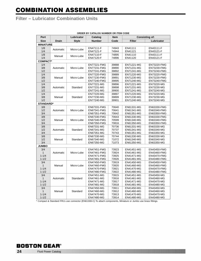
Filter – Lubricator Combination Units
Port Lubricator Catalog Item Consisting of:Size Drain Style Number Code Filter Lubricator
MINIATURE1/8 Automatic Micro-Lube EN47111-F 74943 EN41111 EN43111-F1/4 EN47121-F 74944 EN41121 EN43121-F1/8 Manual Micro-Lube EN47110-F 74895 EN41110 EN43111-F1/4 EN47120-F 74896 EN41120 EN43121-F
COMPACT*1/4 EN77221-FMG 39888 EN71221-MG EN73220-FMG3/8 Automatic Micro-Lube EN77231-FMG 39890 EN71231-MG EN73230-FMG1/2 EN77241-FMG 39892 EN71241-MG EN73240-FMG1/4 EN77220-FMG 39889 EN71220-MG EN73220-FMG3/8 Manual Micro-Lube EN77230-FMG 39891 EN71230-MG EN73230-FMG1/2 EN77240-FMG 39895 EN71240-MG EN73240-FMG1/4 EN77221-MG 39896 EN71221-MG EN73220-MG3/8 Automatic Standard EN77231-MG 39898 EN71231-MG EN73230-MG1/2 EN77241-MG 39900 EN71241-MG EN73240-MG1/4 EN77220-MG 39897 EN71220-MG EN73220-MG3/8 Manual Standard EN77230-MG 39899 EN71230-MG EN73230-MG1/2 EN77240-MG 39901 EN71240-MG EN73240-MG
STANDARD*3/8 EN67331-FMG 70640 EN61331-MG EN63330-FMG1/2 Automatic Micro-Lube EN67341-FMG 70641 EN61341-MG EN63340-FMG3/4 EN67351-FMG 70642 EN61351-MG EN63350-FMG3/8 EN67330-FMG 70643 EN61330-MG EN63330-FMG1/2 Manual Micro-Lube EN67340-FMG 70599 EN61340-MG EN63340-FMG3/4 EN67350-FMG 70816 EN61350-MG EN63350-FMG3/8 EN67331-MG 70736 EN61331-MG EN63330-MG1/2 Automatic Standard EN67341-MG 70737 EN61341-MG EN63340-MG3/4 EN67351-MG 70743 EN61351-MG EN63350-MG3/8 EN67330-MG 70744 EN61330-MG EN63330-MG1/2 Manual Standard EN67340-MG 71072 EN61340-MG EN63340-MG3/4 EN67350-MG 71073 EN61350-MG EN63350-MG
JUMBO3/4 EN47451-FMG 73923 EN41451-MG EN43450-FMG1 Automatic Micro-Lube EN47461-FMG 73924 EN41461-MG EN43460-FMG
1-1/4 EN47471-FMG 73925 EN41471-MG EN43470-FMG1-1/2 EN47481-FMG 73926 EN41481-MG EN43480-FMG3/4 EN47450-FMG 73919 EN41450-MG EN43450-FMG1 Manual Micro-Lube EN47460-FMG 73920 EN41460-MG EN43460-FMG
1-1/4 EN47470-FMG 73921 EN41470-MG EN43470-FMG1-1/2 EN47480-FMG 73922 EN41480-MG EN43480-FMG3/4 EN47451-MG 73915 EN41451-MG EN43450-MG1 Automatic Standard EN47461-MG 73916 EN41461-MG EN43460-MG
1-1/4 EN47471-MG 73917 EN41471-MG EN43470-MG1-1/2 EN47481-MG 73918 EN41481-MG EN43480-MG3/4 EN47450-MG 73911 EN41450-MG EN43450-MG1 Manual Standard EN47460-MG 73912 EN41460-MG EN43460-MG
1-1/4 EN47470-MG 73913 EN41470-MG EN43470-MG1-1/2 EN47480-MG 73914 EN41480-MG EN43480-MG
* Compact & Standard FRL’s use connector (EN61308-C) To attach components, Miniature or Jumbo use brass fittings.
Fluid Power Catalog 25
CYLINDERS
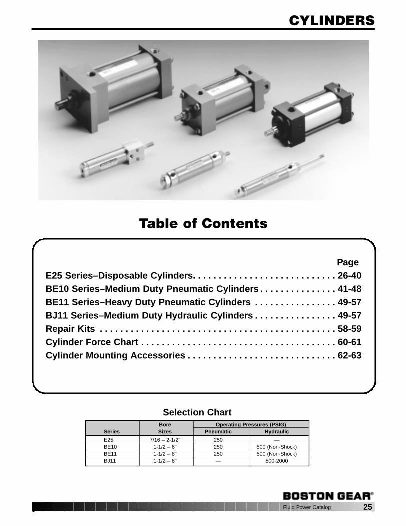
Page E25 Series–Disposable Cylinders. . . . . . . . . . . . . . . . . . . . . . . . . . . . 26-40BE10 Series–Medium Duty Pneumatic Cylinders . . . . . . . . . . . . . . . 41-48BE11 Series–Heavy Duty Pneumatic Cylinders . . . . . . . . . . . . . . . . 49-57BJ11 Series–Medium Duty Hydraulic Cylinders . . . . . . . . . . . . . . . . 49-57Repair Kits . . . . . . . . . . . . . . . . . . . . . . . . . . . . . . . . . . . . . . . . . . . . . . 58-59Cylinder Force Chart . . . . . . . . . . . . . . . . . . . . . . . . . . . . . . . . . . . . . . 60-61Cylinder Mounting Accessories . . . . . . . . . . . . . . . . . . . . . . . . . . . . . 62-63
Selection ChartBore Operating Pressures (PSIG)
Series Sizes Pneumatic Hydraulic
E25 7/16 – 2-1/2" 250 —BE10 1-1/2 – 6" 250 500 (Non-Shock)BE11 1-1/2 – 8" 250 500 (Non-Shock)BJ11 1-1/2 – 8" — 500-2000
Table of Contents
26 Fluid Power Catalog
DISPOSABLE CYLINDERS
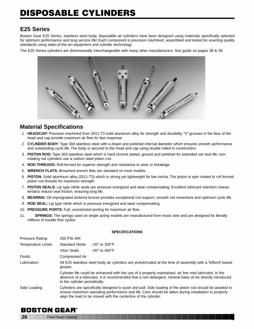
E25 SeriesBoston Gear E25 Series, stainless steel body, disposable air cylinders have been designed using materials specifically selectedfor optimum performance and long service life! Each component is precision machined, assembled and tested for exacting qualitystandards using state-of-the-art equipment and cylinder technology.
The E25 Series cylinders are dimensionally interchangeable with many other manufacturers. See guide on pages 38 & 39.
Material Specifications1. HEAD/CAP: Precision machined from 2011-T3 solid aluminum alloy for strength and durability. “V” grooves in the face of the
head and cap provide maximum air flow for fast response.
2. CYLINDER BODY: Type 304 stainless steel with a drawn and polished internal diameter which ensures smooth performanceand outstanding cycle life. The body is secured to the head and cap using double rolled in construction.
3. PISTON ROD: Type 303 stainless steel which is hard chrome plated, ground and polished for extended rod seal life; non-rotating rod cylinders use a carbon steel piston rod.
4. ROD THREADS: Roll-formed for superior strength and resistance to wear or breakage.
5. WRENCH FLATS: Broached wrench flats are standard on most models.
6. PISTON: Solid aluminum alloy (2011-T3) which is strong yet lightweight for low inertia. The piston is spin riveted to roll formedpiston rod threads for maximum strength.
7. PISTON SEALS: Lip type nitrile seals are pressure energized and wear compensating. Excellent lubricant retention charac-teristics reduce seal friction, ensuring long life.
8. BEARING: Oil impregnated sintered bronze provides exceptional rod support, smooth rod movement and optimum cycle life.
9. ROD SEAL: Lip type nitrile which is pressure energized and wear compensating.
10. PRESSURE PORTS: Full, unrestricted porting for maximum air flow.
11. SPRINGS: The springs used on single acting models are manufactured from music wire and are designed for literallymillions of trouble free cycles.
SPECIFICATIONS
Pressure Rating: 250 PSI AIR
Temperature Limits: Standard Nitrile –20° to 200°F
Viton Seals –50° to 450°F
Fluids: Compressed Air
Lubrication: All E25 stainless steel body air cylinders are prelubricated at the time of assembly with a Teflon® basedgrease.
Cylinder life could be enhanced with the use of a properly maintained, air line mist lubricator. In theabsence of a lubricator, it is recommended that a non-detergent, mineral base oil be directly introducedto the cylinder periodically.
Side Loading: Cylinders are specifically designed to push and pull. Side loading of the piston rod should be avoided toensure maximum operating performance and life. Care should be taken during installation to properlyalign the load to be moved with the centerline of the cylinder.
Fluid Power Catalog 27
DISPOSABLE CYLINDERS
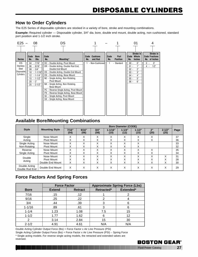
How to Order CylindersThe E25 Series of disposable cylinders are stocked in a variety of bore, stroke and mounting combinations.
Example: Required cylinder — Disposable cylinder, 3/4" dia. bore, double end mount, double acting, non cushioned, standardport position and 1-1/2 inch stroke.
Available Bore/Mounting Combinations
E25 – 08 DS 1 – 1 01 4
Series
E25Stainless
SteelDisposableCylinders
Code BoreNo. DIa.
04 - 7/16"06 - 9/16"08 - 3/4"10 - 1-1/16"12 - 1-1/4"15 - 1-1/2"20 - 2"25 - 2-1/2"
CodeNo. Mounting*
DC - Double Acting, Pivot MountDR - Double Acting, Double Rod End,
Double End MountDS - Double Acting, Double End MountDX - Double Acting, Nose MountNC - Single Acting, Non-Rotating,
Pivot MountNX - Single Acting, Non-Rotating,
Nose MountPC - Reverse Single Acting, Pivot MountPX - Reverse Single Acting, Nose MountSC - Single Acting, Pivot MountSX - Single Acting, Nose Mount
Code CushionsNo. and Rod
1 - Non-Cushioned
Code PortNo. Position
1 - Standard
Stroke inCode WholeNo. Inches
00 - 0"01 - 1"02 - 2"03 - 3"04 - 4"05 - 5"06 - 6"
Stroke inCode FractionsNo. of Inches
0 - 0"4 - 1/2"
Bore Diameter (CODE)Style Mounting Style 7/16" 9/16" 3/4" 1-1/16" 1-1/4” 1-1/2" 2" 2-1/2" Page
(04) (06) (08) (10) (12) (15) (20) (25)
Single Nose Mount X X X X X X X 37Acting Pivot Mount X X X X X X X 36
Single Acting Nose Mount X X X X X X 33Non-Rotating Pivot Mount X X X X X X 32
Reverse Nose Mount X X X X X X X 35Single Acting Pivot Mount X X X X X X X 34
Nose Mount X X X X X X X X 31DoublePivot Mount X X X X X X X X 28Acting
Double End Mount X X X X X X X X 30Double Acting
Double End Mount X X X X X X X X 29Double Rod End
Force Factors And Spring Forces
Force Factor Approximate Spring Force (Lbs)Bore Extend Retract Retracted* Extended*
7/16 .15 .12 1 29/16 .25 .22 2 43/4 .44 .39 3 6
1-1/16 .89 .61 3 61-1/4 1.23 1.08 7.5 151-1/2 1.77 1.62 6 12
2 3.14 2.84 15 302-1/2 4.91 4.61 N/A N/A
Double Acting Cylinder Output Force (lbs) = Force Factor x Air Line Pressure (PSI)Single Acting Cylinder Output Force (lbs) = Force Factor x Air Line Pressure (PSI) – Spring Force* Single acting models. For reverse single acting models, the retracted and extended valves arereversed.

28 Fluid Power Catalog
DISPOSABLE CYLINDERSDC – Double Acting, Pivot Mount E25 Series
250 PSIG Air7/16" to 2-1/2" Bore
Bore A B C D E F G H J K L M N P R S T U V X7/16 2.81 .72 .38 .50 — .05 .44 .31 10-32 .74 .18 7/16-20 — 10-32 .156 .25 2.56 7/16-20 .50 .434/.437
9/16 2.75 .75 .38 .50 — .06 .38 .31 10-32 .62 .18 7/16-20 — 10-32 .156 .25 2.56 7/16-20 .50 .434/.437
3/4 4.03 .97 .50 .50 — .09 .62 .38 1/8 NPT .86 .25 5/8-18 — 1/4-28 .250 .34 3.75 5/8-18 .75 .621/.624
1 1/16 4.12 1.07 .50 .50 .12 .09 .62 .38 1/8 NPT 1.12 .31 5/8-18 .25 5/16-24 .250 .34 3.84 5/8-18 .75 .621/.624
1 1/4 5.12 1.37 .63 .75 .25 .09 .78 .50 1/8 NPT 1.34 .43 3/4-16 .38 7/16-20 .250 .41 4.72 3/4-16 .88 .746/.749
1 1/2 4.76 1.25 .63 .75 .25 .09 .81 .62 1/8 NPT 1.56 .43 3/4-16 .38 7/16-20 .375 .50 4.38 N/A 1.00 .746/.749
2 6.06 1.46 .81 .88 .38 .12 1.03 .75 1/4 NPT 2.08 .62 1 1/4-12 .50 1/2-20 .375 .56 5.62 1 1/4-12 1.63 1.372/1.375
2 1/2 6.06 1.46 .81 .88 .38 .12 1.03 .75 1/4 NPT 2.62 .62 1 3/8-12 .50 1/2-20 .375 .56 5.62 1 3/8-12 1.63 1.497/1.500
KH
V
U MOUNTING THREADS
R DIA.PINS
G
A + STROKE
J PORT
BC
FE
D
M MOUNTING THREADSX PILOT
T + STROKE
P PISTONRODTHREADS
L DIA.PISTONRODN ACROSSWRENCHFLATS
DOUBLE ACTING
AIR
AIR PRESSURE TO EXTEND
AIR
AIR PRESSURE TO RETRACT
See page 27 for Force Factors.
ORDER BY CATALOG NUMBER OR ITEM CODE ORDER BY CATALOG NUMBER OR ITEM CODE
Boston Gear ItemBore Stroke Catalog Number Code
1/2 E25-04DC1-1004 711381 E25-04DC1-1010 71139
1 1/2 E25-04DC1-1014 711407/16 2 E25-04DC1-1020 71141
3 E25-04DC1-1030 711424 E25-04DC1-1040 711435 E25-04DC1-1050 711446 E25-04DC1-1060 71145
1/2 E25-06DC1-1004 712121 E25-06DC1-1010 71213
9/16 1 1/2 E25-06DC1-1014 712142 E25-06DC1-1020 712153 E25-06DC1-1030 712164 E25-06DC1-1040 71217
1/2 E25-08DC1-1004 713941 E25-08DC1-1010 71395
1 1/2 E25-08DC1-1014 713963/4 2 E25-08DC1-1020 71397
3 E25-08DC1-1030 714004 E25-08DC1-1040 714125 E25-08DC1-1050 714136 E25-08DC1-1060 714141 E25-10DC1-1010 715642 E25-10DC1-1020 71565
1 1/16 3 E25-10DC1-1030 715664 E25-10DC1-1040 715685 E25-10DC1-1050 715696 E25-10DC1-1060 71570
Boston Gear ItemBore Stroke Catalog Number Code
1 E25-12DC1-1010 716862 E25-12DC1-1020 71687
1 1/4 3 E25-12DC1-1030 716894 E25-12DC1-1040 716905 E25-12DC1-1050 716916 E25-12DC1-1060 716961 E25-15DC1-1010 717832 E25-15DC1-1020 71784
1 1/2 3 E25-15DC1-1030 717884 E25-15DC1-1040 717895 E25-15DC1-1050 717906 E25-15DC1-1060 717911 E25-20DC1-1010 730242 E25-20DC1-1020 73025
2 3 E25-20DC1-1030 730294 E25-20DC1-1040 730305 E25-20DC1-1050 730326 E25-20DC1-1060 730341 E25-25DC1-1010 730862 E25-25DC1-1020 73087
2 1/2 3 E25-25DC1-1030 730884 E25-25DC1-1040 730895 E25-25DC1-1050 730906 E25-25DC1-1060 73091
ALL DIMENSIONS IN INCHES
Fluid Power Catalog 29
DISPOSABLE CYLINDERS
P PISTONRODTHREADS
L DIA.PISTONROD
N ACROSSWRENCHFLATS
D
E
B
C
F
K DIA.
J PORTS
X PILOTM MOUNTING NUTS
A + 2 X STROKE
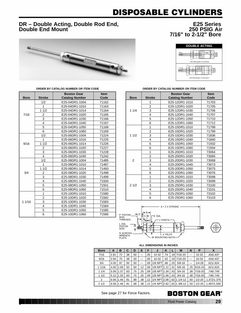
DR – Double Acting, Double Rod End, E25 SeriesDouble End Mount 250 PSIG Air
7/16" to 2-1/2" Bore
Bore A B C D E F J K L M N P X7/16 2.81 .72 .38 .50 — .05 10-32 .74 .19 7/16-20 — 10-32 .434/.437
9/16 2.94 .75 .38 .50 — .06 10-32 .62 .19 7/16-20 — 10-32 .434/.437
3/4 4.00 .97 .50 .50 — .09 1/8 NPT .86 .25 5/8-18 — 1/4-28 .621/.624
1 1/16 4.00 1.06 .50 .50 .12 .09 1/8 NPT 1.12 .31 5/8-18 .25 5/16-24 .621/.624
1 1/4 5.56 1.37 .63 .75 .25 .09 1/8 NPT 1.34 .43 3/4-16 .38 7/16-20 .746/.749
1 1/2 5.12 1.25 .63 .75 .25 .09 1/8 NPT 1.56 .43 3/4-16 .38 7/16-20 .746/.749
2 6.56 1.46 .81 .88 .38 .12 1/4 NPT 2.08 .62 1 1/4-12 .50 1/2-20 1.372/1.375
2 1/2 6.56 1.46 .81 .88 .38 .12 1/4 NPT 2.62 .62 1 3/8-12 .50 1/2-20 1.497/1.500
DOUBLE ACTING
AIR
AIR PRESSURE TO EXTEND
AIR
AIR PRESSURE TO RETRACT
See page 27 for Force Factors.
ORDER BY CATALOG NUMBER OR ITEM CODE ORDER BY CATALOG NUMBER OR ITEM CODE
Boston Gear ItemBore Stroke Catalog Number Code
1/2 E25-04DR1-1004 711621 E25-04DR1-1010 71163
1 1/2 E25-04DR1-1014 711647/16 2 E25-04DR1-1020 71165
3 E25-04DR1-1030 711664 E25-04DR1-1040 711675 E25-04DR1-1050 711686 E25-04DR1-1060 71169
1/2 E25-06DR1-1004 712241 E25-06DR1-1010 71225
9/16 1 1/2 E25-06DR1-1014 712262 E25-06DR1-1020 712273 E25-06DR1-1030 712284 E25-06DR1-1040 71242
1/2 E25-08DR1-1004 714851 E25-08DR1-1010 71487
1 1/2 E25-08DR1-1014 714933/4 2 E25-08DR1-1020 71498
3 E25-08DR1-1030 714994 E25-08DR1-1040 715005 E25-08DR1-1050 715016 E25-08DR1-1060 715101 E25-10DR1-1010 715802 E25-10DR1-1020 71582
1 1/16 3 E25-10DR1-1030 715834 E25-10DR1-1040 715845 E25-10DR1-1050 715856 E25-10DR1-1060 71586
Boston Gear ItemBore Stroke Catalog Number Code
1 E25-12DR1-1010 717032 E25-12DR1-1020 71705
1 1/4 3 E25-12DR1-1030 717064 E25-12DR1-1040 717075 E25-12DR1-1050 717106 E25-12DR1-1060 717121 E25-15DR1-1010 717982 E25-15DR1-1020 71799
1 1/2 3 E25-15DR1-1030 718364 E25-15DR1-1040 718405 E25-15DR1-1050 719326 E25-15DR1-1060 719341 E25-20DR1-1010 730642 E25-20DR1-1020 73065
2 3 E25-20DR1-1030 730684 E25-20DR1-1040 730735 E25-20DR1-1050 730756 E25-20DR1-1060 730761 E25-25DR1-1010 730982 E25-25DR1-1020 73099
2 1/2 3 E25-25DR1-1030 731004 E25-25DR1-1040 731015 E25-25DR1-1050 731026 E25-25DR1-1060 73103
ALL DIMENSIONS IN INCHES
30 Fluid Power Catalog
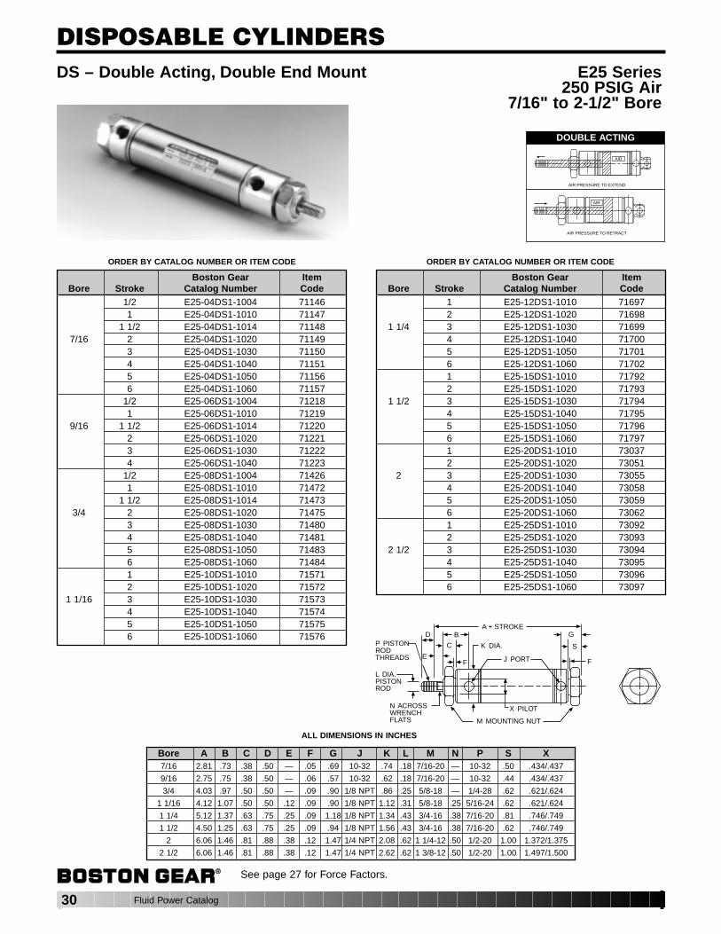
DISPOSABLE CYLINDERSDS – Double Acting, Double End Mount E25 Series
250 PSIG Air7/16" to 2-1/2" Bore
Bore A B C D E F G J K L M N P S X7/16 2.81 .73 .38 .50 — .05 .69 10-32 .74 .18 7/16-20 — 10-32 .50 .434/.437
9/16 2.75 .75 .38 .50 — .06 .57 10-32 .62 .18 7/16-20 — 10-32 .44 .434/.437
3/4 4.03 .97 .50 .50 — .09 .90 1/8 NPT .86 .25 5/8-18 — 1/4-28 .62 .621/.624
1 1/16 4.12 1.07 .50 .50 .12 .09 .90 1/8 NPT 1.12 .31 5/8-18 .25 5/16-24 .62 .621/.624
1 1/4 5.12 1.37 .63 .75 .25 .09 1.18 1/8 NPT 1.34 .43 3/4-16 .38 7/16-20 .81 .746/.749
1 1/2 4.50 1.25 .63 .75 .25 .09 .94 1/8 NPT 1.56 .43 3/4-16 .38 7/16-20 .62 .746/.749
2 6.06 1.46 .81 .88 .38 .12 1.47 1/4 NPT 2.08 .62 1 1/4-12 .50 1/2-20 1.00 1.372/1.375
2 1/2 6.06 1.46 .81 .88 .38 .12 1.47 1/4 NPT 2.62 .62 1 3/8-12 .50 1/2-20 1.00 1.497/1.500
A + STROKE
P PISTONRODTHREADS
L DIA.PISTONROD
N ACROSSWRENCHFLATS
D
E
C
B
F
M MOUNTING NUT
X PILOT
J PORT
K DIA.
G
S
F
DOUBLE ACTING
AIR
AIR PRESSURE TO EXTEND
AIR
AIR PRESSURE TO RETRACT
ORDER BY CATALOG NUMBER OR ITEM CODE ORDER BY CATALOG NUMBER OR ITEM CODE
Boston Gear ItemBore Stroke Catalog Number Code
1/2 E25-04DS1-1004 711461 E25-04DS1-1010 71147
1 1/2 E25-04DS1-1014 711487/16 2 E25-04DS1-1020 71149
3 E25-04DS1-1030 711504 E25-04DS1-1040 711515 E25-04DS1-1050 711566 E25-04DS1-1060 71157
1/2 E25-06DS1-1004 712181 E25-06DS1-1010 71219
9/16 1 1/2 E25-06DS1-1014 712202 E25-06DS1-1020 712213 E25-06DS1-1030 712224 E25-06DS1-1040 71223
1/2 E25-08DS1-1004 714261 E25-08DS1-1010 71472
1 1/2 E25-08DS1-1014 714733/4 2 E25-08DS1-1020 71475
3 E25-08DS1-1030 714804 E25-08DS1-1040 714815 E25-08DS1-1050 714836 E25-08DS1-1060 714841 E25-10DS1-1010 715712 E25-10DS1-1020 71572
1 1/16 3 E25-10DS1-1030 715734 E25-10DS1-1040 715745 E25-10DS1-1050 715756 E25-10DS1-1060 71576
Boston Gear ItemBore Stroke Catalog Number Code
1 E25-12DS1-1010 716972 E25-12DS1-1020 71698
1 1/4 3 E25-12DS1-1030 716994 E25-12DS1-1040 717005 E25-12DS1-1050 717016 E25-12DS1-1060 717021 E25-15DS1-1010 717922 E25-15DS1-1020 71793
1 1/2 3 E25-15DS1-1030 717944 E25-15DS1-1040 717955 E25-15DS1-1050 717966 E25-15DS1-1060 717971 E25-20DS1-1010 730372 E25-20DS1-1020 73051
2 3 E25-20DS1-1030 730554 E25-20DS1-1040 730585 E25-20DS1-1050 730596 E25-20DS1-1060 730621 E25-25DS1-1010 730922 E25-25DS1-1020 73093
2 1/2 3 E25-25DS1-1030 730944 E25-25DS1-1040 730955 E25-25DS1-1050 730966 E25-25DS1-1060 73097
See page 27 for Force Factors.
ALL DIMENSIONS IN INCHES
Fluid Power Catalog 31
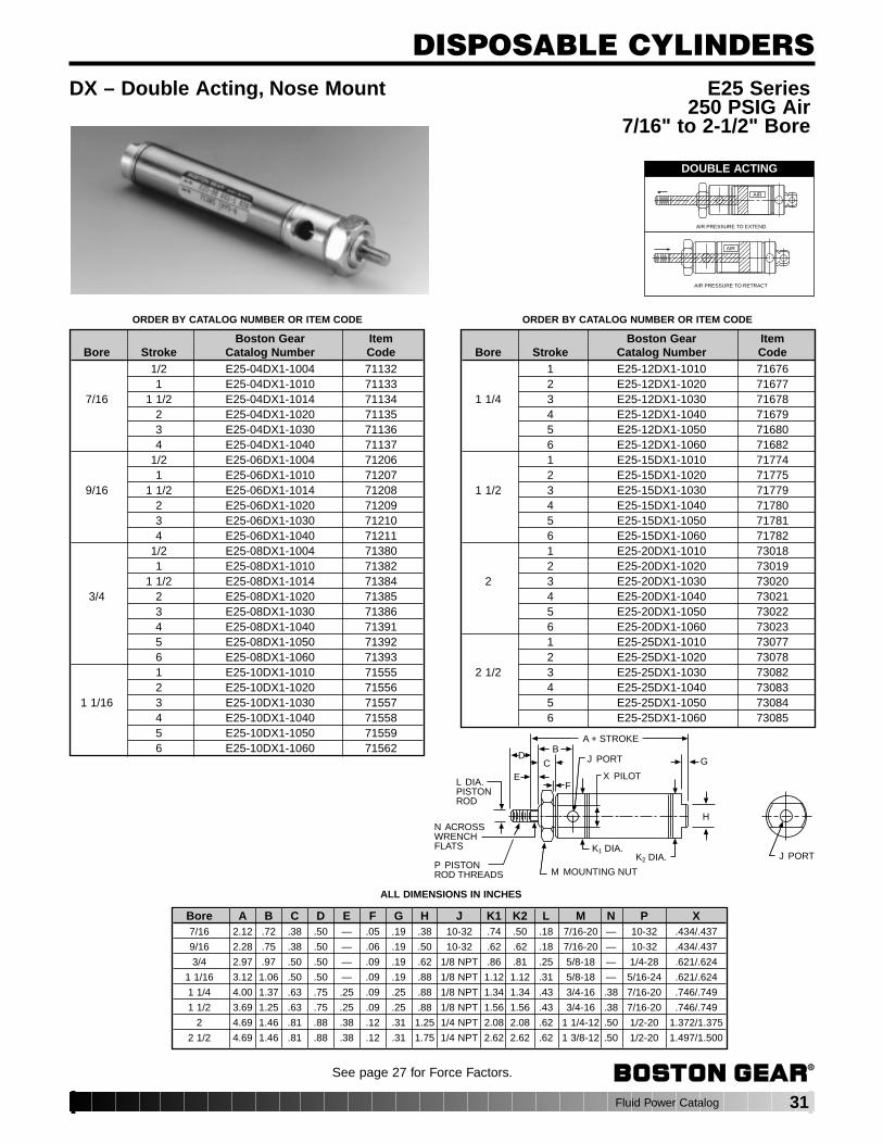
DISPOSABLE CYLINDERSDX – Double Acting, Nose Mount E25 Series
250 PSIG Air7/16" to 2-1/2" Bore
Bore A B C D E F G H J K1 K2 L M N P X7/16 2.12 .72 .38 .50 — .05 .19 .38 10-32 .74 .50 .18 7/16-20 — 10-32 .434/.437
9/16 2.28 .75 .38 .50 — .06 .19 .50 10-32 .62 .62 .18 7/16-20 — 10-32 .434/.437
3/4 2.97 .97 .50 .50 — .09 .19 .62 1/8 NPT .86 .81 .25 5/8-18 — 1/4-28 .621/.624
1 1/16 3.12 1.06 .50 .50 — .09 .19 .88 1/8 NPT 1.12 1.12 .31 5/8-18 — 5/16-24 .621/.624
1 1/4 4.00 1.37 .63 .75 .25 .09 .25 .88 1/8 NPT 1.34 1.34 .43 3/4-16 .38 7/16-20 .746/.749
1 1/2 3.69 1.25 .63 .75 .25 .09 .25 .88 1/8 NPT 1.56 1.56 .43 3/4-16 .38 7/16-20 .746/.749
2 4.69 1.46 .81 .88 .38 .12 .31 1.25 1/4 NPT 2.08 2.08 .62 1 1/4-12 .50 1/2-20 1.372/1.375
2 1/2 4.69 1.46 .81 .88 .38 .12 .31 1.75 1/4 NPT 2.62 2.62 .62 1 3/8-12 .50 1/2-20 1.497/1.500
J PORT
M MOUNTING NUTP PISTONROD THREADS
N ACROSSWRENCHFLATS
L DIA.PISTONROD
X PILOT
A + STROKE
J PORT G
H
FE
DC
B
K1 DIA.K2 DIA.
DOUBLE ACTING
AIR
AIR PRESSURE TO EXTEND
AIR
AIR PRESSURE TO RETRACT
ORDER BY CATALOG NUMBER OR ITEM CODE ORDER BY CATALOG NUMBER OR ITEM CODE
Boston Gear ItemBore Stroke Catalog Number Code
1/2 E25-04DX1-1004 711321 E25-04DX1-1010 71133
7/16 1 1/2 E25-04DX1-1014 711342 E25-04DX1-1020 711353 E25-04DX1-1030 711364 E25-04DX1-1040 71137
1/2 E25-06DX1-1004 712061 E25-06DX1-1010 71207
9/16 1 1/2 E25-06DX1-1014 712082 E25-06DX1-1020 712093 E25-06DX1-1030 712104 E25-06DX1-1040 71211
1/2 E25-08DX1-1004 713801 E25-08DX1-1010 71382
1 1/2 E25-08DX1-1014 713843/4 2 E25-08DX1-1020 71385
3 E25-08DX1-1030 713864 E25-08DX1-1040 713915 E25-08DX1-1050 713926 E25-08DX1-1060 713931 E25-10DX1-1010 715552 E25-10DX1-1020 71556
1 1/16 3 E25-10DX1-1030 715574 E25-10DX1-1040 715585 E25-10DX1-1050 715596 E25-10DX1-1060 71562
Boston Gear ItemBore Stroke Catalog Number Code
1 E25-12DX1-1010 716762 E25-12DX1-1020 71677
1 1/4 3 E25-12DX1-1030 716784 E25-12DX1-1040 716795 E25-12DX1-1050 716806 E25-12DX1-1060 716821 E25-15DX1-1010 717742 E25-15DX1-1020 71775
1 1/2 3 E25-15DX1-1030 717794 E25-15DX1-1040 717805 E25-15DX1-1050 717816 E25-15DX1-1060 717821 E25-20DX1-1010 730182 E25-20DX1-1020 73019
2 3 E25-20DX1-1030 730204 E25-20DX1-1040 730215 E25-20DX1-1050 730226 E25-20DX1-1060 730231 E25-25DX1-1010 730772 E25-25DX1-1020 73078
2 1/2 3 E25-25DX1-1030 730824 E25-25DX1-1040 730835 E25-25DX1-1050 730846 E25-25DX1-1060 73085
See page 27 for Force Factors.
ALL DIMENSIONS IN INCHES
32 Fluid Power Catalog
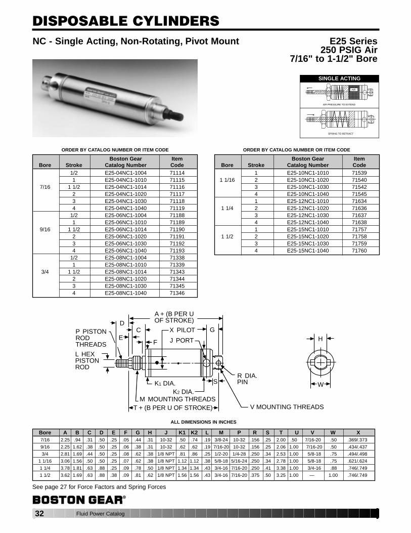
DISPOSABLE CYLINDERSNC - Single Acting, Non-Rotating, Pivot Mount E25 Series
250 PSIG Air7/16" to 1-1/2" Bore
Bore A B C D E F G H J K1 K2 L M P R S T U V W X7/16 2.25 .94 .31 .50 .25 .05 .44 .31 10-32 .50 .74 .19 3/8-24 10-32 .156 .25 2.00 .50 7/16-20 .50 .369/.373
9/16 2.25 1.62 .38 .50 .25 .06 .38 .31 10-32 .62 .62 .19 7/16-20 10-32 .156 .25 2.06 1.00 7/16-20 .50 .434/.437
3/4 2.81 1.69 .44 .50 .25 .08 .62 .38 1/8 NPT .81 .86 .25 1/2-20 1/4-28 .250 .34 2.53 1.00 5/8-18 .75 .494/.498
1 1/16 3.06 1.56 .50 .50 .25 .07 .62 .38 1/8 NPT 1.12 1.12 .38 5/8-18 5/16-24 .250 .34 2.78 1.00 5/8-18 .75 .621/.624
1 1/4 3.78 1.81 .63 .88 .25 .09 .78 .50 1/8 NPT 1.34 1.34 .43 3/4-16 7/16-20 .250 .41 3.38 1.00 3/4-16 .88 .746/.749
1 1/2 3.62 1.69 .63 .88 .38 .09 .81 .62 1/8 NPT 1.56 1.56 .43 3/4-16 7/16-20 .375 .50 3.25 1.00 — 1.00 .746/.749
A + (B PER U OF STROKE)
X PILOT
J PORT
G
S
C
FE
D
M MOUNTING THREADST + (B PER U OF STROKE)
K1 DIA.K2 DIA.
R DIA.PIN
V MOUNTING THREADS
P PISTONRODTHREADS
L HEXPISTONROD
W
H
SINGLE ACTING
AIR
AIR PRESSURE TO EXTEND
SPRING TO RETRACT
See page 27 for Force Factors and Spring Forces
ORDER BY CATALOG NUMBER OR ITEM CODE
Boston Gear ItemBore Stroke Catalog Number Code
1 E25-10NC1-1010 715391 1/16 2 E25-10NC1-1020 71540
3 E25-10NC1-1030 715424 E25-10NC1-1040 715451 E25-12NC1-1010 71634
1 1/4 2 E25-12NC1-1020 716363 E25-12NC1-1030 716374 E25-12NC1-1040 716381 E25-15NC1-1010 71757
1 1/2 2 E25-15NC1-1020 717583 E25-15NC1-1030 717594 E25-15NC1-1040 71760
ORDER BY CATALOG NUMBER OR ITEM CODE
Boston Gear ItemBore Stroke Catalog Number Code
1/2 E25-04NC1-1004 711141 E25-04NC1-1010 71115
7/16 1 1/2 E25-04NC1-1014 711162 E25-04NC1-1020 711173 E25-04NC1-1030 711184 E25-04NC1-1040 71119
1/2 E25-06NC1-1004 711881 E25-06NC1-1010 71189
9/16 1 1/2 E25-06NC1-1014 711902 E25-06NC1-1020 711913 E25-06NC1-1030 711924 E25-06NC1-1040 71193
1/2 E25-08NC1-1004 713381 E25-08NC1-1010 71339
3/4 1 1/2 E25-08NC1-1014 713432 E25-08NC1-1020 713443 E25-08NC1-1030 713454 E25-08NC1-1040 71346
ALL DIMENSIONS IN INCHES
Fluid Power Catalog 33
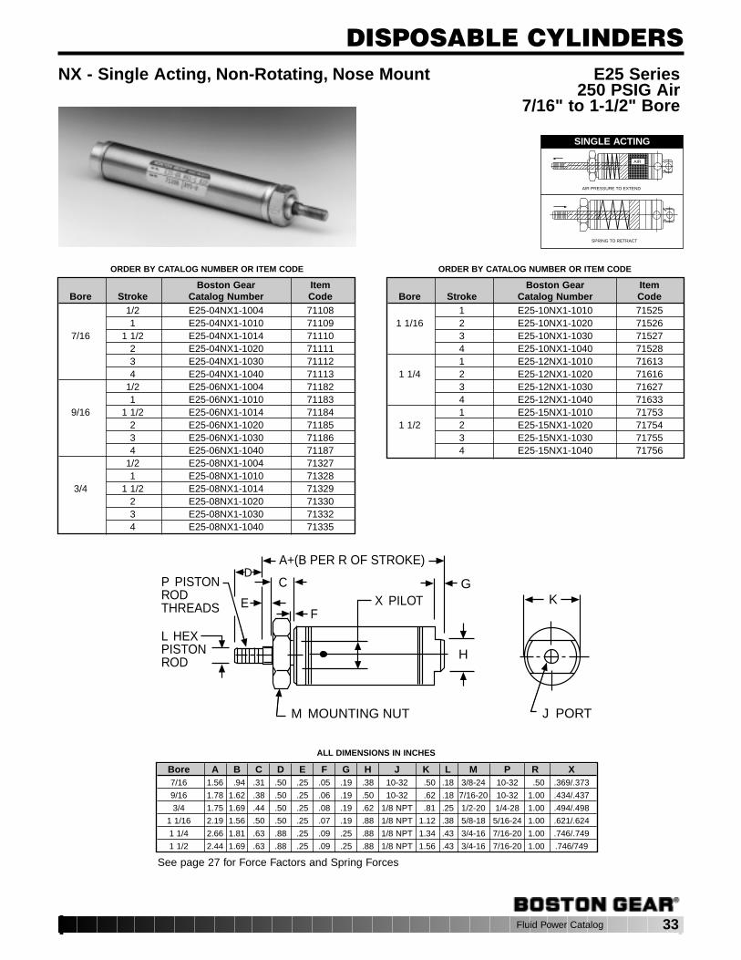
DISPOSABLE CYLINDERSNX - Single Acting, Non-Rotating, Nose Mount E25 Series
250 PSIG Air7/16" to 1-1/2" Bore
Bore A B C D E F G H J K L M P R X7/16 1.56 .94 .31 .50 .25 .05 .19 .38 10-32 .50 .18 3/8-24 10-32 .50 .369/.373
9/16 1.78 1.62 .38 .50 .25 .06 .19 .50 10-32 .62 .18 7/16-20 10-32 1.00 .434/.437
3/4 1.75 1.69 .44 .50 .25 .08 .19 .62 1/8 NPT .81 .25 1/2-20 1/4-28 1.00 .494/.498
1 1/16 2.19 1.56 .50 .50 .25 .07 .19 .88 1/8 NPT 1.12 .38 5/8-18 5/16-24 1.00 .621/.624
1 1/4 2.66 1.81 .63 .88 .25 .09 .25 .88 1/8 NPT 1.34 .43 3/4-16 7/16-20 1.00 .746/.749
1 1/2 2.44 1.69 .63 .88 .25 .09 .25 .88 1/8 NPT 1.56 .43 3/4-16 7/16-20 1.00 .746/749
M MOUNTING NUT
H
A+(B PER R OF STROKE)D
C
FX PILOTE
P PISTONRODTHREADS
L HEXPISTONROD
G
J PORT
K
SINGLE ACTING
AIR
AIR PRESSURE TO EXTEND
SPRING TO RETRACT
ORDER BY CATALOG NUMBER OR ITEM CODE ORDER BY CATALOG NUMBER OR ITEM CODE
Boston Gear ItemBore Stroke Catalog Number Code
1/2 E25-04NX1-1004 711081 E25-04NX1-1010 71109
7/16 1 1/2 E25-04NX1-1014 711102 E25-04NX1-1020 711113 E25-04NX1-1030 711124 E25-04NX1-1040 71113
1/2 E25-06NX1-1004 711821 E25-06NX1-1010 71183
9/16 1 1/2 E25-06NX1-1014 711842 E25-06NX1-1020 711853 E25-06NX1-1030 711864 E25-06NX1-1040 71187
1/2 E25-08NX1-1004 713271 E25-08NX1-1010 71328
3/4 1 1/2 E25-08NX1-1014 713292 E25-08NX1-1020 713303 E25-08NX1-1030 713324 E25-08NX1-1040 71335
Boston Gear ItemBore Stroke Catalog Number Code
1 E25-10NX1-1010 715251 1/16 2 E25-10NX1-1020 71526
3 E25-10NX1-1030 715274 E25-10NX1-1040 715281 E25-12NX1-1010 71613
1 1/4 2 E25-12NX1-1020 716163 E25-12NX1-1030 716274 E25-12NX1-1040 716331 E25-15NX1-1010 71753
1 1/2 2 E25-15NX1-1020 717543 E25-15NX1-1030 717554 E25-15NX1-1040 71756
See page 27 for Force Factors and Spring Forces
ALL DIMENSIONS IN INCHES

34 Fluid Power Catalog
DISPOSABLE CYLINDERS
2" BORE ONLYSTROKE A + (B Per R of Stroke)
1 8.05
2 11.05
3 13.28
4 17.28
PC – Reverse Single Acting, Pivot Mount E25 Series250 PSIG Air
7/16" to 2" Bore
Bore A B C D E F G H J K L M N P R S T U V X
7/16 2.38 1.44 .38 .50 — .05 .72 .31 10-32 .74 .19 7/16-20 — 10-32 .50 .25 .25 .156 .50 .434/.437
9/16 2.28 2.62 .38 .50 — .06 .75 .31 10-32 .62 .19 7/16-20 — 10-32 1.00 .25 .19 .156 .50 .434/437
3/4 2.44 2.69 .50 .50 — .09 .97 .38 1/8 NPT .86 .25 5/8-18 — 1/4-28 1.00 .34 .28 .250 .75 .621/.624
1 1/16 2.78 2.81 .50 .50 .12 .09 1.06 .38 1/8 NPT 1.12 .31 5/8-18 .25 5/16-24 1.00 .34 .28 .250 .75 .621/.624
1 1/4 3.78 2.81 .63 .75 .25 .09 1.37 .50 1/8 NPT 1.34 .44 3/4-16 .38 7/16-20 1.00 .34 .38 .250 1.34 .746/.749
1 1/2 3.88 3.00 .63 1.25 .25 .09 1.25 .62 1/8 NPT 1.56 .44 3/4-16 .38 7/16-20 1.00 .50 .38 .375 1.00 .746/.749
2 * * .81 .88 .38 .12 1.46 .75 1/4 NPT 2.08 .62 1 1/4-12 .50 1/2-20 * .56 .44 .375 1.63 1.372/1.375
CG
F
DA + (B PER R OF STROKE)
E
P PISTONRODTHREADS
L DIA.PISTONROD
N ACROSSWRENCHFLATS
J PORT
X PILOTM MOUNTING THREADS
S
T
U DIA.PIN V
HK
REVERSE SINGLE ACTING
SPRING TO EXTEND
AIR PRESSURE TO RETRACT
AIR
*See chart above.
See page 27 for Force Factors and Spring Forces
ORDER BY CATALOG NUMBER OR ITEM CODE ORDER BY CATALOG NUMBER OR ITEM CODE
Boston Gear ItemBore Stroke Catalog Number Code
1/2 E25-04PC1-1004 711261 E25-04PC1-1010 71127
7/16 1 1/2 E25-04PC1-1014 711282 E25-04PC1-1020 711293 E25-04PC1-1030 711304 E25-04PC1-1040 71131
1/2 E25-06PC1-1004 712001 E25-06PC1-1010 71201
9/16 1 1/2 E25-06PC1-1014 712022 E25-06PC1-1020 712033 E25-06PC1-1030 712044 E25-06PC1-1040 71205
1/2 E25-08PC1-1004 713581 E25-08PC1-1010 71361
3/4 1 1/2 E25-08PC1-1014 713642 E25-08PC1-1020 713673 E25-08PC1-1030 713684 E25-08PC1-1040 713731 E25-10PC1-1010 71550
1 1/16 2 E25-10PC1-1020 715513 E25-10PC1-1030 715534 E25-10PC1-1040 71554
Boston Gear ItemBore Stroke Catalog Number Code
1 E25-12PC1-1010 716481 1/4 2 E25-12PC1-1020 71651
3 E25-12PC1-1030 716634 E25-12PC1-1040 716751 E25-15PC1-1010 71768
1 1/2 2 E25-15PC1-1020 717693 E25-15PC1-1030 717704 E25-15PC1-1040 717731 E25-20PC1-1010 73014
2 2 E25-20PC1-1020 730153 E25-20PC1-1030 730164 E25-20PC1-1040 73017
ALL DIMENSIONS IN INCHES
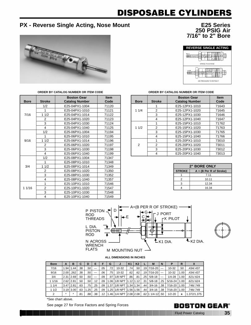
Fluid Power Catalog 35
DISPOSABLE CYLINDERS
2" BORE ONLYSTROKE A + (B Per R of Stroke)
1 7.11
2 10.11
3 12.34
4 16.34
PX - Reverse Single Acting, Nose Mount E25 Series250 PSIG Air
7/16" to 2" Bore
Bore A B C D E F G J K1 K2 L M N P R X
7/16 1.94 1.44 .38 .50 — .05 .72 10-32 .74 .50 .19 7/16-20 — 10-32 .50 .434/.437
9/16 2.00 .262 .38 .50 — .06 .75 10-32 .62 .62 .19 7/16-20 — 10-32 1.00 .434/.437
3/4 2.31 2.69 .50 .50 — .09 .97 1/8 NPT .86 .81 .25 5/8-18 — 1/4-28 1.00 .621/.624
1 1/16 2.62 2.81 .50 .50 .12 .09 1.06 1/8 NPT 1.12 1.12 .31 5/8-18 .25 5/16-24 1.00 .621/.624
1 1/4 3.47 2.81 .63 .75 .25 .09 1.37 1/8 NPT 1.34 1.34 .44 3/4-16 .38 7/16-20 1.00 .746/.749
1 1/2 3.19 3.00 .63 1.25 .25 .09 1.25 1/8 NPT 1.56 1.56 .44 3/4-16 .38 7/16-20 1.00 .746/.749
2 * * .81 .88 .38 .12 1.46 1/4 NPT 2.08 2.08 .62 1 1/4-12 .50 1/2-20 * 1.372/1.375
P PISTONRODTHREADS
L DIA.PISTONROD
N ACROSSWRENCHFLATS M MOUNTING NUT
A+(B PER R OF STROKE)
J PORTX PILOT
GC
F
D
E
K1 DIA. K2 DIA.
REVERSE SINGLE ACTING
SPRING TO EXTEND
AIR PRESSURE TO RETRACT
AIR
*See chart above.
See page 27 for Force Factors and Spring Forces
ORDER BY CATALOG NUMBER OR ITEM CODE ORDER BY CATALOG NUMBER OR ITEM CODE
Boston Gear ItemBore Stroke Catalog Number Code
1/2 E25-04PX1-1004 711201 E25-04PX1-1010 71121
7/16 1 1/2 E25-04PX1-1014 711222 E25-04PX1-1020 711233 E25-04PX1-1030 711244 E25-04PX1-1040 71125
1/2 E25-06PX1-1004 711941 E25-06PX1-1010 71195
9/16 1 1/2 E25-06PX1-1014 711962 E25-06PX1-1020 711973 E25-06PX1-1030 711984 E25-06PX1-1040 71199
1/2 E25-08PX1-1004 713471 E25-08PX1-1010 71348
3/4 1 1/2 E25-08PX1-1014 713492 E25-08PX1-1020 713503 E25-08PX1-1030 713524 E25-08PX1-1040 713571 E25-10PX1-1010 71546
1 1/16 2 E25-10PX1-1020 715473 E25-10PX1-1030 715484 E25-10PX1-1040 71549
Boston Gear ItemBore Stroke Catalog Number Code
1 E25-12PX1-1010 716431 1/4 2 E25-12PX1-1020 71645
3 E25-12PX1-1030 716464 E25-12PX1-1040 716471 E25-15PX1-1010 71762
1 1/2 2 E25-15PX1-1020 717633 E25-15PX1-1030 717654 E25-15PX1-1040 717661 E25-20PX1-1010 73010
2 2 E25-20PX1-1020 730113 E25-20PX1-1030 730124 E25-20PX1-1040 73013
ALL DIMENSIONS IN INCHES
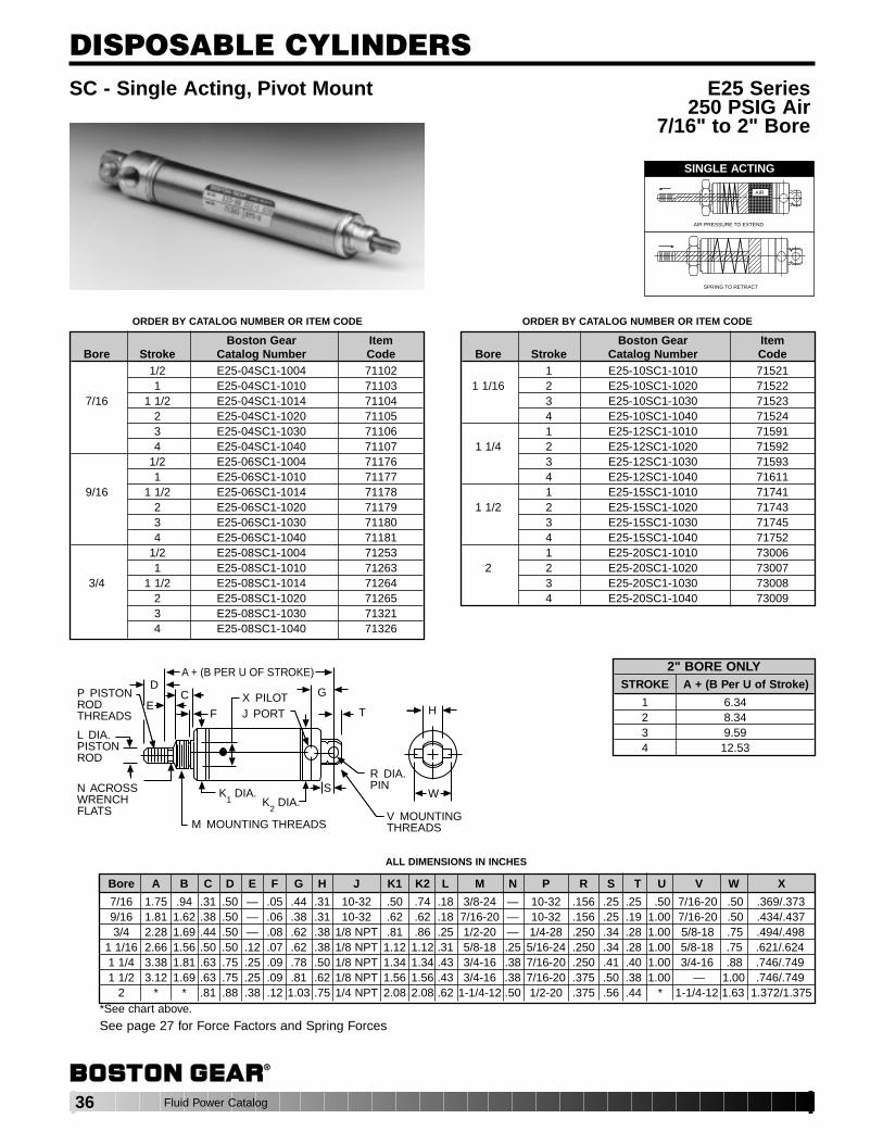
36 Fluid Power Catalog
DISPOSABLE CYLINDERS
2" BORE ONLYSTROKE A + (B Per U of Stroke)
1 6.342 8.343 9.594 12.53
SC - Single Acting, Pivot Mount E25 Series250 PSIG Air
7/16" to 2" Bore
Bore A B C D E F G H J K1 K2 L M N P R S T U V W X
7/16 1.75 .94 .31 .50 — .05 .44 .31 10-32 .50 .74 .18 3/8-24 — 10-32 .156 .25 .25 .50 7/16-20 .50 .369/.3739/16 1.81 1.62 .38 .50 — .06 .38 .31 10-32 .62 .62 .18 7/16-20 — 10-32 .156 .25 .19 1.00 7/16-20 .50 .434/.4373/4 2.28 1.69 .44 .50 — .08 .62 .38 1/8 NPT .81 .86 .25 1/2-20 — 1/4-28 .250 .34 .28 1.00 5/8-18 .75 .494/.498
1 1/16 2.66 1.56 .50 .50 .12 .07 .62 .38 1/8 NPT 1.12 1.12 .31 5/8-18 .25 5/16-24 .250 .34 .28 1.00 5/8-18 .75 .621/.6241 1/4 3.38 1.81 .63 .75 .25 .09 .78 .50 1/8 NPT 1.34 1.34 .43 3/4-16 .38 7/16-20 .250 .41 .40 1.00 3/4-16 .88 .746/.7491 1/2 3.12 1.69 .63 .75 .25 .09 .81 .62 1/8 NPT 1.56 1.56 .43 3/4-16 .38 7/16-20 .375 .50 .38 1.00 — 1.00 .746/.749
2 * * .81 .88 .38 .12 1.03 .75 1/4 NPT 2.08 2.08 .62 1-1/4-12 .50 1/2-20 .375 .56 .44 * 1-1/4-12 1.63 1.372/1.375
SINGLE ACTING
AIR
AIR PRESSURE TO EXTEND
SPRING TO RETRACT
P PISTONRODTHREADS
L DIA.PISTONROD
N ACROSSWRENCHFLATS
E
DA + (B PER U OF STROKE)
X PILOTJ PORT
G
T
R DIA.PIN
V MOUNTINGTHREADS
SK1 DIA.
K2 DIA.
M MOUNTING THREADS
C
F H
W
ORDER BY CATALOG NUMBER OR ITEM CODE ORDER BY CATALOG NUMBER OR ITEM CODE
Boston Gear ItemBore Stroke Catalog Number Code
1/2 E25-04SC1-1004 711021 E25-04SC1-1010 71103
7/16 1 1/2 E25-04SC1-1014 711042 E25-04SC1-1020 711053 E25-04SC1-1030 711064 E25-04SC1-1040 71107
1/2 E25-06SC1-1004 711761 E25-06SC1-1010 71177
9/16 1 1/2 E25-06SC1-1014 711782 E25-06SC1-1020 711793 E25-06SC1-1030 711804 E25-06SC1-1040 71181
1/2 E25-08SC1-1004 712531 E25-08SC1-1010 71263
3/4 1 1/2 E25-08SC1-1014 712642 E25-08SC1-1020 712653 E25-08SC1-1030 713214 E25-08SC1-1040 71326
Boston Gear ItemBore Stroke Catalog Number Code
1 E25-10SC1-1010 715211 1/16 2 E25-10SC1-1020 71522
3 E25-10SC1-1030 715234 E25-10SC1-1040 715241 E25-12SC1-1010 71591
1 1/4 2 E25-12SC1-1020 715923 E25-12SC1-1030 715934 E25-12SC1-1040 716111 E25-15SC1-1010 71741
1 1/2 2 E25-15SC1-1020 717433 E25-15SC1-1030 717454 E25-15SC1-1040 717521 E25-20SC1-1010 73006
2 2 E25-20SC1-1020 730073 E25-20SC1-1030 730084 E25-20SC1-1040 73009
See page 27 for Force Factors and Spring Forces
ALL DIMENSIONS IN INCHES
*See chart above.
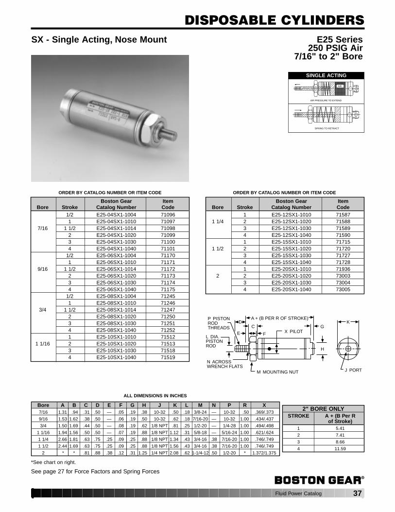
Fluid Power Catalog 37
DISPOSABLE CYLINDERS
2" BORE ONLYSTROKE A + (B Per R
of Stroke)1 5.41
2 7.41
3 8.66
4 11.59
ORDER BY CATALOG NUMBER OR ITEM CODE ORDER BY CATALOG NUMBER OR ITEM CODE
Bore A B C D E F G H J K L M N P R X7/16 1.31 .94 .31 .50 — .05 .19 .38 10-32 .50 .18 3/8-24 — 10-32 .50 .369/.373
9/16 1.53 1.62 .38 .50 — .06 .19 .50 10-32 .62 .18 7/16-20 — 10-32 1.00 .434/.437
3/4 1.50 1.69 .44 .50 — .08 .19 .62 1/8 NPT .81 .25 1/2-20 — 1/4-28 1.00 .494/.498
1 1/16 1.94 1.56 .50 .50 — .07 .19 .88 1/8 NPT 1.12 .31 5/8-18 — 5/16-24 1.00 .621/.624
1 1/4 2.66 1.81 .63 .75 .25 .09 .25 .88 1/8 NPT 1.34 .43 3/4-16 .38 7/16-20 1.00 .746/.749
1 1/2 2.44 1.69 .63 .75 .25 .09 .25 .88 1/8 NPT 1.56 .43 3/4-16 .38 7/16-20 1.00 .746/.749
2 * * .81 .88 .38 .12 .31 1.25 1/4 NPT 2.08 .62 1-1/4-12 .50 1/2-20 * 1.372/1.375
SX - Single Acting, Nose Mount E25 Series250 PSIG Air
7/16" to 2" Bore
M MOUNTING NUT
N ACROSSWRENCH FLATS
L DIA.PISTONROD
P PISTONRODTHREADS
D
E
C
F
A + (B PER R OF STROKE)
X PILOTG
H
K
J PORT
SINGLE ACTING
AIR
AIR PRESSURE TO EXTEND
SPRING TO RETRACT
Boston Gear ItemBore Stroke Catalog Number Code
1/2 E25-04SX1-1004 710961 E25-04SX1-1010 71097
7/16 1 1/2 E25-04SX1-1014 710982 E25-04SX1-1020 710993 E25-04SX1-1030 711004 E25-04SX1-1040 71101
1/2 E25-06SX1-1004 711701 E25-06SX1-1010 71171
9/16 1 1/2 E25-06SX1-1014 711722 E25-06SX1-1020 711733 E25-06SX1-1030 711744 E25-06SX1-1040 71175
1/2 E25-08SX1-1004 712451 E25-08SX1-1010 71246
3/4 1 1/2 E25-08SX1-1014 712472 E25-08SX1-1020 712503 E25-08SX1-1030 712514 E25-08SX1-1040 712521 E25-10SX1-1010 71512
1 1/16 2 E25-10SX1-1020 715133 E25-10SX1-1030 715184 E25-10SX1-1040 71519
Boston Gear ItemBore Stroke Catalog Number Code
1 E25-12SX1-1010 715871 1/4 2 E25-12SX1-1020 71588
3 E25-12SX1-1030 715894 E25-12SX1-1040 715901 E25-15SX1-1010 71715
1 1/2 2 E25-15SX1-1020 717203 E25-15SX1-1030 717274 E25-15SX1-1040 717281 E25-20SX1-1010 71936
2 2 E25-20SX1-1020 730033 E25-20SX1-1030 730044 E25-20SX1-1040 73005
*See chart on right.
See page 27 for Force Factors and Spring Forces
ALL DIMENSIONS IN INCHES

38 Fluid Power Catalog
❏ = manufacturer's stroke length designationMANUFACTURER
BOSTON GEAR C&C Bimba Clippard American Humphrey ParkerBore CYLINDER MODEL AND MOUNTING STYLE Catalog No. Model No. Model No. Model No. Model No. Model No. Model No.
- Nose E25-04SX1-1❏❏❏ RLA❏❏❏-SAN-AA00 01❏ 437SNS-❏ .44NSR❏
Single Acting - Pivot E25-04SC1-1❏❏❏ RLA❏❏❏-SAP-AA00 01❏ -P 437SVS-❏ .44PSR❏
Single Acting Non-Rotating - Nose E25-04NX1-1❏❏❏ RLA❏❏❏-NRN-AA00 01❏ -NR 437SNHS-❏ .44NRSR❏
- Pivot E25-04NC1-1❏❏❏ RLA❏❏❏-NRP-AA00 01❏ -NRP 437RVHS-❏ .44NRPSR❏
Reverse Single Acting - Nose E25-04PX1-1❏❏❏ RLA❏❏❏-RAN-AA00 01❏ -R 437RNS-❏ .44RSR❏
7/16" - Pivot E25-04PC1-1❏❏❏ RLA❏❏❏-RAP-AA00 01❏ -RP 437RVS-❏ .44RPSR❏
- Nose E25-04DX1-1❏❏❏ RLA❏❏❏-DAN-AA00 01❏ -D 437DNS-❏ .44DSR❏
Double Acting - Pivot E25-04DC1-1❏❏❏ RLA❏❏❏-DAP-AA00 01❏ -DP 437DVS-❏ .44DPSR❏
- Double End E25-04DS1-1❏❏❏ RLA❏❏❏-DAD-AA00 01❏ -DX 437DVS-❏ -2 .44DXPSR❏
Double Acting Double Rod End - Double End E25-04DR1-1❏❏❏ RLA❏❏❏-DRD-AA00 01❏ -DXDE 437DES-❏ .44KDXSR❏
Single Acting - Nose E25-06SX1-1❏❏❏ RLB❏❏❏-SAN-AA00 02❏ 562SNS-❏ .56NSR❏
- Pivot E25-06SC1-1❏❏❏ RLB❏❏❏-SAP-AA00 02❏ -P 562SVS-❏ .56PSR❏
Single Acting Non-Rotating - Nose E25-06NX1-1❏❏❏ RLB❏❏❏-NRN-AA00 02❏ -NR 562SNHS-❏ .56NRSR❏
- Pivot E25-06NC1-1❏❏❏ RLB❏❏❏-NRP-AA00 02❏ -NRP 562SVHS-❏ .56NRPSR❏
Reverse Single Acting - Nose E25-06PX1-1❏❏❏ RLB❏❏❏-RAN-AA00 02❏ -R 562RNS-❏ .56RSR❏
9/16" - Pivot E25-06PC1-1❏❏❏ RLB❏❏❏-RAP-AA00 02❏ -RP 562RVS-❏ .56RPSR❏
- Nose E25-06DX1-1❏❏❏ RLB❏❏❏-DAN-AA00 02❏ -D 562DNS-❏ .56DSR❏
Double Acting - Pivot E25-06DC1-1❏❏❏ RLB❏❏❏-DAP-AA00 02❏ -DXP 562DVS-❏ .56DXPSR❏
- Double End E25-06DS1-1❏❏❏ RLB❏❏❏-DAD-AA00 02❏ -DXP 562DVS-❏ -2 .56DXPSR❏
Double Acting Double Rod End - Double End E25-06DR1-1❏❏❏ RLB❏❏❏-DRD-AA00 02❏ -DXDE 562DES-❏ .56KDXSR❏
- Nose E25-08SX1-1❏❏❏ RLC❏❏❏-SAN-AA00 04❏ SSR-12-❏ 750SNS-❏ 7-S-❏ .75NSR❏
Single Acting - Pivot E25-08SC1-1❏❏❏ RLC❏❏❏-SAP-AA00 04❏ -P USR-12-❏ 750SVS-❏ 7-SP-❏ .75PSR❏
Single Acting Non-Rotating - Nose E25-08NX1-1❏❏❏ RLC❏❏❏-NRN-AA00 04❏ -NR SSN-12-❏ 750SNHS-❏ 7-SH-❏ .75NRSR❏
- Pivot E25-08NC1-1❏❏❏ RLC❏❏❏-NRP-AA00 04❏ -NRP USN-12-❏ 750SVHS-❏ 7-SHP-❏ .75NRPSR❏
Reverse Single Acting - Nose E25-08PX1-1❏❏❏ RLC❏❏❏-RAN-AA00 04❏ -R SSR-12-❏ 750RNS-❏ 7-SR-❏ .75RSR❏
3/4" - Pivot E25-08PC1-1❏❏❏ RLC❏❏❏-RAP-AA00 04❏ -RP URR-12-❏ 750RVS-❏ 7-SRP-❏ .75RPSR❏
- Nose E25-08DX1-1❏❏❏ RLC❏❏❏-DAN-AA00 04❏ -D SDR-12-❏ 750DNS-❏ 7-D-❏ .75DSR❏
Double Acting - Pivot E25-08DC1-1❏❏❏ RLC❏❏❏-DAP-AA00 04❏ -DP UDR-12-❏ 750DVS-❏ 7-DP-❏ .75DPSR❏
- Double End E25-08DS1-1❏❏❏ RLC❏❏❏-DAD-AA00 04❏ -DX UDR-12-❏ 750DVS-❏ -2 7-DP-❏ .75DXPSR❏
Double Acting Double Rod End - Double End E25-08DR1-1❏❏❏ RLC❏❏❏-DRD-AA00 04❏ -DXDE SDD-12-❏ 750DES-❏ 7-D2EY-❏ .75KDXSR❏
DISPOSABLE CYLINDERS
N/A N/A
Competitive Cross-Reference Guide
Boston Gear’s E25 Series of disposable cylinders are designed to be functionally and dimensionally interchangeable with theseand many other manufacturers cylinders. This chart is intended to be a guide only. Please see the appropriate manufacturer’scatalogs for exact details regarding specifications and dimensions.

Fluid Power Catalog 39
DISPOSABLE CYLINDERS
❏ = manufacturer's stroke length designationMANUFACTURER
BOSTON GEAR C&C Bimba Clippard American Humphrey ParkerBore CYLINDER MODEL AND MOUNTING STYLE Catalog No. Model No. Model No. Model No. Model No. Model No. Model No.
- Nose E25-10SX1-1❏❏❏ RLD❏❏❏-SAN-AA00 09❏ SSR-17-❏ 1062SNS-❏ 6-S-❏ 1.06NSR❏
Single Acting - Pivot E25-10SC1-1❏❏❏ RLD❏❏❏-SAP-AA00 09❏ -P USR-17-❏ 1062SVS-❏ 6-SP-❏ 1.06PSR❏
Single Acting Non-Rotating - Nose E25-10NX1-1❏❏❏ RLD❏❏❏-NRN-AA00 09❏ -NR SSN-17-❏ 1062SNHS-❏ 6-SH-❏ 1.06NRSR❏
- Pivot E25-10NC1-1❏❏❏ RLD❏❏❏-NRP-AA00 09❏ -NRP USN-17-❏ 1062SVHS-❏ 6-SHP-❏ 1.06NRPSR❏
Reverse Single Acting - Nose E25-10PX1-1❏❏❏ RLD❏❏❏-RAN-AA00 09❏ -R SSR-17-❏ 1062RNS-❏ 6-SR-❏ 1.06RSR❏
1 1/16" - Pivot E25-10PC1-1❏❏❏ RLD❏❏❏-RAP-AA00 09❏ -RP URR-17-❏ 1062RVS-❏ 6-SRP-❏ 1.06RPSR❏
- Nose E25-10DX1-1❏❏❏ RLD❏❏❏-DAN-AA00 09❏ -D SDR-17-❏ 1062DNS-❏ 6-D-❏ 1.06DSR❏
Double Acting - Pivot E25-10DC1-1❏❏❏ RLD❏❏❏-DAP-AA00 09❏ -DP UDR-17-❏ 1062DVS-❏ 6-DP-❏ 1.06DPSR❏
- Double End E25-10DS1-1❏❏❏ RLD❏❏❏-DAD-AA00 09❏ -DX UDR-17-❏ 1062DVS-❏ -2 6-DP-❏ 1.06DXPSR❏
Double Acting Double Rod End - Double End E25-10DR1-1❏❏❏ RLD❏❏❏-DRD-AA00 09❏ -DXDE SDD-17-❏ 1062DES-❏ 6-D2EY-❏ 1.06KDXSR❏
Single Acting - Nose E25-12SX1-1❏❏❏ RLE❏❏❏-SAN-AA00 12❏ SSR-20-❏ 1250SNS-❏ 25-S-❏ 1.25NSR❏
- Pivot E25-12SC1-1❏❏❏ RLE❏❏❏-SAP-AA00 12❏ -P USR-20-❏ 1250SVS-❏ 25-SP-❏ 1.25PSR❏
Single Acting Non-Rotating - Nose E25-12NX1-1❏❏❏ RLE❏❏❏-NRN-AA00 12❏ -NR SSN-20-❏ 1250SNHS-❏ 25-SH-❏ 1.25NRSR❏
- Pivot E25-12NC1-1❏❏❏ RLE❏❏❏-NRP-AA00 12❏ -NRP USN-20-❏ 1250SVHS-❏ 25-SHP-❏ 1.25NRPSR❏
Reverse Single Acting - Nose E25-12PX1-1❏❏❏ RLE❏❏❏-RAN-AA00 12❏ -R SRR-20-❏ 1250RNS-❏ 25-SR-❏ 1.25RSR❏
1 1/4" - Pivot E25-12PC1-1❏❏❏ RLE❏❏❏-RAP-AA00 12❏ -RP URR-20-❏ 1250RVS-❏ 25-SRP-❏ 1.25RPSR❏
- Nose E25-12DX1-1❏❏❏ RLE❏❏❏-DAN-AA00 12❏ -D SDR-20-❏ 1250DNS-❏ 25-D-❏ 1.25DSR❏
Double Acting - Pivot E25-12DC1-1❏❏❏ RLE❏❏❏-DAP-AA00 12❏ -DP UDR-20-❏ 1250DVS-❏ 25-DP-❏ 1.25DXPSR❏
- Double End E25-12DS1-1❏❏❏ RLE❏❏❏-DAD-AA00 12❏ -DP UDR-20-❏ 1250DVS-❏ -2 25-DP-❏ 1.25DXPSR❏
Double Acting Double Rod End - Double End E25-12DR1-1❏❏❏ RLE❏❏❏-DRD-AA00 12❏ -DXDE SDD-20-❏ 1250DES-❏ 25-D2EY-❏ 1.25KDXSR❏
- Nose E25-15SX1-1❏❏❏ RLF❏❏❏-SAN-AA00 17❏ SSR-24-❏ 1500SNS-❏ 5-S-❏ 1.50NSR❏
Single Acting - Pivot E25-15SC1-1❏❏❏ RLF❏❏❏-SAP-AA00 17❏ -P CSR-24-❏ 1500SVS-❏ 5-SP-❏ 1.50PSR❏
Single Acting Non-Rotating - Nose E25-15NX1-1❏❏❏ RLF❏❏❏-NRN-AA00 17❏ -NR SSN-24-❏ 1500SNHS-❏ 5-SH-❏ 1.50NRSR❏
- Pivot E25-15NC1-1❏❏❏ RLF❏❏❏-NRP-AA00 17❏ -NRP CSN-24-❏ 1500SVHS-❏ 5-SHP-❏ 1.50NRPSR❏
Reverse Single Acting - Nose E25-15PX1-1❏❏❏ RLF❏❏❏-RAN-AA00 17❏ -R SRR-24-❏ 1500RNS-❏ 5-SR-❏ 1.50RSR❏
1 1/2" - Pivot E25-15PC1-1❏❏❏ RLF❏❏❏-RAP-AA00 17❏ -RP CRR-24-❏ 1500RVS-❏ 5-SRP-❏ 1.50RPSR❏
- Nose E25-15DX1-1❏❏❏ RLF❏❏❏-DAN-AA00 17❏ -D SDR-24-❏ 1500DNS-❏ 5-D-❏ 1.50DSR❏
Double Acting - Pivot E25-15DC1-1❏❏❏ RLF❏❏❏-DAP-AA00 17❏ -DP CDR-24-❏ 1500DVS-❏ 5-DP-❏ 1.50DPSR❏
- Double End E25-15DS1-1❏❏❏ RLF❏❏❏-DAD-AA00 17❏ -DX EDR-24-❏ 1500DVS-❏ -2 5-DP-❏ 1.50DXSR❏
Double Acting Double Rod End - Double End E25-15DR1-1❏❏❏ RLF❏❏❏-DRD-AA00 17❏ -DXDE SDD-24-❏ 1500DES-❏ 5-D2EY-❏ 1.50KDXSR❏
Single Acting - Nose E25-20SX1-1❏❏❏ RLG❏❏❏-SAN-AA00 31❏ 4-S-❏ 2.00NSR❏
- Pivot E25-20SC1-1❏❏❏ RLG❏❏❏-SAP-AA00 31❏ -XP 4-SP-❏ 2.00PSR❏
Reverse Single Acting - Nose E25-20PX1-1❏❏❏ RLG❏❏❏-RAN-AA00 31❏ -R 4-SR-❏ 2.00RSR❏
2" - Pivot E25-20PC1-1❏❏❏ RLG❏❏❏-RAP-AA00 31❏ -RP 4-SRP-❏ 2.00RPSR❏
- Nose E25-20DX1-1❏❏❏ RLG❏❏❏-DAN-AA00 31❏ -D SDR-32-❏ 4-D-❏ 2.00DSR❏
Double Acting - Pivot E25-20DC1-1❏❏❏ RLG❏❏❏-DAP-AA00 31❏ -DXP UDR-32-❏ 4-DP-❏ 2.00DXPSR❏
- Double End E25-20DS1-1❏❏❏ RLG❏❏❏-DAD-AA00 31❏ -DXP UDR-32-❏ 4-DP-❏ 2.00DXPSR❏
Double Acting Double Rod End - Double End E25-20DR1-1❏❏❏ RLG❏❏❏-DRD-AA00 31❏ -DXDE N/A 2000DES-❏ 4-D2EY-❏ 2.00KDXSR❏
- Nose E25-25DX1-1❏❏❏ RLH❏❏❏-DAN-AA00 50❏ -D N/A 3-D-❏Double Acting - Pivot E25-25DC1-1❏❏❏ RLH❏❏❏-DAP-AA00 50❏ -DXP UDR-40-❏ 3-DP-❏
2 1/2" - Double End E25-25DS1-1❏❏❏ RLH❏❏❏-DAD-AA00 50❏ -DXP UDR-40-❏ 3-DP-❏Double Acting Double Rod End - Double End E25-25DR1-1❏❏❏ RLH❏❏❏-DRD-AA00 50❏ -DXDE N/A 3-D2EY-❏
N/A
N/A
N/A N/A
Competitive Cross-Reference Guide
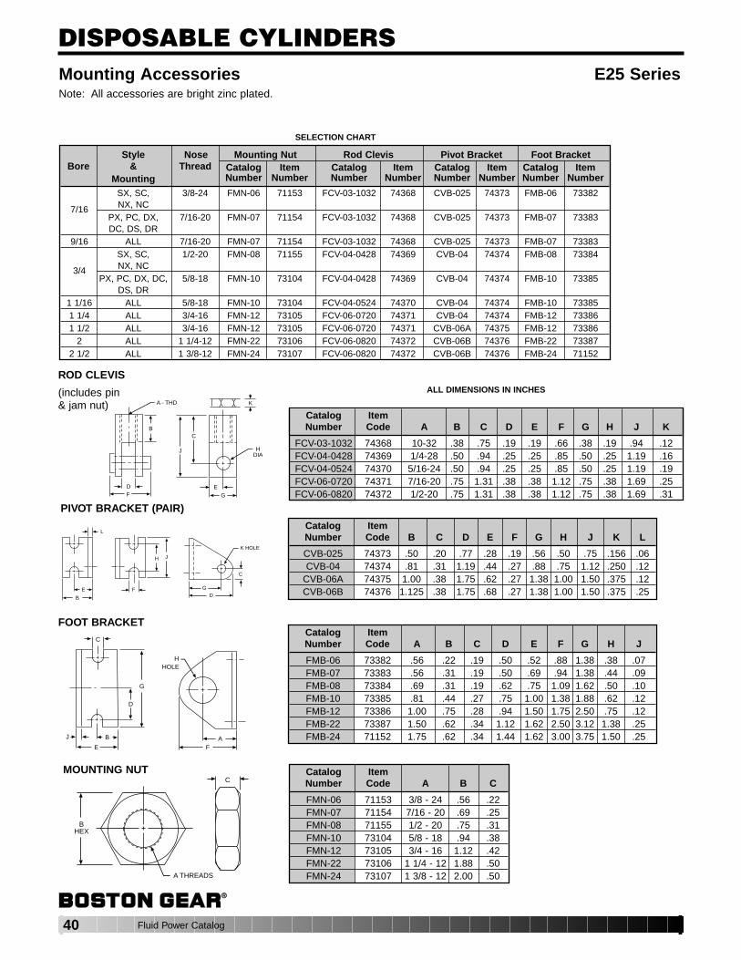
40 Fluid Power Catalog
DISPOSABLE CYLINDERSMounting Accessories E25 SeriesNote: All accessories are bright zinc plated.
ALL DIMENSIONS IN INCHES
Catalog ItemNumber Code A B C D E F G H J K
FCV-03-1032 74368 10-32 .38 .75 .19 .19 .66 .38 .19 .94 .12FCV-04-0428 74369 1/4-28 .50 .94 .25 .25 .85 .50 .25 1.19 .16FCV-04-0524 74370 5/16-24 .50 .94 .25 .25 .85 .50 .25 1.19 .19FCV-06-0720 74371 7/16-20 .75 1.31 .38 .38 1.12 .75 .38 1.69 .25FCV-06-0820 74372 1/2-20 .75 1.31 .38 .38 1.12 .75 .38 1.69 .31
ROD CLEVIS
(includes pin & jam nut)
B
DF
A - THD
HDIA
EG
C
J
K
Catalog ItemNumber Code B C D E F G H J K L
CVB-025 74373 .50 .20 .77 .28 .19 .56 .50 .75 .156 .06CVB-04 74374 .81 .31 1.19 .44 .27 .88 .75 1.12 .250 .12
CVB-06A 74375 1.00 .38 1.75 .62 .27 1.38 1.00 1.50 .375 .12CVB-06B 74376 1.125 .38 1.75 .68 .27 1.38 1.00 1.50 .375 .25
PIVOT BRACKET (PAIR)
K HOLE
C
GD
F
H J
E
B
L
Catalog ItemNumber Code A B C D E F G H J
FMB-06 73382 .56 .22 .19 .50 .52 .88 1.38 .38 .07FMB-07 73383 .56 .31 .19 .50 .69 .94 1.38 .44 .09FMB-08 73384 .69 .31 .19 .62 .75 1.09 1.62 .50 .10FMB-10 73385 .81 .44 .27 .75 1.00 1.38 1.88 .62 .12FMB-12 73386 1.00 .75 .28 .94 1.50 1.75 2.50 .75 .12FMB-22 73387 1.50 .62 .34 1.12 1.62 2.50 3.12 1.38 .25FMB-24 71152 1.75 .62 .34 1.44 1.62 3.00 3.75 1.50 .25
FOOT BRACKET
FA
HHOLE
G
D
C
BJ
E
Catalog ItemNumber Code A B C
FMN-06 71153 3/8 - 24 .56 .22FMN-07 71154 7/16 - 20 .69 .25FMN-08 71155 1/2 - 20 .75 .31FMN-10 73104 5/8 - 18 .94 .38FMN-12 73105 3/4 - 16 1.12 .42FMN-22 73106 1 1/4 - 12 1.88 .50FMN-24 73107 1 3/8 - 12 2.00 .50
MOUNTING NUTC
BHEX
A THREADS
Style Nose Mounting Nut Rod Clevis Pivot Bracket Foot BracketBore & Thread Catalog Item Catalog Item Catalog Item Catalog Item
Mounting Number Number Number Number Number Number Number Number
SX, SC, 3/8-24 FMN-06 71153 FCV-03-1032 74368 CVB-025 74373 FMB-06 73382
7/16 NX, NCPX, PC, DX, 7/16-20 FMN-07 71154 FCV-03-1032 74368 CVB-025 74373 FMB-07 73383DC, DS, DR
9/16 ALL 7/16-20 FMN-07 71154 FCV-03-1032 74368 CVB-025 74373 FMB-07 73383SX, SC, 1/2-20 FMN-08 71155 FCV-04-0428 74369 CVB-04 74374 FMB-08 73384
3/4 NX, NCPX, PC, DX, DC, 5/8-18 FMN-10 73104 FCV-04-0428 74369 CVB-04 74374 FMB-10 73385
DS, DR1 1/16 ALL 5/8-18 FMN-10 73104 FCV-04-0524 74370 CVB-04 74374 FMB-10 733851 1/4 ALL 3/4-16 FMN-12 73105 FCV-06-0720 74371 CVB-04 74374 FMB-12 733861 1/2 ALL 3/4-16 FMN-12 73105 FCV-06-0720 74371 CVB-06A 74375 FMB-12 73386
2 ALL 1 1/4-12 FMN-22 73106 FCV-06-0820 74372 CVB-06B 74376 FMB-22 733872 1/2 ALL 1 3/8-12 FMN-24 73107 FCV-06-0820 74372 CVB-06B 74376 FMB-24 71152
SELECTION CHART
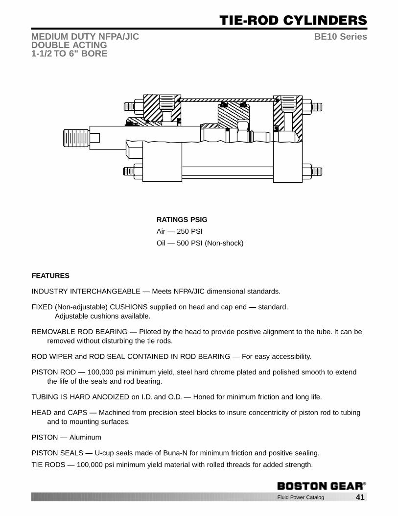
Fluid Power Catalog 41
TIE-ROD CYLINDERS
RATINGS PSIG
Air — 250 PSI
Oil — 500 PSI (Non-shock)
FEATURES
INDUSTRY INTERCHANGEABLE — Meets NFPA/JIC dimensional standards.
FIXED (Non-adjustable) CUSHIONS supplied on head and cap end — standard.Adjustable cushions available.
REMOVABLE ROD BEARING — Piloted by the head to provide positive alignment to the tube. It can beremoved without disturbing the tie rods.
ROD WIPER and ROD SEAL CONTAINED IN ROD BEARING — For easy accessibility.
PISTON ROD — 100,000 psi minimum yield, steel hard chrome plated and polished smooth to extendthe life of the seals and rod bearing.
TUBING IS HARD ANODIZED on I.D. and O.D. — Honed for minimum friction and long life.
HEAD and CAPS — Machined from precision steel blocks to insure concentricity of piston rod to tubingand to mounting surfaces.
PISTON — Aluminum
PISTON SEALS — U-cup seals made of Buna-N for minimum friction and positive sealing.
TIE RODS — 100,000 psi minimum yield material with rolled threads for added strength.
MEDIUM DUTY NFPA/JIC BE10 SeriesDOUBLE ACTING1-1/2 TO 6" BORE

42 Fluid Power Catalog
TIE-ROD CYLINDERS
HOW TO ORDER BE10 SERIES CYLINDERS
To develop a Cylinder Order Number, select only those CodeNumbers that represent the cylinder required, and place in thesequence shown below:
EXAMPLE: Required Cylinder — Medium Duty Air Cylinder, 4" Bore, Detachable Clevis (NFPA Mounting—MP2), Standard Rod,Adjustable Cushion Head End, Standard Port location, 73" of Stroke, 1" Standard Rod Diameter, 1-14 Full DiameterRod Threads.
SPECIFYBE10 40 P2 2 1 73 0 02
DOUBLE ACTING BE10 Series
ROD DIAMETERS AVAILABLERod Bore Dia.Dia. 1-1/2 2 2-1/2 3-1/4 4 5 6
5/8 STD STD STD — — — —1 1st OS† 1st OS 1st OS STD STD STD —
1-3/8 — A A 1st OS 1st OS 1st OS STD1-3/4 — — A A A A 1st OS
2 — — — A A A A2-1/2 — — — — A A A
3 — — — — — A A3-1/2 — — — — — A A
4 — — — — — — A
STD — Standard Rod Diameter; 1st OS — First Oversized Rod DiameterA — Available Rod Diameters, Consult Factory† — Adjustable cushion not available on head end, 1-1/2" bore with 1" rod diameter.
Series
BE10Pneumatic
Code BoreNo. DIa.
15 - 1-1/220 - 225 - 2-1/232 - 3-1/440 - 450 - 560 - 6
Code NFPANo. Mounting Des.
BX - None (Basic Cylinder) —DBX - Double Rod Basic —F1 - Head Rectangular Flange MF1F2 - Cap Rectangular Flange MF2F5 - Head Square Flange MF5F6 - Cap Square Flange MF6P1 - Cap Fixed Clevis MP1P2 - Cap Detachable Clevis MP2P3 - Cap Fixed Eye MP3S2 - Side Lugs MS2S4 - Side Tapped MS4S7 - Side End Lugs MS7T1 - Head Trunnion MT1T2 - Cap Trunnion MT2T4 - Intermediate Trunnion MT4X1 - Extended Tie Rods-Both Ends MX1X2 - Extended Tie Rods-Cap End MX2X3 - Extended Tie Rods-Head End MX3
Code CushionsNo. and Rod
Standard Rod Diameter1 - Non-Adjustable
Cushions2 - Cushioned
Head End3 - Cushioned
Cap End4 - Cushioned
Both Ends1st Oversize
Rod Diameter5 - Non-Adjustable
Cushions6 - Cushioned
Head End7 - Cushioned
Cap End8 - Cushioned
Both Ends9 - 2nd Oversize
Rods andlarger-Specify
Code PortNo. Positions**
1 - StandardPort Position
2 - 90° ClockwisePort Position
3 - 180° ClockwisePort Position
4 - 270° ClockwisePort Position
Stroke inCode WholeNo. Inches
01 - 1 inch05 - 512 -1225 - 2530 - 3043 - 4366 - 66
etc.
FractionalCode StrokeNo. Length
0 - No fraction1 - 1/8 inch2 - 1/43 - 3/84 - 1/25 - 5/86 - 3/47 - 7/89 - For
fractionsnot shown- Specify
Code ModificationNo. Descriptions
- Style 1StandardThread (codenot required —leave blank)
02 - Style 2 RodEnd — Fulldiameter Male Th’d.
03 - Style 3 RodEnd — Female Th’d.
04 - Style 4 RodEnd —OptionalShoulder, Male Th’d.
XX - Special(Specify)
Add D to mounting for Double Rod ex. DS4 **View facing Rod End.
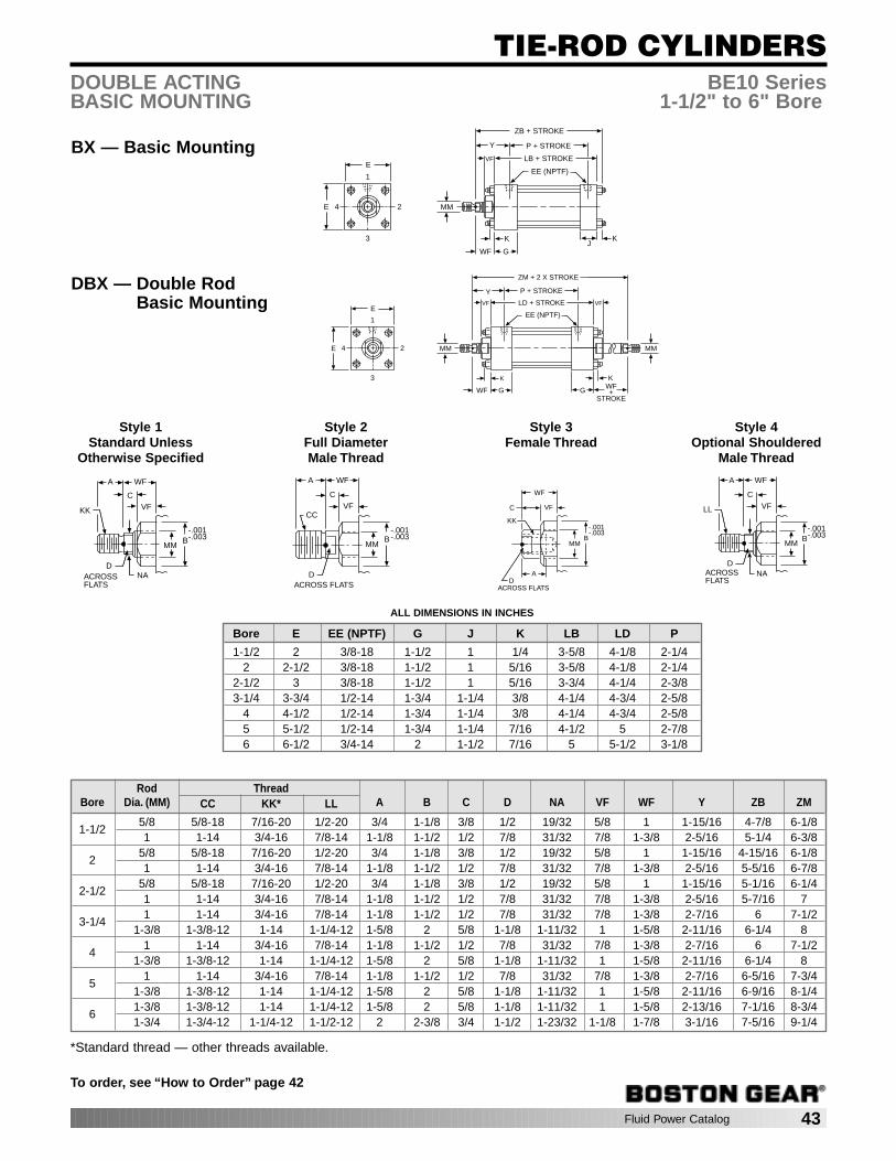
Fluid Power Catalog 43
TIE-ROD CYLINDERS
To order, see “How to Order” page 42
BX — Basic Mounting
DOUBLE ACTING BE10 SeriesBASIC MOUNTING 1-1/2" to 6" Bore
K
E 2
3J
G
K
Y
MM
EE (NPTF)1
4
E
P + STROKE
ZB + STROKE
LB + STROKEVF
WF
DBX — Double RodBasic Mounting
K
E 2
3
G
K
Y
MM
EE (NPTF)1
4
E
P + STROKE
ZM + 2 X STROKE
LD + STROKEVF
WF
MM
GWF+
STROKE
VF
Style 1Standard Unless
Otherwise Specified
Style 2Full Diameter Male Thread
Style 3Female Thread
Style 4Optional Shouldered
Male Thread
WFA
KK
CVF
D
MM
NA
B-.001-.003
ACROSSFLATS
WFA
CC
CVF
D
MMB
-.001-.003
ACROSS FLATS
WF
KK
C VF
D
MMB
-.001-.003
ACROSS FLATS
A
WFA
LL
C
VF
D
MM
NA
B-.001-.003
ACROSSFLATS
ALL DIMENSIONS IN INCHES
Bore E EE (NPTF) G J K LB LD P
1-1/2 2 3/8-18 1-1/2 1 1/4 3-5/8 4-1/8 2-1/42 2-1/2 3/8-18 1-1/2 1 5/16 3-5/8 4-1/8 2-1/4
2-1/2 3 3/8-18 1-1/2 1 5/16 3-3/4 4-1/4 2-3/83-1/4 3-3/4 1/2-14 1-3/4 1-1/4 3/8 4-1/4 4-3/4 2-5/8
4 4-1/2 1/2-14 1-3/4 1-1/4 3/8 4-1/4 4-3/4 2-5/85 5-1/2 1/2-14 1-3/4 1-1/4 7/16 4-1/2 5 2-7/86 6-1/2 3/4-14 2 1-1/2 7/16 5 5-1/2 3-1/8
Rod ThreadBore Dia. (MM) CC KK* LL A B C D NA VF WF Y ZB ZM
1-1/25/8 5/8-18 7/16-20 1/2-20 3/4 1-1/8 3/8 1/2 19/32 5/8 1 1-15/16 4-7/8 6-1/81 1-14 3/4-16 7/8-14 1-1/8 1-1/2 1/2 7/8 31/32 7/8 1-3/8 2-5/16 5-1/4 6-3/8
25/8 5/8-18 7/16-20 1/2-20 3/4 1-1/8 3/8 1/2 19/32 5/8 1 1-15/16 4-15/16 6-1/81 1-14 3/4-16 7/8-14 1-1/8 1-1/2 1/2 7/8 31/32 7/8 1-3/8 2-5/16 5-5/16 6-7/8
2-1/25/8 5/8-18 7/16-20 1/2-20 3/4 1-1/8 3/8 1/2 19/32 5/8 1 1-15/16 5-1/16 6-1/41 1-14 3/4-16 7/8-14 1-1/8 1-1/2 1/2 7/8 31/32 7/8 1-3/8 2-5/16 5-7/16 7
3-1/41 1-14 3/4-16 7/8-14 1-1/8 1-1/2 1/2 7/8 31/32 7/8 1-3/8 2-7/16 6 7-1/2
1-3/8 1-3/8-12 1-14 1-1/4-12 1-5/8 2 5/8 1-1/8 1-11/32 1 1-5/8 2-11/16 6-1/4 8
41 1-14 3/4-16 7/8-14 1-1/8 1-1/2 1/2 7/8 31/32 7/8 1-3/8 2-7/16 6 7-1/2
1-3/8 1-3/8-12 1-14 1-1/4-12 1-5/8 2 5/8 1-1/8 1-11/32 1 1-5/8 2-11/16 6-1/4 8
51 1-14 3/4-16 7/8-14 1-1/8 1-1/2 1/2 7/8 31/32 7/8 1-3/8 2-7/16 6-5/16 7-3/4
1-3/8 1-3/8-12 1-14 1-1/4-12 1-5/8 2 5/8 1-1/8 1-11/32 1 1-5/8 2-11/16 6-9/16 8-1/4
61-3/8 1-3/8-12 1-14 1-1/4-12 1-5/8 2 5/8 1-1/8 1-11/32 1 1-5/8 2-13/16 7-1/16 8-3/41-3/4 1-3/4-12 1-1/4-12 1-1/2-12 2 2-3/8 3/4 1-1/2 1-23/32 1-1/8 1-7/8 3-1/16 7-5/16 9-1/4
*Standard thread — other threads available.
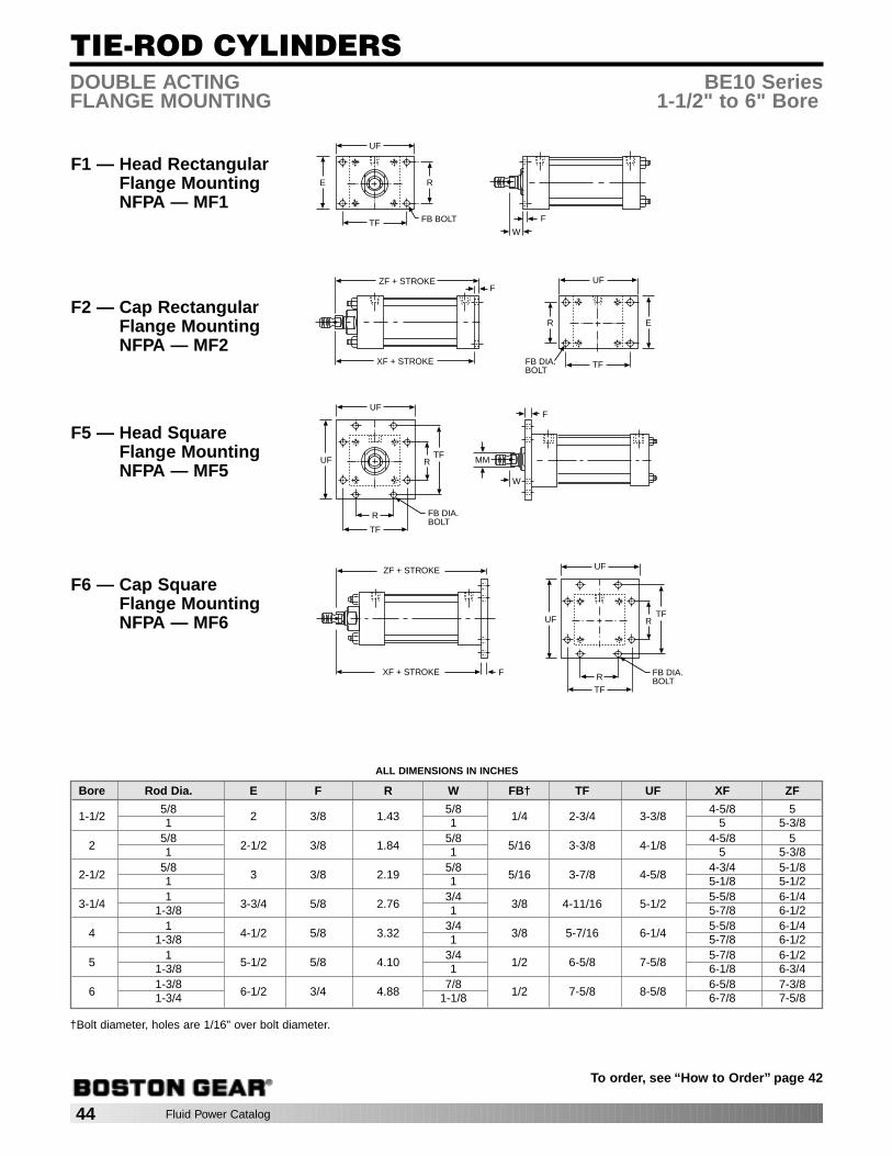
44 Fluid Power Catalog
TIE-ROD CYLINDERS
To order, see “How to Order” page 42
DOUBLE ACTING BE10 SeriesFLANGE MOUNTING 1-1/2" to 6" Bore
F1 — Head RectangularFlange MountingNFPA — MF1
R
FB BOLT
E
TF
UF
F
W
F2 — Cap RectangularFlange MountingNFPA — MF2
R
FB DIA.BOLT
E
TF
UFZF + STROKE
XF + STROKE
F
F5 — Head SquareFlange MountingNFPA — MF5
R
FB DIA.BOLT
UF
TF
UF
R
TFMM
F
W
F6 — Cap SquareFlange MountingNFPA — MF6 R
FB DIA.BOLT
UF
TF
UF
R
TF
F
ZF + STROKE
XF + STROKE
ALL DIMENSIONS IN INCHES
Bore Rod Dia. E F R W FB† TF UF XF ZF
1-1/25/8
2 3/8 1.435/8
1/4 2-3/4 3-3/84-5/8 5
1 1 5 5-3/8
25/8
2-1/2 3/8 1.845/8
5/16 3-3/8 4-1/84-5/8 5
1 1 5 5-3/8
2-1/25/8
3 3/8 2.195/8
5/16 3-7/8 4-5/84-3/4 5-1/8
1 1 5-1/8 5-1/2
3-1/41
3-3/4 5/8 2.763/4
3/8 4-11/16 5-1/25-5/8 6-1/4
1-3/8 1 5-7/8 6-1/2
41
4-1/2 5/8 3.323/4
3/8 5-7/16 6-1/45-5/8 6-1/4
1-3/8 1 5-7/8 6-1/2
51
5-1/2 5/8 4.103/4
1/2 6-5/8 7-5/85-7/8 6-1/2
1-3/8 1 6-1/8 6-3/4
61-3/8
6-1/2 3/4 4.887/8
1/2 7-5/8 8-5/86-5/8 7-3/8
1-3/4 1-1/8 6-7/8 7-5/8
†Bolt diameter, holes are 1/16" over bolt diameter.

Fluid Power Catalog 45
TIE-ROD CYLINDERS
To order, see “How to Order” page 42
DOUBLE ACTING BE10 SeriesCLEVIS MOUNTING 1-1/2" to 6" Bore
P1 — Cap FixedClevis MountingNFPA — MP1
M
ZC + STROKE
XC + STROKE
E
CB
CW
CD
LR
MR
CWCW
E
L
P2 — Cap DetachableClevis MountingNFPA — MP2
M
ZD + STROKE
XD + STROKE
E
CB
CW
CD
LR
MR
CWCW
E
F
L
P3 — Cap FixedEye MountingNFPA — MP3
M
ZC + STROKE
XC + STROKE
ECD
LR
MRE
L EW
ALL DIMENSIONS IN INCHES
Bore Rod Dia. E F L M CB CD CW EW LR MR XC XD ZC ZD
1-1/25/8
2 3/8 3/4 1/2 3/4 1/2 1/2 3/4 5/8 19/325-3/8 5-3/4 5-7/8 6-1/4
1 5-3/4 6-1/8 6-1/4 6-5/8
25/8
2-1/2 3/8 3/4 1/2 3/4 1/2 1/2 3/4 5/8 19/325-3/8 5-3/4 5-7/8 6-1/4
1 5-3/4 6-1/8 6-1/4 6-5/8
2-1/25/8
3 3/8 3/4 1/2 3/4 1/2 1/2 3/4 5/8 19/325-1/2 5-7/8 6 6-3/8
1 5-7/8 6-1/4 6-3/8 6-3/4
3-1/41
3-3/4 5/8 1-1/4 3/4 1-1/4 3/4 5/8 1-1/4 1 7/86-7/8 7-1/2 7-5/8 8-1/4
1-3/8 7-1/8 7-3/4 7-7/8 8-1/2
41
4-1/2 5/8 1-1/4 3/4 1-1/4 3/4 5/8 1-1/4 1 7/86-7/8 7-1/2 7-5/8 8-1/4
1-3/8 7-1/8 7-3/4 7-7/8 8-1/2
51
5-1/2 5/8 1-1/4 3/4 1-1/4 3/4 5/8 1-1/4 1 7/87-1/8 7-3/4 7-7/8 8-1/2
1-3/8 7-3/8 8 8-1/8 8-3/4
61-3/8
6-1/2 3/4 1-1/2 1 1-1/2 1 3/4 1-1/2 1-1/4 1-7/328-1/8 8-7/8 9-1/8 9-7/8
1-3/4 8-3/8 9-1/8 9-3/8 10-1/8
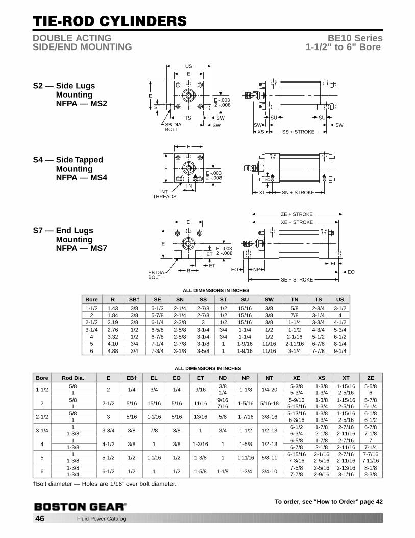
46 Fluid Power Catalog
TIE-ROD CYLINDERS
To order, see “How to Order” page 42
DOUBLE ACTING BE10 SeriesSIDE/END MOUNTING 1-1/2" to 6" Bore
S2 — Side LugsMountingNFPA — MS2
E
E
US
ST
TS SW
SWSB DIA.BOLT
E -.0032 -.008
SS + STROKEXSSW
SU SU
SW
S4 — Side TappedMountingNFPA — MS4
E
E
TNNT
THREADSSN + STROKEXT
ND
E -.0032 -.008
S7 — End LugsMountingNFPA — MS7
SE + STROKE
EO NP
E
E
ET
RET
EB DIA.BOLT
XE + STROKE
EL
EO
E -.0032 -.008
ZE + STROKE
ALL DIMENSIONS IN INCHES
Bore Rod Dia. E EB† EL EO ET ND NP NT XE XS XT ZE
1-1/25/8
2 1/4 3/4 1/4 9/163/8
1-1/8 1/4-205-3/8 1-3/8 1-15/16 5-5/8
1 1/4 5-3/4 1-3/4 2-5/16 6
25/8
2-1/2 5/16 15/16 5/16 11/169/16
1-5/16 5/16-185-9/16 1-3/8 1-15/16 5-7/8
1 7/16 5-15/16 1-3/4 2-5/16 6-1/4
2-1/25/8
3 5/16 1-1/16 5/16 13/16 5/8 1-7/16 3/8-165-13/16 1-3/8 1-15/16 6-1/8
1 6-3/16 1-3/4 2-5/16 6-1/2
3-1/41
3-3/4 3/8 7/8 3/8 1 3/4 1-1/2 1/2-136-1/2 1-7/8 2-7/16 6-7/8
1-3/8 6-3/4 2-1/8 2-11/16 7-1/8
41
4-1/2 3/8 1 3/8 1-3/16 1 1-5/8 1/2-136-5/8 1-7/8 2-7/16 7
1-3/8 6-7/8 2-1/8 2-11/16 7-1/4
51
5-1/2 1/2 1-1/16 1/2 1-3/8 1 1-11/16 5/8-116-15/16 2-1/16 2-7/16 7-7/16
1-3/8 7-3/16 2-5/16 2-11/16 7-11/16
61-3/8
6-1/2 1/2 1 1/2 1-5/8 1-1/8 1-3/4 3/4-107-5/8 2-5/16 2-13/16 8-1/8
1-3/4 7-7/8 2-9/16 3-1/16 8-3/8
ALL DIMENSIONS IN INCHES
Bore R SB† SE SN SS ST SU SW TN TS US
1-1/2 1.43 3/8 5-1/2 2-1/4 2-7/8 1/2 15/16 3/8 5/8 2-3/4 3-1/22 1.84 3/8 5-7/8 2-1/4 2-7/8 1/2 15/16 3/8 7/8 3-1/4 4
2-1/2 2.19 3/8 6-1/4 2-3/8 3 1/2 15/16 3/8 1-1/4 3-3/4 4-1/23-1/4 2.76 1/2 6-5/8 2-5/8 3-1/4 3/4 1-1/4 1/2 1-1/2 4-3/4 5-3/4
4 3.32 1/2 6-7/8 2-5/8 3-1/4 3/4 1-1/4 1/2 2-1/16 5-1/2 6-1/25 4.10 3/4 7-1/4 2-7/8 3-1/8 1 1-9/16 11/16 2-11/16 6-7/8 8-1/46 4.88 3/4 7-3/4 3-1/8 3-5/8 1 1-9/16 11/16 3-1/4 7-7/8 9-1/4
†Bolt diameter — Holes are 1/16" over bolt diameter.
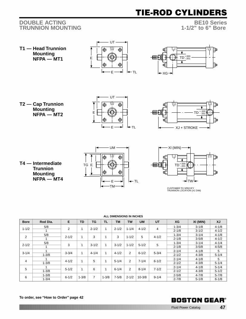
Fluid Power Catalog 47
TIE-ROD CYLINDERS
To order, see “How to Order” page 42
DOUBLE ACTING BE10 SeriesTRUNNION MOUNTING 1-1/2" to 6" Bore
T1 — Head TrunnionMountingNFPA — MT1
UT
TLE XG
TD .000.001
+-E
T2 — Cap TrunnionMountingNFPA — MT2
XJ + STROKE
UT
TLE
TDE .000.001
+-
T4 — IntermediateTrunnionMountingNFPA — MT4 TW
TD
XI (MIN)
.000
.001+-
CUSTOMER TO SPECIFYTRUNNION LOCATION (X1 DIM)
UM
TLE
E
TM
TG
ALL DIMENSIONS IN INCHES
Bore Rod Dia. E TD TG TL TM TW UM UT XG XI (MIN) XJ
1-1/25/8
2 1 2-1/2 1 2-1/2 1-1/4 4-1/2 41-3/4 3-1/8 4-1/8
1 2-1/8 3-1/2 4-1/2
25/8
2-1/2 1 3 1 3 1-1/2 5 4-1/21-3/4 3-1/4 4-1/8
1 2-1/8 3-5/8 4-1/2
2-1/25/8
3 1 3-1/2 1 3-1/2 1-1/2 5-1/2 51-3/4 3-1/4 4-1/4
1 2-1/8 3-5/8 4-5/8
3-1/41
3-3/4 1 4-1/4 1 4-1/2 2 6-1/2 5-3/42-1/4 4-1/8 5
1-3/8 2-1/2 4-3/8 5-1/4
41
4-1/2 1 5 1 5-1/4 2 7-1/4 6-1/22-1/4 4-1/8 5
1-3/8 2-1/2 4-3/8 5-1/4
51
5-1/2 1 6 1 6-1/4 2 8-1/4 7-1/22-1/4 4-1/8 5-1/4
1-3/8 2-1/2 4-3/8 5-1/2
61-3/8
6-1/2 1-3/8 7 1-3/8 7-5/8 2-1/2 10-3/8 9-1/42-5/8 4-7/8 5-7/8
1-3/4 2-7/8 5-1/8 6-1/8
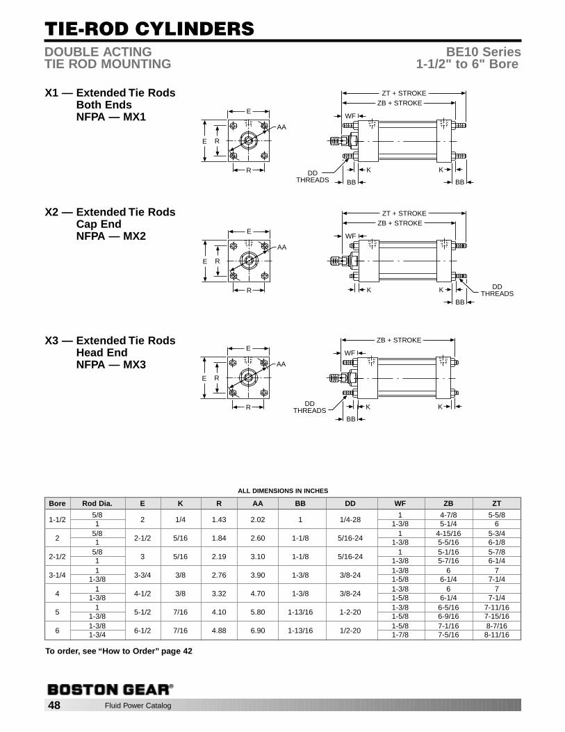
48 Fluid Power Catalog
TIE-ROD CYLINDERS
To order, see “How to Order” page 42
DOUBLE ACTING BE10 SeriesTIE ROD MOUNTING 1-1/2" to 6" Bore
X1 — Extended Tie RodsBoth EndsNFPA — MX1
R
E
E R
ZB + STROKE
AA
BB
K
BB
K
WF
DDTHREADS
ZT + STROKE
X2 — Extended Tie RodsCap EndNFPA — MX2
ZB + STROKE
K
BB
K
WF
DDTHREADS
ZT + STROKE
R
E
E R
AA
X3 — Extended Tie RodsHead EndNFPA — MX3
ZB + STROKE
K
BB
K
WF
DDTHREADSR
E
E R
AA
ALL DIMENSIONS IN INCHES
Bore Rod Dia. E K R AA BB DD WF ZB ZT
1-1/25/8
2 1/4 1.43 2.02 1 1/4-281 4-7/8 5-5/8
1 1-3/8 5-1/4 6
25/8
2-1/2 5/16 1.84 2.60 1-1/8 5/16-241 4-15/16 5-3/4
1 1-3/8 5-5/16 6-1/8
2-1/25/8
3 5/16 2.19 3.10 1-1/8 5/16-241 5-1/16 5-7/8
1 1-3/8 5-7/16 6-1/4
3-1/41
3-3/4 3/8 2.76 3.90 1-3/8 3/8-241-3/8 6 7
1-3/8 1-5/8 6-1/4 7-1/4
41
4-1/2 3/8 3.32 4.70 1-3/8 3/8-241-3/8 6 7
1-3/8 1-5/8 6-1/4 7-1/4
51
5-1/2 7/16 4.10 5.80 1-13/16 1-2-201-3/8 6-5/16 7-11/16
1-3/8 1-5/8 6-9/16 7-15/16
61-3/8
6-1/2 7/16 4.88 6.90 1-13/16 1/2-201-5/8 7-1/16 8-7/16
1-3/4 1-7/8 7-5/16 8-11/16
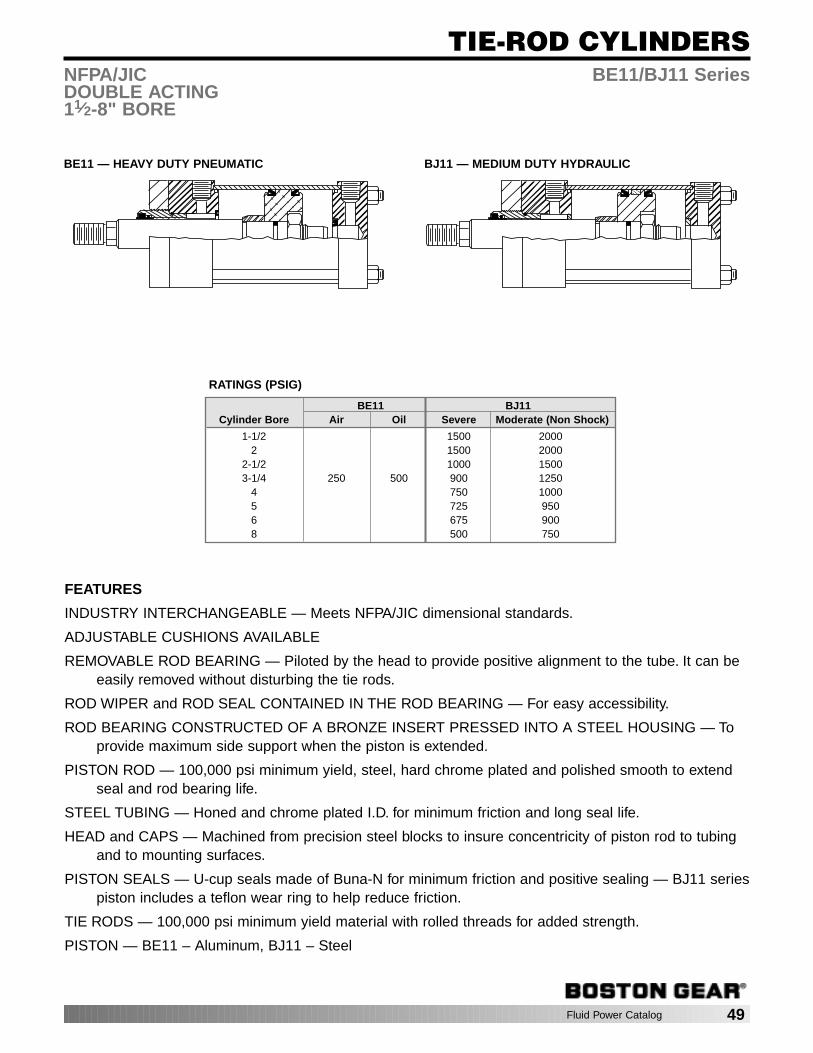
Fluid Power Catalog 49
TIE-ROD CYLINDERSNFPA/JIC BE11/BJ11 SeriesDOUBLE ACTING11⁄2-8" BORE
FEATURES
INDUSTRY INTERCHANGEABLE — Meets NFPA/JIC dimensional standards.
ADJUSTABLE CUSHIONS AVAILABLE
REMOVABLE ROD BEARING — Piloted by the head to provide positive alignment to the tube. It can beeasily removed without disturbing the tie rods.
ROD WIPER and ROD SEAL CONTAINED IN THE ROD BEARING — For easy accessibility.
ROD BEARING CONSTRUCTED OF A BRONZE INSERT PRESSED INTO A STEEL HOUSING — Toprovide maximum side support when the piston is extended.
PISTON ROD — 100,000 psi minimum yield, steel, hard chrome plated and polished smooth to extendseal and rod bearing life.
STEEL TUBING — Honed and chrome plated I.D. for minimum friction and long seal life.
HEAD and CAPS — Machined from precision steel blocks to insure concentricity of piston rod to tubingand to mounting surfaces.
PISTON SEALS — U-cup seals made of Buna-N for minimum friction and positive sealing — BJ11 seriespiston includes a teflon wear ring to help reduce friction.
TIE RODS — 100,000 psi minimum yield material with rolled threads for added strength.
PISTON — BE11 – Aluminum, BJ11 – Steel
BE11 BJ11Cylinder Bore Air Oil Severe Moderate (Non Shock)
1-1/2 1500 20002 1500 2000
2-1/2 1000 15003-1/4 250 500 900 1250
4 750 10005 725 9506 675 9008 500 750
RATINGS (PSIG)
BE11 — HEAVY DUTY PNEUMATIC BJ11 — MEDIUM DUTY HYDRAULIC

50 Fluid Power Catalog
TIE-ROD CYLINDERS
BE11 — HEAVY DUTY, PNEUMATICBJ11 — MEDIUM DUTY, HYDRAULIC
HOW TO ORDER BE11/BJ11 SERIES CYLINDERS
To develop a Cylinder Order Number, select only those Code Numbersthat represent the cylinder required, and place in the sequence shownbelow:
EXAMPLE: Required Cylinder — Heavy Duty Air Cylinder, 4" Bore,Detachable Clevis (NFPA Mounting MP2), Standard Rod,Adjustable Cushion Head End, Standard Port location, 73"of Stroke, 1" Standard Rod Diameter, 1-14 Full DiameterRod Threads.
SPECIFYBE11 40 P2 2 1 73 0 02
DOUBLE ACTING BE11/BJ11 Series
Series
BE11Pneumatic
BJ11Hydraulic
Code BoreNo. DIa.
15 - 1-1/220 - 225 - 2-1/232 - 3-1/440 - 450 - 560 - 680 - 8
Code NFPANo. Mounting Des.
BX - None (Basic Cylinder) —DBX - Double Rod (Basic Cylinder) —E3 - Head Square (8" bore only) ME3E4 - Cap Square (8" bore only) ME4F1 - Head Rectangular Flange* MF1F2 - Cap Rectangular Flange* MF2F5 - Head Square Flange* MF5F6 - Cap Square Flange* MF6P1 - Cap Fixed Clevis MP1P2 - Cap Detachable Clevis* MP2P3 - Cap Fixed Eye MP3S2 - Side Lugs MS2S4 - Side Tapped MS4S7 - Side End Lugs MS7T1 - Head Trunnion MT1T2 - Cap Trunnion MT2T4 - Intermediate Trunnion MT4X1 - Extended Tie Rods-Both Ends MX1X2 - Extended Tie Rods-Cap End MX2X3 - Extended Tie Rods-Head End MX3
Code CushionsNo. and Rod
Standard RodDiameter
1 - Non Cushioned2 - Cushioned
Head End3 - Cushioned
Cap End4 - Cushioned
Both Ends1st Oversize
Rod Diameter5 - Non Cushioned6 - Cushioned
Head End7 - Cushioned
Cap End8 - Cushioned
Both Ends9 - 2nd Oversize
Rods andlarger-Specify
Code PortNo. Positions**
1 - StandardPort Position
2 - 90° ClockwisePort Position
3 - 180° ClockwisePort Position
4 - 270° ClockwisePort Position
Stroke inCode WholeNo. Inches
01 - 1 inch05 - 512 -1225 - 2530 - 3043 - 4366 - 66
etc.
FractionalCode StrokeNo. Length
0 - No fraction1 - 1/8 inch2 - 1/43 - 3/84 - 1/25 - 5/86 - 3/47 - 7/89 - For
fractionsnot shown- Specify
Code ModificationNo. Descriptions
- Style 1StandardThread (codenot required —leave blank)
02 - Style 2 RodEnd — Fulldiameter Male Th’d.
03 - Style 3 RodEnd — Female Th’d.
04 - Style 4 RodEnd —OptionalShoulder, Male Th’d.
XX - Special(Specify)
Add D to mounting for Double Rod ex. DS4 **View facing Rod End.*Not available for 8" bore.
ROD DIAMETERS AVAILABLERod Bore Dia.Dia. 1-1/2 2 2-1/2 3-1/4 4 5 6 8
5/8 STD STD STD — — — — —1 1st OS† 1st OS 1st OS STD STD STD — —
1-3/8 — A A 1st OS 1st OS 1st OS STD STD1-3/4 — — A A A A 1st OS 1st OS
2 — — — A A A A A2-1/2 — — — — A A A A
3 — — — — — A A A3-1/2 — — — — — A A A
4 — — — — — — A A4-1/2 — — — — — — — A
5 — — — — — — — A5-1/2 — — — — — — — A
STD — Standard Rod Diameter; 1st OS — First Oversized Rod DiameterA — Available Rod Diameters, Consult Factory†Adjustable cushion not available on head end; 1-1/2 bore with 1" rod diameter.

Fluid Power Catalog 51
TIE-ROD CYLINDERS
To order, see “How to Order” page 50
BX — Basic Mounting
DOUBLE ACTING BE11/BJ11 SeriesBASIC MOUNTING 1-1/2" to 8" Bore
E
E
ZB + STROKE
WF
G
JK
VF
MM
F
LB + STROKE
P + STROKEY
EE (NPTF)
2
3
1
4
K
DBX — Double RodBasic Mounting E
E
ZM + 2 X STROKE
WFG G
K
VF
MM
F
LD + STROKE
P + STROKEY
EE (NPTF)
WF+
STROKE
VF
F
K
MM2
3
1
4
Y + STROKE
Style 1Standard unless
otherwise specified
Style 2Full Diameter Male Thread
Style 3Female Thread
WFA
KK
CVF
D
MM
NA
B-.001-.003
ACROSSFLATS
WFA
CC
CVF
D
MMB
-.001-.003
ACROSS FLATS
WF
KK
C VF
D
MMB
-.001-.003
ACROSS FLATS
A
Style 4Optional Shouldered
Male ThreadWFA
LL
C
VF
D
MM
NA
B-.001-.003
ACROSSFLATS
ALL DIMENSIONS IN INCHES
Bore E EE (NPTF) F G J K LB LD P
1-1/2 2 3/8-18 3/8 1-1/2 1 1/4 3-5/8 4-1/8 2-1/42 2-1/2 3/8-18 3/8 1-1/2 1 5/16 3-5/8 4-1/8 2-1/4
2-1/2 3 3/8-18 3/8 1-1/2 1 5/16 3-3/4 4-1/4 2-3/83-1/4 3-3/4 1/2-14 5/8 1-3/4 1-1/4 3/8 4-1/4 4-3/4 2-5/8
4 4-1/2 1/2-14 5/8 1-3/4 1-1/4 3/8 4-1/4 4-3/4 2-5/85 5-1/2 1/2-14 5/8 1-3/4 1-1/4 7/16 4-1/2 5 2-7/86 6-1/2 3/4-14 3/4 2 1-1/2 7/16 5 5-1/2 3-1/88 8-1/2 3/4-14 3/4 2 1-1/2 9/16 5-1/8 5-5/8 3-1/4
Rod ThreadBore Dia.(MM) CC KK* LL A B C D NA VF WF Y ZB ZM
1-1/25/8 5/8-18 7/16-20 1/2-20 3/4 1-1/8 3/8 1/2 19/32 5/8 1 1-15/16 4-7/8 6-1/81 1-14 3/4-16 7/8-14 1-1/8 1-1/2 1/2 7/8 31/32 7/8 1-3/8 2-5/16 5-1/4 6-7/8
25/8 5/8-18 7/16-20 1/2-20 3/4 1-1/8 3/8 1/2 19/32 5/8 1 1-15/16 4-15/16 6-1/81 1-14 3/4-16 7/8-14 1-1/8 1-1/2 1/2 7/8 31/32 7/8 1-3/8 2-5/16 5-5/16 6-7/8
2-1/25/8 5/8-18 7/16-20 1/2-20 3/4 1-1/8 3/8 1/2 19/32 5/8 1 1-15/16 5-1/16 6-1/41 1-14 3/4-16 7/8-14 1-1/8 1-1/2 1/2 7/8 31/32 7/8 1-3/8 2-5/16 5-7/16 7
3-1/41 1-14 3/4-16 7/8-14 1-1/8 1-1/2 1/2 7/8 31/32 7/8 1-3/8 2-7/16 6 7-1/2
1-3/8 1-3/8-12 1-14 1-1/4-12 1-5/8 2 5/8 1-1/8 1-11/32 1 1-5/8 2-11/16 6-1/4 8
41 1-14 3/4-16 7/8-14 1-1/8 1-1/2 1/2 7/8 31/32 7/8 1-3/8 2-7/16 6 7-1/2
1-3/8 1-3/8-12 1-14 1-1/4-12 1-5/8 2 5/8 1-1/8 1-11/32 1 1-5/8 2-11/16 6-1/4 8
51 1-14 3/4-16 7/8-14 1-1/8 1-1/2 1/2 7/8 31/32 7/8 1-3/8 2-7/16 6-5/16 7-3/4
1-3/8 1-3/8-12 1-14 1-1/4-12 1-5/8 2 5/8 1-1/8 1-11/32 1 1-5/8 2-11/16 6-9/16 8-1/4
61-3/8 1-3/8-12 1-14 1-1/4-12 1-5/8 2 5/8 1-1/8 1-11/32 1 1-5/8 2-13/16 7-1/16 8-3/41-3/4 1-3/4-12 1-1/4-12 1-1/2-12 2 2-3/8 3/4 1-1/2 1-23/32 1-1/8 1-7/8 3-1/16 7-5/16 9-1/4
81-3/8 1-3/8-12 1-14 1-1/4-12 1-5/8 2 5/8 1-1/8 1-11/32 1 1-5/8 2-13/16 7-5/16 8-7/81-3/4 1-3/4-12 1-1/4-12 1-1/2-12 2 2-3/8 3/4 1-1/2 1-23/32 1-1/8 1-7/8 3-1/16 7-9/16 9-3/8
*Standard thread — other threads available.
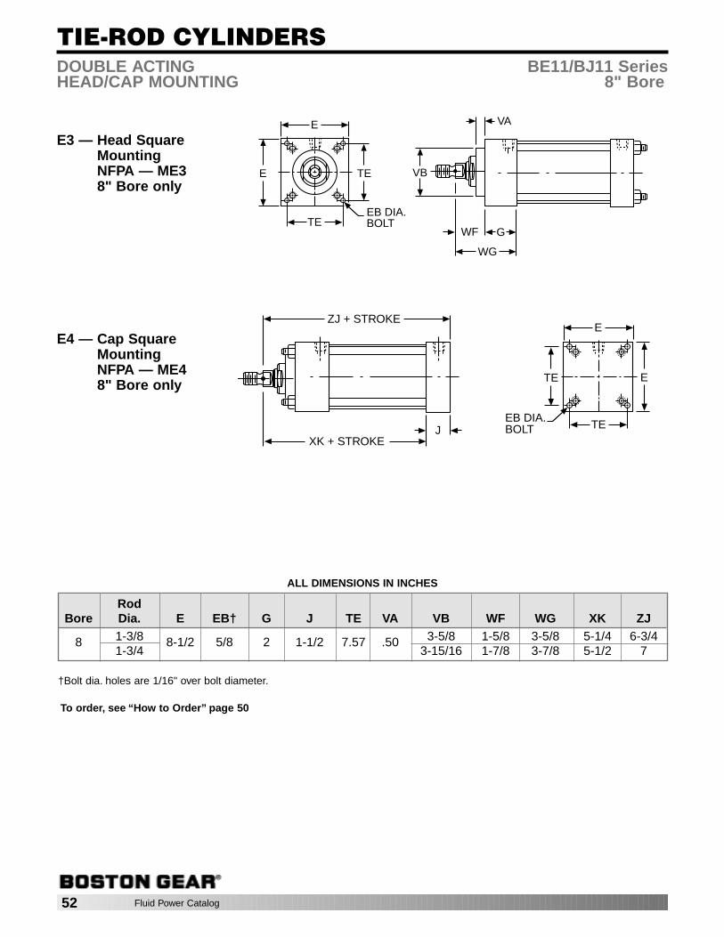
52 Fluid Power Catalog
TIE-ROD CYLINDERS
To order, see “How to Order” page 50
DOUBLE ACTING BE11/BJ11 SeriesHEAD/CAP MOUNTING 8" Bore
E3 — Head SquareMountingNFPA — ME38" Bore only
E
E
WF G
VB
VA
TE
TEEB DIA.BOLT
WG
E4 — Cap SquareMountingNFPA — ME48" Bore only
E
ETE
TEEB DIA.BOLTJ
ZJ + STROKE
XK + STROKE
ALL DIMENSIONS IN INCHES
Rod Bore Dia. E EB† G J TE VA VB WF WG XK ZJ
8 1-3/8 8-1/2 5/8 2 1-1/2 7.57 .50 3-5/8 1-5/8 3-5/8 5-1/4 6-3/41-3/4 3-15/16 1-7/8 3-7/8 5-1/2 7
†Bolt dia. holes are 1/16" over bolt diameter.
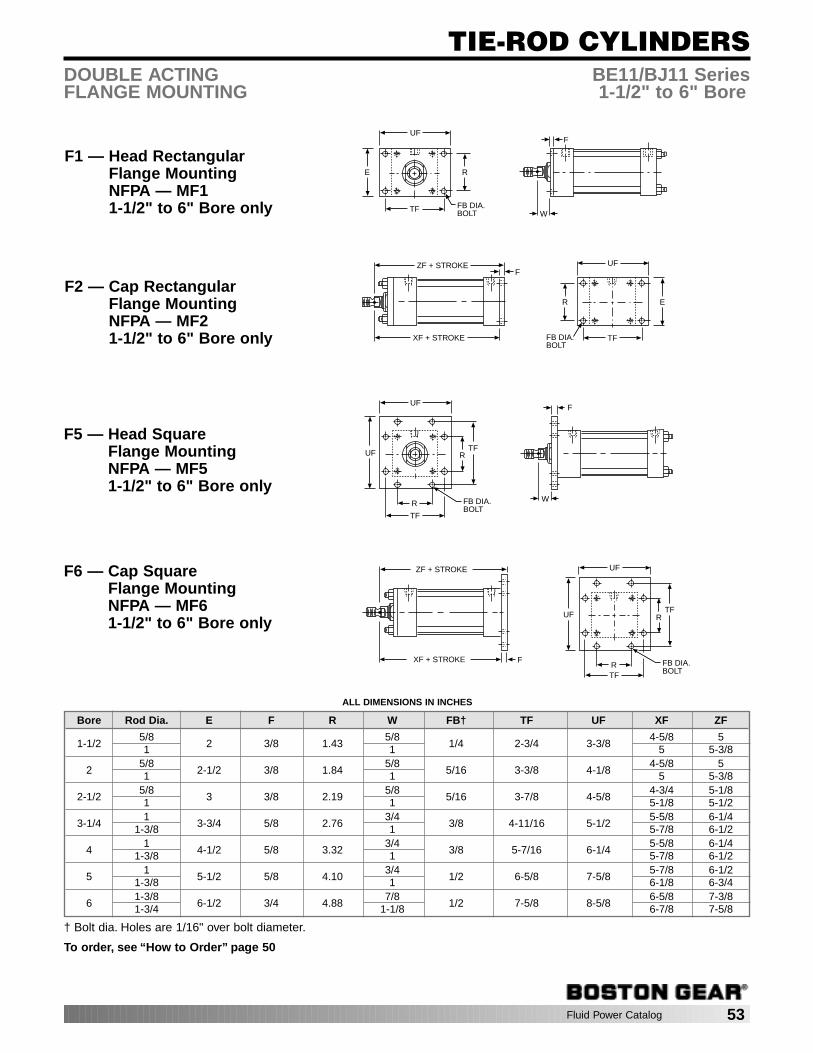
Fluid Power Catalog 53
TIE-ROD CYLINDERS
To order, see “How to Order” page 50
DOUBLE ACTING BE11/BJ11 SeriesFLANGE MOUNTING 1-1/2" to 6" Bore
F1 — Head RectangularFlange MountingNFPA — MF11-1/2" to 6" Bore only
R
FB DIA. BOLT
E
TFW
FUF
F2 — Cap RectangularFlange MountingNFPA — MF21-1/2" to 6" Bore only
R
FB DIA.BOLT
E
TF
UFZF + STROKE
XF + STROKE
F
F5 — Head SquareFlange MountingNFPA — MF51-1/2" to 6" Bore only
F
R
FB DIA.BOLT
UF
TF
UF
R
TF
W
F6 — Cap SquareFlange MountingNFPA — MF61-1/2" to 6" Bore only R
FB DIA.BOLT
UF
TF
UF
R
TF
F
ZF + STROKE
XF + STROKE
ALL DIMENSIONS IN INCHES
Bore Rod Dia. E F R W FB† TF UF XF ZF
1-1/25/8
2 3/8 1.435/8
1/4 2-3/4 3-3/84-5/8 5
1 1 5 5-3/8
25/8
2-1/2 3/8 1.845/8
5/16 3-3/8 4-1/84-5/8 5
1 1 5 5-3/8
2-1/25/8
3 3/8 2.195/8
5/16 3-7/8 4-5/84-3/4 5-1/8
1 1 5-1/8 5-1/2
3-1/41
3-3/4 5/8 2.763/4
3/8 4-11/16 5-1/25-5/8 6-1/4
1-3/8 1 5-7/8 6-1/2
41
4-1/2 5/8 3.323/4
3/8 5-7/16 6-1/45-5/8 6-1/4
1-3/8 1 5-7/8 6-1/2
51
5-1/2 5/8 4.103/4
1/2 6-5/8 7-5/85-7/8 6-1/2
1-3/8 1 6-1/8 6-3/4
61-3/8
6-1/2 3/4 4.887/8
1/2 7-5/8 8-5/86-5/8 7-3/8
1-3/4 1-1/8 6-7/8 7-5/8
† Bolt dia. Holes are 1/16" over bolt diameter.

54 Fluid Power Catalog
TIE-ROD CYLINDERS
To order, see “How to Order” page 50
DOUBLE ACTING BE11/BJ11 SeriesCLEVIS MOUNTING 1-1/2" to 8" Bore
P1 — Cap FixedClevis MountingNFPA — MP1 E
CB
CWCWCW
E
M
ZC + STROKE
XC + STROKE
CD
LR
MR
L
P2 — Cap DetachableClevis MountingNFPA — MP2
M
ZD + STROKE
XD + STROKE
E
CB
CW
CD
MR
CW
E
F
L
LR
P3 — Cap FixedEye MountingNFPA — MP3
M
ZC + STROKE
XC + STROKE
ECD
LR
MRE
L EW
ALL DIMENSIONS IN INCHES
Bore Rod Dia. E F L M CB CD CW EW LR MR XC XD ZC ZD
1-1/25/8
2 3/8 3/4 1/2 3/4 1/2 1/2 3/4 5/8 19/325-3/8 5-3/4 5-7/8 6-1/4
1 5-3/4 6-1/8 6-1/4 6-5/8
25/8
2-1/2 3/8 3/4 1/2 3/4 1/2 1/2 3/4 5/8 19/325-3/8 5-3/4 5-7/8 6-1/4
1 5-3/4 6-1/8 6-1/4 6-5/8
2-1/25/8
3 3/8 3/4 1/2 3/4 1/2 1/2 3/4 5/8 19/325-1/2 5-7/8 6 6-3/8
1 5-7/8 6-1/4 6-3/8 6-3/4
3-1/41
3-3/4 5/8 1-1/4 3/4 1-1/4 3/4 5/8 1-1/4 1 7/86-7/8 7-1/2 7-5/8 8-1/4
1-3/8 7-1/8 7-3/4 7-7/8 8-1/2
41
4-1/2 5/8 1-1/4 3/4 1-1/4 3/4 5/8 1-1/4 1 7/86-7/8 7-1/2 7-5/8 8-1/4
1-3/8 7-1/8 7-3/4 7-7/8 8-1/2
51
5-1/2 5/8 1-1/4 3/4 1-1/4 3/4 5/8 1-1/4 1 7/87-1/8 7-3/4 7-7/8 8-1/2
1-3/8 7-3/8 8 8-1/8 8-3/4
61-3/8
6-1/2 3/4 1-1/2 1 1-1/2 1 3/4 1-1/2 1-1/4 1-7/328-1/8 8-7/8 9-1/8 9-7/8
1-3/4 8-3/8 9-1/8 9-3/8 10-1/8
81-3/8
8-1/2 3/4 1-1/2 1 1-1/2 1 3/4 1-1/2 1-1/4 1-7/328-1/4 9-1/4 9-1/4 10-1/4
1-3/4 8-1/2 9-1/2 9-1/2 10-1/2
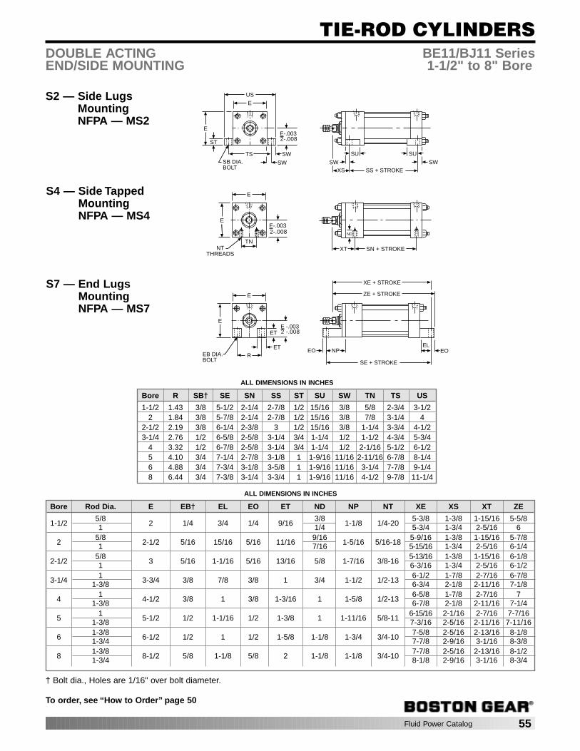
Fluid Power Catalog 55
TIE-ROD CYLINDERS
To order, see “How to Order” page 50
DOUBLE ACTING BE11/BJ11 SeriesEND/SIDE MOUNTING 1-1/2" to 8" Bore
S2 — Side LugsMountingNFPA — MS2
SS + STROKEXSSW
SU SU
SW
E
E
US
ST
TS SW
SWSB DIA.BOLT
E-.0032-.008
S4 — Side TappedMountingNFPA — MS4
SN + STROKEXT
ND
E
E
TNNT
THREADS
E-.0032-.008
S7 — End LugsMountingNFPA — MS7
SE + STROKE
EO NP
E
E
ET
RET
EB DIA.BOLT
ELEO
E -.0032 -.008
ZE + STROKE
XE + STROKE
ALL DIMENSIONS IN INCHES
Bore Rod Dia. E EB† EL EO ET ND NP NT XE XS XT ZE
1-1/25/8
2 1/4 3/4 1/4 9/163/8
1-1/8 1/4-205-3/8 1-3/8 1-15/16 5-5/8
1 1/4 5-3/4 1-3/4 2-5/16 6
25/8
2-1/2 5/16 15/16 5/16 11/169/16
1-5/16 5/16-185-9/16 1-3/8 1-15/16 5-7/8
1 7/16 5-15/16 1-3/4 2-5/16 6-1/4
2-1/25/8
3 5/16 1-1/16 5/16 13/16 5/8 1-7/16 3/8-165-13/16 1-3/8 1-15/16 6-1/8
1 6-3/16 1-3/4 2-5/16 6-1/2
3-1/41
3-3/4 3/8 7/8 3/8 1 3/4 1-1/2 1/2-136-1/2 1-7/8 2-7/16 6-7/8
1-3/8 6-3/4 2-1/8 2-11/16 7-1/8
41
4-1/2 3/8 1 3/8 1-3/16 1 1-5/8 1/2-136-5/8 1-7/8 2-7/16 7
1-3/8 6-7/8 2-1/8 2-11/16 7-1/4
51
5-1/2 1/2 1-1/16 1/2 1-3/8 1 1-11/16 5/8-116-15/16 2-1/16 2-7/16 7-7/16
1-3/8 7-3/16 2-5/16 2-11/16 7-11/16
61-3/8
6-1/2 1/2 1 1/2 1-5/8 1-1/8 1-3/4 3/4-107-5/8 2-5/16 2-13/16 8-1/8
1-3/4 7-7/8 2-9/16 3-1/16 8-3/8
81-3/8
8-1/2 5/8 1-1/8 5/8 2 1-1/8 1-1/8 3/4-107-7/8 2-5/16 2-13/16 8-1/2
1-3/4 8-1/8 2-9/16 3-1/16 8-3/4
ALL DIMENSIONS IN INCHES
Bore R SB† SE SN SS ST SU SW TN TS US
1-1/2 1.43 3/8 5-1/2 2-1/4 2-7/8 1/2 15/16 3/8 5/8 2-3/4 3-1/22 1.84 3/8 5-7/8 2-1/4 2-7/8 1/2 15/16 3/8 7/8 3-1/4 4
2-1/2 2.19 3/8 6-1/4 2-3/8 3 1/2 15/16 3/8 1-1/4 3-3/4 4-1/23-1/4 2.76 1/2 6-5/8 2-5/8 3-1/4 3/4 1-1/4 1/2 1-1/2 4-3/4 5-3/4
4 3.32 1/2 6-7/8 2-5/8 3-1/4 3/4 1-1/4 1/2 2-1/16 5-1/2 6-1/25 4.10 3/4 7-1/4 2-7/8 3-1/8 1 1-9/16 11/16 2-11/16 6-7/8 8-1/46 4.88 3/4 7-3/4 3-1/8 3-5/8 1 1-9/16 11/16 3-1/4 7-7/8 9-1/48 6.44 3/4 7-3/8 3-1/4 3-3/4 1 1-9/16 11/16 4-1/2 9-7/8 11-1/4
† Bolt dia., Holes are 1/16" over bolt diameter.

56 Fluid Power Catalog
TIE-ROD CYLINDERS
To order, see “How to Order” page 50
DOUBLE ACTING BE11/BJ11 SeriesTRUNNION MOUNTING 1-1/2" to 8" Bore
T1 — Head TrunnionMountingNFPA — MT1
UT
TLE
TDE .000.001
+-
XG
T2 — Cap TrunnionMountingNFPA — MT2
XJ + STROKE
UT
TLE
TDE
J1
.000
.001+-
T4 — Intermediate TrunnionMountingNFPA — MT4
TW
UM
TLE
TD
TM
TG
XI (MIN)
CUSTOMER TO SPECIFYTRUNNION LOCATION (XI DIM)
.000
.001+-E
ALL DIMENSIONS IN INCHES
Bore Rod Dia. E J1 TD TG TL TM TW UM UT XG XI (MIN) XJ
1-1/25/8
2 1-1/8* 1 2-1/2 1 2-1/2 1-1/4 4-1/2 41-3/4 3-1/8 4-1/4
1 2-1/8 3-1/2 4-5/8
25/8
2-1/2 1-1/8* 1 3 1 3 1-1/2 5 4-1/21-3/4 3-1/4 4-1/4
1 2-1/8 3-5/8 4-5/8
2-1/25/8
3 1-1/8* 1 3-1/2 1 3-1/2 1-1/2 5-1/2 51-3/4 3-1/4 4-3/8
1 2-1/8 3-5/8 4-3/4
3-1/41
3-3/4 1-1/4 1 4-1/4 1 4-1/2 2 6-1/2 5-3/42-1/4 4-1/8 5
1-3/8 2-1/2 4-3/8 5-1/4
41
4-1/2 1-1/4 1 5 1 5-1/4 2 7-1/4 6-1/22-1/4 4-1/8 5
1-3/8 2-1/2 4-3/8 5-1/4
51
5-1/2 1-1/4 1 6 1 6-1/4 2 8-1/4 7-1/22-1/4 4-1/8 5-1/4
1-3/8 2-1/2 4-3/8 5-1/2
61-3/8
6-1/2 1-1/2 1-3/8 7 1-3/8 7-5/8 2-1/2 10-3/8 9-1/42-5/8 4-7/8 5-7/8
1-3/4 2-7/8 5-1/8 6-1/8
81-3/8
8-1/2 1-1/2 1-3/8 9-1/2 1-3/8 9-3/4 2-1/2 12-1/2 11-1/42-5/8 4-7/8 6
1-3/4 2-7/8 5-1/8 6-1/4
* Dimension exceeds NFPA by 1/8".
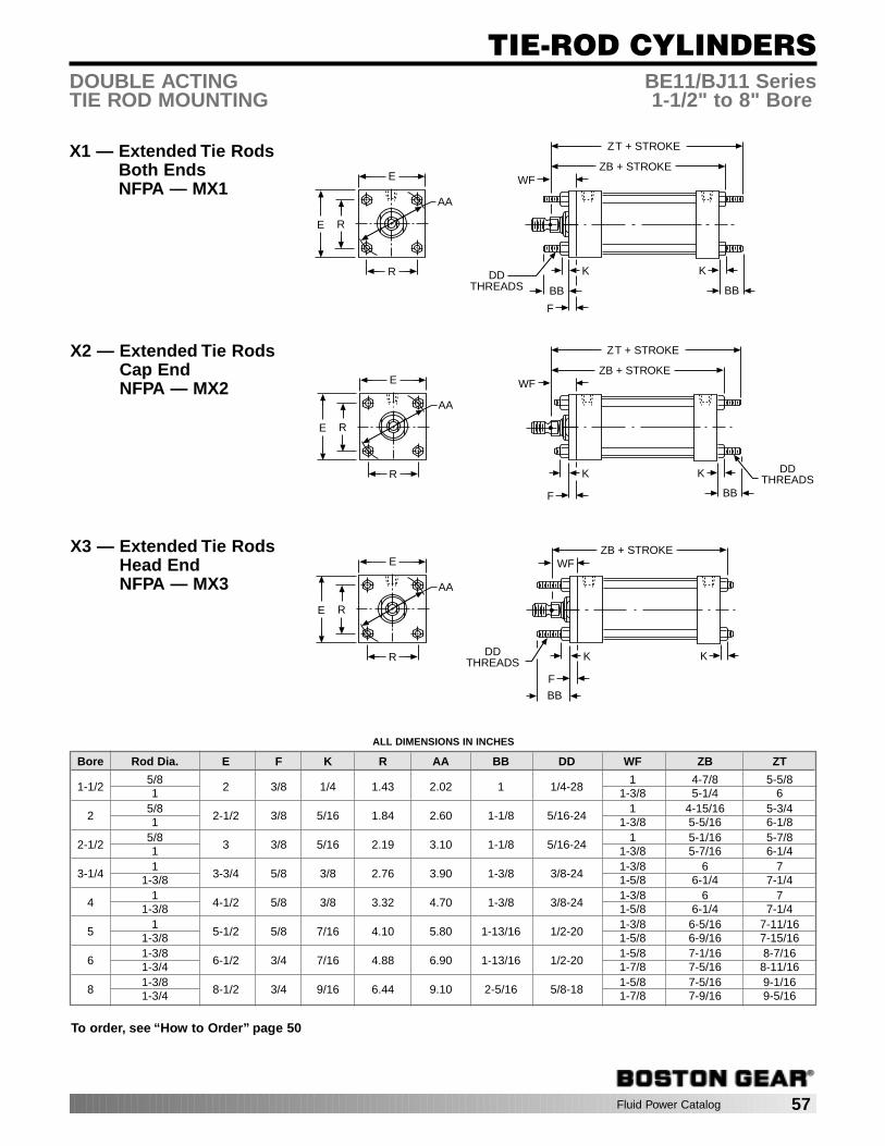
Fluid Power Catalog 57
TIE-ROD CYLINDERS
To order, see “How to Order” page 50
DOUBLE ACTING BE11/BJ11 SeriesTIE ROD MOUNTING 1-1/2" to 8" Bore
X1 — Extended Tie RodsBoth EndsNFPA — MX1
R
E
E R
ZB + STROKE
AA
BB
K
BB
K
WF
F
ZT + STROKE
DDTHREADS
X2 — Extended Tie RodsCap EndNFPA — MX2
ZB + STROKE
K
BB
K
WF
F
ZT + STROKE
DDTHREADSR
E
E R
AA
X3 — Extended Tie RodsHead EndNFPA — MX3
R
E
E R
AA
ALL DIMENSIONS IN INCHES
Bore Rod Dia. E F K R AA BB DD WF ZB ZT
1-1/25/8
2 3/8 1/4 1.43 2.02 1 1/4-281 4-7/8 5-5/8
1 1-3/8 5-1/4 6
25/8
2-1/2 3/8 5/16 1.84 2.60 1-1/8 5/16-241 4-15/16 5-3/4
1 1-3/8 5-5/16 6-1/8
2-1/25/8
3 3/8 5/16 2.19 3.10 1-1/8 5/16-241 5-1/16 5-7/8
1 1-3/8 5-7/16 6-1/4
3-1/41
3-3/4 5/8 3/8 2.76 3.90 1-3/8 3/8-241-3/8 6 7
1-3/8 1-5/8 6-1/4 7-1/4
41
4-1/2 5/8 3/8 3.32 4.70 1-3/8 3/8-241-3/8 6 7
1-3/8 1-5/8 6-1/4 7-1/4
51
5-1/2 5/8 7/16 4.10 5.80 1-13/16 1/2-201-3/8 6-5/16 7-11/16
1-3/8 1-5/8 6-9/16 7-15/16
61-3/8
6-1/2 3/4 7/16 4.88 6.90 1-13/16 1/2-201-5/8 7-1/16 8-7/16
1-3/4 1-7/8 7-5/16 8-11/16
81-3/8
8-1/2 3/4 9/16 6.44 9.10 2-5/16 5/8-181-5/8 7-5/16 9-1/16
1-3/4 1-7/8 7-9/16 9-5/16
ZB + STROKE
K K
WF
F
DDTHREADS
BB

58 Fluid Power Catalog
12 2 1 3 4 8 5
13
9 7 11 6 8 10
14
15
NOT SHOWN:
WEAR RING PISTON
O-RING, CUSHION
TIE ROD CYLINDERSREPAIR PARTS
BE10 Series shown forexample
All cylinders are differentyet similar in construction
BE10 Series
Body Kit includes: all seals required torebuild the cylinder body and bearing car-tridge for the standard and first oversize rod.For this reason, extra seals are included andyou should not use every seal.
Rod Kit includes: Rod Bearing, Bearing O-Ring, Rod Wiper and Rod Packing
To replace all seals — order both theCylinder Service Kit and the Rod Seal Kit.
Number Description
1 Rod Bearing2 Rod Wiper3 Rod Packing4 Bearing O-Ring5 Cushion Seal (Head)6 Cushion Seal (Cap)7 Piston Packing8 Tube Seals
Number Description
9 Piston O-Ring10 Tie Rods (4)11 Tube12 Piston Rod13 Piston14 Wear Ring (BJ11 only)15 O-Ring,
Cushion Screw
BODY KITSSELECT BY BORE DIA.
Bore Catalog ItemDia. Number Code
1-1/2 BE10-15BX4-9003 783252 BE10-20BX4-9003 78327
2-1/2 BE10-25BX4-9003 783293-1/4 BE10-32BX4-9003 78331
4 BE10-40BX4-9003 783335 BE10-50BX4-9003 783356 BE10-60BX4-9003 78337
ROD KITSSELECT BY ROD DIA.
Rod Catalog ItemDia. Number Code
5/8 BE10-15BX4-9002 783261 BE10-32BX4-9002 78328
1-3/8 BE10-60BX4-9002 783301-3/4 BE10-90BX4-9002 78332
2 BE10-92BX4-9002 78334
DESCRIPTIONS:
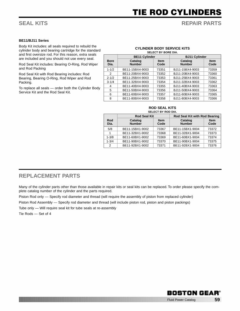
Fluid Power Catalog 59
TIE ROD CYLINDERSSEAL KITS REPAIR PARTS
BE11/BJ11 Series
Body Kit includes: all seals required to rebuild thecylinder body and bearing cartridge for the standardand first oversize rod. For this reason, extra sealsare included and you should not use every seal.
Rod Seal Kit includes: Bearing O-Ring, Rod Wiperand Rod Packing
Rod Seal Kit with Rod Bearing includes: RodBearing, Bearing O-Ring, Rod Wiper and RodPacking.
To replace all seals — order both the Cylinder BodyService Kit and the Rod Seal Kit.
REPLACEMENT PARTS
Many of the cylinder parts other than those available in repair kits or seal kits can be replaced. To order please specify the com-plete catalog number of the cylinder and the parts required.
Piston Rod only — Specify rod diameter and thread (will require the assembly of piston from replaced cylinder)
Piston Rod Assembly — Specify rod diameter and thread (will include piston rod, piston and piston packings)
Tube only — Will require seal kit for tube seals at re-assembly
Tie Rods — Set of 4
CYLINDER BODY SERVICE KITSSELECT BY BORE DIA.
BE11 Cylinder BJ11 CylinderBore Catalog Item Catalog ItemDia. Number Code Number Code
1-1/2 BE11-15BX4-9003 73351 BJ11-15BX4-9003 733592 BE11-20BX4-9003 73352 BJ11-20BX4-9003 73360
2-1/2 BE11-25BX4-9003 73353 BJ11-25BX4-9003 733613-1/4 BE11-32BX4-9003 73354 BJ11-32BX4-9003 73362
4 BE11-40BX4-9003 73355 BJ11-40BX4-9003 733635 BE11-50BX4-9003 73356 BJ11-50BX4-9003 733646 BE11-60BX4-9003 73357 BJ11-60BX4-9003 733658 BE11-80BX4-9003 73358 BJ11-80BX4-9003 73366
ROD SEAL KITSSELECT BY ROD DIA.
Rod Seal Kit Rod Seal Kit with Rod BearingRod Catalog Item Catalog ItemDia. Number Code Number Code
5/8 BE11-15BX1-9002 73367 BE11-15BX1-9004 733721 BE11-32BX1-9002 73368 BE11-32BX1-9004 73373
1-3/8 BE11-60BX1-9002 73369 BE11-60BX1-9004 733741-3/4 BE11-90BX1-9002 73370 BE11-90BX1-9004 73375
2 BE11-92BX1-9002 73371 BE11-92BX1-9004 73376
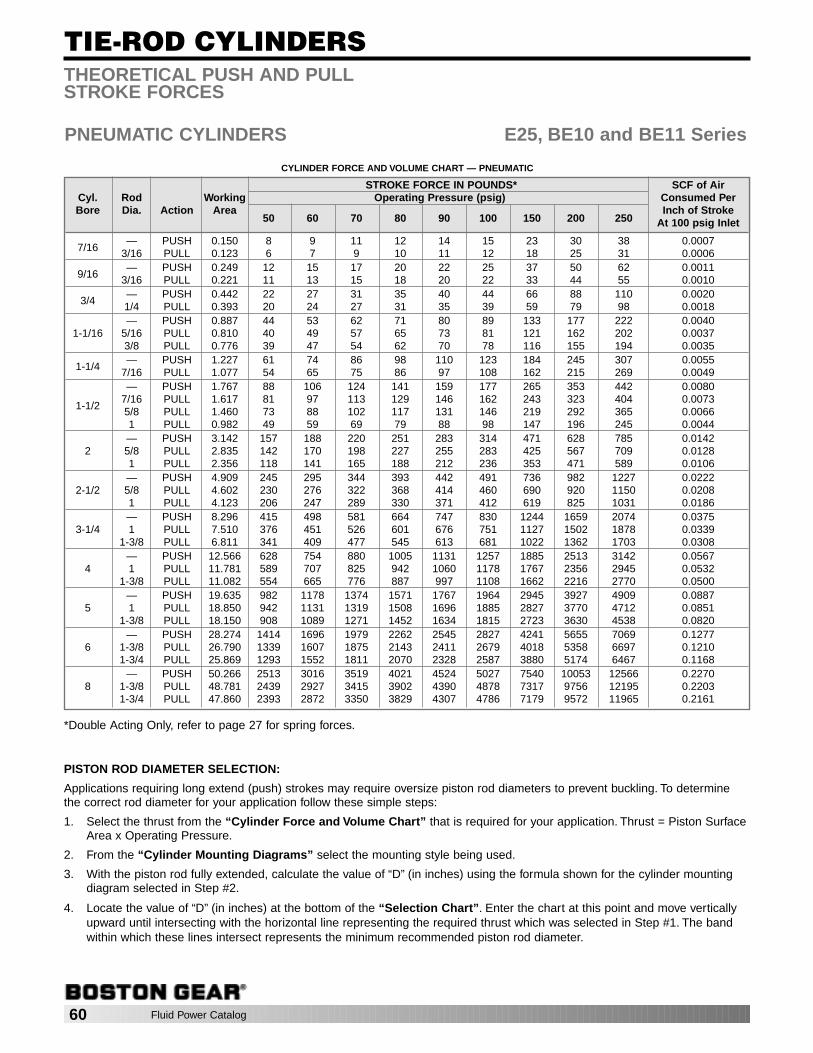
60 Fluid Power Catalog
TIE-ROD CYLINDERS
PNEUMATIC CYLINDERS E25, BE10 and BE11 Series
THEORETICAL PUSH AND PULLSTROKE FORCES
CYLINDER FORCE AND VOLUME CHART — PNEUMATIC
STROKE FORCE IN POUNDS* SCF of AirCyl. Rod Working Operating Pressure (psig) Consumed PerBore Dia. Action Area
50 60 70 80 90 100 150 200 250Inch of Stroke
At 100 psig Inlet
7/16— PUSH 0.150 8 9 11 12 14 15 23 30 38 0.0007
3/16 PULL 0.123 6 7 9 10 11 12 18 25 31 0.0006
9/16— PUSH 0.249 12 15 17 20 22 25 37 50 62 0.0011
3/16 PULL 0.221 11 13 15 18 20 22 33 44 55 0.0010
3/4— PUSH 0.442 22 27 31 35 40 44 66 88 110 0.00201/4 PULL 0.393 20 24 27 31 35 39 59 79 98 0.0018— PUSH 0.887 44 53 62 71 80 89 133 177 222 0.0040
1-1/16 5/16 PULL 0.810 40 49 57 65 73 81 121 162 202 0.00373/8 PULL 0.776 39 47 54 62 70 78 116 155 194 0.0035
1-1/4— PUSH 1.227 61 74 86 98 110 123 184 245 307 0.0055
7/16 PULL 1.077 54 65 75 86 97 108 162 215 269 0.0049— PUSH 1.767 88 106 124 141 159 177 265 353 442 0.0080
1-1/27/16 PULL 1.617 81 97 113 129 146 162 243 323 404 0.00735/8 PULL 1.460 73 88 102 117 131 146 219 292 365 0.00661 PULL 0.982 49 59 69 79 88 98 147 196 245 0.0044— PUSH 3.142 157 188 220 251 283 314 471 628 785 0.0142
2 5/8 PULL 2.835 142 170 198 227 255 283 425 567 709 0.01281 PULL 2.356 118 141 165 188 212 236 353 471 589 0.0106— PUSH 4.909 245 295 344 393 442 491 736 982 1227 0.0222
2-1/2 5/8 PULL 4.602 230 276 322 368 414 460 690 920 1150 0.02081 PULL 4.123 206 247 289 330 371 412 619 825 1031 0.0186— PUSH 8.296 415 498 581 664 747 830 1244 1659 2074 0.0375
3-1/4 1 PULL 7.510 376 451 526 601 676 751 1127 1502 1878 0.03391-3/8 PULL 6.811 341 409 477 545 613 681 1022 1362 1703 0.0308
— PUSH 12.566 628 754 880 1005 1131 1257 1885 2513 3142 0.05674 1 PULL 11.781 589 707 825 942 1060 1178 1767 2356 2945 0.0532
1-3/8 PULL 11.082 554 665 776 887 997 1108 1662 2216 2770 0.0500— PUSH 19.635 982 1178 1374 1571 1767 1964 2945 3927 4909 0.0887
5 1 PULL 18.850 942 1131 1319 1508 1696 1885 2827 3770 4712 0.08511-3/8 PULL 18.150 908 1089 1271 1452 1634 1815 2723 3630 4538 0.0820
— PUSH 28.274 1414 1696 1979 2262 2545 2827 4241 5655 7069 0.12776 1-3/8 PULL 26.790 1339 1607 1875 2143 2411 2679 4018 5358 6697 0.1210
1-3/4 PULL 25.869 1293 1552 1811 2070 2328 2587 3880 5174 6467 0.1168— PUSH 50.266 2513 3016 3519 4021 4524 5027 7540 10053 12566 0.2270
8 1-3/8 PULL 48.781 2439 2927 3415 3902 4390 4878 7317 9756 12195 0.22031-3/4 PULL 47.860 2393 2872 3350 3829 4307 4786 7179 9572 11965 0.2161
*Double Acting Only, refer to page 27 for spring forces.
PISTON ROD DIAMETER SELECTION:
Applications requiring long extend (push) strokes may require oversize piston rod diameters to prevent buckling. To determinethe correct rod diameter for your application follow these simple steps:
1. Select the thrust from the “Cylinder Force and Volume Chart” that is required for your application. Thrust = Piston SurfaceArea x Operating Pressure.
2. From the “Cylinder Mounting Diagrams” select the mounting style being used.
3. With the piston rod fully extended, calculate the value of “D” (in inches) using the formula shown for the cylinder mountingdiagram selected in Step #2.
4. Locate the value of “D” (in inches) at the bottom of the “Selection Chart”. Enter the chart at this point and move verticallyupward until intersecting with the horizontal line representing the required thrust which was selected in Step #1. The bandwithin which these lines intersect represents the minimum recommended piston rod diameter.

Fluid Power Catalog 61
TIE-ROD CYLINDERS
HYDRAULIC CYLINDERS BJ11 SERIES
THEORETICAL PUSH AND PULLSTROKE FORCES
STROKE FORCE IN POUNDS FluidCyl. Rod Working Operating Pressure (psig) Displacement PerBore Size Action Area
50 80 100 250 500 750 1000 1500 2000Inch of Stroke(U.S. Gallons)
— PUSH 1.767 88 141 177 442 884 1325 1767 2651 3534 .00761-1/2 5/8 PULL 1.460 73 117 146 365 730 1095 1460 2191 2921 .0063
1 PULL .982 49 79 98 245 491 736 982 1473 1963 .0042— PUSH 3.142 157 251 314 785 1571 2356 3142 4712 6283 .0136
2 5/8 PULL 2.835 142 227 283 709 1417 2126 2835 4252 5670 .01231 PULL 2.356 118 188 236 589 1178 1767 2356 3534 4712 .0102— PUSH 4.909 245 393 491 1227 2454 3682 4909 7363 .0212
2-1/2 5/8 PULL 4.602 230 368 460 1150 2301 3451 4602 6903 .01991 PULL 4.123 206 330 412 1031 2062 3093 4123 6185 .0178— PUSH 8.296 415 664 830 2074 4148 6222 8296 12444 .0359
3-1/4 1 PULL 7.510 376 601 751 1878 3755 5633 7510 11266 .03251-3/8 PULL 6.811 341 545 681 1703 3405 5108 6811 10216 .0295
— PUSH 12.566 628 1005 1257 3142 6283 9425 12566 .05444 1 PULL 11.781 589 942 1178 2945 5890 8836 11781 .0510
1-3/8 PULL 11.081 554 887 1108 2770 5541 8311 11081 .0480— PUSH 19.635 982 1571 1963 4909 9817 14726 19635 .0850
5 1 PULL 18.850 942 1508 1885 4712 9425 14137 18850 .08161-3/8 PULL 18.150 908 1452 1815 4538 9075 13613 18150 .0786
— PUSH 28.274 1414 2262 2827 7069 14137 21206 28274 .12246 1-3/8 PULL 26.789 1339 2143 2679 6697 13395 20092 26789 .1160
1-3/4 PULL 25.869 1293 2070 2587 6467 12935 19402 25869 .1120— PUSH 50.265 2513 4021 5027 12566 25133 37699 .2176
8 1-3/8 PULL 48.781 2439 3902 4878 12195 24390 36585 .21121-3/4 PULL 47.860 2393 3829 4786 11965 23930 35895 .2072
50,00040,00030,000
20,000
10,0008,0006,0005,0004,0003,000
2,000
1,000800600500400300
200
10080706050200 150 100 50 0
VALVE OF “D” IN INCHES
AX
IAL T
HR
US
T IN
PO
UN
DS
1"DIA.
SELECTION CHART
1 3/4"DIA.
1 3/8"DIA.
5/8"DIA.
UNSUPPORTED ROD END
FIRMLY GUIDED ROD END
SUPPORTED ROD END
BLIND CLEVIS OR REAR TRUNNION MT.
D = 4S
D = 1/2S
D = S
D = D
D = S
D = 4S
D = D
D = 1/2S
SUPPORTED ROD END
UNSUPPORTED ROD END
FIRMLY GUIDED ROD END
ROD TRUNNION
S
S
S
D
S
S
S
D
Cylinder Mounting DiagramsAll Piston Rods Shown in Extended Position
STOP TUBE SELECTION:
Stop tubes enhance the transverse load carrying capability of a long strokecylinder by increasing the distance between the piston and rod bearing at fullextension.
When the value of “D” (calculated from the piston rod diameter selectioninstructions) is less than 40", a stop tube is NOT required. However, if “D” is40" or more, one-inch of stop tube is recommended for every 10" (or fractionthereof) over 40".
CYLINDER FORCE AND VOLUME CHART — HYDRAULIC
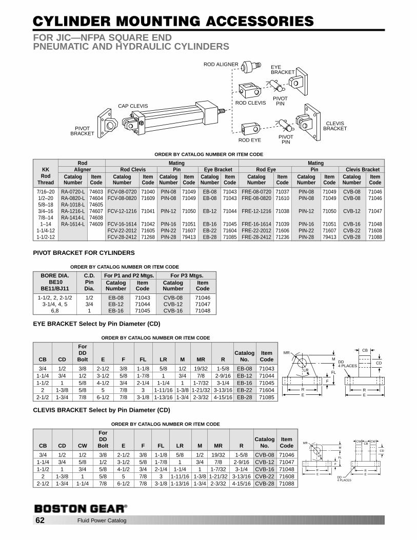
62 Fluid Power Catalog
CYLINDER MOUNTING ACCESSORIESFOR JIC—NFPA SQUARE ENDPNEUMATIC AND HYDRAULIC CYLINDERS
ROD ALIGNER EYEBRACKET
PIVOTPINROD CLEVIS
ROD EYEPIVOT
PIN
CAP CLEVIS
CLEVISBRACKETPIVOT
BRACKET
ORDER BY CATALOG NUMBER OR ITEM CODE
Rod Mating MatingKK Aligner Rod Clevis Pin Eye Bracket Rod Eye Pin Clevis BracketRod Catalog Item Catalog Item Catalog Item Catalog Item Catalog Item Catalog Item Catalog Item
Thread Number Code Number Code Number Code Number Code Number Code Number Code Number Code
7/16–20 RA-0720-L 74603 FCV-08-0720 71040 PIN-08 71049 EB-08 71043 FRE-08-0720 71037 PIN-08 71049 CVB-08 710461/2–20 RA-0820-L 74604 FCV-08-0820 71609 PIN-08 71049 EB-08 71043 FRE-08-0820 71610 PIN-08 71049 CVB-08 710465/8–18 RA-1018-L 746053/4–16 RA-1216-L 74607 FCV-12-1216 71041 PIN-12 71050 EB-12 71044 FRE-12-1216 71038 PIN-12 71050 CVB-12 710477/8–14 RA-1414-L 746081–14 RA-1614-L 74609 FCV-16-1614 71042 PIN-16 71051 EB-16 71045 FRE-16-1614 71039 PIN-16 71051 CVB-16 71048
1-1/4-12 FCV-22-2012 71605 PIN-22 71607 EB-22 71604 FRE-22-2012 71606 PIN-22 71607 CVB-22 716081-1/2-12 FCV-28-2412 71268 PIN-28 79413 EB-28 71085 FRE-28-2412 71236 PIN-28 79413 CVB-28 71088
ORDER BY CATALOG NUMBER OR ITEM CODE
BORE DIA. C.D. For P1 and P2 Mtgs. For P3 Mtgs.BE10 Pin Catalog Item Catalog Item
BE11/BJ11 Dia. Number Code Number Code
1-1/2, 2, 2-1/2 1/2 EB-08 71043 CVB-08 710463-1/4, 4, 5 3/4 EB-12 71044 CVB-12 71047
6,8 1 EB-16 71045 CVB-16 71048
PIVOT BRACKET FOR CYLINDERS
ORDER BY CATALOG NUMBER OR ITEM CODE
ForDD Catalog Item
CB CD Bolt E F FL LR M MR R No. Code
3/4 1/2 3/8 2-1/2 3/8 1-1/8 5/8 1/2 19/32 1-5/8 EB-08 710431-1/4 3/4 1/2 3-1/2 5/8 1-7/8 1 3/4 7/8 2-9/16 EB-12 710441-1/2 1 5/8 4-1/2 3/4 2-1/4 1-1/4 1 1-7/32 3-1/4 EB-16 71045
2 1-3/8 5/8 5 7/8 3 1-11/16 1-3/8 1-21/32 3-13/16 EB-22 716042-1/2 1-3/4 7/8 6-1/2 7/8 3-1/8 1-13/16 1-3/4 2-3/32 4-15/16 EB-28 71085
EYE BRACKET Select by Pin Diameter (CD)
ORDER BY CATALOG NUMBER OR ITEM CODE
ForDD Catalog Item
CB CD CW Bolt E F FL LR M MR R No. Code
3/4 1/2 1/2 3/8 2-1/2 3/8 1-1/8 5/8 1/2 19/32 1-5/8 CVB-08 710461-1/4 3/4 5/8 1/2 3-1/2 5/8 1-7/8 1 3/4 7/8 2-9/16 CVB-12 710471-1/2 1 3/4 5/8 4-1/2 3/4 2-1/4 1-1/4 1 1-7/32 3-1/4 CVB-16 71048
2 1-3/8 1 5/8 5 7/8 3 1-11/16 1-3/8 1-21/32 3-13/16 CVB-22 716082-1/2 1-3/4 1-1/4 7/8 6-1/2 7/8 3-1/8 1-13/16 1-3/4 2-3/32 4-15/16 CVB-28 71088
CLEVIS BRACKET Select by Pin Diameter (CD)
CB
CD
RE
DD4 PLACES
M
FL
F
MR
LR
RE
CB
CD
RE
DD4 PLACES
M
FL
F
MR
LR
RE
CWCW
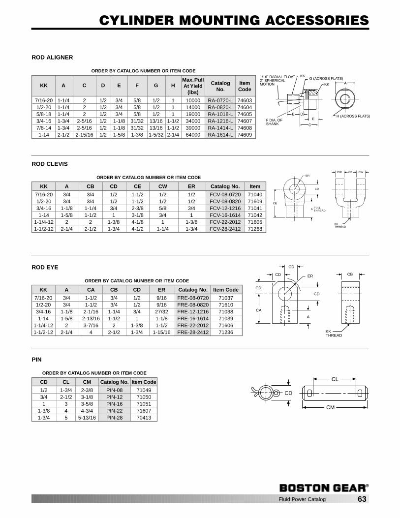
E D
F DIA. OFSHANK
E
C
G (ACROSS FLATS)
KK
KK1/16" RADIAL FLOAT2° SPHERICALMOTION A
H (ACROSS FLATS)
Fluid Power Catalog 63
CYLINDER MOUNTING ACCESSORIES
ORDER BY CATALOG NUMBER OR ITEM CODE
Max.PullCatalog Item KK A C D E F G H At Yield
No. Code(lbs)
7/16-20 1-1/4 2 1/2 3/4 5/8 1/2 1 10000 RA-0720-L 746031/2-20 1-1/4 2 1/2 3/4 5/8 1/2 1 14000 RA-0820-L 746045/8-18 1-1/4 2 1/2 3/4 5/8 1/2 1 19000 RA-1018-L 746053/4-16 1-3/4 2-5/16 1/2 1-1/8 31/32 13/16 1-1/2 34000 RA-1216-L 746077/8-14 1-3/4 2-5/16 1/2 1-1/8 31/32 13/16 1-1/2 39000 RA-1414-L 746081-14 2-1/2 2-15/16 1/2 1-5/8 1-3/8 1-5/32 2-1/4 64000 RA-1614-L 74609
ROD ALIGNER
ORDER BY CATALOG NUMBER OR ITEM CODE
KK A CB CD CE CW ER Catalog No. Item
7/16-20 3/4 3/4 1/2 1-1/2 1/2 1/2 FCV-08-0720 710401/2-20 3/4 3/4 1/2 1-1/2 1/2 1/2 FCV-08-0820 716093/4-16 1-1/8 1-1/4 3/4 2-3/8 5/8 3/4 FCV-12-1216 710411-14 1-5/8 1-1/2 1 3-1/8 3/4 1 FCV-16-1614 71042
1-1/4-12 2 2 1-3/8 4-1/8 1 1-3/8 FCV-22-2012 716051-1/2-12 2-1/4 2-1/2 1-3/4 4-1/2 1-1/4 1-3/4 FCV-28-2412 71268
ROD CLEVIS
ER
CD
CE
FULLTHREADA
KKTHREAD
CW CB CW
ORDER BY CATALOG NUMBER OR ITEM CODE
KK A CA CB CD ER Catalog No. Item Code
7/16-20 3/4 1-1/2 3/4 1/2 9/16 FRE-08-0720 710371/2-20 3/4 1-1/2 3/4 1/2 9/16 FRE-08-0820 716103/4-16 1-1/8 2-1/16 1-1/4 3/4 27/32 FRE-12-1216 710381-14 1-5/8 2-13/16 1-1/2 1 1-1/8 FRE-16-1614 71039
1-1/4-12 2 3-7/16 2 1-3/8 1-1/2 FRE-22-2012 716061-1/2-12 2-1/4 4 2-1/2 1-3/4 1-15/16 FRE-28-2412 71236
ROD EYE CD
CD
CD
CD
CA
ER
A
CB
KKTHREAD
ORDER BY CATALOG NUMBER OR ITEM CODE
CD CL CM Catalog No. Item Code
1/2 1-3/4 2-3/8 PIN-08 710493/4 2-1/2 3-1/8 PIN-12 710501 3 3-5/8 PIN-16 71051
1-3/8 4 4-3/4 PIN-22 716071-3/4 5 5-13/16 PIN-28 70413
PIN
CL
CM
CD

Fluid Power Catalog 65
DIRECTIONAL CONTROL VALVES
PageEK SERIES. . . . . . . . . . . . . . . . . . . . . . . . . . . . . . . . . . . . . . . . . . . . . . . 66-82
SOLENOID OPERATORS . . . . . . . . . . . . . . . . . . . . . . . . . . . . . . . . 70-71AIR OPERATORS . . . . . . . . . . . . . . . . . . . . . . . . . . . . . . . . . . . . . . 72-73MANUAL OPERATORS . . . . . . . . . . . . . . . . . . . . . . . . . . . . . . . . . 74-79MECHANICAL OPERATORS . . . . . . . . . . . . . . . . . . . . . . . . . . . . . 80-81REPAIR PARTS . . . . . . . . . . . . . . . . . . . . . . . . . . . . . . . . . . . . . . . . . . 68
AIR VALVE SIZING. . . . . . . . . . . . . . . . . . . . . . . . . . . . . . . . . . . . . . . . . 82-83
SERIES
EK1/4, 3/8 & 1/2 PTF
3 Way / 2 Position4 Way / 2 Position4 Way / 3 Position
Solenoid, Air,Manual,
MechanicalInline Spool 1.4–1.7
PORTS FUNCTIONS
VALVE SELECTION CHART
OPERATORS BODY TYPE CVRANGE
TABLE OF CONTENTS
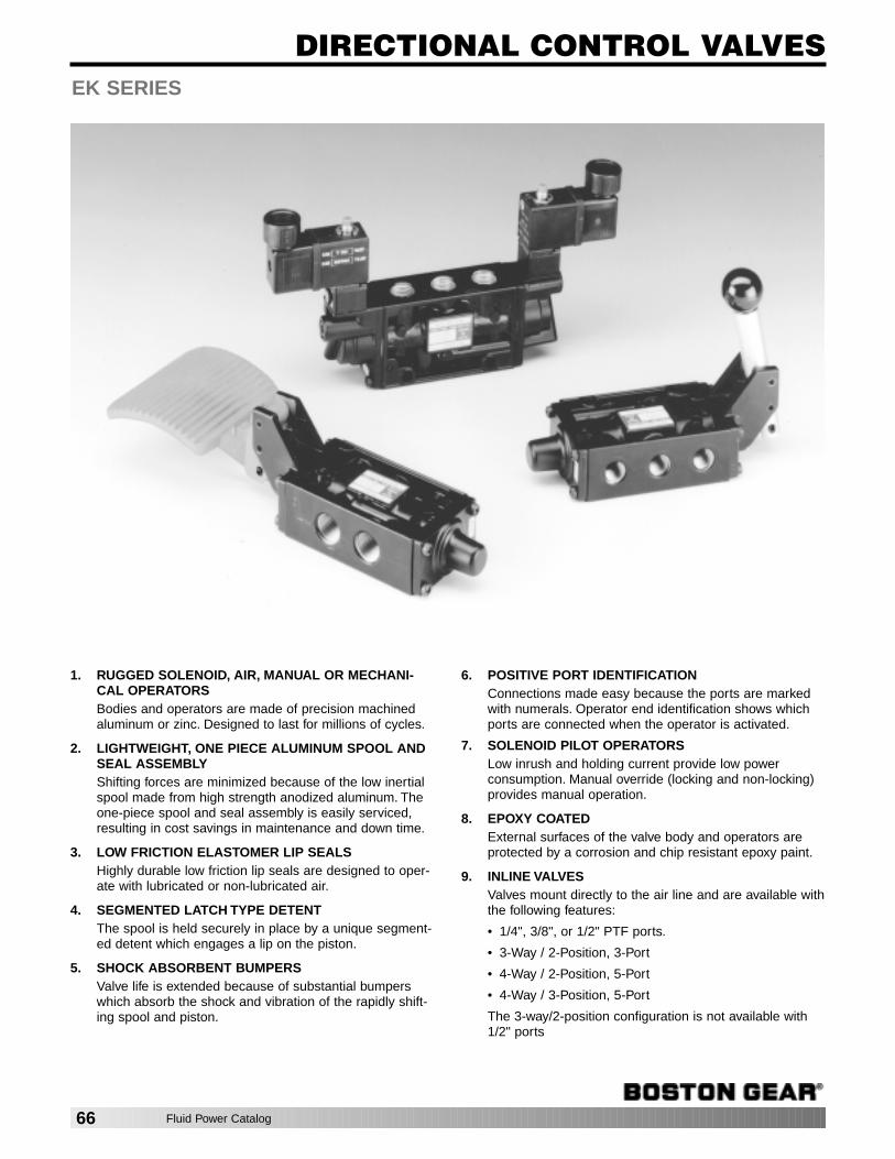
DIRECTIONAL CONTROL VALVESEK SERIES
1. RUGGED SOLENOID, AIR, MANUAL OR MECHANI-CAL OPERATORSBodies and operators are made of precision machinedaluminum or zinc. Designed to last for millions of cycles.
2. LIGHTWEIGHT, ONE PIECE ALUMINUM SPOOL ANDSEAL ASSEMBLYShifting forces are minimized because of the low inertialspool made from high strength anodized aluminum. Theone-piece spool and seal assembly is easily serviced,resulting in cost savings in maintenance and down time.
3. LOW FRICTION ELASTOMER LIP SEALSHighly durable low friction lip seals are designed to oper-ate with lubricated or non-lubricated air.
4. SEGMENTED LATCH TYPE DETENTThe spool is held securely in place by a unique segment-ed detent which engages a lip on the piston.
5. SHOCK ABSORBENT BUMPERSValve life is extended because of substantial bumperswhich absorb the shock and vibration of the rapidly shift-ing spool and piston.
6. POSITIVE PORT IDENTIFICATIONConnections made easy because the ports are markedwith numerals. Operator end identification shows whichports are connected when the operator is activated.
7. SOLENOID PILOT OPERATORSLow inrush and holding current provide low powerconsumption. Manual override (locking and non-locking)provides manual operation.
8. EPOXY COATEDExternal surfaces of the valve body and operators areprotected by a corrosion and chip resistant epoxy paint.
9. INLINE VALVESValves mount directly to the air line and are available withthe following features:
• 1/4", 3/8", or 1/2" PTF ports.
• 3-Way / 2-Position, 3-Port
• 4-Way / 2-Position, 5-Port
• 4-Way / 3-Position, 5-Port
The 3-way/2-position configuration is not available with1/2" ports
66 Fluid Power Catalog

DIRECTIONAL CONTROL VALVES
SpecificationsFluids: Filtered and lubricated or non-lubricated compressed
air or air at vacuum pressures.
Inlet Pressure Range:
Solenoid Operated Valves:
With Internal Pilot Supply: 15 to 150 PSIG*With External Pilot Supply: 10" Hg vacuum to 150 PSIGAir, Manual, or Mechanical Operated Valves: 10" Hg
vacuum to 150 PSIG*
Temperature Range (Ambient/Inlet):
Solenoid Operated Valves: –20° to 120°F** Air, Manual & Mechanical Operated Valves:
–20° to 160°F** Operator Pilot Pressures:
Maximum Pilot Pressure: 150 PSIG
Minimum Pilot Pressure at 150 PSIG.Main valve inlet pressures are given in the following table:
*Minimum Inlet Pressure is dependent on the type of operatorand return used. See Operator Pilot Pressure specificationsin Operating Specifications.
**With the dewpoint of supply air less than air temperaturebelow 35°F.
Air Operator Signal Duration: Air operated 2-position detent-ed or non-detented valves can be shifted with a momentary airsignal. Minimum signal duration is 17 milliseconds.
Valve MaterialsBody: AluminumSpool: Anodized aluminumElastomers: Nitrile and special nitrile-based low frictionelastomers.Solenoid Operator Base: PPS PlasticSolenoid Operator Plunger and Spring: Stainless steel
Seal Compatibility
EK Series Valve seals are compatible with the followinglubricants:
DC BR-2+ grease (Dow Corning)DC44 grease (Dow Corning)Non-detergent mineral based oil such as Mobil DTE light oil
EK seals are not compatible with WD-40 or commonly usedde-icer fluids. Consult factory to verify compatibility of lubri-cants or fluids not listed above.
*Flow Rating determined in accordance with NFPA/T3.21.3,Pneumatic fluid power—Flow test procedure and reportingmethod—For fixed orifice components.
WARNINGWhen a solenoid or air operator is used as a return for amanual or mechanical operator, the pilot pressure applied tothe return operator must not exceed 40 PSIG. Pilot pressuresgreater than 40 PSIG for a solenoid or air return will causestructural damage to the manual or mechanical operator andcan also result in injury to the user. If the available pilot pres-sure exceeds 40 PSIG, an external pilot supply only must beused and a restrictor, part number E54872-02 (73045), mustbe installed in the pilot port of the return operator to reducethe return force to an acceptable level. Pilot pressure to therestrictor must not exceed 150 PSIG.
E54872-02
Port Size PTF Standard
Inline Valves: 1/4", 3/8", or 1/2". Valves with 1/2" ports are notavailable in the 3-way/2-position configuration.
Minimum Pilot Pressure
SpringOperator Return Non-Detent Detented Centered
PSIG PSIG PSIG
Air Air 15 25 45 Solenoid Solenoid 15 25 45 Air Spring 35 — —Solenoid Spring 35 — —
Minimum Operating Forces — Manual & Mech. Operators
Force toOperator OperateNumber Description lbs.
KB0 Palm Button—Spring Return 18.0KB3 Palm Button — Detent 9.0KK0 Knob — Spring Return 18.0KK1 Knob — Detent 9.0KL0 Lever — Spring Return 9.0KL1 Lever — Detent, 2-Position 7.0KL2 Lever — Spring Centered 7.0KL3 Lever — Detent, 3-Position 7.0KT0 Treadle — Spring Return 13.0KT1 Treadle — Detent, 2-Position 9.0KT2 Treadle — Spring Centered 9.0KP0 Tappet — Spring Return 18.0KF0 Foot Pedal — Spring Return 11.0KR2 Lever Roller — Spring Return 11.0KR5 One-Way Trip Roller—Spring Return 11.0
EK SERIES
Average Flow Factors (Cv)*
Flow PathPort Port
Port 1 to 2 2 to 3Valve Size 1 to 4 4 to 5
3-Way Inline 1/4" 1.6 1.73/8" 1.6 1.7
4-Way, Inline 1/4" 1.6 1.73/8" 1.6 1.71/2" 1.6 1.7
9/16" HEX
1/8 – 27 PTF
.81
1/8 – 27 PTF
.33
Fluid Power Catalog 67
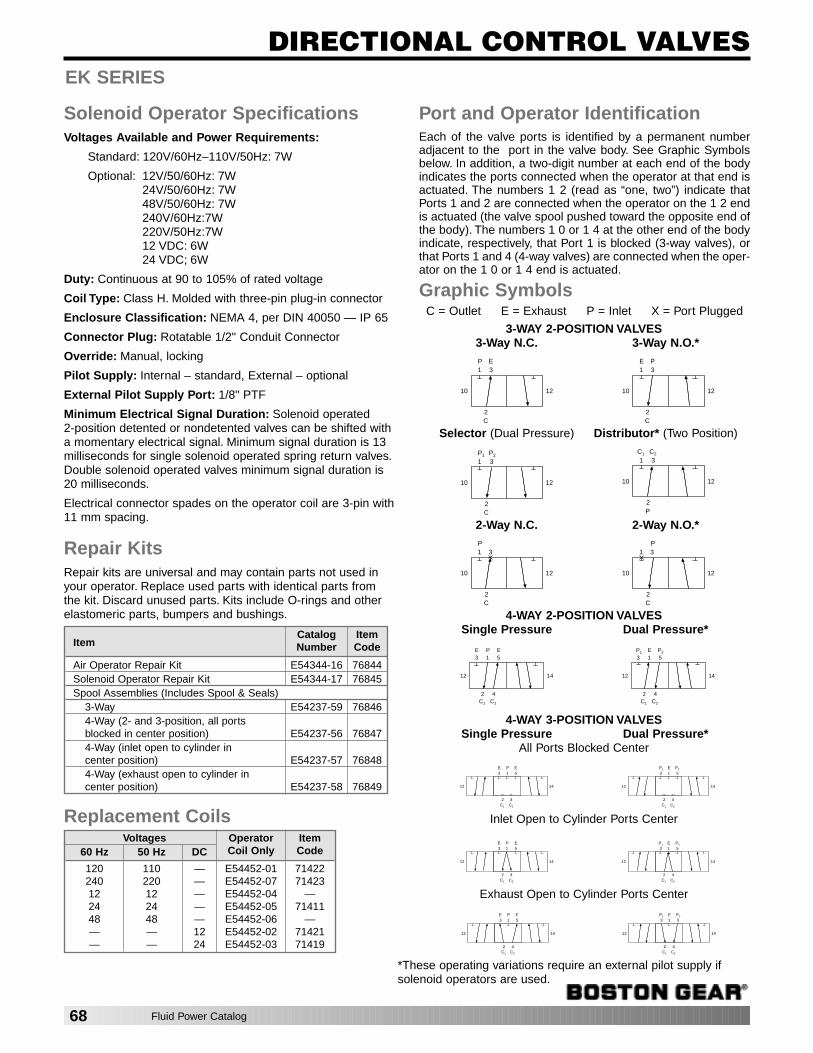
DIRECTIONAL CONTROL VALVES
Solenoid Operator SpecificationsVoltages Available and Power Requirements:
Standard: 120V/60Hz–110V/50Hz: 7W
Optional: 12V/50/60Hz: 7W24V/50/60Hz: 7W48V/50/60Hz: 7W240V/60Hz:7W220V/50Hz:7W12 VDC: 6W24 VDC; 6W
Duty: Continuous at 90 to 105% of rated voltage
Coil Type: Class H. Molded with three-pin plug-in connector
Enclosure Classification: NEMA 4, per DIN 40050 — IP 65
Connector Plug: Rotatable 1/2" Conduit Connector
Override: Manual, locking
Pilot Supply: Internal – standard, External – optional
External Pilot Supply Port: 1/8" PTF
Minimum Electrical Signal Duration: Solenoid operated 2-position detented or nondetented valves can be shifted witha momentary electrical signal. Minimum signal duration is 13milliseconds for single solenoid operated spring return valves.Double solenoid operated valves minimum signal duration is20 milliseconds.
Electrical connector spades on the operator coil are 3-pin with11 mm spacing.
Repair KitsRepair kits are universal and may contain parts not used inyour operator. Replace used parts with identical parts fromthe kit. Discard unused parts. Kits include O-rings and otherelastomeric parts, bumpers and bushings.
Replacement Coils
Port and Operator IdentificationEach of the valve ports is identified by a permanent numberadjacent to the port in the valve body. See Graphic Symbolsbelow. In addition, a two-digit number at each end of the bodyindicates the ports connected when the operator at that end isactuated. The numbers 1 2 (read as “one, two”) indicate thatPorts 1 and 2 are connected when the operator on the 1 2 endis actuated (the valve spool pushed toward the opposite end ofthe body). The numbers 1 0 or 1 4 at the other end of the bodyindicate, respectively, that Port 1 is blocked (3-way valves), orthat Ports 1 and 4 (4-way valves) are connected when the oper-ator on the 1 0 or 1 4 end is actuated.
Graphic SymbolsC = Outlet E = Exhaust P = Inlet X = Port Plugged
Voltages Operator Item60 Hz 50 Hz DC Coil Only Code
120 110 — E54452-01 71422240 220 — E54452-07 7142312 12 — E54452-04 —24 24 — E54452-05 7141148 48 — E54452-06 —— — 12 E54452-02 71421— — 24 E54452-03 71419
1 3
10
2C
12
P E1 3
10
2C
12
E P
1 3
10
2C
12
P1 P21 3
10
2P
12
C1 C2
1 3
10
2C
12
P1 3
10
2C
12
P
13
12
2C1
14
PE5E
4C2
13
12
2C1
14
EP1
5P2
4C2
13
12
2C1
14
PE5E
4C2
13
12
2C1
14
EP1
5P2
4C2
13
12
2C1
14
PE5E
4C2
13
12
2C1
14
EP1
5P2
4C2
*These operating variations require an external pilot supply ifsolenoid operators are used.
EK SERIES
13
12
2C1
14
PE5E
4C2
13
12
2C1
14
EP1
5P2
4C2
Exhaust Open to Cylinder Ports Center
Inlet Open to Cylinder Ports Center
4-WAY 3-POSITION VALVESSingle Pressure Dual Pressure*
All Ports Blocked Center
4-WAY 2-POSITION VALVESSingle Pressure Dual Pressure*
2-Way N.C. 2-Way N.O.*
Selector (Dual Pressure) Distributor* (Two Position)
3-WAY 2-POSITION VALVES3-Way N.C. 3-Way N.O.*
ItemCatalog ItemNumber Code
Air Operator Repair Kit E54344-16 76844Solenoid Operator Repair Kit E54344-17 76845Spool Assemblies (Includes Spool & Seals)
3-Way E54237-59 768464-Way (2- and 3-position, all ports blocked in center position) E54237-56 768474-Way (inlet open to cylinder in center position) E54237-57 768484-Way (exhaust open to cylinder in center position) E54237-58 76849
68 Fluid Power Catalog
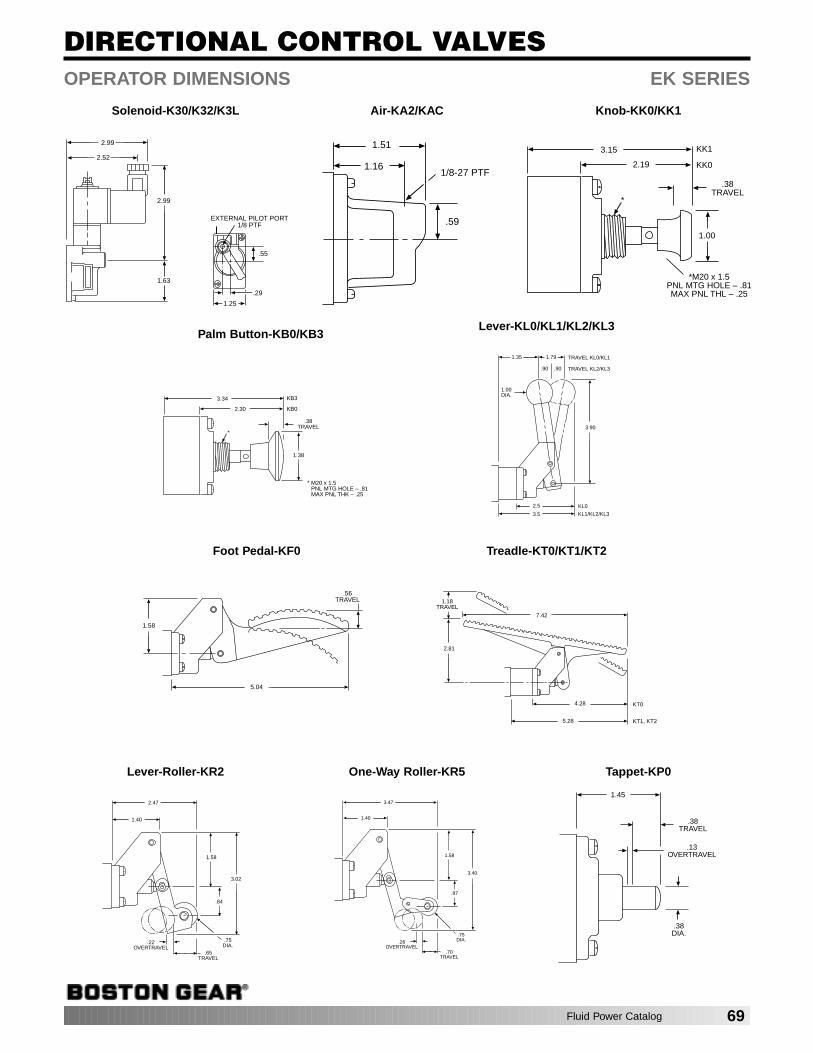
DIRECTIONAL CONTROL VALVESOPERATOR DIMENSIONS EK SERIES
Solenoid-K30/K32/K3L
.29
.55
1.25
EXTERNAL PILOT PORT1/8 PTF
1.63
2.99
2.99
2.52
Air-KA2/KAC
1.51
.59
1/8-27 PTF1.16
Knob-KK0/KK1
2.19
3.15 KK1
KK0
1.00
.38TRAVEL
*
*M20 x 1.5PNL MTG HOLE – .81MAX PNL THL – .25
Palm Button-KB0/KB3
2.30
3.34 KB3
KB0
1.38
.38TRAVEL
*
M20 x 1.5PNL MTG HOLE – .81MAX PNL THK – .25
*
Foot Pedal-KF0
1.58
.56TRAVEL
5.04
Treadle-KT0/KT1/KT2
7.42
2.81
4.28
1.18TRAVEL
KT0
5.28 KT1, KT2
Lever-KL0/KL1/KL2/KL3
1.79
3.90
3.5
KL0
1.35
1.00DIA.
.90.90
2.5
KL1/KL2/KL3
TRAVEL KL0/KL1
TRAVEL KL2/KL3
Lever-Roller-KR2
1.40
.84
2.47
3.02
.75 DIA.
.65TRAVEL
.22OVERTRAVEL
1.58
One-Way Roller-KR5
1.40
.87
3.47
3.40
.75DIA.
.70TRAVEL
.26OVERTRAVEL
1.58
Tappet-KP0
1.45
.38TRAVEL
.13OVERTRAVEL
.38DIA.
Fluid Power Catalog 69
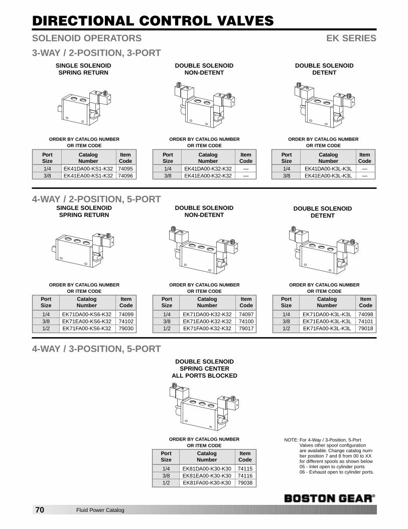
DIRECTIONAL CONTROL VALVES
DOUBLE SOLENOIDNON-DETENT
DOUBLE SOLENOIDDETENT
ORDER BY CATALOG NUMBER OR ITEM CODE
Port Catalog ItemSize Number Code1/4 EK41DA00-K32-K32 —3/8 EK41EA00-K32-K32 —
ORDER BY CATALOG NUMBER OR ITEM CODE
Port Catalog ItemSize Number Code1/4 EK41DA00-K3L-K3L —3/8 EK41EA00-K3L-K3L —
ORDER BY CATALOG NUMBER OR ITEM CODE
Port Catalog ItemSize Number Code1/4 EK41DA00-KS1-K32 740953/8 EK41EA00-KS1-K32 74096
SOLENOID OPERATORS EK SERIES
3-WAY / 2-POSITION, 3-PORT
SINGLE SOLENOIDSPRING RETURN
DOUBLE SOLENOIDNON-DETENT
DOUBLE SOLENOIDSPRING CENTER
ALL PORTS BLOCKED
4-WAY / 2-POSITION, 5-PORT
SINGLE SOLENOIDSPRING RETURN
DOUBLE SOLENOIDDETENT
4-WAY / 3-POSITION, 5-PORT
ORDER BY CATALOG NUMBER OR ITEM CODE
Port Catalog ItemSize Number Code
1/4 EK71DA00-KS6-K32 740993/8 EK71EA00-KS6-K32 741021/2 EK71FA00-KS6-K32 79030
ORDER BY CATALOG NUMBER OR ITEM CODE
Port Catalog ItemSize Number Code
1/4 EK71DA00-K32-K32 740973/8 EK71EA00-K32-K32 741001/2 EK71FA00-K32-K32 79017
ORDER BY CATALOG NUMBER OR ITEM CODE
Port Catalog ItemSize Number Code
1/4 EK81DA00-K30-K30 741153/8 EK81EA00-K30-K30 741161/2 EK81FA00-K30-K30 79038
ORDER BY CATALOG NUMBER OR ITEM CODE
Port Catalog ItemSize Number Code
1/4 EK71DA00-K3L-K3L 740983/8 EK71EA00-K3L-K3L 741011/2 EK71FA00-K3L-K3L 79018
NOTE: For 4-Way / 3-Position, 5-Port Valves other spool configuration are available. Change catalog num-ber position 7 and 8 from 00 to XXfor different spools as shown below05 - Inlet open to cylinder ports06 - Exhaust open to cylinder ports.
70 Fluid Power Catalog
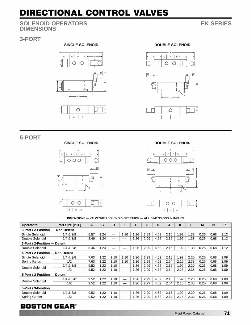
DIRECTIONAL CONTROL VALVES
E N P N G
A
K
H
LM
C C
F
J
SINGLE SOLENOID
G N P N G
A
K
H
LM
C C
F
DOUBLE SOLENOID
SOLENOID OPERATORS EK SERIESDIMENSIONS
3-PORT
E N P P N G
A
KH
LM
C D C
F
J
SINGLE SOLENOID
G N P P N G
A
KH
LM
C D C
F
DOUBLE SOLENOID5-PORT
DIMENSIONS — VALVE WITH SOLENOID OPERATOR — ALL DIMENSIONS IN INCHES
Operators Port Size (PTF) A C D E F G H J K L M N P
3-Port / 2-Position — Non-DetentSingle Solenoid 1/4 & 3/8 6.57 1.24 — 1.10 1.26 2.99 4.62 2.16 1.92 1.38 0.26 0.68 1.12Double Solenoid 1/4 & 3/8 8.46 1.24 — — 1.26 2.99 4.62 2.16 1.92 1.38 0.26 0.68 1.12
3-Port / 2-Position — DetentDouble Solenoid 1/4 & 3/8 8.46 1.24 — — 1.26 2.99 4.62 2.16 1.92 1.38 0.26 0.68 1.12
5-Port / 2-Position — Non-DetentSingle Solenoid 1/4 & 3/8 7.63 1.22 1.10 1.10 1.26 2.99 4.62 2.16 1.92 2.20 0.26 0.68 1.09Spring Return 1/2 7.63 1.22 1.10 1.10 1.26 2.99 4.62 2.64 2.16 2.38 0.26 0.68 1.09
Double Solenoid1/4 & 3/8 9.52 1.22 1.10 — 1.26 2.99 4.62 2.16 1.92 2.20 0.26 0.68 1.09
1/2 9.52 1.22 1.10 — 1.26 2.99 4.62 2.64 2.16 2.38 0.26 0.68 1.09
5-Port / 2-Position — Detent
Double Solenoid1/4 & 3/8 9.52 1.22 1.10 — 1.26 2.99 4.62 2.16 1.92 2.20 0.26 0.68 1.09
1/2 9.52 1.22 1.10 — 1.26 2.99 4.62 2.64 2.16 2.38 0.26 0.68 1.09
5-Port / 3-PositionDouble Solenoid 1/4 & 3/8 9.52 1.22 1.10 — 1.26 2.99 4.62 2.16 1.92 2.20 0.26 0.68 1.09Spring Center 1/2 9.52 1.22 1.10 — 1.26 2.99 4.62 2.64 2.16 2.38 0.26 0.68 1.09
Fluid Power Catalog 71

DIRECTIONAL CONTROL VALVES
SINGLE AIRSPRING RETURN
ORDER BY CATALOG NUMBER OR ITEM CODE
Port Catalog ItemSize* Number Code
1/4 EK71DA00-KS6-KA2 741843/8 EK71EA00-KS6-KA2 741851/2 EK71FA00-KS6-KA2 79032
ORDER BY CATALOG NUMBER OR ITEM CODE
Port Catalog ItemSize* Number Code
1/4 EK81DA00-KAC-KAC 741883/8 EK81EA00-KAC-KAC 741891/2 EK81FA00-KAC-KAC 79039
DOUBLE AIRNON-DETENT
DOUBLE AIR SPRING CENTER
ALL PORTS BLOCKED
4-WAY / 2-POSITION, 5-PORT
SINGLE AIRSPRING RETURN
DOUBLE AIRNON-DETENT
4-WAY / 3-POSITION, 5-PORT
AIR OPERATORS EK SERIES
3-WAY / 2-POSITION, 3-PORT
ORDER BY CATALOG NUMBER OR ITEM CODE
Port Catalog ItemSize* Number Code
1/4 EK41DA00-KS1-KA2 741803/8 EK41EA00-KS1-KA2 74181
ORDER BY CATALOG NUMBER OR ITEM CODE
Port Catalog ItemSize* Number Code
1/4 EK71DA00-KA2-KA2 742703/8 EK71EA00-KA2-KA2 745891/2 EK71FA00-KA2-KA2 79019
ORDER BY CATALOG NUMBER OR ITEM CODE
Port Catalog ItemSize* Number Code
1/4 EK41DA00-KA2-KA2 741823/8 EK41EA00-KA2-KA2 75351
NOTE: For 4-Way / 3-Position, 5-Port Valves other spool configuration areavailable. Change catalog numberposition 7 and 8 from 00 to XX fordifferent spools as shown below05 - Inlet open to cylinder ports06 - Exhaust open to cylinder ports.
*Port in Air Operator is tapped 1/8" PTF
*Port in Air Operator is tapped 1/8" PTF
*Port in Air Operator is tapped 1/8" PTF
*Port in Air Operator is tapped 1/8" PTF
*Port in Air Operator is tapped 1/8" PTF
72 Fluid Power Catalog
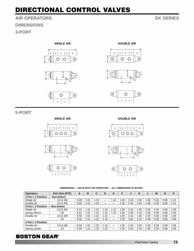
DIRECTIONAL CONTROL VALVES
E N P N B
A
K
LM
C C
J
F
SINGLE AIR
B N P N B
A
K
LM
C C
J
F
DOUBLE AIR
AIR OPERATORS EK SERIES
DIMENSIONS
3-PORT
E N P P N B
A
KJ
LM
C D C
F
SINGLE AIR
B N P P N B
A
KJ
LM
C D C
F
DOUBLE AIR
5-PORT
DIMENSIONS — VALVE WITH AIR OPERATOR — ALL DIMENSIONS IN INCHES
Operators Port Size (PTF) A B C D E F J K L M N P3 Port / 2 Position — Non-DetentSingle Air 1/4 & 3/8 5.09 1.51 1.24 — 1.10 1.26 2.16 1.92 1.38 0.26 0.68 1.12Double Air 1/4 & 3/8 5.50 1.51 1.24 — — 1.26 2.16 1.92 1.38 0.26 0.68 1.125 Port / 2 Position — Non-DetentSingle Air 1/4 & 3/8 6.15 1.51 1.22 1.10 1.10 1.26 2.16 1.92 2.20 0.26 0.68 1.09Spring Return 1/2 6.15 1.51 1.22 1.10 1.10 1.26 2.64 2.16 2.38 0.26 0.68 1.09Double Air 1/4 & 3/8 6.56 1.51 1.22 1.10 — 1.26 2.16 1.92 2.20 0.26 0.68 1.09
1/2 6.56 1.51 1.22 1.10 — 1.26 2.64 2.16 2.38 0.26 0.68 1.095 Port / 3 PositionDouble Air 1/4 & 3/8 6.56 1.51 1.22 1.10 — 1.26 2.16 1.92 2.20 0.26 0.68 1.09Spring Center 1/2 6.56 1.51 1.22 1.10 — 1.26 2.64 2.16 2.38 0.26 0.68 1.09
Fluid Power Catalog 73
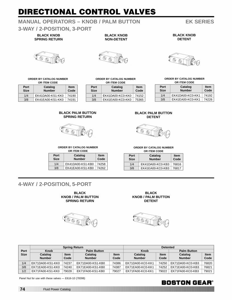
Spring Return DetentedPort Knob Palm Button Knob Palm ButtonSize Catalog Item Catalog Item Catalog Item Catalog Item
Number Code Number Code Number Code Number Code
1/4 EK71DA00-KS1-KK0 74237 EK71DA00-KS1-KB0 74386 EK71DA00-KC0-KK1 74250 EK71DA00-KC0-KB3 768203/8 EK71EA00-KS1-KK0 74240 EK71EA00-KS1-KB0 74387 EK71EA00-KC0-KK1 74252 EK71EA00-KC0-KB3 768211/2 EK71FA00-KS1-KK0 79028 EK71FA00-KS1-KB0 79027 EK71FA00-KC0-KK1 79022 EK71FA00-KC0-KB3 79021
DIRECTIONAL CONTROL VALVES
BLACKKNOB / PALM BUTTON
SPRING RETURN
BLACK KNOBNON-DETENT
BLACK KNOBDETENT
MANUAL OPERATORS – KNOB / PALM BUTTON EK SERIES3-WAY / 2-POSITION, 3-PORT
BLACK PALM BUTTONDETENT
BLACK PALM BUTTONSPRING RETURN
4-WAY / 2-POSITION, 5-PORT
BLACKKNOB / PALM BUTTON
DETENT
ORDER BY CATALOG NUMBER OR ITEM CODE
Port Catalog ItemSize Number Code
1/4 EK41DA00-KC0-KK0 741523/8 EK41EA00-KC0-KK0 75365
BLACK KNOBSPRING RETURN
ORDER BY CATALOG NUMBER OR ITEM CODE
Port Catalog ItemSize Number Code
1/4 EK41DA00-KS1-KK0 741903/8 EK41EA00-KS1-KK0 74191
ORDER BY CATALOG NUMBER OR ITEM CODE
Port Catalog ItemSize Number Code
1/4 EK41DA00-KC0-KK1 741923/8 EK41EA00-KC0-KK1 74226
ORDER BY CATALOG NUMBER OR ITEM CODE
Port Catalog ItemSize Number Code
1/4 EK41DA00-KS1-KB0 742583/8 EK41EA00-KS1-KB0 74262
ORDER BY CATALOG NUMBER OR ITEM CODE
Port Catalog ItemSize Number Code
1/4 EK41DA00-KC0-KB3 768163/8 EK41EA00-KC0-KB3 76817
Panel Nut for use with these valves — E616-10 (78398)
74 Fluid Power Catalog
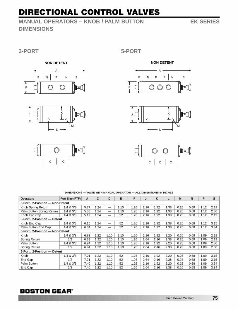
DIRECTIONAL CONTROL VALVES
E N P N S
A
K
LM
C C
J
F
NON DETENT
E N P P N S
A
KJ
LM
C D C
F
NON DETENT
MANUAL OPERATORS – KNOB / PALM BUTTON EK SERIESDIMENSIONS
3-PORT 5-PORT
DIMENSIONS — VALVE WITH MANUAL OPERATOR — ALL DIMENSIONS IN INCHES
Operators Port Size (PTF) A C D E F J K L M N P S3-Port / 2-Position — Non-DetentKnob Spring Return 1/4 & 3/8 5.77 1.24 — 1.10 1.26 2.16 1.92 1.38 0.26 0.68 1.12 2.19Palm Button Spring Return 1/4 & 3/8 5.88 1.24 — 1.10 1.26 2.16 1.92 1.38 0.26 0.68 1.12 2.30Knob End Cap 1/4 & 3/8 5.19 1.24 — .52 1.26 2.16 1.92 1.38 0.26 0.68 1.12 2.193-Port / 2-Position — DetentKnob End Cap 1/4 & 3/8 6.15 1.24 — .52 1.26 2.16 1.92 1.38 0.26 0.68 1.12 3.15Palm Button End Cap 1/4 & 3/8 6.34 1.24 — .52 1.26 2.16 1.92 1.38 0.26 0.68 1.12 3.345-Port / 2-Position — Non-DetentKnob 1/4 & 3/8 6.83 1.22 1.10 1.10 1.26 2.16 1.92 2.20 0.26 0.68 1.09 2.19Spring Return 1/2 6.83 1.22 1.10 1.10 1.26 2.64 2.16 2.38 0.26 0.68 1.09 2.19Palm Button 1/4 & 3/8 6.94 1.22 1.10 1.10 1.26 2.16 1.92 2.20 0.26 0.68 1.09 2.30Spring Return 1/2 6.94 1.22 1.10 1.10 1.26 2.64 2.16 2.38 0.26 0.68 1.09 2.305-Port / 2-Position — DetentKnob 1/4 & 3/8 7.21 1.22 1.10 .52 1.26 2.16 1.92 2.20 0.26 0.68 1.09 3.15End Cap 1/2 7.21 1.22 1.10 .52 1.26 2.64 2.16 2.38 0.26 0.68 1.09 3.15Palm Button 1/4 & 3/8 7.40 1.22 1.10 .52 1.26 2.16 1.92 2.20 0.26 0.68 1.09 3.34End Cap 1/2 7.40 1.22 1.10 .52 1.26 2.64 2.16 2.38 0.26 0.68 1.09 3.34
Fluid Power Catalog 75
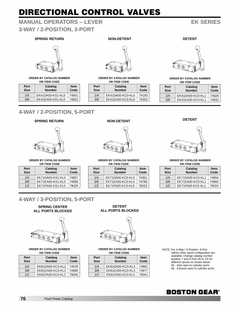
DIRECTIONAL CONTROL VALVES
SPRING RETURN
MANUAL OPERATORS – LEVER EK SERIES3-WAY / 2-POSITION, 3-PORT
NON-DETENT DETENT
DETENT
SPRING CENTERALL PORTS BLOCKED
DETENTALL PORTS BLOCKED
4-WAY / 2-POSITION, 5-PORT
SPRING RETURN NON-DETENT
4-WAY / 3-POSITION, 5-PORT
ORDER BY CATALOG NUMBER OR ITEM CODE
Port Catalog ItemSize Number Code
1/4 EK41DA00-KC0-KL0 741833/8 EK41EA00-KC0-KL0 75352
ORDER BY CATALOG NUMBER OR ITEM CODE
Port Catalog ItemSize Number Code
1/4 EK41DA00-KS1-KL0 748013/8 EK41EA00-KS1-KL0 74822
ORDER BY CATALOG NUMBER OR ITEM CODE
Port Catalog ItemSize Number Code
1/4 EK41DA00-KC0-KL1 748283/8 EK41EA00-KC0-KL1 74832
ORDER BY CATALOG NUMBER OR ITEM CODE
Port Catalog ItemSize Number Code
1/4 EK71DA00-KC0-KL1 748593/8 EK71EA00-KC0-KL1 748601/2 EK71FA00-KC0-KL1 79024
ORDER BY CATALOG NUMBER OR ITEM CODE
Port Catalog ItemSize Number Code
1/4 EK71DA00-KC0-KL0 743613/8 EK71EA00-KC0-KL0 747881/2 EK71FA00-KC0-KL0 79023
ORDER BY CATALOG NUMBER OR ITEM CODE
Port Catalog ItemSize Number Code
1/4 EK71DA00-KS1-KL0 748573/8 EK71EA00-KS1-KL0 748581/2 EK71FA00-KS1-KL0 79029
ORDER BY CATALOG NUMBER OR ITEM CODE
Port Catalog ItemSize Number Code
1/4 EK81DA00-KC0-KL3 748613/8 EK81EA00-KC0-KL3 749771/2 EK81FA00-KC0-KL3 79041
ORDER BY CATALOG NUMBER OR ITEM CODE
Port Catalog ItemSize Number Code
1/4 EK81DA00-KC0-KL2 749783/8 EK81EA00-KC0-KL2 749801/2 EK81FA00-KC0-KL2 79040
NOTE: For 4-Way / 3-Position, 5-Port Valves other spool configuration areavailable. Change catalog numberposition 7 and 8 from 00 to XX fordifferent spools as shown below05 - Inlet open to cylinder ports06 - Exhaust open to cylinder ports.
76 Fluid Power Catalog

DIRECTIONAL CONTROL VALVES
E N P N
A
K
LM
C C
J
F
V
U
SPRING RETURN
E N P N
A
K
LM
C C
J
F
V
U
END CAP
E N P P N
A
KJ
LM
C D C
V
U
F
SPRING RETURN
E N P P N
A
KJ
LM
C D C
V
U
F
END CAP5-PORT
MANUAL OPERATORS – LEVER EK SERIESDIMENSIONS3-PORT
DIMENSIONS — VALVE WITH MANUAL OPERATOR — ALL DIMENSIONS IN INCHES
Operators Port Size (PTF) A C D E F J K L M N P U V3-Port / 2-Position — Non-DetentSpring Return 1/4 & 3/8 6.08 1.24 — 1.10 1.26 2.16 1.92 1.38 0.26 0.68 1.12 2.50 4.53End Cap 1/4 & 3/8 5.50 1.24 — .52 1.26 2.16 1.92 1.38 0.26 0.68 1.12 2.50 4.533-Port / 2-Position — DetentEnd Cap 1/4 & 3/8 6.50 1.24 — .52 1.26 2.16 1.92 1.38 0.26 0.68 1.12 3.50 4.535-Port / 2-Position — Non-DetentSpring Return 1/4 & 3/8 7.14 1.22 1.10 1.10 1.26 2.16 1.92 2.20 0.26 0.68 1.09 2.50 4.53
1/2 7.14 1.22 1.10 1.10 1.26 2.64 2.16 2.38 0.26 0.68 1.09 2.50 4.53End Cap 1/4 & 3/8 6.56 1.22 1.10 .52 1.26 2.16 1.92 2.20 0.26 0.68 1.09 2.50 4.53
1/2 6.56 1.22 1.10 .52 1.26 2.64 2.16 2.38 0.26 0.68 1.09 2.50 4.535-Port / 2-Position — DetentEnd Cap 1/4 & 3/8 7.56 1.22 1.10 .52 1.26 2.16 1.92 2.20 0.26 0.68 1.09 3.50 4.53
1/2 7.56 1.22 1.10 .52 1.26 2.64 2.16 2.38 0.26 0.68 1.09 3.50 4.535-Port / 3-PositionSpring Center 1/4 & 3/8 8.56 1.22 1.10 1.52 1.26 2.16 1.92 2.20 0.26 0.68 1.09 3.50 4.53
1/2 8.56 1.22 1.10 1.52 1.26 2.64 2.16 2.38 0.26 0.68 1.09 3.50 4.53Detent 1/4 & 3/8 7.56 1.22 1.10 .52 1.26 2.16 1.92 2.20 0.26 0.68 1.09 3.50 4.53
1/2 7.56 1.22 1.10 .52 1.26 2.64 2.16 2.38 0.26 0.68 1.09 3.50 4.53
Fluid Power Catalog 77
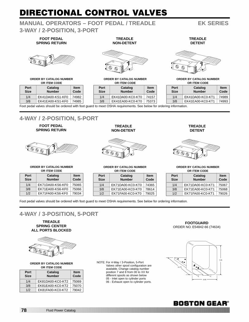
DIRECTIONAL CONTROL VALVES
FOOT PEDALSPRING RETURN
MANUAL OPERATORS – FOOT PEDAL / TREADLE EK SERIES
Foot pedal valves should be ordered with foot guard to meet OSHA requirements. See below for ordering information.
TREADLENON-DETENT
TREADLEDETENT
3-WAY / 2-POSITION, 3-PORT
TREADLENON-DETENT
TREADLEDETENT
TREADLESPRING CENTER
ALL PORTS BLOCKED
Foot pedal valves should be ordered with foot guard to meet OSHA requirements. See below for ordering information.
4-WAY / 2-POSITION, 5-PORT FOOT PEDAL
SPRING RETURN
FOOTGUARDORDER NO. E54842-66 (74634)
4-WAY / 3-POSITION, 5-PORT
7.29
6.00
14.75
ORDER BY CATALOG NUMBER OR ITEM CODE
Port Catalog ItemSize Number Code
1/4 EK71DA00-KC0-KT0 743653/8 EK71EA00-KC0-KT0 786141/2 EK71FA00-KC0-KT0 79025
ORDER BY CATALOG NUMBER OR ITEM CODE
Port Catalog ItemSize Number Code
1/4 EK71DA00-KC0-KT1 750673/8 EK71EA00-KC0-KT1 750681/2 EK71FA00-KC0-KT1 79026
ORDER BY CATALOG NUMBER OR ITEM CODE
Port Catalog ItemSize Number Code
1/4 EK71DA00-KS6-KF0 750653/8 EK71EA00-KS6-KF0 750661/2 EK71FA00-KS6-KF0 79034
ORDER BY CATALOG NUMBER OR ITEM CODE
Port Catalog ItemSize Number Code
1/4 EK81DA00-KC0-KT2 750693/8 EK81EA00-KC0-KT2 750701/2 EK81FA00-KC0-KT2 79042
ORDER BY CATALOG NUMBER OR ITEM CODE
Port Catalog ItemSize Number Code
1/4 EK41DA00-KS1-KF0 749823/8 EK41EA00-KS1-KF0 74985
ORDER BY CATALOG NUMBER OR ITEM CODE
Port Catalog ItemSize Number Code
1/4 EK41DA00-KC0-KT0 741573/8 EK41EA00-KC0-KT0 75373
ORDER BY CATALOG NUMBER OR ITEM CODE
Port Catalog ItemSize Number Code
1/4 EK41DA00-KC0-KT1 749893/8 EK41EA00-KC0-KT1 74993
NOTE: For 4-Way / 3-Position, 5-Port Valves other spool configuration areavailable. Change catalog numberposition 7 and 8 from 00 to XX fordifferent spools as shown below05 - Inlet open to cylinder ports06 - Exhaust open to cylinder ports.
78 Fluid Power Catalog
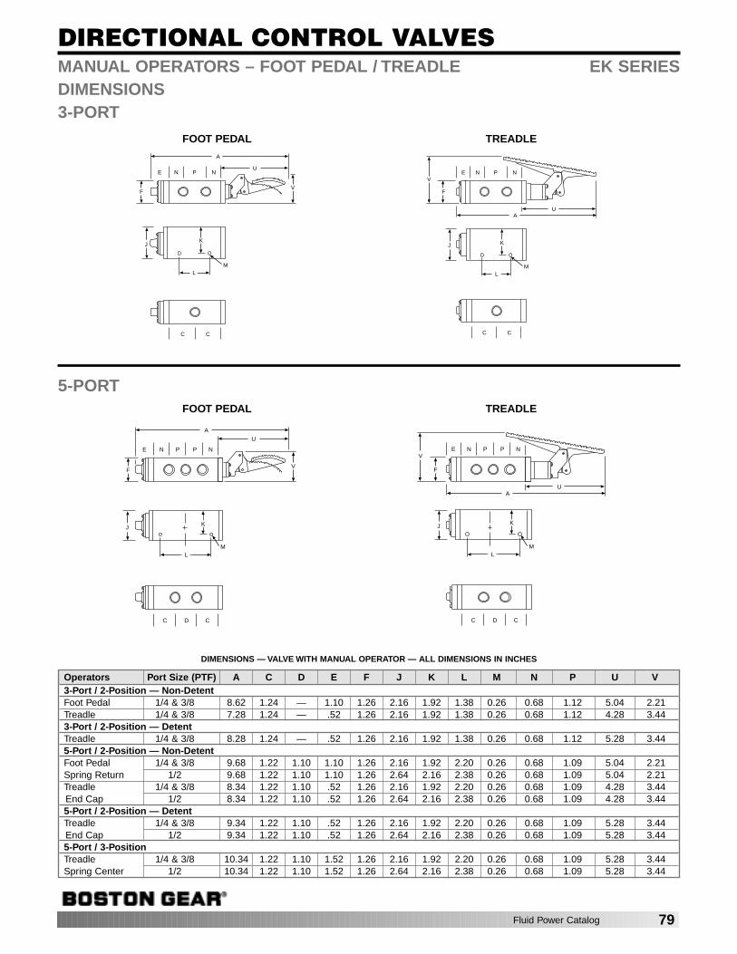
DIRECTIONAL CONTROL VALVES
E N P N
K
LM
C C
J
F
U
A
V
FOOT PEDAL
E N P N
K
LM
C C
J
F
UA
V
TREADLE
E N P P N
KJ
LM
C D C
F
U
A
V
FOOT PEDAL
E N P P N
KJ
LM
C D C
F
UA
V
TREADLE
5-PORT
MANUAL OPERATORS – FOOT PEDAL / TREADLE EK SERIESDIMENSIONS3-PORT
DIMENSIONS — VALVE WITH MANUAL OPERATOR — ALL DIMENSIONS IN INCHES
Operators Port Size (PTF) A C D E F J K L M N P U V3-Port / 2-Position — Non-DetentFoot Pedal 1/4 & 3/8 8.62 1.24 — 1.10 1.26 2.16 1.92 1.38 0.26 0.68 1.12 5.04 2.21Treadle 1/4 & 3/8 7.28 1.24 — .52 1.26 2.16 1.92 1.38 0.26 0.68 1.12 4.28 3.443-Port / 2-Position — DetentTreadle 1/4 & 3/8 8.28 1.24 — .52 1.26 2.16 1.92 1.38 0.26 0.68 1.12 5.28 3.445-Port / 2-Position — Non-DetentFoot Pedal 1/4 & 3/8 9.68 1.22 1.10 1.10 1.26 2.16 1.92 2.20 0.26 0.68 1.09 5.04 2.21Spring Return 1/2 9.68 1.22 1.10 1.10 1.26 2.64 2.16 2.38 0.26 0.68 1.09 5.04 2.21Treadle 1/4 & 3/8 8.34 1.22 1.10 .52 1.26 2.16 1.92 2.20 0.26 0.68 1.09 4.28 3.44End Cap 1/2 8.34 1.22 1.10 .52 1.26 2.64 2.16 2.38 0.26 0.68 1.09 4.28 3.445-Port / 2-Position — DetentTreadle 1/4 & 3/8 9.34 1.22 1.10 .52 1.26 2.16 1.92 2.20 0.26 0.68 1.09 5.28 3.44End Cap 1/2 9.34 1.22 1.10 .52 1.26 2.64 2.16 2.38 0.26 0.68 1.09 5.28 3.445-Port / 3-PositionTreadle 1/4 & 3/8 10.34 1.22 1.10 1.52 1.26 2.16 1.92 2.20 0.26 0.68 1.09 5.28 3.44Spring Center 1/2 10.34 1.22 1.10 1.52 1.26 2.64 2.16 2.38 0.26 0.68 1.09 5.28 3.44
Fluid Power Catalog 79
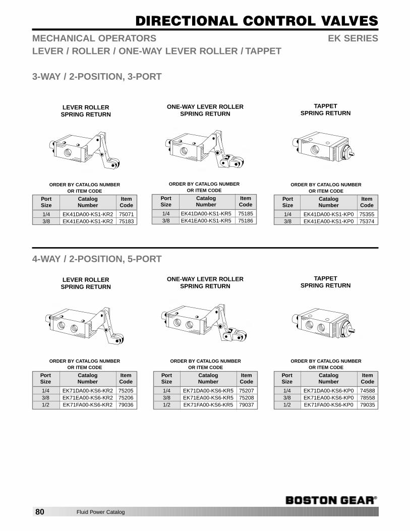
DIRECTIONAL CONTROL VALVES
ONE-WAY LEVER ROLLERSPRING RETURN
TAPPETSPRING RETURN
MECHANICAL OPERATORS EK SERIESLEVER / ROLLER / ONE-WAY LEVER ROLLER / TAPPET
3-WAY / 2-POSITION, 3-PORT
4-WAY / 2-POSITION, 5-PORT
ORDER BY CATALOG NUMBER OR ITEM CODE
Port Catalog ItemSize Number Code
1/4 EK41DA00-KS1-KR5 751853/8 EK41EA00-KS1-KR5 75186
LEVER ROLLERSPRING RETURN
ORDER BY CATALOG NUMBER OR ITEM CODE
Port Catalog ItemSize Number Code
1/4 EK41DA00-KS1-KR2 750713/8 EK41EA00-KS1-KR2 75183
ORDER BY CATALOG NUMBER OR ITEM CODE
Port Catalog ItemSize Number Code
1/4 EK41DA00-KS1-KP0 753553/8 EK41EA00-KS1-KP0 75374
ORDER BY CATALOG NUMBER OR ITEM CODE
Port Catalog ItemSize Number Code
1/4 EK71DA00-KS6-KR2 752053/8 EK71EA00-KS6-KR2 752061/2 EK71FA00-KS6-KR2 79036
ORDER BY CATALOG NUMBER OR ITEM CODE
Port Catalog ItemSize Number Code
1/4 EK71DA00-KS6-KR5 752073/8 EK71EA00-KS6-KR5 752081/2 EK71FA00-KS6-KR5 79037
ORDER BY CATALOG NUMBER OR ITEM CODE
Port Catalog ItemSize Number Code
1/4 EK71DA00-KS6-KP0 745883/8 EK71EA00-KS6-KP0 785581/2 EK71FA00-KS6-KP0 79035
ONE-WAY LEVER ROLLERSPRING RETURN
TAPPETSPRING RETURN
LEVER ROLLERSPRING RETURN
80 Fluid Power Catalog
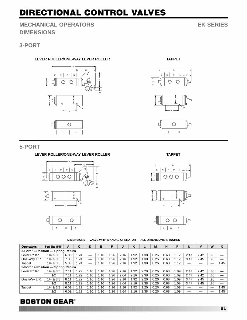
DIRECTIONAL CONTROL VALVES
E N P N
A
K
LM
C C
J
F
U
V
W
LEVER ROLLER/ONE-WAY LEVER ROLLER
E N P N
A
K
LM
C C
J
F
X
TAPPET
E N P P N
KJ
LM
C D C
F
A
U
V
W
LEVER ROLLER/ONE-WAY LEVER ROLLER
E N P P N
KJ
LM
C D C
F
A
X
TAPPET
5-PORT
MECHANICAL OPERATORS EK SERIESDIMENSIONS
3-PORT
DIMENSIONS — VALVE WITH MANUAL OPERATOR — ALL DIMENSIONS IN INCHES
Operators Port Size (PTF) A C D E F J K L M N P U V W X3-Port / 2-Position — Spring ReturnLever Roller 1/4 & 3/8 6.05 1.24 — 1.10 1.26 2.16 1.92 1.38 0.26 0.68 1.12 2.47 2.42 .60 —One-Way L.R. 1/4 & 3/8 7.05 1.24 — 1.10 1.26 2.16 1.92 1.38 0.26 0.68 1.12 3.47 2.45 .95 —Tappet 1/4 & 3/8 5.03 1.24 — 1.10 1.26 2.16 1.92 1.38 0.26 0.68 1.12 — — — 1.455-Port / 2-Position — Spring ReturnLever Roller 1/4 & 3/8 7.11 1.22 1.10 1.10 1.26 2.16 1.92 2.20 0.26 0.68 1.09 2.47 2.42 .60 —
1/2 7.11 1.22 1.10 1.10 1.26 2.64 2.16 2.38 0.26 0.68 1.09 2.47 2.42 .60 —One-Way L.R. 1/4 & 3/8 8.11 1.22 1.10 1.10 1.26 2.16 1.92 2.20 0.26 0.68 1.09 3.47 2.45 .95 —
1/2 8.11 1.22 1.10 1.10 1.26 2.64 2.16 2.38 0.26 0.68 1.09 3.47 2.45 .95 —Tappet 1/4 & 3/8 6.09 1.22 1.10 1.10 1.26 2.16 1.92 2.20 0.26 0.68 1.09 — — — 1.45
1/2 6.09 1.22 1.10 1.10 1.26 2.64 2.16 2.38 0.26 0.68 1.09 — — — 1.45
81

DIRECTIONAL CONTROL VALVESAIR VALVE SIZINGMost manufacturers catalogs give flow rating Cv for the valvewhich was established using NFPA standard T3.21.3. The following tables and formulas will enable you to quickly size a valve properly. The traditional, often used, approach ofusing the valve size equivalent to the port in the cylinder canbe very costly. Cylinder speed, not port size, should be thedetermining factor!
The following Cv calculations are based upon simplifiedformulas which yield results with acceptable accuracy underthe following standard condition:
Air at a temperature of 68°F
Absolute downstream or secondary pressure must be 53% ofabsolute inlet or primary pressure or greater. Below 53%, theair velocity may become sonic and the Cv formula does notapply. To calculate air flow to atmosphere, enter outlet pres-sure p2 as 53% of absolute inlet pressure p1. Pressure drop∆p would be 47% of absolute inlet pressure. These valveshave been calculated for a Cv = 1 in Table 3.
Nomenclature:B Pressure drop factorC Compression factorCv Flow factorD Cylinder Diameter (IN)F Cylinder Area (SQ IN)L Cylinder Stroke (IN)P1 Inlet or Primary Pressure (PSIG)P2 Outlet or Secondary Pressure (PSIG)∆p Pressure differential (p1 – p2) (PSID)q Air flow at actual condition (CFM)Q Air flow of free air (SCFM)t Time to complete one cylinder stroke (SEC)T Absolute temperature at operating pressure. (°R)
Deg R = Deg F + 460
VALVE SIZING FOR CYLINDER ACTUATION— DIRECTFORMULA
cylinder area(SQ IN) cylinder stroke compression factor
Cv= (see Table 1) F x (IN) L x (see Table 2) Cpressure drop time to complete
factor B x cylinder stroke t x 29(See Table 2) (SEC)
Example: Cylinder size 4" Dia. x 10" stroke.Time to extend: 2seconds. Inlet pressure 90 PSIG. Allowable pressure drop 5PSID. Determine Cv.
Solution: Table 1 F = 12.57 SQ IN.Table 2 C = 7.1
B = 21.612.57 x 10 x 7.1Cv =
21.6 x 2 x 29 =.7
Select a valve that has a Cv factor of .7 or higher. In mostcases a 1/4" valve would be sufficient. See Page 67 for Cv
ratings of Boston valves.It is considered good engineering practice to limit the pres-sure drop ∆p to approximately 10% of primary pressure p1.The smaller the allowable pressure drop, the larger therequired valve will become.
After the minimum required Cv has been calculated, the prop-er size valve can be selected from the catalog.
TABLE 1: CYLINDER PUSH BORE AREA F FOR COMMON SIZES OF CYLINDERS
*See page 74 for pull bore areas.
TABLE 2: COMPRESSION FACTOR C AND PRESSUREDROP FACTOR B.
Bore Size Push Bore*D (In.) F (Sq. In.)
7/16 .159/16 .253/4 .44
1-1/16 .891-1/4 1.231-1/2 1.77
2 3.14
Bore Size Push Bore*D (In.) F (Sq. In.)
2-1/2 4.913-1/4 8.30
4 12.575 19.646 28.278 50.27
Inlet Compression Pressure Drop Factor BPressure Factor For Various Pressure Drops ∆p
(PSIG) C 2 PSID 5 PSID 10 PSID 15 PSID 20 PSID
10 1.7 6.520 2.4 7.8 11.830 3.0 8.9 13.6 18.040 3.7 9.9 15.3 20.5 23.650 4.4 10.8 16.7 22.6 26.4 29.060 5.1 11.7 18.1 24.6 29.0 32.070 5.8 12.5 19.3 26.5 31.3 34.880 6.4 13.2 20.5 28.2 33.5 37.490 7.1 13.9 21.6 29.8 35.5 39.9100 7.8 14.5 22.7 31.3 37.4 42.1110 8.5 15.2 23.7 32.8 39.3 44.3120 9.2 15.8 24.7 34.2 41.0 46.4130 9.8 16.4 25.6 35.5 42.7 48.4140 10.5 16.9 26.5 36.8 44.3 50.3150 11.2 17.5 27.4 38.1 45.9 52.1160 11.9 18.0 28.2 39.3 47.4 53.9170 12.6 18.5 29.0 40.5 48.9 55.6180 13.2 19.0 29.8 41.6 50.3 57.2190 13.9 19.5 30.6 42.7 51.7 58.9200 14.6 20.0 31.4 43.8 53.0 60.4210 15.3 20.4 32.1 44.9 54.3 62.0220 16.0 20.9 32.8 45.9 55.6 63.5230 16.7 21.3 33.5 46.9 56.8 64.9240 17.3 21.8 34.2 47.9 58.1 66.3250 18.0 22.2 34.9 48.9 59.3 67.7
82 Fluid Power Catalog
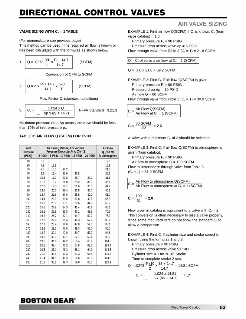
DIRECTIONAL CONTROL VALVESAIR VALVE SIZING
VALVE SIZING WITH CV = 1 TABLE
(For nomenclature see previous page)This method can be used if the required air flow is known orhas been calculated with the formulas as shown below.
1. Q = .0273 D2L x P2 + 14.7 (SCFM) t 14.7
Conversion of CFM to SCFM
2. Q = q x P2 + 14.7 x 528 (SCFM) 14.7 T
Flow Factor Cv (standard conditions)
3. Cv = 1.024 x Q NFPA Standard T3.21.3∆p x (p2 + 14.7)
Maximum pressure drop ∆p across the valve should be lessthan 10% of inlet pressure p1.
TABLE 3: AIR FLOW Q (SCFM) FOR Cv =1.
EXAMPLE 1: Find air flow Q(SCFM) if Cv is known. Cv (fromvalve catalog) = 1.8
Primary pressure P1 = 90 PSIGPressure drop across valve ∆p = 5 PSID
Flow through valve from Table 3 (Cv = 1) = 21.8 SCFM
Q = Cv of valve x air fiow at Cv = 1 (SCFM)
Q = 1.8 x 21.8 = 39.2 SCFM
EXAMPLE 2: Find Cv if air flow Q(SCFM) is given.Primary pressure P1 = 90 PSIGPressure drop ∆p = 10 PSIDAir flow Q = 60 SCFM
Flow through valve from Table 3 (Cv = 1) = 30.0 SCFM
Air Flow Q(SCFM)Cv = Air Flow at Cv = 1 (SCFM)
60 SCFMCv = 30 = 2.0
A valve with a minimum Cv of 2 should be selected.
EXAMPLE 3: Find Cv if air flow Q(SCFM) to atmosphere isgiven (from catalog).
Primary pressure P1 = 90 PSIGAir flow to atmosphere Q = 100 SCFM
Flow to atmosphere through valve from Table 3 (Cv = 1) = 51.0 SCFM
Air Flow to atmosphere Q(SCFM)Cv = Air Flow to atmosphere at Cv = 1 (SCFM)
100Cv =
51= 2.0
Flow given in catalog is equivalent to a valve with Cv = 2.This conversion is often necessary to size a valve properly,since some manufacturers do not show the standard Cv toallow a comparison.
EXAMPLE 4: Find Cv if cylinder size and stroke speed isknown using the formulas 1 and 3.
Primary pressure = 90 PSIGPressure drop across valve 5 PSIDCylinder size 4" DIA. x 10" StrokeTime to complete stroke 2 sec.
Q = .0273 4 2x10 x 85 + 14.7 = 14.81 SCFM2 14.7
Cv = 1.024 x 14.81 = .75 x (85 + 14.7)
Inlet Air Flow Q (SCFM) For Various Air FlowPressure Pressure Drops ∆p At A Cv=1 Q (SCFM)
(PSIG) 2 PSID 5 PSID 10 PSID 15 PSID 20 PSID To Atmosphere
10 6.7 12.020 7.9 11.9 16.930 9.0 13.8 18.2 21.840 9.9 15.4 20.6 23.8 26.650 10.8 16.9 22.8 26.7 29.2 31.560 11.6 18.2 24.8 29.2 32.3 36.470 12.3 19.5 26.7 31.6 35.1 41.280 13.0 20.7 28.4 33.8 37.7 46.190 13.7 21.8 30.0 35.8 40.2 51.0100 14.4 22.9 31.6 37.8 42.5 55.9110 15.0 23.9 33.1 39.6 44.7 60.7120 15.6 24.9 34.5 41.4 46.8 65.6130 16.1 25.8 35.8 43.1 48.8 70.5140 16.7 26.7 37.1 44.7 50.7 75.3150 17.2 27.6 38.4 46.3 52.5 80.2160 17.7 28.4 39.6 47.8 54.3 85.1170 18.2 29.3 40.8 49.3 56.0 90.0180 18.7 30.1 42.0 50.7 57.7 94.8190 19.2 30.9 43.1 52.1 59.4 99.7200 19.6 31.6 44.2 53.4 60.9 104.6210 20.1 32.4 45.2 54.8 62.5 109.4220 20.5 33.1 46.3 56.1 64.0 114.3230 21.0 33.8 47.3 57.3 65.5 119.2240 21.4 34.5 48.3 58.6 66.9 124.0250 21.8 35.2 49.3 59.8 68.3 128.9
=
=
Fluid Power Catalog 83
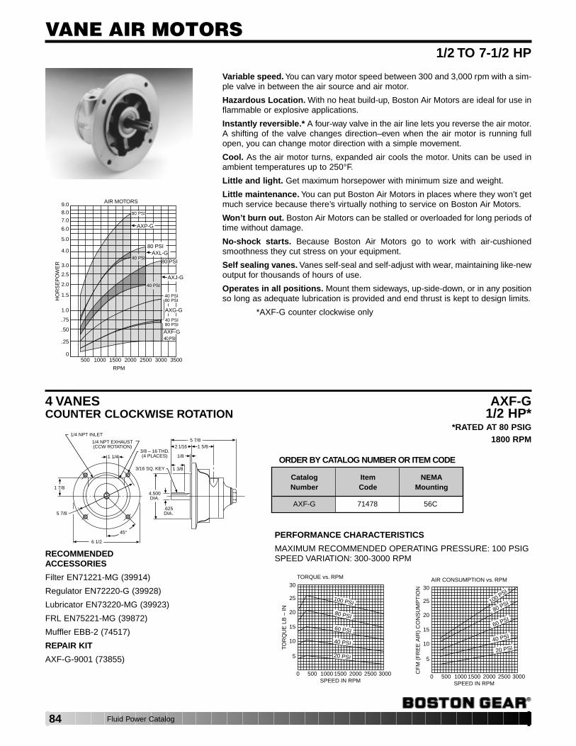
VANE AIR MOTORS 1/2 TO 7-1/2 HP
Variable speed. You can vary motor speed between 300 and 3,000 rpm with a sim-ple valve in between the air source and air motor.
Hazardous Location. With no heat build-up, Boston Air Motors are ideal for use inflammable or explosive applications.
Instantly reversible.* A four-way valve in the air line lets you reverse the air motor.A shifting of the valve changes direction–even when the air motor is running fullopen, you can change motor direction with a simple movement.
Cool. As the air motor turns, expanded air cools the motor. Units can be used inambient temperatures up to 250°F.
Little and light. Get maximum horsepower with minimum size and weight.
Little maintenance. You can put Boston Air Motors in places where they won’t getmuch service because there’s virtually nothing to service on Boston Air Motors.
Won’t burn out. Boston Air Motors can be stalled or overloaded for long periods oftime without damage.
No-shock starts. Because Boston Air Motors go to work with air-cushionedsmoothness they cut stress on your equipment.
Self sealing vanes. Vanes self-seal and self-adjust with wear, maintaining like-newoutput for thousands of hours of use.
Operates in all positions. Mount them sideways, up-side-down, or in any positionso long as adequate lubrication is provided and end thrust is kept to design limits.
*AXF-G counter clockwise only
AIR MOTORS
HO
RS
EP
OW
ER
RPM
9.0
8.0
7.0
6.0
5.0
4.0
3.0
2.5
2.0
1.5
1.0
.75
.50
.25
0500 1000 1500 2000 2500 3000 3500
80 PSI
AXP-G
80 PSIAXL-G
80 PSI40 PSI
AXJ-G40 PSI
40 PSI80 PSI
AXG-G
40 PSI80 PSI
AXF-G40 PSI
4 VANESCOUNTER CLOCKWISE ROTATION
AXF-G1/2 HP*
*RATED AT 80 PSIG1800 RPM
6 1/2
45°
5 7/8
1 1/4
4.500DIA.
3/16 SQ. KEY
.625DIA.
1 3/8
1/8
2 1/16 1 5/85 7/8
3/8 – 16 THD.(4 PLACES)
1/4 NPT EXHAUST(CCW ROTATION)
1/4 NPT INLET
1 7/8
RECOMMENDEDACCESSORIES
Filter EN71221-MG (39914)
Regulator EN72220-G (39928)
Lubricator EN73220-MG (39923)
FRL EN75221-MG (39872)
Muffler EBB-2 (74517)
REPAIR KIT
AXF-G-9001 (73855)
PERFORMANCE CHARACTERISTICS
MAXIMUM RECOMMENDED OPERATING PRESSURE: 100 PSIGSPEED VARIATION: 300-3000 RPM
ORDER BY CATALOG NUMBER OR ITEM CODE
0 500 1000 1500 2000 2500 3000SPEED IN RPM
TORQUE vs. RPM30
25
20
15
10
5
TOR
QU
E L
B –
IN
100 PSI
80 PSI
60 PSI
40 PSI
20 PSI
0 500 1000 1500 2000 2500 3000SPEED IN RPM
AIR CONSUMPTION vs. RPM30
25
20
15
10
5
CF
M (
FR
EE
AIR
) C
ON
SU
MP
TIO
N
100 PSI
80 PSI
60 PSI
40 PSI
20 PSI
CatalogNumber
AXF-G 71478 56C
ItemCode
NEMAMounting
84 Fluid Power Catalog

VANE AIR MOTORS
4 VANESREVERSIBLE
AXJ-G2HP*
*RATED AT 80 PSIG1800 RPM
45°
6 1/2
2 3/4
.625DIA.
3/16 SQ. KEY 1/82 1/16 3 1/8
8 5/16
1/2 NPT (2)
2 5/16
4.500
3/8 – 16 THD.(4) PLACES
5 7/8
RECOMMENDEDACCESSORIES
Filter EN61341-MG (70684)
Regulator EN62340-G (70690)
Lubricator EN63340-MG (70043)
FRL EN65341-MG (70620)
Muffler EBB-4 (74527)
REPAIR KIT
AXJ-G-9001 (73857)
PERFORMANCE CHARACTERISTICS
MAXIMUM RECOMMENDED OPERATING PRESSURE: 100 PSIGSPEED VARIATION: 300-3000 RPM
ORDER BY CATALOG NUMBER OR ITEM CODE
CatalogNumber
AXJ-G 70721 56C
ItemCode
NEMAMounting
4 VANESREVERSIBLE
AXG-G1HP*
*RATED AT 80 PSIG1800 RPM
6 1/2
45°
5 7/8
1 1/4
4.500DIA.
3/16 SQ. KEY
.625DIA.
1 3/8
1/8
2 1/16 2 1/166 11/16
3/8 – 16 THD.(4 PLACES)
1/4 NPT (2)
RECOMMENDEDACCESSORIES
Filter EN71221-MG (39914)
Regulator EN72220-G (39928)
Lubricator EN73220-MG (39923)
FRL EN75221-MG (39872)
Muffler EBB-2 (74517)
REPAIR KIT
AXG-G-9001 (73856)
PERFORMANCE CHARACTERISTICS
MAXIMUM RECOMMENDED OPERATING PRESSURE: 100 PSIGSPEED VARIATION: 300-3000 RPM
ORDER BY CATALOG NUMBER OR ITEM CODE
0 500 1000 1500 2000 2500 3000SPEED IN RPM
TORQUE vs. RPM60
50
40
30
20
10
TOR
QU
E L
B –
IN
100 PSI80 PSI
60 PSI
40 PSI
20 PSI
0 500 1000 1500 2000 2500 3000SPEED IN RPM
AIR CONSUMPTION vs. RPM80
70
60
50
40
CF
M (
FR
EE
AIR
) C
ON
SU
MP
TIO
N
100 PSI
80 PSI
60 PSI
40 PSI
20 PSI
30
20
10
0 500 1000 1500 2000 2500 3000SPEED IN RPM
TORQUE vs. RPM120
100
80
60
40
20
TOR
QU
E L
B –
IN
100 PSI80 PSI
60 PSI
40 PSI
20 PSI
0 500 1000 1500 2000 2500 3000SPEED IN RPM
AIR CONSUMPTION vs. RPM140
120
100
80
60
40
CF
M (
FR
EE
AIR
) C
ON
SU
MP
TIO
N
100 PSI
80 PSI
60 PSI
40 PSI
20 PSI
20
CatalogNumber
AXG-G 70720 56C
ItemCode
NEMAMounting
Fluid Power Catalog 85

VANE AIR MOTORS
6 VANESREVERSIBLE
AXP-G7 1⁄2 HP*
*RATED AT 80 PSIG1800 RPM
1/32 x 45°CHAM
6 5/8 2 3/4
.875DIA.
4.500
1 3/8
3/16 SQ.KEY
2 1/8 5 7/8
13 5/8
4 1/4
2 1/8
3/8 – 16 UNC-2BTAP THRU(4) HOLES
45°TYP
4
7 9/32
3 3/8
6 3/4
2 15/16 R
13/32(4) HOLES
8
1 1/4 NPT
RECOMMENDEDACCESSORIES
Filter EN41471-MG (73949)
Regulator EN42470-G (74906)
Lubricator EN43470-MG (73965)
FRL EN45471-MG (73897)
REPAIR KIT
AXP-G-9001 (73859)
PERFORMANCE CHARACTERISTICS
MAXIMUM RECOMMENDED OPERATING PRES-SURE: 100 PSIG SPEED VARIATION: 300-2000 RPM
ORDER BY CATALOG NUMBER OR ITEM CODE
CatalogNumber
AXP-G 71477 145TC
ItemCode
NEMAMounting
4 VANESREVERSIBLE
AXL-G4HP
*RATED AT 80 PSIG1800 RPM
45°
6 1/2
2 3/4
3/16 SQ. KEY1/8
2 1/8 3 27/329 1/2
1/2NPT (2)
2 17/32
4.500
3/8 – 16 THD.(4 PLACES)
5 7/8 BOLTCIRCLE
.875DIA.
1 3/8
RECOMMENDEDACCESSORIES
Filter EN61341-MG (70684)
Regulator EN62340-G (70690)
Lubricator EN63340-MG (70043)
FRL EN65341-MG (70620)
Muffler EBB-4 (74527)
REPAIR KIT
AXL-G-9001 (73858)
PERFORMANCE CHARACTERISTICS
MAXIMUM RECOMMENDED OPERATING PRESSURE: 100 PSIGSPEED VARIATION: 300-2500 RPM
ORDER BY CATALOG NUMBER OR ITEM CODE
CatalogNumber
AXL-G 70722 145TC
ItemCode
NEMAMounting
0 500 1000 1500 2000 2500SPEED IN RPM
TORQUE vs. RPM
180
160
140
120
100
80
TOR
QU
E L
B –
IN
100 PSI80 PSI
60 PSI
40 PSI
20 PSI
60
40
20
0 500 1000 1500 2000 2500SPEED IN RPM
AIR CONSUMPTION vs. RPM180
160
140
120
100
80
CF
M (
FR
EE
AIR
) C
ON
SU
MP
TIO
N
100 PSI
80 PSI
60 PSI
40 PSI
20 PSI60
40
20
0 500 1000 1500 2000SPEED IN RPM
TORQUE vs. RPM400
360
320
280
240
200
TOR
QU
E L
B –
IN
100 PSI
80 PSI
60 PSI
40 PSI
20 PSI
160
120
80
40
0 500 1000 1500 2000SPEED IN RPM
AIR CONSUMPTION vs. RPM280
240
200
160
120
80
CF
M (
FR
EE
AIR
) C
ON
SU
MP
TIO
N
100 PSI
80 PSI
60 PSI
40 PSI
20 PSI
40
86 Fluid Power Catalog
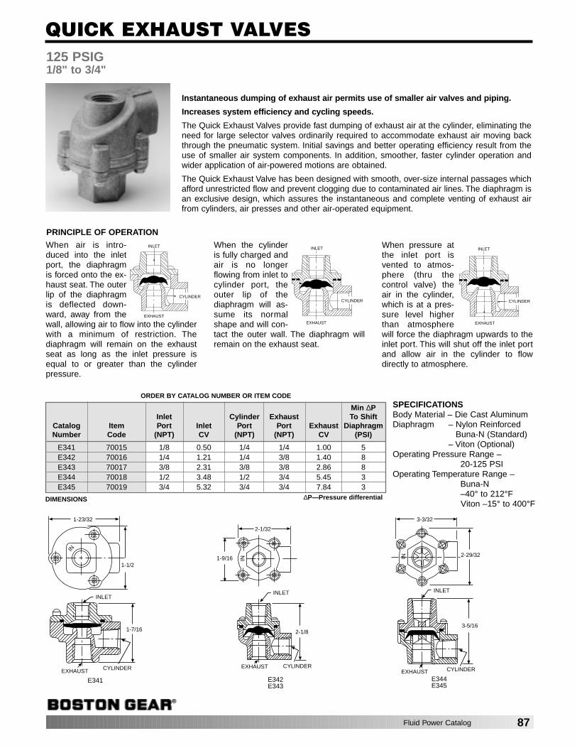
Fluid Power Catalog 87
125 PSIG1/8" to 3/4"
Instantaneous dumping of exhaust air permits use of smaller air valves and piping.
Increases system efficiency and cycling speeds.
The Quick Exhaust Valves provide fast dumping of exhaust air at the cylinder, eliminating theneed for large selector valves ordinarily required to accommodate exhaust air moving backthrough the pneumatic system. Initial savings and better operating efficiency result from theuse of smaller air system components. In addition, smoother, faster cylinder operation andwider application of air-powered motions are obtained.
The Quick Exhaust Valve has been designed with smooth, over-size internal passages whichafford unrestricted flow and prevent clogging due to contaminated air lines. The diaphragm isan exclusive design, which assures the instantaneous and complete venting of exhaust airfrom cylinders, air presses and other air-operated equipment.
PRINCIPLE OF OPERATION
When air is intro-duced into the inletport, the diaphragmis forced onto the ex-haust seat. The outerlip of the diaphragmis deflected down-ward, away from thewall, allowing air to flow into the cylinderwith a minimum of restriction. Thediaphragm will remain on the exhaustseat as long as the inlet pressure isequal to or greater than the cylinderpressure.
When the cylinder is fully charged andair is no longerflowing from inlet tocylinder port, theouter lip of thediaphragm will as-sume its normalshape and will con-tact the outer wall. The diaphragm willremain on the exhaust seat.
When pressure atthe inlet port isvented to atmos-phere (thru thecontrol valve) theair in the cylinder,which is at a pres-sure level higherthan atmospherewill force the diaphragm upwards to theinlet port. This will shut off the inlet portand allow air in the cylinder to flowdirectly to atmosphere.
QUICK EXHAUST VALVES
1-23/32
1-1/2
INLET
1-7/16
CYLINDEREXHAUST
E341
IN
2-1/32
1-9/16 IN
INLET
2-1/8
CYLINDEREXHAUST
E342E343
3-3/32
2-29/32
E344E345
IN
EXHAUST
INLET
3-5/16
CYLINDER
ORDER BY CATALOG NUMBER OR ITEM CODE
Min ∆PInlet Cylinder Exhaust To Shift
Catalog Item Port Inlet Port Port Exhaust DiaphragmNumber Code (NPT) CV (NPT) (NPT) CV (PSI)
E341 70015 1/8 0.50 1/4 1/4 1.00 5E342 70016 1/4 1.21 1/4 3/8 1.40 8E343 70017 3/8 2.31 3/8 3/8 2.86 8E344 70018 1/2 3.48 1/2 3/4 5.45 3E345 70019 3/4 5.32 3/4 3/4 7.84 3
SPECIFICATIONSBody Material – Die Cast AluminumDiaphragm – Nylon Reinforced
Buna-N (Standard)– Viton (Optional)
Operating Pressure Range – 20-125 PSI
Operating Temperature Range – Buna-N –40° to 212°FViton –15° to 400°F
CYLINDER
EXHAUST
INLET
CYLINDER
INLET
EXHAUST
CYLINDER
INLET
EXHAUST
DIMENSIONS ∆P—Pressure differential

2000 PSI (MAXIMUM)1/8" to 3/4" NPT
SPECIFICATIONS
Max. Operating Pressure – 2000 PSIOperating Temperature Range – –15° to +400°FStandard Cracking Pressure – 1 to 2.5 PSIMaterials:
Housing – BrassNeedle – BrassWasher – TeflonKnob – AluminumBall – Stainless SteelRetainer – Stainless SteelO-Ring – Viton
FLOW CONTROL VALVEwith Free Reverse
A spring biased ball provides full flow inone direction; a tapered stainless steelneedle provides a wide range of adjust-ment of flow in the controlled direction. Alocknut prevents unwanted changes inadjustment. An aluminum knurled knobis standard.
NEEDLE VALVE
A wide range of flow adjustment is pos-sible because of the fine threadedtapered needle. Unwanted changes inadjustment are prevented by a locknut.An aluminum knurled knob is standard.
CHECK VALVE
A slight pressure differential fully opensor closes the check valve. This valve issupplied standard with a ball check.
FLOW CONTROL, NEEDLE, CHECK VALVES
MAX. OPENE
L
G
D
CONTROLLED FLOW
MAX. OPEN
E
S
D
PREFERRED FLOW
G
S
D
FREE FLOW
ALL DIMENSIONS IN INCHES
Size D(NPTF) Hex E G L S
1/8 11/16 7/8 13/64 1-3/4 1-15/321/4 7/8 1 23/64 2-3/8 23/8 1-1/16 1-3/16 11/32 2-3/4 2-1/41/2 1-5/16 1-7/16 15/32 3-3/16 2-21/323/4 1-5/8 1-5/8 17/32 3-9/16 2-15/16
ORDER BY CATALOG NUMBER OR ITEM CODE
FLOW CONTROL VALVE NEEDLE VALVE CHECK VALVESize Catalog Item Flow Catalog Item Flow Catalog Item Flow
(NPTF) Number Code CV (GPM) Number Code CV (GPM) Number Code CV (GPM)
1/8 E311 70000 .23 1.5 E321 70005 .20 3.2 E331 70010 .23 1.51/4 E312 70001 .54 3.0 E322 70006 .43 7.0 E332 70011 .54 3.03/8 E313 70002 .83 5.0 E323 70007 .78 13.5 E333 70012 .83 5.01/2 E314 70003 1.47 8.0 E324 70008 1.24 22.5 E334 70013 1.47 8.03/4 E315 70004 1.90 12.0 E325 70009 1.93 34.0 E335 70014 1.90 12.0
88 Fluid Power Catalog
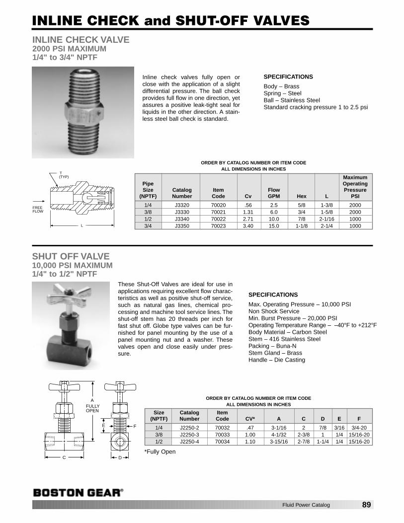
Fluid Power Catalog 89
INLINE CHECK VALVE2000 PSI MAXIMUM1/4" to 3/4" NPTF
Inline check valves fully open orclose with the application of a slightdifferential pressure. The ball checkprovides full flow in one direction, yetassures a positive leak-tight seal forliquids in the other direction. A stain-less steel ball check is standard.
SHUT OFF VALVE10,000 PSI MAXIMUM1/4" to 1/2" NPTF
These Shut-Off Valves are ideal for use inapplications requiring excellent flow charac-teristics as well as positive shut-off service,such as natural gas lines, chemical pro-cessing and machine tool service lines. Theshut-off stem has 20 threads per inch forfast shut off. Globe type valves can be fur-nished for panel mounting by the use of apanel mounting nut and a washer. Thesevalves open and close easily under pres-sure.
*Fully Open
INLINE CHECK and SHUT-OFF VALVES
SPECIFICATIONS
Body – BrassSpring – SteelBall – Stainless SteelStandard cracking pressure 1 to 2.5 psi
SPECIFICATIONS
Max. Operating Pressure – 10,000 PSINon Shock Service Min. Burst Pressure – 20,000 PSIOperating Temperature Range – –40°F to +212°FBody Material – Carbon SteelStem – 416 Stainless SteelPacking – Buna-NStem Gland – BrassHandle – Die Casting
T(TYP)
FREEFLOW
L
FE
D
AFULLYOPEN
C
ORDER BY CATALOG NUMBER OR ITEM CODEALL DIMENSIONS IN INCHES
MaximumPipe OperatingSize Catalog Item Flow Pressure
(NPTF) Number Code Cv GPM Hex L PSI
1/4 J3320 70020 .56 2.5 5/8 1-3/8 20003/8 J3330 70021 1.31 6.0 3/4 1-5/8 20001/2 J3340 70022 2.71 10.0 7/8 2-1/16 10003/4 J3350 70023 3.40 15.0 1-1/8 2-1/4 1000
ORDER BY CATALOG NUMBER OR ITEM CODEALL DIMENSIONS IN INCHES
Size Catalog Item(NPTF) Number Code CV* A C D E F
1/4 J2250-2 70032 .47 3-1/16 2 7/8 3/16 3/4-203/8 J2250-3 70033 1.00 4-1/32 2-3/8 1 1/4 15/16-201/2 J2250-4 70034 1.10 3-15/16 2-7/8 1-1/4 1/4 15/16-20
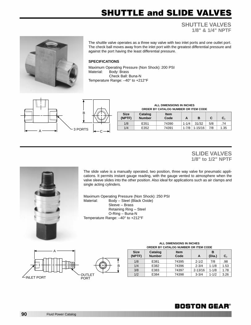
SHUTTLE VALVES1/8" & 1/4" NPTF
The shuttle valve operates as a three way valve with two inlet ports and one outlet port.The check ball moves away from the inlet port with the greatest differential pressure andagainst the port having the least differential pressure.
SPECIFICATIONS
Maximum Operating Pressure (Non Shock): 200 PSIMaterial: Body: Brass
Check Ball: Buna-NTemperature Range: –40° to +212°F
SLIDE VALVES1/8" to 1/2" NPTF
The slide valve is a manually operated, two position, three way valve for pneumatic appli-cations. It permits instant gauge reading, with the gauge vented to atmosphere when thevalve sleeve slides into the other position. Also ideal for applications such as air clamps andsingle acting cylinders.
Maximum Operating Pressure (Non Shock): 250 PSIMaterial: Body – Steel (Black Oxide)
Sleeve – BrassRetaining Ring – SteelO-Ring – Buna-N
Temperature Range: –40° to +212°F
SHUTTLE and SLIDE VALVES
ALL DIMENSIONS IN INCHESORDER BY CATALOG NUMBER OR ITEM CODE
Size Catalog Item(NPTF) Number Code A B C CV
1/8 E351 74390 1-1/4 31/32 5/8 .741/4 E352 74391 1-7/8 1-15/16 7/8 1.35
ALL DIMENSIONS IN INCHESORDER BY CATALOG NUMBER OR ITEM CODE
Size Catalog Item B(NPTF) Number Code A (Dia.) CV
1/8 E381 74395 2-1/2 7/8 .981/4 E382 74396 2-3/4 1-1/8 1.533/8 E383 74397 2-13/16 1-1/8 1.781/2 E384 74398 3-3/4 1-1/2 3.26
C
B
3 PORTSA
B
OUTLETPORT
A
INLET PORT
90 Fluid Power Catalog
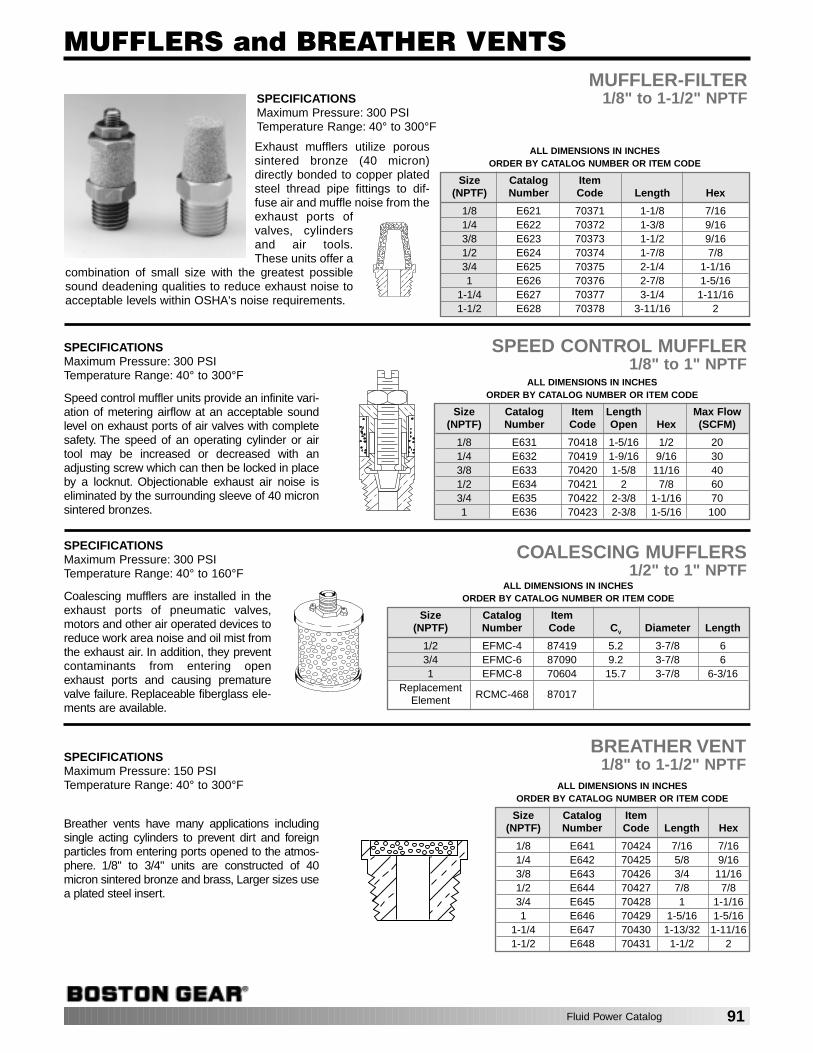
Fluid Power Catalog 91
MUFFLER-FILTER1/8" to 1-1/2" NPTF
Exhaust mufflers utilize poroussintered bronze (40 micron)directly bonded to copper platedsteel thread pipe fittings to dif-fuse air and muffle noise from theexhaust ports ofvalves, cylindersand air tools.These units offer a
combination of small size with the greatest possiblesound deadening qualities to reduce exhaust noise toacceptable levels within OSHA's noise requirements.
SPEED CONTROL MUFFLER1/8" to 1" NPTF
COALESCING MUFFLERS1/2" to 1" NPTF
MUFFLERS and BREATHER VENTS
ALL DIMENSIONS IN INCHESORDER BY CATALOG NUMBER OR ITEM CODE
Size Catalog Item Length Max Flow(NPTF) Number Code Open Hex (SCFM)
1/8 E631 70418 1-5/16 1/2 201/4 E632 70419 1-9/16 9/16 303/8 E633 70420 1-5/8 11/16 401/2 E634 70421 2 7/8 603/4 E635 70422 2-3/8 1-1/16 701 E636 70423 2-3/8 1-5/16 100
ALL DIMENSIONS IN INCHESORDER BY CATALOG NUMBER OR ITEM CODE
Size Catalog Item(NPTF) Number Code CV Diameter Length
1/2 EFMC-4 87419 5.2 3-7/8 63/4 EFMC-6 87090 9.2 3-7/8 61 EFMC-8 70604 15.7 3-7/8 6-3/16
ReplacementRCMC-468 87017Element
BREATHER VENT1/8" to 1-1/2" NPTF
Breather vents have many applications includingsingle acting cylinders to prevent dirt and foreignparticles from entering ports opened to the atmos-phere. 1/8" to 3/4" units are constructed of 40micron sintered bronze and brass, Larger sizes usea plated steel insert.
ALL DIMENSIONS IN INCHESORDER BY CATALOG NUMBER OR ITEM CODE
Size Catalog Item(NPTF) Number Code Length Hex
1/8 E641 70424 7/16 7/161/4 E642 70425 5/8 9/163/8 E643 70426 3/4 11/161/2 E644 70427 7/8 7/83/4 E645 70428 1 1-1/161 E646 70429 1-5/16 1-5/16
1-1/4 E647 70430 1-13/32 1-11/161-1/2 E648 70431 1-1/2 2
Coalescing mufflers are installed in theexhaust ports of pneumatic valves,motors and other air operated devices toreduce work area noise and oil mist fromthe exhaust air. In addition, they preventcontaminants from entering openexhaust ports and causing prematurevalve failure. Replaceable fiberglass ele-ments are available.
Speed control muffler units provide an infinite vari-ation of metering airflow at an acceptable soundlevel on exhaust ports of air valves with completesafety. The speed of an operating cylinder or airtool may be increased or decreased with anadjusting screw which can then be locked in placeby a locknut. Objectionable exhaust air noise iseliminated by the surrounding sleeve of 40 micronsintered bronzes.
SPECIFICATIONSMaximum Pressure: 300 PSITemperature Range: 40° to 300°F
ALL DIMENSIONS IN INCHESORDER BY CATALOG NUMBER OR ITEM CODE
Size Catalog Item(NPTF) Number Code Length Hex
1/8 E621 70371 1-1/8 7/161/4 E622 70372 1-3/8 9/163/8 E623 70373 1-1/2 9/161/2 E624 70374 1-7/8 7/83/4 E625 70375 2-1/4 1-1/161 E626 70376 2-7/8 1-5/16
1-1/4 E627 70377 3-1/4 1-11/161-1/2 E628 70378 3-11/16 2
SPECIFICATIONSMaximum Pressure: 300 PSITemperature Range: 40° to 300°F
SPECIFICATIONSMaximum Pressure: 300 PSITemperature Range: 40° to 160°F
SPECIFICATIONSMaximum Pressure: 150 PSITemperature Range: 40° to 300°F
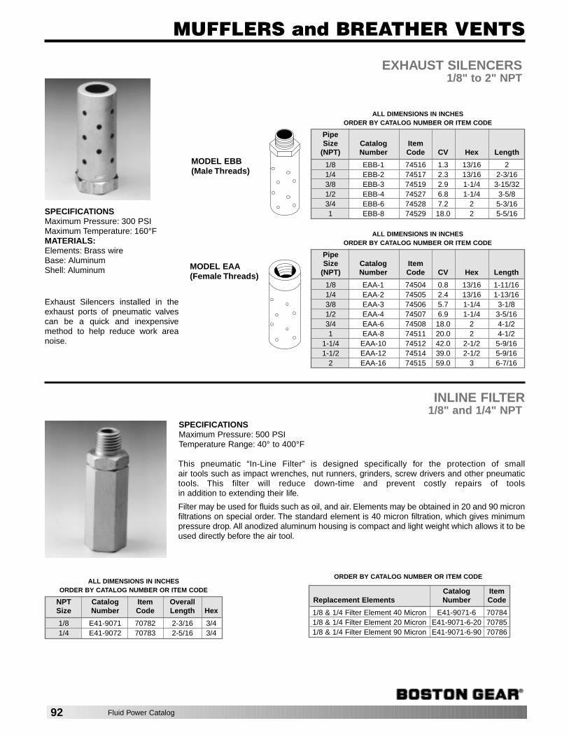
EXHAUST SILENCERS1/8" to 2" NPT
Exhaust Silencers installed in theexhaust ports of pneumatic valvescan be a quick and inexpensivemethod to help reduce work areanoise.
MUFFLERS and BREATHER VENTS
INLINE FILTER1/8" and 1/4" NPT
This pneumatic “In-Line Filter” is designed specifically for the protection of small air tools such as impact wrenches, nut runners, grinders, screw drivers and other pneumatictools. This filter will reduce down-time and prevent costly repairs of tools in addition to extending their life.
Filter may be used for fluids such as oil, and air. Elements may be obtained in 20 and 90 micronfiltrations on special order. The standard element is 40 micron filtration, which gives minimumpressure drop. All anodized aluminum housing is compact and light weight which allows it to beused directly before the air tool.
ALL DIMENSIONS IN INCHESORDER BY CATALOG NUMBER OR ITEM CODE
PipeSize Catalog Item
(NPT) Number Code CV Hex Length
1/8 EBB-1 74516 1.3 13/16 21/4 EBB-2 74517 2.3 13/16 2-3/163/8 EBB-3 74519 2.9 1-1/4 3-15/321/2 EBB-4 74527 6.8 1-1/4 3-5/83/4 EBB-6 74528 7.2 2 5-3/161 EBB-8 74529 18.0 2 5-5/16
ALL DIMENSIONS IN INCHESORDER BY CATALOG NUMBER OR ITEM CODE
PipeSize Catalog Item
(NPT) Number Code CV Hex Length
1/8 EAA-1 74504 0.8 13/16 1-11/161/4 EAA-2 74505 2.4 13/16 1-13/163/8 EAA-3 74506 5.7 1-1/4 3-1/81/2 EAA-4 74507 6.9 1-1/4 3-5/163/4 EAA-6 74508 18.0 2 4-1/21 EAA-8 74511 20.0 2 4-1/2
1-1/4 EAA-10 74512 42.0 2-1/2 5-9/161-1/2 EAA-12 74514 39.0 2-1/2 5-9/16
2 EAA-16 74515 59.0 3 6-7/16
MODEL EAA (Female Threads)
ALL DIMENSIONS IN INCHESORDER BY CATALOG NUMBER OR ITEM CODE
NPT Catalog Item OverallSize Number Code Length Hex
1/8 E41-9071 70782 2-3/16 3/41/4 E41-9072 70783 2-5/16 3/4
MODEL EBB (Male Threads)
SPECIFICATIONSMaximum Pressure: 300 PSIMaximum Temperature: 160°FMATERIALS:Elements: Brass wireBase: AluminumShell: Aluminum
SPECIFICATIONSMaximum Pressure: 500 PSITemperature Range: 40° to 400°F
Catalog ItemReplacement Elements Number Code
1/8 & 1/4 Filter Element 40 Micron E41-9071-6 707841/8 & 1/4 Filter Element 20 Micron E41-9071-6-20 707851/8 & 1/4 Filter Element 90 Micron E41-9071-6-90 70786
ORDER BY CATALOG NUMBER OR ITEM CODE
92 Fluid Power Catalog
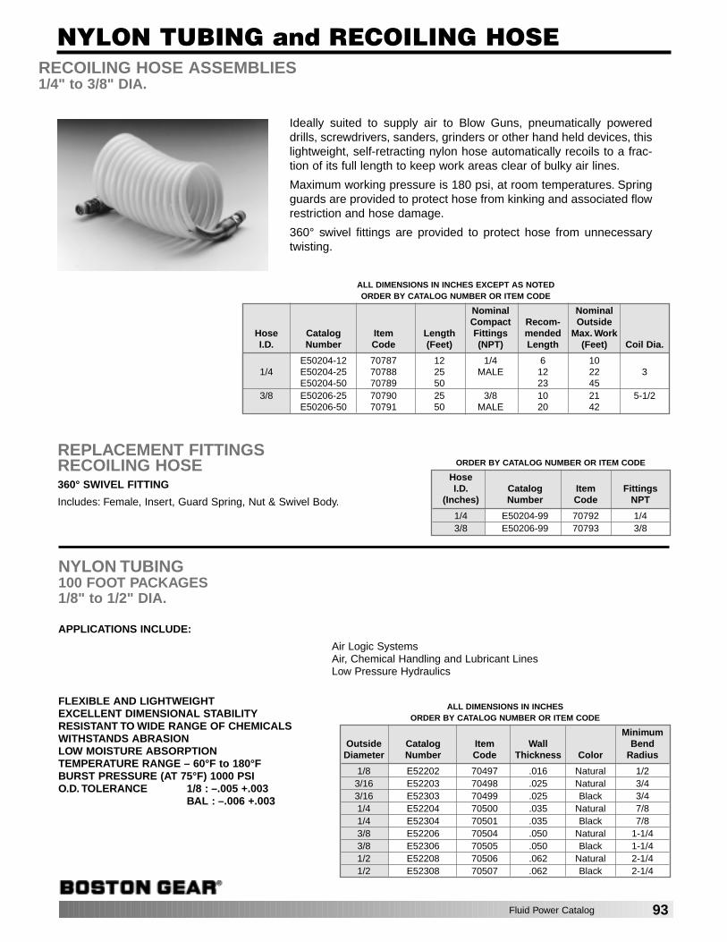
NYLON TUBING100 FOOT PACKAGES1/8" to 1/2" DIA.
APPLICATIONS INCLUDE:
Air Logic SystemsAir, Chemical Handling and Lubricant LinesLow Pressure Hydraulics
FLEXIBLE AND LIGHTWEIGHTEXCELLENT DIMENSIONAL STABILITYRESISTANT TO WIDE RANGE OF CHEMICALSWITHSTANDS ABRASIONLOW MOISTURE ABSORPTIONTEMPERATURE RANGE – 60°F to 180°FBURST PRESSURE (AT 75°F) 1000 PSIO.D. TOLERANCE 1/8 : –.005 +.003
BAL : –.006 +.003
RECOILING HOSE ASSEMBLIES1/4" to 3/8" DIA.
Ideally suited to supply air to Blow Guns, pneumatically powereddrills, screwdrivers, sanders, grinders or other hand held devices, thislightweight, self-retracting nylon hose automatically recoils to a frac-tion of its full length to keep work areas clear of bulky air lines.
Maximum working pressure is 180 psi, at room temperatures. Springguards are provided to protect hose from kinking and associated flowrestriction and hose damage.
360° swivel fittings are provided to protect hose from unnecessarytwisting.
REPLACEMENT FITTINGSRECOILING HOSE360° SWIVEL FITTING
Includes: Female, Insert, Guard Spring, Nut & Swivel Body.
NYLON TUBING and RECOILING HOSE
ALL DIMENSIONS IN INCHESORDER BY CATALOG NUMBER OR ITEM CODE
MinimumOutside Catalog Item Wall Bend
Diameter Number Code Thickness Color Radius
1/8 E52202 70497 .016 Natural 1/23/16 E52203 70498 .025 Natural 3/43/16 E52303 70499 .025 Black 3/41/4 E52204 70500 .035 Natural 7/81/4 E52304 70501 .035 Black 7/83/8 E52206 70504 .050 Natural 1-1/43/8 E52306 70505 .050 Black 1-1/41/2 E52208 70506 .062 Natural 2-1/41/2 E52308 70507 .062 Black 2-1/4
ALL DIMENSIONS IN INCHES EXCEPT AS NOTEDORDER BY CATALOG NUMBER OR ITEM CODE
Nominal NominalCompact Recom- Outside
Hose Catalog Item Length Fittings mended Max. WorkI.D. Number Code (Feet) (NPT) Length (Feet) Coil Dia.
E50204-12 70787 12 1/4 6 101/4 E50204-25 70788 25 MALE 12 22 3
E50204-50 70789 50 23 453/8 E50206-25 70790 25 3/8 10 21 5-1/2
E50206-50 70791 50 MALE 20 42
ORDER BY CATALOG NUMBER OR ITEM CODE
HoseI.D. Catalog Item Fittings
(Inches) Number Code NPT
1/4 E50204-99 70792 1/43/8 E50206-99 70793 3/8
Fluid Power Catalog 93
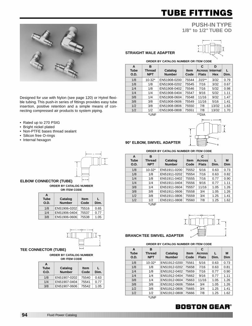
PUSH-IN TYPE1/8" to 1/2" TUBE OD
ELBOW CONNECTOR (TUBE)
TEE CONNECTOR (TUBE)
TUBE FITTINGS
L
A
A
L
C
B
D
L
A
ORDER BY CATALOG NUMBER OR ITEM CODE
ATube Catalog Item LO.D. Number Code Dim.
1/8 EN51906-0202 75516 0.651/4 EN51906-0404 75537 0.773/8 EN51906-0606 75538 1.05
L
A
A
L L
A
ORDER BY CATALOG NUMBER OR ITEM CODE
ATube Catalog Item LO.D. Number Code Dim.
1/8 EN51907-0202 75540 0.631/4 EN51907-0404 75541 0.773/8 EN51907-0606 75542 1.05
ORDER BY CATALOG NUMBER OR ITEM CODE
A B C DTube Thread Catalog Item Across Internal LO.D. NPT Number Code Flats Hex Dim.
1/8 10-32* EN51908-0200 75544 .315** 3/32 0.791/8 1/8 EN51908-0202 75545 7/16 3/32 0.671/4 1/8 EN51908-0402 75546 7/16 5/32 0.981/4 1/4 EN51908-0404 75547 9/16 5/32 1.113/8 1/4 EN51908-0604 75548 11/16 9/32 1.473/8 3/8 EN51908-0606 75549 11/16 5/16 1.411/2 3/8 EN51908-0806 75550 7/8 13/32 1.631/2 1/2 EN51908-0808 75551 7/8 13/32 1.70
STRAIGHT MALE ADAPTER
ORDER BY CATALOG NUMBER OR ITEM CODE
A B CTube Thread Catalog Item Across L MO.D. NPT Number Code Flats Dim. Dim
1/8 10-32* EN51912-0200 75561 5/16 0.63 0.731/8 1/8 EN51912-0202 75658 7/16 0.63 0.811/4 1/8 EN51912-0402 75659 7/16 0.77 0.901/4 1/4 EN51912-0404 75662 9/16 0.77 1.113/8 1/4 EN51912-0604 75663 11/16 1.05 1.263/8 3/8 EN51912-0606 75664 3/4 1.05 1.261/2 3/8 EN51912-0806 75665 3/4 1.25 1.411/2 1/2 EN51912-0808 75666 7/8 1.25 1.62
BRANCH TEE SWIVEL ADAPTER
L
A
B
MC
M
AA
C
B
LL
ORDER BY CATALOG NUMBER OR ITEM CODE
A B CTube Thread Catalog Item Across L MO.D. NPT Number Code Flats Dim. Dim
1/8 10-32* EN51911-0200 75552 5/16 0.63 0.731/8 1/8 EN51911-0202 75554 7/16 0.63 0.821/4 1/8 EN51911-0402 75555 7/16 0.77 0.901/4 1/4 EN51911-0404 75556 9/16 0.77 1.113/8 1/4 EN51911-0604 75557 11/16 1.05 1.263/8 3/8 EN51911-0606 75558 3/4 1.05 1.261/2 3/8 EN51911-0806 75559 3/4 1.25 1.411/2 1/2 EN51911-0808 75560 7/8 1.25 1.62
90° ELBOW, SWIVEL ADAPTER
Designed for use with Nylon (see page 120) or Hytrel flexi-ble tubing. This push-in series of fittings provides easy tubeinsertion, positive retention and a simple means of con-necting compressed air products to system piping.
• Rated up to 270 PSIG• Bright nickel plated• Non-PTFE bases thread sealant• Silicon free O-rings• Internal hexagon
*UNF **DIA
*UNF
*UNF
94 Fluid Power Catalog

BLOW GUNS
FEATURES:
FLOW STABILIZER VALVE for precise air control
CONTOURED DESIGN to comfortably fit operator’s hand
CHROME PLATED, LIGHTWEIGHT ZINC BODY
CUSHIONED THUMB LEVER
LARGE HANGING HOOK
MEETS OSHA REQUIREMENTS of 30 PSI maximum outlet pressurewhen dead-ended up to 150 PSI inlet pressure
STANDARDMODEL
SUPER BOOSTER MODEL
High Flow at Lower Velocity
PLASTIC THUMB GRIPCUSHIONED GRIP EASES THUMB FATIGUE
NICKEL PLATED LEVERRESISTS CORROSION
NICKEL PLATED RIVETCORROSION RESISTANT
BUNA “N” O-RING(3) O-RINGS IN SYSTEM ASSURE ZERO LEAKAGE
JET CONCENTRATORINITIATES VENTURI ACTION
VENT HOLESLIMITS TIP PRESSURE TO 30 PSIWHEN DEAD-ENDED
BRASS FLOW STABILIZER VALVENON-CORROSIVE
STAINLESS STEEL SPRING
CONVENIENT LARGE HOOKFOR HANGING GUN ON PIPESUP TO 1" DIAMETER
ZINC BODY WITH CHROME FINISHLIGHTWEIGHT AND DURABLE
ORDER BY CATALOG NUMBER OR ITEM NUMBER
Port Catalog ItemNPT Number Code
Standard1/4 BE65A 71667
Super Booster1/4 BE65SB 76827
BLOW GUNS1/4" NPT
Fluid Power Catalog 95
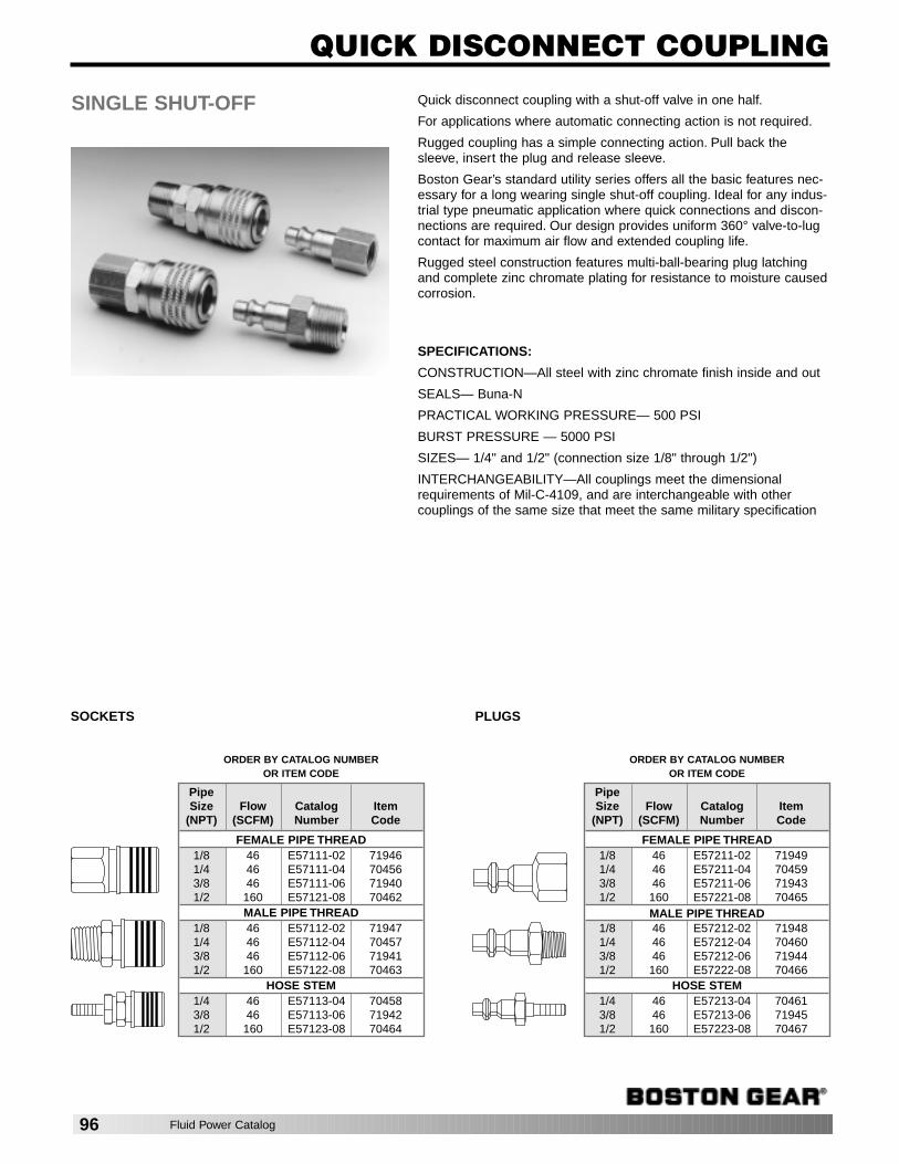
ORDER BY CATALOG NUMBER OR ITEM CODE
QUICK DISCONNECT COUPLING
SINGLE SHUT-OFF Quick disconnect coupling with a shut-off valve in one half.
For applications where automatic connecting action is not required.
Rugged coupling has a simple connecting action. Pull back thesleeve, insert the plug and release sleeve.
Boston Gear’s standard utility series offers all the basic features nec-essary for a long wearing single shut-off coupling. Ideal for any indus-trial type pneumatic application where quick connections and discon-nections are required. Our design provides uniform 360° valve-to-lugcontact for maximum air flow and extended coupling life.
Rugged steel construction features multi-ball-bearing plug latchingand complete zinc chromate plating for resistance to moisture causedcorrosion.
SPECIFICATIONS:
CONSTRUCTION—All steel with zinc chromate finish inside and out
SEALS— Buna-N
PRACTICAL WORKING PRESSURE— 500 PSI
BURST PRESSURE — 5000 PSI
SIZES— 1/4" and 1/2" (connection size 1/8" through 1/2")
INTERCHANGEABILITY—All couplings meet the dimensionalrequirements of Mil-C-4109, and are interchangeable with othercouplings of the same size that meet the same military specification
SOCKETS PLUGS
ORDER BY CATALOG NUMBER OR ITEM CODE
PipeSize Flow Catalog Item
(NPT) (SCFM) Number Code
FEMALE PIPE THREAD1/8 46 E57111-02 719461/4 46 E57111-04 704563/8 46 E57111-06 719401/2 160 E57121-08 70462
MALE PIPE THREAD1/8 46 E57112-02 719471/4 46 E57112-04 704573/8 46 E57112-06 719411/2 160 E57122-08 70463
HOSE STEM1/4 46 E57113-04 704583/8 46 E57113-06 719421/2 160 E57123-08 70464
PipeSize Flow Catalog Item
(NPT) (SCFM) Number Code
FEMALE PIPE THREAD1/8 46 E57211-02 719491/4 46 E57211-04 704593/8 46 E57211-06 719431/2 160 E57221-08 70465
MALE PIPE THREAD1/8 46 E57212-02 719481/4 46 E57212-04 704603/8 46 E57212-06 719441/2 160 E57222-08 70466
HOSE STEM1/4 46 E57213-04 704613/8 46 E57213-06 719451/2 160 E57223-08 70467
96 Fluid Power Catalog
SAFETY WARNINGSAIR PREPARATION PRODUCTSThese Filter/Regulator/Lubricators are intended for use in industrial compressed air systemsonly. They must not be used where the pressure or temperature may exceed the maximum ratedoperating conditions. Before using with fluids other than air, for non-industrial applications, or forlife support systems consult Boston Gear.
The polycarbonate plastic bowls used on some of these Filter/Regulator/Lubricators can bedamaged and possibly burst if exposed to such substances as certain solvents, strong alkalies,compressor oils containing ester-based additives or synthetic oils. Fumes of these substances incontact with the polycarbonate bowl, externally or internally, can also result in damage. Cleanwith warm water only. Use a metal bowl in applications where a plastic bowl might be exposed tosubstances that are incompatible with the polycarbonate.
If the outlet pressures in excess of the Filter/Regulator/Lubricators pressure setting could causedownstream equipment to rupture or malfunction, install a pressure relief device downstream ofthe Filter/Regulator/Lubricators. The relief pressure and flow capacity of the relief device mustsatisfy the system requirements.
In lubrication applications, some oil mist may escape from the point of use into the surroundingatmosphere. Users are referred to OSHA Safety and Health Standards for Limiting Oil MistContamination and Utilization of Protecting Equipment. Through misuse, age, or malfunction,components used in fluid power systems can fail in various modes. The system designer iswarned to consider the failure modes of all component parts used in the fluid power systemsand to provide adequate safeguards to prevent personal injury or damage to equipment in theevent of such failure modes.
System designers must provide a warning to end users in the system instruction manualif protection against a failure mode cannot be adequately provided.
System designers and end users are cautioned to review specific warnings found in the instruc-tion sheets packed and shipped with these products.
CONTROL VALVE PRODUCTSThese products are intended for use in industrial compressed air systems only. They must notbe used where pressures and temperatures can exceed those listed under Specification.
Before using these products with fluids other than those specified, for nonindustrial applications,life-support systems, or other applications not within published specifications, consult Boston Gear.
Through misuse, age, or malfunction, components used in fluid power systems can fail in vari-ous modes. The system designer is warned to consider the failure modes of all component partsused in the fluid power systems and to provide adequate safeguards to prevent personal injuryor damage to equipment in the event of such failure modes. System designers must provide awarning to end users in the system instruction manual if protection against a failuremode cannot be adequately provided.
System designers and end users are cautioned to review specific warnings found in the instruc-tion sheets packed and shipped with these products. System designers should also provide forall OSHA requirements including Title 29 CFR 1910.147 Lockout/Tagout.
Fluid Power Catalog 97

w w w . b o s t o n g e a r . c o m
Printed in USA
Boston Gear14 Hayward Street • Quincy, MA 02171617-328-3300 • Fax: 617-479-6238www.bostongear.com
P-1483-BG 50117 8/07
Warner ElectricElectromagnetic Clutches and Brakes - USA
South Beloit, IL815-389-3771For application assistance:1-800-825-9050
Electromagnetic Clutches and Brakes - Europe
St Barthelemy d’Anjou, France+33 (0)2 41 21 24 24For sales office:+33 (0)2 41 21 24 76
Precision Electric Coils andElectromagnetic Clutches and Brakes - USA
Columbia City, IN260-244-6183
Inertia Dynamics Spring Set Brakes; Power On andWrap Spring Clutch/Brakes
Torrington, CT860-482-4444
Matrix InternationalElectromagnetic Clutches and Brakes, Pressure Operated Clutches and Brakes
Brechin, Scotland+44 (0) 1356 602000U.S.815-389-3771
Warner LinearLinear Actuators and Guideways - USA
Belvidere, IL815-547-1106For application assistance:1-800-825-9050
TB Wood’sV-Belt Drives, Synchronous Drives,Flexible Couplings, VariableFrequency AC Drives
Chambersburg, PA717-264-7161
For assistance:1-888-829-6637Press #5 - Customer ServicePress #7 - Mechanical ApplicationsPress #8 - Electrinic Applications
Wichita Clutch and Industrial ClutchPneumatic and Oil ImmersedClutches and Brakes - USA
Wichita Falls, TX940-723-3400
Pneumatic Clutches and Brakes - Europe
Bedford, England+44 (0)1234 350311
Twiflex LimitedCaliper Brakes and Thrusters
Twickenham, England+44 (0) 20 8894 1161
Formsprag Clutch
Overrunning Clutches and Holdbacks
Warren, MI 48089586-758-5000For application assistance:1-800-927-3262
Marland ClutchRoller Ramp and Sprag Type Overrunning Clutches and Backstops
Burr Ridge, IL630-455-1752
Stieber Clutch Overrunning Clutches and Holdbacks
Heidelberg, Germany+49 (0)6221 30 47 0
Boston GearEnclosed and Open Gearing, Electrical and Mechanical P.T. Components
Charlotte, NC704-688-7300For customer service:1-888-999-9860
For application assistance:1-800-816-5608
Huco DynatorkPrecision Couplings and Air Motors
Hertford, England+44 (0) 1992 501900U.S.800-825-6544
Ameridrives CouplingsGear Couplings, Mill Spindles,Universal Joints
Erie, PA814-480-5000
Bibby TransmissionsDisc, Gear, Grid Couplings, Overload Clutches
Dewsbury, England+44 (0) 1924 460801
Nuttall Gear andDelroyd Worm GearWorm Gear and Helical Speed Reducers
Niagara Falls, NY716-298-4100
Saftek FrictionNon-asbestos Brake and ClutchMaterials
Telford, England+44 (0) 1952 581122
Altra Industrial Motion -Asia Pacific and Africa
China 852 2615 9313
Taiwan 886 2 2577 8156
Singapore 65 6487 4464
Thailand 66 2 322 5527
Australia 612 9894 0133
S. Africa 27 11 918 4270