Bearing Capacity of Eccentrically
17
Tikrit Journal of Eng. Sciences/Vol.14/No.2/June 2007 BEARING CAPACITY OF ECCENTRICALLY LOADED STRIP FOOTING NEAR THE EDGE OF COHESIVE SLOPE Dr. Haider S. Al-Jubair Dr. Jawdat K. Abbas Assistant Professor Assistant Professor University of Thi-Qar University of Tikrit Department of Civil Engineering ABSTRACT The finite element method is used to investigate the behavior of a strip footing constructed near the edge of a sloping cohesive ground. The effects of variation in footing closeness, loading eccentricity and slope angle are studied also. It is proved that Bowles method overestimates the load carrying capacity of the concentrically loaded strip footings on cohesive soils. Decreasing the distance between the footing and the slope edge, increasing the eccentricity and slope angle reduce the ultimate bearing capacity. Slope effect diminishes as the footing distance from the edge approaches (1.5) times its width. KEY WORDS Bearing capacity, finite element, slope, strip footing. 32 (32-48)
-
Upload
mohamed-mohsen -
Category
Documents
-
view
24 -
download
3
Transcript of Bearing Capacity of Eccentrically

Tikrit Journal of Eng. Sciences/Vol.14/No.2/June 2007
BEARING CAPACITY OF ECCENTRICALLY
LOADED STRIP FOOTING NEAR THE EDGE OF
COHESIVE SLOPE
Dr. Haider S. Al-Jubair Dr. Jawdat K. Abbas
Assistant Professor Assistant Professor
University of Thi-Qar University of Tikrit
Department of Civil Engineering
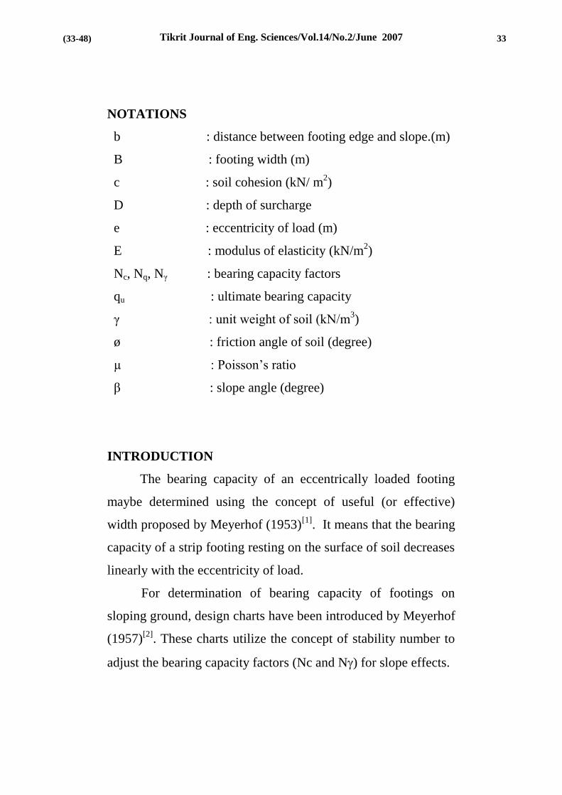
ABSTRACT
The finite element method is used to investigate the
behavior of a strip footing constructed near the edge of a sloping
cohesive ground. The effects of variation in footing closeness,
loading eccentricity and slope angle are studied also. It is proved
that Bowles method overestimates the load carrying capacity of
the concentrically loaded strip footings on cohesive soils.
Decreasing the distance between the footing and the slope edge,
increasing the eccentricity and slope angle reduce the ultimate
bearing capacity. Slope effect diminishes as the footing distance
from the edge approaches (1.5) times its width.
KEY WORDS
Bearing capacity, finite element, slope, strip footing.
32 (32-48)
Tikrit Journal of Eng. Sciences/Vol.14/No.2/June 2007
NOTATIONS
b : distance between footing edge and slope.(m)
B : footing width (m)
c : soil cohesion (kN/ m2)
D : depth of surcharge
e : eccentricity of load (m)
E : modulus of elasticity (kN/m2)
Nc, Nq, Nγ : bearing capacity factors
qu : ultimate bearing capacity
γ : unit weight of soil (kN/m3)
ø : friction angle of soil (degree)
µ : Poisson’s ratio
β : slope angle (degree)
INTRODUCTION
The bearing capacity of an eccentrically loaded footing
maybe determined using the concept of useful (or effective)
width proposed by Meyerhof (1953)[1]
. It means that the bearing
capacity of a strip footing resting on the surface of soil decreases
linearly with the eccentricity of load.
For determination of bearing capacity of footings on
sloping ground, design charts have been introduced by Meyerhof
(1957)[2]
. These charts utilize the concept of stability number to
adjust the bearing capacity factors (Nc and N) for slope effects.
33 (33-48)

Tikrit Journal of Eng. Sciences/Vol.14/No.2/June 2007
Since the lack of soil on the slope side tend to reduce the stability
of the footing, Bowles (1988)[3]
developed a table for adjusted
factors (Nc and Nq) based on the reduction in slip surface length
and surcharge area, respectively.
The objective of this work is to explore the combined
effect of loading eccentricity and the slope on bearing capacity
and to provide the geotechnical engineer with useful design
charts.
BEARING CAPACITY BY FINITE ELEMENT METHOD
The ultimate soil bearing capacity under a strip footing is
generally calculated using equation (1), in which the bearing
resistance is approximated by superposition of three basic
components, Bowles (1988)[3]
qu = c.Nc + q .Nq. + 0.5γBNγ……………………….....…(1)
Where
B = foundation width.
c = soil cohesion.
γ = soil unit weight.
Nc, Nq, Nγ = bearing capacity factors = f(ø)
qu = ultimate bearing capacity of soil
q = effective over burden pressure at foundation level.
ø = soil angle of internal friction.
The Finite element method was utilized with plasticity
theory, to predict the ultimate bearing capacity for a footing
resting on (c-ø) soil in conjunction with Terzaghi's equation. In
34 (34-48)

Tikrit Journal of Eng. Sciences/Vol.14/No.2/June 2007
order to isolate the contribution of each component, Griffiths
(1982)[4]
adopted three cases to find the bearing capacity factors:
weightless cohesive soil with no surcharge; weightless,
cohesionless soil under uniform surface surcharge; cohesionless
soil with self-weight.
If the footing rests on the surface of the soil, equation (1)
reduces to;
qu = c.Nc + 0.5γBNγ….…………………...…………..(2)
If the soil under footing is a clayly soil under undrained
conditions, equation (2) could be rewritten as:
qu = c.Nc…..….…………….……….…..……………..(3)
DESCRIPTION OF PROBLEM
A concrete strip footing resting on the surface of a clayey
soil is analyzed. The geometric configuration of the problem is
illustrated in figure (1). Material properties of both concrete
[Winter and Nilson (1979)][5]
and soil [Bowles (1988)][3]
are
listed in table (1).
The finite element method is utilized to predict the
ultimate bearing capacity. The general matrix equations for a
deformable solid under external loading can be found in many
texts [e.g. Bathe (1996)][6]
. A computer program using eight-
node quadrilateral elements is drawn from Smith and Griffiths
(1998)[7]
and modified by the authors to account for the
difference in element properties and the mesh generation of
distorted geometry due to the presence of slope. It employs the
35 (35-48)

Tikrit Journal of Eng. Sciences/Vol.14/No.2/June 2007
visco-plastic method to compute the response to loading of
elastic-plastic von Mises material.
RESULTS AND DISCUSSION
Footings at different distances from the edge of a slope,
with variable slope angle and subjected to a range of
eccentricities are analyzed. The results are shown in table (2). It
is clear that the slope effect vanishes at a distance ratio (b/B =
1.5).
In order to isolate the effect of slope from that of
eccentricity, table (3) is prepared for the case of (e/B = 0 and D/B
= 0). The reduction factor of slope effect alone (Rs) represents
the ratio between the bearing capacity of footing adjacent to
slope and that of the same footing on flat ground. The results are
compared to their (available) counterparts calculated using
Bowles approach. It can be realized that Bowles approach gives
higher values of (Rs). It should be mentioned that Al-Jubair
(2004)[8]
proved that the principle of effective width gives
conservative values for the load carrying capacity of footings on
cohesive soils compared to the finite element method.
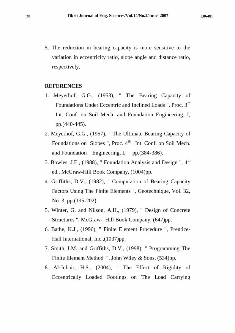
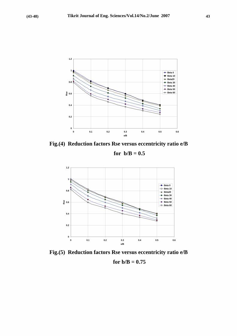
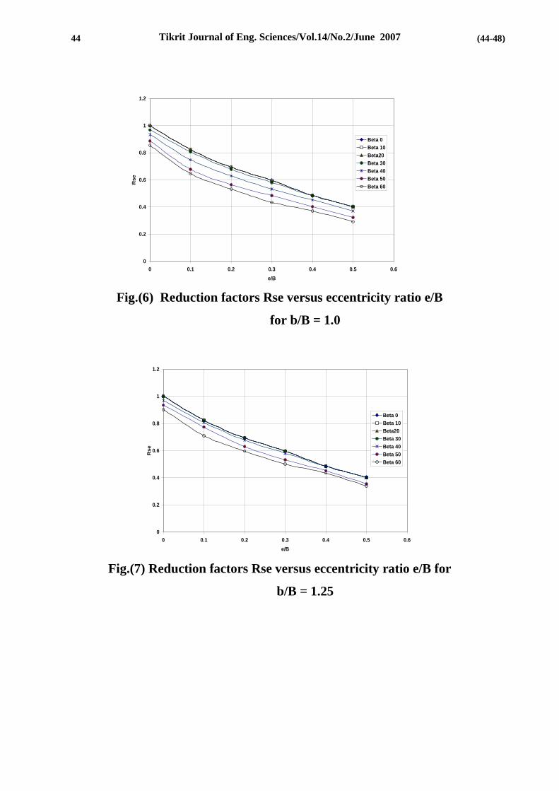
Figures (2 through 7) show the variation of the reduction
factor, due to slope and eccentricity effects (Rse), with the
eccentricity ratio (e/B) for different values of slope angle () and
distance ratio (b/B). It can be deduced that the reduction factor
36 (36-48)

Tikrit Journal of Eng. Sciences/Vol.14/No.2/June 2007
decreases with the increase of eccentricity ratio. The effect of
slope angle is more pronounced at low values of distance ratio.
It is apparent from figures (8 through 10) that the reduction
factor reduces as the slope angle increases. The effect of distance
ratio increases with the eccentricity ratio increase.
It can be observed from figures (11 through 13) that the
reduction factor is proportional with the variation of distance
ratio. The effect of slope angle is greater for high values of
eccentricity ratio.
CONCLUSIONS
1. For the studied values, which cover the practical ranges, it can
be noted that the effect of slope diminishes as the distance
ratio approaches (1.5).
2. Bowles approach overestimates the load carrying capacity of
the concentrically loaded footings on slopes, compared to the
finite element method.
3. Negative eccentricity reduces the bearing capacity to a lesser
degree than its counterpart, since it deflects the failure zone
away from the slope.
4. It is clearly demonstrated that the load carrying capacity is
decreased as the footing becomes closer to a steeper slope and
subjected to larger eccentricity.
Tikrit Journal of Eng. Sciences/Vol.14/No.2/June 2007
5. The reduction in bearing capacity is more sensitive to the
variation in eccentricity ratio, slope angle and distance ratio,
respectively.
REFERENCES
1. Meyerhof, G.G., (1953), " The Bearing Capacity of
Foundations Under Eccentric and Inclined Loads ", Proc. 3rd
Int. Conf. on Soil Mech. and Foundation Engineering, I,
pp.(440-445).
2. Meyerhof, G.G., (1957), " The Ultimate Bearing Capacity of
Foundations on Slopes ", Proc. 4th
Int. Conf. on Soil Mech.
and Foundation Engineering, I, pp.(384-386).
3. Bowles, J.E., (1988), " Foundation Analysis and Design ", 4th
ed., McGraw-Hill Book Company, (1004)pp.
4. Griffiths, D.V., (1982), " Computation of Bearing Capacity
Factors Using The Finite Elements ", Geotechnique, Vol. 32,
No. 3, pp.(195-202).
5. Winter, G. and Nilson, A.H., (1979), " Design of Concrete
Structures ", McGraw- Hill Book Company, (647)pp.
6. Bathe, K.J., (1996), " Finite Element Procedure ", Prentice-
Hall International, Inc.,(1037)pp.
7. Smith, I.M. and Griffiths, D.V., (1998), " Programming The
Finite Element Method ", John Wiley & Sons, (534)pp.
8. Al-Jubair, H.S., (2004), " The Effect of Rigidity of
Eccentrically Loaded Footings on The Load Carrying
38
5
(38-48)

Tikrit Journal of Eng. Sciences/Vol.14/No.2/June 2007
Capacity ", Engineering & Technology Journal, Vol. 23,
No.12, pp.(790-798).
Table (1) Material properties
Material
Properties Clay Concrete
Cu (kN/ m2) 50 1650 × 10
2
ø (degree) 0.0 50
E (kN/ m2) 0.5 × 10
5 250× 10
5
µ 0.5 0.15
39
85
(39-48)

Tikrit Journal of Eng. Sciences/Vol.14/No.2/June 2007
Table(2)Ultimate Bearing Capacity (kN/m2) for strip footing
near slope under for different values of (b/B, e/B, ß ) b/B =0.25 b/B =0.0
0.5 0.4 0.3 0.2 0.1 0.0 -0.1
e/B
ß
0.5 0.4 0.3 0.2 0.1 0.0 -0.1
e/B
ß
125 150 185 215 255 310 255 0.0 125 150 185 215 255 310 255 0.0
120 145 175 210 245 300 250 10 110 142 170 200 237 292 240 10
112 140 170 195 235 290 245 20 100 130 165 185 220 275 225 20
100 125 150 180 215 270 230 30 90 115 145 170 205 262 215 30
90 110 135 160 192 255 215 40 80 110 125 150 185 245 200 40
80 95 120 145 175 245 200 50 70 90 110 135 165 228 180 50
70 90 105 135 165 235 190 60 60 75 195 115 145 215 165 60
b/B =0.75 b/B =0. 5
0.5 0.4 0.3 0.2 0.1 0.0 -0.1
e/B
ß
0.5 0.4 0.3 0.2 0.1 0.0 -0.1
e/B
ß
125 150 185 215 255 310 255 0.0 125 150 185 215 255 310 255 0.0
125 150 185 215 255 310 255 10 125 150 185 215 250 305 255 10
125 150 180 212 250 305 250 20 120 145 175 205 242 300 250 20
115 145 170 200 240 295 245 30 105 132 162 195 225 282 242 30
100 130 155 185 220 282 240 40 95 120 145 170 205 265 232 40
90 115 140 165 200 265 235 50 85 105 155 180 252 215 50
85 105 125 155 185 255 225 60 75 95 115 142 175 2452 205 60
b/B =1.25 b/B =1.00
0.5 0.4 0.3 0.2 0.1 0.0 -0.1
e/B
ß
0.5 0.4 0.3 0.2 0.1 0.0 -0.1
e/B
ß
125 150 185 215 255 310 255 0.0 125 150 185 215 255 310 255 0.0
125 150 185 215 255 310 255 10 125 150 185 215 255 310 255 10
125 150 185 215 255 310 255 20 125 150 185 215 255 310 255 20
125 150 185 215 255 310 255 30 125 150 180 210 250 300 255 30
125 150 180 210 250 300 255 40 115 140 165 195 232 290 245 40
110 140 165 195 240 290 250 50 100 125 150 175 210 275 242 50
105 135 155 185 220 280 245 60 900 115 135 165 200 265 232 60
b/B =2.00 b/B =1. 5
0.5 0.4 0.3 0.2 0.1 0.0 -0.1
e/B
ß
0.5 0.4 0.3 0.2 0.1 0.0 -0.1
e/B
ß
125 150 185 215 255 310 255 0.0 125 150 185 215 255 310 255 0.0
10 125 150 185 215 255 310 255 10
20 125 150 185 215 255 310 255 20
30 125 150 185 215 255 310 255 30
40 125 150 185 215 255 310 255 40
50 125 150 185 215 255 310 255 50
60 125 150 185 215 255 310 255 60
35
39
40
5
(40-48)

Tikrit Journal of Eng. Sciences/Vol.14/No.2/June 2007
Table (3) The Values of slope reduction factor (Rs) for different
slope angles () And distance ratios (b/B) [(e/B = 0) , (D/B = 0)].
(deg)
b/B
0
10
20
30
60
Approach
0
1 0.942 0.887 0.845 0.694 F.E.M.
1 0.951 0.901 0.852 0.704 Bowles
0.75
1 1 0.984 0.952 0.823 F.E.M.
1 1 1 1 1 Bowles
Fig.(1) The geometric configurations of the footing used in
this study
βo
b
B=2m
e
Q
7.5m
41
05
(41-48)

Tikrit Journal of Eng. Sciences/Vol.14/No.2/June 2007
Fig.(2) Reduction factors Rse versus eccentricity ratio e/B
for b/B = 0.0.
Fig.(3) Reduction factors Rse versus eccentricity ratio e/B
for b/B = 0.25
0
0.2
0.4
0.6
0.8
1
1.2
0 0.1 0.2 0.3 0.4 0.5 0.6
e/B
Rs
e
Beta 0
Beta 10
Beta20
Beta 30
Beta 40
Beta 50
Beta 60
0
0.2
0.4
0.6
0.8
1
1.2
0 0.1 0.2 0.3 0.4 0.5 0.6
e/B
Rse
Beta 0
Beta 10
Beta20
Beta 30
Beta 40
Beta 50
Beta 60
42
10
5
(42-48)
Tikrit Journal of Eng. Sciences/Vol.14/No.2/June 2007
Fig.(4) Reduction factors Rse versus eccentricity ratio e/B
for b/B = 0.5
Fig.(5) Reduction factors Rse versus eccentricity ratio e/B
for b/B = 0.75
0
0.2
0.4
0.6
0.8
1
1.2
0 0.1 0.2 0.3 0.4 0.5 0.6
e/B
Rse
Beta 0
Beta 10
Beta20
Beta 30
Beta 40
Beta 50
Beta 60
0
0.2
0.4
0.6
0.8
1
1.2
0 0.1 0.2 0.3 0.4 0.5 0.6
e/B
Rse
Beta 0
Beta 10
Beta20
Beta 30
Beta 40
Beta 50
Beta 60
43
10
5
(43-48)
Tikrit Journal of Eng. Sciences/Vol.14/No.2/June 2007
Fig.(6) Reduction factors Rse versus eccentricity ratio e/B
for b/B = 1.0
Fig.(7) Reduction factors Rse versus eccentricity ratio e/B for
b/B = 1.25
0
0.2
0.4
0.6
0.8
1
1.2
0 0.1 0.2 0.3 0.4 0.5 0.6
e/B
Rse
Beta 0
Beta 10
Beta20
Beta 30
Beta 40
Beta 50
Beta 60
0
0.2
0.4
0.6
0.8
1
1.2
0 0.1 0.2 0.3 0.4 0.5 0.6
e/B
Rse
Beta 0
Beta 10
Beta20
Beta 30
Beta 40
Beta 50
Beta 60
44
31
05
(44-48)

Tikrit Journal of Eng. Sciences/Vol.14/No.2/June 2007
Fig.(8) Reduction factors Rse versus slope angle (β) for
e/B = 0.0.
Fig.(9) Reduction factors Rse versus slope angle (β) for
e/B = 0.2
0
0.2
0.4
0.6
0.8
1
1.2
0 10 20 30 40 50 60
Beta (degree)
Rse
b/B =0.0
b/B =0.25
b/B =0.5
b/B =0.75
b/B =1.0
b/B =1.25
b/B =1.5
0
0.1
0.2
0.3
0.4
0.5
0.6
0.7
0.8
0 10 20 30 40 50 60
Beta (degree)
Rs
e
b/B =0.0
b/B =0.25
b/B =0.5
b/B =0.75
b/B =1.0
b/B =1.25
b/B =1.5
45 (45-48)

Tikrit Journal of Eng. Sciences/Vol.14/No.2/June 2007
Fig.(10) Reduction factors Rse versus slope angle (β) for
e/B = 0.4
Fig.(11) Reduction factors Rse versus edge distance ratio b/B
for e/B = 0.0.
0
0.2
0.4
0.6
0.8
1
1.2
0 0.25 0.5 0.75 1 1.25 1.5 1.75 2 2.25
b/B
Rse
Beta0.
Beta 10
Beta 20
Beta 30
Beta 40
Beta 50
Beta 60
0
0.1
0.2
0.3
0.4
0.5
0.6
0 10 20 30 40 50 60
Beta (degree)
Rs
e
b/B =0.0
b/B =0.25
b/B =0.5
b/B =0.75
b/B =1.0
b/B =1.25
b/B =1.5
46
5
(46-48)

Tikrit Journal of Eng. Sciences/Vol.14/No.2/June 2007
Fig.(12) Reduction factors Rse versus edge distance ratio b/B
for e/B = 0.2
Fig.(13) Reduction factors Rse versus edge distance ratio b/B
for e/B = 0.4
0
0.1
0.2
0.3
0.4
0.5
0.6
0.7
0.8
0 0.25 0.5 0.75 1 1.25 1.5 1.75 2 2.25
b/B
Rse
Beta0.
Beta 10
Beta 20
Beta 30
Beta 40
Beta 50
Beta 60
0
0.1
0.2
0.3
0.4
0.5
0.6
0 0.25 0.5 0.75 1 1.25 1.5 1.75 2 2.25
b/B
Rse
Beta0.
Beta 10
Beta 20
Beta 30
Beta 40
Beta 50
Beta 60
47
31
05
(47-48)

Tikrit Journal of Eng. Sciences/Vol.14/No.2/June 2007
شريطي المحمل مركزيا" والمجاورة اس القابمية التحمل القصوى لالس لممنحدرات
د. جودت كاظم عباسد. حيدر سعد ياسين
استاذ مساعد استاذ مساعد
جامعة ذي قار جامعة تكريت
الهندسة المدنية قسم
الخالصة
ذبسيي امب ذيقة ييعذب ر الييقذب لمييمم ذ مييق ذ يي ذ لييق ذذفييهذاييلبذب تميي ذ يي ذذألملييييا ب ل شييييلذتييييا قنذليييي ذب ل مييييمقبمذب لاسيييي ةعذذ ب لرييييق ذذب شييييقةيهذذألسييييا ب
ييي ذذبألسيييا ل مةييعذرةيييقذلق ةيييعذتذ يييلاةقذ مةيييقلذ ب ةيييعذلييية ذب ل ميييمقذلتريييمذمافيييعذذ ألسيا ب لسي يعذ يقذبات ةيعذب ملي ذب لي ذذ ألمليا ذب ل ممقلذ ذ يلاةقذب لق ةيع
ذب شقةيهذب لمل ذاللق ةا"ذ ب لجا قذ ل ممقبمذذ ذب مق ذ هاذبةضا"ت
مافيييعذب ل ميييمقذلذ ةيييام ذذبألسيييا يييابلذب لسيييافعذتييية ذذب ييياانذب أظهيييقمذذذسيا ألب لي ذذبات ةيعذب ملي لي ذذب لق ةعذ مل ذ ةام ذ ب ةعذلة ذب ل ميمقذ ي
ب يياانذب ذذأظهييقمرةييقذلق ةيعت لاذذألملييا ب لجييا قذ ل مييمقبمذ ب لريق ذذب شيقةيه(ذلييق ذت ييمقذ1.5 يي ذب ل مييمقذذذذذ ذبألسييا ييلاةقذب ل مييمقذة شييقذ ييملاذة يي ذترييمذ
ذتذبألسا ق ذ
لةاكممات الدال
بات ةعذ مل ذب قتعلذب ر القذب لممم لب ل ممقبملبسا ذشقةيهت
48
31
05
(48-48)