Bearing Capacity and Driving Efficiency of Ecological ... · 32 JFE TECHNICAL REPORT No. 19 (Mar....
8
30 Abstract: “Tsubasa Pile TM ” developed by JFE Steel is a steel screw pile which has the tip shape of two types, wing tip diameter of 1.5 to 3.0 times of the steel pipe, and an enlarged pile head structure for soft ground. This wide range of products makes it possible to select suitable specifications acoording to ground conditions. It has been increasingly used in various fields by taking advan- tage of large bearing capacities and environmentally- friendliness such as driving without removing any soil and non-use of cement milk. In addition, JFE Steel is developing new technologies including the use of batter piles and the utilization of geothermal heat. 1. Introduction In the evolution of foundation piles, various con- struction methods have been developed and used at actual construction sites. However, in the relationship between pile construction and the environment, focus of attention has been on problems such as noise and vibra- tion during construction, treatment of surplus soil, groundwater pollution, etc. JFE Steel developed “Tsubasa Pile TM ,” which is a screwed steel pipe pile with a toe wing mounted on the leading toe, in response to these issues. Because “Tsubasa Pile TM ” not only pro- vides large bearing capacity (vertical bearing capacity, uplift resistance), but also has the important merit of being an ecological product, this innovative line of steel pipe piles has been adopted in diverse fields, including building foundations, highway bridge foundations, rail- way bridge foundations, and others, and is continuing to extend its sales record. This report describes the features of “Tsubasa Pile TM .” 2. Features of “Tsubasa Pile TM ” 2.1 General Items 2.1.1 Structure “Tsubasa Pile TM ” is a steel pipe pile with a toe wing mounted on the leading toe of the steel pipe. The wing- shaped part comprises two intersecting semicircular flat steel plates having a diameter 1.5 to 3.0 times the diam- eter of the steel pipe. Two types of tip shapes are avail- able, one in which the hole (1/2 the diameter of the pipe) in the center of the wing is open and the steel plates intersect at the outer surface of the pipe, and the other in which the tip is completely closed and the plates inter- sect at the center of the pipe. These two types have been commercialized under the trade names “Tsubasa Pile TM ” (Open end) (Fig. 1) and “Tsubasa Pile TM ” (Closed end) (Fig. 2). The “Tsubasa Pile TM ” line is also available as an JFE TECHNICAL REPORT No. 19 (Mar. 2014) Bearing Capacity and Driving Efficiency of Ecological Screw Pile: “Tsubasa Pile TM ” † ICHIKAWA Kazuomi *1 KONO Kenji *2 † Originally published in JFE GIHO No. 31 (Jan. 2013), p. 39–45 *1 Staff Manager, Construction Materials & Business Development Dept., Construction Materials & Services Center, JFE Steel *2 Senior Researcher Manager, Civil Engineering Res. Dept., Steel Res. Lab., JFE Steel Fig. 1 Composition of “Tsubasa Pile TM ”(Open end)
Transcript of Bearing Capacity and Driving Efficiency of Ecological ... · 32 JFE TECHNICAL REPORT No. 19 (Mar....
30
Abstract:“Tsubasa PileTM” developed by JFE Steel is a steel
screw pile which has the tip shape of two types, wing tip diameter of 1.5 to 3.0 times of the steel pipe, and an enlarged pile head structure for soft ground. This wide range of products makes it possible to select suitable specifications acoording to ground conditions. It has been increasingly used in various fields by taking advan-tage of large bearing capacities and environmentally-friendliness such as driving without removing any soil and non-use of cement milk. In addition, JFE Steel is developing new technologies including the use of batter piles and the utilization of geothermal heat.
1. Introduction
In the evolution of foundation piles, various con-struction methods have been developed and used at actual construction sites. However, in the relationship between pile construction and the environment, focus of attention has been on problems such as noise and vibra-tion during construction, treatment of surplus soil, groundwater pollution, etc. JFE Steel developed “Tsubasa PileTM,” which is a screwed steel pipe pile with a toe wing mounted on the leading toe, in response to these issues. Because “Tsubasa PileTM” not only pro-vides large bearing capacity (vertical bearing capacity, uplift resistance), but also has the important merit of being an ecological product, this innovative line of steel pipe piles has been adopted in diverse fields, including building foundations, highway bridge foundations, rail-way bridge foundations, and others, and is continuing to extend its sales record. This report describes the features of “Tsubasa PileTM.”
2. Featuresof“TsubasaPileTM”
2.1 GeneralItems
2.1.1 Structure
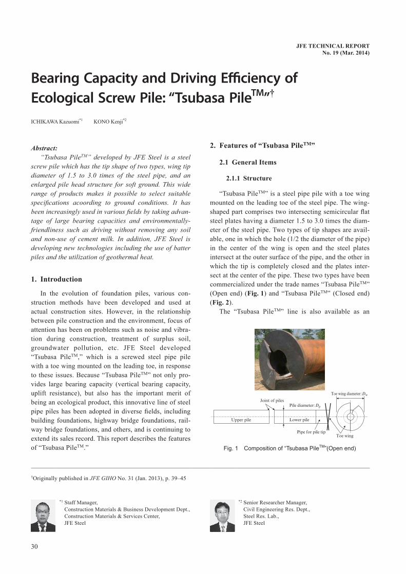
“Tsubasa PileTM” is a steel pipe pile with a toe wing mounted on the leading toe of the steel pipe. The wing-shaped part comprises two intersecting semicircular flat steel plates having a diameter 1.5 to 3.0 times the diam-eter of the steel pipe. Two types of tip shapes are avail-able, one in which the hole (1/2 the diameter of the pipe) in the center of the wing is open and the steel plates intersect at the outer surface of the pipe, and the other in which the tip is completely closed and the plates inter-sect at the center of the pipe. These two types have been commercialized under the trade names “Tsubasa PileTM” (Open end) (Fig.1) and “Tsubasa PileTM” (Closed end) (Fig.2).
The “Tsubasa PileTM” line is also available as an
JFETECHNICALREPORTNo.19(Mar.2014)
Bearing Capacity and Driving Efficiency of Ecological Screw Pile: “Tsubasa PileTM”†
ICHIKAWA Kazuomi*1 KONO Kenji*2
†Originally published in JFE GIHO No. 31 (Jan. 2013), p. 39–45
*1 Staff Manager, Construction Materials & Business Development Dept., Construction Materials & Services Center, JFE Steel
*2 Senior Researcher Manager, Civil Engineering Res. Dept., Steel Res. Lab., JFE Steel
Fig. 1 Composition of “Tsubasa PileTM”(Open end)
JFETECHNICALREPORTNo.19(Mar.2014) 31
Bearing Capacity and Driving Efficiency of Ecological Screw Pile: “Tsubasa PileTM”
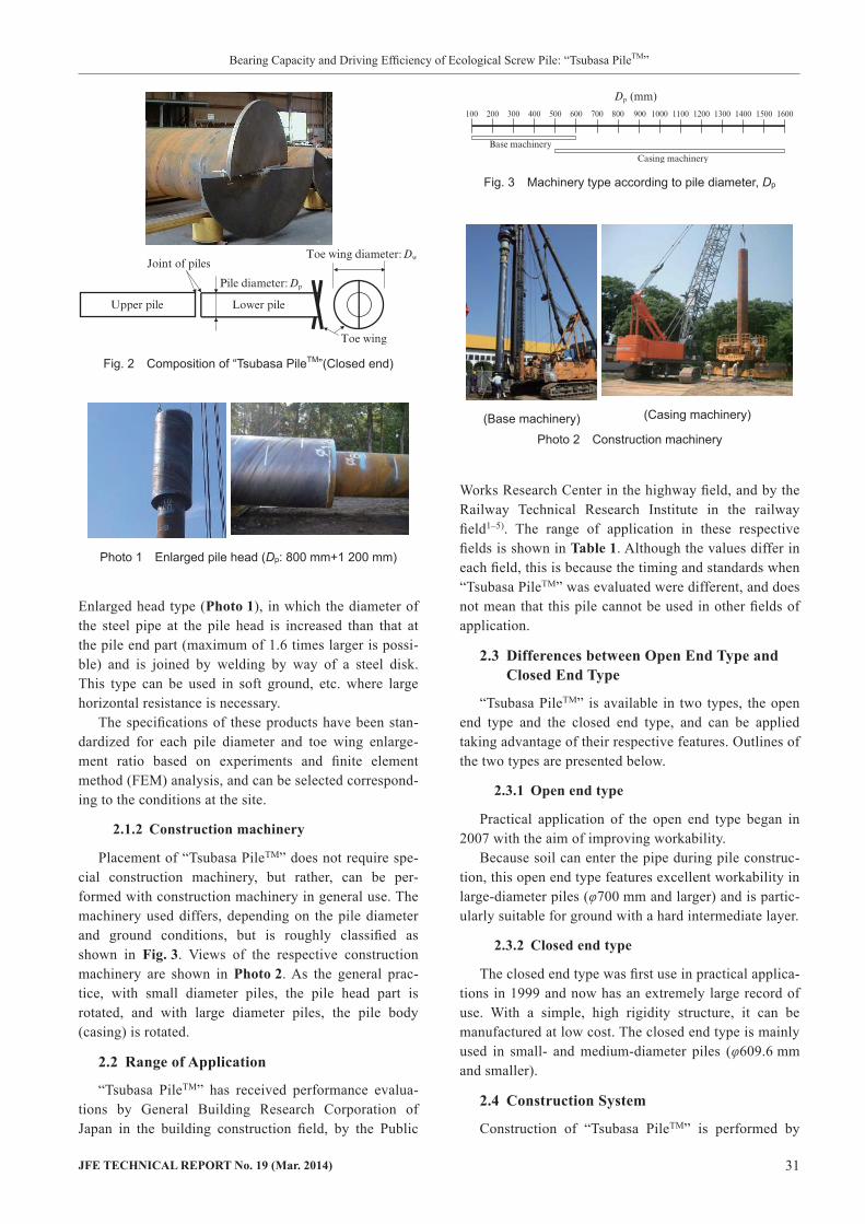
Enlarged head type (Photo1), in which the diameter of the steel pipe at the pile head is increased than that at the pile end part (maximum of 1.6 times larger is possi-ble) and is joined by welding by way of a steel disk. This type can be used in soft ground, etc. where large horizontal resistance is necessary.
The specifications of these products have been stan-dardized for each pile diameter and toe wing enlarge-ment ratio based on experiments and finite element method (FEM) analysis, and can be selected correspond-ing to the conditions at the site.
2.1.2 Constructionmachinery
Placement of “Tsubasa PileTM” does not require spe-cial construction machinery, but rather, can be per-formed with construction machinery in general use. The machinery used differs, depending on the pile diameter and ground conditions, but is roughly classified as shown in Fig.3. Views of the respective construction machinery are shown in Photo2. As the general prac-tice, with small diameter piles, the pile head part is rotated, and with large diameter piles, the pile body (casing) is rotated.
2.2 RangeofApplication
“Tsubasa PileTM” has received performance evalua-tions by General Building Research Corporation of Japan in the building construction field, by the Public
Works Research Center in the highway field, and by the Railway Technical Research Institute in the railway field1–5). The range of application in these respective fields is shown in Table1. Although the values differ in each field, this is because the timing and standards when “Tsubasa PileTM” was evaluated were different, and does not mean that this pile cannot be used in other fields of application.
2.3 DifferencesbetweenOpenEndTypeandClosedEndType
“Tsubasa PileTM” is available in two types, the open end type and the closed end type, and can be applied taking advantage of their respective features. Outlines of the two types are presented below.
2.3.1 Openendtype
Practical application of the open end type began in 2007 with the aim of improving workability.
Because soil can enter the pipe during pile construc-tion, this open end type features excellent workability in large-diameter piles (φ700 mm and larger) and is partic-ularly suitable for ground with a hard intermediate layer.
2.3.2 Closedendtype
The closed end type was first use in practical applica-tions in 1999 and now has an extremely large record of use. With a simple, high rigidity structure, it can be manufactured at low cost. The closed end type is mainly used in small- and medium-diameter piles (φ609.6 mm and smaller).
2.4 ConstructionSystem
Construction of “Tsubasa PileTM” is performed by
Photo 1 Enlarged pile head (Dp: 800 mm+1 200 mm)
Fig. 2 Composition of “Tsubasa PileTM”(Closed end)
Photo 2 Construction machinery
Fig. 3 Machinery type according to pile diameter, Dp
(Base machinery) (Casing machinery)
32 JFETECHNICALREPORTNo.19(Mar.2014)
Bearing Capacity and Driving Efficiency of Ecological Screw Pile: “Tsubasa PileTM”
using general construction machinery. However, special know-how is necessary for reliable construction at diverse construction sites. A “Tsubasa PileTM Technical Society” was organized by JFE Steel and 9 pile con-struction companies (number as of May 2012) and is working to improve technical capabilities.
3. EcologicalConstructionFeatures
3.1 EnvironmentalImpacts
3.1.1 Noearthremovalconstruction
When turning driving force (torque) is applied to “Tsubasa PileTM” at the ground surface, the pile pene-
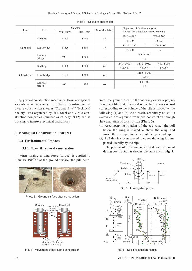
trates the ground because the toe wing exerts a propul-sion effect like that of a wood screw. In this process, soil corresponding to the volume of the pile is moved by the following (1) and (2). As a result, absolutely no soil is excavated aboveground from pile construction through the completion of construction (Photo3).(1) Accompanying rotation of the toe wing, the soil
below the wing is moved to above the wing, and inside the pile pipe, in the case of the open end type.
(2) Soil that has been moved to above the wing is com-pacted laterally by the pipe.
The process of the above-mentioned soil movement during construction is shown schematically in Fig.4.
Table 1 Scope of application
Type FieldDiameter
Max. depth (m) Upper row: Pile diameter (mm) Lower row: Magnification of toe wingMin. (mm) Max. (mm)
Open end
Building 114.3 1 200 87114.3–609.6 700–1 200
1.5–3.0 1.5–2.0
Road bridge 318.5 1 600 77318.5–1 200 1 300–1 600
1.5–2.0 1.5
Railway bridge 400 1 600 ―
400–1 600
1.5
Closed end
Building 114.3 1 200 60114.3–267.4 318.5–508.0 600–1 200
2.0–3.0 2.0–2.5 1.5–2.0
Road bridge 318.5 1 200 60318.5–1 200
1.5–2.0
Railway bridge 400 800 ―
400–800
2.0
Fig. 4 Movement of soil during construction Fig. 6 Soil investigation results
Photo 3 Ground surface after construction
Fig. 5 Investigation points
JFETECHNICALREPORTNo.19(Mar.2014) 33
Bearing Capacity and Driving Efficiency of Ecological Screw Pile: “Tsubasa PileTM”
An example comparing the measured ground density and N-value around the pile before and after construc-tion is shown in Fig.5 and Fig.6. From the fact that density and the N-value increased at points near the pile (A, B) after construction, it can be understood that the ground around the pile undergoes compaction accompa-nied by the pile construction.
As merits of no earth removal construction, not only is the cost of treating surplus soil zero, there is no effect on vehicular traffic in the area because dump trucks are not necessary for disposal of the soil, and construction is also possible at former factory sites, etc., where the ground may be affected by soil pollution.
3.1.2 Nouseofcementmilk
In order to realize a large toe bearing capacity, the general practice with conventional piles requires con-struction of foot protection bulb in the support layer, and in the case of cast-in-place piles, the full length of the pile is constructed of concrete. In either case, pollution of the groundwater by cement milk is unavoidable.
However, with “Tsubasa PileTM,” absolutely no cement milk is required because the toe bearing capacity is supplied by the rigidity of the toe wing itself. There-fore, piles can be constructed without polluting the groundwater, and construction is possible in areas that use well water and areas where river bed water or con-fined (artesian) water exists.
3.1.3 Lownoise/lowvibration
Because “Tsubasa PileTM” is constructed by screwing a steel pipe into the ground, low noise/low vibration construction is possible, without generating the loud
impact noise associated with conventional pile-driving. Figure7 shows the results of measurements of noise and vibration (4 sites) during actual pile construction. In all cases, it can be understood that the values are sub-stantially lower than the limit values (noise: 85 dB, vibration: 75 dB).
3.2 DevelopmenttoNewApplications
With the closed end type, added value can be given to ordinary support piles by utilizing the space inside the pipe after construction is completed. The following are actual examples of value-added applications.
3.2.1 Geothermalheatutilizationair-conditioningsystem
The temperature in the ground is almost constant throughout the year, being lower than atmospheric tem-perature in summer and higher in winter. Efficient air-conditioning is possible if geothermal heat can be used as a heat source for a heat pump system. However, the high cost of installing such systems, for example, the cost of excavation, etc., is an issue. A geothermal heat utilization air-conditioning system which greatly reduces installation costs is possible by using “Tsubasa PileTM” as both a foundation pile and a pile with a heat-exchange function. A schematic diagram is shown in Fig.8.
3.2.2 Treatmentofsurplussoilfromconstruction
At construction sites, generation of surplus soil from various processes other than pile construction is possi-ble. If this surplus soil is placed inside “Tsubasa PileTM” after pile construction, disposal is possible without dis-charging the surplus soil off-site. This can significantly reduce soil transportation and treatment costs.
4. BearingCapacityPerformanceof“TsubasaPileTM”
An extremely large toe bearing capacity can be expected with “Tsubasa PileTM” because bearing capac-ity is supplied by the surface area of the toe wing, which has a diameter 1.5 to 3.0 times that of the pile pipe. Bearing capacity performance comprises two types,
Fig. 7 Measurement of noise and vibration
Fig. 8 Geothermal air-conditioning system
34 JFETECHNICALREPORTNo.19(Mar.2014)
Bearing Capacity and Driving Efficiency of Ecological Screw Pile: “Tsubasa PileTM”
namely, vertical bearing capacity (compressive load) and uplift resistance (tensile load). These two types of bearing capacity are confirmed by large-scale load tests, respectively. However, because the standards differ depending on the field of application, the equations used in evaluations also differ. Since the highway field (open end type, closed end type) and the railway field (open end type) use similar construction methods, a unified bearing capacity equation has been proposed as “screwed steel pipe pile”6,7).
4.1 VerticalBearingCapacity(CompressiveLoad)
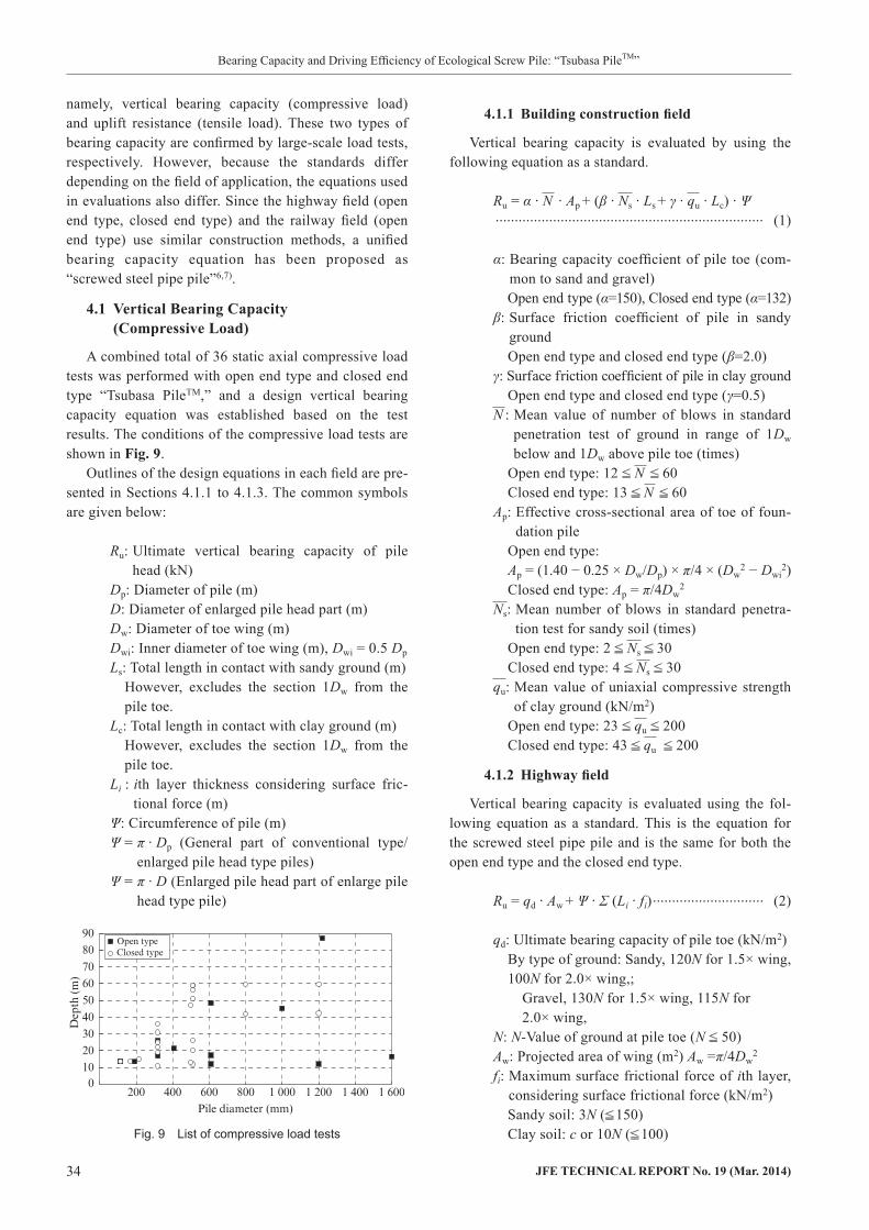
A combined total of 36 static axial compressive load tests was performed with open end type and closed end type “Tsubasa PileTM,” and a design vertical bearing capacity equation was established based on the test results. The conditions of the compressive load tests are shown in Fig.9.
Outlines of the design equations in each field are pre-sented in Sections 4.1.1 to 4.1.3. The common symbols are given below:
Ru: Ultimate vertical bearing capacity of pile head (kN)
Dp: Diameter of pile (m)D: Diameter of enlarged pile head part (m)Dw: Diameter of toe wing (m)Dwi: Inner diameter of toe wing (m), Dwi = 0.5 Dp
Ls: Total length in contact with sandy ground (m)However, excludes the section 1Dw from the pile toe.
Lc: Total length in contact with clay ground (m)However, excludes the section 1Dw from the pile toe.
Li : ith layer thickness considering surface fric-tional force (m)
Ψ: Circumference of pile (m)Ψ = π · Dp (General part of conventional type/
enlarged pile head type piles)Ψ = π · D (Enlarged pile head part of enlarge pile
head type pile)
4.1.1 Buildingconstructionfield
Vertical bearing capacity is evaluated by using the following equation as a standard.
Ru = α · N · Ap + (β · Ns · Ls + γ · qu · Lc) · Ψ ...................................................................... (1)
α: Bearing capacity coefficient of pile toe (com-mon to sand and gravel)Open end type (α=150), Closed end type (α=132)
β: Surface friction coefficient of pile in sandy groundOpen end type and closed end type (β=2.0)
γ: Surface friction coefficient of pile in clay groundOpen end type and closed end type (γ=0.5)
N : Mean value of number of blows in standard penetration test of ground in range of 1Dw below and 1Dw above pile toe (times)
Open end type: 12 N 60Closed end type: 13 N 60
Ap: Effective cross-sectional area of toe of foun-dation pile
Open end type:Ap = (1.40 − 0.25 × Dw/Dp) × π/4 × (Dw
2 − Dwi2)
Closed end type: Ap = π/4Dw2
Ns: Mean number of blows in standard penetra-tion test for sandy soil (times)
Open end type: 2 Ns 30Closed end type: 4 Ns 30
qu: Mean value of uniaxial compressive strength of clay ground (kN/m2)
Open end type: 23 qu 200Closed end type: 43 qu 200
4.1.2 Highwayfield
Vertical bearing capacity is evaluated using the fol-lowing equation as a standard. This is the equation for the screwed steel pipe pile and is the same for both the open end type and the closed end type.
Ru = qd · Aw + Ψ · Σ (Li · fi) ............................. (2)
qd: Ultimate bearing capacity of pile toe (kN/m2)By type of ground: Sandy, 120N for 1.5× wing, 100N for 2.0× wing,;
Gravel, 130N for 1.5× wing, 115N for 2.0× wing,
N: N-Value of ground at pile toe (N 50)Aw: Projected area of wing (m2) Aw =π/4Dw
2
fi: Maximum surface frictional force of ith layer, considering surface frictional force (kN/m2)Sandy soil: 3N ( 150)Clay soil: c or 10N ( 100)Fig. 9 List of compressive load tests

JFETECHNICALREPORTNo.19(Mar.2014) 35
Bearing Capacity and Driving Efficiency of Ecological Screw Pile: “Tsubasa PileTM”
c: Viscosity (kN/m2)N: N-Value of ground at pile surface
4.1.3 Railwayfield
Vertical bearing capacity is evaluated using the fol-lowing equation as a standard. For the open end type, this is the equation for the screwed steel pipe pile.
Ru = qtk · At + Ψ · Σrfk · Li .............................. (3)
qtk: Standard bearing capacity of pile toe (kN/m2)(Open end type) 150N ( 10 000) (Common for sand and gravel)N: Minimum N-value of the section 1Dp above
and 3Dp below pile toe(Closed end type) sand: 75N ( 6 000),Gravel: 75N ( 7 500)
N: N-Value in vicinity of pile toeAt: Area of pile toe (m2)
Open end type:At = π/4 × (Dw
2 − Dwi2)
Closed end type: At = π/4Dw2
rfk: Standard surface bearing capacity (kN/m2)(Open end type) Sandy soil: 2.5N ( 100),Clay soil: 5N ( 100) or 0.3c ( 100)(Closed end type) Sandy soil: 2N ( 100),Clay soil: 4N ( 100)N: N-Value of ground at pile surface, c: Viscosity
(kN/m2)
4.2 UpliftResistance(TensileLoad)
A combined total of 10 tensile load tests was per-formed with the open end type and closed end type of “Tsubasa PileTM.” A design uplift resistance equation was established based on the results of these tests. The conditions of the tensile load tests are shown in Fig.10.
Outlines of the design equations in the respective fields are presented in Sections 4.2.1 to 4.2.3. The com-mon symbols are as follows:
Rt: Ultimate uplift resistance of pile head (kN)Dp: Diameter of pile (m)D: Diameter of enlarged pile head part (m)Dw: Diameter of toe wing (m)Ls: Total length in contact with sandy ground (m)
However, excludes the section 2Dw from the pile toe.
Lc: Total length in contact with clay ground (m)However, excludes the section 2Dw from the pile toe.
Ψ: Circumference of pile (m)Ψ = π · Dp (General part of conventional type/Enlarged pile head type piles)Ψ = π · D (Enlarged pile head part of enlarge
pile head type pile)
γi: Effective unit weight of soil of ith layer from ground surface higher than support layer
(kN/m3)Li: Thickness of ith layer from ground surface
higher than support layer (m)γ: Effective unit weight of soil of support layer
(kN/m3)H: Penetration depth to height that the local shear
fracture region extends above the wing (m)Assuming H 2.5Dw (Highway field)Assuming H 1Dw (Railway field)
β: Uplift coefficient. Expresses the coefficient of resistance of the shear fracture plane; A value corresponding to the internal friction angle of the support layer is applied (Table2).
φ : Internal friction angle of support layer ( ° )
4.2.1 Buildingconstructionfield
Uplift resistance is evaluated using the following equation as a standard. This equation is the same for the open end type and the closed end type.
Rt = κ · Nt · Atp + (λ · Ns · Ls + μ · qu · Lc) · Ψ ...................................................................... (4)
Fig. 10 List of tensile load tests
Table 2 Uplift coefficient, b
Internal friction angle of support layer, φ Uplift coefficient, β
35° 2.16
36° 2.40
37° 2.65
38° 2.89
39° 3.14
40° 3.38
41° 3.77
42° 4.16
43° 4.55
44° 4.93
45° 5.30
36 JFETECHNICALREPORTNo.19(Mar.2014)
Bearing Capacity and Driving Efficiency of Ecological Screw Pile: “Tsubasa PileTM”
κ: Bearing capacity coefficient of pile toe (com-mon to sand and gravel)κ = 63 (0.114 3 Dp 0.609 6)κ = 44 (0.7 Dp 1.2)
λ: Surface frictional force coefficient of pile in sandy groundλ= 0.05 (0.114 3 Dp 0.609 6)λ = 0.03 (0.7 Dp 1.2)
μ: Surface frictional force coefficient of pile in clay groundμ = 1.02 (0.114 3 Dp 0.609 6)μ = 0.71 (0.7 Dp 1.2)
Nt: Mean value of the number of blows in stan-dard penetration test of ground in range of 2Dw above pile toe (times)
12 Nt 60Atp: Area of protruding toe wing (m2)
Atp = π/4 × (Dw2 − Dwi
2)Ns: Mean value of the number of blows in stan-
dard penetration test of sandy ground (times)6 Ns 30
qu: Mean value of uniaxial compressive strength of clay ground (kN/m2)
50 qu 200
4.2.2 Highwayfield
Uplift resistance is evaluated using the following equation as a standard. This equation is the same for the open end type and the closed end type.
Rt = π · Dw · (Σγi · Li + γ · H/2) · H · β · tan φ + Ψ · Σ (Li · fi) ........................................................................... (5)
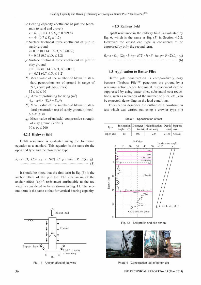
It should be noted that the first term in Eq. (5) is the anchor effect of the pile toe. The mechanism of the anchor effect (uplift resistance) attributable to the toe wing is considered to be as shown in Fig.11. The sec-ond term is the same at that for vertical bearing capacity.
4.2.3 Railwayfield
Uplift resistance in the railway field is evaluated by Eq. 6, which is the same as Eq. (5) in Section 4.2.2. However, the closed end type is considered to be expressed by only the second term.
Rt = π · Dw · (Σγi · Li + γ · H/2) · H · β · tan φ + Ψ · Σ (Li · rfk) ............................................................................ (6)
4.3 ApplicationtoBatterPiles
Batter pile construction is comparatively easy because “Tsubasa PileTM” penetrates the ground by a screwing action. Since horizontal displacement can be suppressed by using batter piles, substantial cost reduc-tions, such as reduction of the number of piles, etc., can be expected, depending on the load conditions.
This section describes the outline of a construction test which was carried out using a crawler type pile
Table 3 Specification of test
Type Inclination angle (°)
Diameter (mm)
Magnification of toe wing
Depth (m)
Support layer
Open end 15 600 2.0 21.51 Gravel
Photo 4 Construction test of batter plie
Fig. 12 Soil profile and pile shape
Fig. 11 Anchor effect of toe wing
JFETECHNICALREPORTNo.19(Mar.2014) 37
Bearing Capacity and Driving Efficiency of Ecological Screw Pile: “Tsubasa PileTM”
PileTM” already has a record of application in actual con-struction by this method.
5. Conclusion
This report described the features of “Tsubasa PileTM,” centering on environmental aspects and bearing capacity. Although “Tsubasa PileTM” has a construction record which already exceeds 500 projects, the authors will continue to work to increase these results in the future.
References
1) Minister of Land, Infrastructure and Transport authorization TACP-0413, “Tsubasa Pile (Open end)” attached document.
2) Minister of Land, Infrastructure and Transport authorization TACP-0395, “Tsubasa Pile (Closed end)” attached document.
3) Public Works Research Center. Consruction Technology Review and Certification “Tsubasa Pile (Open end).” no. 1013, 2011-03.
4) Public Works Research Center. Consruction Technology Review and Certification “Tsubasa Pile (Closed end).” no. 0104, 2011-08.
5) Railway Technical Research Institute. Evaluation of bearing capacity of “Tsubasa Pile.” 2008-03.
6) Japan Road Association. Specification For Highway Bridges. 2012-03.
7) Railway Technical Research Institute. Design Standards of Rail-way Structures and Commentary. 2012-01.
driver, which is a general type of construction machin-ery. Piles up to approximately φ600 mm were con-structed. The test conditions are shown in Table3, the soil profile and pile shape are shown in Fig.12, and views of the construction test are shown in Photo4.
In this test, the control target value of the inclination angle was set at 15° ±0.5°, and piles were placed while measuring the angle periodically.
The results of measurements are shown in Table4. A nearly constant angle was maintained during construc-tion, confirming the applicability of “Tsubasa PileTM” to batter piles. Similar construction is also possible with whole circumference rotary machines, and “Tsubasa
Table 4 Measurement of inclination angle
Depth (m)Inclination angle (°)
Direction of slope Direction of perpendicular to slope
0.0 15.0 0.4
7.25 15.0 ―
9.87 15.0 0.2
9.87 15.0 0.5
15.00 15.0 0.2
21.51 15.2 0.0


![Foundation Technologies for Offshore Deep Water ... - ULisboa · Foundation Technologies for Offshore Deep Water ... A.2.3 Total bearing capacity ... Driving hammer [16] ...](https://static.fdocuments.us/doc/165x107/5d44991088c993243e8e1e8a/foundation-technologies-for-offshore-deep-water-ulisboa-foundation-technologies.jpg)