Spherical Roller Bearings and Spherical Roller Thrust Bearings
Pillow Blocks
Spherical Units
Takeups
Bearing Catalog
... Since 1890

Jones Bearing Company is a manufacturing and marketing company with plants based in the USA. Jones is a part of a group ofcompanies that manufactures and sells mechanical power transmission components and conveyor systems.
Jones has extensive engineering, manufacturing and marketing expertise in the field of mechanical power transmission andconveying equipment. In addition to roller bearing pillow blocks, Jones manufactures flange blocks, take ups, elevator boot bearingassemblies, pulley shaft and conveyor shaft assemblies. The past experience gained as a total manufacturer for the powertransmission and conveying industries is essential for the development and application of a premier product line for general industry.
2000 SeriesPillow Blocks
• High Quality USA Made Spherical Roller Bearings
• Internal Misalignment
• Triple Labyrinth Seal
• Collar Mounted
• Interchanges with Most Major Brands
PB1000 Extra Heavy Duty Pillow Blocks
• Heaviest Production Pillow Block
• Dual Tapered Roller Bearings
• All Steel High Temperature Seals
• Adapter Sleeve Mounted
• Highest Load Ratings Available

Jones is a full-line manufacturer of mounted spherical roller bearings and standard and heavyduty takeups. This catalog includes many of our industry standard designs.
If you cannot find the takeup or bearing unit you require in this catalog, call Jones. We are flexi-ble and will engineer the component you require to meet your most exacting specifications.
Contents
Heavy Duty Spherical UnitsPg. 7
Takeup BlocksJT-2000/JT-5000 Pg. 6
Extra Heavy Duty Pillow BlocksPB-1000 Pg. 16
Extra Heavy DutyProtected Screw Takeups
JPS-3800 Pg. 14
I-FrameHeavy Duty Takeups
JHS-B22500H Pg. 15
Pillow Block Takeup FramesType TFT Pg. 12
Protected Screw Takeup AssembliesJNT-2000 Pg. 11
Rigid Sleeve Bearing TakeupsJSB-2800 Pg. 13
Compensating Foot TakeupsType CU Pg. 10
Normal Duty TakeupsJAT-2000 Pg. 10
Head-End TakeupsJGT-2000/JGT-5000 Pg. 9
Boot-End TakeupsJFT-2000 Pg. 9
Center-Pull TakeupsJHT-2000/JHT-5000 Pg. 8
Piloted Flange Bearings JYRP-2000 Pg. 5
Flanged BearingsJYR-2000 Pg. 4
Pillow BlocksJA-2000 Pg. 2
1
Pillow BlocksJE-2000 Pg. 3

2
Pillow Blocks (2-Bolt)JA-2000
TOTAL BSHAFT ASSEMBLY WEIGHT
min. max.F
DIA. DESIGNATION LBS. A C D E F G bolt Ø
17⁄16 JA2107 7.6 67⁄8 411⁄16 55⁄16 13⁄16 17⁄8 37⁄8 21⁄8 13⁄4 1⁄211⁄2 JA2108 7.4
111⁄16 JA2111 10.4 73⁄8 53⁄16 513⁄16 15⁄16 21⁄8 41⁄4 21⁄8 17⁄8 1⁄213⁄4 JA2112 10.
115⁄16 JA2115 11.8 83⁄8 515⁄16 69⁄16 13⁄ 21⁄4 45⁄8 23⁄8 17⁄8 5⁄82 JA2200 11.6
23⁄16 JA2203 15 87⁄8 67⁄16 71⁄16 15⁄8 21⁄2 5 23⁄8 2 5⁄8
27⁄16 JA2207 20.5 91⁄4 613⁄16 77⁄16 13⁄4 23⁄4 511⁄16 25⁄8 21⁄8 5⁄821⁄2 JA2208 20
211⁄16 JA2211 29.8 101⁄2 713⁄16 87⁄16 21⁄4 31⁄4 67⁄16 25⁄8 23⁄8 3⁄423⁄4 JA2212 29
215⁄16 JA2215 28.23 JA2300 27.4
37⁄16 JA2307 46.5 13 91⁄4 103⁄4 21⁄4 33⁄4 71⁄2 3 25⁄8 7⁄831⁄2 JA2308 45.9
311⁄16 JA2311 70.7 141⁄4 10 113⁄4 21⁄2 41⁄8 87⁄16 33⁄8 3 1315⁄16 JA2315 70.1
4 JA2400 69.5
• Fully self-aligning• Fixed and expansion units
3
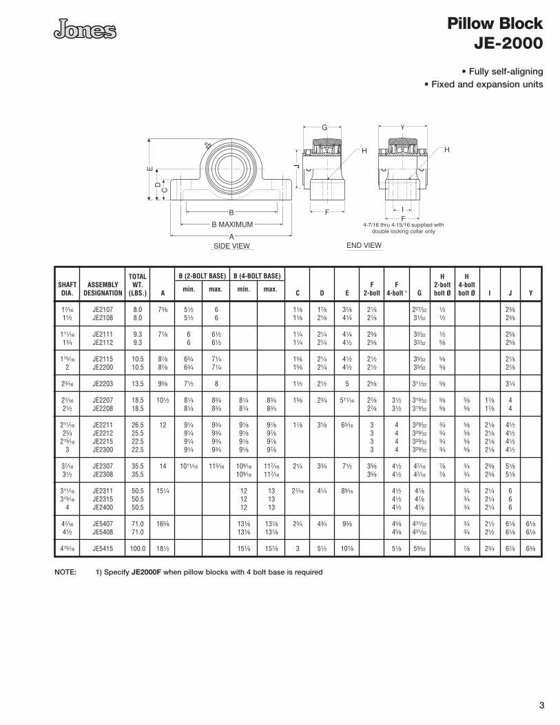
Pillow BlockJE-2000
TOTAL B (2-BOLT BASE) B (4-BOLT BASE) H HSHAFT ASSEMBLY WT.
min. max. min. max.F F 2-bolt 4-bolt
DIA. DESIGNATION (LBS.) A C D E 2-bolt 4-bolt 1 G bolt Ø bolt Ø I J Y
17⁄16 JE2107 8.0 73⁄8 51⁄2 6 11⁄8 17⁄8 37⁄8 21⁄8 227⁄32 1⁄2 23⁄811⁄2 JE2108 8.0 51⁄2 6 11⁄8 21⁄8 41⁄4 21⁄8 31⁄32 1⁄2 23⁄8
111⁄16 JE2111 9.3 77⁄8 6 61⁄2 11⁄4 21⁄4 41⁄4 23⁄8 32⁄32 1⁄2 25⁄813⁄4 JE2112 9.3 6 61⁄2 11⁄4 21⁄4 41⁄2 23⁄8 32⁄32 5⁄8 25⁄8
115⁄16 JE2115 10.5 87⁄8 63⁄4 71⁄4 15⁄6 21⁄4 41⁄2 21⁄2 35⁄32 5⁄8 27⁄82 JE2200 10.5 87⁄8 63⁄4 71⁄4 15⁄6 21⁄4 41⁄2 21⁄2 35⁄32 5⁄8 27⁄8
23⁄16 JE2203 13.5 95⁄8 71⁄2 8 11⁄2 21⁄2 5 25⁄8 311⁄32 5⁄8 31⁄4
27⁄16 JE2207 18.5 101⁄2 81⁄4 83⁄4 81⁄4 83⁄4 15⁄8 23⁄4 511⁄16 27⁄8 31⁄2 319⁄32 5⁄8 5⁄8 17⁄8 421⁄2 JE2208 18.5 81⁄4 83⁄4 81⁄4 83⁄4 27⁄8 31⁄2 319⁄32 5⁄8 5⁄8 17⁄8 4
211⁄16 JE2211 26.5 12 91⁄4 93⁄4 91⁄8 97⁄8 17⁄8 31⁄8 65⁄16 3 4 329⁄32 3⁄4 5⁄8 21⁄8 41⁄223⁄4 JE2212 25.5 91⁄4 93⁄4 91⁄8 97⁄8 3 4 329⁄32 3⁄4 5⁄8 21⁄8 41⁄2
215⁄16 JE2215 22.5 91⁄4 93⁄4 91⁄8 97⁄8 3 4 329⁄32 3⁄4 5⁄8 21⁄8 41⁄23 JE2300 22.5 91⁄4 93⁄4 91⁄8 97⁄8 3 4 329⁄32 3⁄4 5⁄8 21⁄8 41⁄2
37⁄16 JE2307 35.5 14 1011⁄16 115⁄16 109⁄16 117⁄16 21⁄4 33⁄4 71⁄2 35⁄8 41⁄2 47⁄16 7⁄8 3⁄4 23⁄8 51⁄831⁄2 JE2308 35.5 109⁄16 117⁄16 35⁄8 41⁄2 47⁄16 7⁄8 3⁄4 23⁄8 51⁄8
311⁄16 JE2311 50.5 151⁄4 12 13 27⁄16 41⁄4 89⁄16 41⁄2 47⁄8 3⁄4 21⁄4 6315⁄16 JE2315 50.5 12 13 41⁄2 47⁄8 3⁄4 21⁄4 6
4 JE2400 50.5 12 13 41⁄2 47⁄8 3⁄4 21⁄4 6
47⁄16 JE5407 71.0 165⁄8 131⁄8 137⁄8 23⁄4 43⁄4 93⁄8 45⁄8 431⁄32 3⁄4 21⁄2 61⁄8 61⁄841⁄2 JE5408 71.0 131⁄8 137⁄8 45⁄8 431⁄32 3⁄4 21⁄2 61⁄8 61⁄8
415⁄16 JE5415 100.0 181⁄2 151⁄8 157⁄8 3 51⁄2 107⁄8 51⁄8 59⁄32 7⁄8 23⁄4 67⁄8 65⁄8
NOTE: 1) Specify JE2000F when pillow blocks with 4 bolt base is required
• Fully self-aligning• Fixed and expansion units

ASSEMBLY TOTAL E HSHAFT DESIGNATION WEIGHT bolt G +.000DIA. LBS. A B C D circle 1 F bolt Ø – .003
17⁄16 JYR2107 8.45 61⁄4 21⁄8 27⁄8 33⁄4 5 3⁄4 3@1⁄2 3.56211⁄2 JYR2108 8.40
111⁄16 JYR2111 10.5 63⁄4 21⁄8 3 41⁄8 51⁄2 3⁄4 4@1⁄2 4.06213⁄4 JYR2112 10.5
115⁄16 JYR2115 11.0 7 23⁄8 3 41⁄2 53⁄4 3⁄4 4@1⁄2 4.3752 JYR2200 11.0
23⁄16 JYR2203 13.5 73⁄4 23⁄8 31⁄4 51⁄8 63⁄8 3⁄4 4@5⁄8 5.000
27⁄16 JYR2207 17.5 81⁄8 25⁄8 31⁄2 57⁄8 63⁄4 15⁄16 4@5⁄8 5.43721⁄2 JYR2208 17.5
211⁄16 JYR2211 27.00 91⁄2 25⁄8 37⁄8 63⁄8 77⁄8 15⁄16 4@3⁄4 6.31223⁄4 JYR2212 27.00
215⁄16 JYR2215 26.00 3 JYR2300 26.00
37⁄16 JYR2307 38.00 111⁄8 33⁄16 49⁄32 73⁄8 91⁄2 11⁄8 4@3⁄4 7.37531⁄2 JYR2308 38.00
37⁄16 JYR2307S 38.00 87⁄16 33⁄16 49⁄32 73⁄8 91⁄2 11⁄8 4@3⁄4 7.375 31⁄2 JYR2308S 38.00
311⁄16 JYR2311 53.00315⁄16 JYR2315 52.00 125⁄8 33⁄8 427⁄32 83⁄8 103⁄4 11⁄8 4@7⁄8 8.500
4 JRY2400
311⁄16 JYR2311S 53.00315⁄16 JYR2315S 52.00 93⁄4 33⁄8 427⁄32 83⁄8 103⁄4 11⁄8 4@7⁄8 8.500
4 JYR2400(S)
◆
4
Flanged BearingsJYR-2000
NOTES: 1) JYR 1-7⁄16 and 1-1⁄2 only available with three bolt flange all other sizes use four holes evenly spaced.
◆ Pilot - Use suffix P
• Fully self-aligning• Fixed and expansion units
◆
5
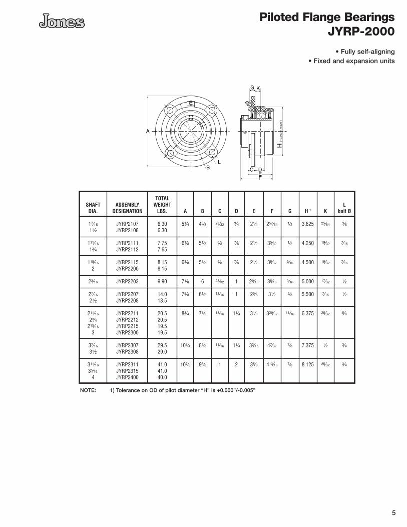
Piloted Flange BearingsJYRP-2000
TOTALSHAFT ASSEMBLY WEIGHT LDIA. DESIGNATION LBS. A B C D E F G H 1 K bolt Ø
17⁄16 JYRP2107 6.30 51⁄4 43⁄8 23⁄32 3⁄4 21⁄4 257⁄64 1⁄2 3.625 25⁄64 3⁄811⁄2 JYRP2108 6.30
111⁄16 JYRP2111 7.75 61⁄8 51⁄8 5⁄8 7⁄8 21⁄2 35⁄32 1⁄2 4.250 19⁄32 7⁄16
13⁄4 JYRP2112 7.65
115⁄16 JYRP2115 8.15 63⁄8 53⁄8 5⁄8 7⁄8 21⁄2 35⁄32 9⁄16 4.500 19⁄32 7⁄16
2 JYRP2200 8.15
23⁄16 JYRP2203 9.90 71⁄8 6 23⁄32 1 29⁄16 35⁄16 9⁄16 5.000 17⁄32 1⁄2
27⁄16 JYRP2207 14.0 75⁄8 61⁄2 13⁄16 1 25⁄8 31⁄2 5⁄8 5.500 7⁄16 1⁄221⁄2 JYRP2208 13.5
211⁄16 JYRP2211 20.5 83⁄4 71⁄2 13⁄16 11⁄4 31⁄8 329⁄32 11⁄16 6.375 25⁄32 5⁄823⁄4 JYRP2212 20.5
215⁄16 JYRP2215 19.53 JYRP2300 19.5
37⁄16 JYRP2307 29.5 101⁄4 85⁄8 11⁄16 11⁄4 33⁄16 47⁄32 7⁄8 7.375 1⁄2 3⁄431⁄2 JYRP2308 29.0
311⁄16 JYRP2311 41.0 107⁄8 93⁄8 1 2 35⁄8 413⁄16 7⁄8 8.125 25⁄32 3⁄435⁄16 JYRP2315 41.0
4 JYRP2400 40.0
NOTE: 1) Tolerance on OD of pilot diameter “H” is +0.000”/-0.005”
• Fully self-aligning• Fixed and expansion units
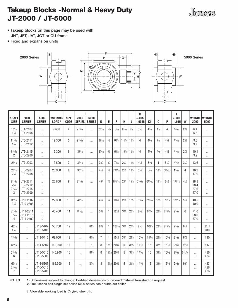
C K TSHAFT 2000 5000 WORKING SIZE 2000 5000 +.005 +.005 WEIGHT WEIGHTSIZE SERIES SERIES LOAD † CODE SERIES SERIES D E F H J -.0015 K1 O P -.015 W 2000 5000
17⁄16 JT4-2107 ... 7,600 4 213⁄16 ... 27⁄16 11⁄16 53⁄8 17⁄16 7⁄8 31⁄2 41⁄8 5⁄8 4 17⁄32 23⁄8 6.4 ...11⁄2 JT4-2108 ... 6.3 ...
111⁄16 JT5-2111 ... 12,300 5 215⁄16 ... 35⁄16 5⁄8 61⁄8 115⁄16 11⁄8 4 43⁄4 3⁄4 45⁄8 11⁄16 25⁄8 9.8 ...13⁄4 JT5-2112 ... 9.7 ...
115⁄16 JT6-2115 ... 12,300 6 31⁄16 ... 35⁄16 5⁄8 61⁄8 115⁄16 11⁄8 4 43⁄4 3⁄4 45⁄8 11⁄16 27⁄8 10.1 ...2 JT6-2200 ... 9.9 ...
23⁄16 JT7-2203 ... 13,500 7 33⁄16 ... 33⁄4 3⁄4 71⁄8 21⁄4 11⁄4 41⁄2 51⁄4 1 51⁄4 13⁄16 31⁄4 13.6 ...
27⁄16 JT8-2207 ... 20,900 8 37⁄16 ... 41⁄8 7⁄8 731⁄32 21⁄2 13⁄8 51⁄8 57⁄8 11⁄4 525⁄32 11⁄16 4 18.2 ...21⁄2 JT8-2208 ... 17.9 ...
211⁄16 JT9-2211 ... 26,800 9 311⁄16 ... 43⁄4 7⁄8 815⁄16 23⁄4 15⁄8 515⁄16 611⁄16 11⁄4 61⁄2 113⁄16 41⁄2 28.8 ...23⁄4 JT9-2212 ... 28.4 ...
215⁄16 JT9-2215 ... 27.6 ...3 JT9-2300 ... 27.0 ...
37⁄16 JT10-2307 ... 27,300 10 43⁄32 ... 47⁄8 7⁄8 101⁄4 27⁄8 17⁄8 613⁄16 713⁄16 15⁄8 79⁄16 113⁄16 51⁄8 40.5 ...31⁄2 JT10-2308 ... 40.0 ...
311⁄16 JT11-2311 ... 45,400 11 421⁄32 ... 53⁄8 1 121⁄8 33⁄8 21⁄8 85⁄8 97⁄16 21⁄8 813⁄16 21⁄16 6 71.0 ...315⁄16 JT11-2315 ... 68.0 ...
4 JT11-2400 ... 67.0 ...
47⁄16 ... JT12-5407 53,700 12 ... 61⁄8 63⁄8 1 137⁄16 33⁄8 21⁄8 91⁄2 103⁄8 21⁄8 913⁄16 21⁄16 61⁄8 ... 91.141⁄2 ... JT12-5408 ... 90.0
415⁄16 ... JT13-5415 68,000 13 ... 65⁄8 7 1 151⁄8 33⁄4 23⁄8 101⁄4 111⁄4 21⁄2 107⁄8 21⁄16 67⁄8 ... 130
57⁄16 ... JT14-5507 140,900 14 ... 8 8 11⁄32 205⁄8 5 31⁄8 141⁄8 16 31⁄2 153⁄8 29⁄16 83⁄16 ... 417
515⁄16 ... JT15-5515 140,900 15 ... 81⁄8 8 15⁄32 205⁄8 5 31⁄8 141⁄8 16 31⁄2 153⁄8 29⁄16 811⁄16 ... 4266 ... JT15-5600 ... 424
67⁄16 ... JT16-5607 165,300 16 ... 83⁄4 8 19⁄32 205⁄8 5 31⁄8 141⁄8 16 31⁄2 153⁄8 29⁄16 93⁄4 ... 433615⁄16 ... JT16-5615 ... 428
7 ... JT16-5700 ... 426
6
Takeup Blocks -Normal & Heavy Duty JT-2000 / JT-5000
• Takeup blocks on this page may be used withJHT, JFT, JAT, JGT or CU frame
• Fixed and expansion units
NOTES: 1) Dimensions subject to change. Certified dimensions of ordered material furnished on request.2) 2000 series has single set collar. 5000 series has double set collar.
† Allowable working load is 2/3 yield strength.
2000 Series 5000 Series
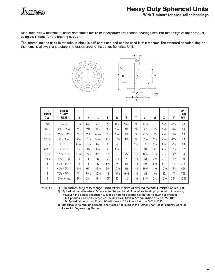
STD. OTHER SPH.SHAFT SHAFT UNITDIA. SIZES † J K L P R S T V * W X Y WT.
115⁄16 113⁄16 - 2 115⁄16 23⁄16 41⁄8 3 25⁄16 33⁄16 7⁄8 411⁄16 1 31⁄2 47⁄16 10
23⁄16 213⁄16 - 21⁄4 21⁄16 23⁄8 47⁄16 33⁄8 25⁄8 33⁄8 7⁄8 51⁄8 11⁄16 33⁄4 47⁄8 13
27⁄16 25⁄16 - 21⁄2 25⁄16 25⁄8 415⁄16 35⁄8 27⁄8 35⁄8 7⁄8 511⁄16 13⁄16 41⁄4 53⁄8 18
215⁄16 25⁄8 - 27⁄8 25⁄8 31⁄16 511⁄16 41⁄8 37⁄16 41⁄8 7⁄8 69⁄16 13⁄8 47⁄8 63⁄16 28
37⁄16 3 - 31⁄2 215⁄16 37⁄16 63⁄8 5 4 5 11⁄8 8 13⁄4 51⁄2 75⁄8 48
315⁄16 35⁄8 - 4 43⁄8 43⁄8 83⁄4 6 63⁄4 6 11⁄8 10 2 63⁄4 95⁄8 92
47⁄16 41⁄8 - 41⁄2 411⁄16 411⁄16 93⁄8 63⁄4 7 63⁄8 11⁄8 103⁄4 21⁄4 71⁄4 101⁄4 130
415⁄16 45⁄8 - 415⁄16 5 5 10 7 73⁄4 7 11⁄8 12 21⁄2 73⁄4 113⁄8 170
6 57⁄16 - 515⁄16 6 6 12 85⁄8 9 85⁄8 13⁄8 15 31⁄2 91⁄4 14 340
7 67⁄16 - 615⁄16 63⁄4 63⁄4 131⁄2 93⁄4 101⁄2 91⁄2 13⁄8 163⁄4 41⁄4 103⁄4 151⁄2 560
8 77⁄16 - 715⁄16 79⁄16 79⁄16 151⁄8 11 113⁄4 105⁄8 13⁄8 19 43⁄4 12 173⁄4 785
9 87⁄8 - 815⁄16 89⁄16 89⁄16 171⁄8 121⁄4 13 12 13⁄8 213⁄4 51⁄2 131⁄2 201⁄4 1003
7
Heavy Duty Spherical UnitsWith Timken® tapered roller bearings
Manufacturers & machine builders sometimes desire to incorporate anti-friction bearing units into the design of their product,using their frame for the bearing support.
The internal unit as used in the takeup block is self-contained and can be used in this manner. The standard spherical ring onthe housing allows manufacturers to design around the Jones Spherical Unit.
NOTES: 1) †Dimensions subject to change. Certified dimensions of ordered material furnished on request.2) *Spherical unit diameters “V” are noted in fractional dimensions to simplify construction work;
however, the actual dimension would be held to decimal having the following tolerances:A) Spherical unit sizes 1-15/16” -7” inclusive will have a “V” dimension of +.000”/-.001”.B) Spherical unit sizes 8” and 9” will have a “V” dimension of +.000”/-.002”.
3) Spherical units requiring special shaft sizes not listed in the ‘Other Shaft Sizes’ column, consult Jones for Engineering Review.
115⁄16 JHT6-2115- 12 JHT6- 12 58 12,300 315⁄16 271⁄2 115⁄16 291⁄2 4 7⁄8 ... 83⁄16 151⁄2 63⁄8 2 5⁄8 732 JHT6-2200- 18 18 69 331⁄2 351⁄2 211⁄2 84
24 24 80 391⁄2 411⁄2 271⁄2 9530 30 91 451⁄2 471⁄2 331⁄2 10636 36 102 511⁄2 531⁄2 391⁄2 117
12 JHT7- 12 67 13,000 47⁄16 271⁄2 21⁄16 291⁄2 4 13⁄16 ... 9 15 63⁄4 2 5⁄8 8523⁄16 JHT7-2203- 18 18 78 331⁄2 351⁄2 21 96
24 24 90 391⁄2 411⁄2 27 10830 30 101 451⁄2 471⁄2 33 11936 36 112 511⁄2 531⁄2 39 130
27⁄16 JHT8-2207- 12 JHT8- 12 74 16,300 43⁄8 281⁄2 23⁄16 301⁄2 4 3⁄4 ... 93⁄16 15 71⁄2 2 3⁄4 9821⁄2 JHT8-2208- 18 18 86 341⁄2 361⁄2 21 110
24 24 98 401⁄2 421⁄2 27 12230 30 110 461⁄2 481⁄2 33 13436 36 122 521⁄2 541⁄2 39 146
12 JHT9- 12 115 26,800 51⁄8 301⁄2 27⁄16 321⁄2 5 11⁄8 2 107⁄8 16 81⁄8 4 5⁄8 145211⁄16 JHT9-2211- 18 18 131 361⁄2 381⁄2 22 161215⁄16 JHT9-2215- 24 24 145 421⁄2 441⁄2 28 175
3 JHT9-2300- 30 30 165 481⁄2 501⁄2 34 19536 36 182 541⁄2 561⁄2 40 202
12 JHT10- 12 126 27,300 55⁄8 32 25⁄8 341⁄4 5 11⁄8 2 1113⁄16 16 83⁄4 4 3⁄4 16137⁄16 JHT10-2307-18 18 145 38 401⁄4 22 18031⁄2 JHT10-2308-24 24 164 44 461⁄4 28 199
30 30 183 50 521⁄4 34 21836 36 202 56 581⁄4 40 237
311⁄16 JHT11-2311-12 JHT11- 12 195 38,400 7 36 3 381⁄2 6 13⁄8 21⁄2 143⁄8 171⁄2 105⁄8 4 3⁄4 244315⁄16 JHT11-2315-18 18 227 42 441⁄2 231⁄2 276
4 JHT11-2400-24 24 253 48 501⁄2 281⁄2 30230 30 278 54 561⁄2 351⁄2 32736 36 304 60 621⁄2 401⁄2 353
47⁄16 JHT12-5408-12 JHT12- 12 279 53,3000 71⁄2 403⁄4 31⁄16 453⁄4 87⁄8 13⁄8 5 151⁄2 19 121⁄4 4 11⁄8 36341⁄2 JHT12-5407-18 18 307 463⁄4 513⁄4 25 391
24 24 334 523⁄4 573⁄4 31 41830 30 363 583⁄4 633⁄4 37 44736 36 384 643⁄4 693⁄4 43 46842 42 420 703⁄4 753⁄4 49 504
415⁄16 JHT13-5415-12 JHT13- 12 310 68,000 81⁄8 441⁄2 35⁄16 491⁄2 97⁄8 1 51⁄2 163⁄4 201/4 131⁄2 4 11⁄8 4405 JHT13-5500-18 18 330 501⁄2 551⁄2 261/4 460
24 24 365 561⁄2 611⁄2 321/4 49630 30 397 621⁄2 671⁄2 381/4 52736 36 425 681⁄2 731⁄2 441/4 55542 42 457 741⁄2 791⁄2 501/4 587
57⁄16 JHT14-5507-18 JHT14- 18 876 136,700 109⁄16 55 4 61 12 11⁄2 7 221⁄2 18 231⁄2 4 13⁄4 129330 30 1003 67 73 30 142042 42 1130 79 85 42 1547
515⁄16 JHT15-5515-18 JHT15- 18 878 136,700 109⁄16 55 41⁄16 61 12 11⁄2 7 221⁄2 18 231⁄2 4 13⁄4 13006 JHT15-5600-30 30 995 67 73 30 1427
42 42 1121 79 85 42 1547
67⁄16 JHT16-5607-18 JHT16- 18 876 136,700 109⁄16 55 43⁄8 61 12 11⁄2 7 221⁄2 18 231⁄2 4 13⁄4 1304615⁄16 JHT16-5615-30 30 1003 67 73 30 1431
7 JHT16-6700-42 42 1130 79 85 42 1558
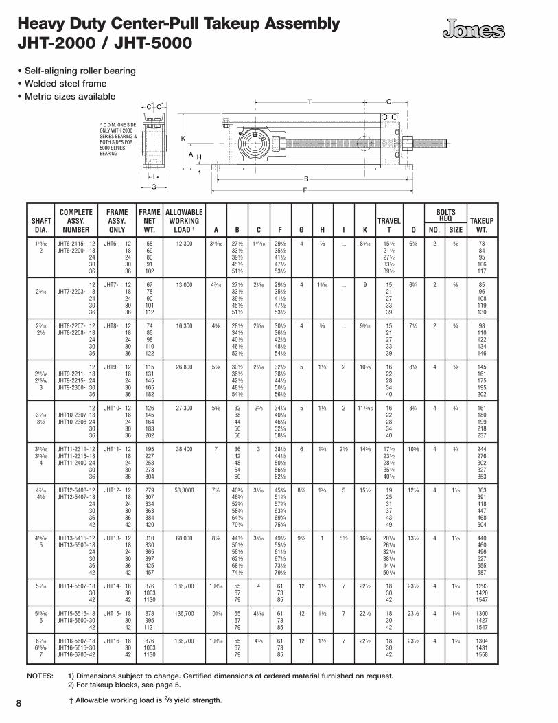
COMPLETE FRAME FRAME ALLOWABLE BOLTSSHAFT ASSY. ASSY. NET WORKING TRAVEL REQ TAKEUPDIA. NUMBER ONLY WT. LOAD † A B C F G H I K T O NO. SIZE WT.
8
Heavy Duty Center-Pull Takeup Assembly JHT-2000 / JHT-5000
• Self-aligning roller bearing• Welded steel frame• Metric sizes available
NOTES: 1) Dimensions subject to change. Certified dimensions of ordered material furnished on request.2) For takeup blocks, see page 5.
† Allowable working load is 2/3 yield strength.
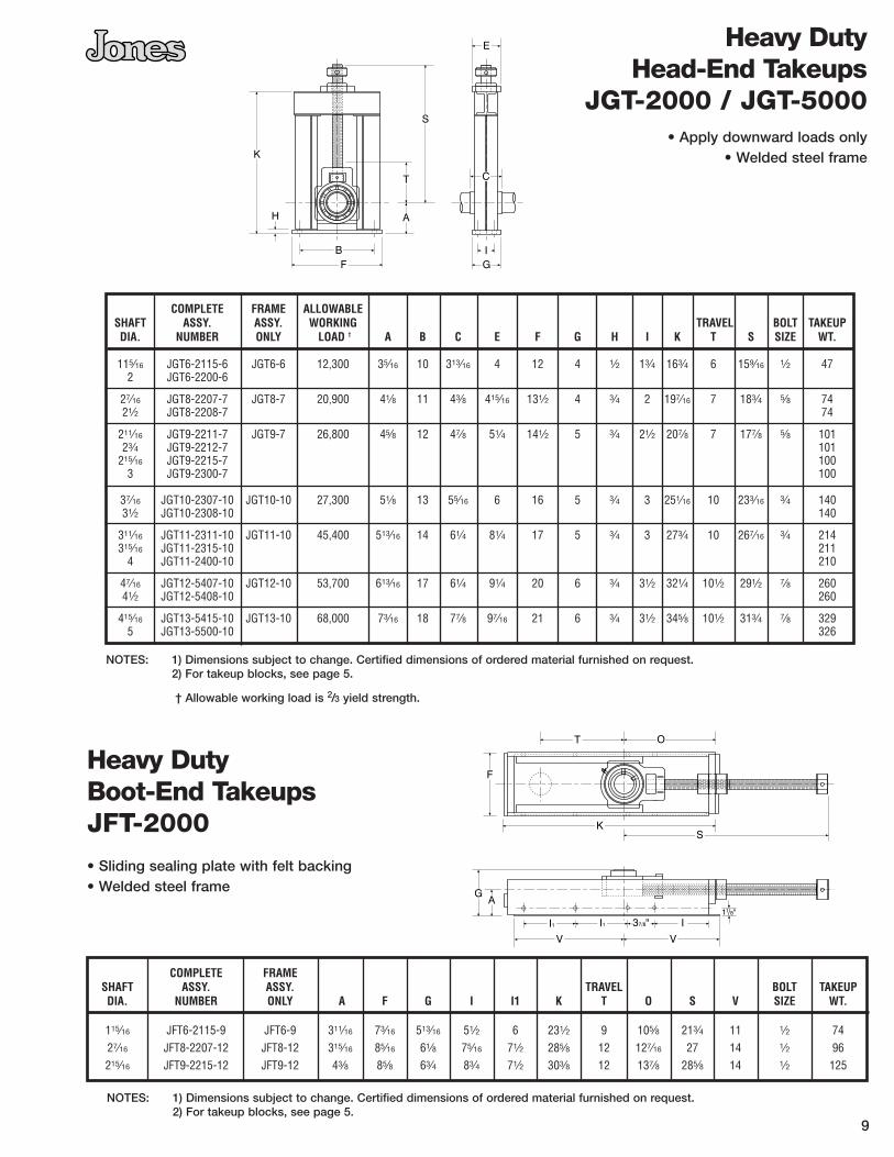
COMPLETE FRAMESHAFT ASSY. ASSY. TRAVEL BOLT TAKEUPDIA. NUMBER ONLY A F G I I1 K T O S V SIZE WT.
115⁄16 JFT6-2115-9 JFT6-9 311⁄16 73⁄16 513⁄16 51⁄2 6 231⁄2 9 105⁄8 213⁄4 11 1⁄2 7427⁄16 JFT8-2207-12 JFT8-12 315⁄16 85⁄16 61⁄8 75⁄16 71⁄2 285⁄8 12 127⁄16 27 14 1⁄2 96215⁄16 JFT9-2215-12 JFT9-12 43⁄8 85⁄8 63⁄4 83⁄4 71⁄2 303⁄8 12 137⁄8 285⁄8 14 1⁄2 125
COMPLETE FRAME ALLOWABLESHAFT ASSY. ASSY. WORKING TRAVEL BOLT TAKEUPDIA. NUMBER ONLY LOAD † A B C E F G H I K T S SIZE WT.
115⁄16 JGT6-2115-6 JGT6-6 12,300 35⁄16 10 313⁄16 4 12 4 1⁄2 13⁄4 163⁄4 6 159⁄16 1⁄2 472 JGT6-2200-6
27⁄16 JGT8-2207-7 JGT8-7 20,900 41⁄8 11 43⁄8 415⁄16 131⁄2 4 3⁄4 2 197⁄16 7 183⁄4 5⁄8 7421⁄2 JGT8-2208-7 74
211⁄16 JGT9-2211-7 JGT9-7 26,800 45⁄8 12 47⁄8 51⁄4 141⁄2 5 3⁄4 21⁄2 207⁄8 7 177⁄8 5⁄8 10123⁄4 JGT9-2212-7 101
215⁄16 JGT9-2215-7 1003 JGT9-2300-7 100
37⁄16 JGT10-2307-10 JGT10-10 27,300 51⁄8 13 55⁄16 6 16 5 3⁄4 3 251⁄16 10 233⁄16 3⁄4 14031⁄2 JGT10-2308-10 140
311⁄16 JGT11-2311-10 JGT11-10 45,400 513⁄16 14 61⁄4 81⁄4 17 5 3⁄4 3 273⁄4 10 267⁄16 3⁄4 214315⁄16 JGT11-2315-10 211
4 JGT11-2400-10 210
47⁄16 JGT12-5407-10 JGT12-10 53,700 613⁄16 17 61⁄4 91⁄4 20 6 3⁄4 31⁄2 321⁄4 101⁄2 291⁄2 7⁄8 26041⁄2 JGT12-5408-10 260
415⁄16 JGT13-5415-10 JGT13-10 68,000 73⁄16 18 77⁄8 97⁄16 21 6 3⁄4 31⁄2 345⁄8 101⁄2 313⁄4 7⁄8 3295 JGT13-5500-10 326
9
Heavy DutyHead-End Takeups
JGT-2000 / JGT-5000• Apply downward loads only
• Welded steel frame
Heavy DutyBoot-End TakeupsJFT-2000
• Sliding sealing plate with felt backing• Welded steel frame
NOTES: 1) Dimensions subject to change. Certified dimensions of ordered material furnished on request.2) For takeup blocks, see page 5.
NOTES: 1) Dimensions subject to change. Certified dimensions of ordered material furnished on request.2) For takeup blocks, see page 5.
† Allowable working load is 2/3 yield strength.

COMPLETE FRAME BOLTSSHAFT ASSY. ASSY. TRAVEL REQ. TAKEUPDIA. NUMBER ONLY A D E F G H I K T N O S NO. SIZE WT.
17⁄16 JAT4-2107-9 JAT4-9 17⁄8 67⁄16 11⁄2 157⁄8 53⁄16 3⁄16 39⁄16 35⁄8 9 3 37⁄8 15 6 1⁄2 18.4
111⁄16 JAT5-2111-9 JAT6-9 2 7 11⁄2 17 513⁄16 1⁄4 41⁄16 37⁄8 9 31⁄4 43⁄4 16 6 1⁄2 26.8
115⁄16 JAT5-2115-9 JAT6-9 2 7 11⁄2 17 513⁄16 1⁄4 41⁄16 37⁄8 9 31⁄4 43⁄4 16 6 1⁄2 27.1
23⁄16 JAT7-2203-9 JAT7-9 2 71⁄2 11⁄2 18 69⁄16 1⁄4 413⁄16 4 9 39⁄16 57⁄16 1615⁄16 6 1⁄2 33.7
27⁄16 JAT8-2207-12 JAT8-12 21⁄4 61⁄16 13⁄4 2111⁄16 75⁄16 15⁄16 51⁄16 47⁄16 12 313⁄16 57⁄8 203⁄4 8 1⁄2 51.0
215⁄16 JAT9-2115-12 JAT9-12 27⁄16 61⁄2 13⁄4 23 81⁄8 5⁄16 53⁄8 47⁄8 12 41⁄4 63⁄4 213⁄4 8 1⁄2 75.0
• Self-aligning roller bearing• Welded steel frame• Economical design
10
Compensating Foot TakeupsType CU• Self-aligning HD roller bearing
• Sleeve bearing available
• Spring loaded
• Welded steel frame
Normal Duty Takeup Assembly
JAT-2000
SHAFTDIA. ADJ. A B C D E F G H L M N P Q R T V W WT.
17⁄16 61⁄8 27⁄8 17⁄8 27⁄8 41⁄2 115⁄16 61⁄2 73⁄4 13⁄4 133⁄4 75⁄8 53⁄8 25⁄8 7⁄16 3⁄8 13⁄4 47⁄8 67⁄8 28
115⁄16 8 31⁄8 129⁄32 31⁄2 53⁄4 143⁄8 71⁄4 87⁄8 21⁄4 181⁄4 101⁄4 61⁄4 213⁄16 7⁄16 1⁄2 21⁄4 61⁄4 91⁄8 45
27⁄16 10 31⁄2 23⁄16 43⁄4 73⁄8 183⁄8 83⁄4 101⁄4 21⁄2 221⁄2 121⁄2 75⁄8 33⁄16 5⁄8 1⁄2 23⁄4 71⁄4 115⁄8 67
215⁄16 12 4 27⁄16 55⁄8 9 223⁄4 101⁄8 117⁄8 31⁄8 271⁄2 151⁄2 81⁄2 35⁄8 5⁄8 5⁄8 31⁄4 97⁄8 131⁄4 111
NOTES: 1) All bearings fitted with 1/8” Alemite button head fittings.2) For takeup blocks, see page 5.
NOTES: 1) Dimensions subject to change. Certified dimensions of ordered material furnished on request.2) For takeup blocks, see page 5.

115⁄16 JNT6-2115- 12 13.0 JNT6- 12 3,000 315⁄16 261⁄2 27⁄8 281⁄2 31⁄2 41⁄8 13⁄4 ... 81⁄4 12 71⁄4 17⁄8 2 5/8 512 JNT6-2200- 18 12.8 18 321⁄2 341⁄2 18 57
24 24 381⁄2 401⁄2 24 6330 30 441⁄2 461⁄2 30 7036 36 501⁄2 521⁄2 36 75
23⁄16 JNT7-2203- 12 17.3 JNT7- 12 3,600 43⁄16 271⁄2 31⁄8 291⁄2 31⁄2 41⁄8 13⁄4 ... 811⁄16 12 73⁄4 2 2 5/8 5718 18 331⁄2 351⁄2 18 6224 24 391⁄2 411⁄2 24 6730 30 451⁄2 471⁄2 30 7236 36 511⁄2 531⁄2 36 77
12 JNT8- 12 4,400 43⁄8 281⁄2 33⁄8 301⁄2 31⁄2 41⁄8 13⁄4 ... 91⁄4 12 81⁄4 21⁄8 2 3/4 6227⁄16 JNT8-2007- 18 21.4 18 341⁄2 361⁄2 18 6721⁄2 JNT8-2208- 24 21.1 24 401⁄2 421⁄2 24 72
30 30 461⁄2 481⁄2 30 7736 36 521⁄2 541⁄2 36 82
211⁄16 JNT9-2211- 12 31.0 JNT9- 12 6,800 51⁄8 301⁄2 35⁄8 321⁄2 41⁄2 51⁄8 2 2 1013⁄16 12 91⁄4 23⁄8 4 3/4 10023⁄4 JNT9-2212- 18 30.6 18 361⁄2 381⁄2 18 109
215⁄16 JNT9-2215- 24 29.8 24 421⁄2 441⁄2 24 1193 JNT9-2300- 30 29.2 30 481⁄2 501⁄2 30 128
36 36 541⁄2 561⁄2 36 136
12 JNT10- 12 8,400 55⁄8 32 41⁄32 341⁄4 41⁄2 55⁄8 2 2 127⁄16 12 10 219⁄32 4 3/4 12337⁄16 JNT10-2307- 18 44.0 18 38 401⁄4 18 13231⁄2 JNT10-2308- 24 43.5 24 44 461⁄4 24 142
30 30 50 521⁄4 30 15136 36 56 581⁄4 36 159
311⁄16 JNT11-2311- 12 85.0 JNT11- 12 15,600 7 36 419⁄32 381⁄2 51⁄2 67⁄8 21⁄4 21⁄2 145⁄8 12 12 231⁄32 4 3/4 215315⁄16 JNT11-2315- 18 83.0 18 42 441⁄2 18 226
4 JNT11-2400- 24 82.0 24 48 501⁄2 24 23830 30 54 561⁄2 30 24936 36 60 621⁄2 36 261
COMPLETE FRAME ALLOWABLE REQ. BOLTS TOTALSHAFT ASSY. BLOCK ASSY. WORKING TRAVEL WT.SIZE NUMBER WT. NUMBER LOAD † A B C F G G1 H I K T O Q NO. SIZE LBS.
11
Protected Screw Takeup Assembly JNT-2000
• 2000 Series roller bearing• Normal duty rating
• Welded steel frame
NOTES: 1) Dimensions subject to change. Certified dimensions of ordered material furnished on request.
† Allowable working load is 2/3 yield strength.
{ {{ {
{ {{ {{ {{ {
F
J
I
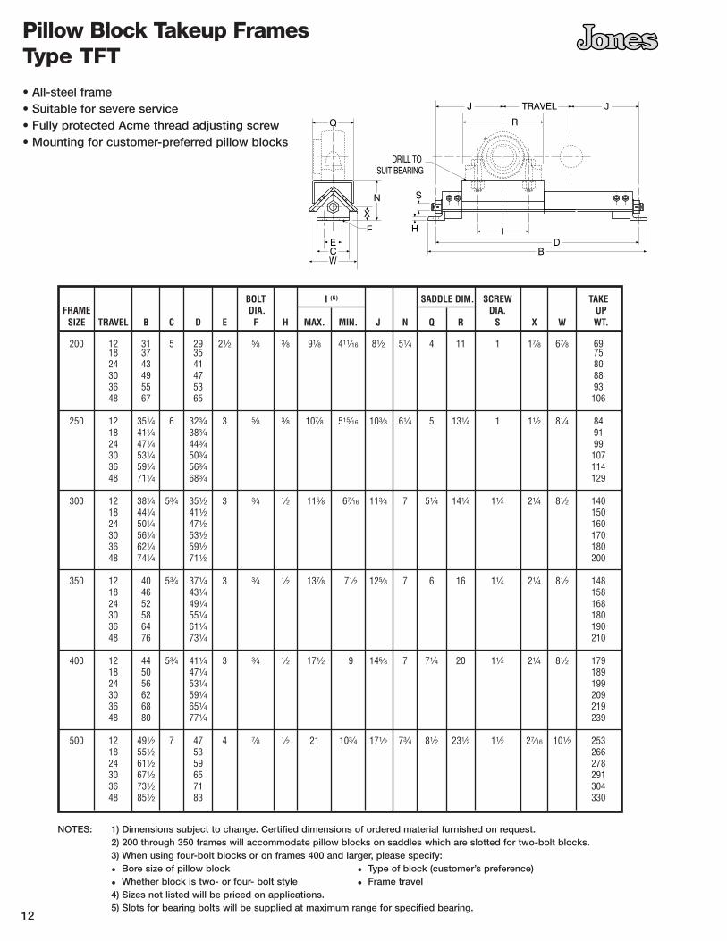
BOLT I (5) SADDLE DIM. SCREW TAKEFRAME DIA. DIA. UP
SIZE TRAVEL B C D E F H MAX. MIN. J N Q R S X W WT.
200 12 31 5 29 21⁄2 5⁄8 3⁄8 91⁄8 411⁄16 81⁄2 51⁄4 4 11 1 17⁄8 67⁄8 6918 37 35 7524 43 41 8030 49 47 8836 55 53 9348 67 65 106
250 12 351⁄4 6 323⁄4 3 5⁄8 3⁄8 107⁄8 515⁄16 103⁄8 61⁄4 5 131⁄4 1 11⁄2 81⁄4 8418 411⁄4 383⁄4 9124 471⁄4 443⁄4 9930 531⁄4 503⁄4 10736 591⁄4 563⁄4 11448 711⁄4 683⁄4 129
300 12 381⁄4 53⁄4 351⁄2 3 3⁄4 1⁄2 115⁄8 67⁄16 113⁄4 7 51⁄4 141⁄4 11⁄4 21⁄4 81⁄2 14018 441⁄4 411⁄2 15024 501⁄4 471⁄2 16030 561⁄4 531⁄2 17036 621⁄4 591⁄2 18048 741⁄4 711⁄2 200
350 12 40 53⁄4 371⁄4 3 3⁄4 1⁄2 137⁄8 71⁄2 125⁄8 7 6 16 11⁄4 21⁄4 81⁄2 14818 46 431⁄4 15824 52 491⁄4 16830 58 551⁄4 18036 64 611⁄4 19048 76 731⁄4 210
400 12 44 53⁄4 411⁄4 3 3⁄4 1⁄2 171⁄2 9 145⁄8 7 71⁄4 20 11⁄4 21⁄4 81⁄2 17918 50 471⁄4 18924 56 531⁄4 19930 62 591⁄4 20936 68 651⁄4 21948 80 771⁄4 239
500 12 491⁄2 7 47 4 7⁄8 1⁄2 21 103⁄4 171⁄2 73⁄4 81⁄2 231⁄2 11⁄2 27⁄16 101⁄2 25318 551⁄2 53 26624 611⁄2 59 27830 671⁄2 65 29136 731⁄2 71 30448 851⁄2 83 330
NOTES: 1) Dimensions subject to change. Certified dimensions of ordered material furnished on request.2) 200 through 350 frames will accommodate pillow blocks on saddles which are slotted for two-bolt blocks.3) When using four-bolt blocks or on frames 400 and larger, please specify:
• Bore size of pillow block • Type of block (customer’s preference)
• Whether block is two- or four- bolt style • Frame travel4) Sizes not listed will be priced on applications.5) Slots for bearing bolts will be supplied at maximum range for specified bearing.
12
Pillow Block Takeup Frames Type TFT
• All-steel frame• Suitable for severe service• Fully protected Acme thread adjusting screw• Mounting for customer-preferred pillow blocks

13
SHAFT TAKEUP BOLTSDIA. ADJ.* NO. A B C D E F G H K L X
115⁄16 12 JSB-2831-12 31⁄4 261⁄2 291⁄2 4 3 5⁄8 ... 13⁄4 73⁄4 71⁄4 1⁄418 JSB-2831-18 321⁄2 351⁄2
23⁄16 12 JSB-2835-12 33/8 271⁄2 291⁄2 4 3 5⁄8 ... 13⁄4 73⁄4 71⁄4 3⁄818 JSB-2835-18 331⁄2 351⁄2
27⁄16 12 JSB-2839-12 31⁄2 281⁄2 301⁄2 5 3 3⁄4 ... 13⁄4 81⁄4 71⁄2 3⁄818 JSB-2839-18 341⁄2 361⁄224 JSB-2839-24 401⁄2 421⁄2
215⁄16 12 JSB-2847-12 41⁄8 301⁄2 321⁄2 6 4 5⁄8 2 2 91⁄4 83⁄4 3⁄818 JSB-2847-18 361⁄2 381⁄224 JSB-2847-24 421⁄2 441⁄2
37⁄16 12 JSB-2855-12 41⁄2 32 341⁄4 7 4 3⁄4 2 2 10 911⁄16 1⁄218 JSB-2855-18 38 401⁄424 JSB-2855-24 44 461⁄4
315⁄16 12 JSB-2863-12 5 36 381⁄2 8 5 3⁄4 21⁄2 21⁄4 12 1015⁄16 1⁄218 JSB-2863-18 42 441⁄224 JSB-2863-24 48 501⁄2
Rigid Sleeve Bearing TakeupsJSB-2800
• Hinged or removable top frame• Protected screw• Babbitt bearing
• Bronze bearing available• Relubricatable
NOTES: 1) Dimensions subject to change. Certified dimensions of ordered material furnished on request.2) One pipe-tapped hole for lubrication. Grease cup or lubrication fitting not included.3) * Takeups with adjustment of 18” or more have center supported pad welded to bottom of frame.4) Allowable working load is 2/3 yield strength.
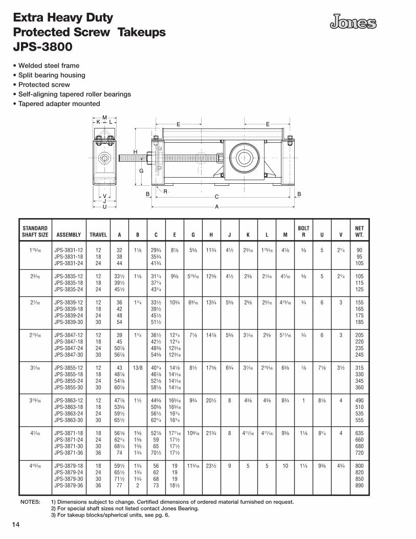
STANDARD BOLT NETSHAFT SIZE ASSEMBLY TRAVEL A B C E G H J K L M R U V WT.
115⁄16 JPS-3831-12 12 32 11⁄8 293⁄4 87⁄8 55⁄8 113⁄4 41⁄2 23⁄16 115⁄16 41⁄8 5⁄8 5 21⁄4 90JPS-3831-18 18 38 353⁄4 95JPS-3831-24 24 44 413⁄4 105
23⁄16 JPS-3835-12 12 331⁄2 11⁄8 311⁄4 95⁄8 515⁄16 123⁄8 41⁄2 23⁄8 21⁄16 47⁄16 5⁄8 5 21⁄4 105JPS-3835-18 18 391⁄2 371⁄4 115JPS-3835-24 24 451⁄2 431⁄4 125
27⁄16 JPS-3839-12 12 36 11⁄4 331⁄2 103⁄4 69⁄16 133⁄4 55⁄8 25⁄8 25⁄16 415⁄16 3⁄4 6 3 155JPS-3839-18 18 42 391⁄2 165JPS-3839-24 24 48 451⁄2 175JPS-3839-30 30 54 511⁄2 185
215⁄16 JPS-3847-12 12 39 11⁄4 361⁄2 121⁄4 71⁄8 147⁄8 55⁄8 31⁄16 25⁄8 511⁄16 3⁄4 6 3 205JPS-3847-18 18 45 421⁄2 121⁄4 220JPS-3847-24 24 507⁄8 483⁄8 123⁄16 235JPS-3847-30 30 567⁄8 543⁄8 123⁄16 245
37⁄16 JPS-3855-12 12 43 13/8 401⁄4 141⁄8 81⁄2 175⁄8 63⁄4 37⁄16 215⁄16 63⁄8 7⁄8 71⁄8 31⁄2 315JPS-3855-18 18 487⁄8 461⁄8 141⁄16 330JPS-3855-24 24 547⁄8 521⁄8 141⁄16 345JPS-3855-30 30 607⁄8 581⁄8 141⁄16 360
315⁄16 JPS-3863-12 12 477⁄8 11⁄2 445⁄8 165⁄16 93⁄4 201⁄2 8 43⁄8 43⁄8 83⁄4 1 81⁄8 4 490JPS-3863-18 18 535⁄8 505⁄8 165⁄16 510JPS-3863-24 24 591⁄2 561⁄2 161⁄4 535JPS-3863-30 30 651⁄2 621⁄4 161⁄4 555
47⁄16 JPS-3871-18 18 561⁄8 15⁄8 527⁄8 177⁄16 109⁄16 213⁄4 8 411⁄16 411⁄16 93⁄8 11⁄8 81⁄4 4 635JPS-3871-24 24 621⁄4 15⁄8 59 171⁄2 660JPS-3871-30 30 681⁄4 15⁄8 65 171⁄2 680JPS-3871-36 36 74 13⁄4 701⁄2 171⁄2 720
415⁄16 JPS-3879-18 18 591⁄2 13⁄4 56 19 115⁄16 231⁄2 9 5 5 10 11⁄4 93⁄8 43⁄4 800JPS-3879-24 24 651⁄2 13⁄4 62 19 820JPS-3879-30 30 711⁄2 13⁄4 68 19 850JPS-3879-36 36 77 2 73 181⁄2 890
14
Extra Heavy Duty Protected Screw TakeupsJPS-3800• Welded steel frame• Split bearing housing• Protected screw• Self-aligning tapered roller bearings• Tapered adapter mounted
NOTES: 1) Dimensions subject to change. Certified dimensions of ordered material furnished on request.2) For special shaft sizes not listed contact Jones Bearing.3) For takeup blocks/spherical units, see pg. 6.
15
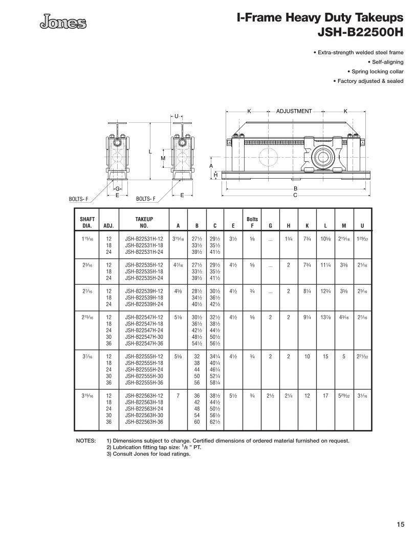
SHAFT TAKEUP BoltsDIA. ADJ. NO. A B C E F G H K L M U
115⁄16 12 JSH-B22531H-12 315⁄16 271⁄2 291⁄2 31⁄2 5⁄8 ... 13⁄4 73⁄4 105⁄8 215⁄16 129⁄32
18 JSH-B22531H-18 331⁄2 351⁄224 JSH-B22531H-24 391⁄2 411⁄2
23⁄16 12 JSH-B22535H-12 47⁄16 271⁄2 291⁄2 41⁄2 5⁄8 ... 2 73⁄4 111⁄4 33⁄8 21⁄16
18 JSH-B22535H-18 331⁄2 351⁄224 JSH-B22535H-24 391⁄2 411⁄2
27⁄16 12 JSH-B22539H-12 45⁄8 281⁄2 301⁄2 41⁄2 3⁄4 ... 2 81⁄4 123⁄4 35⁄8 23⁄16
18 JSH-B22539H-18 341⁄2 361⁄224 JSH-B22539H-24 401⁄2 421⁄2
215⁄16 12 JSH-B22547H-12 51⁄8 301⁄2 321⁄2 41⁄2 5⁄8 2 2 91⁄4 137⁄8 43⁄16 27⁄16
18 JSH-B22547H-18 361⁄2 381⁄224 JSH-B22547H-24 421⁄2 441⁄230 JSH-B22547H-30 481⁄2 501⁄236 JSH-B22547H-36 541⁄2 561⁄2
37⁄16 12 JSH-B22555H-12 55⁄8 32 341⁄4 41⁄2 3⁄4 2 2 10 15 5 221⁄32
18 JSH-B22555H-18 38 401⁄424 JSH-B22555H-24 44 461⁄430 JSH-B22555H-30 50 521⁄436 JSH-B22555H-36 56 581⁄4
315⁄16 12 JSH-B22563H-12 7 36 381⁄2 51⁄2 3⁄4 21⁄2 21⁄4 12 17 529⁄32 31⁄16
18 JSH-B22563H-18 42 441⁄224 JSH-B22563H-24 48 501⁄230 JSH-B22563H-30 54 561⁄236 JSH-B22563H-36 60 621⁄2
I-Frame Heavy Duty Takeups JSH-B22500H
• Extra-strength welded steel frame
• Self-aligning
• Spring locking collar
• Factory adjusted & sealed
NOTES: 1) Dimensions subject to change. Certified dimensions of ordered material furnished on request.2) Lubrication fitting tap size: 1/8 ” PT.3) Consult Jones for load ratings.

16
STD. OTHER E++ SLOTTED DRILLED G APROX.SHAFT SHAFT CORED HOLES HOLES (2) (4) NET WGT.SIZE SIZES † A B C D MIN MAX ▲ F BOLTS BOLTS H J K L M N O P R S LBS.
115⁄16 113⁄16-2 27⁄8 111⁄2 31⁄4 11⁄8 87⁄8 97⁄8 93⁄8 — 3⁄4 — 65⁄8 115⁄16 23⁄16 41⁄8 11⁄2 6 1⁄2 3 25⁄16 57⁄8 30
23⁄16 21⁄16-21⁄4 31⁄8 121⁄2 31⁄2 11⁄4 91⁄2 101⁄2 10 — 5⁄8 — 71⁄8 21⁄16 23⁄8 47⁄16 15⁄8 61⁄2 1⁄2 33⁄8 25⁄8 63⁄4 40
27⁄16 25⁄8-27⁄8 4 141⁄4 37⁄8 13⁄8 103⁄4 121⁄4 113⁄8 21⁄4 — 5⁄8 85⁄16 25⁄16 25⁄8 415⁄16 13⁄4 71⁄4 5⁄8 35⁄8 27⁄8 73⁄16 53
215⁄16 21⁄16-21⁄4 43⁄4 151⁄2 43⁄8 11⁄2 113⁄4 131⁄4 121⁄2 23⁄4 — 5⁄8 95⁄8 25⁄8 31⁄16 511⁄16 2 81⁄8 5⁄8 41⁄8 37⁄16 715⁄16 79
37⁄16 3-31⁄2 51⁄2 17 51⁄4 15⁄8 13 141⁄2 133⁄4 31⁄4 — 3⁄4 115⁄16 215⁄16 37⁄16 63⁄8 23⁄8 91⁄2 3⁄4 5 4 911⁄16 124
315⁄16 35⁄8-4 63⁄8 20 61⁄4 17⁄8 51⁄2 171⁄4 163⁄8 31⁄4 — 7⁄8 135⁄16 43⁄8 43⁄8 83⁄4 27⁄8 111⁄2 3⁄4 6 63⁄4 113⁄16 220
47⁄16 41⁄8-41⁄2 71⁄4 22 61⁄2 21⁄8 161⁄2 181⁄2 171⁄2 31⁄2 — 1 1411⁄16 411⁄16 411⁄16 93⁄8 3 123⁄8 7⁄8 63⁄4 7 121⁄16 290
415⁄16 45⁄8-5 71⁄2 241⁄2 7 21⁄4 183⁄4 203⁄4 193⁄4 33⁄4 — 11⁄8 153⁄4 5 5 10 31⁄4 14 7⁄8 7 73⁄4 133⁄8 365
6 57⁄16-515⁄16 10 35 81⁄4 23⁄4 273⁄4 301⁄4 29 41⁄2 — 11⁄4 203⁄8 6 6 12 37⁄8 171⁄2 11⁄8 85⁄8 9 171⁄4 690
7 67⁄16-615⁄16 111⁄2 39 93⁄4 31⁄4 301⁄2 331⁄2 32 51⁄2 — 11⁄2 231⁄16 63⁄4 63⁄4 131⁄2 45⁄8 191⁄2 11⁄4 93⁄4 101⁄2 197⁄16 1125
8 77⁄16-715⁄16 13 44 111⁄4 35⁄8 341⁄4 373⁄4 36 61⁄2 — 13⁄8 26 79⁄16 79⁄16 151⁄8 51⁄4 22 11⁄2 11 113⁄4 223⁄8 1600
9 87⁄16-815⁄16 15 49 13 4 38 42 40 8 — 2 30 89⁄16 89⁄16 171⁄8 6 25 13⁄4 121⁄4 13 265⁄8 2100
Extra Heavy Duty Pillow BlocksPB 1000 Series
• Non-Expansion and Expansion Types
LJ K
M
R P
FC
G - BOLTS
LJ K
M
R P
C
O - BOLTS
BE
H
D
A
S
N
NOTES: 1) Specify Non-Expansion or Expansion type Pillow Blocks on all orders.2) Pillow Blocks are normally supplied with slotted cored base bolt holes unless the order specifically states
standard drill holes. See E++ Above3) Pillow Blocks ordered with drilled base bolt holes will be drilled for the same size bolts shown in the table
above and will be located by dimension “E” & “F” as noted above. See symbol ▲ above.4) Pillow Blocks requiring special shaft sizes not listed in other shaft size columns consult Jones for
Engineering review. See † symbol above.
To order, specify Jones 1000 Series & Shaft Size: e.g. 315/16 Dia. Specify: PB1000 - 315/16

Self Alignment is independent of the roller bearing, occurring between the spherical unit and the pillow blockhousing. Alignment occurs as the spherical unit pivots or slides in the pillow block housing on the machinedspherical ring of the spherical housing. This design maintains gaps or labyrinths between the seals and thehousing under all conditions of operation, permitting them to be positively sealed with grease.
The outer housing is a two piece design made of sturdy and generously proportioned cast iron. The housing isdesigned for heavy duty service utilizing a solid casting with no cored sections in the mounting feet to weakenthe bearing support. The cap & base are machined as a matched unit to assure close tolerance and precise fitof the spherical unit in the straight bore (expansion type) or the spherical bore (non-expansion type). The twopiece construction permits easy removal of the spherical bearing unit and shaft without changing thealignment position.
The Timken Tapered Roller Bearings are factory sealed in the spherical unit at the time of assembly and neednot be disassembled on the jobsite at the time of installation.
The mounting base is solid under the mounting bolts for a rigid support and is generously proportioned sothat a dowel pin may be used if necessary. The slotted, cored base bolt holes simplify mounting and permitmaximum lateral adjustment. Cored base holes are standard, but drilled base holes (optional) are available ifdesired.
The hydraulic type grease fitting mounted in a bushing is fully protected from dust, dirt and possible damageby a spring type dust cap.
User Benefits
Expansion Pillow Block
Non-Expansion Pillow Block
Section through an Expansion Type Pillow Blockshowing the straight bore in the cap and base. Thisdesign is used in the adaptor for bearings with shaftdiameters of 115⁄16” to 37⁄16” inclusive.
Spherical unit
Used in either block
Section through a spherical unit. Note how the spheri-cal ring will fit in either the straight bore of the expan-sion type pillow block Housing or in the mating spher-ical ring bore of the non-expansion type pillow blockhousing.
Section through a Non-Expansion Type Pillow Blockwith a spherical bore in the cap and base. This adap-tor design with a backing off nut is used for the bear-ings with shaft diameters of 315⁄16” to 9” inclusive.

P.O. Box 274 Highway 72 East Pelham, Alabama 35124 USA
phone: 205-663-3002 fax: 205-664-3351