BEAMS, HEADERS, AND COLUMNS WESTER N CANA DA
20
WESTERN CANADA BEAMS, HEADERS, AND COLUMNS Featuring Trus Joist ® TimberStrand ® LSL, Microllam ® LVL, and Parallam ® PSL • Uniform and Predictable • Minimal Bowing, Twisting, and Shrinking • Strong and Straight • Limited Product Warranty #TJ-9505 SPECIFIER’S GUIDE
Transcript of BEAMS, HEADERS, AND COLUMNS WESTER N CANA DA

WESTERNCANADA
BEAMS, HEADERS, AND COLUMNSFeaturing Trus Joist® TimberStrand® LSL, Microllam® LVL, and Parallam® PSL
• Uniform and Predictable
• Minimal Bowing, Twisting, and Shrinking
• Strong and Straight
• Limited Product Warranty
#TJ-9505 SPECIFIER’S GUIDE

The products in this guide are readily available through our nationwide network of distributors and dealers. For more information on other applications or other Trus Joist® products, contact your Weyerhaeuser representative.
This guide is for use with NBCC 2010, NBCC 2015, CSA O86-09 and CSA O86-14.
Using advanced technology, Weyerhaeuser manufactures engineered lumber that is consistently straight and strong, and that resists bowing, twisting, and shrinking.That means less waste, easier installation, and higher design values for starters; plus fewer callbacks, shorter cycle times, more design flexibility, and lower overall installed cost in the end. Trus Joist® TimberStrand® LSL, Microllam® LVL, and Parallam® PSL are structural solutions you can count on—guaranteed.
Grades shown are available in Western Canada; some sizes may not be available in your region.
Why Choose Trus Joist® Beams, Columns, and Headers?
• Reliable performance
• Consistent quality and dependable uniformity
• Flexible solutions for your beam and header needs
• Backed by a limited product warranty
For deeper depth Parallam® PSL beams, see the Trus Joist® 2.2E Parallam® PSL Deep Beam Technical Resource Sheet, #TJ-7501, or contact your Weyerhaeuser representative.
TABLE OF CONTENTS
2Trus Joist® Beam, Header, and Column Specifier’s Guide (W. Canada) TJ-9505 | March 2020
General Assumptions 3Design Properties 4Floor and/or Snow Load Tables
TimberStrand® LSL 5Microllam® LVL 6–7Parallam® PSL 8–9
Beam Details 10Window and Door Header Details 10–11Nailing on Narrow Face 11Allowable Holes 12Bearing Length Requirements 12Tapered End Cuts 13Multiple-Member Connections 14–16Header Design Example Problem 16Parallam® PSL Columns 17Product Warranty 20
This guide features Trus Joist® engineered lumber in the following widths and depths:
TimberStrand® LSL
1.55E TimberStrand® LSL header and beam sizes: Widths: 1¾" and 3½" Depths: 9½", 117⁄8", 14", and 16"
Microllam® LVL
2.0E Microllam® LVL header and beam sizes: Width: 1¾" Depths: 5½", 7¼", 9¼", 9½", 11¼", 117⁄8", 14", 16", 18", and 20"
Parallam® PSL
2.2E Parallam® PSL header and beam sizes: Widths: 3½", 5¼", and 7" Depths: 9¼", 9½", 11¼", 117⁄8", 14", 16", and 19"1.8E Parallam® PSL column and post sizes: 31⁄2" x 31⁄2" 31⁄2" x 51⁄4" 31⁄2" x 7" 51⁄4" x 51⁄4" 51⁄4" x 7" 7" x 7"
®
®
® ®
Protect product from sun and water
CAUTION: Wrap is slippery when wet or icy
PRODUCT STORAGE
Use support blocks (6x6 or larger) at 10' on-centre to keep bundles out of mud and water
Align stickers (2x3 or larger) directly over support blocks

3Trus Joist® Beam, Header, and Column Specifier’s Guide (W. Canada) TJ-9505 | March 2020
STRUCTURAL SOLUTIONS
Trus Joist® TimberStrand® Laminated Strand Lumber (LSL)• One-piece members reduce labor time• Every piece is straight and strong• Unique properties allow you to drill larger holes through
1.55E TimberStrand® LSL. See Allowable Holes on page 12.
Code Evaluations: See CCMC 12627-R
Trus Joist® Parallam® Parallel Strand Lumber (PSL)• Allows long spans for open floor plans without intermediate posts or columns• Has warm, unique grain that is perfect for applications with exposed beams• Provides ideal solutions for cantilever and multi-span applications• Solid sections save time on site assembly
Code Evaluations: See CCMC 11161-R
Trus Joist® Microllam® Laminated Veneer Lumber (LVL)• Can easily be built up on site to reduce heavy lifting• Offers reliable and economical solutions for beam and header applications• Manufacturing process minimizes many of the natural inconsistencies
found in wood
Code Evaluations: See CCMC O8675-R
TimberStrand® LSL, Microllam® LVL, and untreated Parallam® PSL are intended for dry-use applications
• Specified strengths and factored resistances are based on Limit States Design per CSA O86.
• Lateral support is required at bearing and along the span at 24" on-centre, maximum.
• Bearing lengths are based on each product’s bearing resistance for applicable grade and orientation.
• All members 7¼" and less in depth are restricted to a maximum deflection of 5⁄16".
• Beams that are 1¾" x 16" and deeper require multiple plies. Some exceptions allowed when using Weyerhaeuser software.
• No camber.• Beams and columns must remain straight to within 5L2⁄4608 (in.) of
true alignment. L is the unrestrained length of the member in feet.For applications not covered in this guide, contact your Weyerhaeuser representative.See pages 14–16 for multiple-member beam connections.
General Assumptions for Products Shown in this Guide
4Trus Joist® Beam, Header, and Column Specifier’s Guide (W. Canada) TJ-9505 | March 2020
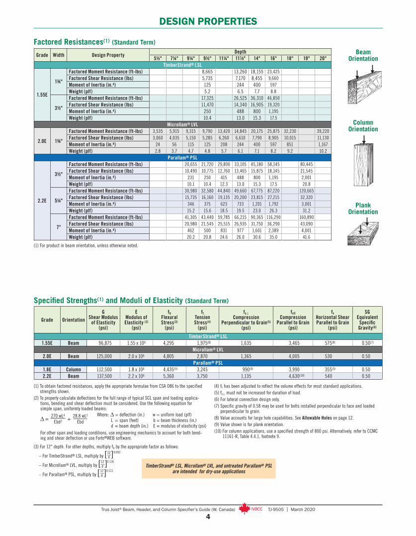
DESIGN PROPERTIES
Grade Width Design PropertyDepth
5½" 7¼" 9¼" 9½" 11¼" 117⁄8" 14" 16" 18" 19" 20"TimberStrand® LSL
1.55E
1¾"
Factored Moment Resistance (ft-lbs) 8,665 13,260 18,155 23,425Factored Shear Resistance (lbs) 5,735 7,170 8,455 9,660Moment of Inertia (in.4) 125 244 400 597Weight (plf) 5.2 6.5 7.7 8.8
3½"
Factored Moment Resistance (ft-lbs) 17,325 26,525 36,310 46,850Factored Shear Resistance (lbs) 11,470 14,340 16,905 19,320Moment of Inertia (in.4) 250 488 800 1,195Weight (plf) 10.4 13.0 15.3 17.5
Microllam® LVL
2.0E 1¾"
Factored Moment Resistance (ft-lbs) 3,535 5,915 9,315 9,790 13,420 14,845 20,175 25,875 32,230 39,220Factored Shear Resistance (lbs) 3,060 4,035 5,150 5,285 6,260 6,610 7,790 8,905 10,015 11,130Moment of Inertia (in.4) 24 56 115 125 208 244 400 597 851 1,167Weight (plf) 2.8 3.7 4.7 4.8 5.7 6.1 7.1 8.2 9.2 10.2
Parallam® PSL
2.2E
3½"
Factored Moment Resistance (ft-lbs) 20,655 21,720 29,890 33,105 45,180 58,145 80,445Factored Shear Resistance (lbs) 10,490 10,775 12,760 13,465 15,875 18,145 21,545Moment of Inertia (in.4) 231 250 415 488 800 1,195 2,001Weight (plf) 10.1 10.4 12.3 13.0 15.3 17.5 20.8
5¼"
Factored Moment Resistance (ft-lbs) 30,980 32,580 44,840 49,660 67,775 87,220 120,665Factored Shear Resistance (lbs) 15,735 16,160 19,135 20,200 23,815 27,215 32,320Moment of Inertia (in.4) 346 375 623 733 1,201 1,792 3,001Weight (plf) 15.2 15.6 18.5 19.5 23.0 26.3 31.2
7"
Factored Moment Resistance (ft-lbs) 41,305 43,440 59,785 66,215 90,365 116,290 160,890Factored Shear Resistance (lbs) 20,980 21,545 25,515 26,935 31,750 36,290 43,090Moment of Inertia (in.4) 462 500 831 977 1,601 2,389 4,001Weight (plf) 20.2 20.8 24.6 26.0 30.6 35.0 41.6
Factored Resistances(1) (Standard Term)
(1) For product in beam orientation, unless otherwise noted.
Beam Orientation
Column Orientation
Plank Orientation
Specified Strengths(1) and Moduli of Elasticity (Standard Term)
Grade OrientationG
Shear Modulus of Elasticity
(psi)
E Modulus of Elasticity (2)
(psi)
fb Flexural Stress(3)
(psi)
ft Tension Stress(4)
(psi)
fc⊥ Compression
Perpendicular to Grain(5) (psi)
fcll Compression
Parallel to Grain (psi)
fv Horizontal Shear Parallel to Grain
(psi)
SG Equivalent
Specific Gravity(6)
TimberStrand® LSL1.55E Beam 96,875 1.55 x 10⁶ 4,295 1,975(8) 1,635 3,465 575(8) 0.50(7)
Microllam® LVL2.0E Beam 125,000 2.0 x 10⁶ 4,805 2,870 1,365 4,005 530 0.50
Parallam® PSL1.8E Column 112,500 1.8 x 10⁶ 4,435(9) 3,245 990(9) 3,990 355(9) 0.502.2E Beam 137,500 2.2 x 10⁶ 5,360 3,750 1,135 4,630(10) 540 0.50
(1) To obtain factored resistances, apply the appropriate formulae from CSA O86 to the specified strengths shown.
(2) To properly calculate deflections for the full range of typical SCL span and loading applica-tions, bending and shear deflection must be considered. Use the following equation for simple span, uniformly loaded beams:
For other span and loading conditions, use engineering mechanics to account for both bend-ing and shear deflection or use Forte®WEB software.
(3) For 12" depth. For other depths, multiply fb by the appropriate factor as follows:
– For TimberStrand® LSL, multiply by [ ]
– For Microllam® LVL, multiply by [ ]
– For Parallam® PSL, multiply by [ ]
(4) ft has been adjusted to reflect the volume effects for most standard applications.(5) fc⊥ must not be increased for duration of load.(6) For lateral connection design only.(7) Specific gravity of 0.58 may be used for bolts installed perpendicular to face and loaded
perpendicular to grain.(8) Value accounts for large hole capabilities. See Allowable Holes on page 12.(9) Value shown is for plank orientation.(10) For column applications, use a specified strength of 800 psi. Alternatively, refer to CCMC
11161-R, Table 4.4.1, footnote 9.
TimberStrand® LSL, Microllam® LVL, and untreated Parallam® PSL are intended for dry-use applications
12d
0.092
12d
0.136
12d
0.111
Δ = +270 wL4
Ebd328.8 wL2
EbdWhere: Δ = deflection (in.) w = uniform load (plf) L = span (feet) b = beam thickness (in.) d = beam depth (in.) E = modulus of elasticity (psi)
5Trus Joist® Beam, Header, and Column Specifier’s Guide (W. Canada) TJ-9505 | March 2020
Span Condition1¾" Width 3½" Width 5¼" Width (2- or 3-ply)
9½" 117⁄8" 14" 9½" 117⁄8" 14" 16" 9½" 117⁄8" 14" 16"
4'
Unfactored Resistance (LL) * * * * * * * * * * *Unfactored Resistance (TL) * * * * * * * * * * *Total Factored Resistance 3,350 4,738 5,140 6,701 9,477 10,278 10,278 10,052 14,215 15,417 15,417Min. End/Int. Bearing (in.) 2.9/7.3 4.1/10.4 4.5/11.3 2.9/7.3 4.1/10.4 4.5/11.3 4.5/11.3 2.9/7.3 4.1/10.4 4.5/11.3 4.5/11.3
5'
Unfactored Resistance (LL) 1,658 * * 3,316 * * * 4,975 * * *Unfactored Resistance (TL) * * * * * * * * * * *Total Factored Resistance 2,451 3,349 4,110 4,903 6,698 8,218 8,218 7,354 10,047 12,327 12,327
Min. End/Int. Bearing (in.) 2.7/6.7 3.7/9.2 4.5/11.3 2.7/6.7 3.7/9.2 4.5/11.3 4.5/11.3 2.7/6.7 3.7/9.2 4.5/11.3 4.5/11.3
6'
Unfactored Resistance (LL) 1,048 * * 2,097 * * * 3,146 * * *Unfactored Resistance (TL) * * * * * * * * * * *Total Factored Resistance 1,918 2,589 3,262 3,837 5,178 6,524 6,845 5,756 7,767 9,787 10,267Min. End/Int. Bearing (in.) 2.5/6.3 3.4/8.5 4.3/10.7 2.5/6.3 3.4/8.5 4.3/10.7 4.5/11.3 2.5/6.3 3.4/8.5 4.3/10.7 4.5/11.3
8'
Unfactored Resistance (LL) 487 886 1,352 974 1,773 2,705 * 1,462 2,660 4,058 *Unfactored Resistance (TL) 725 * * 1451 * * * 2,177 * * *Total Factored Resistance 1,076 1649 2,195 2,152 3,299 4,390 5,128 3,229 4,948 6,586 7,692Min. End/Int. Bearing (in.) 1.9/4.7 2.9/7.2 3.9/9.6 1.9/4.7 2.9/7.2 3.9/9.6 4.5/11.3 1.9/4.7 2.9/7.2 3.9/9.6 4.5/11.3
9'-6"
Unfactored Resistance (LL) 302 560 870 605 1,121 1,740 2,456 907 1,681 2,610 3,684Unfactored Resistance (TL) 448 * * 897 * * * 1346 * * *Total Factored Resistance 761 1,167 1,599 1,522 2,334 3,199 4,130 2,284 3,502 4,799 6,196Min. End/Int. Bearing (in.) 1.6/4 2.4/6.1 3.3/8.3 1.6/4 2.4/6.1 3.3/8.3 4.3/10.8 1.6/4 2.4/6.1 3.3/8.3 4.3/10.8
10'
Unfactored Resistance (LL) 261 487 760 523 974 1,520 2,154 785 1,462 2,280 3,232Unfactored Resistance (TL) 387 724 * 775 1449 * * 1162 2174 * *Total Factored Resistance 686 1,052 1,442 1,373 2,105 2,885 3,725 2,059 3,158 4,328 5,588Min. End/Int. Bearing (in.) 1.5/3.8 2.3/5.8 3.2/7.9 1.5/3.8 2.3/5.8 3.2/7.9 4.1/10.2 1.5/3.8 2.3/5.8 3.2/7.9 4.1/10.2
12'
Unfactored Resistance (LL) 155 293 464 311 587 928 1,334 467 881 1393 2001Unfactored Resistance (TL) 228 434 688 456 868 1,,377 * 685 1,302 2,066 *Total Factored Resistance 474 728 999 949 1,457 1,998 2,580 1,424 2,185 2,997 3,871Min. End/Int. Bearing (in.) 1.5/3.5 1.9/4.8 2.6/6.6 1.5/3.5 1.9/4.8 2.6/6.6 3.4/8.5 1.5/3.5 1.9/4.8 2.6/6.6 3.4/8.5
14'
Unfactored Resistance (LL) 99 189 302 199 379 605 877 299 569 907 1316Unfactored Resistance (TL) 144 278 446 288 556 892 1298 433 834 1,338 1948Total Factored Resistance 347 533 731 694 1,066 1,462 1,890 1,041 1,599 2,194 2,835Min. End/Int. Bearing (in.) 1.5/3.5 1.7/4.1 2.3/5.7 1.5/3.5 1.7/4.1 2.3/5.7 2.9/7.3 1.5/3.5 1.7/4.1 2.3/5.7 2.9/7.3
16'-6"
Unfactored Resistance (LL) 61 118 189 123 236 379 555 185 354 569 832Unfactored Resistance (TL) 87 170 277 174 341 554 815 262 512 831 1,222Total Factored Resistance 248 381 523 496 763 1,047 1,354 744 1,144 1,571 2,032Min. End/Int. Bearing (in.) 1.5/3.5 1.5/3.5 1.9/4.8 1.5/3.5 1.5/3.5 1.9/4.8 2.5/6.2 1.5/3.5 1.5/3.5 1.9/4.8 2.5/6.2
18'-6"
Unfactored Resistance (LL) 44 84 136 88 169 273 401 132 254 410 601Unfactored Resistance (TL) 60 120 197 121 241 395 584 182 362 592 876Total Factored Resistance 196 301 414 392 603 829 1,073 588 905 1,244 1,609Min. End/Int. Bearing (in.) 1.5/3.5 1.5/3.5 1.7/4.3 1.5/3.5 1.5/3.5 1.7/4.3 2.2/5.5 1.5/3.5 1.5/3.5 1.7/4.3 2.2/5.5
20'
Unfactored Resistance (LL) 67 109 70 135 218 320 105 202 327 481Unfactored Resistance (TL) 94 156 94 189 312 463 142 284 468 695Total Factored Resistance 257 353 333 514 707 915 500 771 1,060 1,372Min. End/Int. Bearing (in.) 1.5/3.5 1.6/4 1.5/3.5 1.5/3.5 1.6/4 2/5.1 1.5/3.5 1.5/3.5 1.6/4 2/5.1
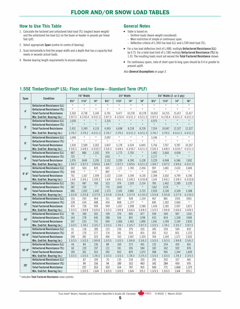
FLOOR AND/OR SNOW LOAD TABLES
General Notes■ Table is based on: – Uniform loads (beam weight considered). – More restrictive of simple or continuous span. – Deflection criteria of L/360 live load (LL) and L/240 total load (TL).
■ For a live load deflection limit of L/480, multiply Unfactored Resistance (LL) by 0.75. For a total load limit of L /180 multiply Unfactored Resistance (TL) by 1.33. The resulting loads must not exceed the Total Factored Resistance shown.
■ For continuous spans, ratio of short span to long span should be 0.4 or greater to prevent uplift.
Also General Assumptions on page 3.
How to Use This Table1. Calculate the factored and unfactored total load (TL) (neglect beam weight)
and the unfactored live load (LL) on the beam or header in pounds per linear foot (plf).
2. Select appropriate Span (centre-to-centre of bearing).
3. Scan horizontally to find the proper width and a depth that has a capacity that meets or exceeds actual loads.
4. Review bearing length requirements to ensure adequacy.
* Indicates Total Factored Resistance value controls.
1.55E TimberStrand® LSL: Floor and /or Snow—Standard Term (PLF)
6Trus Joist® Beam, Header, and Column Specifier’s Guide (W. Canada) TJ-9505 | March 2020
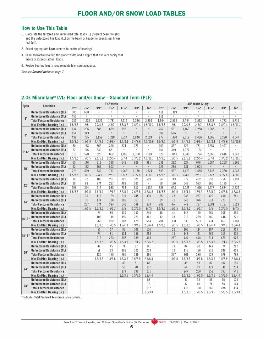
FLOOR AND/OR SNOW LOAD TABLES
Span Condition1¾" Width 3½" Width (2-ply)
5½" 7¼" 9¼" 9½" 11¼" 117⁄8" 14" 5½" 7¼" 9¼" 9½" 11¼" 117⁄8" 14"
6'
Unfactored Resistance (LL)Unfactored Resistance (TL)Total Factored ResistanceMin. End/Int. Bearing (in.)
305 660 * * * * * 611 1,319 * * * * *455 * * * * * * 911 * * * * * *782 1,278 1,722 1,781 2,219 2,386 2,859 1,564 2,556 3,444 3,562 4,438 4,773 5,713
1.5/3.5 2/5 2.7/6.8 2.8/7 3.5/8.7 3.8/9.4 4.5/11.3 1.5/3.5 2/5 2.7/6.8 2.8/7 3.5/8.7 3.8/9.4 4.5/11.3
8'
Unfactored Resistance (LL)Unfactored Resistance (TL)Total Factored ResistanceMin. End/Int. Bearing (in.)
134 296 585 629 992 * * 267 591 1,169 1,258 1,985 * *154 343 * * * * * 308 686 * * * * *438 735 1,159 1,218 1,534 1,640 2,024 877 1,470 2,318 2,436 3,068 3,280 4,047
1.5/3.5 1.5/3.9 2.4/6.1 2.6/6.4 3.2/8.1 3.4/8.6 4.3/10.6 1.5/3.5 1.5/3.9 2.4/6.1 2.6/6.4 3.2/8.1 3.4/8.6 4.3/10.6
9'-6"
Unfactored Resistance (LL)Unfactored Resistance (TL)Total Factored ResistanceMin. End/Int. Bearing (in.)
80 178 362 390 624 723 * 160 357 724 781 1248 1,447 *77 175 539 581 * * * 154 349 1,077 1,162 * * *310 520 820 862 1,182 1,308 1,624 620 1,040 1,640 1,724 2,365 2,616 3,248
1.5/3.5 1.5/3.5 2.1/5.1 2.2/5.4 3/7.4 3.3/8.2 4.1/10.1 1.5/3.5 1.5/3.5 2.1/5.1 2.2/5.4 3/7.4 3.3/8.2 4.1/10.1
10'
Unfactored Resistance (LL)Unfactored Resistance (TL)Total Factored ResistanceMin. End/Int. Bearing (in.)
65 146 313 338 542 629 981 131 292 627 676 1,084 1,258 1,96162 142 465 502 * * * 125 285 931 1,004 * * *279 469 739 777 1,066 1,180 1,524 559 937 1,479 1,555 2,133 2,360 3,047
1.5/3.5 1.5/3.5 2/4.9 2/5.1 2.8/7 3.1/7.8 4/10 1.5/3.5 1.5/3.5 2/4.9 2/5.1 2.8/7 3.1/7.8 4/10
12'
Unfactored Resistance (LL)Unfactored Resistance (TL)Total Factored ResistanceMin. End/Int. Bearing (in.)
32 72 186 201 326 379 599 64 143 372 402 651 758 1,19829 68 274 297 483 563 * 58 136 549 593 965 1,125 *193 324 512 538 738 817 1,112 386 648 1,023 1,076 1,477 1,634 2,224
1.5/3.5 1.5/3.5 1.6/4.1 1.7/4.3 2.3/5.9 2.6/6.5 3.5/8.8 1.5/3.5 1.5/3.5 1.6/4.1 1.7/4.3 2.3/5.9 2.6/6.5 3.5/8.8
14'
Unfactored Resistance (LL)Unfactored Resistance (TL)Total Factored ResistanceMin. End/Int. Bearing (in.)
39 119 129 210 245 390 35 78 238 257 420 490 78135 174 188 309 361 * 29 71 348 376 618 723 *237 374 394 541 598 814 282 474 749 787 1,081 1,197 1,629
1.5/3.5 1.5/3.5 1.5/3.7 2/5 2.2/5.5 3/7.5 1.5/3.5 1.5/3.5 1.5/3.5 1.5/3.7 2/5 2.2/5.5 3/7.5
16'-6"
Unfactored Resistance (LL)Unfactored Resistance (TL)Total Factored ResistanceMin. End/Int. Bearing (in.)
74 80 130 153 245 18 41 147 159 261 305 490106 115 190 223 361 12 33 212 229 380 446 721268 282 387 429 584 201 338 536 563 774 857 1,168
1.5/3.5 1.5/3.5 1.7/4.3 1.9/4.7 2.6/6.4 1.5/3.5 1.5/3.5 1.5/3.5 1.5/3.5 1.7/4.3 1.9/4.7 2.6/6.4
18'-6"
Unfactored Resistance (LL)Unfactored Resistance (TL)Total Factored ResistanceMin. End/Int. Bearing (in.)
53 57 93 109 176 26 105 114 187 219 35374 81 134 158 258 19 148 161 269 316 515
212 223 307 339 463 267 424 446 613 679 9251.5/3.5 1.5/3.5 1.5/3.8 1.7/4.2 2.3/5.7 1.5/3.5 1.5/3.5 1.5/3.5 1.5/3.8 1.7/4.2 2.3/5.7
20'
Unfactored Resistance (LL)Unfactored Resistance (TL)Total Factored ResistanceMin. End/Int. Bearing (in.)
42 45 74 87 141 19 84 90 149 174 28258 63 106 125 204 12 116 126 212 249 408180 190 261 289 395 227 361 380 522 579 789
1.5/3.5 1.5/3.5 1.5/3.5 1.6/3.9 2.1/5.3 1.5/3.5 1.5/3.5 1.5/3.5 1.5/3.5 1.6/3.9 2.1/5.3
24'
Unfactored Resistance (LL)Unfactored Resistance (TL)Total Factored ResistanceMin. End/Int. Bearing (in.)
43 51 83 49 53 87 102 16659 70 117 64 69 119 141 234179 199 271 247 260 358 397 543
1.5/3.5 1.5/3.5 1.8/4.4 1.5/3.5 1.5/3.5 1.5/3.5 1.5/3.5 1.8/4.4
28'
Unfactored Resistance (LL)Unfactored Resistance (TL)Total Factored ResistanceMin. End/Int. Bearing (in.)
53 31 33 55 65 10572 37 40 71 85 144197 178 188 260 288 394
1.5/3.8 1.5/3.5 1.5/3.5 1.5/3.5 1.5/3.5 1.5/3.8
2.0E Microllam® LVL: Floor and /or Snow—Standard Term (PLF)
How to Use This Table1. Calculate the factored and unfactored total load (TL) (neglect beam weight)
and the unfactored live load (LL) on the beam or header in pounds per linear foot (plf).
2. Select appropriate Span (centre-to-centre of bearing).
3. Scan horizontally to find the proper width and a depth that has a capacity that meets or exceeds actual loads.
4. Review bearing length requirements to ensure adequacy.
Also see General Notes on page 7.
* Indicates Total Factored Resistance value controls.

7Trus Joist® Beam, Header, and Column Specifier’s Guide (W. Canada) TJ-9505 | March 2020
FLOOR AND/OR SNOW LOAD TABLES
General Notes■ Table is based on: – Uniform loads (beam weight considered). – More restrictive of simple or continuous span. – Deflection criteria of L/360 live load (LL) and L/240 total load (TL).
■ For a live load deflection limit of L/480, multiply Unfactored Resistance (LL) by 0.75. For a total load limit of L r/180 multiply Unfactored Resistance (TL) by 1.33. The resulting loads must not exceed the Total Factored Resistance shown.
■ For continuous spans, ratio of short span to long span should be 0.4 or greater to prevent uplift.
Also see How to Use This Table on page 6 and General Assumptions on page 3.
2.0E Microllam® LVL: Floor and /or Snow—Standard Term (PLF) continued
Span Condition3½" Width (2-ply) 5¼" Width (3-ply)
16" 18" 20" 5½" 7¼" 9¼" 9½" 11¼" 117⁄8" 14" 16" 18" 20"
6'
Unfactored Resistance (LL)Unfactored Resistance (TL)Total Factored ResistanceMin. End/Int. Bearing (in.)
* * * 916 1,979 * * * * * * * ** * * 1,366 * * * * * * * * *
5,713 5,713 5,713 2,346 3,834 5,166 5,343 6,656 7,159 8,569 8,569 8,569 8,5694.5/11.3 4.5/11.3 4.5/11.3 1.5/3.5 2/5 2.7/6.8 2.8/7 3.5/8.7 3.8/9.4 4.5/11.3 4.5/11.3 4.5/11.3 4.5/11.3
8'
Unfactored Resistance (LL)Unfactored Resistance (TL)Total Factored ResistanceMin. End/Int. Bearing (in.)
* * * 401 887 1,754 1,887 2,977 * * * * ** * * 462 1,028 * * * * * * * *
4,279 4,279 4,279 1,315 2,205 3,476 3,654 4,602 4,921 6,071 6,419 6,419 6,4194.5/11.3 4.5/11.3 4.5/11.3 1.5/3.5 1.5/3.9 2.4/6.1 2.6/6.4 3.2/8.1 3.4/8.6 4.3/10.6 4.5/11.3 4.5/11.3 4.5/11.3
9'-6"
Unfactored Resistance (LL)Unfactored Resistance (TL)Total Factored ResistanceMin. End/Int. Bearing (in.)
* * * 240 535 1,087 1,171 1,873 2,170 * * * ** * * 231 524 1,616 1,742 * * * * * *
3,600 3,600 3,600 930 1,560 2,460 2,586 3,547 3,924 4,872 5,401 5,401 5,4014.5/11.3 4.5/11.3 4.5/11.3 1.5/3.5 1.5/3.5 2.1/5.1 2.2/5.4 3/7.4 3.3/8.2 4.1/10.1 4.5/11.3 4.5/11.3 4.5/11.3
10'
Unfactored Resistance (LL)Unfactored Resistance (TL)Total Factored ResistanceMin. End/Int. Bearing (in.)
* * * 196 439 940 1,014 1,626 1,887 2,942 * * ** * * 187 427 1,396 1,506 * * * * * *
3,419 3,419 3,419 838 1,406 2,218 2,332 3,199 3,540 4,571 5,129 5,129 5,1294.5/11.3 4.5/11.3 4.5/11.3 1.5/3.5 1.5/3.5 2/4.9 2/5.1 2.8/7 3.1/7.8 4/10 4.5/11.3 4.5/11.3 4.5/11.3
12'
Unfactored Resistance (LL)Unfactored Resistance (TL)Total Factored ResistanceMin. End/Int. Bearing (in.)
* * * 95 215 558 603 977 1,137 1,798 2,583 * ** * * 87 204 823 890 1,448 1,688 * * * *
2,846 2,846 2,846 579 972 1,535 1,614 2,215 2,451 3,336 4,269 4,269 4,2694.5/11.3 4.5/11.3 4.5/11.3 1.5/3.5 1.5/3.5 1.6/4.1 1.7/4.3 2.3/5.9 2.6/6.5 3.5/8.8 4.5/11.3 4.5/11.3 4.5/11.3
14'
Unfactored Resistance (LL)Unfactored Resistance (TL)Total Factored ResistanceMin. End/Int. Bearing (in.)
1,132 1,561 * 52 117 357 386 629 735 1,171 1,698 2,342 ** * * 43 106 522 565 927 1,084 * * * *
2,092 2,437 2,437 422 711 1,123 1,181 1,622 1,795 2,443 3,138 3,655 3,6553.9/9.7 4.5/11.3 4.5/11.3 1.5/3.5 1.5/3.5 1.5/3.5 1.5/3.7 2/5 2.2/5.5 3/7.5 3.9/9.7 4.5/11.3 4.5/11.3
16'-6"
Unfactored Resistance (LL)Unfactored Resistance (TL)Total Factored ResistanceMin. End/Int. Bearing (in.)
716 996 1,331 27 61 221 239 391 458 735 1,074 1,493 1,996* * * 19 50 317 344 570 669 1,082 * * *
1,500 1,871 2,064 301 508 804 845 1,162 1,286 1,752 2,250 2,807 3,0963.3/8.2 4.1/10.2 4.5/11.3 1.5/3.5 1.5/3.5 1.5/3.5 1.5/3.5 1.7/4.3 1.9/4.7 2.6/6.4 3.3/8.2 4.1/10.2 4.5/11.3
18'-6"
Unfactored Resistance (LL)Unfactored Resistance (TL)Total Factored ResistanceMin. End/Int. Bearing (in.)
518 723 971 17 39 158 171 280 328 529 777 1,084 1,456760 * * 9 28 223 242 403 474 773 1,140 * *
1,189 1,484 1,808 237 401 636 668 920 1,018 1,388 1,784 2,226 2,7122.9/7.3 3.6/9.1 4.4/11.1 1.5/3.5 1.5/3.5 1.5/3.5 1.5/3.5 1.5/3.8 1.7/4.2 2.3/5.7 2.9/7.3 3.6/9.1 4.4/11.1
20'
Unfactored Resistance (LL)Unfactored Resistance (TL)Total Factored ResistanceMin. End/Int. Bearing (in.)
414 580 781 13 29 125 136 223 262 423 621 870 1,171605 851 * 4 17 174 189 318 374 612 907 1,277 *
1,015 1,266 1,543 202 341 541 569 784 868 1,184 1,522 1,899 2,3152.7/6.8 3.4/8.4 4.1/10.3 1.5/3.5 1.5/3.5 1.5/3.5 1.5/3.5 1.5/3.5 1.6/3.9 2.1/5.3 2.7/6.8 3.4/8.4 4.1/10.3
24'
Unfactored Resistance (LL)Unfactored Resistance (TL)Total Factored ResistanceMin. End/Int. Bearing (in.)
244 344 466 14 73 79 130 153 248 367 516 698350 498 678 3 95 104 178 211 351 526 746 1,017698 872 1,064 233 371 390 538 596 814 1,048 1,308 1,596
2.3/5.6 2.8/7.0 3.4/8.6 1.5/3.5 1.5/3.5 1.5/3.5 1.5/3.5 1.5/3.5 1.8/4.4 2.3/5.6 2.8/7.0 3.4/8.6
28'
Unfactored Resistance (LL)Unfactored Resistance (TL)Total Factored ResistanceMin. End/Int. Bearing (in.)
156 220 299 46 50 83 97 158 234 330 448217 311 428 55 60 107 127 215 326 467 641508 635 775 268 282 389 432 591 761 952 1,162
1.9/4.8 2.4/6.0 2.9/7.3 1.5/3.5 1.5/3.5 1.5/3.5 1.5/3.5 1.5/3.8 1.9/4.8 2.4/6.0 2.9/7.3
* Indicates Total Factored Resistance value controls.
8Trus Joist® Beam, Header, and Column Specifier’s Guide (W. Canada) TJ-9505 | March 2020
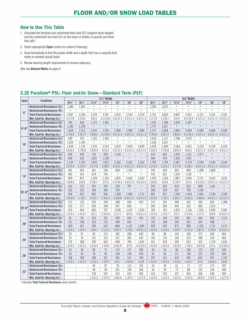
FLOOR AND/OR SNOW LOAD TABLES
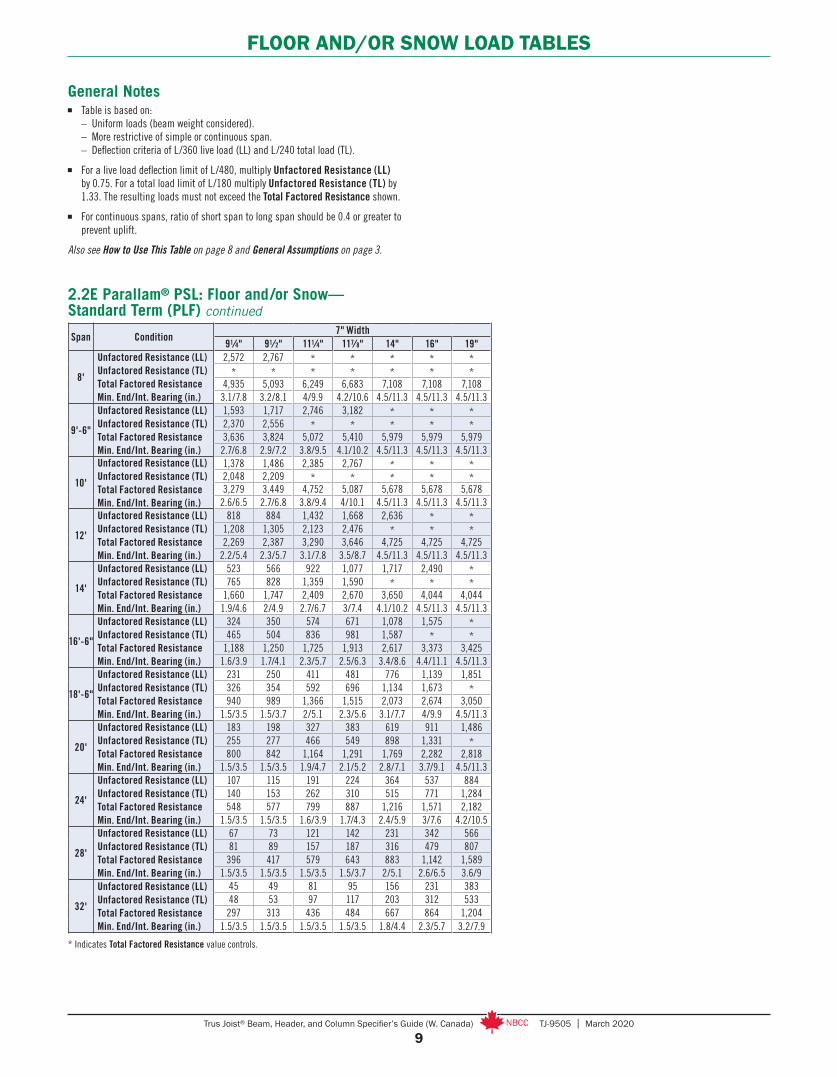
2.2E Parallam® PSL: Floor and /or Snow—Standard Term (PLF)
How to Use This Table1. Calculate the factored and unfactored total load (TL) (neglect beam weight)
and the unfactored live load (LL) on the beam or header in pounds per linear foot (plf).
2. Select appropriate Span (centre-to-centre of bearing).
3. Scan horizontally to find the proper width and a depth that has a capacity that meets or exceeds actual loads.
4. Review bearing length requirements to ensure adequacy.
Also see General Notes on page 9.
* Indicates Total Factored Resistance value controls.
Span Condition31⁄2" Width 51/4" Width
91⁄4" 91⁄2" 111⁄4" 117⁄8" 14" 16" 19" 91⁄4" 91⁄2" 111⁄4" 117⁄8" 14" 16" 19"
8'
Unfactored Resistance (LL)Unfactored Resistance (TL)Total Factored ResistanceMin. End/Int. Bearing (in.)
1,286 1,383 * * * * * 1,929 2,075 * * * * ** * * * * * * * * * * * * *
2,467 2,546 3,124 3,341 3,554 3,554 3,554 3,701 3,820 4,687 5,012 5,331 5,331 5,3313.1/7.8 3.2/8.1 4/9.9 4.2/10.6 4.5/11.3 4.5/11.3 4.5/11.3 3.1/7.8 3.2/8.1 4/9.9 4.2/10.6 4.5/11.3 4.5/11.3 4.5/11.3
9'-6"
Unfactored Resistance (LL)Unfactored Resistance (TL)Total Factored ResistanceMin. End/Int. Bearing (in.)
796 858 1,373 1,591 * * * 1,195 1,288 2,059 2,387 * * *1,185 1,278 * * * * * 1,777 1,917 * * * * *1,818 1,912 2,536 2,705 2,989 2,989 2,989 2,727 2,868 3,804 4,058 4,484 4,484 4,484
2.7/6.8 2.9/7.2 3.8/9.5 4.1/10.2 4.5/11.3 4.5/11.3 4.5/11.3 2.7/6.8 2.9/7.2 3.8/9.5 4.1/10.2 4.5/11.3 4.5/11.3 4.5/11.3
10'
Unfactored Resistance (LL)Unfactored Resistance (TL)Total Factored ResistanceMin. End/Int. Bearing (in.)
689 743 1,192 1,383 * * * 1,034 1,115 1,788 2,075 * * *1,024 1,104 * * * * * 1,536 1,657 * * * * *1,639 1,724 2,376 2,543 2,839 2,839 2,839 2,459 2,586 3,564 3,815 4,259 4,259 4,259
2.6/6.5 2.7/6.8 3.8/9.4 4/10.1 4.5/11.3 4.5/11.3 4.5/11.3 2.6/6.5 2.7/6.8 3.8/9.4 4/10.1 4.5/11.3 4.5/11.3 4.5/11.3
12'
Unfactored Resistance (LL)Unfactored Resistance (TL)Total Factored ResistanceMin. End/Int. Bearing (in.)
409 442 716 834 1,318 * * 614 663 1,074 1,251 1,977 * *604 652 1,061 1,238 * * * 906 979 1,592 1,857 * * *
1,134 1,193 1,645 1,823 2,362 2,362 2,362 1,702 1,790 2,467 2,734 3,544 3,544 3,5442.2/5.4 2.3/5.7 3.1/7.8 3.5/8.7 4.5/11.3 4.5/11.3 4.5/11.3 2.2/5.4 2.3/5.7 3.1/7.8 3.5/8.7 4.5/11.3 4.5/11.3 4.5/11.3
14'
Unfactored Resistance (LL)Unfactored Resistance (TL)Total Factored ResistanceMin. End/Int. Bearing (in.)
261 283 461 538 858 1,245 * 392 424 692 808 1,288 1,868 *382 414 679 795 * * * 574 621 1,019 1,192 * * *830 873 1,204 1,335 1,825 2,022 2,022 1,245 1,310 1,807 2,002 2,737 3,033 3,033
1.9/4.6 2/4.9 2.7/6.7 3/7.4 4.1/10.2 4.5/11.3 4.5/11.3 1.9/4.6 2/4.9 2.7/6.7 3/7.4 4.1/10.2 4.5/11.3 4.5/11.3
16'-6"
Unfactored Resistance (LL)Unfactored Resistance (TL)Total Factored ResistanceMin. End/Int. Bearing (in.)
162 175 287 335 539 787 * 243 262 430 503 808 1,181 *232 252 418 490 793 * * 349 378 627 736 1,190 * *594 625 862 956 1,308 1,686 1,712 891 937 1,294 1,434 1,962 2,530 2,569
1.6/3.9 1.7/4.1 2.3/5.7 2.5/6.3 3.4/8.6 4.4/11.1 4.5/11.3 1.6/3.9 1.7/4.1 2.3/5.7 2.5/6.3 3.4/8.6 4.4/11.1 4.5/11.3
18'-6"
Unfactored Resistance (LL)Unfactored Resistance (TL)Total Factored ResistanceMin. End/Int. Bearing (in.)
115 125 205 240 388 569 925 173 187 308 361 582 854 1,388163 177 296 348 567 836 * 245 266 444 522 850 1,255 *470 494 683 757 1,036 1,337 1,525 705 742 1,025 1,136 1,555 2,005 2,287
1.5/3.5 1.5/3.7 2/5.1 2.3/5.6 3.1/7.7 4/9.9 4.5/11.3 1.5/3.5 1.5/3.7 2/5.1 2.3/5.6 3.1/7.7 4/9.9 4.5/11.3
20'
Unfactored Resistance (LL)Unfactored Resistance (TL)Total Factored ResistanceMin. End/Int. Bearing (in.)
91 99 163 191 309 455 743 137 149 245 287 464 683 1,115127 138 233 274 449 665 * 191 208 349 412 674 998 *400 421 582 645 884 1,141 1,409 600 632 873 968 1,326 1,711 2,113
1.5/3.5 1.5/3.5 1.9/4.7 2.1/5.2 2.8/7.1 3.7/9.1 4.5/11.3 1.5/3.5 1.5/3.5 1.9/4.7 2.1/5.2 2.8/7.1 3.7/9.1 4.5/11.3
24'
Unfactored Resistance (LL)Unfactored Resistance (TL)Total Factored ResistanceMin. End/Int. Bearing (in.)
53 57 95 112 182 268 442 80 86 143 168 273 403 66370 76 131 155 257 385 642 105 114 196 233 386 578 963274 288 399 443 608 785 1,091 411 433 599 665 912 1,178 1,636
1.5/3.5 1.5/3.5 1.6/3.9 1.7/4.3 2.4/5.9 3/7.6 4.2/10.5 1.5/3.5 1.5/3.5 1.6/3.9 1.7/4.3 2.4/5.9 3/7.6 4.2/10.5
28'
Unfactored Resistance (LL)Unfactored Resistance (TL)Total Factored ResistanceMin. End/Int. Bearing (in.)
33 36 60 71 115 171 283 50 55 90 106 173 257 42440 44 78 93 158 239 403 61 66 117 140 237 359 605198 208 289 321 441 571 794 297 312 434 482 662 857 1,192
1.5/3.5 1.5/3.5 1.5/3.5 1.5/3.7 2/5.1 2.6/6.5 3.6/9 1.5/3.5 1.5/3.5 1.5/3.5 1.5/3.7 2/5.1 2.6/6.5 3.6/9
32'
Unfactored Resistance (LL)Unfactored Resistance (TL)Total Factored ResistanceMin. End/Int. Bearing (in.)
40 47 78 115 191 34 36 61 71 117 173 28748 58 101 156 266 36 39 73 88 152 234 400218 242 333 432 602 223 235 327 363 500 648 903
1.5/3.5 1.5/3.5 1.8/4.4 2.3/5.7 3.2/7.9 1.5/3.5 1.5/3.5 1.5/3.5 1.5/3.5 1.8/4.4 2.3/5.7 3.2/7.9
9Trus Joist® Beam, Header, and Column Specifier’s Guide (W. Canada) TJ-9505 | March 2020
FLOOR AND/OR SNOW LOAD TABLES
General Notes■ Table is based on: – Uniform loads (beam weight considered). – More restrictive of simple or continuous span. – Deflection criteria of L/360 live load (LL) and L/240 total load (TL).
■ For a live load deflection limit of L/480, multiply Unfactored Resistance (LL) by 0.75. For a total load limit of L/180 multiply Unfactored Resistance (TL) by 1.33. The resulting loads must not exceed the Total Factored Resistance shown.
■ For continuous spans, ratio of short span to long span should be 0.4 or greater to prevent uplift.
Also see How to Use This Table on page 8 and General Assumptions on page 3.
2.2E Parallam® PSL: Floor and /or Snow— Standard Term (PLF) continued
* Indicates Total Factored Resistance value controls.
Span Condition7" Width
91⁄4" 91⁄2" 111⁄4" 117⁄8" 14" 16" 19"
8'
Unfactored Resistance (LL)Unfactored Resistance (TL)Total Factored ResistanceMin. End/Int. Bearing (in.)
2,572 2,767 * * * * ** * * * * * *
4,935 5,093 6,249 6,683 7,108 7,108 7,1083.1/7.8 3.2/8.1 4/9.9 4.2/10.6 4.5/11.3 4.5/11.3 4.5/11.3
9'-6"
Unfactored Resistance (LL)Unfactored Resistance (TL)Total Factored ResistanceMin. End/Int. Bearing (in.)
1,593 1,717 2,746 3,182 * * *2,370 2,556 * * * * *3,636 3,824 5,072 5,410 5,979 5,979 5,979
2.7/6.8 2.9/7.2 3.8/9.5 4.1/10.2 4.5/11.3 4.5/11.3 4.5/11.3
10'
Unfactored Resistance (LL)Unfactored Resistance (TL)Total Factored ResistanceMin. End/Int. Bearing (in.)
1,378 1,486 2,385 2,767 * * *2,048 2,209 * * * * *3,279 3,449 4,752 5,087 5,678 5,678 5,678
2.6/6.5 2.7/6.8 3.8/9.4 4/10.1 4.5/11.3 4.5/11.3 4.5/11.3
12'
Unfactored Resistance (LL)Unfactored Resistance (TL)Total Factored ResistanceMin. End/Int. Bearing (in.)
818 884 1,432 1,668 2,636 * *1,208 1,305 2,123 2,476 * * *2,269 2,387 3,290 3,646 4,725 4,725 4,725
2.2/5.4 2.3/5.7 3.1/7.8 3.5/8.7 4.5/11.3 4.5/11.3 4.5/11.3
14'
Unfactored Resistance (LL)Unfactored Resistance (TL)Total Factored ResistanceMin. End/Int. Bearing (in.)
523 566 922 1,077 1,717 2,490 *765 828 1,359 1,590 * * *
1,660 1,747 2,409 2,670 3,650 4,044 4,0441.9/4.6 2/4.9 2.7/6.7 3/7.4 4.1/10.2 4.5/11.3 4.5/11.3
16'-6"
Unfactored Resistance (LL)Unfactored Resistance (TL)Total Factored ResistanceMin. End/Int. Bearing (in.)
324 350 574 671 1,078 1,575 *465 504 836 981 1,587 * *
1,188 1,250 1,725 1,913 2,617 3,373 3,4251.6/3.9 1.7/4.1 2.3/5.7 2.5/6.3 3.4/8.6 4.4/11.1 4.5/11.3
18'-6"
Unfactored Resistance (LL)Unfactored Resistance (TL)Total Factored ResistanceMin. End/Int. Bearing (in.)
231 250 411 481 776 1,139 1,851326 354 592 696 1,134 1,673 *940 989 1,366 1,515 2,073 2,674 3,050
1.5/3.5 1.5/3.7 2/5.1 2.3/5.6 3.1/7.7 4/9.9 4.5/11.3
20'
Unfactored Resistance (LL)Unfactored Resistance (TL)Total Factored ResistanceMin. End/Int. Bearing (in.)
183 198 327 383 619 911 1,486255 277 466 549 898 1,331 *800 842 1,164 1,291 1,769 2,282 2,818
1.5/3.5 1.5/3.5 1.9/4.7 2.1/5.2 2.8/7.1 3.7/9.1 4.5/11.3
24'
Unfactored Resistance (LL)Unfactored Resistance (TL)Total Factored ResistanceMin. End/Int. Bearing (in.)
107 115 191 224 364 537 884140 153 262 310 515 771 1,284548 577 799 887 1,216 1,571 2,182
1.5/3.5 1.5/3.5 1.6/3.9 1.7/4.3 2.4/5.9 3/7.6 4.2/10.5
28'
Unfactored Resistance (LL)Unfactored Resistance (TL)Total Factored ResistanceMin. End/Int. Bearing (in.)
67 73 121 142 231 342 56681 89 157 187 316 479 807
396 417 579 643 883 1,142 1,5891.5/3.5 1.5/3.5 1.5/3.5 1.5/3.7 2/5.1 2.6/6.5 3.6/9
32'
Unfactored Resistance (LL)Unfactored Resistance (TL)Total Factored ResistanceMin. End/Int. Bearing (in.)
45 49 81 95 156 231 38348 53 97 117 203 312 533297 313 436 484 667 864 1,204
1.5/3.5 1.5/3.5 1.5/3.5 1.5/3.5 1.8/4.4 2.3/5.7 3.2/7.9
10Trus Joist® Beam, Header, and Column Specifier’s Guide (W. Canada) TJ-9505 | March 2020
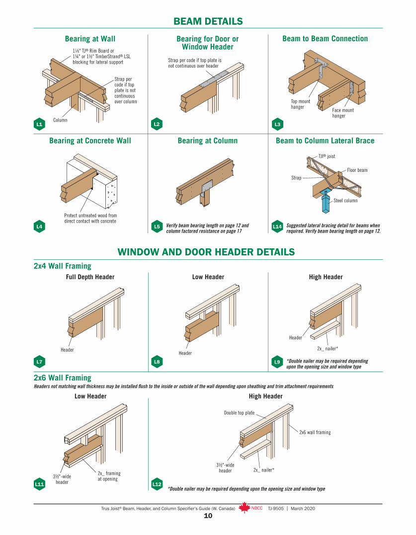
BEAM DETAILS
TJI® joist
Floor beam
Steel column
Strap
2x_ framing at opening
2x_ nailer*
*Double nailer may be required depending upon the opening size and window type
L7 L8 L9
L11
Low Header High Header
Low Header
Header
Full Depth Header
Header
Header
Bearing at Wall
L1
Strap per code if top plate is not continuous over header
L2
Bearing for Door or Window Header
Face mount hanger
Top mount hanger
L3
Beam to Beam Connection
Verify beam bearing length on page 12 and column factored resistance on page 17
Protect untreated wood from direct contact with concrete
Suggested lateral bracing detail for beams when required. Verify beam bearing length on page 12.
L4
Bearing at Concrete Wall Bearing at Column
L5 L14
Beam to Column Lateral Brace
WINDOW AND DOOR HEADER DETAILS2x4 Wall Framing
2x6 Wall FramingHeaders not matching wall thickness may be installed flush to the inside or outside of the wall depending upon sheathing and trim attachment requirements
Double top plate
2x_ nailer*
2x6 wall framing
L12
High Header
*Double nailer may be required depending upon the opening size and window type
Column
Strap per code if top plate is not continuous over column
3½"-wide header
3½"-wide header
11⁄8" TJ® Rim Board or 1¼" or 1½" TimberStrand® LSL blocking for lateral support

11Trus Joist® Beam, Header, and Column Specifier’s Guide (W. Canada) TJ-9505 | March 2020
WINDOW AND DOOR HEADER DETAILS
L15
L16
NAILING ON NARROW FACE
Nail SizeClosest On-Centre Spacing Per Row
TimberStrand® LSL Microllam® LVL Parallam® PSL8d (0.131" x 2½") or
10d (0.128" x 3") 3" 4" 4"
10d (0.148" x 3") or 12d (0.148" x 3¼") 3" 5" 4"
16d (0.162" x 3½") 6"(1) 8"(2) 6"
Nails Installed on the Narrow Face
(1) Can be reduced to 3½" on-centre if nail penetration into the narrow edge is no more than 1¼" (to minimize splitting).(2) Can be reduced to 5" on-centre if nail penetration into the narrow edge is no more than 1¼" (to minimize splitting).■ To minimize splitting, member edge distance and spacing between rows shall be 2.5 x nail diameter or 3⁄8", whichever is greater.
Where multiple rows are used, fasteners in adjacent rows must be staggered and the rows must be equally spaced from the centreline of the narrow face axis.
See pages 16–18 for connecting multiple plies
Continuous king stud
Sheathing strength axis
One 8d (0.113" x 2½") nail each side of joist or blocking. Blocking is required if joist framing is parallel to beam. Joist spacing must be 24" on-centre or less.
4'-0" maximum height cripple wall. Wall studs at 24" on-centre, maximum.
Fasten 2x_ plate to header below with 10d (0.131" x 3") nails at 8" on-centre, staggered
Nail continuous king studs to the end of the beam using:– Four 10d (0.131" x 3") nails for beams 117⁄8" deep or less– Six 10d (0.131" x 3") nails for beams 16" deep or less
Rated wall sheathing (7⁄16" nominal) continuous from bottom of beam to top of wall. Fasten sheathing with 8d (0.113" x 2½") nails at 6" on-centre at panel edges and 12" on-centre in panel field.
Dropped Header with Acceptable Lateral Bracing
Main structural header. See pages 16–18 for connecting multiple plies.
Fasten 2x_ plate to low header with 10d (0.131" x 3") nails at 8" on-centre, staggered
Low headerNail continuous king studs to the end of the beam using:– Four 10d (0.131" x 3") nails for beams 117⁄8" deep or less– Six 10d (0.131" x 3") nails for beams 18" deep or less– Ten 10d (0.131" x 3") nails for beams greater than 18" deep
One 8d (0.113" x 2½") nail each side of joist or blocking. Blocking is required if joist framing is parallel to beam. Joist spacing must be 24" on-centre or less.
Continuous king stud
Framing above must be sheathed to provide lateral stability to the top of the beam
When framed as shown above, the following dropped headers are considered fully braced under uniform-load, simple-span conditions:
Multiple-ply:– Headers up to four 1¾" plies, 117⁄8" deep or less – Headers up to four 1¾" x 14" plies, with a maximum span of 8'-6"
Single-ply:– 1¾" wide headers, 117⁄8" deep or less – 3½" wide headers, 16" deep or less, with a maximum span of 18'-6"
Dropped Header with Full Lateral Bracing
Fastener spacing not applicable for shear wall applications. See CCMC 12627-R report for grade specific TimberStrand® LSL nailing requirements for shear walls.
12Trus Joist® Beam, Header, and Column Specifier’s Guide (W. Canada) TJ-9505 | March 2020
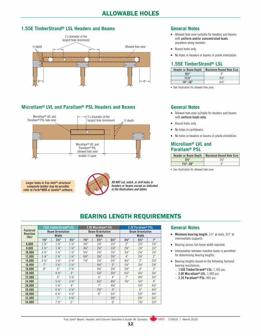
ALLOWABLE HOLES
Microllam® LVL and Parallam® PSL Headers and Beams
BEARING LENGTH REQUIREMENTS
2 x diameter of the largest hole (minimum)
Microllam® LVL and Parallam® PSL
allowed hole zone middle 1⁄3 span
1⁄3 depthMicrollam® LVL and
Parallam® PSL hole zone
Factored Reaction
(lbs)
1.55E TimberStrand® LSL 2.0E Microllam® LVL 2.2E Parallam® PSLBeam Orientation Beam Orientation Beam Orientation
Width Width Width1¾" 3½" 5¼" 1¾" 3½" 5¼" 3½" 5¼" 7"
6,000 2 3/4'' 1 1/2'' 1 1/2'' 3¼" 13/4" 11/2" 2" 11/2" 11/2"8,000 3 1/2'' 1 3/4'' 1 1/2'' 4¼" 2¼" 11/2" 23/4" 13/4" 11/2"10,000 4 1/2'' 2 ¼'' 1 1/2'' 5¼" 23/4" 13/4" 3¼" 2¼" 13/4"12,000 5 ¼'' 2 3/4'' 1 3/4'' 61/2" 3¼" 2¼" 4" 23/4" 2"14,000 6 ¼'' 3 ¼'' 2 ¼'' 71/2" 33/4" 21/2" 41/2" 3" 2¼"16,000 7'' 3 1/2'' 2 1/2'' 4¼" 3" 5¼" 31/2" 23/4"18,000 8'' 4'' 2 3/4'' 43/4" 3¼" 53/4" 4" 3"20,000 4 1/2'' 3'' 5¼" 31/2" 61/2" 4¼" 3¼"22,000 5'' 3 ¼'' 6" 4" 7" 43/4" 31/2"24,000 5 ¼'' 3 1/2'' 61/2" 4¼" 73/4" 5¼" 4"26,000 5 3/4'' 4'' 7" 43/4" 51/2" 4¼"28,000 6 ¼'' 4 ¼'' 71/2" 5" 6" 41/2"30,000 6 3/4'' 4 1/2'' 8" 5¼" 61/2" 43/4"32,000 7'' 4 3/4'' 53/4" 63/4" 5¼"34,000 7 1/2'' 5'' 6" 7¼" 51/2"
General Notes■ Minimum bearing length: 11⁄2" at ends, 31⁄2" at
intermediate supports.
■ Bearing across full beam width required.
■ Interpolation between reaction loads is permitted for determining bearing lengths.
■ Bearing lengths based on the following factored bearing resistances: – 1.55E TimberStrand® LSL: 1,165 psi. – 2.0E Microllam® LVL: 1,090 psi. – 2.2E Parallam® PSL: 905 psi.
1.55E TimberStrand® LSL Headers and Beams2 x diameter of the
largest hole (minimum)
8"
1⁄3 depth Allowed hole zone
8"
General Notes■ Allowed hole zone suitable for headers and beams
with uniform and/or concentrated loads anywhere along member.
■ Round holes only.
■ No holes in headers or beams in plank orientation.
General Notes■ Allowed hole zone suitable for headers and beams
with uniform loads only.
■ Round holes only.
■ No holes in cantilevers.
■ No holes in headers or beams in plank orientation.
Microllam® LVL and Parallam® PSL
Header or Beam Depth Maximum Round Hole Size5½" 13/4"
7¼"–20" 2"■ See illustration for allowed hole zone.
■ See illustration for allowed hole zone.
Header or Beam Depth Maximum Round Hole Size9½" 3"117⁄8" 35⁄8"
14"–16" 45⁄8"
1.55E TimberStrand® LSL
DO NOT cut, notch, or drill holes in headers or beams except as indicated in the illustrations and tables
Larger holes in Trus Joist® structural composite lumber may be possible;
refer to Forte®WEB or Javelin® software.
13Trus Joist® Beam, Header, and Column Specifier’s Guide (W. Canada) TJ-9505 | March 2020
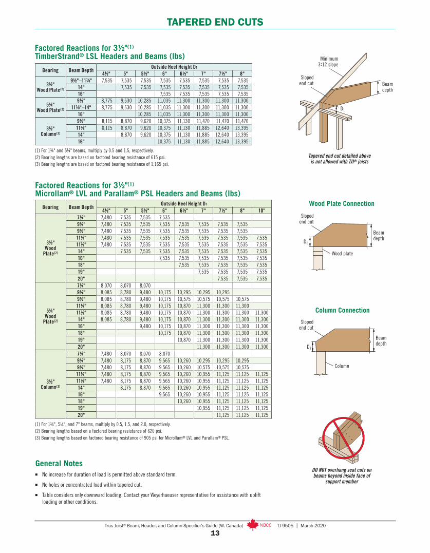
TAPERED END CUTS
(1) For 13⁄4", 51⁄4", and 7" beams, multiply by 0.5, 1.5, and 2.0, respectively.(2) Bearing lengths based on a factored bearing resistance of 620 psi.(3) Bearing lengths based on factored bearing resistance of 905 psi for Microllam® LVL and Parallam® PSL.
Bearing Beam DepthOutside Heel Height D1
4½" 5" 5½" 6" 6½" 7" 7½" 8" 10"
3½" Wood
Plate(2)
7¼" 7,480 7,535 7,535 7,5359¼" 7,480 7,535 7,535 7,535 7,535 7,535 7,535 7,5359½" 7,480 7,535 7,535 7,535 7,535 7,535 7,535 7,53511¼" 7,480 7,535 7,535 7,535 7,535 7,535 7,535 7,535 7,535117⁄8" 7,480 7,535 7,535 7,535 7,535 7,535 7,535 7,535 7,53514" 7,535 7,535 7,535 7,535 7,535 7,535 7,535 7,53516" 7,535 7,535 7,535 7,535 7,535 7,53518" 7,535 7,535 7,535 7,535 7,53519" 7,535 7,535 7,535 7,53520" 7,535 7,535 7,535
5¼" Wood
Plate(2)
7¼" 8,070 8,070 8,0709¼" 8,085 8,780 9,480 10,175 10,295 10,295 10,2959½" 8,085 8,780 9,480 10,175 10,575 10,575 10,575 10,57511¼" 8,085 8,780 9,480 10,175 10,870 11,300 11,300 11,300117⁄8" 8,085 8,780 9,480 10,175 10,870 11,300 11,300 11,300 11,30014" 8,085 8,780 9,480 10,175 10,870 11,300 11,300 11,300 11,30016" 9,480 10,175 10,870 11,300 11,300 11,300 11,30018" 10,175 10,870 11,300 11,300 11,300 11,30019" 10,870 11,300 11,300 11,300 11,30020" 11,300 11,300 11,300 11,300
3½" Column(3)
7¼" 7,480 8,070 8,070 8,0709¼" 7,480 8,175 8,870 9,565 10,260 10,295 10,295 10,2959½" 7,480 8,175 8,870 9,565 10,260 10,575 10,575 10,57511¼" 7,480 8,175 8,870 9,565 10,260 10,955 11,125 11,125 11,125117⁄8" 7,480 8,175 8,870 9,565 10,260 10,955 11,125 11,125 11,12514" 8,175 8,870 9,565 10,260 10,955 11,125 11,125 11,12516" 9,565 10,260 10,955 11,125 11,125 11,12518" 10,260 10,955 11,125 11,125 11,12519" 10,955 11,125 11,125 11,12520" 11,125 11,125 11,125
Factored Reactions for 3½"(1) Microllam® LVL and Parallam® PSL Headers and Beams (lbs)
Factored Reactions for 3½"(1) TimberStrand® LSL Headers and Beams (lbs)
(1) For 1¾" and 5¼" beams, multiply by 0.5 and 1.5, respectively. (2) Bearing lengths are based on factored bearing resistance of 615 psi.(3) Bearing lengths are based on factored bearing resistance of 1,165 psi.
Bearing Beam DepthOutside Heel Height D1
4½" 5" 5½" 6" 6½" 7" 7½" 8"
3½"Wood Plate(2)
9½"–117⁄8" 7,535 7,535 7,535 7,535 7,535 7,535 7,535 7,53514" 7,535 7,535 7,535 7,535 7,535 7,535 7,53516" 7,535 7,535 7,535 7,535 7,535
5¼"Wood Plate(2)
9½" 8,775 9,530 10,285 11,035 11,300 11,300 11,300 11,300117⁄8"–14" 8,775 9,530 10,285 11,035 11,300 11,300 11,300 11,300
16" 10,285 11,035 11,300 11,300 11,300 11,300
3½"Column(3)
9½" 8,115 8,870 9,620 10,375 11,130 11,470 11,470 11,470117⁄8" 8,115 8,870 9,620 10,375 11,130 11,885 12,640 13,39514" 8,870 9,620 10,375 11,130 11,885 12,640 13,39516" 10,375 11,130 11,885 12,640 13,395
DO NOT overhang seat cuts on beams beyond inside face of
support member
General Notes ■ No increase for duration of load is permitted above standard term.
■ No holes or concentrated load within tapered cut.
■ Table considers only downward loading. Contact your Weyerhaeuser representative for assistance with uplift loading or other conditions.
Minimum 3:12 slope
Sloped end cut Beam
depth
D1
Tapered end cut detailed above is not allowed with TJI® joists
Column Connection
Beam depth
Sloped end cut
Column
D1
Sloped end cut
Beam depth
D1
Wood plate
Wood Plate Connection

14Trus Joist® Beam, Header, and Column Specifier’s Guide (W. Canada) TJ-9505 | March 2020
MULTIPLE-MEMBER CONNECTIONS FOR SIDE-LOADED BEAMS
General Notes for Side-Loaded Beam Tables■ Connections are based on Limit States Design per CSA O86.■ Use specific gravity of 0.5 when designing lateral connections.■ Values listed are for standard term loading.■ When fasteners are required on both sides, stagger fasteners on the second
side so they fall halfway between fasteners on the first side.■ Verify adequacy of beam in allowable load tables on pages 5–9.■ 7" wide beams should be side-loaded only when loads are applied to both sides
of the members (to minimize rotation).■ Minimum end distance for bolts and screws is 6".■ Beams wider than 7" require special consideration by the design professional
of record.
Factored Uniform Load—Maximum Factored Uniform Load Applied to Either Outside Member (PLF)
435 PLF 625 PLF
First, check load tables on pages 5–9 to verify that three pieces can carry the total factored load of 1,060 plf with proper live load deflection criteria. Total factored load = (1.25 x dead load) + (1.5 x live load). Maximum factored load applied to either outside member is 625 plf. For an assembly of three 1¾" plies (Assembly B), two rows of 10d (0.128" x 3") nails at 12" on-centre is good for only 430 plf. Therefore, use three rows of 10d (0.128" x 3") nails at 12" on-centre (good for 650 plf).
Alternatives: Two rows of 1⁄2" bolts or 5" TrussLOK® screws at 19.2" on-centre.
Uniform Load Design Example
L17
(1) Nailed connection values may be doubled for 6" on-centre or tripled for 4" on-centre nail spacing.(2) Washers required. Bolt holes to be 9⁄16" maximum.(3) Factored resistance for 24" on-centre bolted or screwed connection values may be doubled for 12" on-centre spacing.(4) When loading the head side of a SDW22 screw, assemblies A, B, D, and F can be increased by 15%.(5) For beams up to 14" deep, maximum.(6) Assembly F is not recommended for TimberStrand® LSL or Parallam® PSL.
Fastener Type LocationNumber of Rows
Fastener On-Centre
Spacing
Fastener Pattern
Assembly A Assembly B Assembly C Assembly D Assembly E Assembly F
3½" wide, 2-ply 5¼" wide, 3-ply 5¼" wide, 2-ply 7" wide, 3-ply 7" wide, 2-ply 7" wide, 4-ply10d (0.128" x 3")
Nail(1) As shown 2(5) 12" 575 430 430 385
3 12" 865 650 650 575
½" A307 Through Bolt(2)(3) – 2
24" 780 585 880 780 1,560 52019.2" 975 730 1,095 975 1,950 65016" 1,170 880 1,315 1,170 2,340 780
Screw Length 3½" 3½" 3½" 3½" 6" 6"
SDS(3) As shown 224" 870 655 655 580 2,040 680
19.2" 1,090 815 815 725 2,550 85016" 1,305 980 980 870 3,060 1,020
USP WS(3) As shown 224" 905 680 680 605 765(6)
19.2" 1,130 850 850 755 960(6)
16" 1,355 1,015 1,015 905 1,150(6)
Screw Length 33⁄8" 5" 33⁄8" 6¾" 6¾" 6¾"
TrussLOK®(3) One side only 2
24" 840 610 630 540 810 54019.2" 1,050 760 790 675 1,015 67516" 1,260 910 945 810 1,215 810
SDW22(3)(4) One side only 2
24" 680 625 585 555 1,140 55519.2" 850 780 730 690 1,425 69016" 1,020 935 880 830 1,710 830
2"
2"
13⁄4" 13⁄4" 13⁄4" 31⁄2" 13⁄4" 31⁄2" 13⁄4"
2"
2"
31⁄2" 13⁄4"
2"
2"

15Trus Joist® Beam, Header, and Column Specifier’s Guide (W. Canada) TJ-9505 | March 2020
MULTIPLE-MEMBER CONNECTIONS FOR SIDE-LOADED BEAMS
Factored Point Load—Maximum Factored Point Load Applied to Either Outside Member (lbs)
(1) Washers required. Bolt holes to be 9⁄16" maximum.(2) When loading the head side of a SDW22 screw, assemblies A, B, D, and F can be increased by 15%.(3) Assembly F is not recommended for TimberStrand® LSL or Parallam® PSL.
L18
First, verify that a 3-ply, 1¾" x 14" beam can support the factored 3,000 lb point load and all other loads applied. The factored 3,000 lb point load is being transferred to the beam with a face mount hanger. For an assembly of three 1¾" plies (Assembly B), six 5"-long TrussLOK® screws are good for 3,645 lbs with a face mount hanger.
Point Load Design Example3,000 lbs
14"
Point Load Connector Spacing
2" minimum
10d (0.128" x 3" nails, typical. Stagger to prevent splitting.
2" spacing, typical
1½" minimum spacing, typical
2" minimum
8"–10"
8-Bolt or Screw Connection Nail Connection
Minimum beam depth is 9½" for ½" diameter bolts
L19 Minimum beam depth is 117⁄8" for ½" diameter bolts
L20 There must be an equal number of nails on each side of the connection
L21
Equal spacing
2" minimum
2" minimum
½" A307 through bolt, or SDS, USP WS, TrussLOK®, or SDW screw, typical
1½" minimum
4- or 6-Bolt or Screw Connection
2" minimum at top and bottom, typical
½ beam depth
1½" minimum
½" A307 through bolt, or SDS, USP WS, TrussLOK®, or SDW screw, typical
Fastener Type Location
Number of Fasteners per Side
Fastener Pattern
Assembly A Assembly B Assembly C Assembly D Assembly E Assembly F
3½" wide, 2-ply 5¼" wide, 3-ply 5¼" wide, 2-ply 7" wide, 3-ply 7" wide, 2-ply 7" wide, 4-ply
10d (0.128" x 3") Nail As shown
6 1,730 1,295 1,29512 3,455 2,590 2,590 2,30518 5,185 3,890 3,890 3,45524 6,910 5,185 5,185 4,610
½" A307 Through Bolt(1) –
4 3,120 2,340 3,510 3,120 6,240 2,0806 4,680 3,510 5,265 4,680 9,360 3,1208 6,240 4,680 7,020 6,240 12,480 4,160
Screw Length 3½" 3½" 3½" 3½" 6" 6"
SDS As shown4 3,480 2,610 2,610 2,320 8,160 2,7206 5,220 3,915 3,915 3,480 12,240 4,0808 6,960 5,220 5,220 4,640 16,320 5,440
USP WS As shown4 3,615 2,710 2,710 2,410 3,065(3)
6 5,425 4,070 4,070 3,615 4,600(3)
8 7,230 5,425 5,425 4,820 6,135(3)
Screw Length 33⁄8" 5" 33⁄8" 6¾" 6¾" 6¾"
TrussLOK® One side only4 3,360 2,430 2,520 2,160 3,240 2,1606 5,040 3,645 3,780 3,240 4,860 3,2408 6,720 4,860 5,040 4,320 6,480 4,320
SDW22(2) One side only4 2,720 2,490 2,340 2,215 4,560 2,2156 4,080 3,735 3,510 3,320 6,840 3,3208 5,440 4,980 4,680 4,425 9,120 4,425
2"
2"
13⁄4" 13⁄4" 13⁄4" 31⁄2" 31⁄2"
2"
2"
31⁄2" 13⁄4"
2"
2"
13⁄4" 13⁄4"
16Trus Joist® Beam, Header, and Column Specifier’s Guide (W. Canada) TJ-9505 | March 2020
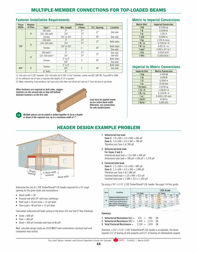
MULTIPLE-MEMBER CONNECTIONS FOR TOP-LOADED BEAMS
Metric to Imperial ConversionsMetric Unit Imperial Conversion
1 kN 0.2248 kip1 N 0.2248 lb1 m 3.281 ft
1 mm 0.0394 in.1 kg 2.205 lb mass
1 N • m 0.7376 lb • ft1 N • m 8.851 lb • in.1 mm4 2.402 x 10⁻⁶ in.4
1 Pa 0.0209 lb/ft2
1 kPa 0.1450 lb/in.2
Imperial Unit Metric Conversion1 kip 4.448 kN1 lb 4.448 N1 ft 0.3048 m1 in. 25.40 mm
1 lb mass 0.4536 kg1 lb • ft 1.356 N • m1 lb • in. 0.1130 N • m
1 in.4 0.4162 x 106 mm4
1 lb/ft2 47.88 Pa1 lb/in.2 6.895 kPa
Imperial to Metric Conversions
L6
Load must be applied evenly across entire beam width. Otherwise, use connections for side-loaded beams
Multiple pieces can be nailed or bolted together to form a header or beam of the required size, up to a maximum width of 7"
PieceWidth
Number of Plies
FastenerType(1) Min. Length # Rows O.C. Spacing Location
1¾"
210d nails 3" 3(2)
12" One side12d–16d nails 3¼" 2(2)
Screws 33∕8" or 3½" 2 24" One side
3
10d nails 3" 3(2)12" Both sides
12d–16d nails 3¼" 2(2)
Screws33∕8" or 3½"
2 24"Both sides
5" One side
4
10d nails(3) 3" 3(2)12" One side
(per ply)12d–16d nails(3) 3¼" 2(2)
Screws5" or 6"
2 24"Both sides
6¾" One side
3½" 2Screws
5" or 6"2 24"
Both sides6¾" One side
½" bolts 8" –
Fastener Installation Requirements
(1) 10d nails are 0.128" diameter; 12d–16d nails are 0.148"–0.162" diameter; screws are SDS, USP WS, TrussLOK® or SDW.(2) An additional row of nails is required with depths of 14" or greater.(3) When connecting 4-ply members, nail each ply to the other and offset nail rows by 2" from the rows in ply below.
When fasteners are required on both sides, stagger fasteners on the second side so they fall halfway between fasteners on the first side.
HEADER DESIGN EXAMPLE PROBLEM
Determine the size of 1.55E TimberStrand® LSL header required for a 10' rough opening for the given loads and assumptions:
■ House width = 36'■ Trussed roof with 24" roof truss overhangs■ Roof Load = 30 psf snow + 15 psf dead■ Floor Load = 40 psf live + 12 psf dead
Calculated unfactored plf loads acting on the beam (20' roof and 9' floor tributary):
■ Snow = 600 plf■ Floor = 360 plf■ Dead = 490 plf (includes wall load at 80 plf)
Next, calculate design loads per 2010 NBCC load combinations (primary load and companion load action).
House width
Rough opening
1⁄2 House width maximum
1. Unfactored live load: Case 2: 1.0 x 360 + 0.5 x 600 = 660 plf Case 3: 1.0 x 600 + 0.5 x 360 = 780 plf Therefore use Case 3 at 780 plf
2. Unfactored total load: For Cases 2 and 3: Unfactored dead load = 1.0 x 490 = 490 plf Unfactored total load = 780 plf + 490 plf = 1,270 plf
3. Factored total load: Case 2: 1.5 x 360 + 0.5 x 600 = 840 plf Case 3: 1.5 x 600 + 0.5 x 360 = 1,080 plf Therefore use Case 3 at 1,080 plf Factored dead load = 1.25 x 490 = 613 plf Factored total load = 1,080 + 613 = 1,693 plf
Try using a 3½" x 117⁄8" 1.55E TimberStrand® LSL header. See page 5 of this guide.
Summary:
1. Unfactored Resistance (LL) = 974 > 780 OK2. Unfactored Resistance (TL) = 1,449 > 1,270 OK3. Total Factored Resistance = 2,106 > 1,693 OK
Therefore, a 3½" x 117⁄8" 1.55E TimberStrand® LSL header is acceptable. The beam requires 2.6" of bearing at end supports and 6.5" of bearing at intermediate support.
Span Condition1.55E Grade
1¾" Width 3½" Width 5¼" Width (2- or 3-ply)9½" 117⁄8" 14" 9½" 117⁄8" 14" 16" 9½" 117⁄8" 14" 16"
10'
Unfactored Resistance (LL) 261 487 760 523 974 1,520 2,154 785 1,462 2,280 3,232Unfactored Resistance (TL) 387 724 * 775 1,449 * * 1,162 2,174 * *Total Factored Resistance 686 1,052 1,442 1,373 2,105 2,885 3,725 2,059 3,158 4,328 5,588Min. End/Int. Bearing (in.) 1.5/3.8 2.3/5.8 3.2/9.7 1.5/3.8 2.3/5.8 3.2/7.9 4.1/10.2 1.5/3.8 2.3/5.8 3.2/7.9 4.1/10.2
12'
Résistance non pondérée (S) 155 293 464 311 587 928 1,334 467 881 1,393 2,001Unfactored Resistance (TL) 228 434 688 456 868 1,377 * 685 1,302 2,066 *Total Factored Resistance 474 728 999 949 1,457 1,998 2,580 1,424 2,185 2,997 3,871Min. End/Int. Bearing (in.) 1.5/3.5 1.9/4.8 2.6/6.6 1.5/3.5 1.9/4.8 2.6/6.6 3.4/8.5 1.5/3.5 1.9/4.8 2.6/6.6 3.4/8.5

17Trus Joist® Beam, Header, and Column Specifier’s Guide (W. Canada) TJ-9505 | March 2020
PARALLAM® PSL COLUMNS
The column values listed are for dry-service conditions ONLY. When wet-service conditions exist,
contact your Weyerhaeuser representative for other product solutions.
Top or Bottom Plate Connection
Column Bearing
Type
Effective Column Length
Column Size
3½" x 3½" 3½" x 5¼" 3½" x 7" 5¼" x 5¼" 5¼" x 7" 7" x 7"
On Column
Base
6' 19,365 29,020 38,435 54,735 72,980 100,0007' 16,245 24,365 32,490 51,350 68,470 100,0008' 13,305 19,955 26,610 47,425 63,230 96,3909' 10,875 16,315 21,750 43,155 57,540 92,07010' 8,900 13,350 17,800 38,740 51,655 87,17012' 6,015 9,025 12,030 29,760 39,680 76,17514' 4,145 6,215 8,275 22,775 30,370 64,23016'
Slenderness ratio exceeds 50
17,480 23,310 52,68518' 13,500 17,995 43,13020' 10,510 14,010 35,34522' 29,04024' 23,945
Axial Factored Resistances (lbs) for 1.8E Parallam® PSL
General Notes■ Tables are based on: – Solid, one-piece column members used in dry-service conditions. – Bracing in both directions at column ends. – CSA O86. – Simple columns with axial loads only. For side loads or other combined bending and axial loads, see the
CSA O86 provisions. – KD = 1.0, where the specified snow or live load is greater than the specified dead load. For other load cases,
use Weyerhaeuser software.
■ Factored resistances have been adjusted to accommodate the worst case of the following eccentric conditions: 1⁄6 of column thickness (first dimension) or 1⁄6 of column width.
■ Beams and columns must remain straight to within 5L2⁄4608 (in.) of true alignment. L is the unrestrained length of the member in feet.
For column specified strengths see page 4.
Column Base
P2
Elevated Column Base
Optionalnon-shrinkgrout
P3
Beam on Column
L1
Wide face of strands
DO NOT install bolts or screws into the narrow face of strands
In order to use the manufacturer’s published capacities when designing column caps, bases, or holdowns for uplift, the bolts or screws must be installed perpendicular to the wide face of strands, as shown above.
Wide face of strands
Beam on Column Cap
P1
Two 16d (0.162" x 3½") nails for every 1¾" of column width, nailed through the plate
into the column
Column
Strap per code if top plate is not continuous over column
11⁄8" TJ® Rim Board or 1¼" or 1½" TimberStrand® LSL blocking for lateral support

18Trus Joist® Beam, Header, and Column Specifier’s Guide (W. Canada) TJ-9505 | March 2020
NOTES
19Trus Joist® Beam, Header, and Column Specifier’s Guide (W. Canada) TJ-9505 | March 2020
NOTES
March 2020 • Reorder TJ-9505 , Weyerhaeuser, Microllam, Parallam, TimberStrand, TJI, and Trus Joist are registered trademarks and Edge Gold is a trademark of Weyerhaeuser NR. © 2020 Weyerhaeuser NR Company. All rights reserved. Printed in the USA.
This document supersedes all previous versions. If this is more than one year old, contact your dealer or Weyerhaeuser rep.
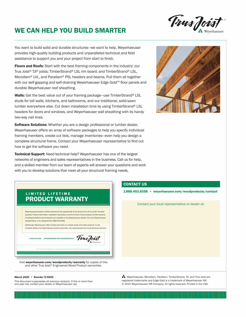
You want to build solid and durable structures—we want to help. Weyerhaeuser provides high-quality building products and unparalleled technical and field assistance to support you and your project from start to finish.
Floors and Roofs: Start with the best framing components in the industry: our Trus Joist® TJI® joists; TimberStrand® LSL rim board; and TimberStrand® LSL, Microllam® LVL, and Parallam® PSL headers and beams. Pull them all together with our self-gapping and self-draining Weyerhaeuser Edge GoldTM floor panels and durable Weyerhaeuser roof sheathing.
Walls: Get the best value out of your framing package—use TimberStrand® LSL studs for tall walls, kitchens, and bathrooms, and our traditional, solid-sawn lumber everywhere else. Cut down installation time by using TimberStrand® LSL headers for doors and windows, and Weyerhaeuser wall sheathing with its handy two-way nail lines.
Software Solutions: Whether you are a design professional or lumber dealer, Weyerhaeuser offers an array of software packages to help you specify individual framing members, create cut lists, manage inventories—even help you design a complete structural frame. Contact your Weyerhaeuser representative to find out how to get the software you need.
Technical Support: Need technical help? Weyerhaeuser has one of the largest networks of engineers and sales representatives in the business. Call us for help, and a skilled member from our team of experts will answer your questions and work with you to develop solutions that meet all your structural framing needs.
WE CAN HELP YOU BUILD SMARTER
CONTACT US
1.888.453.8358 • weyerhaeuser.com/woodproducts/contact
Contact your local representative or dealer at:
Visit weyerhaeuser.com/woodproducts/warranty for copies of this and other Trus Joist® Engineered Wood Product warranties.
Weyerhaeuser provides a limited warranty for the expected life of the structure for all Trus Joist® branded products. Product information, installation instructions, and the full text of each product's limited warranty (including limitations and exclusions) are available on the Weyerhaeuser website, from your Weyerhaeuser representative, or by calling toll free: 888-453-8358.
Additionally, Weyerhaeuser offers limited warranties on a broad variety of its other products. To see complete details of all Weyerhaeuser product warranties, visit weyerhaeuser.com/wood products/warranty.
1.888.453.8358 WEYERHAEUSER.COM/WOODPRODUCTS
PRODUCT WARRANTYL I M I T E D L I F E T I M E
Reorder TJ-1010 December 2016 , Weyerhaeuser, and Trus Joist are registered trademarks of Weyerhaeuser NR. © 2016 Weyerhaeuser NR Company. All rights reserved.