Waters Quality Parts,® Chromatography Columns and Supplies ...
Upload
nguyenkienCategory
view
224download
1
BEAMS, HEADERS, AND COLUMNSFeaturing Trus Joist® TimberStrand® LSL, Microllam® LVL, and Parallam® PSL
• Uniform and Predictable
• Minimal Bowing, Twisting, and Shrinking
• Strong and Straight
• Limited Product Warranty
#TJ-9000 SPECIFIER’S GUIDE
Trus Joist® Beam, Header and Column Specifier's Guide TJ-9000 | October 2017
2
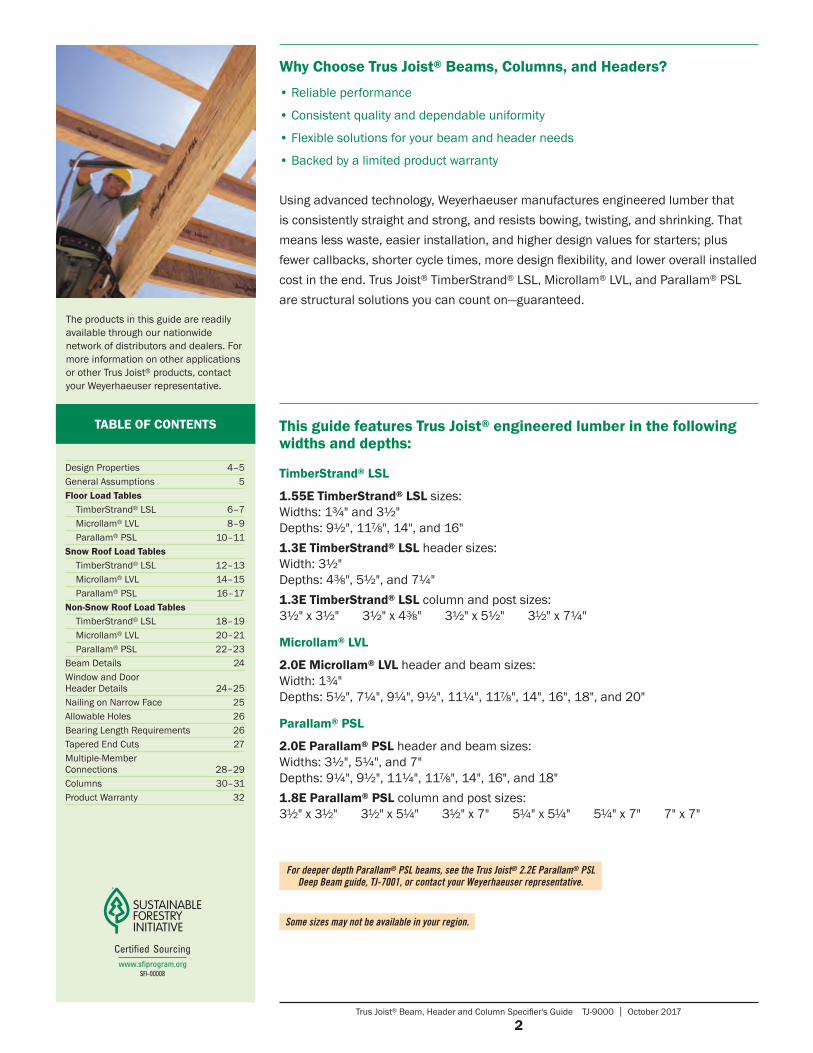
Using advanced technology, Weyerhaeuser manufactures engineered lumber that is consistently straight and strong, and resists bowing, twisting, and shrinking. That means less waste, easier installation, and higher design values for starters; plus fewer callbacks, shorter cycle times, more design flexibility, and lower overall installed cost in the end. Trus Joist® TimberStrand® LSL, Microllam® LVL, and Parallam® PSL are structural solutions you can count on—guaranteed.
Some sizes may not be available in your region.
For deeper depth Parallam® PSL beams, see the Trus Joist® 2.2E Parallam® PSL Deep Beam guide, TJ-7001, or contact your Weyerhaeuser representative.
Why Choose Trus Joist® Beams, Columns, and Headers?
• Reliable performance
• Consistent quality and dependable uniformity
• Flexible solutions for your beam and header needs
• Backed by a limited product warranty
The products in this guide are readily available through our nationwide network of distributors and dealers. For more information on other applications or other Trus Joist® products, contact your Weyerhaeuser representative.
TABLE OF CONTENTS This guide features Trus Joist® engineered lumber in the following widths and depths:
TimberStrand® LSL
1.55E TimberStrand® LSL sizes: Widths: 1¾" and 3½" Depths: 9½", 117⁄8", 14", and 16"1.3E TimberStrand® LSL header sizes: Width: 3½" Depths: 43⁄8", 5½", and 7¼"1.3E TimberStrand® LSL column and post sizes: 3½" x 3½" 3½" x 43⁄8" 3½" x 5½" 31⁄2" x 7¼"
Microllam® LVL
2.0E Microllam® LVL header and beam sizes: Width: 1¾" Depths: 5½", 7¼", 9¼", 9½", 11¼", 117⁄8", 14", 16", 18", and 20"
Parallam® PSL
2.0E Parallam® PSL header and beam sizes: Widths: 3½", 5¼", and 7" Depths: 9¼", 9½", 11¼", 117⁄8", 14", 16", and 18"1.8E Parallam® PSL column and post sizes: 31⁄2" x 31⁄2" 31⁄2" x 51⁄4" 31⁄2" x 7" 51⁄4" x 51⁄4" 51⁄4" x 7" 7" x 7"
Design Properties 4–5General Assumptions 5Floor Load Tables
TimberStrand® LSL 6–7Microllam® LVL 8–9Parallam® PSL 10–11
Snow Roof Load Tables TimberStrand® LSL 12–13Microllam® LVL 14–15Parallam® PSL 16–17
Non-Snow Roof Load TablesTimberStrand® LSL 18–19Microllam® LVL 20–21Parallam® PSL 22–23
Beam Details 24Window and Door Header Details 24–25Nailing on Narrow Face 25Allowable Holes 26Bearing Length Requirements 26Tapered End Cuts 27Multiple-Member Connections 28–29Columns 30–31Product Warranty 32
Trus Joist® Beam, Header and Column Specifier's Guide TJ-9000 | October 2017
3
STRUCTURAL SOLUTIONS
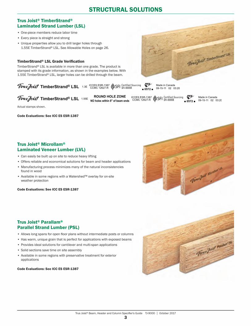
Trus Joist® TimberStrand® Laminated Strand Lumber (LSL)• One-piece members reduce labor time• Every piece is straight and strong• Unique properties allow you to drill larger holes through
1.55E TimberStrand® LSL. See Allowable Holes on page 26.
Code Evaluations: See ICC ES ESR-1387
TimberStrand® LSL Grade VerificationTimberStrand® LSL is available in more than one grade. The product is stamped with its grade information, as shown in the examples below. With 1.55E TimberStrand® LSL, larger holes can be drilled through the beam.
Actual stamps shown.
Code Evaluations: See ICC ES ESR-1387
Trus Joist® Parallam® Parallel Strand Lumber (PSL)• Allows long spans for open floor plans without intermediate posts or columns• Has warm, unique grain that is perfect for applications with exposed beams• Provides ideal solutions for cantilever and multi-span applications• Solid sections save time on site assembly• Available in some regions with preservative treatment for exterior
applications
Code Evaluations: See ICC ES ESR-1387
Trus Joist® Microllam® Laminated Veneer Lumber (LVL)• Can easily be built up on site to reduce heavy lifting• Offers reliable and economical solutions for beam and header applications• Manufacturing process minimizes many of the natural inconsistencies
found in wood• Available in some regions with a Watershed™ overlay for on-site
weather protection
Trus Joist® Beam, Header and Column Specifier's Guide TJ-9000 | October 2017
4
DESIGN PROPERTIES
Grade Width Design Property
Depth
43⁄8" 51⁄2"51⁄2"
Plank Orientation
71⁄4" 91⁄4" 91⁄2" 111⁄4" 117⁄8" 14" 16" 18" 20"
TimberStrand® LSL
1.3E 31⁄2"
Moment (ft-lbs) 1,735 2,685 1,780 4,550Shear (lbs) 4,340 5,455 1,925 7,190
Moment of Inertia (in.4) 24 49 20 111Weight (plf) 4.5 5.6 5.6 7.4
1.55E
13⁄4"
Moment (ft-lbs) 5,210 7,975 10,920 14,090Shear (lbs) 3,435 4,295 5,065 5,785
Moment of Inertia (in.4) 125 244 400 597Weight (plf) 5.2 6.5 7.7 8.8
31⁄2"
Moment (ft-lbs) 10,420 15,955 21,840 28,180Shear (lbs) 6,870 8,590 10,125 11,575
Moment of Inertia (in.4) 250 488 800 1,195Weight (plf) 10.4 13 15.3 17.5
Microllam® LVL
2.0E 13⁄4"
Moment (ft-lbs) 2,125 3,555 5,600 5,885 8,070 8,925 12,130 15,555 19,375 23,580Shear (lbs) 1,830 2,410 3,075 3,160 3,740 3,950 4,655 5,320 5,985 6,650
Moment of Inertia (in.4) 24 56 115 125 208 244 400 597 851 1,167Weight (plf) 2.8 3.7 4.7 4.8 5.7 6.1 7.1 8.2 9.2 10.2
Parallam® PSL
2.0E
31⁄2"
Moment (ft-lbs) 12,415 13,055 17,970 19,900 27,160 34,955 43,665Shear (lbs) 6,260 6,430 7,615 8,035 9,475 10,825 12,180
Moment of Inertia (in.4) 231 250 415 488 800 1,195 1,701Weight (plf) 10.1 10.4 12.3 13.0 15.3 17.5 19.7
51⁄4"
Moment (ft-lbs) 18,625 19,585 26,955 29,855 40,740 52,430 65,495Shear (lbs) 9,390 9,645 11,420 12,055 14,210 16,240 18,270
Moment of Inertia (in.4) 346 375 623 733 1,201 1,792 2,552Weight (plf) 15.2 15.6 18.5 19.5 23.0 26.3 29.5
7"
Moment (ft-lbs) 24,830 26,115 35,940 39,805 54,325 69,905 87,325Shear (lbs) 12,520 12,855 15,225 16,070 18,945 21,655 24,360
Moment of Inertia (in.4) 462 500 831 977 1,601 2,389 3,402Weight (plf) 20.2 20.8 24.6 26.0 30.6 35.0 39.4
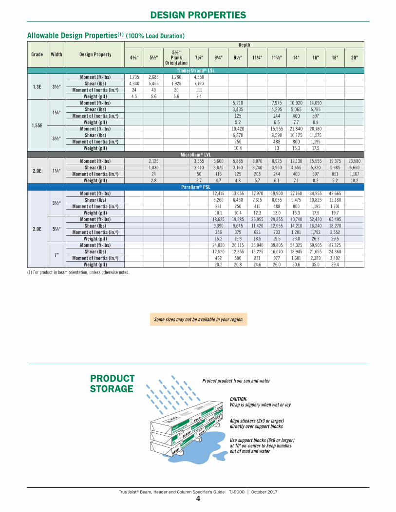
Allowable Design Properties(1) (100% Load Duration)
(1) For product in beam orientation, unless otherwise noted.
Some sizes may not be available in your region.
TrusJoist.com
888.453.8358
TrusJoist.com
888.453.8358
TrusJoist.com
888.453.8358
TrusJoist.com
888.453.8358
TrusJoist.com
888.453.8358
TrusJoist.com
888.453.8358
TrusJoist.com
888.453.8358
Use support blocks (6x6 or larger) at 10' on-center to keep bundles out of mud and water
Protect product from sun and water
CAUTION: Wrap is slippery when wet or icy
PRODUCT STORAGE
Align stickers (2x3 or larger) directly over support blocks
Trus Joist® Beam, Header and Column Specifier's Guide TJ-9000 | October 2017
5
DESIGN PROPERTIES
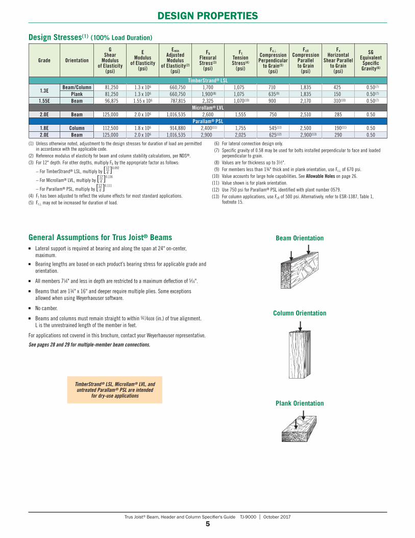
General Assumptions for Trus Joist® Beams■ Lateral support is required at bearing and along the span at 24" on-center,
maximum.■ Bearing lengths are based on each product’s bearing stress for applicable grade and
orientation.
■ All members 71⁄4" and less in depth are restricted to a maximum deflection of 5⁄16".
■ Beams that are 13⁄4" x 16" and deeper require multiple plies. Some exceptions allowed when using Weyerhaeuser software.
■ No camber.
■ Beams and columns must remain straight to within 5L2⁄4608 (in.) of true alignment. L is the unrestrained length of the member in feet.
For applications not covered in this brochure, contact your Weyerhaeuser representative.
See pages 28 and 29 for multiple-member beam connections.
Design Stresses(1) (100% Load Duration)
Grade Orientation
G Shear
Modulus of Elasticity
(psi)
E Modulus
of Elasticity (psi)
Emin Adjusted Modulus
of Elasticity(2) (psi)
Fb Flexural Stress(3)
(psi)
Ft Tension Stress(4)
(psi)
Fc⊥ Compression
Perpendicular to Grain(5)
(psi)
Fcll Compression
Parallel to Grain
(psi)
Fv Horizontal
Shear Parallel to Grain
(psi)
SG Equivalent
Specific Gravity(6)
TimberStrand® LSL
1.3EBeam/Column 81,250 1.3 x 10⁶ 660,750 1,700 1,075 710 1,835 425 0.50(7)
Plank 81,250 1.3 x 10⁶ 660,750 1,900(8) 1,075 635(9) 1,835 150 0.50(7)
1.55E Beam 96,875 1.55 x 10⁶ 787,815 2,325 1,070(10) 900 2,170 310(10) 0.50(7)
Microllam® LVL2.0E Beam 125,000 2.0 x 10⁶ 1,016,535 2,600 1,555 750 2,510 285 0.50
Parallam® PSL1.8E Column 112,500 1.8 x 10⁶ 914,880 2,400(11) 1,755 545(11) 2,500 190(11) 0.502.0E Beam 125,000 2.0 x 10⁶ 1,016,535 2,900 2,025 625(12) 2,900(13) 290 0.50
TimberStrand® LSL, Microllam® LVL, and untreated Parallam® PSL are intended
for dry-use applications
(1) Unless otherwise noted, adjustment to the design stresses for duration of load are permitted in accordance with the applicable code.
(2) Reference modulus of elasticity for beam and column stability calculations, per NDS®.(3) For 12" depth. For other depths, multiply Fb by the appropriate factor as follows:
– For TimberStrand® LSL, multiply by [ ]0.09212d
– For Microllam® LVL, multiply by [ ]0.13612d
– For Parallam® PSL, multiply by [ ]0.11112d
(4) Ft has been adjusted to reflect the volume effects for most standard applications.(5) Fc⊥ may not be increased for duration of load.
(6) For lateral connection design only. (7) Specific gravity of 0.58 may be used for bolts installed perpendicular to face and loaded
perpendicular to grain. (8) Values are for thickness up to 31⁄2". (9) For members less than 1¾" thick and in plank orientation, use Fc⊥ of 670 psi. (10) Value accounts for large hole capabilities. See Allowable Holes on page 26. (11) Value shown is for plank orientation. (12) Use 750 psi for Parallam® PSL identified with plant number 0579.(13) For column applications, use Fcll of 500 psi. Alternatively, refer to ESR-1387, Table 1,
footnote 15.
Beam Orientation
Column Orientation
Plank Orientation
Trus Joist® Beam, Header and Column Specifier's Guide TJ-9000 | October 2017
6
FLOOR LOAD TABLES
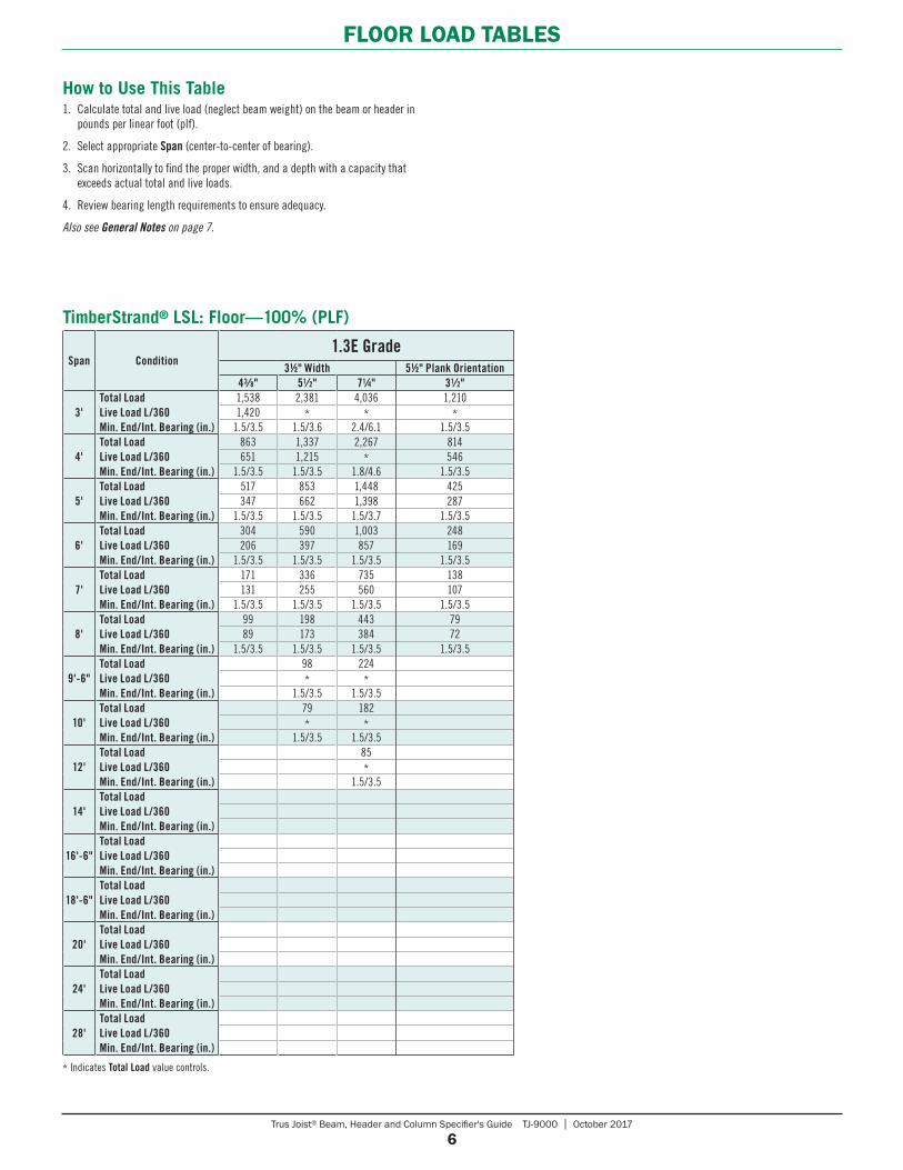
How to Use This Table1. Calculate total and live load (neglect beam weight) on the beam or header in
pounds per linear foot (plf).
2. Select appropriate Span (center-to-center of bearing).
3. Scan horizontally to find the proper width, and a depth with a capacity that exceeds actual total and live loads.
4. Review bearing length requirements to ensure adequacy.
Also see General Notes on page 7.
* Indicates Total Load value controls.
Span Condition1.3E Grade
31⁄2" Width 51⁄2" Plank Orientation43⁄8" 51⁄2" 71⁄4" 31⁄2"
3'Total LoadLive Load L/360Min. End/Int. Bearing (in.)
1,538 2,381 4,036 1,2101,420 * * *
1.5/3.5 1.5/3.6 2.4/6.1 1.5/3.5
4'Total LoadLive Load L/360Min. End/Int. Bearing (in.)
863 1,337 2,267 814651 1,215 * 546
1.5/3.5 1.5/3.5 1.8/4.6 1.5/3.5
5'Total LoadLive Load L/360Min. End/Int. Bearing (in.)
517 853 1,448 425347 662 1,398 287
1.5/3.5 1.5/3.5 1.5/3.7 1.5/3.5
6'Total LoadLive Load L/360Min. End/Int. Bearing (in.)
304 590 1,003 248206 397 857 169
1.5/3.5 1.5/3.5 1.5/3.5 1.5/3.5
7'Total LoadLive Load L/360Min. End/Int. Bearing (in.)
171 336 735 138131 255 560 107
1.5/3.5 1.5/3.5 1.5/3.5 1.5/3.5
8'Total LoadLive Load L/360Min. End/Int. Bearing (in.)
99 198 443 7989 173 384 72
1.5/3.5 1.5/3.5 1.5/3.5 1.5/3.5
9'-6"Total LoadLive Load L/360Min. End/Int. Bearing (in.)
98 224* *
1.5/3.5 1.5/3.5
10'Total LoadLive Load L/360Min. End/Int. Bearing (in.)
79 182* *
1.5/3.5 1.5/3.5
12'Total LoadLive Load L/360Min. End/Int. Bearing (in.)
85*
1.5/3.5
14'Total LoadLive Load L/360Min. End/Int. Bearing (in.)
16'-6"Total LoadLive Load L/360Min. End/Int. Bearing (in.)
18'-6"Total LoadLive Load L/360Min. End/Int. Bearing (in.)
20'Total LoadLive Load L/360Min. End/Int. Bearing (in.)
24'Total LoadLive Load L/360Min. End/Int. Bearing (in.)
28'Total LoadLive Load L/360Min. End/Int. Bearing (in.)
TimberStrand® LSL: Floor—100% (PLF)
Trus Joist® Beam, Header and Column Specifier's Guide TJ-9000 | October 2017
7
FLOOR LOAD TABLES
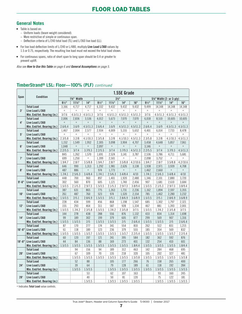
General Notes■ Table is based on: – Uniform loads (beam weight considered). – More restrictive of simple or continuous span. – Deflection criteria of L/240 total load (TL) and L/360 live load (LL).
■ For live load deflection limits of L /240 or L/480, multiply Live Load L/360 values by 1.5 or 0.75, respectively. The resulting live load must not exceed the total load shown.
■ For continuous spans, ratio of short span to long span should be 0.4 or greater to prevent uplift.
Also see How to Use this Table on page 6 and General Assumptions on page 5.
* Indicates Total Load value controls.
Span Condition1.55E Grade
13⁄4" Width 31⁄2" 51⁄4" Width (2- or 3-ply) 91⁄2" 117⁄8" 14" 91⁄2" 117⁄8" 14" 16" 91⁄2" 117⁄8" 14" 16"
3'Total LoadLive Load L/360Min. End/Int. Bearing (in.)
3,166 4,717 4,717 6,332 9,432 9,432 9,432 9,499 14,148 14,148 14,148* * * * * * * * * * *
3/7.6 4.5/11.3 4.5/11.3 3/7.6 4.5/11.3 4.5/11.3 4.5/11.3 3/7.6 4.5/11.3 4.5/11.3 4.5/11.3
4'Total LoadLive Load L/360Min. End/Int. Bearing (in.)
2,006 2,836 3,536 4,012 5,673 7,070 7,070 6,018 8,510 10,605 10,605* * * * * * * * * * *
2.6/6.4 3.6/9 4.5/11.3 2.6/6.4 3.6/9 4.5/11.3 4.5/11.3 2.6/6.4 3.6/9 4.5/11.3 4.5/11.3
5'Total LoadLive Load L/360Min. End/Int. Bearing (in.)
1,467 2,004 2,577 2,934 4,009 5,155 5,652 4,401 6,014 7,733 8,478* * * * * * * * * * *
2.3/5.8 3.2/8 4.1/10.3 2.3/5.8 3.2/8 4.1/10.3 4.5/11.3 2.3/5.8 3.2/8 4.1/10.3 4.5/11.3
6'Total LoadLive Load L/360Min. End/Int. Bearing (in.)
1,152 1,549 1,952 2,305 3,098 3,904 4,707 3,458 4,648 5,857 7,0611,048 * * 2,097 * * * 3,146 * * *
2.2/5.5 3/7.4 3.7/9.3 2.2/5.5 3/7.4 3.7/9.3 4.5/11.3 2.2/5.5 3/7.4 3.7/9.3 4.5/11.3
7'Total LoadLive Load L/360Min. End/Int. Bearing (in.)
845 1,262 1,570 1,691 2,524 3,141 3,787 2,536 3,786 4,711 5,681699 1,250 * 1,399 2,501 * * 2,098 3,752 * *
1.9/4.7 2.8/7 3.5/8.8 1.9/4.7 2.8/7 3.5/8.8 4.2/10.6 1.9/4.7 2.8/7 3.5/8.8 4.2/10.6
8'Total LoadLive Load L/360Min. End/Int. Bearing (in.)
646 990 1,313 1,292 1,981 2,626 3,138 1,938 2,971 3,939 4,708487 886 * 974 1,773 * * 1,462 2,660 * *
1.7/4.1 2.5/6.3 3.4/8.4 1.7/4.1 2.5/6.3 3.4/8.4 4/10 1.7/4.1 2.5/6.3 3.4/8.4 4/10
9'-6"Total LoadLive Load L/360Min. End/Int. Bearing (in.)
448 700 960 897 1,401 1,920 2,480 1,346 2,101 2,880 3,720302 560 870 605 1,121 1,740 2,456 907 1,681 2,610 3,684
1.5/3.5 2.1/5.3 2.9/7.3 1.5/3.5 2.1/5.3 2.9/7.3 3.8/9.4 1.5/3.5 2.1/5.3 2.9/7.3 3.8/9.4
10'Total LoadLive Load L/360Min. End/Int. Bearing (in.)
387 631 865 775 1,263 1,731 2,236 1,162 1,894 2,597 3,355261 487 760 523 974 1,520 2,154 785 1,462 2,280 3,232
1.5/3.5 2/5.1 2.8/6.9 1.5/3.5 2/5.1 2.8/6.9 3.6/8.9 1.5/3.5 2/5.1 2.8/6.9 3.6/8.9
12'Total LoadLive Load L/360Min. End/Int. Bearing (in.)
228 434 599 456 868 1,198 1,547 685 1,302 1,797 2,321155 293 464 311 587 928 1,334 467 881 1,393 2,001
1.5/3.5 1.7/4.2 2.3/5.8 1.5/3.5 1.7/4.2 2.3/5.8 3/7.5 1.5/3.5 1.7/4.2 2.3/5.8 3/7.5
14'Total LoadLive Load L/360Min. End/Int. Bearing (in.)
144 278 438 288 556 876 1,132 433 834 1,314 1,69899 189 302 199 379 605 877 299 569 907 1,316
1.5/3.5 1.5/3.5 2/5 1.5/3.5 1.5/3.5 2/5 2.6/6.4 1.5/3.5 1.5/3.5 2/5 2.6/6.4
16'-6"Total LoadLive Load L/360Min. End/Int. Bearing (in.)
87 170 277 174 341 554 810 262 512 831 1,21561 118 189 123 236 379 555 185 354 569 832
1.5/3.5 1.5/3.5 1.5/3.7 1.5/3.5 1.5/3.5 1.5/3.7 2.2/5.4 1.5/3.5 1.5/3.5 1.5/3.7 2.2/5.4
18'-6"Total LoadLive Load L/360Min. End/Int. Bearing (in.)
60 120 197 121 241 395 584 182 362 592 87644 84 136 88 169 273 401 132 254 410 601
1.5/3.5 1.5/3.5 1.5/3.5 1.5/3.5 1.5/3.5 1.5/3.5 1.8/4.4 1.5/3.5 1.5/3.5 1.5/3.5 1.8/4.4
20'Total LoadLive Load L/360Min. End/Int. Bearing (in.)
94 156 94 189 312 463 142 284 468 69567 109 70 135 218 320 105 202 327 481
1.5/3.5 1.5/3.5 1.5/3.5 1.5/3.5 1.5/3.5 1.5/3.8 1.5/3.5 1.5/3.5 1.5/3.5 1.5/3.8
24'Total LoadLive Load L/360Min. End/Int. Bearing (in.)
52 88 105 177 266 76 158 265 40039 64 79 128 189 61 118 192 284
1.5/3.5 1.5/3.5 1.5/3.5 1.5/3.5 1.5/3.5 1.5/3.5 1.5/3.5 1.5/3.5 1.5/3.5
28'Total LoadLive Load L/360Min. End/Int. Bearing (in.)
53 62 107 163 93 160 24540 50 81 120 75 122 181
1.5/3.5 1.5/3.5 1.5/3.5 1.5/3.5 1.5/3.5 1.5/3.5 1.5/3.5
TimberStrand® LSL: Floor—100% (PLF) continued
Trus Joist® Beam, Header and Column Specifier's Guide TJ-9000 | October 2017
8
FLOOR LOAD TABLES
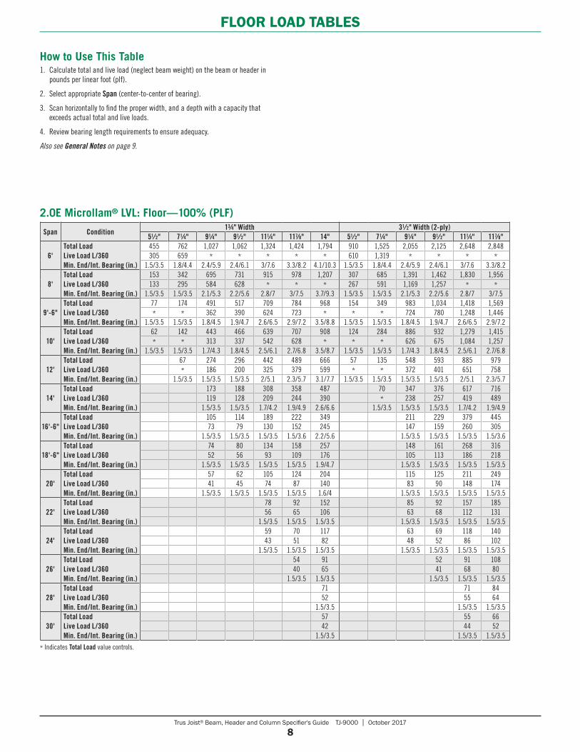
Span Condition13⁄4" Width 31⁄2" Width (2-ply)
51⁄2" 71⁄4" 91⁄4" 91⁄2" 111⁄4" 117⁄8" 14" 51⁄2" 71⁄4" 91⁄4" 91⁄2" 111⁄4" 117⁄8"
6'Total LoadLive Load L/360Min. End/Int. Bearing (in.)
455 762 1,027 1,062 1,324 1,424 1,794 910 1,525 2,055 2,125 2,648 2,848305 659 * * * * * 610 1,319 * * * *
1.5/3.5 1.8/4.4 2.4/5.9 2.4/6.1 3/7.6 3.3/8.2 4.1/10.3 1.5/3.5 1.8/4.4 2.4/5.9 2.4/6.1 3/7.6 3.3/8.2
8'Total LoadLive Load L/360Min. End/Int. Bearing (in.)
153 342 695 731 915 978 1,207 307 685 1,391 1,462 1,830 1,956133 295 584 628 * * * 267 591 1,169 1,257 * *
1.5/3.5 1.5/3.5 2.1/5.3 2.2/5.6 2.8/7 3/7.5 3.7/9.3 1.5/3.5 1.5/3.5 2.1/5.3 2.2/5.6 2.8/7 3/7.5
9'-6"Total LoadLive Load L/360Min. End/Int. Bearing (in.)
77 174 491 517 709 784 968 154 349 983 1,034 1,418 1,569* * 362 390 624 723 * * * 724 780 1,248 1,446
1.5/3.5 1.5/3.5 1.8/4.5 1.9/4.7 2.6/6.5 2.9/7.2 3.5/8.8 1.5/3.5 1.5/3.5 1.8/4.5 1.9/4.7 2.6/6.5 2.9/7.2
10'Total LoadLive Load L/360Min. End/Int. Bearing (in.)
62 142 443 466 639 707 908 124 284 886 932 1,279 1,415* * 313 337 542 628 * * * 626 675 1,084 1,257
1.5/3.5 1.5/3.5 1.7/4.3 1.8/4.5 2.5/6.1 2.7/6.8 3.5/8.7 1.5/3.5 1.5/3.5 1.7/4.3 1.8/4.5 2.5/6.1 2.7/6.8
12'Total LoadLive Load L/360Min. End/Int. Bearing (in.)
67 274 296 442 489 666 57 135 548 593 885 979* 186 200 325 379 599 * * 372 401 651 758
1.5/3.5 1.5/3.5 1.5/3.5 2/5.1 2.3/5.7 3.1/7.7 1.5/3.5 1.5/3.5 1.5/3.5 1.5/3.5 2/5.1 2.3/5.7
14'Total LoadLive Load L/360Min. End/Int. Bearing (in.)
173 188 308 358 487 70 347 376 617 716119 128 209 244 390 * 238 257 419 489
1.5/3.5 1.5/3.5 1.7/4.2 1.9/4.9 2.6/6.6 1.5/3.5 1.5/3.5 1.5/3.5 1.7/4.2 1.9/4.9
16'-6"Total LoadLive Load L/360Min. End/Int. Bearing (in.)
105 114 189 222 349 211 229 379 44573 79 130 152 245 147 159 260 305
1.5/3.5 1.5/3.5 1.5/3.5 1.5/3.6 2.2/5.6 1.5/3.5 1.5/3.5 1.5/3.5 1.5/3.6
18'-6"Total LoadLive Load L/360Min. End/Int. Bearing (in.)
74 80 134 158 257 148 161 268 31652 56 93 109 176 105 113 186 218
1.5/3.5 1.5/3.5 1.5/3.5 1.5/3.5 1.9/4.7 1.5/3.5 1.5/3.5 1.5/3.5 1.5/3.5
20'Total LoadLive Load L/360Min. End/Int. Bearing (in.)
57 62 105 124 204 115 125 211 24941 45 74 87 140 83 90 148 174
1.5/3.5 1.5/3.5 1.5/3.5 1.5/3.5 1.6/4 1.5/3.5 1.5/3.5 1.5/3.5 1.5/3.5
22'Total LoadLive Load L/360Min. End/Int. Bearing (in.)
78 92 152 85 92 157 18556 65 106 63 68 112 131
1.5/3.5 1.5/3.5 1.5/3.5 1.5/3.5 1.5/3.5 1.5/3.5 1.5/3.5
24'Total LoadLive Load L/360Min. End/Int. Bearing (in.)
59 70 117 63 69 118 14043 51 82 48 52 86 102
1.5/3.5 1.5/3.5 1.5/3.5 1.5/3.5 1.5/3.5 1.5/3.5 1.5/3.5
26'Total LoadLive Load L/360Min. End/Int. Bearing (in.)
54 91 52 91 10840 65 41 68 80
1.5/3.5 1.5/3.5 1.5/3.5 1.5/3.5 1.5/3.5
28'Total LoadLive Load L/360Min. End/Int. Bearing (in.)
71 71 8452 55 64
1.5/3.5 1.5/3.5 1.5/3.5
30'Total LoadLive Load L/360Min. End/Int. Bearing (in.)
57 55 6642 44 52
1.5/3.5 1.5/3.5 1.5/3.5
* Indicates Total Load value controls.
2.0E Microllam® LVL: Floor—100% (PLF)
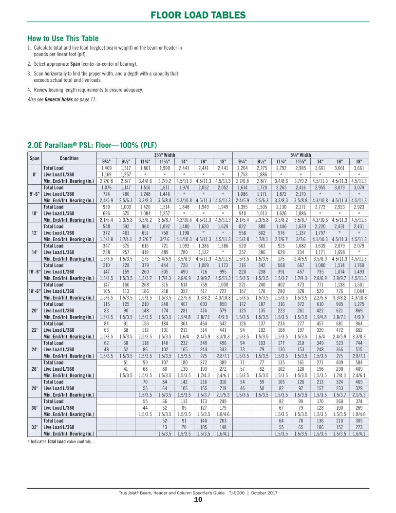
How to Use This Table1. Calculate total and live load (neglect beam weight) on the beam or header in
pounds per linear foot (plf).
2. Select appropriate Span (center-to-center of bearing).
3. Scan horizontally to find the proper width, and a depth with a capacity that exceeds actual total and live loads.
4. Review bearing length requirements to ensure adequacy.
Also see General Notes on page 9.
Trus Joist® Beam, Header and Column Specifier's Guide TJ-9000 | October 2017
9
FLOOR LOAD TABLES
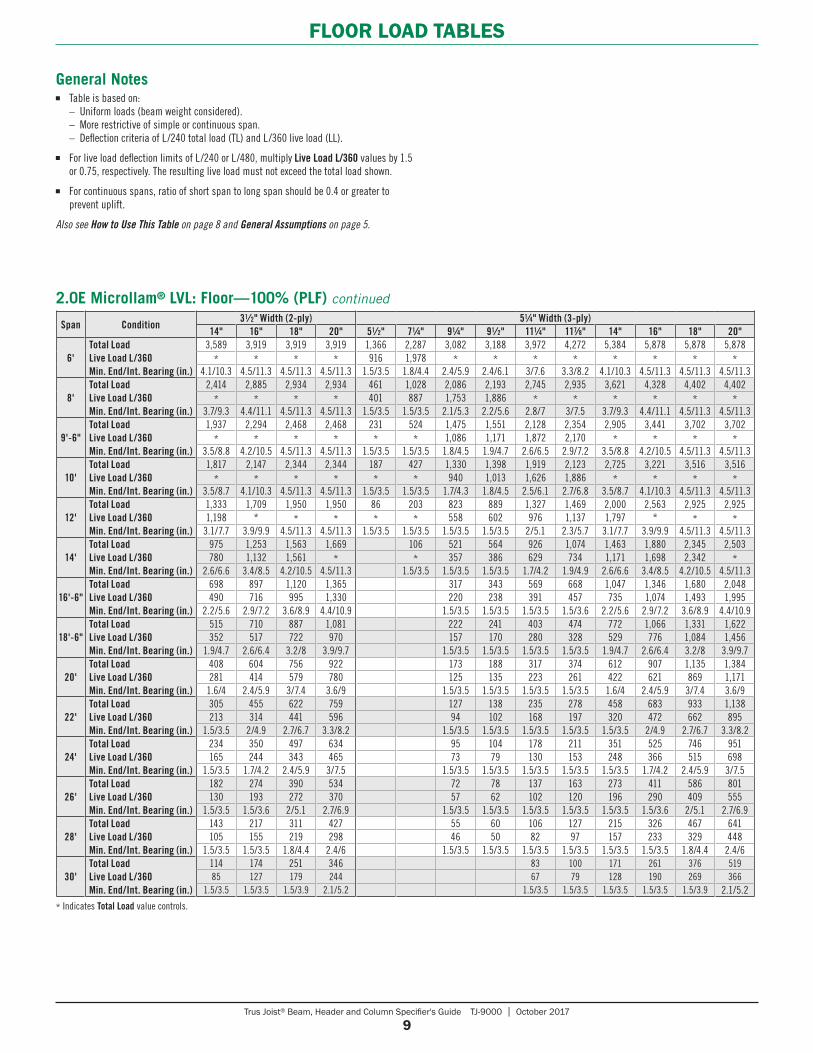
General Notes■ Table is based on: – Uniform loads (beam weight considered). – More restrictive of simple or continuous span. – Deflection criteria of L/240 total load (TL) and L/360 live load (LL).
■ For live load deflection limits of L/240 or L/480, multiply Live Load L/360 values by 1.5 or 0.75, respectively. The resulting live load must not exceed the total load shown.
■ For continuous spans, ratio of short span to long span should be 0.4 or greater to prevent uplift.
Also see How to Use This Table on page 8 and General Assumptions on page 5.
Span Condition31⁄2" Width (2-ply) 51⁄4" Width (3-ply)
14" 16" 18" 20" 51⁄2" 71⁄4" 91⁄4" 91⁄2" 111⁄4" 117⁄8" 14" 16" 18" 20"
6'Total LoadLive Load L/360Min. End/Int. Bearing (in.)
3,589 3,919 3,919 3,919 1,366 2,287 3,082 3,188 3,972 4,272 5,384 5,878 5,878 5,878* * * * 916 1,978 * * * * * * * *
4.1/10.3 4.5/11.3 4.5/11.3 4.5/11.3 1.5/3.5 1.8/4.4 2.4/5.9 2.4/6.1 3/7.6 3.3/8.2 4.1/10.3 4.5/11.3 4.5/11.3 4.5/11.3
8'Total LoadLive Load L/360Min. End/Int. Bearing (in.)
2,414 2,885 2,934 2,934 461 1,028 2,086 2,193 2,745 2,935 3,621 4,328 4,402 4,402* * * * 401 887 1,753 1,886 * * * * * *
3.7/9.3 4.4/11.1 4.5/11.3 4.5/11.3 1.5/3.5 1.5/3.5 2.1/5.3 2.2/5.6 2.8/7 3/7.5 3.7/9.3 4.4/11.1 4.5/11.3 4.5/11.3
9'-6"Total LoadLive Load L/360Min. End/Int. Bearing (in.)
1,937 2,294 2,468 2,468 231 524 1,475 1,551 2,128 2,354 2,905 3,441 3,702 3,702* * * * * * 1,086 1,171 1,872 2,170 * * * *
3.5/8.8 4.2/10.5 4.5/11.3 4.5/11.3 1.5/3.5 1.5/3.5 1.8/4.5 1.9/4.7 2.6/6.5 2.9/7.2 3.5/8.8 4.2/10.5 4.5/11.3 4.5/11.3
10'Total LoadLive Load L/360Min. End/Int. Bearing (in.)
1,817 2,147 2,344 2,344 187 427 1,330 1,398 1,919 2,123 2,725 3,221 3,516 3,516* * * * * * 940 1,013 1,626 1,886 * * * *
3.5/8.7 4.1/10.3 4.5/11.3 4.5/11.3 1.5/3.5 1.5/3.5 1.7/4.3 1.8/4.5 2.5/6.1 2.7/6.8 3.5/8.7 4.1/10.3 4.5/11.3 4.5/11.3
12'Total LoadLive Load L/360Min. End/Int. Bearing (in.)
1,333 1,709 1,950 1,950 86 203 823 889 1,327 1,469 2,000 2,563 2,925 2,9251,198 * * * * * 558 602 976 1,137 1,797 * * *
3.1/7.7 3.9/9.9 4.5/11.3 4.5/11.3 1.5/3.5 1.5/3.5 1.5/3.5 1.5/3.5 2/5.1 2.3/5.7 3.1/7.7 3.9/9.9 4.5/11.3 4.5/11.3
14'Total LoadLive Load L/360Min. End/Int. Bearing (in.)
975 1,253 1,563 1,669 106 521 564 926 1,074 1,463 1,880 2,345 2,503780 1,132 1,561 * * 357 386 629 734 1,171 1,698 2,342 *
2.6/6.6 3.4/8.5 4.2/10.5 4.5/11.3 1.5/3.5 1.5/3.5 1.5/3.5 1.7/4.2 1.9/4.9 2.6/6.6 3.4/8.5 4.2/10.5 4.5/11.3
16'-6"Total LoadLive Load L/360Min. End/Int. Bearing (in.)
698 897 1,120 1,365 317 343 569 668 1,047 1,346 1,680 2,048490 716 995 1,330 220 238 391 457 735 1,074 1,493 1,995
2.2/5.6 2.9/7.2 3.6/8.9 4.4/10.9 1.5/3.5 1.5/3.5 1.5/3.5 1.5/3.6 2.2/5.6 2.9/7.2 3.6/8.9 4.4/10.9
18'-6"Total LoadLive Load L/360Min. End/Int. Bearing (in.)
515 710 887 1,081 222 241 403 474 772 1,066 1,331 1,622352 517 722 970 157 170 280 328 529 776 1,084 1,456
1.9/4.7 2.6/6.4 3.2/8 3.9/9.7 1.5/3.5 1.5/3.5 1.5/3.5 1.5/3.5 1.9/4.7 2.6/6.4 3.2/8 3.9/9.7
20'Total LoadLive Load L/360Min. End/Int. Bearing (in.)
408 604 756 922 173 188 317 374 612 907 1,135 1,384281 414 579 780 125 135 223 261 422 621 869 1,171
1.6/4 2.4/5.9 3/7.4 3.6/9 1.5/3.5 1.5/3.5 1.5/3.5 1.5/3.5 1.6/4 2.4/5.9 3/7.4 3.6/9
22'Total LoadLive Load L/360Min. End/Int. Bearing (in.)
305 455 622 759 127 138 235 278 458 683 933 1,138213 314 441 596 94 102 168 197 320 472 662 895
1.5/3.5 2/4.9 2.7/6.7 3.3/8.2 1.5/3.5 1.5/3.5 1.5/3.5 1.5/3.5 1.5/3.5 2/4.9 2.7/6.7 3.3/8.2
24'Total LoadLive Load L/360Min. End/Int. Bearing (in.)
234 350 497 634 95 104 178 211 351 525 746 951165 244 343 465 73 79 130 153 248 366 515 698
1.5/3.5 1.7/4.2 2.4/5.9 3/7.5 1.5/3.5 1.5/3.5 1.5/3.5 1.5/3.5 1.5/3.5 1.7/4.2 2.4/5.9 3/7.5
26'Total LoadLive Load L/360Min. End/Int. Bearing (in.)
182 274 390 534 72 78 137 163 273 411 586 801130 193 272 370 57 62 102 120 196 290 409 555
1.5/3.5 1.5/3.6 2/5.1 2.7/6.9 1.5/3.5 1.5/3.5 1.5/3.5 1.5/3.5 1.5/3.5 1.5/3.6 2/5.1 2.7/6.9
28'Total LoadLive Load L/360Min. End/Int. Bearing (in.)
143 217 311 427 55 60 106 127 215 326 467 641105 155 219 298 46 50 82 97 157 233 329 448
1.5/3.5 1.5/3.5 1.8/4.4 2.4/6 1.5/3.5 1.5/3.5 1.5/3.5 1.5/3.5 1.5/3.5 1.5/3.5 1.8/4.4 2.4/6
30'Total LoadLive Load L/360Min. End/Int. Bearing (in.)
114 174 251 346 83 100 171 261 376 51985 127 179 244 67 79 128 190 269 366
1.5/3.5 1.5/3.5 1.5/3.9 2.1/5.2 1.5/3.5 1.5/3.5 1.5/3.5 1.5/3.5 1.5/3.9 2.1/5.2
2.0E Microllam® LVL: Floor—100% (PLF) continued
* Indicates Total Load value controls.
Trus Joist® Beam, Header and Column Specifier's Guide TJ-9000 | October 2017
10
FLOOR LOAD TABLES
Span Condition31⁄2" Width 51⁄4" Width
91⁄4" 91⁄2" 111⁄4" 117⁄8" 14" 16" 18" 91⁄4" 91⁄2" 111⁄4" 117⁄8" 14" 16" 18"
8'Total LoadLive Load L/360Min. End/Int. Bearing (in.)
1,469 1,517 1,861 1,990 2,441 2,441 2,441 2,204 2,275 2,792 2,985 3,661 3,661 3,6611,169 1,257 * * * * * 1,753 1,886 * * * * *
2.7/6.8 2.8/7 3.4/8.6 3.7/9.2 4.5/11.3 4.5/11.3 4.5/11.3 2.7/6.8 2.8/7 3.4/8.6 3.7/9.2 4.5/11.3 4.5/11.3 4.5/11.3
9'-6"Total LoadLive Load L/360Min. End/Int. Bearing (in.)
1,076 1,147 1,510 1,611 1,970 2,052 2,052 1,614 1,720 2,265 2,416 2,955 3,079 3,079724 780 1,248 1,446 * * * 1,086 1,171 1,872 2,170 * * *
2.4/5.9 2.5/6.3 3.3/8.3 3.5/8.8 4.3/10.8 4.5/11.3 4.5/11.3 2.4/5.9 2.5/6.3 3.3/8.3 3.5/8.8 4.3/10.8 4.5/11.3 4.5/11.3
10'Total LoadLive Load L/360Min. End/Int. Bearing (in.)
930 1,003 1,420 1,514 1,848 1,949 1,949 1,395 1,505 2,130 2,271 2,772 2,923 2,923626 675 1,084 1,257 * * * 940 1,013 1,626 1,886 * * *
2.1/5.4 2.3/5.8 3.3/8.2 3.5/8.7 4.3/10.6 4.5/11.3 4.5/11.3 2.1/5.4 2.3/5.8 3.3/8.2 3.5/8.7 4.3/10.6 4.5/11.3 4.5/11.3
12'Total LoadLive Load L/360Min. End/Int. Bearing (in.)
548 592 964 1,092 1,480 1,620 1,620 822 888 1,446 1,639 2,220 2,431 2,431372 401 651 758 1,198 * * 558 602 976 1,137 1,797 * *
1.5/3.8 1.7/4.1 2.7/6.7 3/7.6 4.1/10.3 4.5/11.3 4.5/11.3 1.5/3.8 1.7/4.1 2.7/6.7 3/7.6 4.1/10.3 4.5/11.3 4.5/11.3
14'Total LoadLive Load L/360Min. End/Int. Bearing (in.)
347 375 616 721 1,093 1,386 1,386 520 563 925 1,082 1,639 2,079 2,079238 257 419 489 780 1,132 * 357 386 629 734 1,171 1,698 *
1.5/3.5 1.5/3.5 2/5 2.4/5.9 3.5/8.9 4.5/11.3 4.5/11.3 1.5/3.5 1.5/3.5 2/5 2.4/5.9 3.5/8.9 4.5/11.3 4.5/11.3
16'-6"Total LoadLive Load L/360Min. End/Int. Bearing (in.)
210 228 379 444 720 1,009 1,173 316 342 568 667 1,080 1,514 1,760147 159 260 305 490 716 995 220 238 391 457 735 1,074 1,493
1.5/3.5 1.5/3.5 1.5/3.7 1.7/4.3 2.8/6.9 3.9/9.7 4.5/11.3 1.5/3.5 1.5/3.5 1.5/3.7 1.7/4.3 2.8/6.9 3.9/9.7 4.5/11.3
18'-6"Total LoadLive Load L/360Min. End/Int. Bearing (in.)
147 160 268 315 514 759 1,000 221 240 402 473 771 1,138 1,501105 113 186 218 352 517 722 157 170 280 328 529 776 1,084
1.5/3.5 1.5/3.5 1.5/3.5 1.5/3.5 2.2/5.6 3.3/8.2 4.3/10.8 1.5/3.5 1.5/3.5 1.5/3.5 1.5/3.5 2.2/5.6 3.3/8.2 4.3/10.8
20'Total LoadLive Load L/360Min. End/Int. Bearing (in.)
115 125 210 248 407 603 850 172 187 316 372 610 905 1,27583 90 148 174 281 414 579 125 135 223 261 422 621 869
1.5/3.5 1.5/3.5 1.5/3.5 1.5/3.5 1.9/4.8 2.8/7.1 4/9.9 1.5/3.5 1.5/3.5 1.5/3.5 1.5/3.5 1.9/4.8 2.8/7.1 4/9.9
22'Total LoadLive Load L/360Min. End/Int. Bearing (in.)
84 91 156 184 304 454 642 126 137 234 277 457 681 96463 68 112 131 213 314 441 94 102 168 197 320 472 662
1.5/3.5 1.5/3.5 1.5/3.5 1.5/3.5 1.6/4 2.4/5.9 3.3/8.3 1.5/3.5 1.5/3.5 1.5/3.5 1.5/3.5 1.6/4 2.4/5.9 3.3/8.3
24'Total LoadLive Load L/360Min. End/Int. Bearing (in.)
62 68 118 140 232 349 496 94 103 177 210 349 523 74448 52 86 102 165 244 343 73 79 130 153 248 366 515
1.5/3.5 1.5/3.5 1.5/3.5 1.5/3.5 1.5/3.5 2/5 2.8/7.1 1.5/3.5 1.5/3.5 1.5/3.5 1.5/3.5 1.5/3.5 2/5 2.8/7.1
26'Total LoadLive Load L/360Min. End/Int. Bearing (in.)
51 90 107 180 272 389 71 77 135 161 271 409 58441 68 80 130 193 272 57 62 102 120 196 290 409
1.5/3.5 1.5/3.5 1.5/3.5 1.5/3.5 1.7/4.3 2.4/6.1 1.5/3.5 1.5/3.5 1.5/3.5 1.5/3.5 1.5/3.5 1.7/4.3 2.4/6.1
28'Total LoadLive Load L/360Min. End/Int. Bearing (in.)
70 84 142 216 310 54 59 105 126 213 324 46555 64 105 155 219 46 50 82 97 157 233 329
1.5/3.5 1.5/3.5 1.5/3.5 1.5/3.7 2.1/5.3 1.5/3.5 1.5/3.5 1.5/3.5 1.5/3.5 1.5/3.5 1.5/3.7 2.1/5.3
30'Total LoadLive Load L/360Min. End/Int. Bearing (in.)
55 66 113 173 249 82 99 170 260 37444 52 85 127 179 67 79 128 190 269
1.5/3.5 1.5/3.5 1.5/3.5 1.5/3.5 1.8/4.6 1.5/3.5 1.5/3.5 1.5/3.5 1.5/3.5 1.8/4.6
32'Total LoadLive Load L/360Min. End/Int. Bearing (in.)
52 91 140 203 64 78 136 210 30543 70 105 148 55 65 106 157 223
1.5/3.5 1.5/3.5 1.5/3.5 1.6/4.1 1.5/3.5 1.5/3.5 1.5/3.5 1.5/3.5 1.6/4.1
2.0E Parallam® PSL: Floor—100% (PLF)
* Indicates Total Load value controls.
How to Use This Table1. Calculate total and live load (neglect beam weight) on the beam or header in
pounds per linear foot (plf).
2. Select appropriate Span (center-to-center of bearing).
3. Scan horizontally to find the proper width, and a depth with a capacity that exceeds actual total and live loads.
4. Review bearing length requirements to ensure adequacy.
Also see General Notes on page 11.
Trus Joist® Beam, Header and Column Specifier's Guide TJ-9000 | October 2017
11
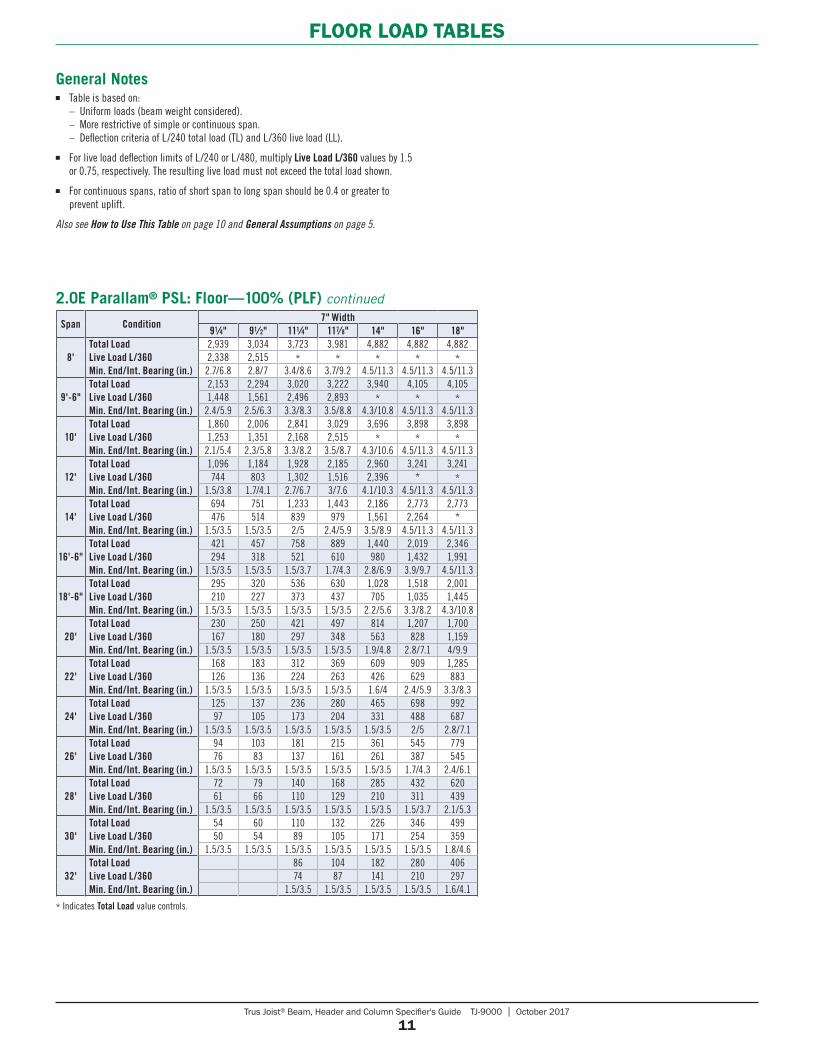
FLOOR LOAD TABLES
Span Condition7" Width
91⁄4" 91⁄2" 111⁄4" 117⁄8" 14" 16" 18"
8'Total LoadLive Load L/360Min. End/Int. Bearing (in.)
2,939 3,034 3,723 3,981 4,882 4,882 4,8822,338 2,515 * * * * *2.7/6.8 2.8/7 3.4/8.6 3.7/9.2 4.5/11.3 4.5/11.3 4.5/11.3
9'-6"Total LoadLive Load L/360Min. End/Int. Bearing (in.)
2,153 2,294 3,020 3,222 3,940 4,105 4,1051,448 1,561 2,496 2,893 * * *
2.4/5.9 2.5/6.3 3.3/8.3 3.5/8.8 4.3/10.8 4.5/11.3 4.5/11.3
10'Total LoadLive Load L/360Min. End/Int. Bearing (in.)
1,860 2,006 2,841 3,029 3,696 3,898 3,8981,253 1,351 2,168 2,515 * * *
2.1/5.4 2.3/5.8 3.3/8.2 3.5/8.7 4.3/10.6 4.5/11.3 4.5/11.3
12'Total LoadLive Load L/360Min. End/Int. Bearing (in.)
1,096 1,184 1,928 2,185 2,960 3,241 3,241744 803 1,302 1,516 2,396 * *
1.5/3.8 1.7/4.1 2.7/6.7 3/7.6 4.1/10.3 4.5/11.3 4.5/11.3
14'Total LoadLive Load L/360Min. End/Int. Bearing (in.)
694 751 1,233 1,443 2,186 2,773 2,773476 514 839 979 1,561 2,264 *
1.5/3.5 1.5/3.5 2/5 2.4/5.9 3.5/8.9 4.5/11.3 4.5/11.3
16'-6"Total LoadLive Load L/360Min. End/Int. Bearing (in.)
421 457 758 889 1,440 2,019 2,346294 318 521 610 980 1,432 1,991
1.5/3.5 1.5/3.5 1.5/3.7 1.7/4.3 2.8/6.9 3.9/9.7 4.5/11.3
18'-6"Total LoadLive Load L/360Min. End/Int. Bearing (in.)
295 320 536 630 1,028 1,518 2,001210 227 373 437 705 1,035 1,445
1.5/3.5 1.5/3.5 1.5/3.5 1.5/3.5 2.2/5.6 3.3/8.2 4.3/10.8
20'Total LoadLive Load L/360Min. End/Int. Bearing (in.)
230 250 421 497 814 1,207 1,700167 180 297 348 563 828 1,159
1.5/3.5 1.5/3.5 1.5/3.5 1.5/3.5 1.9/4.8 2.8/7.1 4/9.9
22'Total LoadLive Load L/360Min. End/Int. Bearing (in.)
168 183 312 369 609 909 1,285126 136 224 263 426 629 883
1.5/3.5 1.5/3.5 1.5/3.5 1.5/3.5 1.6/4 2.4/5.9 3.3/8.3
24'Total LoadLive Load L/360Min. End/Int. Bearing (in.)
125 137 236 280 465 698 99297 105 173 204 331 488 687
1.5/3.5 1.5/3.5 1.5/3.5 1.5/3.5 1.5/3.5 2/5 2.8/7.1
26'Total LoadLive Load L/360Min. End/Int. Bearing (in.)
94 103 181 215 361 545 77976 83 137 161 261 387 545
1.5/3.5 1.5/3.5 1.5/3.5 1.5/3.5 1.5/3.5 1.7/4.3 2.4/6.1
28'Total LoadLive Load L/360Min. End/Int. Bearing (in.)
72 79 140 168 285 432 62061 66 110 129 210 311 439
1.5/3.5 1.5/3.5 1.5/3.5 1.5/3.5 1.5/3.5 1.5/3.7 2.1/5.3
30'Total LoadLive Load L/360Min. End/Int. Bearing (in.)
54 60 110 132 226 346 49950 54 89 105 171 254 359
1.5/3.5 1.5/3.5 1.5/3.5 1.5/3.5 1.5/3.5 1.5/3.5 1.8/4.6
32'Total LoadLive Load L/360Min. End/Int. Bearing (in.)
86 104 182 280 40674 87 141 210 297
1.5/3.5 1.5/3.5 1.5/3.5 1.5/3.5 1.6/4.1
General Notes■ Table is based on: – Uniform loads (beam weight considered). – More restrictive of simple or continuous span. – Deflection criteria of L/240 total load (TL) and L/360 live load (LL).
■ For live load deflection limits of L/240 or L/480, multiply Live Load L/360 values by 1.5 or 0.75, respectively. The resulting live load must not exceed the total load shown.
■ For continuous spans, ratio of short span to long span should be 0.4 or greater to prevent uplift.
Also see How to Use This Table on page 10 and General Assumptions on page 5.
* Indicates Total Load value controls.
2.0E Parallam® PSL: Floor—100% (PLF) continued

Trus Joist® Beam, Header and Column Specifier's Guide TJ-9000 | October 2017
12
SNOW ROOF LOAD TABLES
Span Condition1.3E Grade
31⁄2" Width 51⁄2" Plank Orientation43⁄8" 51⁄2" 71⁄4" 31⁄2"
3'Total LoadDeflection L/240 / L/360Min. End/Int. Bearing (in.)
1,769 2,739 4,643 1,392*/1,420 */2,547 */* */1,2241.5/3.5 1.7/4.1 2.8/7 1.5/3.5
4'Total LoadDeflection L/240 / L/360Min. End/Int. Bearing (in.)
993 1,538 2,608 996977/651 */1,215 */2,476 820/5461.5/3.5 1.5/3.5 2.1/5.3 1.5/3.5
5'Total LoadDeflection L/240 / L/360Min. End/Int. Bearing (in.)
634 982 1,666 533521/347 */662 */1,398 431/2871.5/3.5 1.5/3.5 1.7/4.2 1.5/3.5
6'Total LoadDeflection L/240 / L/360Min. End/Int. Bearing (in.)
317 614 1,155 258309/206 595/397 */857 253/1691.5/3.5 1.5/3.5 1.5/3.5 1.5/3.5
7'Total LoadDeflection L/240 / L/360Min. End/Int. Bearing (in.)
171 336 742 138*/131 */255 */560 */107
1.5/3.5 1.5/3.5 1.5/3.5 1.5/3.5
8'Total LoadDeflection L/240 / L/360Min. End/Int. Bearing (in.)
99 198 443 79*/89 */173 */384 */72
1.5/3.5 1.5/3.5 1.5/3.5 1.5/3.5
9'-6"Total LoadDeflection L/240 / L/360Min. End/Int. Bearing (in.)
98 224*/* */*
1.5/3.5 1.5/3.5
10'Total LoadDeflection L/240 / L/360Min. End/Int. Bearing (in.)
79 182*/* */*
1.5/3.5 1.5/3.5
12'Total LoadDeflection L/240 / L/360Min. End/Int. Bearing (in.)
85*/*
1.5/3.5
14'Total LoadDeflection L/240 / L/360Min. End/Int. Bearing (in.)
16'-6"Total LoadDeflection L/240 / L/360Min. End/Int. Bearing (in.)
18'-6"Total LoadDeflection L/240 / L/360Min. End/Int. Bearing (in.)
20'Total LoadDeflection L/240 / L/360Min. End/Int. Bearing (in.)
24'Total LoadDeflection L/240 / L/360Min. End/Int. Bearing (in.)
28'Total LoadDeflection L/240 / L/360 Min. End/Int. Bearing (in.)
TimberStrand® LSL: Roof—Snow Load Area 115% (PLF)
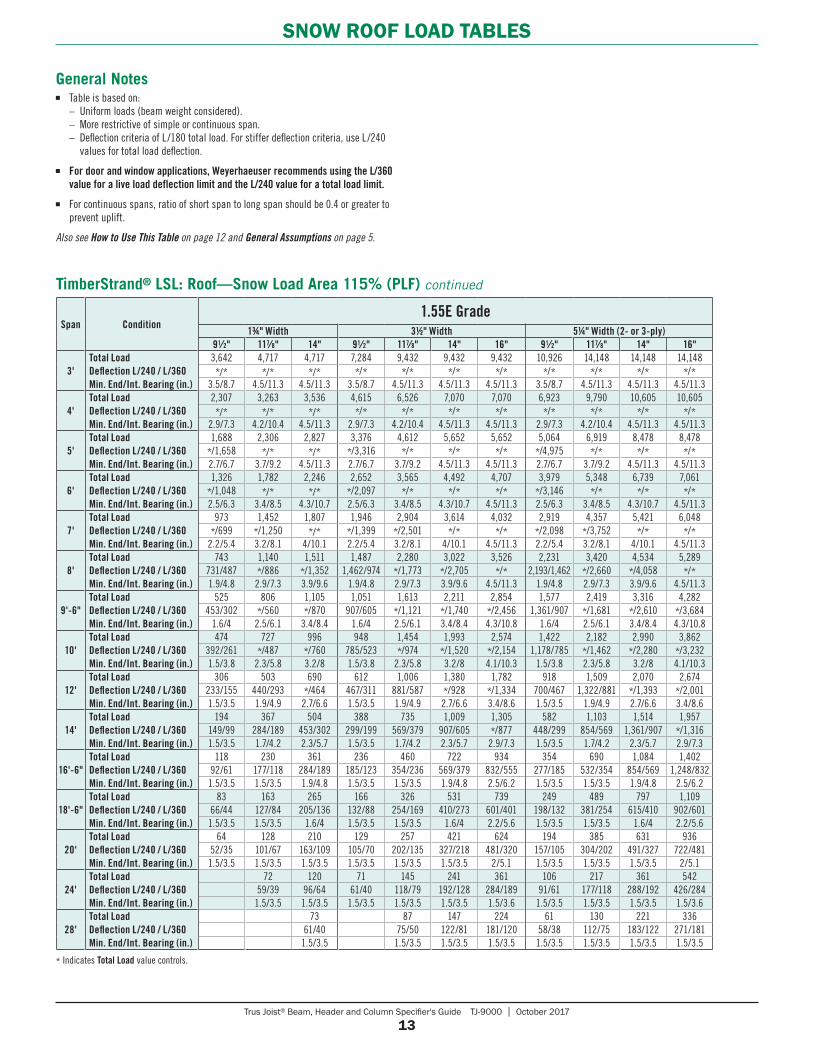
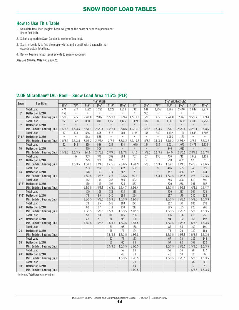
How to Use This Table1. Calculate total load (neglect beam weight) on the beam or header in pounds per
linear foot (plf).
2. Select appropriate Span (center-to-center of bearing).
3. Scan horizontally to find the proper width, and a depth with a capacity that exceeds actual total load.
4. Review bearing length requirements to ensure adequacy.
Also see General Notes on page 13.
* Indicates Total Load value controls.
Trus Joist® Beam, Header and Column Specifier's Guide TJ-9000 | October 2017
13
SNOW ROOF LOAD TABLES
Span Condition1.55E Grade
13⁄4" Width 31⁄2" Width 51⁄4" Width (2- or 3-ply)91⁄2" 117⁄8" 14" 91⁄2" 117⁄8" 14" 16" 91⁄2" 117⁄8" 14" 16"
3'Total LoadDeflection L/240 / L/360Min. End/Int. Bearing (in.)
3,642 4,717 4,717 7,284 9,432 9,432 9,432 10,926 14,148 14,148 14,148*/* */* */* */* */* */* */* */* */* */* */*
3.5/8.7 4.5/11.3 4.5/11.3 3.5/8.7 4.5/11.3 4.5/11.3 4.5/11.3 3.5/8.7 4.5/11.3 4.5/11.3 4.5/11.3
4'Total LoadDeflection L/240 / L/360Min. End/Int. Bearing (in.)
2,307 3,263 3,536 4,615 6,526 7,070 7,070 6,923 9,790 10,605 10,605*/* */* */* */* */* */* */* */* */* */* */*
2.9/7.3 4.2/10.4 4.5/11.3 2.9/7.3 4.2/10.4 4.5/11.3 4.5/11.3 2.9/7.3 4.2/10.4 4.5/11.3 4.5/11.3
5'Total LoadDeflection L/240 / L/360Min. End/Int. Bearing (in.)
1,688 2,306 2,827 3,376 4,612 5,652 5,652 5,064 6,919 8,478 8,478*/1,658 */* */* */3,316 */* */* */* */4,975 */* */* */*2.7/6.7 3.7/9.2 4.5/11.3 2.7/6.7 3.7/9.2 4.5/11.3 4.5/11.3 2.7/6.7 3.7/9.2 4.5/11.3 4.5/11.3
6'Total LoadDeflection L/240 / L/360Min. End/Int. Bearing (in.)
1,326 1,782 2,246 2,652 3,565 4,492 4,707 3,979 5,348 6,739 7,061*/1,048 */* */* */2,097 */* */* */* */3,146 */* */* */*2.5/6.3 3.4/8.5 4.3/10.7 2.5/6.3 3.4/8.5 4.3/10.7 4.5/11.3 2.5/6.3 3.4/8.5 4.3/10.7 4.5/11.3
7'Total LoadDeflection L/240 / L/360Min. End/Int. Bearing (in.)
973 1,452 1,807 1,946 2,904 3,614 4,032 2,919 4,357 5,421 6,048*/699 */1,250 */* */1,399 */2,501 */* */* */2,098 */3,752 */* */*
2.2/5.4 3.2/8.1 4/10.1 2.2/5.4 3.2/8.1 4/10.1 4.5/11.3 2.2/5.4 3.2/8.1 4/10.1 4.5/11.3
8'Total LoadDeflection L/240 / L/360Min. End/Int. Bearing (in.)
743 1,140 1,511 1,487 2,280 3,022 3,526 2,231 3,420 4,534 5,289731/487 */886 */1,352 1,462/974 */1,773 */2,705 */* 2,193/1,462 */2,660 */4,058 */*1.9/4.8 2.9/7.3 3.9/9.6 1.9/4.8 2.9/7.3 3.9/9.6 4.5/11.3 1.9/4.8 2.9/7.3 3.9/9.6 4.5/11.3
9'-6"Total LoadDeflection L/240 / L/360Min. End/Int. Bearing (in.)
525 806 1,105 1,051 1,613 2,211 2,854 1,577 2,419 3,316 4,282453/302 */560 */870 907/605 */1,121 */1,740 */2,456 1,361/907 */1,681 */2,610 */3,684
1.6/4 2.5/6.1 3.4/8.4 1.6/4 2.5/6.1 3.4/8.4 4.3/10.8 1.6/4 2.5/6.1 3.4/8.4 4.3/10.8
10'Total LoadDeflection L/240 / L/360Min. End/Int. Bearing (in.)
474 727 996 948 1,454 1,993 2,574 1,422 2,182 2,990 3,862392/261 */487 */760 785/523 */974 */1,520 */2,154 1,178/785 */1,462 */2,280 */3,2321.5/3.8 2.3/5.8 3.2/8 1.5/3.8 2.3/5.8 3.2/8 4.1/10.3 1.5/3.8 2.3/5.8 3.2/8 4.1/10.3
12'Total LoadDeflection L/240 / L/360Min. End/Int. Bearing (in.)
306 503 690 612 1,006 1,380 1,782 918 1,509 2,070 2,674233/155 440/293 */464 467/311 881/587 */928 */1,334 700/467 1,322/881 */1,393 */2,0011.5/3.5 1.9/4.9 2.7/6.6 1.5/3.5 1.9/4.9 2.7/6.6 3.4/8.6 1.5/3.5 1.9/4.9 2.7/6.6 3.4/8.6
14'Total LoadDeflection L/240 / L/360Min. End/Int. Bearing (in.)
194 367 504 388 735 1,009 1,305 582 1,103 1,514 1,957149/99 284/189 453/302 299/199 569/379 907/605 */877 448/299 854/569 1,361/907 */1,3161.5/3.5 1.7/4.2 2.3/5.7 1.5/3.5 1.7/4.2 2.3/5.7 2.9/7.3 1.5/3.5 1.7/4.2 2.3/5.7 2.9/7.3
16'-6"Total LoadDeflection L/240 / L/360Min. End/Int. Bearing (in.)
118 230 361 236 460 722 934 354 690 1,084 1,40292/61 177/118 284/189 185/123 354/236 569/379 832/555 277/185 532/354 854/569 1,248/832
1.5/3.5 1.5/3.5 1.9/4.8 1.5/3.5 1.5/3.5 1.9/4.8 2.5/6.2 1.5/3.5 1.5/3.5 1.9/4.8 2.5/6.2
18'-6"Total LoadDeflection L/240 / L/360Min. End/Int. Bearing (in.)
83 163 265 166 326 531 739 249 489 797 1,10966/44 127/84 205/136 132/88 254/169 410/273 601/401 198/132 381/254 615/410 902/601
1.5/3.5 1.5/3.5 1.6/4 1.5/3.5 1.5/3.5 1.6/4 2.2/5.6 1.5/3.5 1.5/3.5 1.6/4 2.2/5.6
20'Total LoadDeflection L/240 / L/360Min. End/Int. Bearing (in.)
64 128 210 129 257 421 624 194 385 631 93652/35 101/67 163/109 105/70 202/135 327/218 481/320 157/105 304/202 491/327 722/4811.5/3.5 1.5/3.5 1.5/3.5 1.5/3.5 1.5/3.5 1.5/3.5 2/5.1 1.5/3.5 1.5/3.5 1.5/3.5 2/5.1
24'Total LoadDeflection L/240 / L/360Min. End/Int. Bearing (in.)
72 120 71 145 241 361 106 217 361 54259/39 96/64 61/40 118/79 192/128 284/189 91/61 177/118 288/192 426/284
1.5/3.5 1.5/3.5 1.5/3.5 1.5/3.5 1.5/3.5 1.5/3.6 1.5/3.5 1.5/3.5 1.5/3.5 1.5/3.6
28'Total LoadDeflection L/240 / L/360 Min. End/Int. Bearing (in.)
73 87 147 224 61 130 221 33661/40 75/50 122/81 181/120 58/38 112/75 183/122 271/181
1.5/3.5 1.5/3.5 1.5/3.5 1.5/3.5 1.5/3.5 1.5/3.5 1.5/3.5 1.5/3.5
* Indicates Total Load value controls.
TimberStrand® LSL: Roof—Snow Load Area 115% (PLF) continued
General Notes■ Table is based on: – Uniform loads (beam weight considered). – More restrictive of simple or continuous span. – Deflection criteria of L/180 total load. For stiffer deflection criteria, use L/240
values for total load deflection.
■ For door and window applications, Weyerhaeuser recommends using the L/360 value for a live load deflection limit and the L/240 value for a total load limit.
■ For continuous spans, ratio of short span to long span should be 0.4 or greater to prevent uplift.
Also see How to Use This Table on page 12 and General Assumptions on page 5.
Trus Joist® Beam, Header and Column Specifier's Guide TJ-9000 | October 2017
14
SNOW ROOF LOAD TABLES
Span Condition13⁄4" Width 31⁄2" Width (2-ply)
51⁄2" 71⁄4" 91⁄4" 91⁄2" 111⁄4" 117⁄8" 14" 51⁄2" 71⁄4" 91⁄4" 91⁄2" 111⁄4" 117⁄8"
6'Total LoadDeflection L/240Min. End/Int. Bearing (in.)
474 877 1,182 1,223 1,523 1,638 1,961 948 1,755 2,365 2,446 3,047 3,277458 * * * * * * 916 * * * * *
1.5/3.5 2/5 2.7/6.8 2.8/7 3.5/8.7 3.8/9.4 4.5/11.3 1.5/3.5 2/5 2.7/6.8 2.8/7 3.5/8.7 3.8/9.4
8'Total LoadDeflection L/240Min. End/Int. Bearing (in.)
153 342 800 841 1,053 1,126 1,389 307 685 1,601 1,682 2,106 2,252* * * * * * * * * * * * *
1.5/3.5 1.5/3.5 2.5/6.1 2.6/6.4 3.2/8.1 3.5/8.6 4.3/10.6 1.5/3.5 1.5/3.5 2.5/6.1 2.6/6.4 3.2/8.1 3.5/8.6
9'-6"Total LoadDeflection L/240Min. End/Int. Bearing (in.)
77 174 566 595 816 903 1,114 154 349 1,132 1,190 1,633 1,807* * 543 585 * * * * * 1,086 1,171 * *
1.5/3.5 1.5/3.5 2.1/5.2 2.2/5.4 3/7.4 3.3/8.2 4.1/10.2 1.5/3.5 1.5/3.5 2.1/5.2 2.2/5.4 3/7.4 3.3/8.2
10'Total LoadDeflection L/240Min. End/Int. Bearing (in.)
62 142 510 536 736 814 1,045 124 284 1,021 1,073 1,473 1,629* * 470 506 * * * * * 940 1,013 * *
1.5/3.5 1.5/3.5 2/4.9 2.1/5.2 2.8/7.1 3.1/7.8 4/10 1.5/3.5 1.5/3.5 2/4.9 2.1/5.2 2.8/7.1 3.1/7.8
12'Total LoadDeflection L/240Min. End/Int. Bearing (in.)
67 353 371 509 564 767 57 135 706 742 1,019 1,128* 279 301 488 * * * * 558 602 976 *
1.5/3.5 1.6/4.1 1.7/4.3 2.4/5.9 2.6/6.5 3.5/8.9 1.5/3.5 1.5/3.5 1.6/4.1 1.7/4.3 2.4/5.9 2.6/6.5
14'Total LoadDeflection L/240Min. End/Int. Bearing (in.)
233 252 372 412 562 70 466 505 745 825178 193 314 367 * * 357 386 629 734
1.5/3.5 1.5/3.5 2/5 2.2/5.6 3/7.6 1.5/3.5 1.5/3.5 1.5/3.5 2/5 2.2/5.6
16'-6"Total LoadDeflection L/240Min. End/Int. Bearing (in.)
142 154 255 295 402 285 308 510 591110 119 195 228 367 220 238 391 457
1.5/3.5 1.5/3.5 1.6/4.1 1.9/4.7 2.6/6.4 1.5/3.5 1.5/3.5 1.6/4.1 1.9/4.7
18'-6"Total LoadDeflection L/240Min. End/Int. Bearing (in.)
100 108 181 212 318 200 217 362 42578 85 140 164 264 157 170 280 328
1.5/3.5 1.5/3.5 1.5/3.5 1.5/3.9 2.3/5.7 1.5/3.5 1.5/3.5 1.5/3.5 1.5/3.9
20'Total LoadDeflection L/240Min. End/Int. Bearing (in.)
78 85 143 168 271 157 171 286 33662 67 111 130 211 125 135 223 261
1.5/3.5 1.5/3.5 1.5/3.5 1.5/3.5 2.1/5.3 1.5/3.5 1.5/3.5 1.5/3.5 1.5/3.5
22'Total LoadDeflection L/240Min. End/Int. Bearing (in.)
58 63 106 125 206 116 126 213 25147 51 84 98 160 94 102 168 197
1.5/3.5 1.5/3.5 1.5/3.5 1.5/3.5 1.8/4.5 1.5/3.5 1.5/3.5 1.5/3.5 1.5/3.5
24'Total LoadDeflection L/240Min. End/Int. Bearing (in.)
81 95 158 87 95 162 19165 76 124 73 79 130 153
1.5/3.5 1.5/3.5 1.5/3.8 1.5/3.5 1.5/3.5 1.5/3.5 1.5/3.5
26'Total LoadDeflection L/240Min. End/Int. Bearing (in.)
62 74 123 67 73 125 14851 60 98 57 62 102 120
1.5/3.5 1.5/3.5 1.5/3.5 1.5/3.5 1.5/3.5 1.5/3.5 1.5/3.5
28'Total LoadDeflection L/240Min. End/Int. Bearing (in.)
58 98 52 56 98 11748 78 46 50 82 97
1.5/3.5 1.5/3.5 1.5/3.5 1.5/3.5 1.5/3.5 1.5/3.5
30'Total LoadDeflection L/240Min. End/Int. Bearing (in.)
78 78 9364 67 79
1.5/3.5 1.5/3.5 1.5/3.5
* Indicates Total Load value controls.
2.0E Microllam® LVL: Roof—Snow Load Area 115% (PLF)
How to Use This Table1. Calculate total load (neglect beam weight) on the beam or header in pounds per
linear foot (plf).
2. Select appropriate Span (center-to-center of bearing).
3. Scan horizontally to find the proper width, and a depth with a capacity that exceeds actual total load.
4. Review bearing length requirements to ensure adequacy.
Also see General Notes on page 15.
Trus Joist® Beam, Header and Column Specifier's Guide TJ-9000 | October 2017
15
SNOW ROOF LOAD TABLES
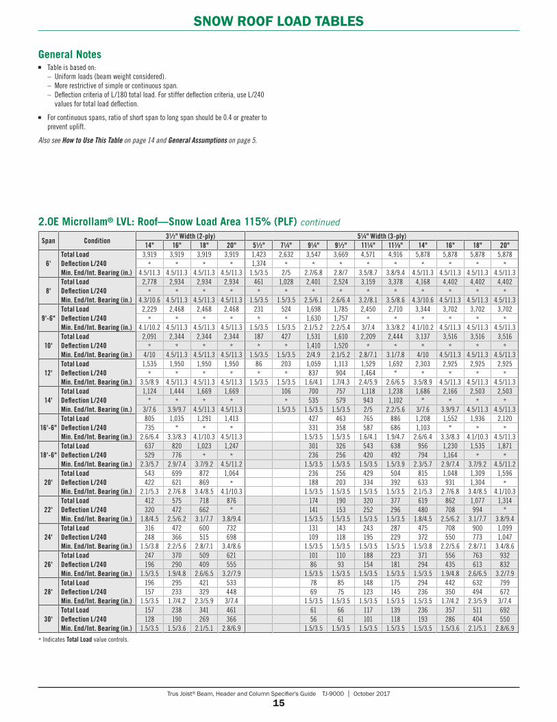
General Notes ■ Table is based on: – Uniform loads (beam weight considered). – More restrictive of simple or continuous span. – Deflection criteria of L/180 total load. For stiffer deflection criteria, use L/240
values for total load deflection.
■ For continuous spans, ratio of short span to long span should be 0.4 or greater to prevent uplift.
Also see How to Use This Table on page 14 and General Assumptions on page 5.
* Indicates Total Load value controls.
Span Condition31⁄2" Width (2-ply) 51⁄4" Width (3-ply)
14" 16" 18" 20" 51⁄2" 71⁄4" 91⁄4" 91⁄2" 111⁄4" 117⁄8" 14" 16" 18" 20"
6'Total LoadDeflection L/240Min. End/Int. Bearing (in.)
3,919 3,919 3,919 3,919 1,423 2,632 3,547 3,669 4,571 4,916 5,878 5,878 5,878 5,878* * * * 1,374 * * * * * * * * *
4.5/11.3 4.5/11.3 4.5/11.3 4.5/11.3 1.5/3.5 2/5 2.7/6.8 2.8/7 3.5/8.7 3.8/9.4 4.5/11.3 4.5/11.3 4.5/11.3 4.5/11.3
8'Total LoadDeflection L/240Min. End/Int. Bearing (in.)
2,778 2,934 2,934 2,934 461 1,028 2,401 2,524 3,159 3,378 4,168 4,402 4,402 4,402* * * * * * * * * * * * * *
4.3/10.6 4.5/11.3 4.5/11.3 4.5/11.3 1.5/3.5 1.5/3.5 2.5/6.1 2.6/6.4 3.2/8.1 3.5/8.6 4.3/10.6 4.5/11.3 4.5/11.3 4.5/11.3
9'-6"Total LoadDeflection L/240Min. End/Int. Bearing (in.)
2,229 2,468 2,468 2,468 231 524 1,698 1,785 2,450 2,710 3,344 3,702 3,702 3,702* * * * * * 1,630 1,757 * * * * * *
4.1/10.2 4.5/11.3 4.5/11.3 4.5/11.3 1.5/3.5 1.5/3.5 2.1/5.2 2.2/5.4 3/7.4 3.3/8.2 4.1/10.2 4.5/11.3 4.5/11.3 4.5/11.3
10'Total LoadDeflection L/240Min. End/Int. Bearing (in.)
2,091 2,344 2,344 2,344 187 427 1,531 1,610 2,209 2,444 3,137 3,516 3,516 3,516* * * * * * 1,410 1,520 * * * * * *
4/10 4.5/11.3 4.5/11.3 4.5/11.3 1.5/3.5 1.5/3.5 2/4.9 2.1/5.2 2.8/7.1 3.1/7.8 4/10 4.5/11.3 4.5/11.3 4.5/11.3
12'Total LoadDeflection L/240Min. End/Int. Bearing (in.)
1,535 1,950 1,950 1,950 86 203 1,059 1,113 1,529 1,692 2,303 2,925 2,925 2,925* * * * * * 837 904 1,464 * * * * *
3.5/8.9 4.5/11.3 4.5/11.3 4.5/11.3 1.5/3.5 1.5/3.5 1.6/4.1 1.7/4.3 2.4/5.9 2.6/6.5 3.5/8.9 4.5/11.3 4.5/11.3 4.5/11.3
14'Total LoadDeflection L/240Min. End/Int. Bearing (in.)
1,124 1,444 1,669 1,669 106 700 757 1,118 1,238 1,686 2,166 2,503 2,503* * * * * 535 579 943 1,102 * * * *
3/7.6 3.9/9.7 4.5/11.3 4.5/11.3 1.5/3.5 1.5/3.5 1.5/3.5 2/5 2.2/5.6 3/7.6 3.9/9.7 4.5/11.3 4.5/11.3
16'-6"Total LoadDeflection L/240Min. End/Int. Bearing (in.)
805 1,035 1,291 1,413 427 463 765 886 1,208 1,552 1,936 2,120735 * * * 331 358 587 686 1,103 * * *
2.6/6.4 3.3/8.3 4.1/10.3 4.5/11.3 1.5/3.5 1.5/3.5 1.6/4.1 1.9/4.7 2.6/6.4 3.3/8.3 4.1/10.3 4.5/11.3
18'-6"Total LoadDeflection L/240Min. End/Int. Bearing (in.)
637 820 1,023 1,247 301 326 543 638 956 1,230 1,535 1,871529 776 * * 236 256 420 492 794 1,164 * *
2.3/5.7 2.9/7.4 3.7/9.2 4.5/11.2 1.5/3.5 1.5/3.5 1.5/3.5 1.5/3.9 2.3/5.7 2.9/7.4 3.7/9.2 4.5/11.2
20'Total LoadDeflection L/240Min. End/Int. Bearing (in.)
543 699 872 1,064 236 256 429 504 815 1,048 1,309 1,596422 621 869 * 188 203 334 392 633 931 1,304 *
2.1/5.3 2.7/6.8 3.4/8.5 4.1/10.3 1.5/3.5 1.5/3.5 1.5/3.5 1.5/3.5 2.1/5.3 2.7/6.8 3.4/8.5 4.1/10.3
22'Total LoadDeflection L/240Min. End/Int. Bearing (in.)
412 575 718 876 174 190 320 377 619 862 1,077 1,314320 472 662 * 141 153 252 296 480 708 994 *
1.8/4.5 2.5/6.2 3.1/7.7 3.8/9.4 1.5/3.5 1.5/3.5 1.5/3.5 1.5/3.5 1.8/4.5 2.5/6.2 3.1/7.7 3.8/9.4
24'Total LoadDeflection L/240Min. End/Int. Bearing (in.)
316 472 600 732 131 143 243 287 475 708 900 1,099248 366 515 698 109 118 195 229 372 550 773 1,047
1.5/3.8 2.2/5.6 2.8/7.1 3.4/8.6 1.5/3.5 1.5/3.5 1.5/3.5 1.5/3.5 1.5/3.8 2.2/5.6 2.8/7.1 3.4/8.6
26'Total LoadDeflection L/240Min. End/Int. Bearing (in.)
247 370 509 621 101 110 188 223 371 556 763 932196 290 409 555 86 93 154 181 294 435 613 832
1.5/3.5 1.9/4.8 2.6/6.5 3.2/7.9 1.5/3.5 1.5/3.5 1.5/3.5 1.5/3.5 1.5/3.5 1.9/4.8 2.6/6.5 3.2/7.9
28'Total LoadDeflection L/240Min. End/Int. Bearing (in.)
196 295 421 533 78 85 148 175 294 442 632 799157 233 329 448 69 75 123 145 236 350 494 672
1.5/3.5 1.7/4.2 2.3/5.9 3/7.4 1.5/3.5 1.5/3.5 1.5/3.5 1.5/3.5 1.5/3.5 1.7/4.2 2.3/5.9 3/7.4
30'Total LoadDeflection L/240Min. End/Int. Bearing (in.)
157 238 341 461 61 66 117 139 236 357 511 692128 190 269 366 56 61 101 118 193 286 404 550
1.5/3.5 1.5/3.6 2.1/5.1 2.8/6.9 1.5/3.5 1.5/3.5 1.5/3.5 1.5/3.5 1.5/3.5 1.5/3.6 2.1/5.1 2.8/6.9
2.0E Microllam® LVL: Roof—Snow Load Area 115% (PLF) continued
Trus Joist® Beam, Header and Column Specifier's Guide TJ-9000 | October 2017
16
SNOW ROOF LOAD TABLES
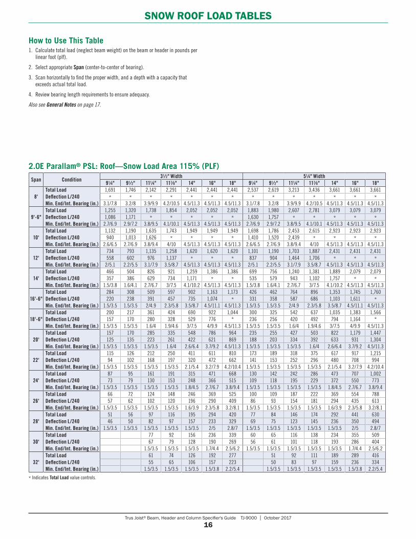
How to Use This Table 1. Calculate total load (neglect beam weight) on the beam or header in pounds per
linear foot (plf).
2. Select appropriate Span (center-to-center of bearing).
3. Scan horizontally to find the proper width, and a depth with a capacity that exceeds actual total load.
4. Review bearing length requirements to ensure adequacy.
Also see General Notes on page 17.
* Indicates Total Load value controls.
Span Condition31⁄2" Width 51⁄4" Width
91⁄4" 91⁄2" 111⁄4" 117⁄8" 14" 16" 18" 91⁄4" 91⁄2" 111⁄4" 117⁄8" 14" 16" 18"
8'Total LoadDeflection L/240Min. End/Int. Bearing (in.)
1,691 1,746 2,142 2,291 2,441 2,441 2,441 2,537 2,619 3,213 3,436 3,661 3,661 3,661* * * * * * * * * * * * * *
3.1/7.8 3.2/8 3.9/9.9 4.2/10.5 4.5/11.3 4.5/11.3 4.5/11.3 3.1/7.8 3.2/8 3.9/9.9 4.2/10.5 4.5/11.3 4.5/11.3 4.5/11.3
9'-6"Total LoadDeflection L/240Min. End/Int. Bearing (in.)
1,255 1,320 1,738 1,854 2,052 2,052 2,052 1,883 1,980 2,607 2,781 3,079 3,079 3,0791,086 1,171 * * * * * 1,630 1,757 * * * * *
2.7/6.9 2.9/7.2 3.8/9.5 4.1/10.1 4.5/11.3 4.5/11.3 4.5/11.3 2.7/6.9 2.9/7.2 3.8/9.5 4.1/10.1 4.5/11.3 4.5/11.3 4.5/11.3
10'Total LoadDeflection L/240Min. End/Int. Bearing (in.)
1,132 1,190 1,635 1,743 1,949 1,949 1,949 1,698 1,786 2,453 2,615 2,923 2,923 2,923940 1,013 1,626 * * * * 1,410 1,520 2,439 * * * *
2.6/6.5 2.7/6.9 3.8/9.4 4/10 4.5/11.3 4.5/11.3 4.5/11.3 2.6/6.5 2.7/6.9 3.8/9.4 4/10 4.5/11.3 4.5/11.3 4.5/11.3
12'Total LoadDeflection L/240Min. End/Int. Bearing (in.)
734 793 1,135 1,258 1,620 1,620 1,620 1,101 1,190 1,703 1,887 2,431 2,431 2,431558 602 976 1,137 * * * 837 904 1,464 1,706 * * *
2/5.1 2.2/5.5 3.1/7.9 3.5/8.7 4.5/11.3 4.5/11.3 4.5/11.3 2/5.1 2.2/5.5 3.1/7.9 3.5/8.7 4.5/11.3 4.5/11.3 4.5/11.3
14'Total LoadDeflection L/240Min. End/Int. Bearing (in.)
466 504 826 921 1,259 1,386 1,386 699 756 1,240 1,381 1,889 2,079 2,079357 386 629 734 1,171 * * 535 579 943 1,102 1,757 * *
1.5/3.8 1.6/4.1 2.7/6.7 3/7.5 4.1/10.2 4.5/11.3 4.5/11.3 1.5/3.8 1.6/4.1 2.7/6.7 3/7.5 4.1/10.2 4.5/11.3 4.5/11.3
16'-6"Total LoadDeflection L/240Min. End/Int. Bearing (in.)
284 308 509 597 902 1,163 1,173 426 462 764 896 1,353 1,745 1,760220 238 391 457 735 1,074 * 331 358 587 686 1,103 1,611 *
1.5/3.5 1.5/3.5 2/4.9 2.3/5.8 3.5/8.7 4.5/11.1 4.5/11.3 1.5/3.5 1.5/3.5 2/4.9 2.3/5.8 3.5/8.7 4.5/11.1 4.5/11.3
18'-6"Total LoadDeflection L/240Min. End/Int. Bearing (in.)
200 217 361 424 690 922 1,044 300 325 542 637 1,035 1,383 1,566157 170 280 328 529 776 * 236 256 420 492 794 1,164 *
1.5/3.5 1.5/3.5 1.6/4 1.9/4.6 3/7.5 4/9.9 4.5/11.3 1.5/3.5 1.5/3.5 1.6/4 1.9/4.6 3/7.5 4/9.9 4.5/11.3
20'Total LoadDeflection L/240Min. End/Int. Bearing (in.)
157 170 285 335 548 786 964 235 255 427 503 822 1,179 1,447125 135 223 261 422 621 869 188 203 334 392 633 931 1,304
1.5/3.5 1.5/3.5 1.5/3.5 1.6/4 2.6/6.4 3.7/9.2 4.5/11.3 1.5/3.5 1.5/3.5 1.5/3.5 1.6/4 2.6/6.4 3.7/9.2 4.5/11.3
22'Total LoadDeflection L/240Min. End/Int. Bearing (in.)
115 126 212 250 411 611 810 173 189 318 375 617 917 1,21594 102 168 197 320 472 662 141 153 252 296 480 708 994
1.5/3.5 1.5/3.5 1.5/3.5 1.5/3.5 2.1/5.4 3.2/7.9 4.2/10.4 1.5/3.5 1.5/3.5 1.5/3.5 1.5/3.5 2.1/5.4 3.2/7.9 4.2/10.4
24'Total LoadDeflection L/240Min. End/Int. Bearing (in.)
87 95 161 191 315 471 668 130 142 242 286 473 707 1,00273 79 130 153 248 366 515 109 118 195 229 372 550 773
1.5/3.5 1.5/3.5 1.5/3.5 1.5/3.5 1.8/4.5 2.7/6.7 3.8/9.4 1.5/3.5 1.5/3.5 1.5/3.5 1.5/3.5 1.8/4.5 2.7/6.7 3.8/9.4
26'Total LoadDeflection L/240Min. End/Int. Bearing (in.)
66 72 124 148 246 369 525 100 109 187 222 369 554 78857 62 102 120 196 290 409 86 93 154 181 294 435 613
1.5/3.5 1.5/3.5 1.5/3.5 1.5/3.5 1.6/3.9 2.3/5.8 3.2/8.1 1.5/3.5 1.5/3.5 1.5/3.5 1.5/3.5 1.6/3.9 2.3/5.8 3.2/8.1
28'Total LoadDeflection L/240Min. End/Int. Bearing (in.)
51 56 97 116 195 294 420 77 84 146 174 292 441 63046 50 82 97 157 233 329 69 75 123 145 236 350 494
1.5/3.5 1.5/3.5 1.5/3.5 1.5/3.5 1.5/3.5 2/5 2.8/7 1.5/3.5 1.5/3.5 1.5/3.5 1.5/3.5 1.5/3.5 2/5 2.8/7
30'Total LoadDeflection L/240Min. End/Int. Bearing (in.)
77 92 156 236 339 60 65 116 138 234 355 50967 79 128 190 269 56 61 101 118 193 286 404
1.5/3.5 1.5/3.5 1.5/3.5 1.7/4.4 2.5/6.2 1.5/3.5 1.5/3.5 1.5/3.5 1.5/3.5 1.5/3.5 1.7/4.4 2.5/6.2
32'Total LoadDeflection L/240Min. End/Int. Bearing (in.)
61 74 126 192 277 51 92 111 189 289 41655 65 106 157 223 50 83 97 159 236 334
1.5/3.5 1.5/3.5 1.5/3.5 1.5/3.8 2.2/5.4 1.5/3.5 1.5/3.5 1.5/3.5 1.5/3.5 1.5/3.8 2.2/5.4
2.0E Parallam® PSL: Roof—Snow Load Area 115% (PLF)
Trus Joist® Beam, Header and Column Specifier's Guide TJ-9000 | October 2017
17
SNOW ROOF LOAD TABLES
* Indicates Total Load value controls.
Span Condition7" Width
91⁄4" 91⁄2" 111⁄4" 117⁄8" 14" 16" 18"
8'Total LoadDeflection L/240Min. End/Int. Bearing (in.)
3,383 3,492 4,285 4,582 4,882 4,882 4,882* * * * * * *
3.1/7.8 3.2/8 3.9/9.9 4.2/10.5 4.5/11.3 4.5/11.3 4.5/11.3
9'-6"Total LoadDeflection L/240Min. End/Int. Bearing (in.)
2,511 2,641 3,477 3,709 4,105 4,105 4,1052,173 2,342 * * * * *
2.7/6.9 2.9/7.2 3.8/9.5 4.1/10.1 4.5/11.3 4.5/11.3 4.5/11.3
10'Total LoadDeflection L/240Min. End/Int. Bearing (in.)
2,264 2,381 3,271 3,487 3,898 3,898 3,8981,880 2,027 3,252 * * * *
2.6/6.5 2.7/6.9 3.8/9.4 4/10 4.5/11.3 4.5/11.3 4.5/11.3
12'Total LoadDeflection L/240Min. End/Int. Bearing (in.)
1,468 1,586 2,271 2,517 3,241 3,241 3,2411,116 1,205 1,953 2,274 * * *2/5.1 2.2/5.5 3.1/7.9 3.5/8.7 4.5/11.3 4.5/11.3 4.5/11.3
14'Total LoadDeflection L/240Min. End/Int. Bearing (in.)
932 1,008 1,653 1,842 2,519 2,773 2,773714 772 1,258 1,469 2,342 * *
1.5/3.8 1.6/4.1 2.7/6.7 3/7.5 4.1/10.2 4.5/11.3 4.5/11.3
16'-6"Total LoadDeflection L/240Min. End/Int. Bearing (in.)
569 616 1,019 1,195 1,805 2,327 2,346441 477 782 915 1,470 2,148 *
1.5/3.5 1.5/3.5 2/4.9 2.3/5.8 3.5/8.7 4.5/11.1 4.5/11.3
18'-6"Total LoadDeflection L/240Min. End/Int. Bearing (in.)
400 434 723 849 1,381 1,844 2,089315 341 560 656 1,058 1,553 *
1.5/3.5 1.5/3.5 1.6/4 1.9/4.6 3/7.5 4/9.9 4.5/11.3
20'Total LoadDeflection L/240Min. End/Int. Bearing (in.)
314 340 570 671 1,096 1,572 1,929250 271 446 523 845 1,242 1,739
1.5/3.5 1.5/3.5 1.5/3.5 1.6/4 2.6/6.4 3.7/9.2 4.5/11.3
22'Total LoadDeflection L/240Min. End/Int. Bearing (in.)
231 252 425 501 823 1,223 1,620189 204 337 395 640 944 1,325
1.5/3.5 1.5/3.5 1.5/3.5 1.5/3.5 2.1/5.4 3.2/7.9 4.2/10.4
24'Total LoadDeflection L/240Min. End/Int. Bearing (in.)
174 190 323 382 631 942 1,336146 158 260 306 496 733 1,031
1.5/3.5 1.5/3.5 1.5/3.5 1.5/3.5 1.8/4.5 2.7/6.7 3.8/9.4
26'Total LoadDeflection L/240Min. End/Int. Bearing (in.)
133 145 249 296 492 739 1,051115 124 205 241 392 580 818
1.5/3.5 1.5/3.5 1.5/3.5 1.5/3.5 1.6/3.9 2.3/5.8 3.2/8.1
28'Total LoadDeflection L/240Min. End/Int. Bearing (in.)
102 112 195 232 390 588 84092 100 165 194 315 467 659
1.5/3.5 1.5/3.5 1.5/3.5 1.5/3.5 1.5/3.5 2/5 2.8/7
30'Total LoadDeflection L/240Min. End/Int. Bearing (in.)
80 87 154 184 312 473 67975 81 134 158 257 381 539
1.5/3.5 1.5/3.5 1.5/3.5 1.5/3.5 1.5/3.5 1.7/4.4 2.5/6.2
32'Total LoadDeflection L/240Min. End/Int. Bearing (in.)
62 68 123 148 253 385 55562 67 111 130 212 315 446
1.5/3.5 1.5/3.5 1.5/3.5 1.5/3.5 1.5/3.5 1.5/3.8 2.2/5.4
2.0E Parallam® PSL: Roof—Snow Load Area 115% (PLF) continued
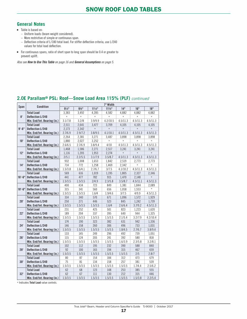
General Notes■ Table is based on: – Uniform loads (beam weight considered). – More restrictive of simple or continuous span. – Deflection criteria of L/180 total load. For stiffer deflection criteria, use L/240
values for total load deflection.
■ For continuous spans, ratio of short span to long span should be 0.4 or greater to prevent uplift.
Also see How to Use This Table on page 16 and General Assumptions on page 5.
Trus Joist® Beam, Header and Column Specifier's Guide TJ-9000 | October 2017
18
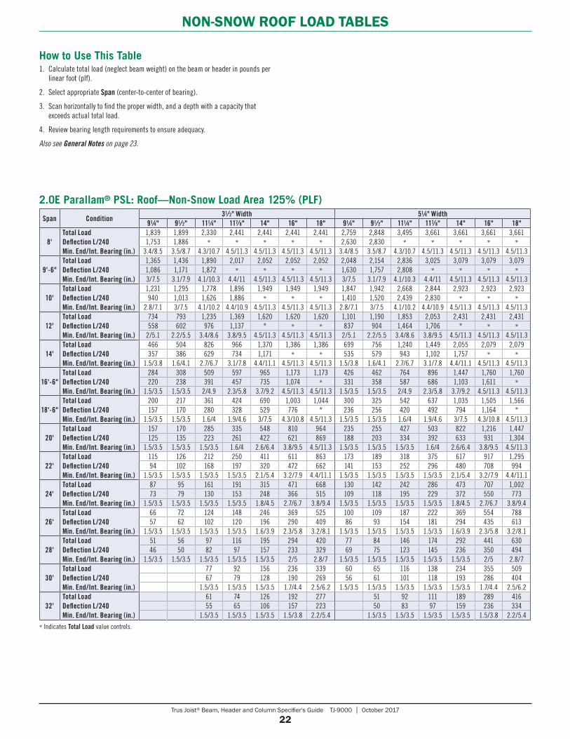
NON-SNOW ROOF LOAD TABLES
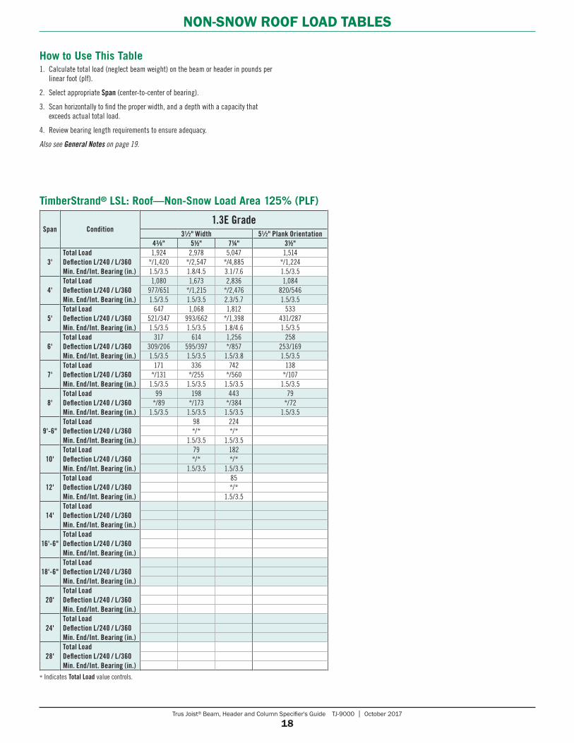
How to Use This Table1. Calculate total load (neglect beam weight) on the beam or header in pounds per
linear foot (plf).
2. Select appropriate Span (center-to-center of bearing).
3. Scan horizontally to find the proper width, and a depth with a capacity that exceeds actual total load.
4. Review bearing length requirements to ensure adequacy.
Also see General Notes on page 19.
* Indicates Total Load value controls.
Span Condition1.3E Grade
31⁄2" Width 51⁄2" Plank Orientation43⁄8" 51⁄2" 71⁄4" 31⁄2"
3'Total LoadDeflection L/240 / L/360Min. End/Int. Bearing (in.)
1,924 2,978 5,047 1,514*/1,420 */2,547 */4,885 */1,2241.5/3.5 1.8/4.5 3.1/7.6 1.5/3.5
4'Total LoadDeflection L/240 / L/360Min. End/Int. Bearing (in.)
1,080 1,673 2,836 1,084977/651 */1,215 */2,476 820/5461.5/3.5 1.5/3.5 2.3/5.7 1.5/3.5
5'Total LoadDeflection L/240 / L/360Min. End/Int. Bearing (in.)
647 1,068 1,812 533521/347 993/662 */1,398 431/2871.5/3.5 1.5/3.5 1.8/4.6 1.5/3.5
6'Total LoadDeflection L/240 / L/360Min. End/Int. Bearing (in.)
317 614 1,256 258309/206 595/397 */857 253/1691.5/3.5 1.5/3.5 1.5/3.8 1.5/3.5
7'Total LoadDeflection L/240 / L/360Min. End/Int. Bearing (in.)
171 336 742 138*/131 */255 */560 */107
1.5/3.5 1.5/3.5 1.5/3.5 1.5/3.5
8'Total LoadDeflection L/240 / L/360Min. End/Int. Bearing (in.)
99 198 443 79*/89 */173 */384 */72
1.5/3.5 1.5/3.5 1.5/3.5 1.5/3.5
9'-6"Total LoadDeflection L/240 / L/360Min. End/Int. Bearing (in.)
98 224*/* */*
1.5/3.5 1.5/3.5
10'Total LoadDeflection L/240 / L/360Min. End/Int. Bearing (in.)
79 182*/* */*
1.5/3.5 1.5/3.5
12'Total LoadDeflection L/240 / L/360Min. End/Int. Bearing (in.)
85*/*
1.5/3.5
14'Total LoadDeflection L/240 / L/360Min. End/Int. Bearing (in.)
16'-6"Total LoadDeflection L/240 / L/360Min. End/Int. Bearing (in.)
18'-6"Total LoadDeflection L/240 / L/360Min. End/Int. Bearing (in.)
20'Total LoadDeflection L/240 / L/360Min. End/Int. Bearing (in.)
24'Total LoadDeflection L/240 / L/360Min. End/Int. Bearing (in.)
28'Total LoadDeflection L/240 / L/360 Min. End/Int. Bearing (in.)
TimberStrand® LSL: Roof—Non-Snow Load Area 125% (PLF)
Trus Joist® Beam, Header and Column Specifier's Guide TJ-9000 | October 2017
19
NON-SNOW ROOF LOAD TABLES
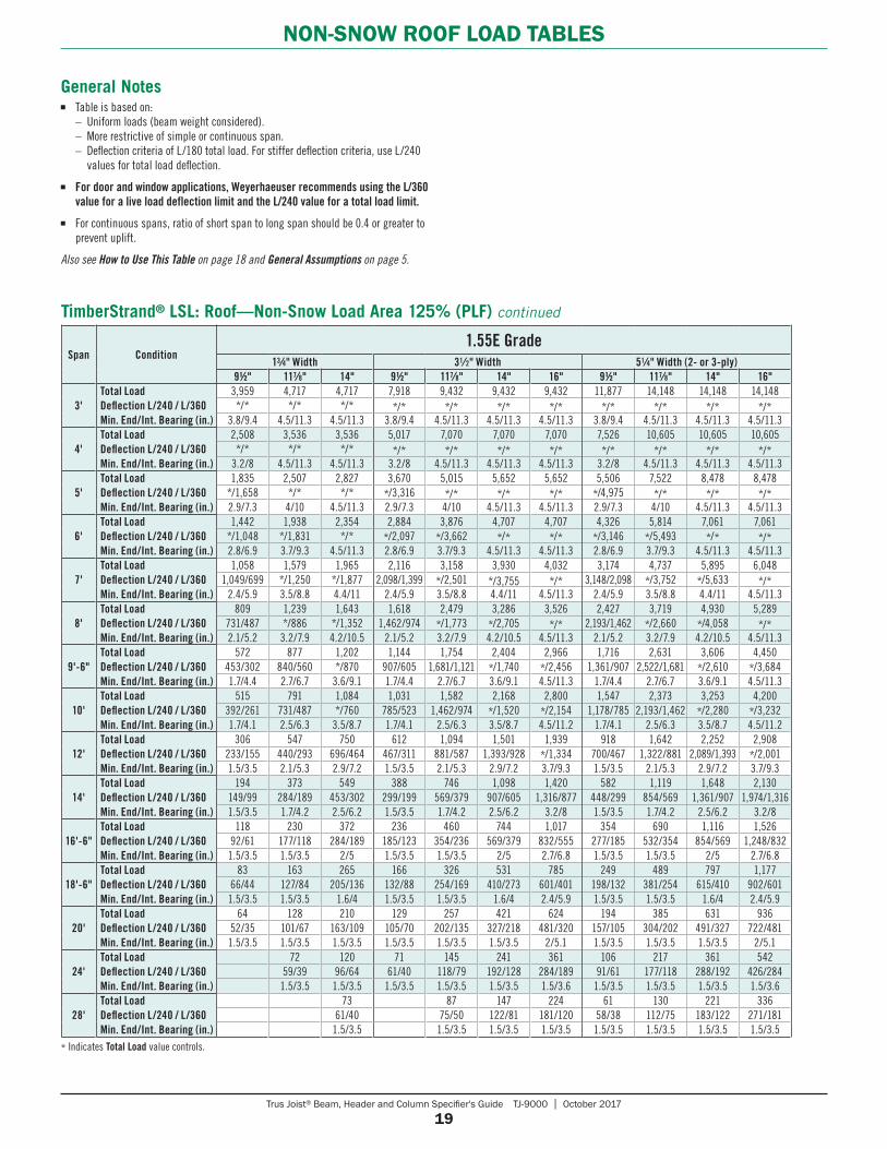
General Notes ■ Table is based on: – Uniform loads (beam weight considered). – More restrictive of simple or continuous span. – Deflection criteria of L/180 total load. For stiffer deflection criteria, use L/240
values for total load deflection.
■ For door and window applications, Weyerhaeuser recommends using the L/360 value for a live load deflection limit and the L/240 value for a total load limit.
■ For continuous spans, ratio of short span to long span should be 0.4 or greater to prevent uplift.
Also see How to Use This Table on page 18 and General Assumptions on page 5.
* Indicates Total Load value controls.
Span Condition1.55E Grade
13⁄4" Width 31⁄2" Width 51⁄4" Width (2- or 3-ply)91⁄2" 117⁄8" 14" 91⁄2" 117⁄8" 14" 16" 91⁄2" 117⁄8" 14" 16"
3'Total LoadDeflection L/240 / L/360Min. End/Int. Bearing (in.)
3,959 4,717 4,717 7,918 9,432 9,432 9,432 11,877 14,148 14,148 14,148*/* */* */* */* */* */* */* */* */* */* */*
3.8/9.4 4.5/11.3 4.5/11.3 3.8/9.4 4.5/11.3 4.5/11.3 4.5/11.3 3.8/9.4 4.5/11.3 4.5/11.3 4.5/11.3
4'Total LoadDeflection L/240 / L/360Min. End/Int. Bearing (in.)
2,508 3,536 3,536 5,017 7,070 7,070 7,070 7,526 10,605 10,605 10,605*/* */* */* */* */* */* */* */* */* */* */*
3.2/8 4.5/11.3 4.5/11.3 3.2/8 4.5/11.3 4.5/11.3 4.5/11.3 3.2/8 4.5/11.3 4.5/11.3 4.5/11.3
5'Total LoadDeflection L/240 / L/360Min. End/Int. Bearing (in.)
1,835 2,507 2,827 3,670 5,015 5,652 5,652 5,506 7,522 8,478 8,478*/1,658 */* */* */3,316 */* */* */* */4,975 */* */* */*2.9/7.3 4/10 4.5/11.3 2.9/7.3 4/10 4.5/11.3 4.5/11.3 2.9/7.3 4/10 4.5/11.3 4.5/11.3
6'Total LoadDeflection L/240 / L/360Min. End/Int. Bearing (in.)
1,442 1,938 2,354 2,884 3,876 4,707 4,707 4,326 5,814 7,061 7,061*/1,048 */1,831 */* */2,097 */3,662 */* */* */3,146 */5,493 */* */*2.8/6.9 3.7/9.3 4.5/11.3 2.8/6.9 3.7/9.3 4.5/11.3 4.5/11.3 2.8/6.9 3.7/9.3 4.5/11.3 4.5/11.3
7'Total LoadDeflection L/240 / L/360Min. End/Int. Bearing (in.)
1,058 1,579 1,965 2,116 3,158 3,930 4,032 3,174 4,737 5,895 6,0481,049/699 */1,250 */1,877 2,098/1,399 */2,501 */3,755 */* 3,148/2,098 */3,752 */5,633 */*
2.4/5.9 3.5/8.8 4.4/11 2.4/5.9 3.5/8.8 4.4/11 4.5/11.3 2.4/5.9 3.5/8.8 4.4/11 4.5/11.3
8'Total LoadDeflection L/240 / L/360Min. End/Int. Bearing (in.)
809 1,239 1,643 1,618 2,479 3,286 3,526 2,427 3,719 4,930 5,289731/487 */886 */1,352 1,462/974 */1,773 */2,705 */* 2,193/1,462 */2,660 */4,058 */*2.1/5.2 3.2/7.9 4.2/10.5 2.1/5.2 3.2/7.9 4.2/10.5 4.5/11.3 2.1/5.2 3.2/7.9 4.2/10.5 4.5/11.3
9'-6"Total LoadDeflection L/240 / L/360Min. End/Int. Bearing (in.)
572 877 1,202 1,144 1,754 2,404 2,966 1,716 2,631 3,606 4,450453/302 840/560 */870 907/605 1,681/1,121 */1,740 */2,456 1,361/907 2,522/1,681 */2,610 */3,6841.7/4.4 2.7/6.7 3.6/9.1 1.7/4.4 2.7/6.7 3.6/9.1 4.5/11.3 1.7/4.4 2.7/6.7 3.6/9.1 4.5/11.3
10'Total LoadDeflection L/240 / L/360Min. End/Int. Bearing (in.)
515 791 1,084 1,031 1,582 2,168 2,800 1,547 2,373 3,253 4,200392/261 731/487 */760 785/523 1,462/974 */1,520 */2,154 1,178/785 2,193/1,462 */2,280 */3,2321.7/4.1 2.5/6.3 3.5/8.7 1.7/4.1 2.5/6.3 3.5/8.7 4.5/11.2 1.7/4.1 2.5/6.3 3.5/8.7 4.5/11.2
12'Total LoadDeflection L/240 / L/360Min. End/Int. Bearing (in.)
306 547 750 612 1,094 1,501 1,939 918 1,642 2,252 2,908233/155 440/293 696/464 467/311 881/587 1,393/928 */1,334 700/467 1,322/881 2,089/1,393 */2,0011.5/3.5 2.1/5.3 2.9/7.2 1.5/3.5 2.1/5.3 2.9/7.2 3.7/9.3 1.5/3.5 2.1/5.3 2.9/7.2 3.7/9.3
14'Total LoadDeflection L/240 / L/360Min. End/Int. Bearing (in.)
194 373 549 388 746 1,098 1,420 582 1,119 1,648 2,130149/99 284/189 453/302 299/199 569/379 907/605 1,316/877 448/299 854/569 1,361/907 1,974/1,3161.5/3.5 1.7/4.2 2.5/6.2 1.5/3.5 1.7/4.2 2.5/6.2 3.2/8 1.5/3.5 1.7/4.2 2.5/6.2 3.2/8
16'-6"Total LoadDeflection L/240 / L/360Min. End/Int. Bearing (in.)
118 230 372 236 460 744 1,017 354 690 1,116 1,52692/61 177/118 284/189 185/123 354/236 569/379 832/555 277/185 532/354 854/569 1,248/832
1.5/3.5 1.5/3.5 2/5 1.5/3.5 1.5/3.5 2/5 2.7/6.8 1.5/3.5 1.5/3.5 2/5 2.7/6.8
18'-6"Total LoadDeflection L/240 / L/360Min. End/Int. Bearing (in.)
83 163 265 166 326 531 785 249 489 797 1,17766/44 127/84 205/136 132/88 254/169 410/273 601/401 198/132 381/254 615/410 902/601
1.5/3.5 1.5/3.5 1.6/4 1.5/3.5 1.5/3.5 1.6/4 2.4/5.9 1.5/3.5 1.5/3.5 1.6/4 2.4/5.9
20'Total LoadDeflection L/240 / L/360Min. End/Int. Bearing (in.)
64 128 210 129 257 421 624 194 385 631 93652/35 101/67 163/109 105/70 202/135 327/218 481/320 157/105 304/202 491/327 722/4811.5/3.5 1.5/3.5 1.5/3.5 1.5/3.5 1.5/3.5 1.5/3.5 2/5.1 1.5/3.5 1.5/3.5 1.5/3.5 2/5.1
24'Total LoadDeflection L/240 / L/360Min. End/Int. Bearing (in.)
72 120 71 145 241 361 106 217 361 54259/39 96/64 61/40 118/79 192/128 284/189 91/61 177/118 288/192 426/284
1.5/3.5 1.5/3.5 1.5/3.5 1.5/3.5 1.5/3.5 1.5/3.6 1.5/3.5 1.5/3.5 1.5/3.5 1.5/3.6
28'Total LoadDeflection L/240 / L/360 Min. End/Int. Bearing (in.)
73 87 147 224 61 130 221 33661/40 75/50 122/81 181/120 58/38 112/75 183/122 271/181
1.5/3.5 1.5/3.5 1.5/3.5 1.5/3.5 1.5/3.5 1.5/3.5 1.5/3.5 1.5/3.5
TimberStrand® LSL: Roof—Non-Snow Load Area 125% (PLF) continued
Trus Joist® Beam, Header and Column Specifier's Guide TJ-9000 | October 2017
20
NON-SNOW ROOF LOAD TABLES
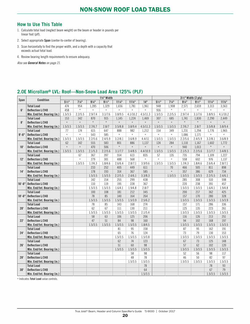
How to Use This Table1. Calculate total load (neglect beam weight) on the beam or header in pounds per
linear foot (plf).
2. Select appropriate Span (center-to-center of bearing).
3. Scan horizontally to find the proper width, and a depth with a capacity that exceeds actual total load.
4. Review bearing length requirements to ensure adequacy.
Also see General Notes on page 21.
* Indicates Total Load value controls.
Span Condition13⁄4" Width 31⁄2" Width (2 ply)
51⁄2" 71⁄4" 91⁄4" 91⁄2" 111⁄4" 117⁄8" 14" 51⁄2" 71⁄4" 91⁄4" 91⁄2" 111⁄4" 117⁄8"
6'Total LoadDeflection L/240Min. End/Int. Bearing (in.)
474 954 1,285 1,329 1,656 1,781 1,961 948 1,908 2,571 2,659 3,313 3,563458 * * * * * * 916 * * * * *
1.5/3.5 2.2/5.5 2.9/7.4 3.1/7.6 3.8/9.5 4.1/10.2 4.5/11.3 1.5/3.5 2.2/5.5 2.9/7.4 3.1/7.6 3.8/9.5 4.1/10.2
8'Total LoadDeflection L/240Min. End/Int. Bearing (in.)
153 342 870 915 1,145 1,224 1,469 307 685 1,741 1,830 2,290 2,449* * * * * * * * * * * * *
1.5/3.5 1.5/3.5 2.7/6.7 2.8/7 3.5/8.8 3.8/9.4 4.5/11.3 1.5/3.5 1.5/3.5 2.7/6.7 2.8/7 3.5/8.8 3.8/9.4
9'-6"Total LoadDeflection L/240Min. End/Int. Bearing (in.)
77 174 615 647 888 982 1,212 154 349 1,231 1,294 1,776 1,965* * 543 585 * * * * * 1,086 1,171 * *
1.5/3.5 1.5/3.5 2.2/5.6 2.4/5.9 3.2/8.1 3.6/8.9 4.4/11 1.5/3.5 1.5/3.5 2.2/5.6 2.4/5.9 3.2/8.1 3.6/8.9
10'Total LoadDeflection L/240Min. End/Int. Bearing (in.)
62 142 555 583 801 886 1,137 124 284 1,110 1,167 1,602 1,772* * 470 506 * * * * * 940 1,013 * *
1.5/3.5 1.5/3.5 2.1/5.3 2.2/5.6 3.1/7.7 3.4/8.5 4.4/10.9 1.5/3.5 1.5/3.5 2.1/5.3 2.2/5.6 3.1/7.7 3.4/8.5
12'Total LoadDeflection L/240Min. End/Int. Bearing (in.)
67 367 397 554 613 835 57 135 735 794 1,109 1,227* 279 301 488 568 * * * 558 602 976 1,137
1.5/3.5 1.7/4.3 1.8/4.6 2.6/6.4 2.8/7.1 3.9/9.6 1.5/3.5 1.5/3.5 1.7/4.3 1.8/4.6 2.6/6.4 2.8/7.1
14'Total LoadDeflection L/240Min. End/Int. Bearing (in.)
233 252 405 449 611 70 466 505 811 898178 193 314 367 585 * 357 386 629 734
1.5/3.5 1.5/3.5 2.2/5.5 2.4/6.1 3.3/8.3 1.5/3.5 1.5/3.5 1.5/3.5 2.2/5.5 2.4/6.1
16'-6"Total LoadDeflection L/240Min. End/Int. Bearing (in.)
142 154 255 299 438 285 308 510 598110 119 195 228 367 220 238 391 457
1.5/3.5 1.5/3.5 1.6/4.1 1.9/4.8 2.8/7 1.5/3.5 1.5/3.5 1.6/4.1 1.9/4.8
18'-6"Total LoadDeflection L/240Min. End/Int. Bearing (in.)
100 108 181 212 345 200 217 362 42578 85 140 164 264 157 170 280 328
1.5/3.5 1.5/3.5 1.5/3.5 1.5/3.9 2.5/6.2 1.5/3.5 1.5/3.5 1.5/3.5 1.5/3.9
20'Total LoadDeflection L/240Min. End/Int. Bearing (in.)
78 85 143 168 274 157 171 286 33662 67 111 130 211 125 135 223 261
1.5/3.5 1.5/3.5 1.5/3.5 1.5/3.5 2.1/5.4 1.5/3.5 1.5/3.5 1.5/3.5 1.5/3.5
22'Total LoadDeflection L/240Min. End/Int. Bearing (in.)
58 63 106 125 206 116 126 213 25147 51 84 98 160 94 102 168 197
1.5/3.5 1.5/3.5 1.5/3.5 1.5/3.5 1.8/4.5 1.5/3.5 1.5/3.5 1.5/3.5 1.5/3.5
24'Total LoadDeflection L/240Min. End/Int. Bearing (in.)
81 95 158 87 95 162 19165 76 124 73 79 130 153
1.5/3.5 1.5/3.5 1.5/3.8 1.5/3.5 1.5/3.5 1.5/3.5 1.5/3.5
26'Total LoadDeflection L/240Min. End/Int. Bearing (in.)
62 74 123 67 73 125 14851 60 98 57 62 102 120
1.5/3.5 1.5/3.5 1.5/3.5 1.5/3.5 1.5/3.5 1.5/3.5 1.5/3.5
28'Total LoadDeflection L/240Min. End/Int. Bearing (in.)
58 98 52 56 98 11748 78 46 50 82 97
1.5/3.5 1.5/3.5 1.5/3.5 1.5/3.5 1.5/3.5 1.5/3.5
30'Total LoadDeflection L/240Min. End/Int. Bearing (in.)
78 78 9364 67 79
1.5/3.5 1.5/3.5 1.5/3.5
2.0E Microllam® LVL: Roof—Non-Snow Load Area 125% (PLF)
Trus Joist® Beam, Header and Column Specifier's Guide TJ-9000 | October 2017
21
NON-SNOW ROOF LOAD TABLES
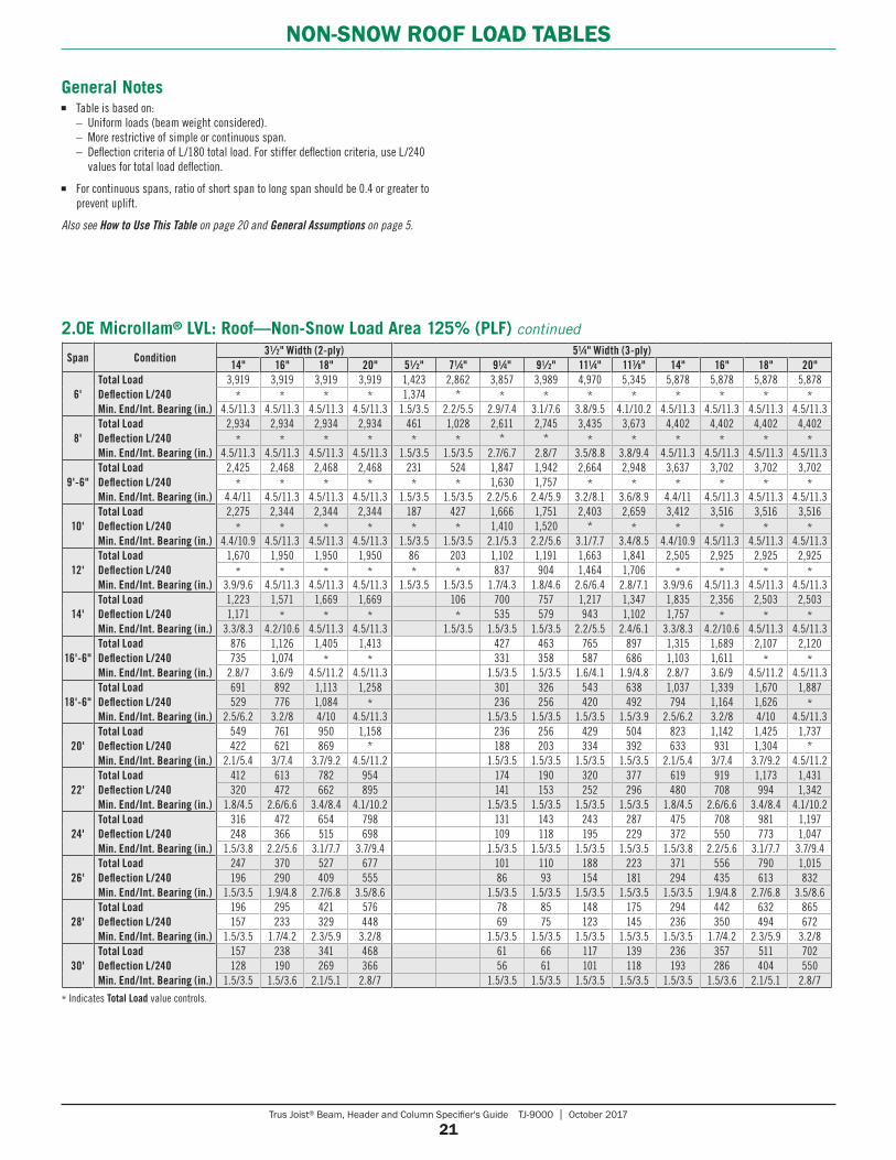
* Indicates Total Load value controls.
Span Condition31⁄2" Width (2-ply) 51⁄4" Width (3-ply)
14" 16" 18" 20" 51⁄2" 71⁄4" 91⁄4" 91⁄2" 111⁄4" 117⁄8" 14" 16" 18" 20"
6'Total LoadDeflection L/240Min. End/Int. Bearing (in.)
3,919 3,919 3,919 3,919 1,423 2,862 3,857 3,989 4,970 5,345 5,878 5,878 5,878 5,878* * * * 1,374 * * * * * * * * *
4.5/11.3 4.5/11.3 4.5/11.3 4.5/11.3 1.5/3.5 2.2/5.5 2.9/7.4 3.1/7.6 3.8/9.5 4.1/10.2 4.5/11.3 4.5/11.3 4.5/11.3 4.5/11.3
8'Total LoadDeflection L/240Min. End/Int. Bearing (in.)
2,934 2,934 2,934 2,934 461 1,028 2,611 2,745 3,435 3,673 4,402 4,402 4,402 4,402* * * * * * * * * * * * * *
4.5/11.3 4.5/11.3 4.5/11.3 4.5/11.3 1.5/3.5 1.5/3.5 2.7/6.7 2.8/7 3.5/8.8 3.8/9.4 4.5/11.3 4.5/11.3 4.5/11.3 4.5/11.3
9'-6"Total LoadDeflection L/240Min. End/Int. Bearing (in.)
2,425 2,468 2,468 2,468 231 524 1,847 1,942 2,664 2,948 3,637 3,702 3,702 3,702* * * * * * 1,630 1,757 * * * * * *
4.4/11 4.5/11.3 4.5/11.3 4.5/11.3 1.5/3.5 1.5/3.5 2.2/5.6 2.4/5.9 3.2/8.1 3.6/8.9 4.4/11 4.5/11.3 4.5/11.3 4.5/11.3
10'Total LoadDeflection L/240Min. End/Int. Bearing (in.)
2,275 2,344 2,344 2,344 187 427 1,666 1,751 2,403 2,659 3,412 3,516 3,516 3,516* * * * * * 1,410 1,520 * * * * * *
4.4/10.9 4.5/11.3 4.5/11.3 4.5/11.3 1.5/3.5 1.5/3.5 2.1/5.3 2.2/5.6 3.1/7.7 3.4/8.5 4.4/10.9 4.5/11.3 4.5/11.3 4.5/11.3
12'Total LoadDeflection L/240Min. End/Int. Bearing (in.)
1,670 1,950 1,950 1,950 86 203 1,102 1,191 1,663 1,841 2,505 2,925 2,925 2,925* * * * * * 837 904 1,464 1,706 * * * *
3.9/9.6 4.5/11.3 4.5/11.3 4.5/11.3 1.5/3.5 1.5/3.5 1.7/4.3 1.8/4.6 2.6/6.4 2.8/7.1 3.9/9.6 4.5/11.3 4.5/11.3 4.5/11.3
14'Total LoadDeflection L/240Min. End/Int. Bearing (in.)
1,223 1,571 1,669 1,669 106 700 757 1,217 1,347 1,835 2,356 2,503 2,5031,171 * * * * 535 579 943 1,102 1,757 * * *
3.3/8.3 4.2/10.6 4.5/11.3 4.5/11.3 1.5/3.5 1.5/3.5 1.5/3.5 2.2/5.5 2.4/6.1 3.3/8.3 4.2/10.6 4.5/11.3 4.5/11.3
16'-6"Total LoadDeflection L/240Min. End/Int. Bearing (in.)
876 1,126 1,405 1,413 427 463 765 897 1,315 1,689 2,107 2,120735 1,074 * * 331 358 587 686 1,103 1,611 * *
2.8/7 3.6/9 4.5/11.2 4.5/11.3 1.5/3.5 1.5/3.5 1.6/4.1 1.9/4.8 2.8/7 3.6/9 4.5/11.2 4.5/11.3
18'-6"Total LoadDeflection L/240Min. End/Int. Bearing (in.)
691 892 1,113 1,258 301 326 543 638 1,037 1,339 1,670 1,887529 776 1,084 * 236 256 420 492 794 1,164 1,626 *
2.5/6.2 3.2/8 4/10 4.5/11.3 1.5/3.5 1.5/3.5 1.5/3.5 1.5/3.9 2.5/6.2 3.2/8 4/10 4.5/11.3
20'Total LoadDeflection L/240Min. End/Int. Bearing (in.)
549 761 950 1,158 236 256 429 504 823 1,142 1,425 1,737422 621 869 * 188 203 334 392 633 931 1,304 *
2.1/5.4 3/7.4 3.7/9.2 4.5/11.2 1.5/3.5 1.5/3.5 1.5/3.5 1.5/3.5 2.1/5.4 3/7.4 3.7/9.2 4.5/11.2
22'Total LoadDeflection L/240Min. End/Int. Bearing (in.)
412 613 782 954 174 190 320 377 619 919 1,173 1,431320 472 662 895 141 153 252 296 480 708 994 1,342
1.8/4.5 2.6/6.6 3.4/8.4 4.1/10.2 1.5/3.5 1.5/3.5 1.5/3.5 1.5/3.5 1.8/4.5 2.6/6.6 3.4/8.4 4.1/10.2
24'Total LoadDeflection L/240Min. End/Int. Bearing (in.)
316 472 654 798 131 143 243 287 475 708 981 1,197248 366 515 698 109 118 195 229 372 550 773 1,047
1.5/3.8 2.2/5.6 3.1/7.7 3.7/9.4 1.5/3.5 1.5/3.5 1.5/3.5 1.5/3.5 1.5/3.8 2.2/5.6 3.1/7.7 3.7/9.4
26'Total LoadDeflection L/240Min. End/Int. Bearing (in.)
247 370 527 677 101 110 188 223 371 556 790 1,015196 290 409 555 86 93 154 181 294 435 613 832
1.5/3.5 1.9/4.8 2.7/6.8 3.5/8.6 1.5/3.5 1.5/3.5 1.5/3.5 1.5/3.5 1.5/3.5 1.9/4.8 2.7/6.8 3.5/8.6
28'Total LoadDeflection L/240Min. End/Int. Bearing (in.)
196 295 421 576 78 85 148 175 294 442 632 865157 233 329 448 69 75 123 145 236 350 494 672
1.5/3.5 1.7/4.2 2.3/5.9 3.2/8 1.5/3.5 1.5/3.5 1.5/3.5 1.5/3.5 1.5/3.5 1.7/4.2 2.3/5.9 3.2/8
30'Total LoadDeflection L/240Min. End/Int. Bearing (in.)
157 238 341 468 61 66 117 139 236 357 511 702128 190 269 366 56 61 101 118 193 286 404 550
1.5/3.5 1.5/3.6 2.1/5.1 2.8/7 1.5/3.5 1.5/3.5 1.5/3.5 1.5/3.5 1.5/3.5 1.5/3.6 2.1/5.1 2.8/7
2.0E Microllam® LVL: Roof—Non-Snow Load Area 125% (PLF) continued
General Notes■ Table is based on: – Uniform loads (beam weight considered). – More restrictive of simple or continuous span. – Deflection criteria of L/180 total load. For stiffer deflection criteria, use L/240
values for total load deflection.
■ For continuous spans, ratio of short span to long span should be 0.4 or greater to prevent uplift.
Also see How to Use This Table on page 20 and General Assumptions on page 5.
Trus Joist® Beam, Header and Column Specifier's Guide TJ-9000 | October 2017
22
NON-SNOW ROOF LOAD TABLES
Span Condition31⁄2" Width 51⁄4" Width
91⁄4" 91⁄2" 111⁄4" 117⁄8" 14" 16" 18" 91⁄4" 91⁄2" 111⁄4" 117⁄8" 14" 16" 18"
8'Total LoadDeflection L/240Min. End/Int. Bearing (in.)
1,839 1,899 2,330 2,441 2,441 2,441 2,441 2,759 2,848 3,495 3,661 3,661 3,661 3,6611,753 1,886 * * * * * 2,630 2,830 * * * * *
3.4/8.5 3.5/8.7 4.3/10.7 4.5/11.3 4.5/11.3 4.5/11.3 4.5/11.3 3.4/8.5 3.5/8.7 4.3/10.7 4.5/11.3 4.5/11.3 4.5/11.3 4.5/11.3
9'-6"Total LoadDeflection L/240Min. End/Int. Bearing (in.)
1,365 1,436 1,890 2,017 2,052 2,052 2,052 2,048 2,154 2,836 3,025 3,079 3,079 3,0791,086 1,171 1,872 * * * * 1,630 1,757 2,808 * * * *3/7.5 3.1/7.9 4.1/10.3 4.4/11 4.5/11.3 4.5/11.3 4.5/11.3 3/7.5 3.1/7.9 4.1/10.3 4.4/11 4.5/11.3 4.5/11.3 4.5/11.3
10'Total LoadDeflection L/240Min. End/Int. Bearing (in.)
1,231 1,295 1,778 1,896 1,949 1,949 1,949 1,847 1,942 2,668 2,844 2,923 2,923 2,923940 1,013 1,626 1,886 * * * 1,410 1,520 2,439 2,830 * * *
2.8/7.1 3/7.5 4.1/10.2 4.4/10.9 4.5/11.3 4.5/11.3 4.5/11.3 2.8/7.1 3/7.5 4.1/10.2 4.4/10.9 4.5/11.3 4.5/11.3 4.5/11.3
12'Total LoadDeflection L/240Min. End/Int. Bearing (in.)
734 793 1,235 1,369 1,620 1,620 1,620 1,101 1,190 1,853 2,053 2,431 2,431 2,431558 602 976 1,137 * * * 837 904 1,464 1,706 * * *
2/5.1 2.2/5.5 3.4/8.6 3.8/9.5 4.5/11.3 4.5/11.3 4.5/11.3 2/5.1 2.2/5.5 3.4/8.6 3.8/9.5 4.5/11.3 4.5/11.3 4.5/11.3
14'Total LoadDeflection L/240Min. End/Int. Bearing (in.)
466 504 826 966 1,370 1,386 1,386 699 756 1,240 1,449 2,055 2,079 2,079357 386 629 734 1,171 * * 535 579 943 1,102 1,757 * *
1.5/3.8 1.6/4.1 2.7/6.7 3.1/7.8 4.4/11.1 4.5/11.3 4.5/11.3 1.5/3.8 1.6/4.1 2.7/6.7 3.1/7.8 4.4/11.1 4.5/11.3 4.5/11.3
16'-6"Total LoadDeflection L/240Min. End/Int. Bearing (in.)
284 308 509 597 965 1,173 1,173 426 462 764 896 1,447 1,760 1,760220 238 391 457 735 1,074 * 331 358 587 686 1,103 1,611 *
1.5/3.5 1.5/3.5 2/4.9 2.3/5.8 3.7/9.2 4.5/11.3 4.5/11.3 1.5/3.5 1.5/3.5 2/4.9 2.3/5.8 3.7/9.2 4.5/11.3 4.5/11.3
18'-6"Total LoadDeflection L/240Min. End/Int. Bearing (in.)
200 217 361 424 690 1,003 1,044 300 325 542 637 1,035 1,505 1,566157 170 280 328 529 776 * 236 256 420 492 794 1,164 *
1.5/3.5 1.5/3.5 1.6/4 1.9/4.6 3/7.5 4.3/10.8 4.5/11.3 1.5/3.5 1.5/3.5 1.6/4 1.9/4.6 3/7.5 4.3/10.8 4.5/11.3
20'Total LoadDeflection L/240Min. End/Int. Bearing (in.)
157 170 285 335 548 810 964 235 255 427 503 822 1,216 1,447125 135 223 261 422 621 869 188 203 334 392 633 931 1,304
1.5/3.5 1.5/3.5 1.5/3.5 1.6/4 2.6/6.4 3.8/9.5 4.5/11.3 1.5/3.5 1.5/3.5 1.5/3.5 1.6/4 2.6/6.4 3.8/9.5 4.5/11.3
22'Total LoadDeflection L/240Min. End/Int. Bearing (in.)
115 126 212 250 411 611 863 173 189 318 375 617 917 1,29594 102 168 197 320 472 662 141 153 252 296 480 708 994
1.5/3.5 1.5/3.5 1.5/3.5 1.5/3.5 2.1/5.4 3.2/7.9 4.4/11.1 1.5/3.5 1.5/3.5 1.5/3.5 1.5/3.5 2.1/5.4 3.2/7.9 4.4/11.1
24'Total LoadDeflection L/240Min. End/Int. Bearing (in.)
87 95 161 191 315 471 668 130 142 242 286 473 707 1,00273 79 130 153 248 366 515 109 118 195 229 372 550 773
1.5/3.5 1.5/3.5 1.5/3.5 1.5/3.5 1.8/4.5 2.7/6.7 3.8/9.4 1.5/3.5 1.5/3.5 1.5/3.5 1.5/3.5 1.8/4.5 2.7/6.7 3.8/9.4
26'Total LoadDeflection L/240Min. End/Int. Bearing (in.)
66 72 124 148 246 369 525 100 109 187 222 369 554 78857 62 102 120 196 290 409 86 93 154 181 294 435 613
1.5/3.5 1.5/3.5 1.5/3.5 1.5/3.5 1.6/3.9 2.3/5.8 3.2/8.1 1.5/3.5 1.5/3.5 1.5/3.5 1.5/3.5 1.6/3.9 2.3/5.8 3.2/8.1
28'Total LoadDeflection L/240Min. End/Int. Bearing (in.)
51 56 97 116 195 294 420 77 84 146 174 292 441 63046 50 82 97 157 233 329 69 75 123 145 236 350 494
1.5/3.5 1.5/3.5 1.5/3.5 1.5/3.5 1.5/3.5 2/5 2.8/7 1.5/3.5 1.5/3.5 1.5/3.5 1.5/3.5 1.5/3.5 2/5 2.8/7
30'Total LoadDeflection L/240Min. End/Int. Bearing (in.)
77 92 156 236 339 60 65 116 138 234 355 50967 79 128 190 269 56 61 101 118 193 286 404
1.5/3.5 1.5/3.5 1.5/3.5 1.7/4.4 2.5/6.2 1.5/3.5 1.5/3.5 1.5/3.5 1.5/3.5 1.5/3.5 1.7/4.4 2.5/6.2
32'Total LoadDeflection L/240Min. End/Int. Bearing (in.)
61 74 126 192 277 51 92 111 189 289 41655 65 106 157 223 50 83 97 159 236 334
1.5/3.5 1.5/3.5 1.5/3.5 1.5/3.8 2.2/5.4 1.5/3.5 1.5/3.5 1.5/3.5 1.5/3.5 1.5/3.8 2.2/5.4
How to Use This Table1. Calculate total load (neglect beam weight) on the beam or header in pounds per
linear foot (plf).
2. Select appropriate Span (center-to-center of bearing).
3. Scan horizontally to find the proper width, and a depth with a capacity that exceeds actual total load.
4. Review bearing length requirements to ensure adequacy.
Also see General Notes on page 23.
* Indicates Total Load value controls.
2.0E Parallam® PSL: Roof—Non-Snow Load Area 125% (PLF)
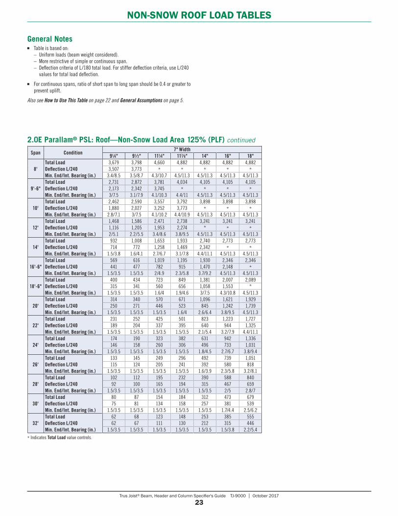
Trus Joist® Beam, Header and Column Specifier's Guide TJ-9000 | October 2017
23
NON-SNOW ROOF LOAD TABLES
General Notes■ Table is based on: – Uniform loads (beam weight considered). – More restrictive of simple or continuous span. – Deflection criteria of L/180 total load. For stiffer deflection criteria, use L/240
values for total load deflection.
■ For continuous spans, ratio of short span to long span should be 0.4 or greater to prevent uplift.
Also see How to Use This Table on page 22 and General Assumptions on page 5.
* Indicates Total Load value controls.
Span Condition7" Width
91⁄4" 91⁄2" 111⁄4" 117⁄8" 14" 16" 18"
8'Total LoadDeflection L/240Min. End/Int. Bearing (in.)
3,679 3,798 4,660 4,882 4,882 4,882 4,8823,507 3,773 * * * * *
3.4/8.5 3.5/8.7 4.3/10.7 4.5/11.3 4.5/11.3 4.5/11.3 4.5/11.3
9'-6"Total LoadDeflection L/240Min. End/Int. Bearing (in.)
2,731 2,872 3,781 4,034 4,105 4,105 4,1052,173 2,342 3,745 * * * *3/7.5 3.1/7.9 4.1/10.3 4.4/11 4.5/11.3 4.5/11.3 4.5/11.3
10'Total LoadDeflection L/240Min. End/Int. Bearing (in.)
2,462 2,590 3,557 3,792 3,898 3,898 3,8981,880 2,027 3,252 3,773 * * *
2.8/7.1 3/7.5 4.1/10.2 4.4/10.9 4.5/11.3 4.5/11.3 4.5/11.3
12'Total LoadDeflection L/240Min. End/Int. Bearing (in.)
1,468 1,586 2,471 2,738 3,241 3,241 3,2411,116 1,205 1,953 2,274 * * *2/5.1 2.2/5.5 3.4/8.6 3.8/9.5 4.5/11.3 4.5/11.3 4.5/11.3
14'Total LoadDeflection L/240Min. End/Int. Bearing (in.)
932 1,008 1,653 1,933 2,740 2,773 2,773714 772 1,258 1,469 2,342 * *
1.5/3.8 1.6/4.1 2.7/6.7 3.1/7.8 4.4/11.1 4.5/11.3 4.5/11.3
16'-6"Total LoadDeflection L/240Min. End/Int. Bearing (in.)
569 616 1,019 1,195 1,930 2,346 2,346441 477 782 915 1,470 2,148 *
1.5/3.5 1.5/3.5 2/4.9 2.3/5.8 3.7/9.2 4.5/11.3 4.5/11.3
18'-6"Total LoadDeflection L/240Min. End/Int. Bearing (in.)
400 434 723 849 1,381 2,007 2,089315 341 560 656 1,058 1,553 *
1.5/3.5 1.5/3.5 1.6/4 1.9/4.6 3/7.5 4.3/10.8 4.5/11.3
20'Total LoadDeflection L/240Min. End/Int. Bearing (in.)
314 340 570 671 1,096 1,621 1,929250 271 446 523 845 1,242 1,739
1.5/3.5 1.5/3.5 1.5/3.5 1.6/4 2.6/6.4 3.8/9.5 4.5/11.3
22'Total LoadDeflection L/240Min. End/Int. Bearing (in.)
231 252 425 501 823 1,223 1,727189 204 337 395 640 944 1,325
1.5/3.5 1.5/3.5 1.5/3.5 1.5/3.5 2.1/5.4 3.2/7.9 4.4/11.1
24'Total LoadDeflection L/240Min. End/Int. Bearing (in.)
174 190 323 382 631 942 1,336146 158 260 306 496 733 1,031
1.5/3.5 1.5/3.5 1.5/3.5 1.5/3.5 1.8/4.5 2.7/6.7 3.8/9.4
26'Total LoadDeflection L/240Min. End/Int. Bearing (in.)
133 145 249 296 492 739 1,051115 124 205 241 392 580 818
1.5/3.5 1.5/3.5 1.5/3.5 1.5/3.5 1.6/3.9 2.3/5.8 3.2/8.1
28'Total LoadDeflection L/240Min. End/Int. Bearing (in.)
102 112 195 232 390 588 84092 100 165 194 315 467 659
1.5/3.5 1.5/3.5 1.5/3.5 1.5/3.5 1.5/3.5 2/5 2.8/7
30'Total LoadDeflection L/240Min. End/Int. Bearing (in.)
80 87 154 184 312 473 67975 81 134 158 257 381 539
1.5/3.5 1.5/3.5 1.5/3.5 1.5/3.5 1.5/3.5 1.7/4.4 2.5/6.2
32'Total LoadDeflection L/240Min. End/Int. Bearing (in.)
62 68 123 148 253 385 55562 67 111 130 212 315 446
1.5/3.5 1.5/3.5 1.5/3.5 1.5/3.5 1.5/3.5 1.5/3.8 2.2/5.4
2.0E Parallam® PSL: Roof—Non-Snow Load Area 125% (PLF) continued
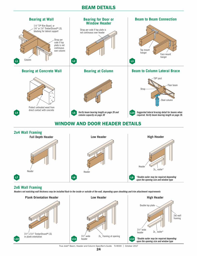
Trus Joist® Beam, Header and Column Specifier's Guide TJ-9000 | October 2017
24
BEAM DETAILS
31⁄2"-wide header
2x_ framing at opening*Double nailer may be required depending upon the opening size and window type
31⁄2" x 51⁄2" TimberStrand® LSL in plank orientation
*Double nailer may be required depending upon the opening size and window type
2x4 Wall Framing
2x6 Wall FramingHeaders not matching wall thickness may be installed flush to the inside or outside of the wall, depending upon sheathing and trim attachment requirements
Verify beam bearing length on page 26 and column capacity on page 30
Strap per code if top plate is not continuous over header
Protect untreated wood from direct contact with concrete
Face mount hanger
Top mount hanger
WINDOW AND DOOR HEADER DETAILS
Bearing at Wall
L1 L2
Bearing for Door or Window Header
L3
Beam to Beam Connection
L4
Bearing at Concrete Wall Bearing at Column
L5
L7 L8 L9
L10 L11 L12
Full Depth Header Low Header High Header
Plank Orientation Header Low Header High Header
Double top plate
2x_ nailer*
2x6 wall framing
31⁄2"-wide header
HeaderHeader2x_ nailer*
Header
TJI® joist
Floor beam
Steel column
Strap
Suggested lateral bracing detail for beams when required. Verify beam bearing length on page 26.
L14
Beam to Column Lateral Brace
Column
11⁄8" TJ® Rim Board, or 1¼" or 1½" TimberStrand® LSL blocking for lateral support
Strap per code if top plate is not continuous over column
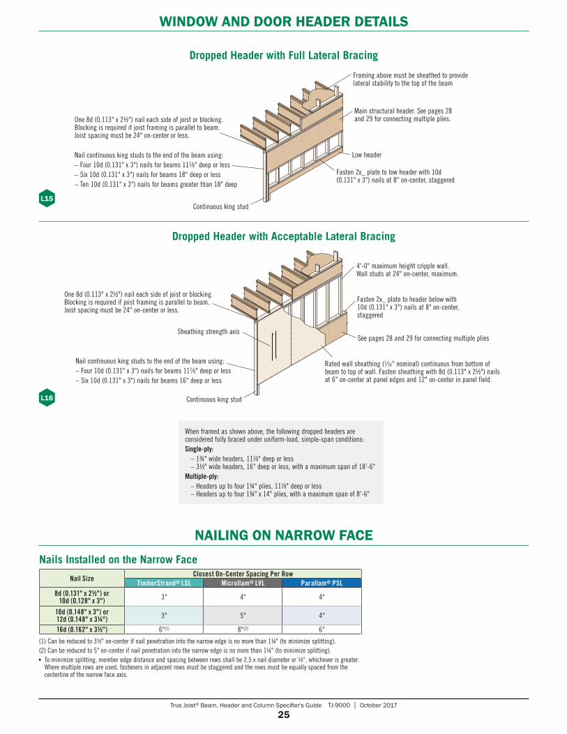
Trus Joist® Beam, Header and Column Specifier's Guide TJ-9000 | October 2017
25
WINDOW AND DOOR HEADER DETAILS
Dropped Header with Full Lateral Bracing
L15
L16
NAILING ON NARROW FACE
Nail SizeClosest On-Center Spacing Per Row
TimberStrand® LSL Microllam® LVL Parallam® PSL8d (0.131" x 21⁄2") or
10d (0.128" x 3") 3" 4" 4"
10d (0.148" x 3") or 12d (0.148" x 31⁄4") 3" 5" 4"
16d (0.162" x 31⁄2") 6"(1) 8"(2) 6"
Nails Installed on the Narrow Face
(1) Can be reduced to 3½" on-center if nail penetration into the narrow edge is no more than 1¼" (to minimize splitting).(2) Can be reduced to 5" on-center if nail penetration into the narrow edge is no more than 1¼" (to minimize splitting).■ To minimize splitting, member edge distance and spacing between rows shall be 2.5 x nail diameter or 3⁄8", whichever is greater.
Where multiple rows are used, fasteners in adjacent rows must be staggered and the rows must be equally spaced from the centerline of the narrow face axis.
See pages 28 and 29 for connecting multiple plies
Continuous king stud
Sheathing strength axis
One 8d (0.113" x 2½") nail each side of joist or blocking. Blocking is required if joist framing is parallel to beam. Joist spacing must be 24" on-center or less.
4'-0" maximum height cripple wall. Wall studs at 24" on-center, maximum.
Fasten 2x_ plate to header below with 10d (0.131" x 3") nails at 8" on-center, staggered
Nail continuous king studs to the end of the beam using:– Four 10d (0.131" x 3") nails for beams 117⁄8" deep or less– Six 10d (0.131" x 3") nails for beams 16" deep or less
Rated wall sheathing (7⁄16" nominal) continuous from bottom of beam to top of wall. Fasten sheathing with 8d (0.113" x 2½") nails at 6" on-center at panel edges and 12" on-center in panel field.
When framed as shown above, the following dropped headers are considered fully braced under uniform-load, simple-span conditions:Single-ply: – 1¾" wide headers, 117⁄8" deep or less – 3½" wide headers, 16" deep or less, with a maximum span of 18'-6"Multiple-ply: – Headers up to four 1¾" plies, 117⁄8" deep or less – Headers up to four 1¾" x 14" plies, with a maximum span of 8'-6"
Dropped Header with Acceptable Lateral Bracing
Framing above must be sheathed to provide lateral stability to the top of the beam
Main structural header. See pages 28 and 29 for connecting multiple plies.
Continuous king stud
One 8d (0.113" x 2½") nail each side of joist or blocking. Blocking is required if joist framing is parallel to beam. Joist spacing must be 24" on-center or less.
Low headerNail continuous king studs to the end of the beam using:– Four 10d (0.131" x 3") nails for beams 117⁄8" deep or less– Six 10d (0.131" x 3") nails for beams 18" deep or less– Ten 10d (0.131" x 3") nails for beams greater than 18" deep
Fasten 2x_ plate to low header with 10d (0.131" x 3") nails at 8" on-center, staggered
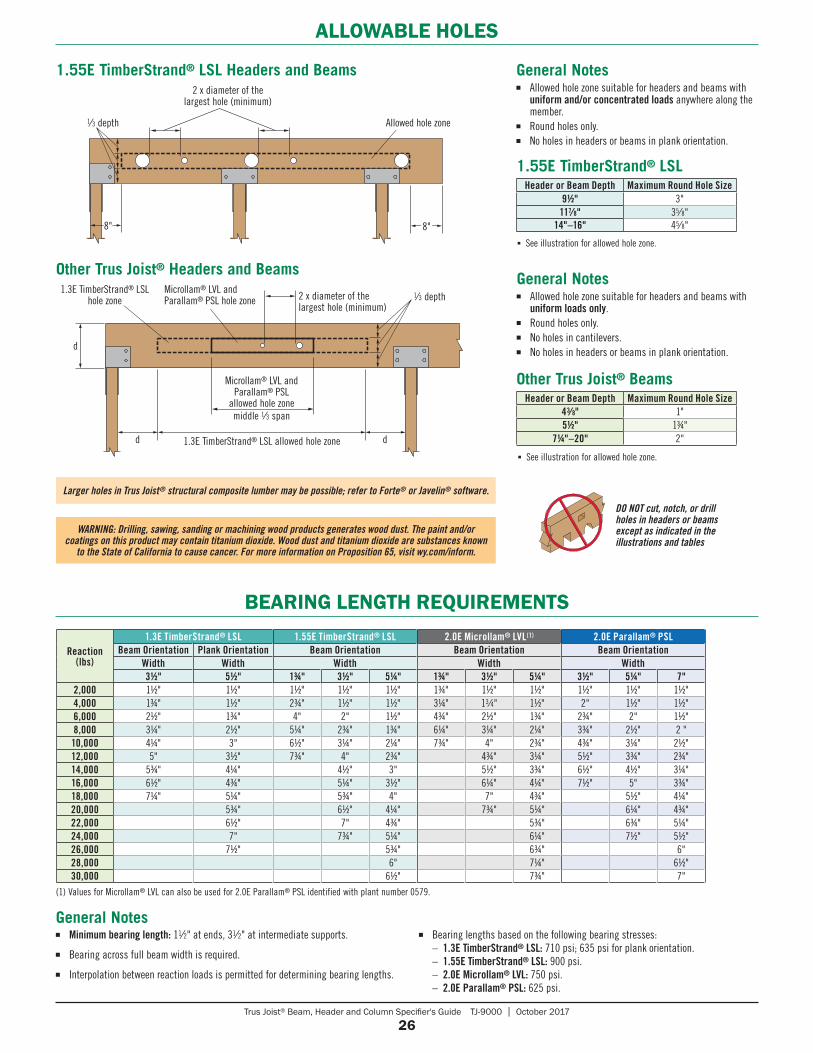
Trus Joist® Beam, Header and Column Specifier's Guide TJ-9000 | October 2017
26
ALLOWABLE HOLES
BEARING LENGTH REQUIREMENTS
Reaction(lbs)
1.3E TimberStrand® LSL 1.55E TimberStrand® LSL 2.0E Microllam® LVL(1) 2.0E Parallam® PSLBeam Orientation Plank Orientation Beam Orientation Beam Orientation Beam Orientation
Width Width Width Width Width31⁄2" 51⁄2" 13⁄4" 31⁄2" 51⁄4" 13⁄4" 31⁄2" 51⁄4" 31⁄2" 51⁄4" 7"
2,000 1½" 1½" 1½" 1½" 1½" 1¾" 1½" 1½" 1½" 1½" 1½"4,000 1¾" 1½" 2¾" 1½" 1½" 3¼" 13⁄4" 1½" 2" 1½" 1½"6,000 2½" 1¾" 4" 2" 1½" 4¾" 2½" 1¾" 2¾" 2" 1½"8,000 3¼" 2½" 5¼" 2¾" 1¾" 6¼" 3¼" 2¼" 3¾" 2½" 2 "10,000 4¼" 3" 6½" 3¼" 2¼" 7¾" 4" 2¾" 4¾" 3¼" 2½"12,000 5" 3½" 7¾" 4" 2¾" 4¾" 3¼" 5½" 3¾" 2¾"14,000 5¾" 4¼" 4½" 3" 5½" 3¾" 6½" 4½" 3¼"16,000 6½" 4¾" 5¼" 3½" 6¼" 4¼" 7½" 5" 3¾"18,000 7¼" 5¼" 5¾" 4" 7" 4¾" 5½" 4¼"20,000 5¾" 6½" 4¼" 7¾" 5¼" 6¼" 4¾"22,000 6½" 7" 4¾" 5¾" 6¾" 5¼"24,000 7" 7¾" 5¼" 6¼" 7½" 5½"26,000 7½" 5¾" 6¾" 6"28,000 6" 7¼" 6½"30,000 6½" 7¾" 7"
■ Minimum bearing length: 11⁄2" at ends, 31⁄2" at intermediate supports.
■ Bearing across full beam width is required.
■ Interpolation between reaction loads is permitted for determining bearing lengths.
■ Bearing lengths based on the following bearing stresses: – 1.3E TimberStrand® LSL: 710 psi; 635 psi for plank orientation. – 1.55E TimberStrand® LSL: 900 psi. – 2.0E Microllam® LVL: 750 psi. – 2.0E Parallam® PSL: 625 psi.
General Notes
DO NOT cut, notch, or drill holes in headers or beams except as indicated in the illustrations and tables
1.55E TimberStrand® LSL Headers and Beams2 x diameter of the
largest hole (minimum)
8"
1⁄3 depth Allowed hole zone
8"
1.55E TimberStrand® LSL
■ See illustration for allowed hole zone.
Header or Beam Depth Maximum Round Hole Size91⁄2" 3"
117⁄8" 35⁄8"14"–16" 45⁄8"
General Notes■ Allowed hole zone suitable for headers and beams with
uniform and/or concentrated loads anywhere along the member.
■ Round holes only.■ No holes in headers or beams in plank orientation.
Other Trus Joist® Headers and Beams
2 x diameter of the largest hole (minimum)
d
Microllam® LVL and Parallam® PSL
allowed hole zonemiddle 1⁄3 span
d
1.3E TimberStrand® LSL hole zone
1⁄3 depthMicrollam® LVL and Parallam® PSL hole zone
1.3E TimberStrand® LSL allowed hole zone
d
General Notes■ Allowed hole zone suitable for headers and beams with
uniform loads only.■ Round holes only.■ No holes in cantilevers.■ No holes in headers or beams in plank orientation.
Other Trus Joist® BeamsHeader or Beam Depth Maximum Round Hole Size
43⁄8" 1"51⁄2" 1¾"
71⁄4"–20" 2"
■ See illustration for allowed hole zone.
WARNING: Drilling, sawing, sanding or machining wood products generates wood dust. The paint and/or coatings on this product may contain titanium dioxide. Wood dust and titanium dioxide are substances known
to the State of California to cause cancer. For more information on Proposition 65, visit wy.com/inform.
Larger holes in Trus Joist® structural composite lumber may be possible; refer to Forte® or Javelin® software.
(1) Values for Microllam® LVL can also be used for 2.0E Parallam® PSL identified with plant number 0579.
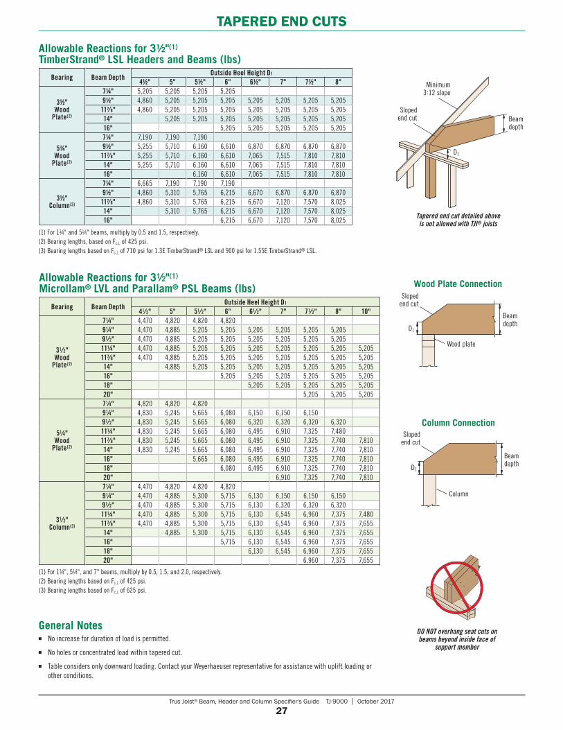
Trus Joist® Beam, Header and Column Specifier's Guide TJ-9000 | October 2017
27
TAPERED END CUTS
DO NOT overhang seat cuts on beams beyond inside face of
support member
Wood Plate ConnectionSloped
end cut
Beam depth
D1
Wood plate
Column Connection
D1
Beam depth
Sloped end cut
Column
(1) For 13⁄4", 51⁄4", and 7" beams, multiply by 0.5, 1.5, and 2.0, respectively.(2) Bearing lengths based on Fc⊥ of 425 psi.(3) Bearing lengths based on Fc⊥ of 625 psi.
Bearing Beam DepthOutside Heel Height D1
41⁄2" 5" 51⁄2" 6" 61⁄2" 7" 71⁄2" 8" 10"
31⁄2" Wood
Plate(2)
71⁄4" 4,470 4,820 4,820 4,82091⁄4" 4,470 4,885 5,205 5,205 5,205 5,205 5,205 5,20591⁄2" 4,470 4,885 5,205 5,205 5,205 5,205 5,205 5,205111⁄4" 4,470 4,885 5,205 5,205 5,205 5,205 5,205 5,205 5,205117⁄8" 4,470 4,885 5,205 5,205 5,205 5,205 5,205 5,205 5,20514" 4,885 5,205 5,205 5,205 5,205 5,205 5,205 5,20516" 5,205 5,205 5,205 5,205 5,205 5,20518" 5,205 5,205 5,205 5,205 5,20520" 5,205 5,205 5,205
51⁄4" Wood
Plate(2)
71⁄4" 4,820 4,820 4,82091⁄4" 4,830 5,245 5,665 6,080 6,150 6,150 6,15091⁄2" 4,830 5,245 5,665 6,080 6,320 6,320 6,320 6,320111⁄4" 4,830 5,245 5,665 6,080 6,495 6,910 7,325 7,480117⁄8" 4,830 5,245 5,665 6,080 6,495 6,910 7,325 7,740 7,81014" 4,830 5,245 5,665 6,080 6,495 6,910 7,325 7,740 7,81016" 5,665 6,080 6,495 6,910 7,325 7,740 7,81018" 6,080 6,495 6,910 7,325 7,740 7,81020" 6,910 7,325 7,740 7,810
31⁄2" Column(3)
71⁄4" 4,470 4,820 4,820 4,82091⁄4" 4,470 4,885 5,300 5,715 6,130 6,150 6,150 6,15091⁄2" 4,470 4,885 5,300 5,715 6,130 6,320 6,320 6,320111⁄4" 4,470 4,885 5,300 5,715 6,130 6,545 6,960 7,375 7,480117⁄8" 4,470 4,885 5,300 5,715 6,130 6,545 6,960 7,375 7,65514" 4,885 5,300 5,715 6,130 6,545 6,960 7,375 7,65516" 5,715 6,130 6,545 6,960 7,375 7,65518" 6,130 6,545 6,960 7,375 7,65520" 6,960 7,375 7,655
Allowable Reactions for 31⁄2"(1) Microllam® LVL and Parallam® PSL Beams (lbs)
Minimum 3:12 slope
Sloped end cut Beam
depth
D1
Tapered end cut detailed above is not allowed with TJI® joists
Bearing Beam DepthOutside Heel Height D1
41⁄2" 5" 51⁄2" 6" 61⁄2" 7" 71⁄2" 8"
31⁄2" Wood
Plate(2)
71⁄4" 5,205 5,205 5,205 5,20591⁄2" 4,860 5,205 5,205 5,205 5,205 5,205 5,205 5,205
117⁄8" 4,860 5,205 5,205 5,205 5,205 5,205 5,205 5,20514" 5,205 5,205 5,205 5,205 5,205 5,205 5,20516" 5,205 5,205 5,205 5,205 5,205
51⁄4" Wood
Plate(2)
71⁄4" 7,190 7,190 7,19091⁄2" 5,255 5,710 6,160 6,610 6,870 6,870 6,870 6,870
117⁄8" 5,255 5,710 6,160 6,610 7,065 7,515 7,810 7,81014" 5,255 5,710 6,160 6,610 7,065 7,515 7,810 7,81016" 6,160 6,610 7,065 7,515 7,810 7,810
31⁄2" Column(3)
71⁄4" 6,665 7,190 7,190 7,19091⁄2" 4,860 5,310 5,765 6,215 6,670 6,870 6,870 6,870
117⁄8" 4,860 5,310 5,765 6,215 6,670 7,120 7,570 8,02514" 5,310 5,765 6,215 6,670 7,120 7,570 8,02516" 6,215 6,670 7,120 7,570 8,025
(1) For 13⁄4" and 51⁄4" beams, multiply by 0.5 and 1.5, respectively.(2) Bearing lengths, based on Fc⊥ of 425 psi.(3) Bearing lengths based on Fc⊥ of 710 psi for 1.3E TimberStrand® LSL and 900 psi for 1.55E TimberStrand® LSL.
■ No increase for duration of load is permitted.
■ No holes or concentrated load within tapered cut.
■ Table considers only downward loading. Contact your Weyerhaeuser representative for assistance with uplift loading or other conditions.
General Notes
Allowable Reactions for 31⁄2"(1) TimberStrand® LSL Headers and Beams (lbs)
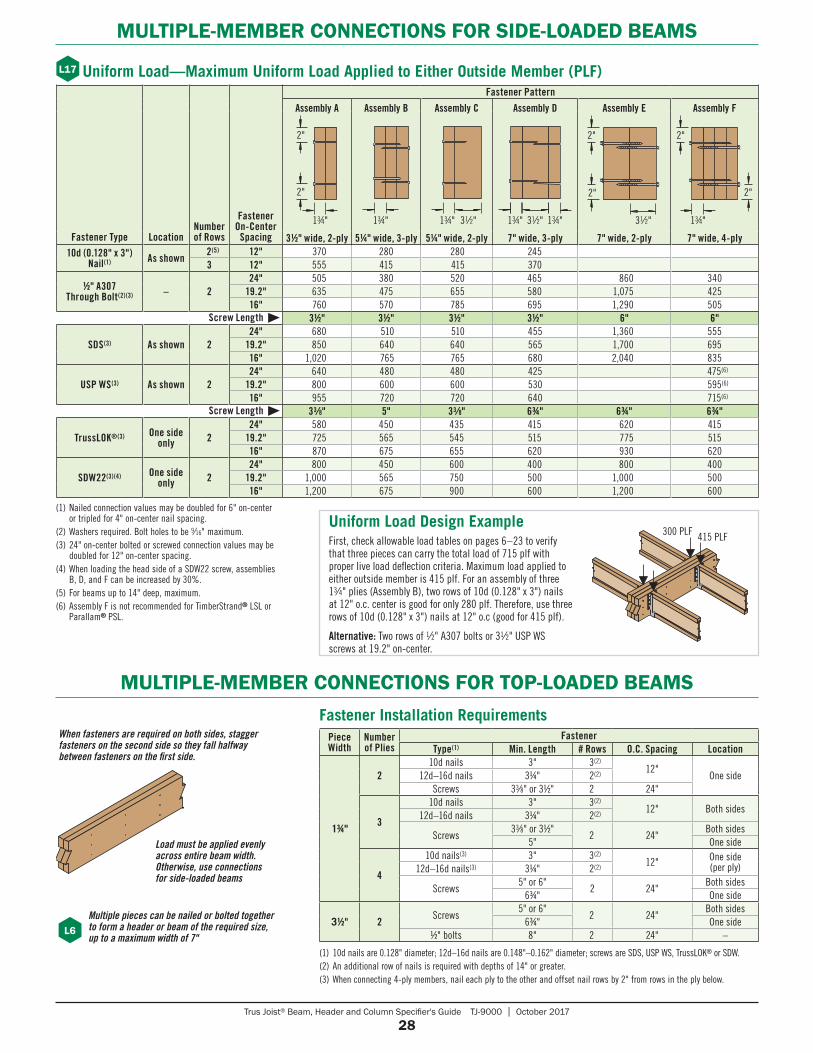
Trus Joist® Beam, Header and Column Specifier's Guide TJ-9000 | October 2017
28
MULTIPLE-MEMBER CONNECTIONS FOR SIDE-LOADED BEAMS
Uniform Load—Maximum Uniform Load Applied to Either Outside Member (PLF)
(1) Nailed connection values may be doubled for 6" on-center or tripled for 4" on-center nail spacing.
(2) Washers required. Bolt holes to be 9⁄16" maximum.(3) 24" on-center bolted or screwed connection values may be
doubled for 12" on-center spacing.(4) When loading the head side of a SDW22 screw, assemblies
B, D, and F can be increased by 30%.(5) For beams up to 14" deep, maximum.(6) Assembly F is not recommended for TimberStrand® LSL or
Parallam® PSL.
MULTIPLE-MEMBER CONNECTIONS FOR TOP-LOADED BEAMS
L17
PieceWidth
Number of Plies
FastenerType(1) Min. Length # Rows O.C. Spacing Location
13⁄4"
210d nails 3" 3(2)
12"One side12d–16d nails 3¼" 2(2)
Screws 33∕8" or 3½" 2 24"
3
10d nails 3" 3(2)12" Both sides
12d–16d nails 3¼" 2(2)
Screws33∕8" or 3½"
2 24"Both sides
5" One side
4
10d nails(3) 3" 3(2)12" One side
(per ply)12d–16d nails(3) 3¼" 2(2)
Screws5" or 6"
2 24"Both sides
6¾" One side
31⁄2" 2Screws
5" or 6"2 24"
Both sides6¾" One side
½" bolts 8" 2 24" –
Fastener Installation Requirements
(1) 10d nails are 0.128" diameter; 12d–16d nails are 0.148"–0.162" diameter; screws are SDS, USP WS, TrussLOK® or SDW.(2) An additional row of nails is required with depths of 14" or greater.(3) When connecting 4-ply members, nail each ply to the other and offset nail rows by 2" from rows in the ply below.
L6
Load must be applied evenly across entire beam width. Otherwise, use connections for side-loaded beams
Multiple pieces can be nailed or bolted together to form a header or beam of the required size, up to a maximum width of 7"
When fasteners are required on both sides, stagger fasteners on the second side so they fall halfway between fasteners on the first side.
Fastener Type LocationNumber of Rows
Fastener On-Center
Spacing
Fastener Pattern
Assembly A Assembly B Assembly C Assembly D Assembly E Assembly F
31⁄2" wide, 2-ply 51⁄4" wide, 3-ply 51⁄4" wide, 2-ply 7" wide, 3-ply 7" wide, 2-ply 7" wide, 4-ply10d (0.128" x 3")
Nail(1) As shown 2(5) 12" 370 280 280 245
3 12" 555 415 415 370
1⁄2" A307 Through Bolt(2)(3) – 2
24" 505 380 520 465 860 34019.2" 635 475 655 580 1,075 42516" 760 570 785 695 1,290 505
Screw Length 31⁄2" 31⁄2" 31⁄2" 31⁄2" 6" 6"
SDS(3) As shown 224" 680 510 510 455 1,360 555
19.2" 850 640 640 565 1,700 69516" 1,020 765 765 680 2,040 835
USP WS(3) As shown 224" 640 480 480 425 475(6)
19.2" 800 600 600 530 595(6)
16" 955 720 720 640 715(6)
Screw Length 33⁄8" 5" 33⁄8" 63⁄4" 63⁄4" 63⁄4"
TrussLOK®(3) One side only 2
24" 580 450 435 415 620 41519.2" 725 565 545 515 775 51516" 870 675 655 620 930 620
SDW22(3)(4) One side only 2
24" 800 450 600 400 800 40019.2" 1,000 565 750 500 1,000 50016" 1,200 675 900 600 1,200 600
2"
2"
13⁄4" 13⁄4" 13⁄4" 31⁄2" 13⁄4" 31⁄2" 13⁄4"
2"
2"
31⁄2" 13⁄4"
2"
2"
First, check allowable load tables on pages 6 – 23 to verify that three pieces can carry the total load of 715 plf with proper live load deflection criteria. Maximum load applied to either outside member is 415 plf. For an assembly of three 13⁄4" plies (Assembly B), two rows of 10d (0.128" x 3") nails at 12" o.c. center is good for only 280 plf. Therefore, use three rows of 10d (0.128" x 3") nails at 12" o.c (good for 415 plf).
Alternative: Two rows of 1⁄2" A307 bolts or 31⁄2" USP WS screws at 19.2" on-center.
Uniform Load Design Example300 PLF 415 PLF
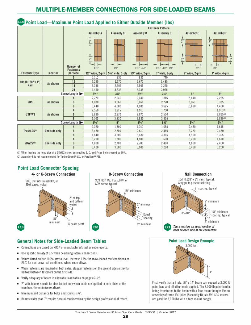
Trus Joist® Beam, Header and Column Specifier's Guide TJ-9000 | October 2017
29
MULTIPLE-MEMBER CONNECTIONS FOR SIDE-LOADED BEAMS
2"
Point Load—Maximum Point Load Applied to Either Outside Member (lbs)L18
(1) When loading the head side of a SDW22 screw, assemblies B, D, and F can be increased by 30%.(2) Assembly F is not recommended for TimberStrand® LSL or Parallam® PSL.
Fastener Type Location
Number of Fasteners per Side
Fastener Pattern
Assembly A Assembly B Assembly C Assembly D Assembly E Assembly F
31⁄2" wide, 2-ply 51⁄4" wide, 3-ply 51⁄4" wide, 2-ply 7" wide, 3-ply 7" wide, 2-ply 7" wide, 4-ply
10d (0.128" x 3") Nail As shown
6 1,110 835 835 74012 2,225 1,670 1,670 1,48518 3,335 2,505 2,505 2,22524 4,450 3,335 3,335 2,965
Screw Length 31⁄2" 31⁄2" 31⁄2" 31⁄2" 6" 6"
SDS As shown4 2,720 2,040 2,040 1,815 5,440 2,2256 4,080 3,060 3,060 2,720 8,160 3,3358 5,440 4,080 4,080 3,625 10,880 4,450
USP WS As shown4 2,550 1,915 1,915 1,700 1,910(2)
6 3,830 2,870 2,870 2,550 2,865(2)
8 5,105 3,830 3,830 3,405 3,820(2)
Screw Length 33⁄8" 5" 33⁄8" 63⁄4" 63⁄4" 63⁄4"
TrussLOK® One side only4 2,320 1,800 1,740 1,655 2,480 1,6556 3,480 2,700 2,610 2,480 3,720 2,4808 4,640 3,600 3,480 3,305 4,960 3,305
SDW22(1) One side only4 3,200 1,800 1,800 1,600 3,200 1,6006 4,800 2,700 2,700 2,400 4,800 2,4008 6,400 3,600 3,600 3,200 6,400 3,200
2"
2"
13⁄4" 13⁄4" 13⁄4" 31⁄2" 31⁄2"
2"
2"
31⁄2" 13⁄4"
2"
2"
13⁄4"13⁄4"
General Notes for Side-Loaded Beam Tables■ Connections are based on NDS® or manufacturer’s test or code reports.■ Use specific gravity of 0.5 when designing lateral connections.■ Values listed are for 100% stress level. Increase 15% for snow-loaded roof conditions or
25% for non-snow roof conditions, where code allows.■ When fasteners are required on both sides, stagger fasteners on the second side so they fall
halfway between fasteners on the first side.
■ Verify adequacy of beam in allowable load tables on pages 6 – 23.■ 7" wide beams should be side-loaded only when loads are applied to both sides of the
members (to minimize rotation).■ Minimum end distance for bolts and screws is 6".■ Beams wider than 7" require special consideration by the design professional of record.
Point Load Connector Spacing
First, verify that a 3-ply, 1¾" x 14" beam can support a 3,000 lb point load and all other loads applied. The 3,000 lb point load is being trans ferred to the beam with a face mount hanger. For an assembly of three 1¾" plies (Assembly B), six 3½" SDS screws are good for 3,060 lbs with a face mount hanger.
Point Load Design Example3,000 lbs
14"
4- or 6-Screw Connection 8-Screw Connection Nail Connection
L19 L20 There must be an equal number of nails on each side of the connection
L212" minimum
Equal spacing
1½" minimum
2" minimum
1½" minimum spacing, typical
2" spacing, typical
8"–10"
2" minimum
10d (0.128" x 3") nails, typical. Stagger to prevent splitting.
2" at top and bottom, typical
½ beam depth
SDS, USP WS, TrussLOK®, or SDW screw, typical
1½" minimum
SDS, USP WS, TrussLOK®, or SDW screw, typical
2" minimum
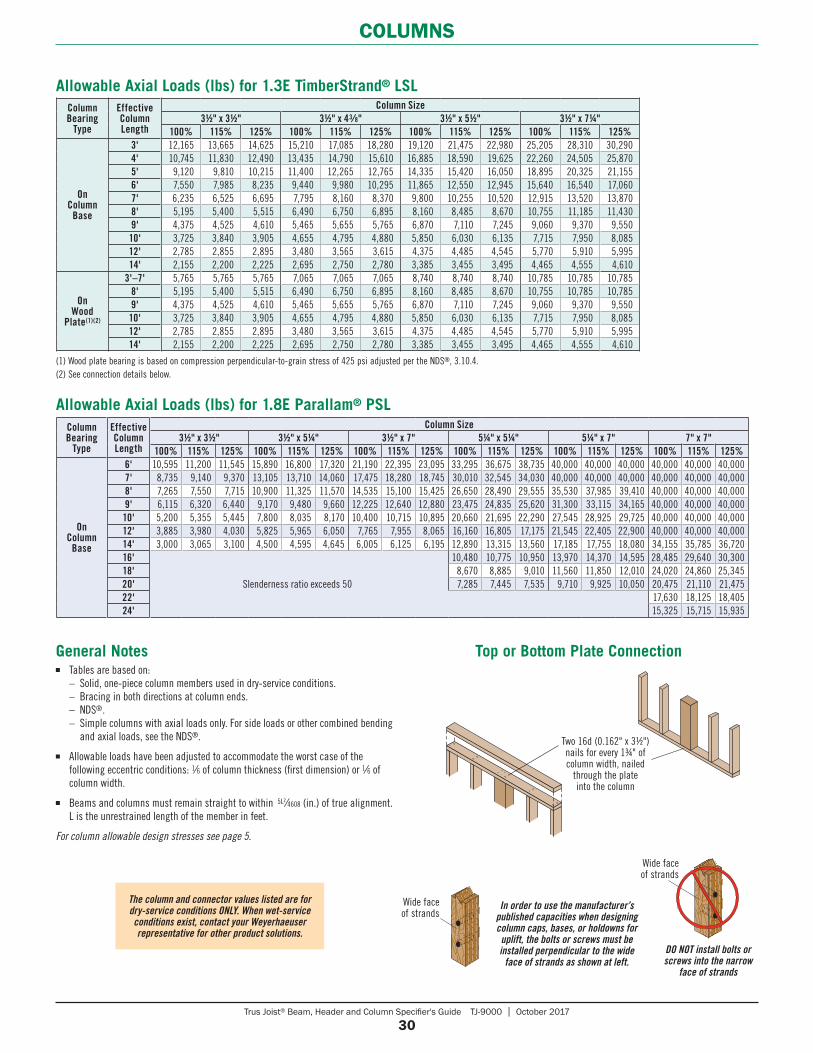
Trus Joist® Beam, Header and Column Specifier's Guide TJ-9000 | October 2017
30
COLUMNS
Column Bearing
Type
Effective Column Length
Column Size31⁄2" x 31⁄2" 31⁄2" x 43⁄8" 31⁄2" x 51⁄2" 31⁄2" x 71⁄4"
100% 115% 125% 100% 115% 125% 100% 115% 125% 100% 115% 125%
On Column
Base
3' 12,165 13,665 14,625 15,210 17,085 18,280 19,120 21,475 22,980 25,205 28,310 30,2904' 10,745 11,830 12,490 13,435 14,790 15,610 16,885 18,590 19,625 22,260 24,505 25,8705' 9,120 9,810 10,215 11,400 12,265 12,765 14,335 15,420 16,050 18,895 20,325 21,1556' 7,550 7,985 8,235 9,440 9,980 10,295 11,865 12,550 12,945 15,640 16,540 17,0607' 6,235 6,525 6,695 7,795 8,160 8,370 9,800 10,255 10,520 12,915 13,520 13,8708' 5,195 5,400 5,515 6,490 6,750 6,895 8,160 8,485 8,670 10,755 11,185 11,4309' 4,375 4,525 4,610 5,465 5,655 5,765 6,870 7,110 7,245 9,060 9,370 9,55010' 3,725 3,840 3,905 4,655 4,795 4,880 5,850 6,030 6,135 7,715 7,950 8,08512' 2,785 2,855 2,895 3,480 3,565 3,615 4,375 4,485 4,545 5,770 5,910 5,99514' 2,155 2,200 2,225 2,695 2,750 2,780 3,385 3,455 3,495 4,465 4,555 4,610
On Wood
Plate(1)(2)
3'–7' 5,765 5,765 5,765 7,065 7,065 7,065 8,740 8,740 8,740 10,785 10,785 10,7858' 5,195 5,400 5,515 6,490 6,750 6,895 8,160 8,485 8,670 10,755 10,785 10,7859' 4,375 4,525 4,610 5,465 5,655 5,765 6,870 7,110 7,245 9,060 9,370 9,55010' 3,725 3,840 3,905 4,655 4,795 4,880 5,850 6,030 6,135 7,715 7,950 8,08512' 2,785 2,855 2,895 3,480 3,565 3,615 4,375 4,485 4,545 5,770 5,910 5,99514' 2,155 2,200 2,225 2,695 2,750 2,780 3,385 3,455 3,495 4,465 4,555 4,610
Column Bearing
Type
Effective Column Length
Column Size31⁄2" x 31⁄2" 31⁄2" x 51⁄4" 31⁄2" x 7" 51⁄4" x 51⁄4" 51⁄4" x 7" 7" x 7"
100% 115% 125% 100% 115% 125% 100% 115% 125% 100% 115% 125% 100% 115% 125% 100% 115% 125%
On Column
Base
6' 10,595 11,200 11,545 15,890 16,800 17,320 21,190 22,395 23,095 33,295 36,675 38,735 40,000 40,000 40,000 40,000 40,000 40,0007' 8,735 9,140 9,370 13,105 13,710 14,060 17,475 18,280 18,745 30,010 32,545 34,030 40,000 40,000 40,000 40,000 40,000 40,0008' 7,265 7,550 7,715 10,900 11,325 11,570 14,535 15,100 15,425 26,650 28,490 29,555 35,530 37,985 39,410 40,000 40,000 40,0009' 6,115 6,320 6,440 9,170 9,480 9,660 12,225 12,640 12,880 23,475 24,835 25,620 31,300 33,115 34,165 40,000 40,000 40,00010' 5,200 5,355 5,445 7,800 8,035 8,170 10,400 10,715 10,895 20,660 21,695 22,290 27,545 28,925 29,725 40,000 40,000 40,00012' 3,885 3,980 4,030 5,825 5,965 6,050 7,765 7,955 8,065 16,160 16,805 17,175 21,545 22,405 22,900 40,000 40,000 40,00014' 3,000 3,065 3,100 4,500 4,595 4,645 6,005 6,125 6,195 12,890 13,315 13,560 17,185 17,755 18,080 34,155 35,785 36,72016'
Slenderness ratio exceeds 50
10,480 10,775 10,950 13,970 14,370 14,595 28,485 29,640 30,30018' 8,670 8,885 9,010 11,560 11,850 12,010 24,020 24,860 25,34520' 7,285 7,445 7,535 9,710 9,925 10,050 20,475 21,110 21,47522' 17,630 18,125 18,40524' 15,325 15,715 15,935
Allowable Axial Loads (lbs) for 1.8E Parallam® PSL
Allowable Axial Loads (lbs) for 1.3E TimberStrand® LSL
(1) Wood plate bearing is based on compression perpendicular-to-grain stress of 425 psi adjusted per the NDS®, 3.10.4.(2) See connection details below.
General Notes■ Tables are based on: – Solid, one-piece column members used in dry-service conditions. – Bracing in both directions at column ends. – NDS®. – Simple columns with axial loads only. For side loads or other combined bending
and axial loads, see the NDS®.
■ Allowable loads have been adjusted to accommodate the worst case of the following eccentric conditions: 1⁄6 of column thickness (first dimension) or 1⁄6 of column width.
■ Beams and columns must remain straight to within 5L2⁄4608 (in.) of true alignment. L is the unrestrained length of the member in feet.
For column allowable design stresses see page 5.
The column and connector values listed are for dry-service conditions ONLY. When wet-service conditions exist, contact your Weyerhaeuser representative for other product solutions.
In order to use the manufacturer’s published capacities when designing column caps, bases, or holdowns for uplift, the bolts or screws must be installed perpendicular to the wide
face of strands as shown at left.
Wide face of strands
Wide face of strands
DO NOT install bolts or screws into the narrow
face of strands
Two 16d (0.162" x 3½") nails for every 1¾" of column width, nailed
through the plate into the column
Top or Bottom Plate Connection
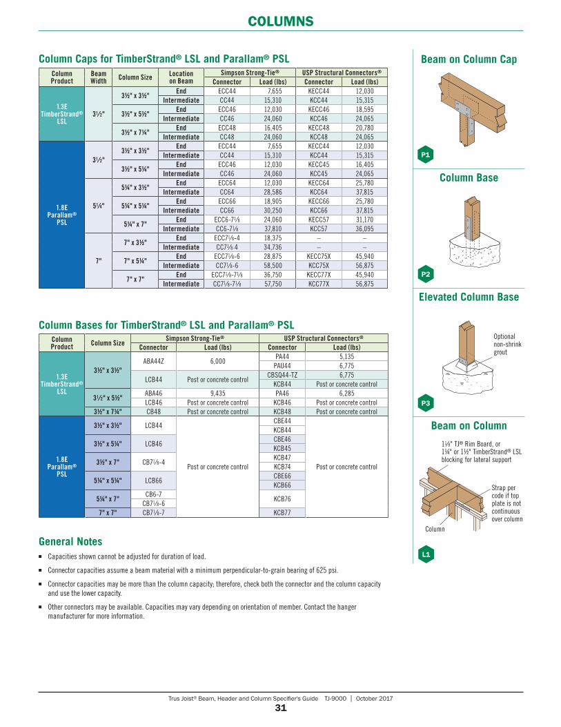
Trus Joist® Beam, Header and Column Specifier's Guide TJ-9000 | October 2017
31
COLUMNS
Column Caps for TimberStrand® LSL and Parallam® PSLColumn Product
Beam Width Column Size Location
on BeamSimpson Strong-Tie® USP Structural Connectors®
Connector Load (lbs) Connector Load (lbs)
1.3E TimberStrand®
LSL31⁄2"
31⁄2" x 31⁄2"End ECC44 7,655 KECC44 12,030
Intermediate CC44 15,310 KCC44 15,315
31⁄2" x 51⁄2"End ECC46 12,030 KECC46 18,595
Intermediate CC46 24,060 KCC46 24,065
31⁄2" x 71⁄4"End ECC48 16,405 KECC48 20,780
Intermediate CC48 24,060 KCC48 24,065
1.8E Parallam®
PSL
31⁄2"31⁄2" x 31⁄2"
End ECC44 7,655 KECC44 12,030Intermediate CC44 15,310 KCC44 15,315
31⁄2" x 51⁄4"End ECC46 12,030 KECC45 16,405
Intermediate CC46 24,060 KCC45 24,065
51⁄4"
51⁄4" x 31⁄2"End ECC64 12,030 KECC64 25,780
Intermediate CC64 28,586 KCC64 37,815
51⁄4" x 51⁄4"End ECC66 18,905 KECC66 25,780
Intermediate CC66 30,250 KCC66 37,815
51⁄4" x 7"End ECC6-71⁄8 24,060 KECC57 31,170
Intermediate CC6-71⁄8 37,810 KCC57 36,095
7"
7" x 31⁄2"End ECC71⁄8-4 18,375 – –
Intermediate CC71⁄8-4 34,736 – –
7" x 51⁄4"End ECC71⁄8-6 28,875 KECC75X 45,940
Intermediate CC71⁄8-6 58,500 KCC75X 56,875
7" x 7"End ECC71⁄8-71⁄8 36,750 KECC77X 45,940
Intermediate CC71⁄8-71⁄8 57,750 KCC77X 56,875
Column Product Column Size
Simpson Strong-Tie® USP Structural Connectors®
Connector Load (lbs) Connector Load (lbs)
1.3E TimberStrand®
LSL
31⁄2" x 31⁄2"ABA44Z 6,000
PA44 5,135PAU44 6,775
LCB44 Post or concrete controlCBSQ44-TZ 6,775
KCB44 Post or concrete control
31⁄2" x 51⁄2"ABA46 9,435 PA46 6,285LCB46 Post or concrete control KCB46 Post or concrete control
31⁄2" x 71⁄4" CB48 Post or concrete control KCB48 Post or concrete control
1.8E Parallam®
PSL
31⁄2" x 31⁄2" LCB44
Post or concrete control
CBE44
Post or concrete control
KCB44
31⁄2" x 51⁄4" LCB46CBE46KCB45
31⁄2" x 7" CB71⁄8-4KCB47KCB74
51⁄4" x 51⁄4" LCB66CBE66KCB66
51⁄4" x 7"CB6-7
KCB76CB71⁄8-6
7" x 7" CB71⁄8-7 KCB77
General Notes ■ Capacities shown cannot be adjusted for duration of load.
■ Connector capacities assume a beam material with a minimum perpendicular-to-grain bearing of 625 psi.
■ Connector capacities may be more than the column capacity; therefore, check both the connector and the column capacity and use the lower capacity.
■ Other connectors may be available. Capacities may vary depending on orientation of member. Contact the hanger manufacturer for more information.
Column Bases for TimberStrand® LSL and Parallam® PSL
Beam on Column Cap
P1
Column Base
P2
Elevated Column Base
Optionalnon-shrinkgrout
P3
Beam on Column
L1
Column
11⁄8" TJ® Rim Board, or 1¼" or 1½" TimberStrand® LSL blocking for lateral support
Strap per code if top plate is not continuous over column
October 2017 • Reorder TJ-9000 , Weyerhaeuser, Microllam, Parallam, TimberStrand, TJ, TJI, and Trus Joist are registered trademarks and Edge Gold is a trademark of Weyerhaeuser NR. © 2017 Weyerhaeuser NR Company. All rights reserved. Printed in the USA.
This document supersedes all previous versions. If this is more than one year old, contact your dealer or Weyerhaeuser rep.
You want to build solid and durable structures—we want to help. Weyerhaeuser provides high-quality building products and unparalleled technical and field assistance to support you and your project from start to finish.
Floors and Roofs: Start with the best framing components in the industry: our Trus Joist® TJI® joists; TimberStrand® LSL rim board; and TimberStrand® LSL, Microllam® LVL, and Parallam® PSL headers and beams. Pull them all together with our self-gapping and self-draining Weyerhaeuser Edge GoldTM floor panels and durable Weyerhaeuser roof sheathing.
Walls: Get the best value out of your framing package—use TimberStrand® LSL studs for tall walls, kitchens, and bathrooms, and our traditional, solid-sawn lumber everywhere else. Cut down installation time by using TimberStrand® LSL headers for doors and windows, and Weyerhaeuser wall sheathing with its handy two-way nail lines.
Software Solutions: Whether you are a design professional or lumber dealer, Weyerhaeuser offers an array of software packages to help you specify individual framing members, create cut lists, manage inventories—even help you design a complete structural frame. Contact your Weyerhaeuser representative to find out how to get the software you need.
Technical Support: Need technical help? Weyerhaeuser has one of the largest networks of engineers and sales representatives in the business. Call us for help, and a skilled member from our team of experts will answer your questions and work with you to develop solutions that meet all your structural framing needs.
WE CAN HELP YOU BUILD SMARTER
CONTACT US
1.888.453.8358 • weyerhaeuser.com/woodproducts/contact
Contact your local representative or dealer at:
Visit weyerhaeuser.com/woodproducts/warranty for copies of this and other Trus Joist® Engineered Wood Product warranties.
Weyerhaeuser provides a limited warranty for the expected life of the structure for all Trus Joist® branded products. Product information, installation instructions, and the full text of each product's limited warranty (including limitations and exclusions) are available on the Weyerhaeuser website, from your Weyerhaeuser representative, or by calling toll free: 888-453-8358.
Additionally, Weyerhaeuser offers limited warranties on a broad variety of its other products. To see complete details of all Weyerhaeuser product warranties, visit weyerhaeuser.com/wood products/warranty.
1.888.453.8358 WEYERHAEUSER.COM/WOODPRODUCTS
PRODUCT WARRANTYL I M I T E D L I F E T I M E
Reorder TJ-1010 December 2016 , Weyerhaeuser, and Trus Joist are registered trademarks of Weyerhaeuser NR. © 2016 Weyerhaeuser NR Company. All rights reserved.