Beamforming for Radar Systems on COTS … · Downconversion Beamformer Partial-Sum Pulse...
33
Beamforming for Radar Systems on COTS Heterogeneous Computing Platforms Mr. Jeffrey Rudin Mercury Computer Systems, Inc. Phone: (978) 967-1686 Fax: (978) 256-8596 Email: [email protected] Abstract: The introduction of high-speed analog-to-digital converters has resulted in many of the traditional front-end and sub-array combining functions of multi-function, phased-array radar systems being performed in the digital rather than in the analog domain. Due to the intense amount of processing that is required, many of these functions had to be realized in hardware. This was originally accomplished using VLSI ASICs. However, the advent of multi-million gate field-programmable gate array (FPGA) has permitted these complex digital processing functions to be put in small packages with a degree of design flexibility that is normally associated only with software. This permits more of the radar functions to be realized in commercial off-the- shelf (COTS) hardware by obviating the need of full-custom VLSI in many cases. The incorporation of FPGA technology into COTS processing subsystems permits more complex designs to be created than could be achieved by general-purpose or digital signal processors alone. Simply incorporating FPGAs into single board computers could solve many signal processing problems. However, because of the complexity of the signal processing in a multi- function radar system, a distributed, parallel-processing architecture is usually required. In addition, the trend toward an increasing number of input channels and the formation of a greater number of simultaneous beams requires a high degree of interconnection among the processing elements. Therefore, the technology used to interconnect the computing elements must be flexible enough to accommodate different architectures and system requirements. Furthermore, the interconnection technology should be scalable enough to enable early design prototyping as well as system deployment over a wide range of mission platforms.
Transcript of Beamforming for Radar Systems on COTS … · Downconversion Beamformer Partial-Sum Pulse...

Beamforming for Radar Systems on COTS Heterogeneous Computing Platforms Mr. Jeffrey Rudin
Mercury Computer Systems, Inc. Phone: (978) 967-1686 Fax: (978) 256-8596
Email: [email protected]
Abstract: The introduction of high-speed analog-to-digital converters has resulted in many of the traditional front-end and sub-array combining functions of multi-function, phased-array radar systems being performed in the digital rather than in the analog domain. Due to the intense amount of processing that is required, many of these functions had to be realized in hardware. This was originally accomplished using VLSI ASICs. However, the advent of multi-million gate field-programmable gate array (FPGA) has permitted these complex digital processing functions to be put in small packages with a degree of design flexibility that is normally associated only with software. This permits more of the radar functions to be realized in commercial off-the-shelf (COTS) hardware by obviating the need of full-custom VLSI in many cases. The incorporation of FPGA technology into COTS processing subsystems permits more complex designs to be created than could be achieved by general-purpose or digital signal processors alone. Simply incorporating FPGAs into single board computers could solve many signal processing problems. However, because of the complexity of the signal processing in a multi-function radar system, a distributed, parallel-processing architecture is usually required. In addition, the trend toward an increasing number of input channels and the formation of a greater number of simultaneous beams requires a high degree of interconnection among the processing elements. Therefore, the technology used to interconnect the computing elements must be flexible enough to accommodate different architectures and system requirements. Furthermore, the interconnection technology should be scalable enough to enable early design prototyping as well as system deployment over a wide range of mission platforms.
Report Documentation Page Form ApprovedOMB No. 0704-0188
Public reporting burden for the collection of information is estimated to average 1 hour per response, including the time for reviewing instructions, searching existing data sources, gathering andmaintaining the data needed, and completing and reviewing the collection of information. Send comments regarding this burden estimate or any other aspect of this collection of information,including suggestions for reducing this burden, to Washington Headquarters Services, Directorate for Information Operations and Reports, 1215 Jefferson Davis Highway, Suite 1204, ArlingtonVA 22202-4302. Respondents should be aware that notwithstanding any other provision of law, no person shall be subject to a penalty for failing to comply with a collection of information if itdoes not display a currently valid OMB control number.
1. REPORT DATE 20 AUG 2004
2. REPORT TYPE N/A
3. DATES COVERED -
4. TITLE AND SUBTITLE Beamforming for Radar Systems on COTS Heterogeneous Computing Platforms
5a. CONTRACT NUMBER
5b. GRANT NUMBER
5c. PROGRAM ELEMENT NUMBER
6. AUTHOR(S) 5d. PROJECT NUMBER
5e. TASK NUMBER
5f. WORK UNIT NUMBER
7. PERFORMING ORGANIZATION NAME(S) AND ADDRESS(ES) Mercury Computer Systems, Inc.
8. PERFORMING ORGANIZATIONREPORT NUMBER
9. SPONSORING/MONITORING AGENCY NAME(S) AND ADDRESS(ES) 10. SPONSOR/MONITOR’S ACRONYM(S)
11. SPONSOR/MONITOR’S REPORT NUMBER(S)
12. DISTRIBUTION/AVAILABILITY STATEMENT Approved for public release, distribution unlimited
13. SUPPLEMENTARY NOTES See also ADM001694, HPEC-6-Vol 1 ESC-TR-2003-081; High Performance Embedded Computing(HPEC) Workshop (7th)., The original document contains color images.
14. ABSTRACT
15. SUBJECT TERMS
16. SECURITY CLASSIFICATION OF: 17. LIMITATION OF ABSTRACT
UU
18. NUMBEROF PAGES
32
19a. NAME OFRESPONSIBLE PERSON
a. REPORT unclassified
b. ABSTRACT unclassified
c. THIS PAGE unclassified
Standard Form 298 (Rev. 8-98) Prescribed by ANSI Std Z39-18
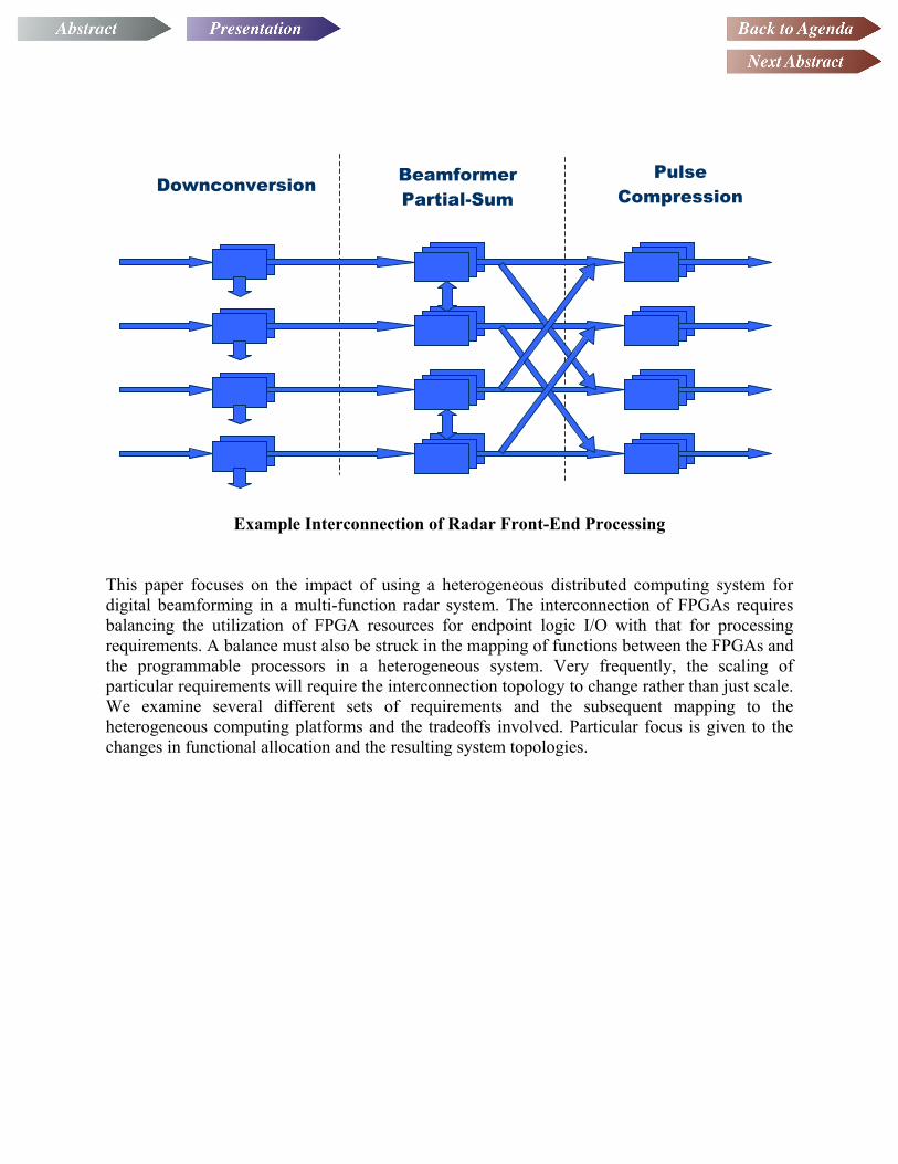
Downconversion BeamformerPartial-Sum
Pulse Compression
Example Interconnection of Radar Front-End Processing
This paper focuses on the impact of using a heterogeneous distributed computing system for digital beamforming in a multi-function radar system. The interconnection of FPGAs requires balancing the utilization of FPGA resources for endpoint logic I/O with that for processing requirements. A balance must also be struck in the mapping of functions between the FPGAs and the programmable processors in a heterogeneous system. Very frequently, the scaling of particular requirements will require the interconnection topology to change rather than just scale. We examine several different sets of requirements and the subsequent mapping to the heterogeneous computing platforms and the tradeoffs involved. Particular focus is given to the changes in functional allocation and the resulting system topologies.
© 2003 Mercury Computer Systems, Inc.
Beamforming for Radar Systems on COTS
Heterogeneous Computing Platforms
Beamforming for Radar Beamforming for Radar Systems on COTS Systems on COTS
Heterogeneous Computing Heterogeneous Computing PlatformsPlatformsJeffrey A. Rudin
Mercury Computer Systems, Inc.
High Performance Embedded Computing (HPEC) ConferenceSeptember 23, 2003
2© 2003 Mercury Computer Systems, Inc.
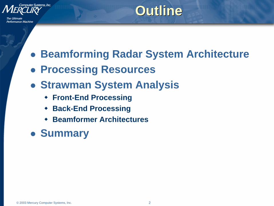
OutlineOutline
Beamforming Radar System ArchitectureProcessing ResourcesStrawman System Analysis
Front-End ProcessingBack-End ProcessingBeamformer Architectures
Summary

3© 2003 Mercury Computer Systems, Inc.
Radar System ArchitectureRadar System Architecture
Beamforming requires massive dataflow and computationADC precision and data rate are chosen to provide high dynamic range and and wide signal bandwidthHigh number of input channels required in modern phased array radars to produce multiple beams and nulls
Digital Memory
Pulse Compression
AdaptiveBeamformerADC Front-End
RF Combiner
Pulse Compression
AdaptiveBeamformerADC Front-End
RF Combiner
Pulse Compression
AdaptiveBeamformerADC Front-End
RF Combiner
Pulse Compression
AdaptiveBeamformerADC Front-End
RF Combiner
Pulse Compression
AdaptiveBeamformerADC Front-End
RF Combiner
Sub-ArrayBeamformer
ANALOG FPGA µ-P

4© 2003 Mercury Computer Systems, Inc.
Processing ResourcesProcessing Resources
MicroprocessorsFixed processing, I/O, and memory architectureTask context switch requires microsecondsNative floating-point availableLow interaction between code modules
FPGAsCustomizable processing, I/O, and memory architectureTask context switch requires reconfiguration -- millisecondsFloating-point must be built or boughtConsiderable interaction between IP coresSignal propagation issuesCurrently harder to program than microprocessors
5© 2003 Mercury Computer Systems, Inc.
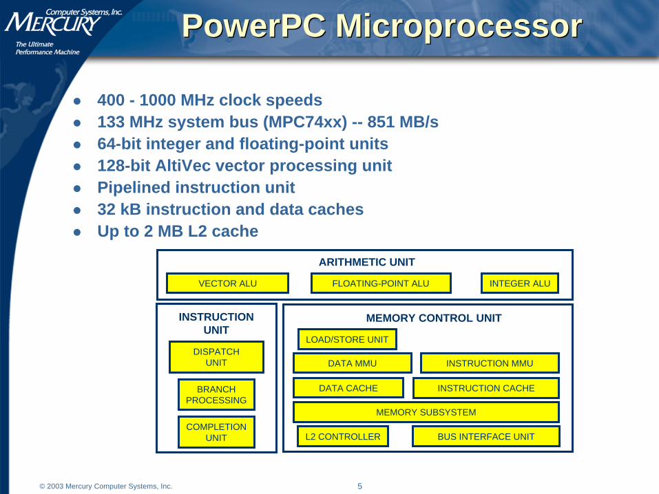
PowerPC MicroprocessorPowerPC Microprocessor
400 - 1000 MHz clock speeds133 MHz system bus (MPC74xx) -- 851 MB/s64-bit integer and floating-point units128-bit AltiVec vector processing unitPipelined instruction unit32 kB instruction and data cachesUp to 2 MB L2 cache
INSTRUCTION MMUDATA MMU
DATA CACHE INSTRUCTION CACHE
L2 CONTROLLER
LOAD/STORE UNIT
BUS INTERFACE UNIT
MEMORY SUBSYSTEM
MEMORY CONTROL UNIT
COMPLETIONUNIT
DISPATCHUNIT
BRANCHPROCESSING
INSTRUCTIONUNIT
VECTOR ALU INTEGER ALUFLOATING-POINT ALU
ARITHMETIC UNIT
6© 2003 Mercury Computer Systems, Inc.
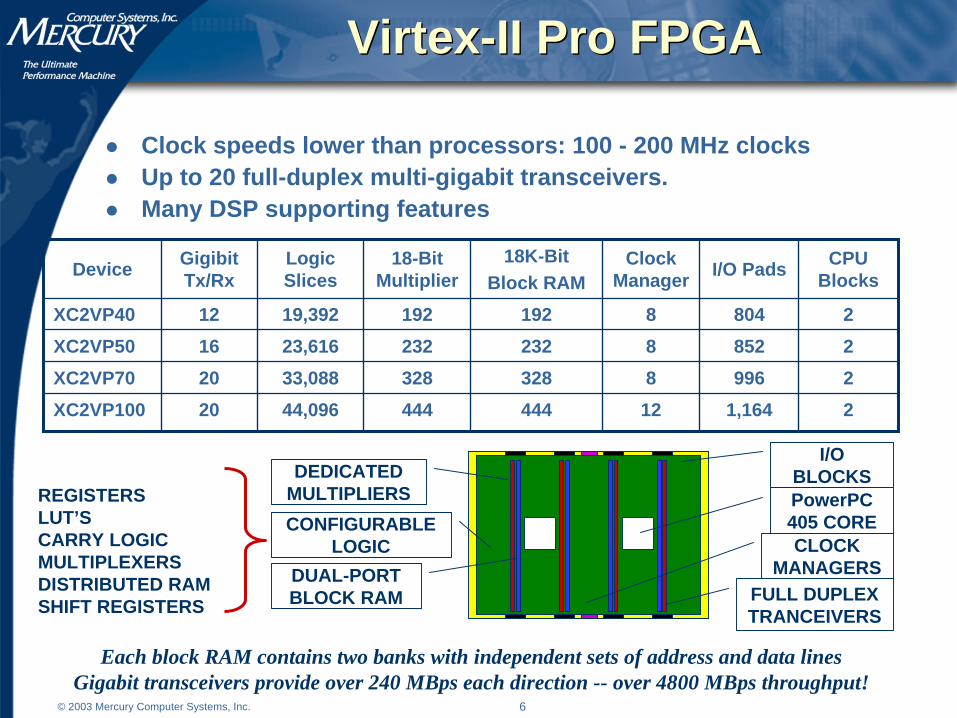
21,1641244444444,09620XC2VP100
2996832832833,08820XC2VP70
2852823223223,61616XC2VP50
2804819219219,39212XC2VP40
CPU BlocksI/O PadsClock
Manager18K-Bit
Block RAM18-Bit
MultiplierLogic Slices
Gigibit Tx/RxDevice
Virtex-II Pro FPGAVirtex-II Pro FPGA
Clock speeds lower than processors: 100 - 200 MHz clocksUp to 20 full-duplex multi-gigabit transceivers.Many DSP supporting features
PowerPC 405 CORE
FULL DUPLEX TRANCEIVERS
DUAL-PORTBLOCK RAM
CONFIGURABLELOGIC CLOCK
MANAGERS
I/O BLOCKSDEDICATED
MULTIPLIERSREGISTERSLUT’SCARRY LOGICMULTIPLEXERSDISTRIBUTED RAMSHIFT REGISTERS
Each block RAM contains two banks with independent sets of address and data linesGigabit transceivers provide over 240 MBps each direction -- over 4800 MBps throughput!
7© 2003 Mercury Computer Systems, Inc.
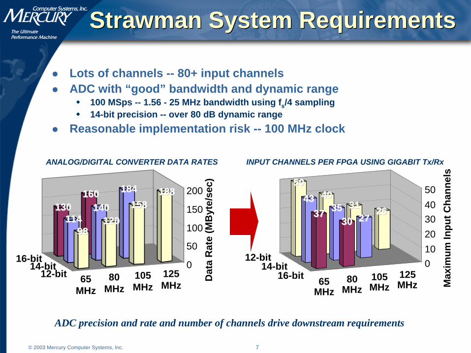
Strawman System RequirementsStrawman System Requirements
Lots of channels -- 80+ input channelsADC with “good” bandwidth and dynamic range
100 MSps -- 1.56 - 25 MHz bandwidth using fs/4 sampling14-bit precision -- over 80 dB dynamic range
Reasonable implementation risk -- 100 MHz clock
ADC precision and rate and number of channels drive downstream requirements
65MHz
80MHz
105MHz
125MHz
12-bit
16-bit
160160130130
184184
140140114114
188188158158
1201209898
0
50
100
150
200
Dat
a R
ate
(MB
yte/
sec)
14-bit
65MHz
80MHz
105MHz
125MHz
12-bit
16-bit
262631314040
5050
27273535
4343
30303737
010
20
3040
50
Max
imu
m In
pu
t C
han
nel
s
14-bit
ANALOG/DIGITAL CONVERTER DATA RATES INPUT CHANNELS PER FPGA USING GIGABIT Tx/Rx

8© 2003 Mercury Computer Systems, Inc.
Front-End ProcessingFront-End Processing
Digital Down Converterfs/4 IF & BW4x decimation31-tap complex FIR, real symmetric coefficientsUsually no bit growth
Lowpass Decimation Filter1x (bypass), 2x, 4x, 8x, and 16x decimation rates0, 16, 32, 64, 128 tapsReal coefficients0 to 2 bits of bit growth
Equalizer16-tap, complex coefficients -- cannot generally exploit symmetryUsually no bit growth
⎟⎟⎠
⎞⎜⎜⎝
⎛=
i
oBIT SNR
SNRG 2log
21
Eliminates the need for numerically controlled oscillators (NCO)
9© 2003 Mercury Computer Systems, Inc.
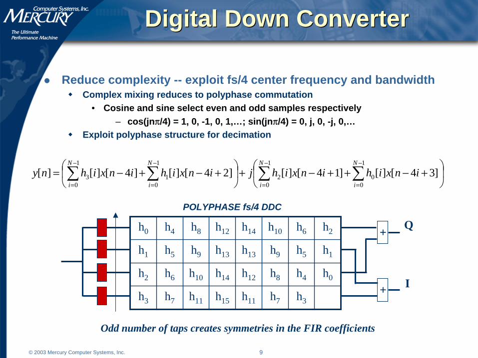
Digital Down ConverterDigital Down Converter
Reduce complexity -- exploit fs/4 center frequency and bandwidthComplex mixing reduces to polyphase commutation
• Cosine and sine select even and odd samples respectively– cos(jnπ/4) = 1, 0, -1, 0, 1,…; sin(jnπ/4) = 0, j, 0, -j, 0,…
Exploit polyphase structure for decimation
h3h7h11h15h11h7h3
h0h4h8h12h14h10h6h2
h1h5h9h13h13h9h5h1
h2h6h10h14h12h8h4h0 ++ I
Q
POLYPHASE fs/4 DDC
Odd number of taps creates symmetries in the FIR coefficients
⎟⎠
⎞⎜⎝
⎛ +−++−+⎟⎠
⎞⎜⎝
⎛ +−+−= ∑∑∑∑−
=
−
=
−
=
−
=
1
00
1
02
1
01
1
03 ]34[][]14[][]24[][]4[][][
N
i
N
i
N
i
N
i
inxihinxihjinxihinxihny
10© 2003 Mercury Computer Systems, Inc.
Digital Down ConverterDigital Down Converter
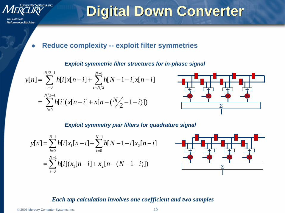
Reduce complexity -- exploit filter symmetries
+ + + +
Σ
+ + + +
Σ
)])12([][]([
][]1[][][][
12
0
12
0
1
2
iNnxinxih
inxiNhinxihny
N
i
N
i
N
Ni
−−−+−=
−−−+−=
∑
∑ ∑−
=
−
=
−
=
Exploit symmetric filter structures for in-phase signal
Exploit symmetry pair filters for quadrature signal
)])1([][]([
][]1[][][][
2
1
01
1
0
1
021
iNnxinxih
inxiNhinxihny
N
i
N
i
N
i
−−−+−=
−−−+−=
∑
∑ ∑−
=
−
=
−
=
Each tap calculation involves one coefficient and two samples
11© 2003 Mercury Computer Systems, Inc.
Digital Down ConverterDigital Down Converter
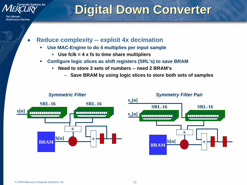
Reduce complexity -- exploit 4x decimationUse MAC-Engine to do 4 multiplies per input sample
• Use fclk = 4 x fs to time share multipliersConfigure logic slices as shift registers (SRL’s) to save BRAM
• Need to store 3 sets of numbers -- need 2 BRAM’s– Save BRAM by using logic slices to store both sets of samples
Symmetric Filter Symmetry Filter Pair
BRAM
SRL-16
+
SRL-16
h[n]
x[n]
+BRAM
SRL-16 SRL-16
h[n]
x2[n]
x1[n]
+
+

12© 2003 Mercury Computer Systems, Inc.
Low Pass FilterLow Pass Filter
Reduce complexity -- use MAC-Engine FIR implementationRun multipliers at 4x sample rate -- time share multipliersExploit constant length-decimation product
• Single structure handles multiple filter implementations• Single clock frequency
Use dual-bank feature of BRAM• First bank stores samples• Second bank stores FIR coefficients clk
outTapsEngMAC f
fNN =−
h[n]
x[n]
+
BRAM
h[n]
+
BRAM
+
MAC-Engine MAC-Engine

13© 2003 Mercury Computer Systems, Inc.
EqualizerEqualizer
Reduce complexity -- reduce number of multipliers and BRAM’sExploit fclk/fs -- use MAC-EngineImplement complex multiply using only 3 MAC-Engines
• Use common product term in complex multiply
)()( iririr
iirrr
hhxhxx
hxhxy
−+−=−=
rirrir
riiri
hxxhhx
hxhxy
)()( −−+=+=
hr
+xi
(hr- hi)
(hr+ hi)
xr+
+
+
+ yr
yi
+
+
+
+ yr
yi
xr
xi
+hi
hr+
+
Trade logic slices for multipliers Trade logic slices for block RAM
14© 2003 Mercury Computer Systems, Inc.
Front-End RealizationFront-End Realization
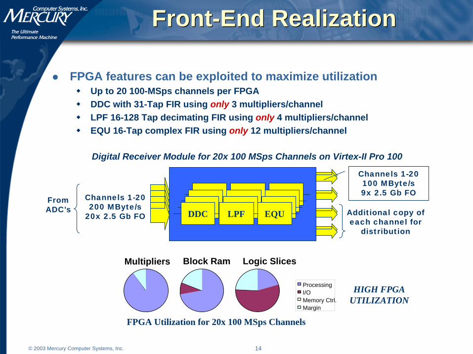
FPGA features can be exploited to maximize utilizationUp to 20 100-MSps channels per FPGADDC with 31-Tap FIR using only 3 multipliers/channelLPF 16-128 Tap decimating FIR using only 4 multipliers/channelEQU 16-Tap complex FIR using only 12 multipliers/channel
Channels 1-20200 MByte/s
20x 2.5 Gb FO
From ADC’s Additional copy of
each channel for distribution
Channels 1-20100 MByte/s9x 2.5 Gb FODDC EQULPF
DDC EQULPFDDC EQULPF
DDC EQULPF
Digital Receiver Module for 20x 100 MSps Channels on Virtex-II Pro 100
Multipliers Block Ram Logic Slices
ProcessingI/OMemory Ctrl.Margin
FPGA Utilization for 20x 100 MSps Channels
HIGH FPGAUTILIZATION
15© 2003 Mercury Computer Systems, Inc.
Back-End ProcessingBack-End Processing
FPGAs can be used to address data flow requirements that persist in the system until application of adaptive beamforming weights
Digital Pulse Compression• Fast convolution with FFT IP cores
Doppler Processing• FPGA FFT IP cores available
Adaptive Beamforming Weight Application• Similar advantages to those in sub-array beamformer
FPGAs can augment weight computationQR Decomposition
• New FPGA solutions may replace microprocessorsCholesky Decomposition
• Possibly form covariance matrix in adjunct FPGA

16© 2003 Mercury Computer Systems, Inc.
Digital Pulse CompressionDigital Pulse Compression
FFT IP cores can be used to implement pulse compression8192-tap FFT @ 25 MSps/channel6 sub-array channels / FPGA3-stage pipelined convolver -- 2 convolvers / FPGAEnough resources to sum partial products from beamformer
Memory
MULFFT IFFTSUM
Partial Product 1
Partial Product 2
Memory
MULFFT IFFTI/O
Multipliers Block Ram Logic Slices
Processing
I/O
Memory Ctrl.
Margin
DIGITAL PULSE COMPRESSION FPGA UTILIZATION
GOOD FPGAUTILIZATION
FFT cores tend to be BRAM hungry.
Doppler processing can be implemented using similar FFT cores
17© 2003 Mercury Computer Systems, Inc.
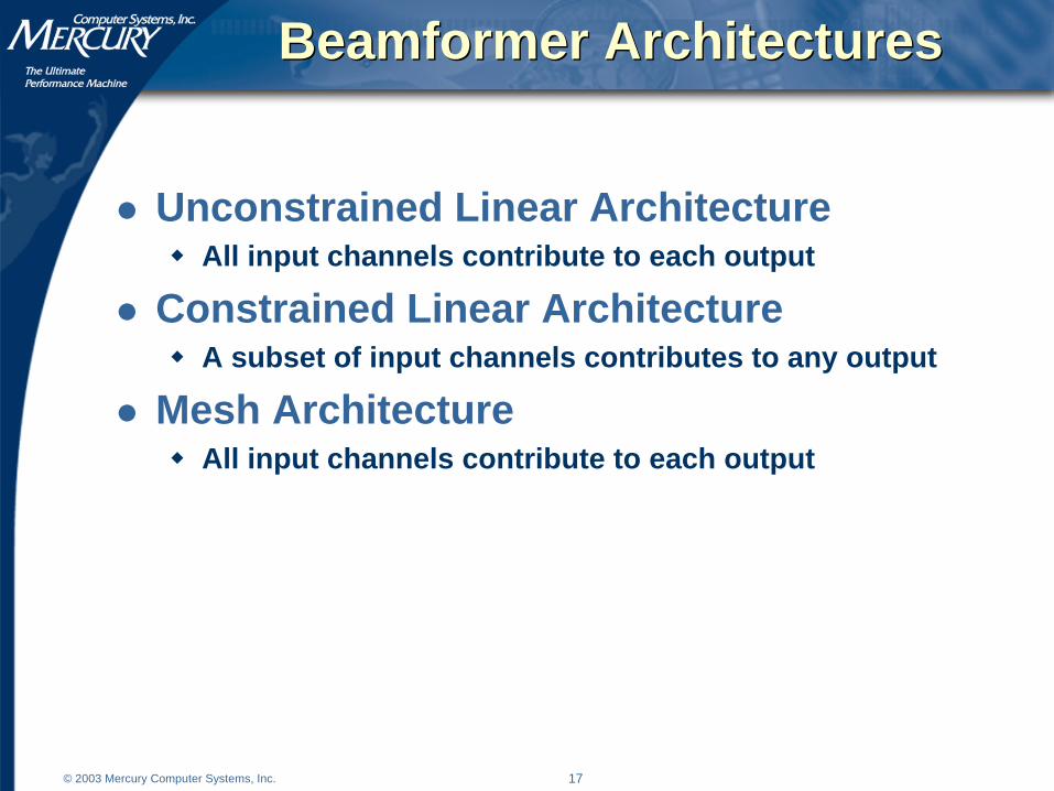
Beamformer ArchitecturesBeamformer Architectures
Unconstrained Linear ArchitectureAll input channels contribute to each output
Constrained Linear ArchitectureA subset of input channels contributes to any output
Mesh ArchitectureAll input channels contribute to each output

18© 2003 Mercury Computer Systems, Inc.
Beamformer Module ConstraintsBeamformer Module Constraints
Basic limits are imposed by I/O and number of multipliersInputs over 18-bits can increase the number of multipliers
Keep watch on bit growth in front-end processing
I/O and Multiplier Constraints for Virtex-II Pro 100
Assumes: 3-MAC / CMAC25 MSps channels100 MHz clock
1
10
100
1000
1 10 100
Number of Input Channels
Nu
mb
er o
f O
utp
ut
Ch
ann
els
Sample
clkAMACsPerFPGnelsOutputChanelInputChann R
fNNN
⋅≤
3
nelOutputChan
OutputLinksOutputLinknelsOutputChan R
RNN ≤
elInputChann
InputLinkInputLinkselsInputChann R
RNN ≤USEABLE
CONFIGURATIONS

19© 2003 Mercury Computer Systems, Inc.
Beamformer Module ConstraintsBeamformer Module Constraints
Multiplexing must be designed to maximize communicationBeam Partitioned output multiplexing may reduce efficiencyAlternate multiplexing methods may be necessary
810
1214
1618
2022
24
26
2830
3234
3638
40
0102030405060708090
100
0 10 20 30 40Number of Channels per Beam
Mu
ltip
lexi
ng
Eff
icie
ncy
⎟⎟⎠
⎞⎜⎜⎝
⎛⎥⎦
⎥⎢⎣
⎢⎥⎥
⎤⎢⎢
⎡−=
Link
nelOutputChanrBeamChannelsPeLinks
LinkLinksMUX R
RNN
RN1
1η
Data can also be partitioned by link: each link carried an integral number of channels
20© 2003 Mercury Computer Systems, Inc.
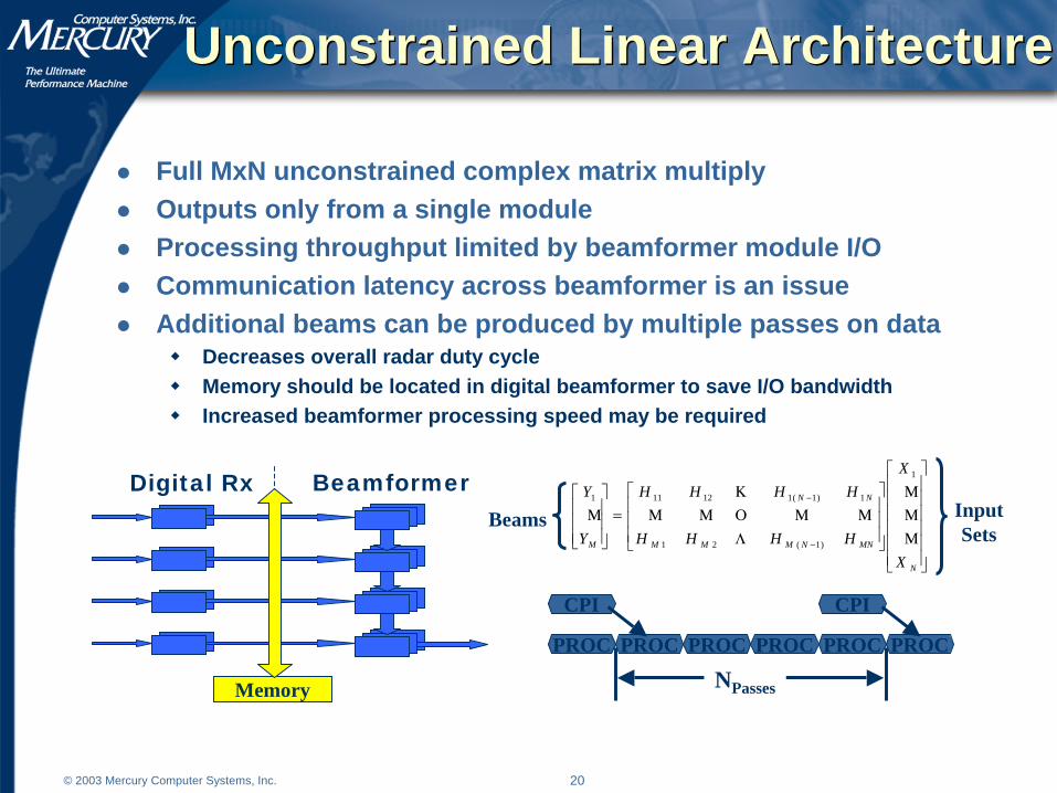
Unconstrained Linear ArchitectureUnconstrained Linear Architecture
Full MxN unconstrained complex matrix multiplyOutputs only from a single moduleProcessing throughput limited by beamformer module I/OCommunication latency across beamformer is an issueAdditional beams can be produced by multiple passes on data
Decreases overall radar duty cycleMemory should be located in digital beamformer to save I/O bandwidthIncreased beamformer processing speed may be required
Digital Rx Beamformer
Memory
PROC
NPasses
CPI
PROC PROC PROC PROC PROC
CPI
⎥⎥⎥⎥⎥⎥
⎦
⎤
⎢⎢⎢⎢⎢⎢
⎣
⎡
⎥⎥⎥
⎦
⎤
⎢⎢⎢
⎣
⎡
=⎥⎥⎥
⎦
⎤
⎢⎢⎢
⎣
⎡
−
−
N
MNNMMM
NN
M
X
X
HHHH
HHHH
Y
Y
ΜΜΜ
ΛΜΜΟΜΜ
ΚΜ
1
)1(21
1)1(112111
Beams InputSets

21© 2003 Mercury Computer Systems, Inc.
Unconstrained Linear ArchitectureUnconstrained Linear Architecture
Unconstrained linear beamformer module is I/O boundTotal number of input links plus output links is constantChoice of input to output balance affects utilization
1
10
100
1000
1 10 100
Number of Input Channels
Nu
mb
er o
f O
utp
ut
Ch
ann
els COMPUTATIONAL
LIMIT
COMMUNICATIONLIMIT
USEABLECONFIGURATIONS
4 input module
20 input module
Note:adding additional non-MGT connections could potentially increase throughput
22© 2003 Mercury Computer Systems, Inc.
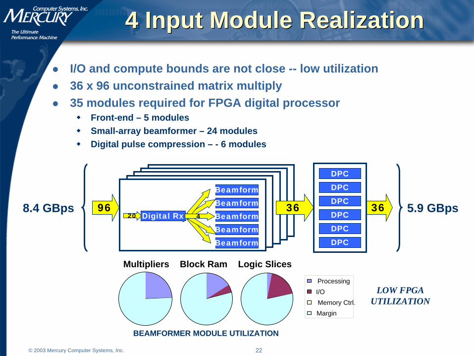
4 Input Module Realization4 Input Module Realization
I/O and compute bounds are not close -- low utilization36 x 96 unconstrained matrix multiply35 modules required for FPGA digital processor
Front-end – 5 modulesSmall-array beamformer – 24 modulesDigital pulse compression – - 6 modules
LOW FPGAUTILIZATION
BEAMFORMER MODULE UTILIZATION
Multipliers Block Ram Logic Slices
Processing
I/O
Memory Ctrl.
Margin
96BeamformBeamform
Beamform
Beamform
Beamform
Digital Rx20 436 368.4 GBps 5.9 GBps
DPCDPC
DPCDPC
DPC
DPC
23© 2003 Mercury Computer Systems, Inc.
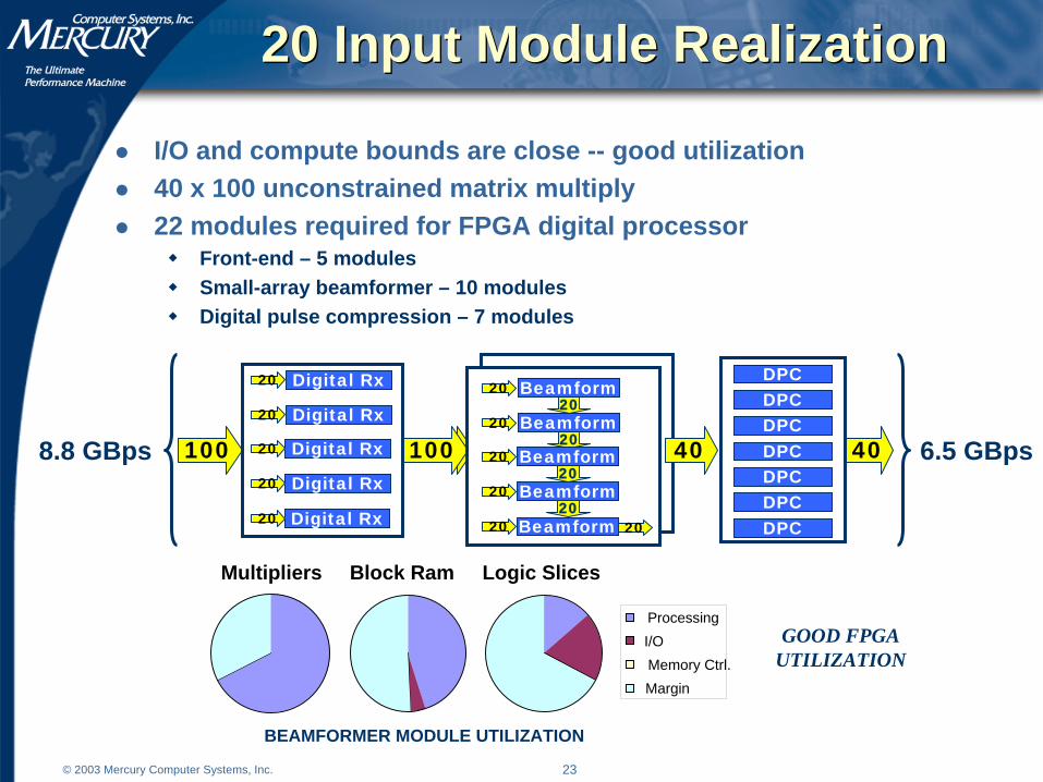
20 Input Module Realization20 Input Module Realization
I/O and compute bounds are close -- good utilization 40 x 100 unconstrained matrix multiply 22 modules required for FPGA digital processor
Front-end – 5 modulesSmall-array beamformer – 10 modulesDigital pulse compression – 7 modules
GOOD FPGAUTILIZATION
BEAMFORMER MODULE UTILIZATION
Multipliers Block Ram Logic Slices
Processing
I/O
Memory Ctrl.
Margin
6.5 GBps8.8 GBps 100 100 40
Digital Rx
Digital Rx
Digital Rx
Digital Rx
Digital Rx
20
20
20
20
20
Beamform2020
Beamform2020
Beamform2020
Beamform2020
Beamform20 20
40
DPCDPCDPCDPCDPCDPCDPC
24© 2003 Mercury Computer Systems, Inc.
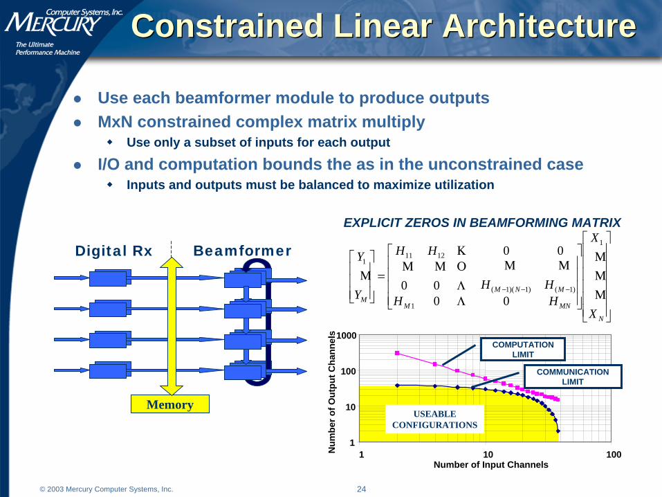
Constrained Linear ArchitectureConstrained Linear Architecture
Use each beamformer module to produce outputsMxN constrained complex matrix multiply
Use only a subset of inputs for each output
I/O and computation bounds the as in the unconstrained caseInputs and outputs must be balanced to maximize utilization
⎥⎥⎥⎥⎥⎥
⎦
⎤
⎢⎢⎢⎢⎢⎢
⎣
⎡
⎥⎥⎥⎥
⎦
⎤
⎢⎢⎢⎢
⎣
⎡
=⎥⎥⎥
⎦
⎤
⎢⎢⎢
⎣
⎡
−−−
N
MNM
MNMM
X
X
HHHH
HH
Y
Y
ΜΜΜ
Λ
ΜΜΛΟΜΜΚ
Μ
1
1
)1()1)(1(
12111
0000
00Digital Rx Beamformer
Memory
1
10
100
1000
1 10 100Number of Input Channels
Nu
mb
er o
f Ou
tpu
t C
han
nels
COMPUTATIONLIMIT
COMMUNICATIONLIMIT
USEABLECONFIGURATIONS
EXPLICIT ZEROS IN BEAMFORMING MATRIX
25© 2003 Mercury Computer Systems, Inc.
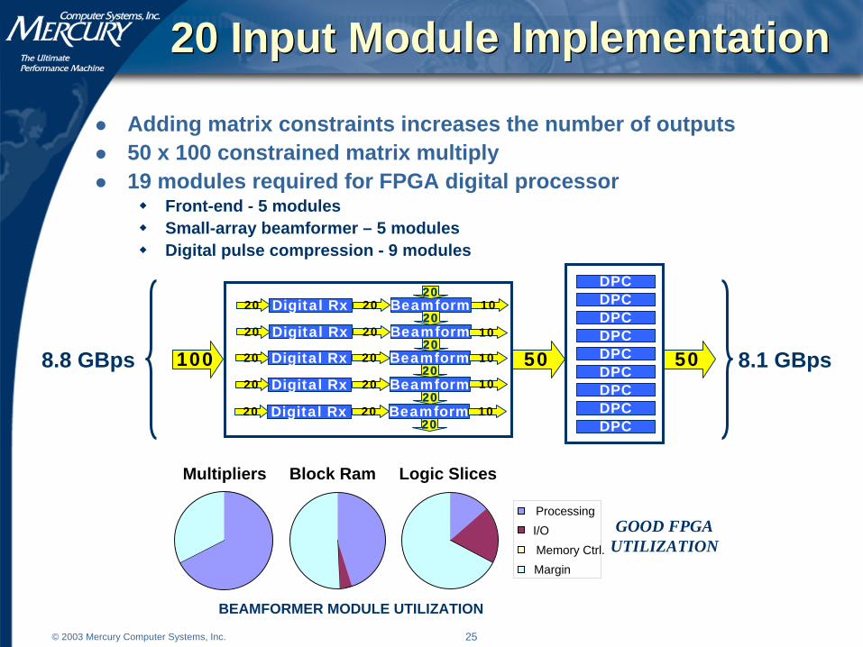
20 Input Module Implementation20 Input Module Implementation
Adding matrix constraints increases the number of outputs50 x 100 constrained matrix multiply19 modules required for FPGA digital processor
Front-end - 5 modulesSmall-array beamformer – 5 modulesDigital pulse compression - 9 modules
GOOD FPGAUTILIZATION
BEAMFORMER MODULE UTILIZATION
Multipliers Block Ram Logic Slices
Processing
I/O
Memory Ctrl.
Margin
100 50
BeamformDigital Rx20 2020
BeamformDigital Rx20 2020
BeamformDigital Rx20 2020
BeamformDigital Rx20 2020
BeamformDigital Rx20 2020
10
20
10
10
10
10
508.8 GBps 8.1 GBpsDPCDPCDPC
DPCDPC
DPC
DPC
DPCDPC

26© 2003 Mercury Computer Systems, Inc.
Mesh ArchitectureMesh Architecture
Mesh architecture offers utilization enhancementI/O and computation bounds touch
Full unconstrained matrix multiplyPartially formed beams sent forward for summing in DPC
⎥⎥⎥⎥⎥⎥
⎦
⎤
⎢⎢⎢⎢⎢⎢
⎣
⎡
⎥⎥⎥
⎦
⎤
⎢⎢⎢
⎣
⎡
=⎥⎥⎥
⎦
⎤
⎢⎢⎢
⎣
⎡
−
−
N
MNNMMM
NN
M
X
X
HHHH
HHHH
Y
Y
ΜΜΜ
ΛΜΜΟΜΜ
ΚΜ
1
)1(21
1)1(112111
5 links12 channels
5 links12 channels
5 links10 channels
5 links10 channels
5 links10 channels
5 links10 channels
5 links12 channels
5 links12 channels
40 x 48 CMAC using 4 modules
NO EXPLICIT ZEROS IN BEAMFORMING MATRIX
1
10
100
1000
1 10 100Number of Input Channels
Nu
mb
er o
f O
utp
ut
Ch
ann
els
COMMUNICATIONLIMITS
COMPUTATIONLIMIT
USEABLECONFIGURATIONS
Note: Computation limit normalized for architecture

27© 2003 Mercury Computer Systems, Inc.
Mesh ImplementationMesh Implementation
I/O and compute bounds touch -- high utilization 40 x 96 unconstrained matrix multiply20 modules required for FPGA digital processor
Front-end – 5 modulesSmall-array beamformer – 8 modulesDigital pulse compression – 7 modules
HIGH FPGAUTILIZATION
BEAMFORMER MODULE UTILIZATION
Multipliers Block Ram Logic Slices
ProcessingI/OMemory Ctrl.Margin
8.4 GBps 6.5 GBps96 40
Digital RxDigital RxDigital Rx
Digital RxDigital Rx
96BeamformBeamformBeamformBeamform
40
DPCDPCDPCDPCDPCDPCDPC
28© 2003 Mercury Computer Systems, Inc.
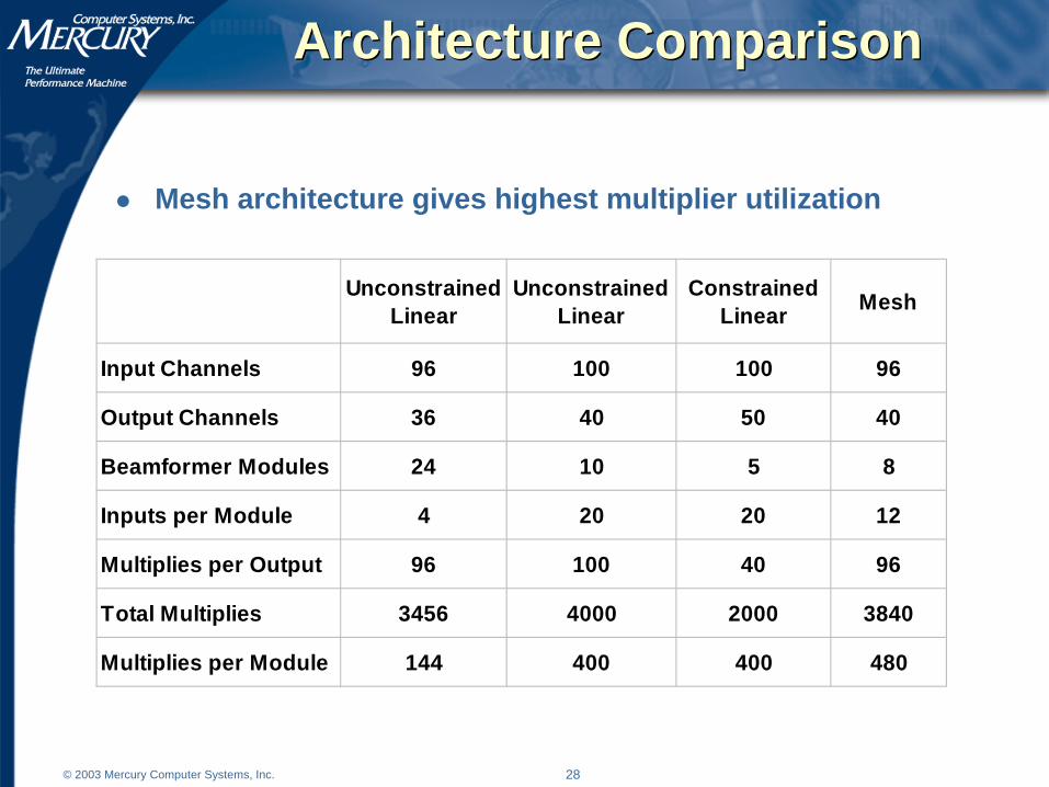
Architecture ComparisonArchitecture Comparison
Mesh architecture gives highest multiplier utilization
UnconstrainedLinear
UnconstrainedLinear
ConstrainedLinear
Mesh
Input Channels 96 100 100 96
Output Channels 36 40 50 40
Beamformer Modules 24 10 5 8
Inputs per Module 4 20 20 12
Multiplies per Output 96 100 40 96
Total Multiplies 3456 4000 2000 3840
Multiplies per Module 144 400 400 480

29© 2003 Mercury Computer Systems, Inc.
Large SystemsLarge Systems
Large systems can be created through layering beamformers8 beam system, 20 channels per beam -- 160 channels160 x 96 unconstrained matrix multiply
65 modules required for FPGA digital processorFront-end - 5 modulesSmall-array beamformer – 32 modulesDigital pulse compression - 28 modules
Channels 1-96 Channels 1-160
30© 2003 Mercury Computer Systems, Inc.
SummarySummary
FPGAs can provide efficient I/O and computational power to address high input bandwidths of modern radar systems.
Front-end processingSub-array beamformerDigital pulse compressionAdaptive beamforming
System topologies that provide efficient utilization of computational and I/O resources change dramatically as system requirements scale.
Watch I/O and computation bounds
Small changes in system requirements can dramatically increase complexity of FPGA implementations when computational bounds of embedded resources is exceeded.
Watch for symmetries in filtersWatch bit growth before 18-bit multipliers
FPGAs should be used until application of adaptive beamforming weights due to high bandwidth dataflow.