Beam Element - iut.ac.ir · We conclude that the stiffness matrix for the simple beam element is...
36
Beam Element By S. Ziaei Rad
Transcript of Beam Element - iut.ac.ir · We conclude that the stiffness matrix for the simple beam element is...

Beam Element
ByS. Ziaei Rad

Simple Plane Beam Element

Simple Plane Beam Element
Elementary Beam Theory:

Direct Stiffness Method
L
1z 2z
1v 2v
1 2L
1F 2F
1M2M
L
21k
41k11k
31k
12
L22k
42k
12k32k
12
11 z
L23k 43k
13k 33k1 2
34k
L24k
44k
14k1
212 z
ab
c d

Direct Stiffness Method
12
3
1 @12
213
111
EILk
EILknodev
0 2
1 @02
212
111
EILk
EILknodez
0 0 )( 3111 kkForcey
0 0)( 1141212 LkkkMoment
node
Similar relations can be written for b, c and d cases to obtainthe four columns of the stiffness matrix.

Element stiffness equation
Element stiffness equation (local node: i, j or 1, 2):
(*)
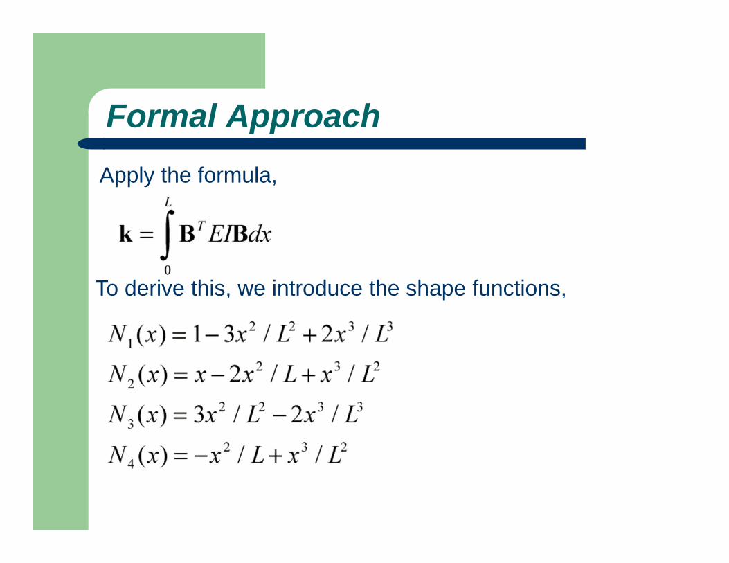
Formal ApproachApply the formula,
To derive this, we introduce the shape functions,

Formal ApproachThen, we can represent the deflection as,
which is a cubic function. Notice that,
which implies that the rigid body motion is represented by the assumed deformed shape of the beam.
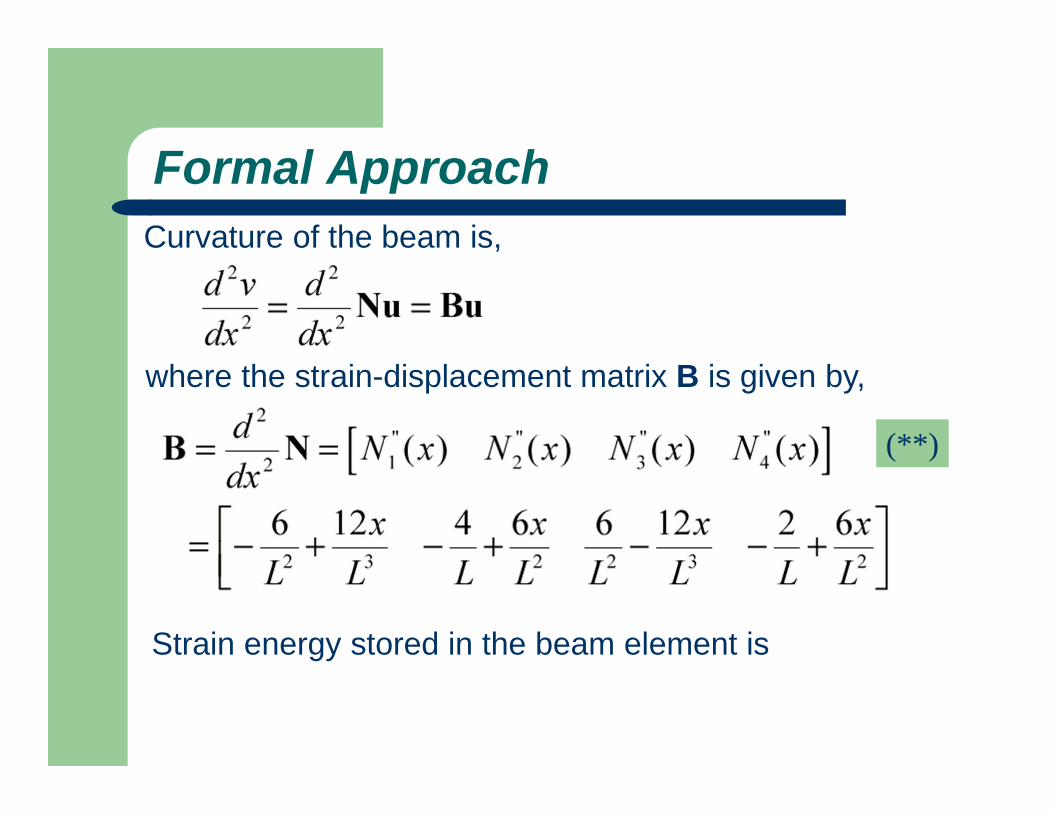
Formal ApproachCurvature of the beam is,
where the strain-displacement matrix B is given by,
Strain energy stored in the beam element is
(**)

Formal Approach

Formal ApproachWe conclude that the stiffness matrix for the simple beamelement is
Applying the result in (**) and carrying out the integration, wearrive at the same stiffness matrix as given in (*).
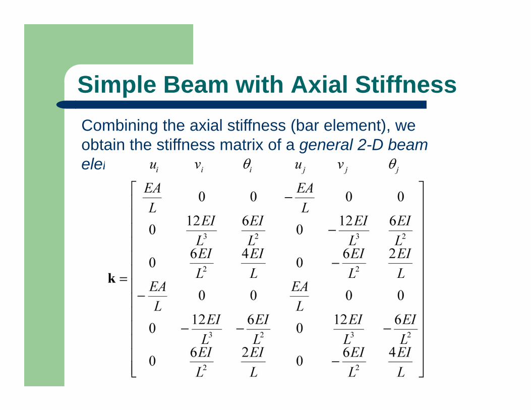
Simple Beam with Axial StiffnessCombining the axial stiffness (bar element), we obtain the stiffness matrix of a general 2-D beam element,

Example 2.5
Problem: The beam shown above is clamped at the two ends andacted upon by the force P and moment M in the mid-span.Find the deflection and rotation at the center node and the reaction forces and moments at the two ends.

Example 2.5Solution: Element stiffness matrices are,

Example 2.5Global FE equation is,

Example 2.5Loads and constraints (BC’s) are,
Reduced FE equation,
Solving this we obtain,

Example 2.5From global FE equation, we obtain the reaction forces andmoments,
Stresses in the beam at the two ends can be calculated using the formula,

Simple Beam TheoryNote that the FE solution is exact according to the simple beamtheory, since no distributed load is present between the nodes.Recall that,
and
Thus,
If q(x)=0, then exact solution for the deflection v is a cubicfunction of x, which is what described by our shape functions.

Equivalent Nodal Loads of Distributed Transverse Load
=
This can be verified by considering the work done by thedistributed load q.
Do this as an exercise !!!

Example 2.6Problem: A cantilever beam with distributed lateral load p asshown above.
Find the deflection and rotation at the right end, thereaction force and moment at the left end.

Example 2.6
The work-equivalent nodal loads are shown below,
where

Example 2.6Applying the FE equation, we have
Load and constraints (BC’s) are,
Reduced equation is,

Example 2.6Solving this, we obtain,
These nodal values are the same as the exact solution.Note that the deflection v(x) (for 0 < x< L) in the beam by theFEM is, however, different from that by the exact solution. Theexact solution by the simple beam theory is a 4th orderpolynomial of x, while the FE solution of v is only a 3rd orderpolynomial of x.
(+)

Example 2.6If the equivalent moment m is ignored, we have,
The errors in (++) will decrease if more elements are used. Theequivalent moment m is often ignored in the FEM applications.The FE solutions still converge as more elements are applied.
From the FE equation, we can calculate the reaction forceand moment as, where the result in (+) is used.
(++)

Example 2.6This force vector gives the total effective nodal forces which include the equivalent nodal forces for the distributed lateral load p given by,
The correct reaction forces can be obtained as follows,
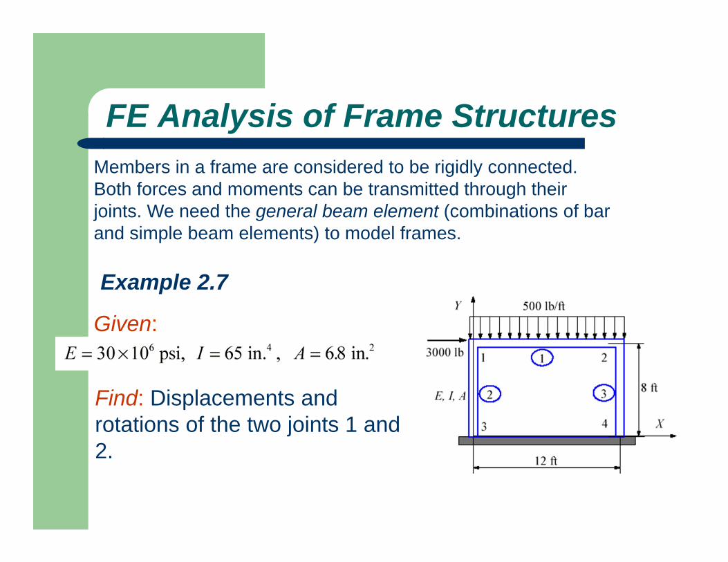
FE Analysis of Frame StructuresMembers in a frame are considered to be rigidly connected.Both forces and moments can be transmitted through theirjoints. We need the general beam element (combinations of barand simple beam elements) to model frames.
Example 2.7
Given:
Find: Displacements and rotations of the two joints 1 and 2.

Example 2.7Solution: For this example, we first convert the distributed load to its equivalent nodal loads.

Example 2.7In local coordinate system, the stiffness matrix for a general
2-D beam element is:

Example 2.7
For element 1 we have

Example 2.7For elements 2 and 3, we have the stiffness matrix in local system,

Example 2.7where i=3, j=1 for element 2 and i=4, j=2 for element 3.
In general, the transformation matrix T is,
We have l = 0, m = 1 for both elements 2 and 3. Thus,

Example 2.7
Using the transformation relation,we obtain the stiffness matrices in the global coordinate system for elements 2 and 3,

Example 2.7
and

Example 2.7
Assembling the global FE equation and noticing the following boundary conditions,
we obtain the condensed FE equation,

Example 2.7
Solving this, we get
To calculate the reaction forces and moments at the two ends,we employ the element FE equations for element 2 and element 3. We obtain,

Results CheckDraw the free-body diagram of the frame. Equilibrium is maintained with the calculated forces and moments.