Beam and detectorsThese detectors are electronic detectors: when a particle interacts with the...
20
Beam and detectors Beamline for Schools 2019 Note If you have participated in BL4S in the past, you may have read earlier versions of this document. Please note that in 2019 the BL4S experiments will take place at DESY, Hamburg, Germany. The conditions of the beam at DESY are different from what CERN was offering until 2018. Please read this document carefully to understand if your experiment is feasible under the conditions available at DESY.
Transcript of Beam and detectorsThese detectors are electronic detectors: when a particle interacts with the...

Beam and detectors
Beamline for Schools 2019
Note
If you have participated in BL4S in the past, you may have read earlier versions of
this document. Please note that in 2019 the BL4S experiments will take place at
DESY, Hamburg, Germany. The conditions of the beam at DESY are different from
what CERN was offering until 2018. Please read this document carefully to
understand if your experiment is feasible under the conditions available at DESY.

Preface
All the big discoveries in science have started by curious minds asking simple ques-
tions: How? Why? This is how you should start. Then you should investigate with
the help of this document whether your question could be answered with the avail-
able equipment (or with material that you can provide) and the experimental setup of
Beamline for Schools at DESY. As your proposal takes shape, you will be learning
a lot about particle physics, detectors, data acquisition, data analysis, statistics and
much more. You will not be alone during this journey: there is a list of volunteer physi-
cists who are happy to interact with you and to provide you with additional information
and advice.
Remember: It is not necessary to propose a very ambitious experiment to
succeed in the Beamline for Schools competition. We are looking for exciting
and original ideas!
2
Contents
Introduction 4
The Beamline for Schools . . . . . . . . . . . . . . . . . . . . . . . . . . . 4
Typical equipment . . . . . . . . . . . . . . . . . . . . . . . . . . . . . . . . 4
Trigger and readout . . . . . . . . . . . . . . . . . . . . . . . . . . . . . . . 5
The Beam Lines 6
Beam production . . . . . . . . . . . . . . . . . . . . . . . . . . . . . . . . 6
Bending magnets . . . . . . . . . . . . . . . . . . . . . . . . . . . . . . . . 7
Collimator . . . . . . . . . . . . . . . . . . . . . . . . . . . . . . . . . . . . 7
Beam composition . . . . . . . . . . . . . . . . . . . . . . . . . . . . . . . 8
The DESY test beam areas . . . . . . . . . . . . . . . . . . . . . . . . . . . 9
The BL4S detectors 10
Scintillation counter . . . . . . . . . . . . . . . . . . . . . . . . . . . . . . . 10
Delay Wire Chamber (DWC) / Tracking chamber . . . . . . . . . . . . . . . 10
MicroMegas detectors / Tracking chamber . . . . . . . . . . . . . . . . . . . 11
Beam telescope . . . . . . . . . . . . . . . . . . . . . . . . . . . . . . . . . 11
Multi Gap Resistive Plate Chamber (MRPC) . . . . . . . . . . . . . . . . . 12
Timepix detector . . . . . . . . . . . . . . . . . . . . . . . . . . . . . . . . 13
Lead crystal calorimeter . . . . . . . . . . . . . . . . . . . . . . . . . . . . 14
Halo counter . . . . . . . . . . . . . . . . . . . . . . . . . . . . . . . . . . . 15
Additional Equipment 16
BRM dipole magnet and PCMAG solenoid . . . . . . . . . . . . . . . . . . 16
Other infrastructure . . . . . . . . . . . . . . . . . . . . . . . . . . . . . . . 16
Data Acquisition 17
Glossary 18
3
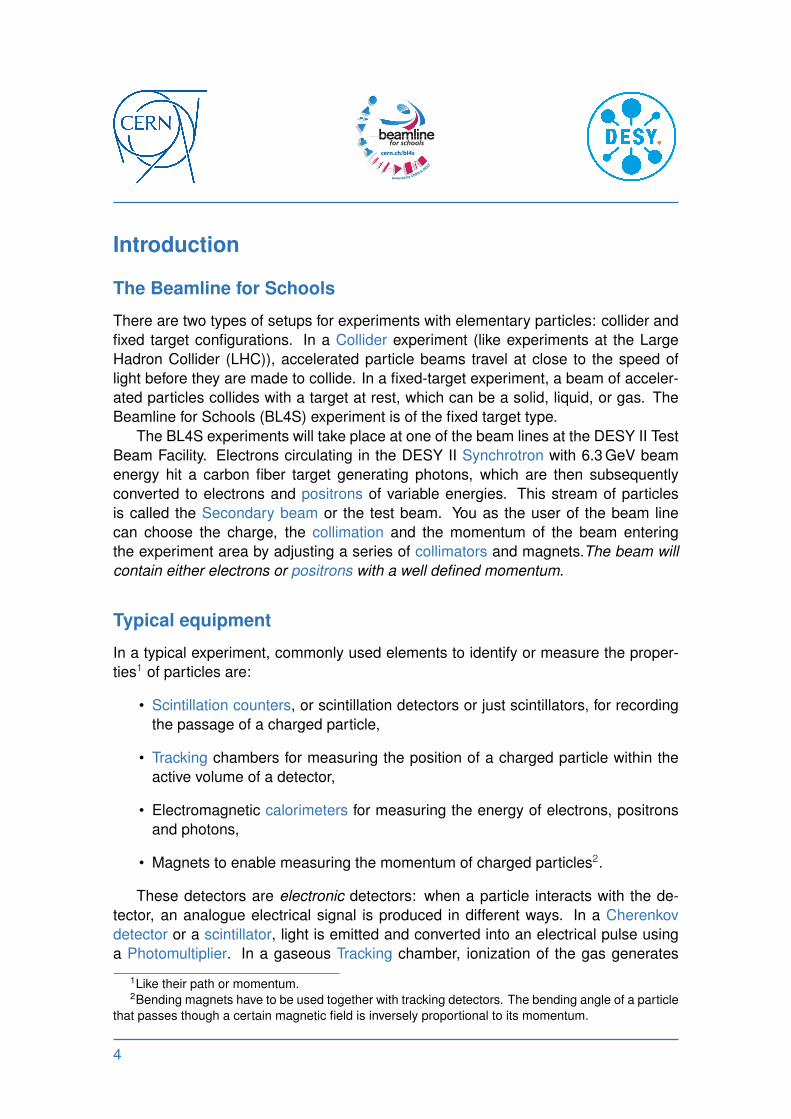
Introduction
The Beamline for Schools
There are two types of setups for experiments with elementary particles: collider and
fixed target configurations. In a Collider experiment (like experiments at the Large
Hadron Collider (LHC)), accelerated particle beams travel at close to the speed of
light before they are made to collide. In a fixed-target experiment, a beam of acceler-
ated particles collides with a target at rest, which can be a solid, liquid, or gas. The
Beamline for Schools (BL4S) experiment is of the fixed target type.
The BL4S experiments will take place at one of the beam lines at the DESY II Test
Beam Facility. Electrons circulating in the DESY II Synchrotron with 6.3 GeV beam
energy hit a carbon fiber target generating photons, which are then subsequently
converted to electrons and positrons of variable energies. This stream of particles
is called the Secondary beam or the test beam. You as the user of the beam line
can choose the charge, the collimation and the momentum of the beam entering
the experiment area by adjusting a series of collimators and magnets.The beam will
contain either electrons or positrons with a well defined momentum.
Typical equipment
In a typical experiment, commonly used elements to identify or measure the proper-
ties1 of particles are:
• Scintillation counters, or scintillation detectors or just scintillators, for recording
the passage of a charged particle,
• Tracking chambers for measuring the position of a charged particle within the
active volume of a detector,
• Electromagnetic calorimeters for measuring the energy of electrons, positrons
and photons,
• Magnets to enable measuring the momentum of charged particles2.
These detectors are electronic detectors: when a particle interacts with the de-
tector, an analogue electrical signal is produced in different ways. In a Cherenkov
detector or a scintillator, light is emitted and converted into an electrical pulse using
a Photomultiplier. In a gaseous Tracking chamber, ionization of the gas generates
1Like their path or momentum.2Bending magnets have to be used together with tracking detectors. The bending angle of a particle
that passes though a certain magnetic field is inversely proportional to its momentum.
4
electrons that are multiplied in electric fields. The typical duration of the signals is
100 ns and the signal voltages are typically 100 mV to 1 V. The signals are sent to a
readout system where they are digitized and eventually read out by a computer and
stored to a hard disk. In solid-state detectors like silicon sensors, the particle gener-
ates electron / hole pairs along its trajectory. The generated charge is usually on the
level of 20 000 electrons or less and is collected at the edge of the sensor. The signal
is then digitized close to the sensor and readout by a computer.
Examples of detectors in the BL4S experiment are described in more detail in
the following chapters. It should be emphasized that experiments can be conducted
without making use of all of these detectors.
Trigger and readout
Signals from some of the detectors are used to build the Trigger. The trigger logic
identifies interesting interactions (“events”) and instructs the computer to initiate the
readout of the data from all the detectors. The trigger is a fundamental and complex
component of LHC experiments, where collision rates are very high and only a very
small fraction of the collisions are of interest3. In BL4S, the trigger is much simpler
and might, for example, require coincident signals from two or more scintillators along
the beam path to indicate the passage of a particle. When a trigger occurs, data from
all detectors are recorded by the readout system and a signal is sent to a computer
that transfers the data to mass storage, usually a disk. This mechanism is very similar
to when you take a picture with a digital camera. When the shutter-release button is
pressed, data (light) is transferred to the charge coupled device (CCD) and recorded
to memory. One difference is that in the case of BL4S, the exposure time is about
100 ns.
A large amount of software has been developed at CERN and elsewhere for the
analysis of experimental data. The analysis software is based on a framework called
Root, which is used by many physics laboratories all over the world.
3For example, the production of a Higgs Boson occurs in one out of a trillion events (where one
trillion is 1012).
5
The Beam Lines
Beam production
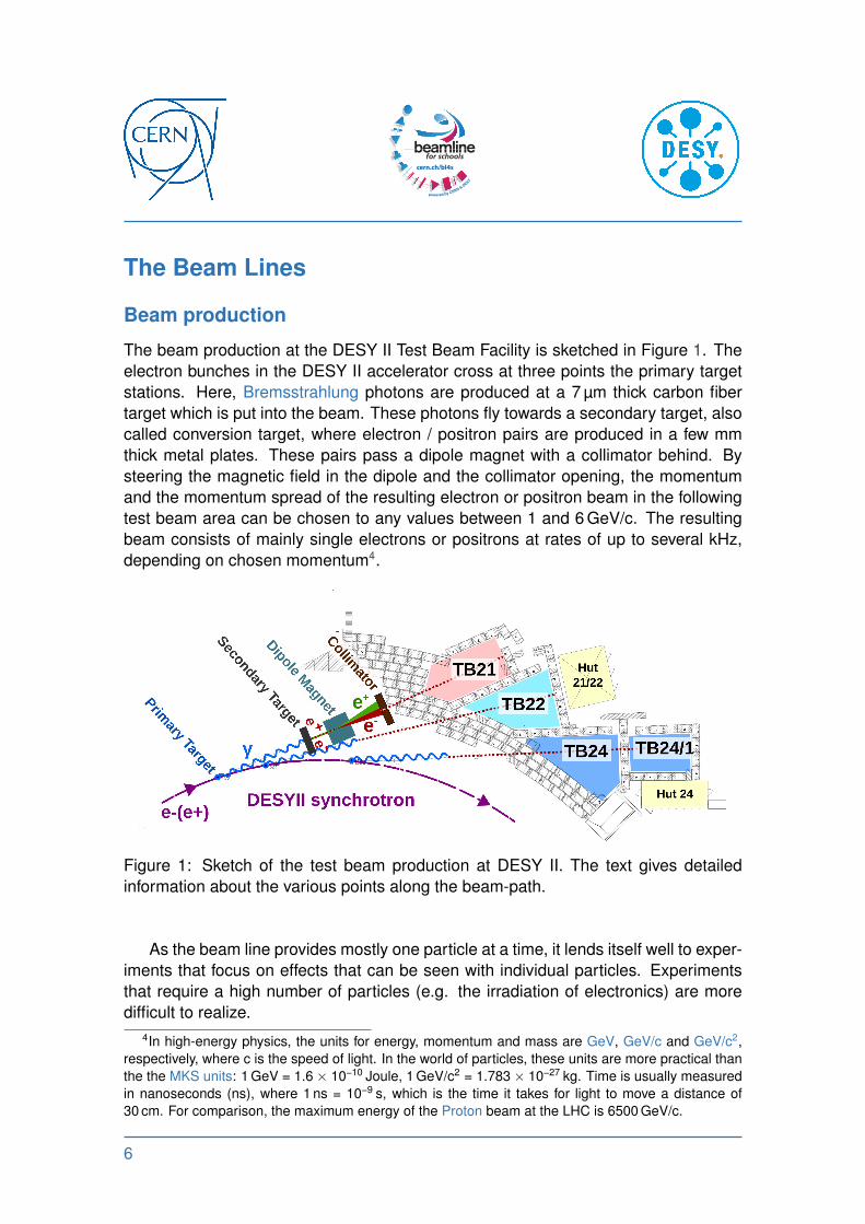
The beam production at the DESY II Test Beam Facility is sketched in Figure 1. The
electron bunches in the DESY II accelerator cross at three points the primary target
stations. Here, Bremsstrahlung photons are produced at a 7 µm thick carbon fiber
target which is put into the beam. These photons fly towards a secondary target, also
called conversion target, where electron / positron pairs are produced in a few mm
thick metal plates. These pairs pass a dipole magnet with a collimator behind. By
steering the magnetic field in the dipole and the collimator opening, the momentum
and the momentum spread of the resulting electron or positron beam in the following
test beam area can be chosen to any values between 1 and 6 GeV/c. The resulting
beam consists of mainly single electrons or positrons at rates of up to several kHz,
depending on chosen momentum4.
Figure 1: Sketch of the test beam production at DESY II. The text gives detailed
information about the various points along the beam-path.
As the beam line provides mostly one particle at a time, it lends itself well to exper-
iments that focus on effects that can be seen with individual particles. Experiments
that require a high number of particles (e.g. the irradiation of electronics) are more
difficult to realize.
4In high-energy physics, the units for energy, momentum and mass are GeV, GeV/c and GeV/c2,
respectively, where c is the speed of light. In the world of particles, these units are more practical than
the the MKS units: 1 GeV = 1.6 × 10⁻¹⁰ Joule, 1 GeV/c2 = 1.783 × 10⁻²⁷ kg. Time is usually measured
in nanoseconds (ns), where 1 ns = 10−9 s, which is the time it takes for light to move a distance of
30 cm. For comparison, the maximum energy of the Proton beam at the LHC is 6500 GeV/c.
6
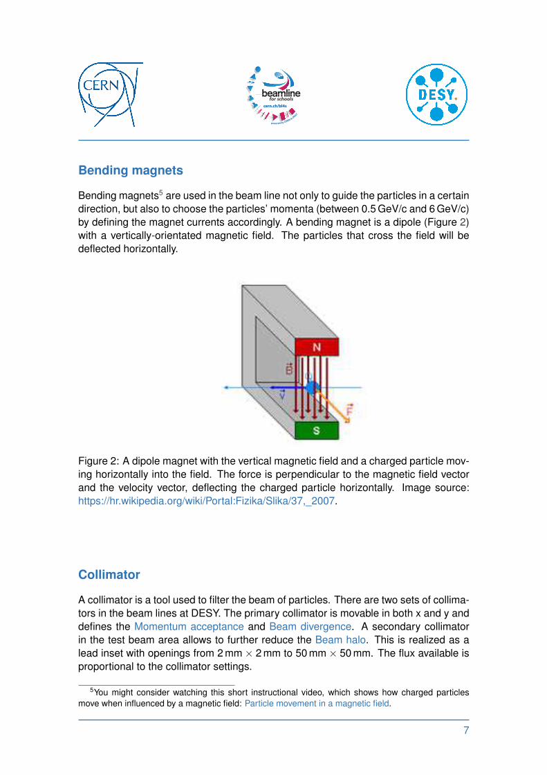
Bending magnets
Bending magnets5 are used in the beam line not only to guide the particles in a certain
direction, but also to choose the particles’ momenta (between 0.5 GeV/c and 6 GeV/c)
by defining the magnet currents accordingly. A bending magnet is a dipole (Figure 2)
with a vertically-orientated magnetic field. The particles that cross the field will be
deflected horizontally.
Figure 2: A dipole magnet with the vertical magnetic field and a charged particle mov-
ing horizontally into the field. The force is perpendicular to the magnetic field vector
and the velocity vector, deflecting the charged particle horizontally. Image source:
https://hr.wikipedia.org/wiki/Portal:Fizika/Slika/37,_2007.
Collimator
A collimator is a tool used to filter the beam of particles. There are two sets of collima-
tors in the beam lines at DESY. The primary collimator is movable in both x and y and
defines the Momentum acceptance and Beam divergence. A secondary collimator
in the test beam area allows to further reduce the Beam halo. This is realized as a
lead inset with openings from 2 mm × 2 mm to 50 mm × 50 mm. The flux available is
proportional to the collimator settings.
5You might consider watching this short instructional video, which shows how charged particles
move when influenced by a magnetic field: Particle movement in a magnetic field.
7

Beam composition
The amount of particles in the beam depends on the selected momentum, the Col-
limator opening and the polarity. The particle rate can reach up to 10 kHz. Figure 3
shows the typical dependence of the particle rate on the selected particle momentum.
For example, ff you select a beam momentum of 1 GeV/c, the relative particle rate is
approximately 0.5. Therefore the beamline will deliver 5000 particles per second when
the beam is on. The negative (positive) beam contains negatively (positively) charged
electrons (positrons). It is not possible to have a beam of photons. The particles of
test beam are relativistic. This means they are moving at almost the speed of light.
0 1 2 3 4 5 6
particle momentum [GeV/c]
0.0
0.2
0.4
0.6
0.8
1.0
par
ticl
era
te[a
.u.]
TB21
0
1
2
3
4
par
ticl
efl
ux
[kH
z/cm
2]
Figure 3: Typical dependence of the beam rate on the selected momentum; in this
example measured in area TB21. The rates is normalized to a maximum of 1.0.
The beam provided by DESY II is pulsed due to the DESY II cycle of 80 ms6. There
is one pulse every 80 ms. The duration of a pulse depends on the selected particle
momentum and varies between 20 and 40 ms.
The beam has a more or less round cross section. The beam spot size is driven by
the collimators and has a typical dimension of 2 cm × 2 cm when entering the beam
area. The further away the beam is from the entrance window, the wider it gets.
The amount of background particles (photons, muons, neutrons) generated in ad-
dition to the electrons and positrons is negligible. The beam at DESY can be consid-
ered a pure electron / positron beam.
6A period in which DESY II ramps from 450 MeV to 6.3 GeV and back to 450 MeV again.
8

The DESY test beam areas
The Beamline for Schools takes place in one of the test beams areas, which have a
size of about 5 m × 10 m, where the available equipment which can be laid out ac-
cording to the needs of your experiment. Also, depending on the area, there are
some fixed installations like two big magnets and beam telescopes (detailed descrip-
tions below). Additionally, it may be possible to install devices that are brought by
your team to the experimental area7. Each request will be reviewed individually and
will need to respect health and safety guidelines. For example, the installation of large
amounts of combustible material (e.g. wood) is not possible for safety reasons. It is
also not possible to expose any Biological material to the beam.
7Please note that CERN and DESY cannot guarantee the installation of all the suggested devices.
9

The BL4S detectors
Scintillation counter
A scintillator is a material that produces scintillation light, a property of luminescence,
when excited by ionizing radiation8. Luminescent materials, when struck by an incom-
ing charged particle, absorb some of the particle’s energy and scintillate, i.e. re-emit,
the absorbed energy in the form of light. A scintillation counter is obtained when a
scintillator slab is connected to an electronic light sensor, in our case a sensitive Pho-
tomultiplier tube. Photomultiplier tubes absorb the light emitted by the scintillator and
re-emit it in the form of electrons, via the photoelectric effect. The subsequent mul-
tiplication of these photoelectrons results in an amplified, electrical pulse that can be
analyzed; yielding meaningful information about the particle that originally struck the
scintillator.
Two scintillators are part of the fixed setup of the beam line. Several additional
scintillators are available for installation in the experiment. The scintillators can be
used for counting particles or for setting up the trigger logic. Fast scintillators can be
used for timing the particles (i.e. measuring the time it takes for a particle to travel
from one scintillator to another).
Delay Wire Chamber (DWC) / Tracking chamber
The Delay Wire Chamber (DWC) is a multi-wire chamber that can give the coordinates
of the position of a particle that passed through the detector. It uses an array of wires
at high voltage connected to a delay line. The chamber is filled with gas (a mixture of
argon and CO2). Any Ionizing particle that passes through the chamber will ionize the
atoms of the gas. The resulting ions and electrons are accelerated by an electric field
across the chamber, causing a localized cascade of ionization. The signal from the
wires builds up two electric waves in the delay line, one in each direction. By using
a reference signal as a common start and measuring the time delays for the waves
to reach each end of the delay line, the impact point —where the first ionizing took
place— can be determined.
The active area is 10 cm × 10 cm and position resolutions of 200 µm–300 µm can
be achieved. The unit “µm” represents a micrometer, one millionth of a meter. How-
ever, the chamber can measure only one particle inside a certain time window of
approximately 100 ns. Three DWCs are available for the experiment, if required.
8You can watch a simple animation here:
https://upload.wikimedia.org/wikipedia/commons/2/22/Scintillation_Detector.gif .
10

MicroMegas detectors / Tracking chamber
MicroMegas detectors serve the same purpose as DWCs; they allow you to track
particles. They are “better” than the DWCs because they have a larger surface and a
higher resolution. The disadvantage is that they are not as fast. With the electronics
that will be used to read those out, we can at most track 500 particles per second. The
MicroMegas detectors have a spatial resolution of about 200 µm and an active area
of 40 cm × 40 cm. They are 1D detectors and therefore able to record the position of
a charged particle in the vertical or the horizontal plane. As there are four of them,
you can build, by combining two of them, two 2D detectors. The MicroMegas, for
example, can be used behind the BRM (see below) to record the angle by which
charged particles are deflected in the magnetic field. You may also be able to use
them in order to measure the scattering of particles in a target that you install in the
beam line.
Figure 4: MicroMegas detector.
Beam telescope
A beam telescope can measure the track of a particle with high precision. Knowing
the track of a particle allows pointing to the source of the beam —thus, it is historically
called telescope as the telescopes used in astronomy. The resolution achievable by a
telescope are usually in the order of a few µm.
A beam telescope consists of at least three planes which are subsequently or-
dered along the beam axis. Each plane has a sensitive silicon pixel chip similar to
nowadays camera chips in mobile phones. If a high energetic charged particle will go
through the chip it will deposit a small amount of energy which is amplified in the sen-
sor and results in a signal in the corresponding pixel cell. Knowing the positions in the
11
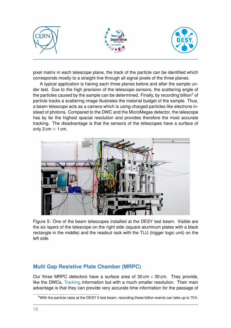
pixel matrix in each telescope plane, the track of the particle can be identified which
corresponds mostly to a straight line through all signal pixels of the three planes.
A typical application is having each three planes before and after the sample un-
der test. Due to the high precision of the telescope sensors, the scattering angle of
the particles caused by the sample can be determined. Finally, by recording billion9 of
particle tracks a scattering image illustrates the material budget of the sample. Thus,
a beam telescope acts as a camera which is using charged particles like electrons in-
stead of photons. Compared to the DWC and the MicroMegas detector, the telescope
has by far the highest spacial resolution and provides therefore the most accurate
tracking. The disadvantage is that the sensors of the telescopes have a surface of
only 2 cm × 1 cm.
Figure 5: One of the beam telescopes installed at the DESY test beam. Visible are
the six layers of the telescope on the right side (square aluminum plates with a black
rectangle in the middle) and the readout rack with the TLU (trigger logic unit) on the
left side.
Multi Gap Resistive Plate Chamber (MRPC)
Our three MRPC detectors have a surface area of 30 cm × 30 cm. They provide,
like the DWCs, Tracking information but with a much smaller resolution. Their main
advantage is that they can provide very accurate time information for the passage of
9With the particle rates at the DESY II test beam, recording these billion events can take up to 70 h.
12

a particle. In a well-calibrated system, values as low as 100 ps10 can be reached.
Therefore, the MRPCs are very useful detectors for time-of-flight measurements.
The MRPC consists of a stack of resistive plates, where spacers between these
plates define a series of gas gaps. Anode and cathode electrodes are placed on
the outer surfaces of the outermost resistive plate while all interior plates are left
electrically floating. The resistive plates are transparent to the fast signals generated
by the avalanches inside each gas gap. The induced signal on the external electrodes
is the sum of the activities of all the gaps. You can use the MRPCs to check if the
electrons or positions are really traveling at the speed of light.
Timepix detector
The Timepix chip is designed as a universal readout chip for various types of radiation.
It can be used in combination with a pixelated semiconductor detector with a gaseous
Time Projection Chamber (TPC) or without any sensor (electro-statically collecting
electrons)11.
(a) (b)
Figure 6: The timepix Pixel detector:
a) This device consists of two chips connected by the bump-bonding technique. The upper
chip is a pixelated semiconductor detector (usually silicon), the bottom one an ASIC readout.
b) Sample ToA data from Timepix, Top left: gamma photons (dots), Top right: beta particles
(squiggles), Bottom left: mixed field of gammas (dots) and alphas (blobs).
The available device consists of a semiconductor detector chip bump-bonded to
the readout chip. The detector chip is equipped with a single common backside elec-
trode and a front side matrix of electrodes (256 × 256 square pixels with a pitch of
55 µm).
10Where ps stands for pico second, one trillionth of a second.11See also these videos: Medipix 2 - See Through Science and Material resolving CT using Timepix
13

Each Timepix pixel can work in one of three modes:
1. Medipix mode — The counter counts the incoming particles.
2. Timepix mode or ToA (Time of arrival mode) — The counter works as a timer,
measuring time of the particle detection. This mode distinguishes between par-
ticles and / or reconstructs tracks of particles.
3. Time over threshold (TOT) mode — Measurement of the amount of deposited
charge in each pixel.
The chip can deliver up to 1000 frames per second. Usually, this kind of device is
used for particle Tracking.
Lead crystal calorimeter
A lead crystal Calorimeter is a detector that measures the energy of impinging par-
ticles (therefore it is not a Tracking detector). An electron hitting the calorimeter will
produce a fully contained Rlectromagnetic shower, depositing all its energy in the
calorimeter and thus allowing a very precise measurement of its energy. By measur-
ing the deposited energy, the energy of the incoming particle can be measured. The
16 available calorimeters each have a volume of 10 cm × 10 cm × 37 cm (Figure 7).
Figure 7: Stack of lead crystal calorimeters.
14

Halo counter
The halo counter is a set of 4 scintillators that form a hole around the beam passage
(Figure 8) or a single scintillator with a hole. Its purpose is to identify particles that
are too far away from the beam axis. While a collimator immediately filters the beam
by rejecting particles with a larger angle, the halo counter identifies them and thus
makes it possible to choose to either reject or flag them. This is useful, e.g. for flag-
ging particles that interacted with a certain absorber and underwent scattering. The
opening of the BL4S halo counter can be adjusted between 1 cm and 15 cm.
Figure 8: A Halo counter.
15
Additional Equipment
BRM dipole magnet and PCMAG solenoid
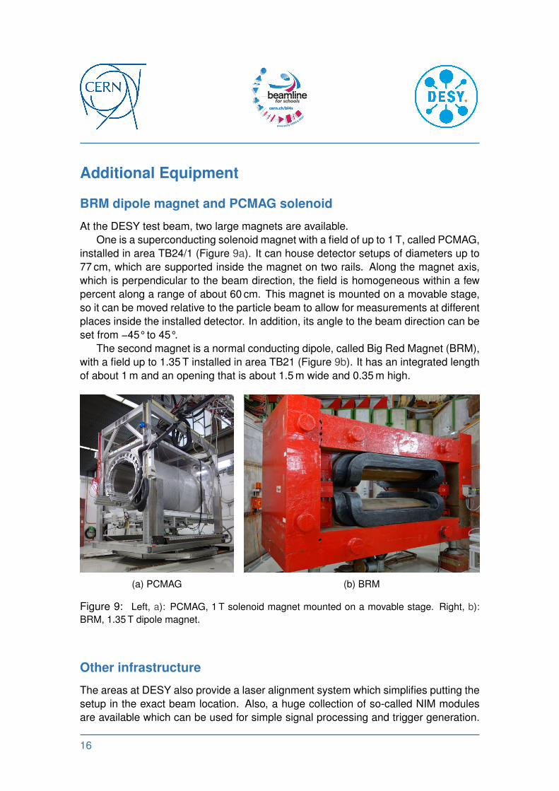
At the DESY test beam, two large magnets are available.
One is a superconducting solenoid magnet with a field of up to 1 T, called PCMAG,
installed in area TB24/1 (Figure 9a). It can house detector setups of diameters up to
77 cm, which are supported inside the magnet on two rails. Along the magnet axis,
which is perpendicular to the beam direction, the field is homogeneous within a few
percent along a range of about 60 cm. This magnet is mounted on a movable stage,
so it can be moved relative to the particle beam to allow for measurements at different
places inside the installed detector. In addition, its angle to the beam direction can be
set from −45°to 45°.
The second magnet is a normal conducting dipole, called Big Red Magnet (BRM),
with a field up to 1.35 T installed in area TB21 (Figure 9b). It has an integrated length
of about 1 m and an opening that is about 1.5 m wide and 0.35 m high.
(a) PCMAG (b) BRM
Figure 9: Left, a): PCMAG, 1 T solenoid magnet mounted on a movable stage. Right, b):
BRM, 1.35 T dipole magnet.
Other infrastructure
The areas at DESY also provide a laser alignment system which simplifies putting the
setup in the exact beam location. Also, a huge collection of so-called NIM modules
are available which can be used for simple signal processing and trigger generation.
16
Additional electronic modules for the read-out of the detectors as well as associated
software will be provided by CERN. We do not expect you to design the read-out
system of your experiment. This will be done by experts of DESY and CERN for the
winning proposals.
Data Acquisition
BL4S will provide a complete data acquisition system for reading out the detectors and
controlling the experiment. This system is fast enough to trace up to 2000 particles
per second.
The data acquisition system provides tools for the on-line monitoring of the exper-
iment in the form of histograms.
Don’t worry about the details of this system. Experts of CERN and DESY will help
the winners of BL4S to set-up the system and will also provide code for and assistance
with the analysis of your data.
17
Glossary
Beam divergence The widening of the beam along its path. 7
Beam halo The cloud of particles surrounding the main
beam in an accelerator. 7
Biological material Living cells, human / animal tissue. 9
Boson Particles can be categorized as bosons or
fermions according to their intrinsic spin. 5
Bremsstrahlung An electromagnetic radiation produced by the
deceleration of a charged particle when de-
flected by another charged particle. See also:
Wikipedia:Bremsstrahlung. 6
Calorimeter A detector that measures the energy of a par-
ticle. 4, 14
Cherenkov detector A gas volume that emits light when it gets pen-
etrated by charged particles. The light emis-
sion depends on the type of particle and its
momentum. Wikipedia: Cherenkov detector. 4
Collider An accelerator that collides two beams which
are cruising in opposite directions as in the
LHC. 4
Collimator A device to limit spatial width of the beam per-
pendicular to its direction of flight. See also:
Wikipedia: Collimator. 4, 8
GeV, Electronvolt A unit of energy used in particle physics 6
GeV/c A unit of momentum used in particle physics. 6
GeV/c2 A unit of mass used in particle physics. 6
Ionizing particle A particle with enough energy to knock out
electrons of atoms or molecules. 10
18
MicroMegas Micro-MEsh Gaseous Structure, a particle de-
tector amplifying ionization signals in a gas vol-
ume. See also: Wikipedia: MicroMegas. 11
MKS units Units expressed in meters, kilograms and sec-
onds. 6
Momentum acceptance Particles with this range of momentum will
pass through. 7
Muon, µ A particle like an electron but much heavier and
not stable (decays into other particles). 8
Photomultiplier A device that converts photons into electric sig-
nals. 4, 10
Pixel detector A tracking detector with a 2-dimensional array
of sensors; usually made from silicon. 13
Positron, e+ An elementary particle that is the antimatter
twin of the negatively charged electron; this
means both have the same properties, but the
positron is positively charged. 4
Proton A proton is a subatomic particle, with a positive
electric charge. 6
Rlectromagnetic shower An avalanche of particles created from the in-
teraction of a high-energetic particle with the
material of a calorimeter. 14
Root A powerful software framework for the display
and analysis of physics data. 5
Scintillation counter A transparent material that emits light when
penetrated by charged particles. 4, 10, 15
Secondary beam Particles created from the interaction of the pri-
mary beam with a target. 4
Synchrotron A specific type of particle accelerator, in which
the particles are accelerated and fly along a cir-
cular path. See also: Wikipedia: Synchrotron.
4
19
Tracking The measurement of the trajectory of a parti-
cle. 4, 12, 14
Trigger It identifies interesting interactions (“events”)
and instructs the computer to initiate the read-
out of the data from all the detectors. 5
20