B.E. PROJECT REPORT ON VISION BASED ... a g e 1 B.E. PROJECT REPORT ON VISION BASED AUTONOMOUS ROBOT...
88
Page 1 B.E. PROJECT REPORT ON VISION BASED AUTONOMOUS ROBOT NAVIGATION Submitted in Partial fulfilment of the requirements for the award of the Degree of Bachelor of Engineering (B.E.) in Manufacturing Processes and Automation Engineering Submitted By Ankit Kulshreshtha (615/MP/11) Prachi Sharma (304/CO/11) Priyanshi Gupta (310/CO/11) Guided By Dr. Sachin Maheshwari, Professor, MPAED, NSIT Dr. Anand Gupta, Professor, COED, NSIT Department of Manufacturing Processes and Automation Engineering Netaji Subhas Institute of Technology University of Delhi 2015
Transcript of B.E. PROJECT REPORT ON VISION BASED ... a g e 1 B.E. PROJECT REPORT ON VISION BASED AUTONOMOUS ROBOT...
P a g e 1
B.E. PROJECT REPORT
ON
VISION BASED AUTONOMOUS ROBOT NAVIGATION
Submitted in Partial fulfilment of the requirements for the award of the
Degree of Bachelor of Engineering (B.E.) in
Manufacturing Processes and Automation Engineering
Submitted By
Ankit Kulshreshtha (615/MP/11)
Prachi Sharma (304/CO/11)
Priyanshi Gupta (310/CO/11)
Guided By
Dr. Sachin Maheshwari, Professor, MPAED, NSIT
Dr. Anand Gupta, Professor, COED, NSIT
Department of Manufacturing Processes and Automation Engineering
Netaji Subhas Institute of Technology
University of Delhi
2015
P a g e 2
CERTIFICATE
This is to certify that the dissertation entitled “VISION BASED AUTONOMOUS
ROBOT NAVIGATION” being submitted by Ankit Kulshreshtha, Prachi Sharma
and Priyanshi Gupta in the Department of Manufacturing Processes and
Automation Engineering, Netaji Subhas Institute of Technology, Delhi, for the
award of the degree of “Bachelor of Engineering” is a bona fide record of the
work carried out by them. They have worked under my guidance and
supervision and have fulfilled the requirements for the submission of this report,
which has reached the requisite standard.
The results contained in this report have not been submitted in part or in full, to
any university or institute for the award of any degree of diploma.
Dr. Sachin Maheshwari
Professor and Head of Department
Manufacturing Processes and Automation Engineering Department
NSIT
P a g e 3
CERTIFICATE
This is to certify that the dissertation entitled “VISION BASED AUTONOMOUS
ROBOT NAVIGATION” being submitted by Ankit Kulshreshtha, Prachi Sharma
and Priyanshi Gupta in the Department of Manufacturing Processes and
Automation Engineering, Netaji Subhas Institute of Technology, Delhi, for the
award of the degree of “Bachelor of Engineering” is a bona fide record of the
work carried out by them. They have worked under my guidance and
supervision and have fulfilled the requirements for the submission of this report,
which has reached the requisite standard.
The results contained in this report have not been submitted in part or in full, to
any university or institute for the award of any degree of diploma.
Dr. Anand Gupta
Professor
Computer Engineering Department
NSIT

P a g e 4
Candidate’s Declaration
This is to certify that the work which is being hereby presented by us in this
project titled "VISION BASED AUTONOMOUS ROBOT NAVIGATION" in Partial
fulfillment of the award of the Bachelor of Engineering submitted at the
Department of Manufacturing Processes and Automation Engineering , Netaji
Subhas Institute of Technology Delhi, is a genuine account of our work carried
out during the period from January 2015 to May 2015 under the guidance of
Prof. Sachin Maheshwari, Head of Department(MPAE) and Prof. Anand Gupta
(COE), Netaji Subhas Institute of Technology Delhi.
The matter embodied in the project report to the best of our knowledge has not
been submitted for the award of any other degree elsewhere.
Dated:
Ankit Kulshreshtha
Prachi Sharma
Priyanshi Gupta
This is to certify that the above declaration by the students is true to the best of
my knowledge.
Prof. Sachin Maheshwari Prof. Anand Gupta

P a g e 5
Acknowledgement
Any Project indisputably plays one of the most important roles in an engineering
student‘s life to make him a successful engineer. It provides the students with an
opportunity to gain valuable experience on the practical application of their
technical knowledge and also brings out and hones their technical creativity.
Thus, the need for one is indispensable.
We would like to express our deep gratitude towards our mentor Dr. Sachin
Maheshwari, Professor, Manufacturing Processes and Automation Dept,
Netaji Subhas Institute of Technology, New Delhi under whose supervision
we completed our work. His invaluable suggestions, enlightening comments and
constructive criticism always kept our spirits up during our work. The effective
deadlines and the art of tackling project problems he provided us with, is
invaluable.
Our experience in working together has been wonderful. We hope that the
knowledge, practical and theoretical, that we have gained through this term B.E.
Project will help us in our future endeavors in the field.
We express our gratitude to Dr. Anand Gupta, for his constant support and
motivation, without which the project would have been an impossible task.
ANKIT KULSHRESHTHA PRACHI SHARMA PRIYANSHI GUPTA
P a g e 6
Table of Contents
i. CERTIFICATE 2
ii. CERTIFICATE 3
iii. Candidate’s Declaration 4
iv. Acknowledgement 5
v. Table of Contents 6
vi. List of Figures 8
vii. List of Tables 10
viii. ABSTRACT 11
1 INTRODUCTION 12
MOBILE ROBOT NAVIGATION USING VISION SENSORS 14
IMAGE-BASED NAVIGATION: AN OVERVIEW 16
MOTIVATION 19
PROBLEM IDENTIFICATION 21
CONTRIBUTION 21
REPORT STRUCTURE 22
2 LITERATURE SURVEY 23
COMPUTER VISION 23
2.1.1 Computer vision system methods 24
2.1.2 Graphical Processing 27
OPENCV 30
2.2.1 OpenCV Modules 31
Morphological operations 33

P a g e 7
2.3.1 Erosion and dilation 36
RASPBERRY PI 44
3 METHODOLOGY 51
Main Technologies of the Project 52
Materials Used In This Project 54
3.3 FRAMEWORK A 58
3.3.1 Setting up the Raspberry Pi 2 58
3.3.2 THE CAMERA 59
3.3.3 System Communication 60
3.3.4 Horizontal and Vertical motion control of the system 62
3.3.5 Setting up the Project 64
3.4 FRAMEWORK B 65
3.4.1 Identify the object: Obstacle/Destination 65
3.4.2 Simulating the Motor Driver Control (L298H) 70
3.4.3 Backtracking Algorithm[6] 72
4 Experiments and Results 74
5 CONCLUSION 79
6 FUTURE WORKS 80
7 REFERENCES 81
APPENDIX A- TOOLS AND PLATFORMS USED 83
Python 83
Ubuntu 84
APPENDIX B- CODE 85

P a g e 8
List of Figures
Figure 1 Probing of an image with a structuring element 33
Figure 2 Examples of simple structuring elements. 34
Figure 3 Fitting and hitting of a binary image with structuring elements s1 and
s2. 35
Figure 4 Grayscale image 36
Figure 5 Binary image by thresholding 36
Figure 6 Erosion: a 2×2 square structuring element 36
Figure 7 Erosion: a 3×3 square structuring element 37
Figure 8 Binary image 38
Figure 9 Dilation: a 3×3 square structuring element 39
Figure 10 Set operations on binary images 40
Figure 11 Binary image 41
Figure 12 Opening: a 2×2 square structuring element 41
Figure 13 Binary image f 41
Figure 14 f s (5×5 square) 41
Figure 15 f s (9×9 square) 41
Figure 16 Binary image 42
Figure 17 Closing: a 2×2 square structuring element 42
Figure 18 Closing with a 3×3 square structuring element 43
Figure 19 Arduino Uno 44
Figure 20 Raspberry Pi 46
Figure 21 BeagleBone Black 48
Figure 22 Main Technologies in this project 52
Figure 23 Workflow of the Project 54
Figure 24 Raspberry Pi 2 55
Figure 25 Wireless adapter 56
Figure 26 Logitech C270 HD Webcam 56
Figure 27 Castor Wheel 56
Figure 28 6V DC Motors 56
Figure 29 L298H Motor Driver 57
Figure 30 16000mAh Power Bank 57
Figure 31 Framework A 58
Figure 32 System Communication 60
Figure 33 Assembled Robot Front View 64
Figure 34 Assembled Robot Top View 64
Figure 35 Framework B 65
P a g e 9
Figure 36 Steps of Computer Vision System 65
Figure 37 Circuit Diagram of L298H Motor Driver 70
Figure 38 Raspberry Pi Putty Login Screen 75
Figure 39 Xming Connection 75
Figure 40 Raspbian Desktop on Xming 76
Figure 41 move.py Code working 77
Figure 42 Green Colour Detection on the robot 77

P a g e 10
List of Tables
Table 1 Motor A Truth Table ..................................................................................................... 70
Table 2 Motor B Truth Table ..................................................................................................... 71
P a g e 11
ABSTRACT
With the advancement of robotics technology and vast improvement of portable
computational devices and comparatively low cost and power-consumption,
mobile robots today have tremendous use and applications in various fields.
Vision-based robot navigation systems allow a robot to explore and to navigate
in its environment in a way that facilitates path planning and goal-oriented tasks.
The vision sensor is mainly used for obstacle detection and avoidance, object
detection and tracking, and interaction with users. We have proposed an
artificially intelligent technique of backtracking to be employed for autonomous
robot navigation in an unfamiliar arena using vision sensing.
We have chosen vision based autonomous robot navigation system for the
following uses in mind. It is only a few of the possibilities:
Autonomous robot navigation in a natural disastrous zone such as
inaccessible collapsed building areas in an event of earthquake to find
possible victims as a helping hand to rescue team.
Mobilizing visually or physically impaired or disabled persons
autonomously in a electronic wheel chair.
Mars Rover is using vision based navigation system.
As a service-bot, courier or delivery robot, etc.
P a g e 12
1 INTRODUCTION
The field of robotics has engendered great interest among researchers across
various fields in the recent past. The idea of employing a robot to perform a
specific task instead of a human has been fascinating. Robotics encompasses a
broad spectrum of technologies in which computational intelligence is embedded
into physical machines, creating systems with capabilities far exceeding the
individual basic components. Such robotic systems can carry out tasks that are
unachievable by conventional machines, or even by humans working with
conventional tools.
Robotic systems can be employed for a variety of tasks ranging from performing
medical surgery to the task of assembling a car or to the task of traversing in an
urban environment. One principle ability that one aspires of such systems to
perform the above tasks is to move by themselves, that is, ‘autonomously’.
Mobile robots are machines that move autonomously, either on the ground or in
the air/space or underwater. Such vehicles are generally unmanned, in the sense
that no humans are on board. The machines move by themselves, with sensors
and computational resources on-board to guide their motion.
The primary application of such robotic vehicles is their capability of traveling
where people cannot go, or where the hazards of human presence are great. For
P a g e 13
instance, to reach the surface of Mars, a spacecraft must travel more than a year,
and on arrival the surface has no air, water, or resources to support human life.
Hence robotic exploration is a fundamental step that provides enormous
scientific and technological rewards enhancing the knowledge of other planets.
The Mars rover is a specific example of a robotic vehicle capable of local
autonomous operation for segments of motion and defined scientific tasks.
Another example of a hostile and hazardous environment where robotic vehicles
are essential tools of work and exploration is the undersea world. Human divers
may dive to a hundred meters or more, but pressure, light, currents and other
factors limit such human exploration of the vast volume of the earth’s oceans.
Apart from the above, these vehicles are also employed in routine tasks that
occur over spaces and environments where machine mobility can effectively
replace direct human presence. For example, in large scale cultivation of crops,
underground mining etc. Finally applications of robotic vehicles also includes the
support of personal assistance (rehabilitation), in household tasks, and in
entertainment. For example, a wheelchair that utilizes emerging robotic
technologies for providing mobility to the handicapped.
Mobile Robot Navigation[4] is known as the ability of a robot to act based on its
knowledge and sensor values in order to reach its goal positions as efficiently
and as reliably as possible. At the first instance, it may seem a seemingly trivial
task to navigate a robot as compared to the task of brain surgery or automobile
manufacturing. However the latter tasks are carefully cut out and formed such
that they are largely a high-precision positioning application for a very

P a g e 14
specialized tool. Whereas in the former case, the problem is that there is no high
precision around, no available databases about what are the objects in the world
and the floor plan. Further, the environment may be unknown (with obstacles),
there may be people moving around, apart from presence of deformable objects
such as plants, toys etc. Dealing with such a variable environment poses a
plethora of challenges to a mobile system.
MOBILE ROBOT NAVIGATION USING VISION SENSORS
One of the main obstacles that have hindered the penetration of mobile robots
into wide consumer markets is the unavailability of powerful, versatile and
cheap sensing. Vision technology is potentially a clear winner as far as the ratio
of information provided versus cost is considered. Cameras of acceptable
accuracy are currently sold at a price which is one to two orders of magnitude
less than laser and sonar scanners. Vision is an attractive sensor as it helps in the
design of economically viable systems with simpler sensor limitations. Vision
potentially offers more portable and cost effective solutions, as new mass market
for camera technology has resulted in significantly reduced price and increased
performance. Moreover it can provide information unavailable to other sensors:
for instance, it provides semantic information of a scene through the
understanding of its visual appearance and not just the geometrical information
about it.

P a g e 15
The current trend in robot navigation is to try and use vision instead of more
traditional range sensors. Vision based robotic systems have gained popularity
recently, and several approaches have been proposed in the recent past. These
systems analyse the images of the scene taken by the camera attached to the
robot and use the visual cues to plan their action. The systems employ either
regular cameras (single or multiple) or omnidirectional vision sensors for
viewing the environment. The major distinguishing factor amongst the
approaches is the method in perceiving the scene and the way of extracting the
features from the scene. Much attention is being devoted to solve the non-trivial
problems implied by using visual information for navigating an agent through
the environment.
Unstructured and dynamic environments pose a crucial challenge to many real-
world applications. With non-vision sensors, it is impossible to predict and
model every possibility. As a result the parameters of the robot system were
earlier tuned in order to work properly in the new environment. However with
the emergence of cameras, such environments can be tackled more efficiently.
Traditionally, it has been assumed that the position of the target and/or the
robot was known (or at least partially known). However, the direct outputs of
vision sensors are generally not position information, but image features, which
may be distorted due to projection, and restricted by the field of view. In order to
obtain the global position and orientation of one object or even just to determine
their relative pose, various algorithms of calibration and transformation are
P a g e 16
required. Hence, all of the proposed approaches formulate the vision-based
navigation problem as a two-step process: first, to transfer the sensor features
back to pose information, and then make a motion plan in the pose space.
However, the transfer from sensor space to pose space is redundant and
introduces unnecessary uncertainty into the loop. It would be more beneficial to
directly use the sensory information and navigate the mobile robot. It is this
aspect, which is the focus of the thesis. More specifically, this thesis deals with
the problem of using off-the-shelf cameras fixed on inexpensive mobile
platforms, to enable navigation and control to given goal configurations directly
in the sensor space.
IMAGE-BASED NAVIGATION: AN OVERVIEW
A mobile robot that navigates in a large scale environment needs to know its
position in the world in order to successfully plan its path and its movements.
This requires establishing a close relation between the perceived environment
and the commands sent to the low-level controller, which necessitates complex
spatial reasoning relying on some kind of internal environment representation.
The general approach[5][3][1] to this problem is to provide the robot with a
detailed description of the environment (usually a geometrical map) obtained
using a stereo/monocular vision sensor mounted on the robot. Unfortunately,
extracting geometric information of the environment from the camera is time-
consuming and intolerant of noise. Few authors have successfully addressed this
solution using very robust uncertainty management systems, while few have
circumvented it by efficient management of the environment. Unfortunately,

P a g e 17
either of the above paradigms are not always feasible. There are situations in
which an exact map of the environment is either unavailable or useless: for
example, in old or unexplored buildings or in environments in which the
configuration of objects in the space changes frequently. Therefore, it would be
beneficial for the robot to build its own representations of the world.
The philosophy of memory-based reasoning offers an interesting perspective. In
the field of artificial intelligence research, memory-based reasoning has been
studied for a long time, which has been originally motivated from the human
reasoning process. In addition to the capability of reasoning about the
environment topology and geometry, humans show a capability for recalling
memorized scenes that help themselves to navigate. This implies that humans
have a sort of visual memory that can help them locate themselves in a large
environment. From these considerations, a new approach to the navigation and
localization problem has been developed, namely image-based navigation.
This alternative approach employs a sensor-centered representation of the
environment, which is usually a multidimensional array of sensor readings. In
this case, the robotic agent is provided with a set of views of the environment
taken at various locations. These locations are called reference locations because
the robot will refer to them to locate itself in the environment. The
corresponding images are called reference images. In the context of computer
vision, the representation usually contains a set of key-images which are
acquired during a training stage and organized within a graph. Nodes of the

P a g e 18
graph correspond to key-images, while the arcs link the images containing a
distinctive set of common landmarks. When the robot moves in the environment,
it can compare the current view with the reference images stored in its visual
memory. When the robot finds which one of the reference images is more similar
to the current view, it can infer its position in the environment. (If the reference
positions are organized in a metrical map, an approximate geometrical
localization can also be derived.) With this technique, the problem of finding the
position of the robot in the environment is reduced to the problem of finding the
best match for the current image among the reference images. A path to follow is
then described by a set of images extracted from the database. This image path is
designed so as to provide enough information to control the robotic system.
This research area has attracted recent interest. Neural networks[15] are
employed to learn about the relation between input view image and steering
angle, to drive systems for both indoor and outdoor use. To address the issue of
huge memory requirements and computational costs for modeling and matching,
an object recognition method where 3D objects were represented as manifolds
in eigenspace, with parameters of their pose and lighting condition was
proposed. This was a significant step as it had made image-based navigation a
feasible approach in many application areas.
Current research on image-based navigation faces several issues, of which
robustness and adaptability are the most challenging. A navigation system
should be robust to many types of variations such as changes in illumination
P a g e 19
conditions, people wandering around, or objects being used and moved etc. In
addition, the visual appearance of its environment changes continuously in time.
These issues pose serious problems for recognition algorithms that are trained
off-line on data acquired once and for all during a fixed time span. The current
effort is mainly focused in equipping the existing navigation algorithms with the
above desirable though challenging characteristics.
MOTIVATION
Vision-based navigation has been mostly analyzed as a localization problem in
the literature. The robot is provided with a set of images obtained during a
training stage to describe its environment. Localization is then performed by
comparing the current image with the set of images. However, there has been no
single method developed until now that addresses the issues of exploration,
mapping, localization, planning, servoing and learning in a single comprehensive
framework. Such a framework is more interesting rather than limiting image-
based navigation paradigms to a simple teach-and-replay scheme. It allows the
robot to autonomously learn and navigate in a wide variety of unknown
environments extending their capabilities and applications.
The ability to automatically learn from its past experiences and simultaneously
build a dynamic map while autonomously exploring an unknown environment
opens the door for robotic systems to be widely deployed. Several industrial
applications can benefit from this framework, for instance mobile robots
P a g e 20
providing services in a small-scale outdoor environment, performing path
planning and navigation to arbitrary destinations, development of robotic
navigation guides etc. The recent advances in the field of computer vision and
machine learning (for instance, camera pose estimation under various
challenging conditions, real-time visual tracking, etc.) make this task possible.
The techniques developed in these fields provide ample opportunity to perform
better in the current context and thus they can be adapted to enhance the
existing paradigms. The motivation is to adopt the advances in these fields to
enhance the image-based navigation algorithms in the following manner.
1. It is now possible to explore only using simple vision sensors and map the
environment simply as images (View-based Exploration).
2. Servoing can be performed by exploiting the constraints and relationships
that exists between images (robust correspondences and accurate
relative pose estimation).
3. Online data acquired by a robot can be utilized to enrich its visual
memory (Incremental updates).
4. Knowledge gained during past experiences of the robot can be exploited
to improve its performance in later navigation tasks (Reinforcement
Learning).
With the above motivations, this thesis proposes the concept of vision based
robot navigation where in the robot is programmed to navigate an unfamiliar

P a g e 21
arena based on vison sensing. Further, it also develops strategies for systematic
exploration of previously unknown environments and incorporation of the
feedback from previous experiences.
PROBLEM IDENTIFICATION
The goal of this project is to develop autonomous robots that can not only
explore their environment indigenously but also navigate in their workspace
intelligently. To achieve this, the recent advances in the field of computer vision
and machine learning research are utilised. Thus, the aim of this project is to
enable a robot to search and reach its destination from the starting location in
any unfamiliar arena.
CONTRIBUTION
The main contributions of this thesis are:
Automatic exploration of new environments to gradually expand the
robot workspace and mapping directly using images.
Autonomous navigation only using information inferred from the robot
visual memory.
Incorporation of additional information acquired over time into the robot
memory incrementally, allowing long-term memory building.
Performance improvement via the process of online learning from its
current and previous experiences.
P a g e 22
REPORT STRUCTURE
The remaining thesis is organized as follows. In section 2 we discuss about the
previous background knowledge that one should be familiar with before
proceeding to the thesis text. Section 3 talks about the architecture of our
proposed Vision based Autonomous Robot. In section 4, the real time
experiments showcasing the working of the code and the motor controller are
shown. We finally conclude this work in Section 5 and enlist the future work in
the project domain. Following this is a section of appendices containing the
program code and the information about the platform and tools on which the
project is based.
P a g e 23
2 LITERATURE SURVEY
This chapter gives extensive background behind the concepts employed in this
project. None of the work in this chapter is original; the ideas from each section
have been cross referenced to indicate the source of the information presented,
whenever needed. This study was very necessary from the point of view of
getting the background information to help us proceed in applying the proposed
techniques and obtaining the results.
COMPUTER VISION
Computer vision is a field that includes methods for acquiring, processing,
analyzing, and understanding images and, in general, high-dimensional data
from the real world in order to produce numerical or symbolic information, e.g.,
in the forms of decisions. A theme in the development of this field has been to
duplicate the abilities of human vision by electronically perceiving and
understanding an image. This image understanding can be seen as the
disentangling of symbolic information from image data using models constructed
with the aid of geometry, physics, statistics, and learning theory. Computer
vision has also been described as the enterprise of automating and integrating a
wide range of processes and representations for vision perception.
As a scientific discipline, computer vision is concerned with the theory behind
artificial systems that extract information from images. The image data can take

P a g e 24
many forms, such as video sequences, views from multiple cameras, or multi-
dimensional data from a medical scanner. As a technological discipline, computer
vision seeks to apply its theories and models to the construction of computer
vision systems.
Sub-domains of computer vision include scene reconstruction, event detection,
video tracking, object recognition, object pose estimation, learning, indexing,
motion estimation, and image restoration.
2.1.1 Computer vision system methods
The organization of a computer vision system is highly application dependent.
Some systems are stand-alone applications which solve a specific measurement
or detection problem, while others constitute a sub-system of a larger design
which, for example, also contains sub-systems for control of mechanical
actuators, planning, information databases, man-machine interfaces, etc. The
specific implementation of a computer vision system also depends on if its
functionality is pre-specified or if some part of it can be learned or modified
during operation. Many functions are unique to the application. There are,
however, typical functions which are found in many computer vision systems:
Image acquisition – A digital image is produced by one or several image
sensors, which, besides various types of light-sensitive cameras, include
range sensors, tomography devices, radar, ultra-sonic cameras, etc.
Depending on the type of sensor, the resulting image data is an ordinary
P a g e 25
2D image, a 3D volume, or an image sequence. The pixel values typically
correspond to light intensity in one or several spectral bands (gray
images or colour images), but can also be related to various physical
measures, such as depth, absorption or reflectance of sonic or
electromagnetic waves, or nuclear magnetic resonance.
Pre-processing – Before a computer vision method can be applied to
image data in order to extract some specific piece of information, it is
usually necessary to process the data in order to assure that it satisfies
certain assumptions implied by the method. Examples are:
o Re-sampling in order to assure that the image coordinate system is
correct.
o Noise reduction in order to assure that sensor noise does not
introduce false information.
o Contrast enhancement to assure that relevant information can be
detected.
o Scale space representation to enhance image structures at locally
appropriate scales.
Feature extraction[11] – Image features at various levels of complexity
are extracted from the image data. Typical examples of such features are :
o Lines, edges and ridges.
o Localized interest points such as corners, blobs or points.

P a g e 26
o More complex features may be related to texture, shape or motion.
Detection/segmentation – At some point in the processing a decision is
made about which image points or regions of the image are relevant for
further processing. Examples are
o Selection of a specific set of interest points
o Segmentation of one or multiple image regions which contain a
specific object of interest.
High-level processing – At this step the input is typically a small set of
data, for example a set of points or an image region which is assumed to
contain a specific object. The remaining processing deals with, for
example:
o Verification that the data satisfy model-based and application specific
assumptions.
o Estimation of application specific parameters, such as object pose or
object size.
o Image recognition – classifying a detected object into different
categories.
o Image registration – comparing and combining two different views of
the same object.
Decision making:

P a g e 27
o Making the final decision required for the application, for example:
o Pass/fail on automatic inspection applications
o Match / no-match in recognition applications
o Flag for further human review in medical, military, security and
recognition applications.
In the context of our project, below we mention the techniques of graphical
processing and text processing using computer vision.
2.1.2 Graphical Processing
The graphical processing of the document is done using the following computer
vision methods:
Feature Extraction [11]
In computer vision and image processing the concept of feature detection refers
to methods that aim at computing abstractions of image information and making
local decisions at every image point whether there is an image feature of a given
type at that point or not. The resulting features will be subsets of the image
domain, often in the form of isolated points, continuous curves or connected
regions.

P a g e 28
Edges:
Edges are points where there is a boundary (or an edge) between two image
regions. In general, an edge can be of almost arbitrary shape, and may include
junctions. In practice, edges are usually defined as sets of points in the image
which have a strong gradient magnitude. Furthermore, some common
algorithms will then chain high gradient points together to form a more complete
description of an edge. These algorithms usually place some constraints on the
properties of an edge, such as shape, smoothness, and gradient value.
Locally, edges have a one-dimensional structure.
Corners / interest points:
The terms corners and interest points are used somewhat interchangeably and
refer to point-like features in an image, which have a local two dimensional
structure. The name "Corner" arose since early algorithms first performed edge
detection, and then analysed the edges to find rapid changes in direction
(corners). These algorithms were then developed so that explicit edge detection
was no longer required, for instance by looking for high levels of curvature in the
image gradient. It was then noticed that the so-called corners were also being
detected on parts of the image which were not corners in the traditional sense
(for instance a small bright spot on a dark background may be detected). These

P a g e 29
points are frequently known as interest points, but the term "corner" is used by
tradition.
Blobs / regions of interest or interest points:
Blobs provide a complementary description of image structures in terms of
regions, as opposed to corners that are more point-like. Nevertheless, blob
descriptors may often contain a preferred point (a local maximum of an operator
response or a center of gravity) which means that many blob detectors may also
be regarded as interest point operators. Blob detectors can detect areas in an
image which are too smooth to be detected by a corner detector.
Consider shrinking an image and then performing corner detection. The detector
will respond to points which are sharp in the shrunk image, but may be smooth
in the original image. It is at this point that the difference between a corner
detector and a blob detector becomes somewhat vague. To a large extent, this
distinction can be remedied by including an appropriate notion of scale.
Nevertheless, due to their response properties to different types of image
structures at different scales, the LoG and DoH blob detectors are also mentioned
in the article on corner detection.
Ridges:
P a g e 30
For elongated objects, the notion of ridges is a natural tool. A ridge descriptor
computed from a grey-level image can be seen as a generalization of a medial
axis. From a practical viewpoint, a ridge can be thought of as a one-dimensional
curve that represents an axis of symmetry, and in addition has an attribute of
local ridge width associated with each ridge point. Unfortunately, however, it is
algorithmically harder to extract ridge features from general classes of grey-level
images than edge-, corner- or blob features. Nevertheless, ridge descriptors are
frequently used for road extraction in aerial images and for extracting blood
vessels in medical images—see ridge detection.
OPENCV [2]
OpenCV (Open Source Computer Vision) is a library of programming functions
mainly aimed at real-time computer vision, developed by Intel Russia research
centre in Nizhny Novgorod, and now supported by Willow Garage and Itseez. It is
free for use under the open-source BSD license. The library is cross-platform. It
focuses mainly on real-time image processing. If the library finds Intel's
Integrated Performance Primitives on the system, it will use these proprietary
optimized routines to accelerate it.
OpenCV is written in C++ and its primary interface is in C++, but it still retains a
less comprehensive though extensive older C interface. There are now full
interfaces in Python, Java and MATLAB/OCTAVE (as of version 2.5). The API for
these interfaces can be found in the online documentation. Wrappers in other
P a g e 31
languages such as C#, Perl, and Ruby have been developed to encourage
adoption by a wider audience.
All of the new developments and algorithms in OpenCV[6] are now developed in
the C++ interface.
Usage ranges from interactive art, to mines inspection, stitching maps on the
web or through advanced robotics.
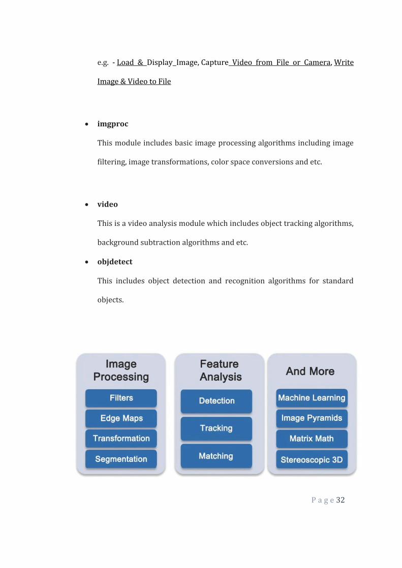
2.2.1 OpenCV Modules
OpenCV has a modular structure. The main modules of OpenCV are listed below.
core
This is the basic module of OpenCV. It includes basic data structures (e.g.-
Mat data structure) and basic image processing functions. This module is
also extensively used by other modules like highgui, etc.
highgui
This module provides simple user interface capabilities, several image
and video codecs, image and video capturing
capabilities, manipulating image windows, handling track bars and mouse
events and etc. If you want more advanced UI capabilities, you have to
use UI frameworks like Qt, WinForms, etc.
P a g e 32
e.g. - Load & Display Image, Capture Video from File or Camera, Write
Image & Video to File
imgproc
This module includes basic image processing algorithms including image
filtering, image transformations, color space conversions and etc.
video
This is a video analysis module which includes object tracking algorithms,
background subtraction algorithms and etc.
objdetect
This includes object detection and recognition algorithms for standard
objects.
P a g e 33
Morphological operations
Morphological image processing is a collection of non-linear operations
related to the shape or morphology of features in an image. According
to Wikipedia, morphological operations rely only on the relative ordering of pixel
values, not on their numerical values, and therefore are especially suited to the
processing of binary images. Morphological operations can also be applied to
grayscale images such that their light transfer functions are unknown and
therefore their absolute pixel values are of no or minor interest.
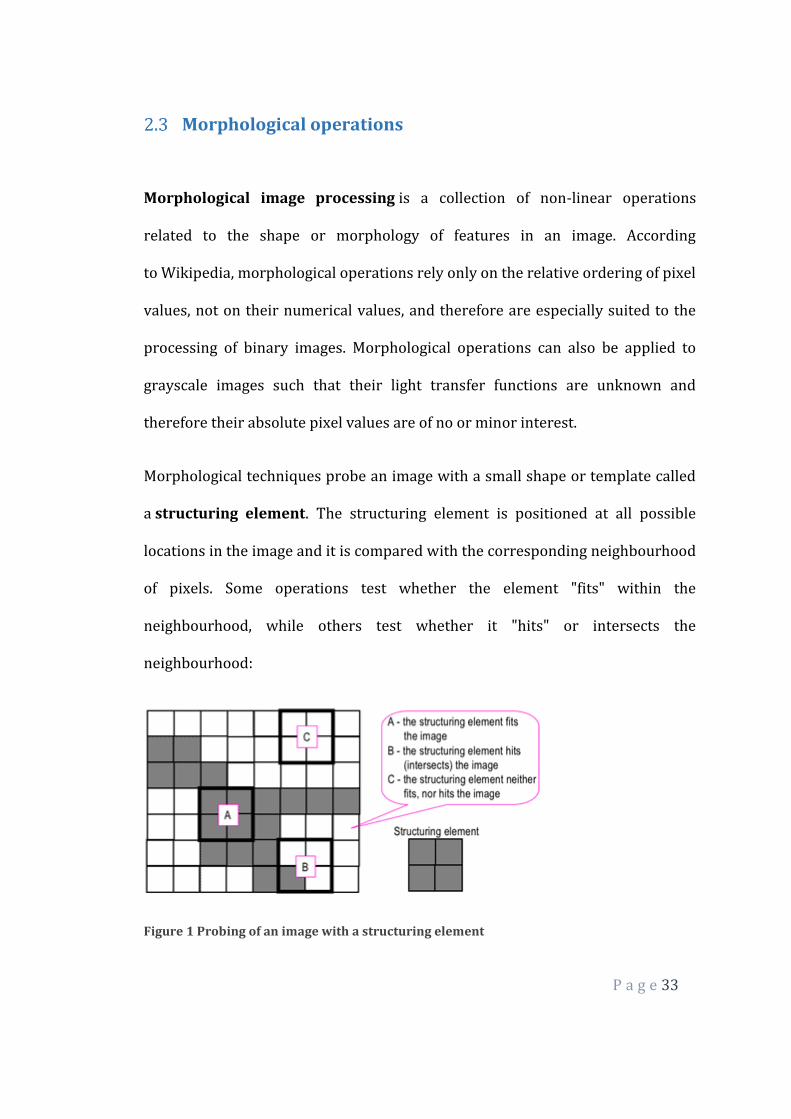
Morphological techniques probe an image with a small shape or template called
a structuring element. The structuring element is positioned at all possible
locations in the image and it is compared with the corresponding neighbourhood
of pixels. Some operations test whether the element "fits" within the
neighbourhood, while others test whether it "hits" or intersects the
neighbourhood:
Figure 1 Probing of an image with a structuring element
P a g e 34
(white and grey pixels have zero and non-zero values, respectively).
A morphological operation on a binary image creates a new binary image in
which the pixel has a non-zero value only if the test is successful at that location
in the input image.
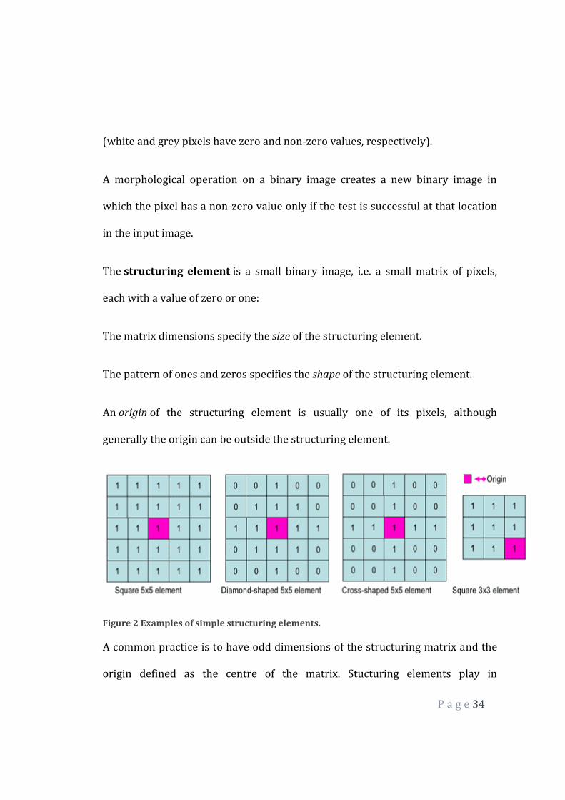
The structuring element is a small binary image, i.e. a small matrix of pixels,
each with a value of zero or one:
The matrix dimensions specify the size of the structuring element.
The pattern of ones and zeros specifies the shape of the structuring element.
An origin of the structuring element is usually one of its pixels, although
generally the origin can be outside the structuring element.
Figure 2 Examples of simple structuring elements.
A common practice is to have odd dimensions of the structuring matrix and the
origin defined as the centre of the matrix. Stucturing elements play in

P a g e 35
moprphological image processing the same role as convolution kernels in linear
image filtering.
When a structuring element is placed in a binary image, each of its pixels is
associated with the corresponding pixel of the neighbourhood under the
structuring element. The structuring element is said to fit the image if, for each of
its pixels set to 1, the corresponding image pixel is also 1. Similarly, a structuring
element is said to hit, or intersect, an image if, at least for one of its pixels set to 1
the corresponding image pixel is also 1.
Figure 3 Fitting and hitting of a binary image with structuring elements s1 and s2.
Zero-valued pixels of the structuring element are ignored, i.e. indicate points
where the corresponding image value is irrelevant.
Fundamental operations
More formal descriptions and examples of how basic morphological operations
work are given in the Hypermedia Image Processing.

P a g e 36
2.3.1 Erosion and dilation
The erosion of a binary image f by a structuring element s (denoted f s)
produces a new binary image g = f s with ones in all locations (x,y) of a
structuring element's origin at which that structuring element s fits the input
image f, i.e. g(x,y) = 1 is s fits f and 0 otherwise, repeating for all pixel coordinates
(x,y).
Figure 4 Grayscale image
Figure 5 Binary image by thresholding
Figure 6 Erosion: a 2×2 square structuring element
Erosion with small (e.g. 2×2 - 5×5) square structuring elements shrinks an image
by stripping away a layer of pixels from both the inner and outer boundaries of
regions. The holes and gaps between different regions become larger, and small

P a g e 37
details are eliminated:
Figure 7 Erosion: a 3×3 square structuring element
Larger structuring elements have a more pronounced effect, the result of erosion
with a large structuring element being similar to the result obtained by iterated
erosion using a smaller structuring element of the same shape. If s1 and s2 are a
pair of structuring elements identical in shape, with s2 twice the size of s1, then
f s2 ≈ (f s1) s1.
Erosion removes small-scale details from a binary image but simultaneously
reduces the size of regions of interest, too. By subtracting the eroded image from
the original image, boundaries of each region can be found: b = f − (f s
) where f is an image of the regions, s is a 3×3 structuring element, and b is an
image of the region boundaries.
P a g e 38
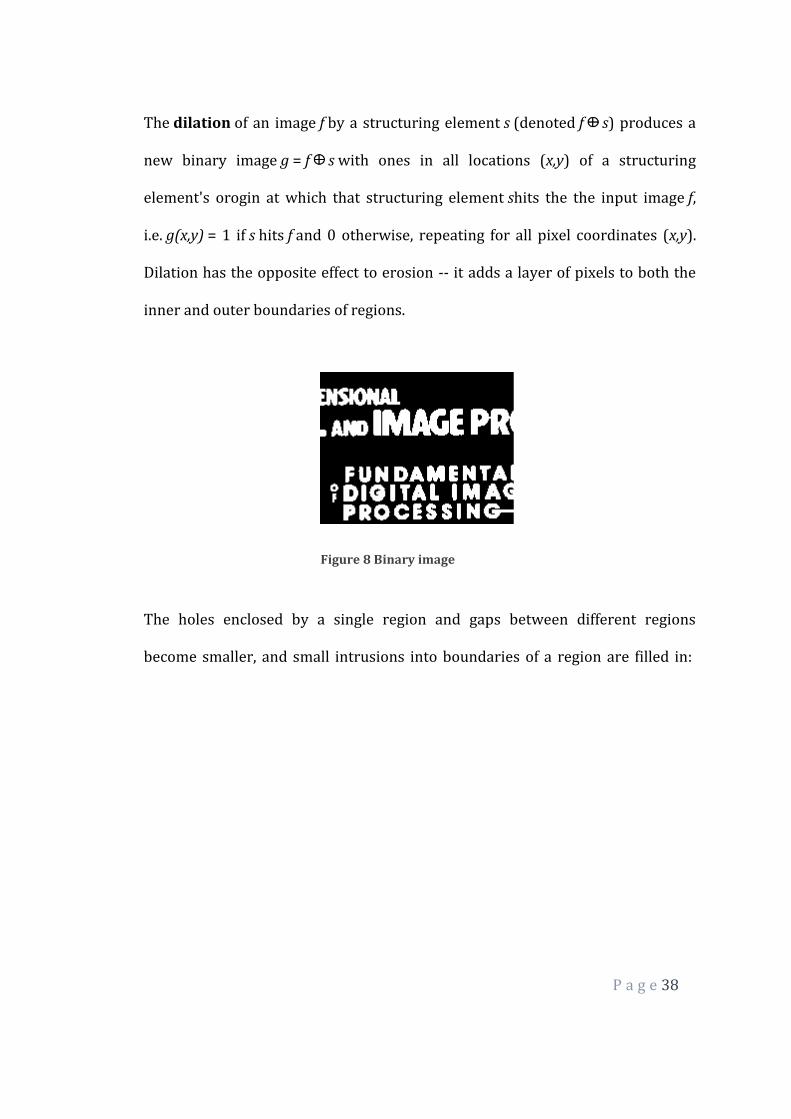
The dilation of an image f by a structuring element s (denoted f s) produces a
new binary image g = f s with ones in all locations (x,y) of a structuring
element's orogin at which that structuring element shits the the input image f,
i.e. g(x,y) = 1 if s hits f and 0 otherwise, repeating for all pixel coordinates (x,y).
Dilation has the opposite effect to erosion -- it adds a layer of pixels to both the
inner and outer boundaries of regions.
Figure 8 Binary image
The holes enclosed by a single region and gaps between different regions
become smaller, and small intrusions into boundaries of a region are filled in:

P a g e 39
Figure 9 Dilation: a 3×3 square structuring element
Results of dilation or erosion are influenced both by the size and shape of a
structuring element. Dilation and erosion are dual operations in that they have
opposite effects. Let f c denote the complement of an image f, i.e., the image
produced by replacing 1 with 0 and vice versa. Formally, the duality is written as:
f s = f c srot
where srot is the structuring element s rotated by 180 . If a structuring element is
symmetrical with respect to rotation, then srot does not differ from s. If a binary
image is considered to be a collection of connected regions of pixels set to 1 on a
background of pixels set to 0, then erosion is the fitting of a structuring element
to these regions and dilation is the fitting of a structuring element (rotated if
necessary) into the background, followed by inversion of the result.
Compound operations

P a g e 40
Many morphological operations are represented as combinations of erosion,
dilation, and simple set-theoretic operations such as the complement of a binary
image:
f c(x,y) = 1 if f(x,y) = 0, and f c(x,y) = 0 if f(x,y) = 1,
the intersection h = f ∩ g of two binary images f and g:
h(x,y) = 1 if f(x,y) = 1 and g(x,y) = 1, and h(x,y) = 0 otherwise,
and the union h = f ∪ g of two binary images f and g:
h(x,y) = 1 if f(x,y) = 1 or g(x,y) = 1, and h(x,y) = 0 otherwise:
Figure 10 Set operations on binary images
The opening of an image f by a structuring element s (denoted by f s) is an
erosion followed by a dilation:
f s = ( f s) s
P a g e 41
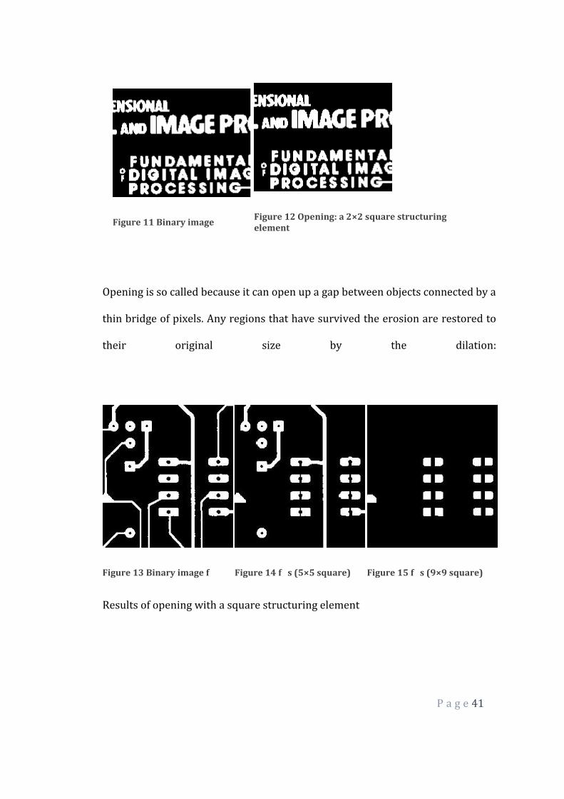
Figure 11 Binary image
Figure 12 Opening: a 2×2 square structuring element
Opening is so called because it can open up a gap between objects connected by a
thin bridge of pixels. Any regions that have survived the erosion are restored to
their original size by the dilation:
Figure 13 Binary image f
Figure 14 f s (5×5 square)
Figure 15 f s (9×9 square)
Results of opening with a square structuring element

P a g e 42
Opening is an idempotent operation: once an image has been opened,
subsequent openings with the same structuring element have no further effect
on that image:
(f s) s) = f s.
The closing of an image f by a structuring element s (denoted by f • s) is a
dilation followed by an erosion:
f • s = ( f srot) srot
Figure 16 Binary image
Figure 17 Closing: a 2×2 square structuring element
In this case, the dilation and erosion should be performed with a rotated by 180
structuring element. Typically, the latter is symmetrical, so that the rotated and
initial versions of it do not differ.

P a g e 43
Figure 18 Closing with a 3×3 square structuring element
Closing is so called because it can fill holes in the regions while keeping the initial
region sizes. Like opening, closing is idempotent: (f • s) • s = f • s, and it is dual
operation of opening (just as opening is the dual operation of closing):
f • s = (f c s)c; f s = (f c • s)c.
In other words, closing (opening) of a binary image can be performed by taking
the complement of that image, opening (closing) with the structuring element,
and taking the complement of the result.
Morphological filtering of a binary image is conducted by considering
compound operations like opening and closing as filters. They may act as filters
of shape. For example, opening with a disc structuring element smooths corners
from the inside, and closing with a disc smooths corners from the outside. But
also these operations can filter out from an image any details that are smaller in
size than the structuring element, e.g. opening is filtering the binary image at a
P a g e 44
scale defined by the size of the structuring element. Only those portions of the
image that fit the structuring element are passed by the filter; smaller structures
are blocked and excluded from the output image. The size of the structuring
element is most important to eliminate noisy details but not to damage objects of
interest.
RASPBERRY PI
Raspberry Pi is a credit card size mini computer used as the micro controller.
Why are we using Raspberry Pi:
Comparison between Arduino Uno, Raspberry Pi and Beaglebone Black[10]:
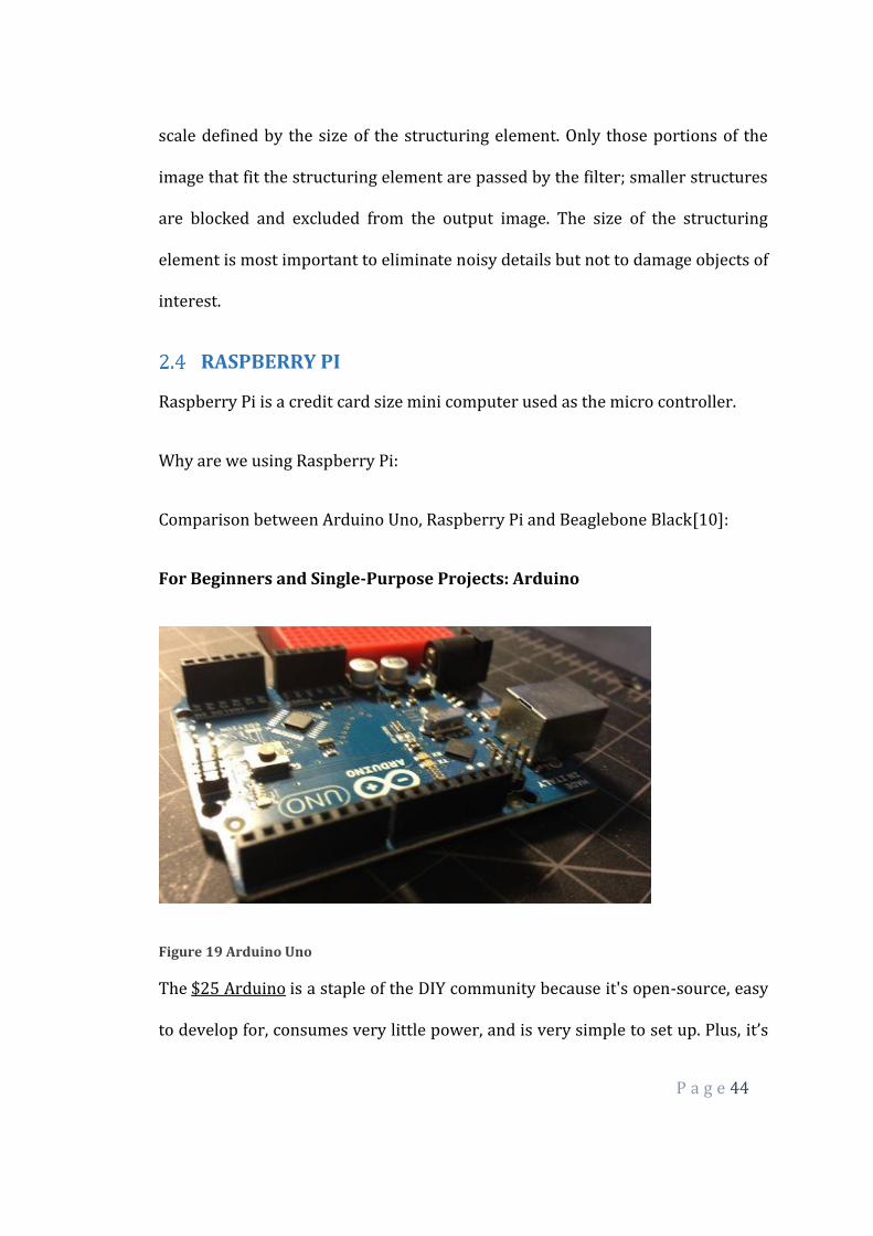
For Beginners and Single-Purpose Projects: Arduino
Figure 19 Arduino Uno
The $25 Arduino is a staple of the DIY community because it's open-source, easy
to develop for, consumes very little power, and is very simple to set up. Plus, it’s

P a g e 45
designed specifically for beginners, so pretty much anyone can play with it and
connect it to external components. Essentially, the Arduino is a small,
programmable board that accepts and stores code from your computer. It's
capable of simple, but cool things like controlling lights or programming
gardening systems. The board, the programming language, and most projects
you find are open-source so you can use them to suit your own needs.
If nothing else, the Arduino is a perfect starting point for anyone looking to get
into DIY electronics because it's very easy to use and hard to mess up.
Advantages: At $30, the Arduino is cheap enough that you can buy a few to mess
around with. Alongside the flagship Arduino Uno, you have a ton of other
variations of the Arduino to choose from. The Arduino also consumes very little
power, so it's perfect for projects that run all day long, or need to be powered
with batteries. Most importantly, the Arduino is insanely popular, so it's easy to
find support, tutorials, and projects. Finally, the Arduino is flexible and can
interface with just about anything.
Disadvantages: The Arduino is a beginner board, but it still takes a little while to
get used to using something without a graphic interface. Because it's cheap and
small, the Arduino can't usually handle a lot of different processes at once, so it's
not good for projects that are incredibly complicated or require a lot of
computing power.

P a g e 46
What the Arduino is best for: The Arduino is best suited for single-purpose
projects. Say, a system where your dryer sends you a text message when your
clothes are done or a video doorbell system. The Arduino is also really well
suited for interacting with objects in the real world, so if you need to interface
with something like window blinds or a door lock the Arduino is a good place to
start. So, if you're designing something simple like a control panel for a garden,
an Arduino is perfect. If you need that control panel to connect to the internet,
have a multi-touch display, and feature full automation, the Arduino probably
won't work.
For Complex, Multimedia, or Linux-Based Projects: Raspberry Pi
Figure 20 Raspberry Pi
The $35 Raspberry Pi has been a DIY-darling since it was first announced. It's
essentially a tiny computer that runs Linux from an SD card, and from there you
can run all sorts of DIY projects. It's essentially a low-powered Linux computer,

P a g e 47
and subsequently can do anything a Linux machine can for only $35. With the
two USB ports and the HDMI out, you can use the Raspberry Pi just like you
would any computer, and that means it's perfect for all sorts of projects that
require a Linux system.
Subsequently, the Raspberry Pi is good for anything you're making that requires
a display, and especially any projects you want to connect to the internet.
Remember, it's basically a tiny computer, so provided you're not looking to do
anything super complicated with it, the Raspberry Pi can handle a ton of
different things.
Advantages: Being a tiny computer comes with all kinds of advantages. For one,
the Raspberry Pi's HDMI port means it's easy to plug into a TV, and the two USB
ports make it so you can operate it like a computer with a mouse and keyboard
easily. It also has an ethernet port built in, so you can easily connect to the
internet with little hassle. Since the operating system runs off a SD card, you can
also change operating systems easily by simply swapping out the card. This is
pretty handy considering you have a few options for the operating system. For
the price, the Raspberry Pi is powerful but still easy enough for beginners to use.
Disadvantages: The Raspberry Pi is awesome for just about any project you'd
use a computer for, but unlike the Arduino and BeagleBone, it doesn't have as
many options to interface with external sensors or buttons. So if you want to do a
P a g e 48
project that's interfacing with other electronics in your home, or lights around
the house, the Raspberry Pi isn't quite as solid of an option.
What the Raspberry Pi is best for: The Raspberry Pi is best suited for projects
that requires a graphic interface or the internet. Since its origins lie in education,
it's also best suited for beginners looking for a low-cost educational computing
project. Because of its various inputs and outputs, it also tends to be the prefered
board for multimedia projects like an XBMC Media Center or an all-in-one retro
game center.
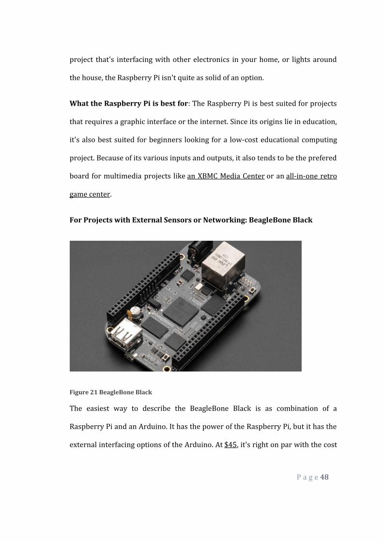
For Projects with External Sensors or Networking: BeagleBone Black
Figure 21 BeagleBone Black
The easiest way to describe the BeagleBone Black is as combination of a
Raspberry Pi and an Arduino. It has the power of the Raspberry Pi, but it has the
external interfacing options of the Arduino. At $45, it's right on par with the cost
P a g e 49
of either, but it manages to do enough things differently that it's in a world of its
own.
Since it doesn't actually require a display like the Pi to setup, the BeagleBone
Black is targeted more at advanced users and serious developers. Still, it has
the Angstrom Linux distro installed from the start, so like the Pi, you can use it as
standalone computer if you like. You can also install a wide variety of other
operating systems, including Android. The BeagleBone Black is a tougher system
to get used to than the Raspberry Pi because it wasn't initially targeted as an
education system, but you can do a lot with it.
Advantages: The BeagleBone comes packed with flash memory and an operating
system already installed, which means that out of the box it's already fully
operational. If you want to run in headless mode (without a monitor), it's easy to
do, and you don't need extra hardware to set it up like you would with the
Raspberry Pi. The big advantage for the BeagleBone is that it has a really good
set of input/output features (69 GPIO pins compared to the Raspberry Pi's eight)
so it can interface with exterior electronics easily.
Disadvantages: The BeagleBone doesn't have as many USB ports as the
Raspberry Pi, nor does it have video encoding built in, so it's not really that great
as a standalone computer or entertainment system. It also doesn't have quite the
same amount of fervor around it as the Raspberry Pi, so while the community
around the BeagleBone is strong, it's not nearly as loud as the Raspberry Pi. That
means tutorials and project ideas are a little harder to come by.
P a g e 50
What the BeagleBone is best for: The BeagleBone is best suited for projects
that might be a little too complicated for the Arduino, but don't need any
complex graphics like the Raspberry Pi. Since it connects to the internet out of
the box, it's a lot cheaper to use than an Arduino, and since it has a ton of ways to
connect external sensors it's perfect for advanced projects that interface with the
real world.

P a g e 51
3 METHODOLOGY
Irrespective of the process model employed, software development comprises
several tasks. Requirements acquisition, conceptual modeling, risk-analysis,
database design, coding, testing and software maintenance are some of the tasks
involved. Further, each task entails a specific set of skills for its accomplishment.
For example, the ability to prepare test suites is important for testing while
coding requires a good practice of programming skills.
The strength of a team is derived from the skills its members possess. According
to the members’ skills, each team can accomplish different software
development tasks with varying levels of expertise. We have discussed in detail
about the objectives and motivations behind the conceptualization in the
previous sections.
In this section, we are going to discuss about the modular high level architecture
describing various modules and interaction among these modules.
Architecture of our development cycle can be mainly divided into three stages
namely:-
Robotics is a branch of research that is becoming crucial to support human
activities, with the development of robots that guarantee reliability, range, speed
and security which they are applied. In most of these applications the robot
interprets the outside environment through the perception, that is, by
recognizing information using artificial receptors, this enables the system to
P a g e 52
have a sense element which can recognize a characteristic such as color, shape or
texture through a system of Computer Vision.
We thought of creating an interface and remotely access the Raspberry Pi and
view everything that is happening quickly and we do not have much
computational cost.
We learned that in computer vision, the task of segmentation of color has a very
low computational cost, and so we chose this task and this kind of feature can be
implemented in many programming languages and these languages depending
on the platform by the way accept robotic resources.
Main Technologies of the Project
Figure 22 Main Technologies in this project
The major technologies in this project are OpenCV, Raspberry Pi and Python
which are majorly introduced in the Literature Survey of this thesis.
P a g e 53
The goal of computer vision is to enable the artificial means, such as computers,
having the ability to sense the external environment, can understand it, take
appropriate measures or decisions, learn from this experience so they can
improve their future performance.
An artificial vision system is a reflection of the natural vision system, it is
possible to achieve, for example, in nature, tracing certain targets such as
predators, food and even objects that may be in the path of an individual through
the vision and learning. Thus, a major goal of an image is to inform the viewer of
your content, allowing it to make decisions. An important subtask in this
computer vision system is image segmentation, which is the process of dividing
the image into a set of individual regions, segments or number. Which consists of
partitioning an image into meaningful regions, grouping them before seeking a
common characteristic, such as color, edge and shape.
Color segmentation uses color to classify areas in the image separating objects
that do not have the same characteristic color. It is common for a computer
vision system aims to make the reconstruction of the external environment,
specifically, the objects in which the first goal is to achieve the object location
with certainty and reliability. The color of the object is a feature used to separate
different areas and subsequently enable the use of a tracking module. So this
feature was chosen to be studied and implemented.
P a g e 54
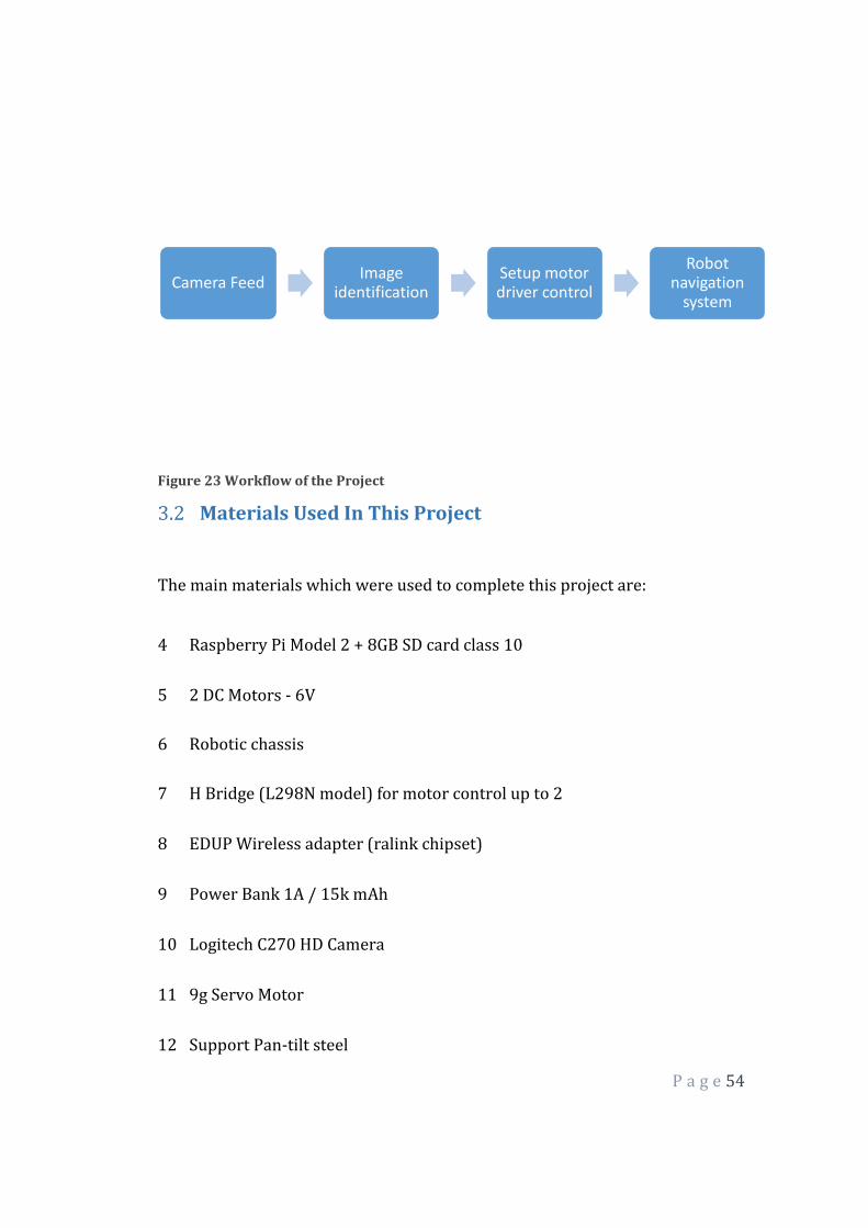
Figure 23 Workflow of the Project
Materials Used In This Project
The main materials which were used to complete this project are:
4 Raspberry Pi Model 2 + 8GB SD card class 10
5 2 DC Motors - 6V
6 Robotic chassis
7 H Bridge (L298N model) for motor control up to 2
8 EDUP Wireless adapter (ralink chipset)
9 Power Bank 1A / 15k mAh
10 Logitech C270 HD Camera
11 9g Servo Motor
12 Support Pan-tilt steel
Camera FeedImage
identificationSetup motor driver control
Robot navigation
system

P a g e 55
13 Jumpers (M-M, M-F and F-F)
14 4 AA 1.5V batteries mAh 6k
15 Cables plastic
16 Sinks and thermal paste
Figure 24 Raspberry Pi 2

P a g e 56
Figure 25 Wireless adapter
Figure 26 Logitech C270 HD Webcam
Figure 27 Castor Wheel
Figure 28 6V DC Motors
P a g e 57
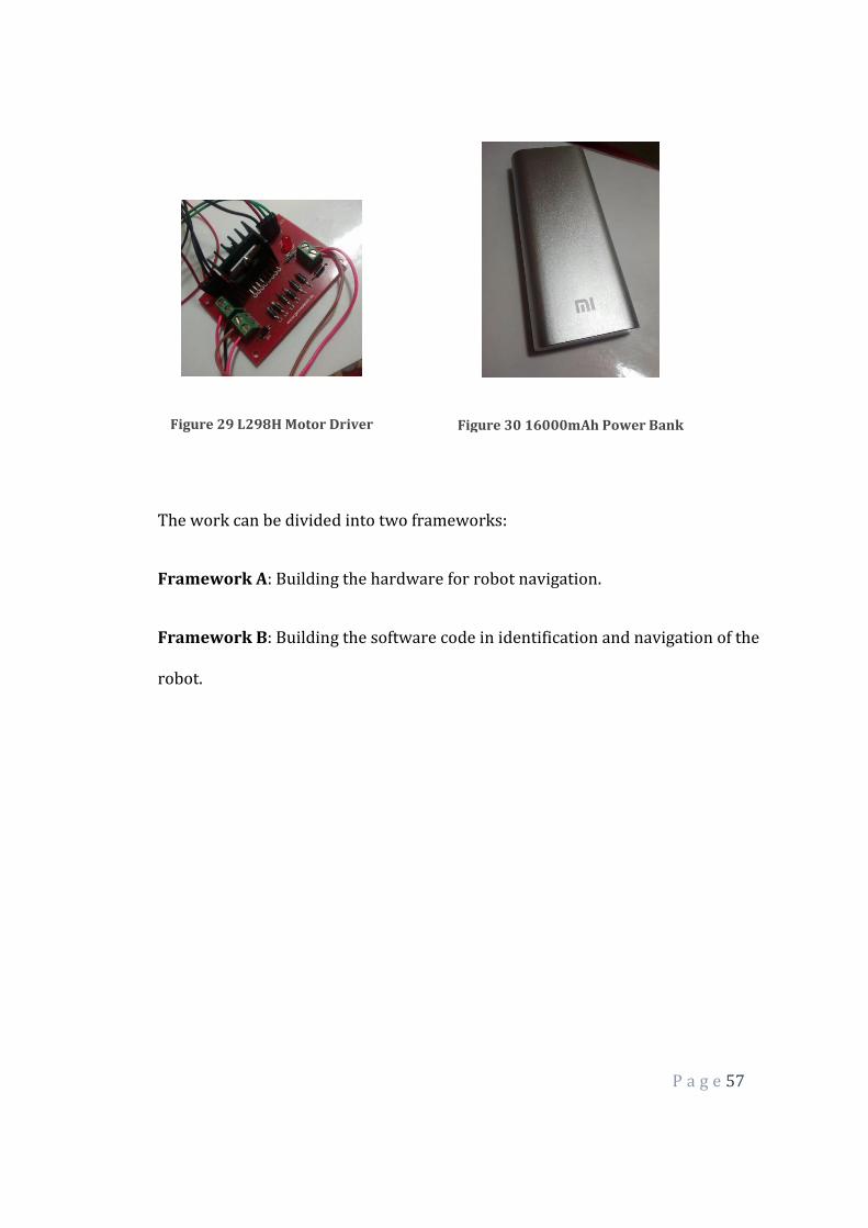
Figure 29 L298H Motor Driver
Figure 30 16000mAh Power Bank
The work can be divided into two frameworks:
Framework A: Building the hardware for robot navigation.
Framework B: Building the software code in identification and navigation of the
robot.
P a g e 58
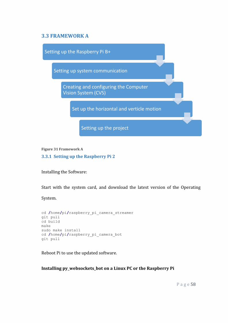
3.3 FRAMEWORK A
Figure 31 Framework A
3.3.1 Setting up the Raspberry Pi 2
Installing the Software:
Start with the system card, and download the latest version of the Operating
System.
cd /home/pi/raspberry_pi_camera_streamer
git pull
cd build
make
sudo make install
cd /home/pi/raspberry_pi_camera_bot
git pull
Reboot Pi to use the updated software.
Installing py_websockets_bot on a Linux PC or the Raspberry Pi
Setting up the Raspberry Pi B+
Setting up system communication
Creating and configuring the Computer Vision System (CVS)
Set up the horizontal and verticle motion
Setting up the project
P a g e 59
Run the following commands to install the libraries dependencies:
sudo apt-get update
sudo apt-get install python-opencv
git clone https://bitbucket.org/DawnRobotics/py_websockets_bot.git
cd py_websockets_bot
sudo python setup.py install
Making the Robot Move
Making the robot move is very straightforward, as shown in the code snippet
below:
import py_websockets_bot
bot = py_websockets_bot.WebsocketsBot( "ROBOT_IP_ADDRESS" )
bot.set_motor_speeds( -80.0, 80.0 ) # Spin left
For ROBOT_IP_ADDRESS we put “192.168.42.1″ or “localhost” if the script was
running on the robot. The code snippet connects to the robot, and then starts it
turning left by setting the left motor to -80% speed and the right motor to +80%
speed.
3.3.2 THE CAMERA
The system chosen for the webcam is auto detected after plugging in the USB
port on the Raspberry Pi. We use the lsusb command which was seen in the
detection of peripheral. For viewing webcam streaming software, which is a way
to transmit multimedia data via packets temporarily stored in the cache
Raspberry Pi is required.

P a g e 60
3.3.3 System Communication
Figure 32 System Communication
The connectivity of the system can be done in two ways: wired (Ethernet LAN
connection 10 / 1mg) and wireless (connection by a USB wireless adapter). The
choice was the wireless communication in order to allow mobility to the system.
Before installing the wireless adapter is necessary to know some of your
information such as your Service Set Identifier (SSID), which is the set of
characters that identifies a wireless network, also know the type of encryption
used on the network, the network type wireless connection and the adapter to be
addressed by the system and functioning properly, we must install your
firmware, a package of software available as model the internal chip adapter.
For choosing a study based on wireless adapters compatible with the Raspberry
Pi was done through the official website. The adapter was chosen to model the
EDUP N8531 USB LAN ADAPTER with a frequency of 2 dBi antenna, it was
P a g e 61
chosen to have a reasonable range of the access point and provide easy
installation.
To make remote communication in order to access information, upload /
download files and perform necessary testing was all computers belong to the
same network, that is, both computers to be connected to an access point. And to
accomplish these tasks some communication protocols were used:
GUI - GRAPHIC USER INTERFACE
To remotely access a GUI on Raspberry PI was required an RDP or VNC protocol
and a connection encrypts good quality.
Access via VNC protocol: it is necessary to install the software on your computer
and UVCViewer the Raspberry Pi[9] that TightVNC is a free suite of remote
control software has been installed.
Server installation: sudo apt-get install tightvncserver
Startup: tightvncserver
It creates a default session: vncserver :1 -geometry 1024×728 -depth 24
Access via RDP protocol: it is necessary to install the software
andRDPDesk Raspberry Pi[9] XRDP server that automatically starts the boot was
installed.
Server installation: sudo apt-get install xrdp
COMMAND LINE

P a g e 62
Access via the command line was necessary to perform maintenance, upgrades
and scripts for command lines which is quite practical. In the remote access
machine Putty software that creates an SSH access protocol using IP access to the
Raspberry Pi[9] was installed and it performs the installation of the service only
once.
Server installation: sudo apt-get install ssh
FILE TRANSFER
All previous communication protocols are limited in the direct transfer of files,
so an option is found via FTP protocol, is the standard of the existing TCP / IP
oriented to transfer files, it is independent of operating system or hardware. Is
all important for performing analysis of scripts and data exchange with the
Raspberry Pi[9], for it was used in WinSCP access computer software along with
IP destination to exchange files.
After configuring the media, the process of creating scripts for computer vision
and robotic integration of the resources was initiated.
3.3.4 Horizontal and Vertical motion control of the system
Having made the segmentation and extraction of information from the object in
the image, some techniques in order to ensure the execution of functions that
enable the dynamic chassis in front of the segmented object were used. There are
three kinds of movements, in order to interact with the external environment,

P a g e 63
using the software and the hardware in a more complete manner. The changes
refer to the location of the object and refer to the use of their depth and / or
location:
Forward
Brings
Right
Left
Upward movement of the camera
Lower camera movement
But with DC motors and the chassis robotic is made movement forward,
backward, left and right. The horizontal & depth adjustment movement of the
coordinate system is done by assuming binary-encoded digital pulses per pin
only two values (0 and 1) performed by the control module, the H-bridge
through the input pin (input). These pins are connected by jumpers and
connected via GPIO on RPI, the script is necessary to import the GPIO library and
declare the use of GPIO mode:
sudo apt-get install python-rpi.gpio
The images of this step describes all the connections for the total operation of
robotic chassis near the H-bridge and motor and feeding was made using 4 AA
P a g e 64
batteries 1.5V each resulting in 6 V and 6000mAh. The source code was
necessary to import this library and also choose the mode of GPIO.
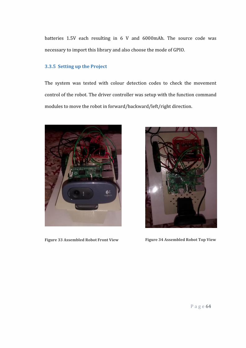
3.3.5 Setting up the Project
The system was tested with colour detection codes to check the movement
control of the robot. The driver controller was setup with the function command
modules to move the robot in forward/backward/left/right direction.
Figure 33 Assembled Robot Front View
Figure 34 Assembled Robot Top View
P a g e 65
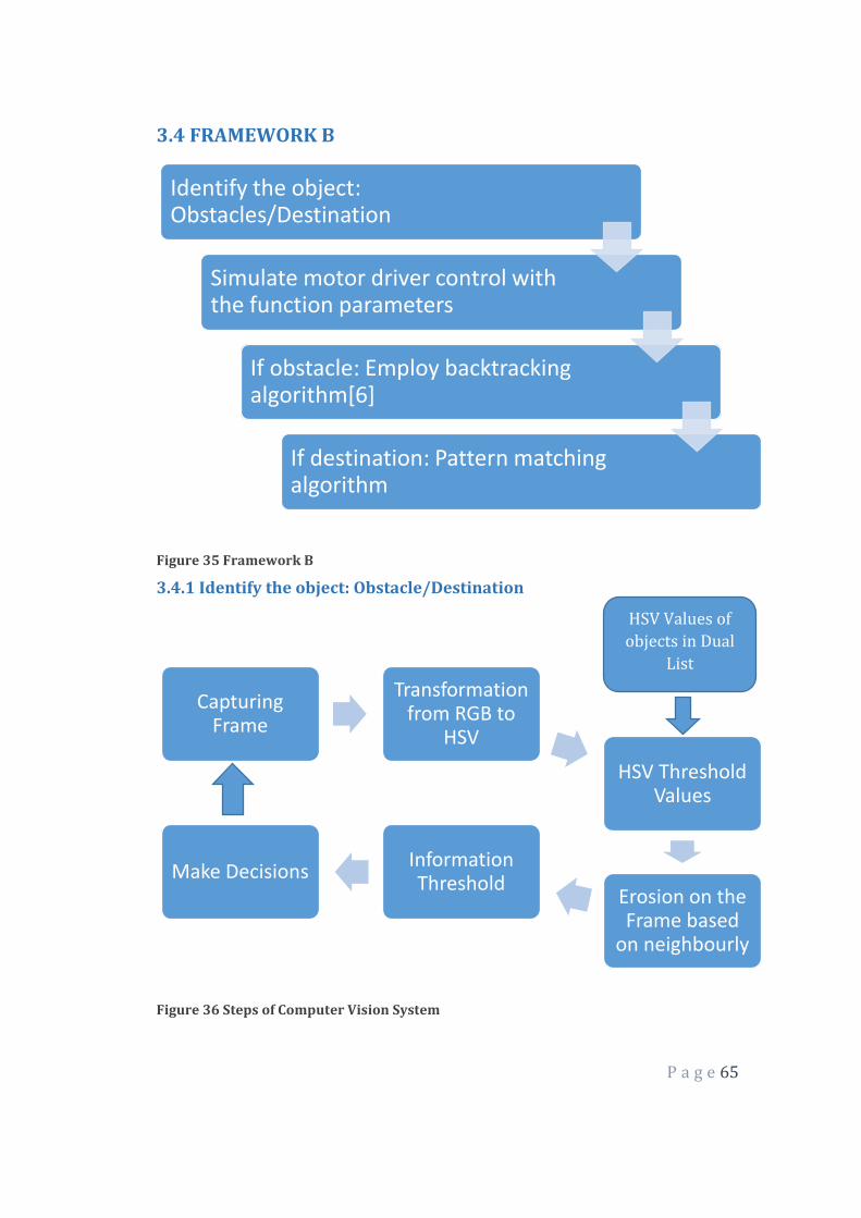
3.4 FRAMEWORK B
Figure 35 Framework B
3.4.1 Identify the object: Obstacle/Destination
Figure 36 Steps of Computer Vision System
Identify the object: Obstacles/Destination
Simulate motor driver control with the function parameters
If obstacle: Employ backtracking algorithm[6]
If destination: Pattern matching algorithm
Capturing Frame
Transformation from RGB to
HSV
HSV Threshold Values
Erosion on the Frame based
on neighbourly
Information Threshold
Make Decisions
HSV Values of
objects in Dual
List
P a g e 66
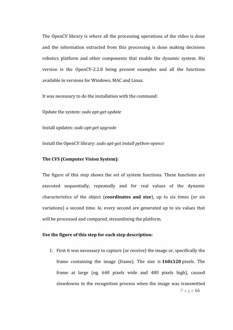
The OpenCV library is where all the processing operations of the video is done
and the information extracted from this processing is done making decisions
robotics platform and other components that enable the dynamic system. His
version is the OpenCV-2.2.8 being present examples and all the functions
available in versions for Windows, MAC and Linux.
It was necessary to do the installation with the command:
Update the system: sudo apt-get update
Install updates: sudo apt-get upgrade
Install the OpenCV library: sudo apt-get install python-opencv
The CVS (Computer Vision System):
The figure of this step shows the set of system functions. These functions are
executed sequentially, repeatedly and for real values of the dynamic
characteristics of the object (coordinates and size), up to six times (or six
variations) a second time. Ie, every second are generated up to six values that
will be processed and compared, streamlining the platform.
Use the figure of this step for each step description:
1. First it was necessary to capture (or receive) the image or, specifically the
frame containing the image (frame). The size is 160x120 pixels. The
frame at large (eg, 640 pixels wide and 480 pixels high), caused
slowdowns in the recognition process when the image was transmitted
P a g e 67
remotely. The system default is RGB colour, this colour system is
represented in the webcam frame obtained through the basic colours: red
(Red), Green (Green) and blue (Blue). These colours are represented on a
pixel by pixel dimensional vector, for example, the colour red is
represented 0com values (0, 255, 0), respectively represented for each
channel. That is, each pixel has its RGB value represented by three bytes
(red green and blue).
2. After the captured image, the conversion from RGB colour system to the
colour HSV (hue, saturation, and value) was undertaken, since this
model describes similar to the recognition by the human eye colours.
Since the RGB (red, green and blue) system has the colours based on
combinations of the primary colours (red, green and blue) and the HSV
system defines colours as their colour, sparkle and shine (hue, saturation,
and value), facilitating the extraction of information. In diagram the step 2
shows the conversion from RGB to HSV, using the "cvtColor" native
OpenCV[2], which converts the input image from an input colour system
to another function.
3. With the image in HSV model, it was necessary to find the correct values
of HSV minimum and maximum color of the object that will be followed.
To save these values, were made two vectors with minimal HSV and HSV
maximum color object as values: minimum Hue (42) Minimum
saturation (62) Minimum brightness (63) Maximum Hue (92)
P a g e 68
Maximum Saturation (255) Maximum Brightness (235). So the next
step to generate a binary image, the relevant information may be limited
only in the context of these values. These values are needed to limit the
color pattern of the object. A function of comparing the pixel values with
the standard values of the inserted vector was used. The result was a
binary image providing only one value for each pixel.
4. Having made the segmentation, resulting in the binary image, it is noted
that noise are still present in the frame. These noises are elements that
hinder the segmentation (including obtaining the actual size) of the
object. To fix (or attempt to fix) this problem, it was necessary to apply a
morphological transformation through operators in the frame, so that the
pixels were removed that did not meet the desired standard. For this, the
morphological operator EROSION, who performed a "clean" in the frame,
reducing noise contained in it was used.
5. Then it was used to "Moments" function, which calculates the moments
of positive contour (white) using an integration of all pixels present in the
contour. This feature is only possible in a frame already binarizado and
without noise, so that the size of the contour of the object is not changed
by stray pixels in the frame, which hinder and cause redundancy in
information.
moments = cv2.moments (imgErode, True)
P a g e 69
6. In the proposed example, it was necessary to find the area of the contour
and its location coordinates in the frame to be made the calculations of
repositioning the chassis. The calculation of the area of the object
performs the binary sum of positive, generating the variable M00 and
recorded in the variable "area":
area = moments ['m00']
The specificity of the contour refers to an object, not a polygon. This value
is found an approximate area of positive pixels (white) that make up the
object. If this value is null area, is disregarded the existence of an object
color treated (if the "green" color) in the frame. Using this feature will
help accomplish the movement of the robot approaching and distancing
of the target object, trying to treat the problem of depth. That is, the fact
that the object is approaching or distancing overly chassis.
And from the targeted area was possible, define the coordinates of the
object in this frame. For the coordinates of the object was used
parameters obtained Moments function that found its coordinated. But
this was coordinated based on centroid of the object, is found only if the
area of the object is greater than zero. Using this feature was important to
make the movement of horizontal and vertical adjustment of the robot in
order to increase the degree of freedom and minimize restriction of
movement of the object to be identified. Using the area of the object
P a g e 70
parameter and combined with M00 x and y parameters Moments of
function, it was possible to find the coordinates (x, y).
Thus the values received in the coordinate (x, y) refers to the placement of the
found segmentation of the object relative to the frame and to facilitate the
interpretation of the information which is being drawn from the coordinate
information, a function that draws a circle at the centroid was applied the
object.
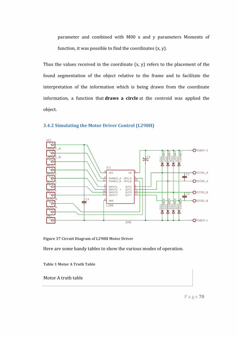
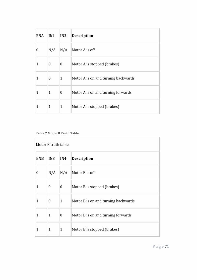
3.4.2 Simulating the Motor Driver Control (L298H)
Figure 37 Circuit Diagram of L298H Motor Driver
Here are some handy tables to show the various modes of operation.
Table 1 Motor A Truth Table
Motor A truth table
P a g e 71
ENA IN1 IN2 Description
0 N/A N/A Motor A is off
1 0 0 Motor A is stopped (brakes)
1 0 1 Motor A is on and turning backwards
1 1 0 Motor A is on and turning forwards
1 1 1 Motor A is stopped (brakes)
Table 2 Motor B Truth Table
Motor B truth table
ENB IN3 IN4 Description
0 N/A N/A Motor B is off
1 0 0 Motor B is stopped (brakes)
1 0 1 Motor B is on and turning backwards
1 1 0 Motor B is on and turning forwards
1 1 1 Motor B is stopped (brakes)
P a g e 72
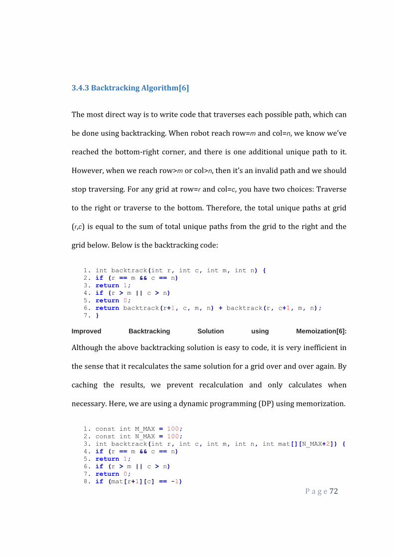
3.4.3 Backtracking Algorithm[6]
The most direct way is to write code that traverses each possible path, which can
be done using backtracking. When robot reach row=m and col=n, we know we’ve
reached the bottom-right corner, and there is one additional unique path to it.
However, when we reach row>m or col>n, then it’s an invalid path and we should
stop traversing. For any grid at row=r and col=c, you have two choices: Traverse
to the right or traverse to the bottom. Therefore, the total unique paths at grid
(r,c) is equal to the sum of total unique paths from the grid to the right and the
grid below. Below is the backtracking code:
1. int backtrack(int r, int c, int m, int n) { 2. if (r == m && c == n) 3. return 1; 4. if (r > m || c > n) 5. return 0; 6. return backtrack(r+1, c, m, n) + backtrack(r, c+1, m, n); 7. }
Improved Backtracking Solution using Memoization[6]:
Although the above backtracking solution is easy to code, it is very inefficient in
the sense that it recalculates the same solution for a grid over and over again. By
caching the results, we prevent recalculation and only calculates when
necessary. Here, we are using a dynamic programming (DP) using memorization.
1. const int M_MAX = 100; 2. const int N_MAX = 100; 3. int backtrack(int r, int c, int m, int n, int mat[][N_MAX+2]) { 4. if (r == m && c == n) 5. return 1; 6. if (r > m || c > n) 7. return 0; 8. if (mat[r+1][c] == -1)

P a g e 73
9. mat[r+1][c] = backtrack(r+1, c, m, n, mat); 10. if (mat[r][c+1] == -1)
11. mat[r][c+1] = backtrack(r, c+1, m, n, mat);
12. return mat[r+1][c] + mat[r][c+1];
13. }
14. int bt(int m, int n) {
15. int mat[M_MAX+2][N_MAX+2];
16. for (int i = 0; i < M_MAX+2; i++) {
17. for (int j = 0; j < N_MAX+2; j++) {
18. mat[i][j] = -1;
19. }
20. }
21. return backtrack(1, 1, m, n, mat);
22. }

P a g e 74
4 Experiments and Results
The main objective of our project was to demonstrate that it is possible to use
the artificial vision for a robot to interact with the external environment, using a
feature such as shape, colour or texture. This characteristic is used as a metric
to determine the movement of the entire robot. The experimental results show
an approval of the algorithm used.
Setting up of the Raspberry Pi[9]: The Raspberry operating system, Raspbian
was successfully set up and configured using the system interface. The following
are some screenshots of the interface. The x-link module was used to configure
the system connection.
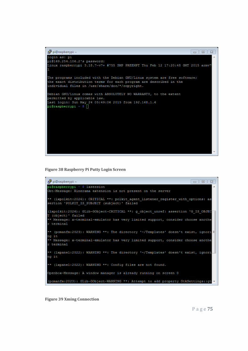
P a g e 75
Figure 38 Raspberry Pi Putty Login Screen
Figure 39 Xming Connection
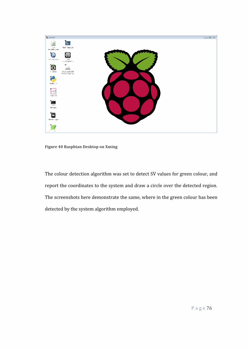
P a g e 76
Figure 40 Raspbian Desktop on Xming
The colour detection algorithm was set to detect SV values for green colour, and
report the coordinates to the system and draw a circle over the detected region.
The screenshots here demonstrate the same, where in the green colour has been
detected by the system algorithm employed.
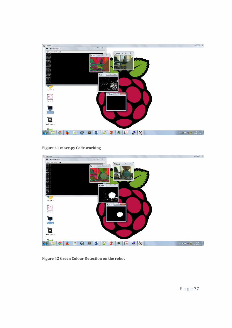
P a g e 77
Figure 41 move.py Code working
Figure 42 Green Colour Detection on the robot
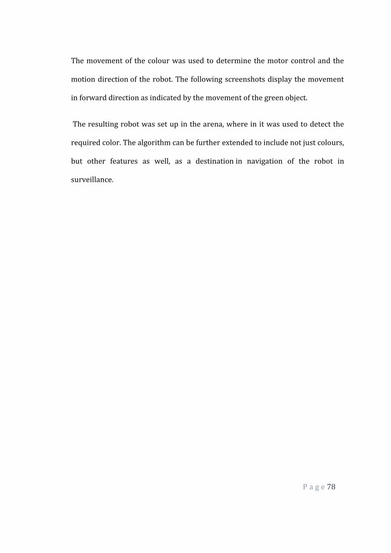
P a g e 78
The movement of the colour was used to determine the motor control and the
motion direction of the robot. The following screenshots display the movement
in forward direction as indicated by the movement of the green object.
The resulting robot was set up in the arena, where in it was used to detect the
required color. The algorithm can be further extended to include not just colours,
but other features as well, as a destination in navigation of the robot in
surveillance.

P a g e 79
5 CONCLUSION
Autonomous obstacle avoidance[12][13] is not an easy task but it is very
important area in developing mobile robots that is need to accomplish
positioning, path planning and navigation. A robot vision system using colour
matching technique to identify the object and traverse the arena using
backtracking algorithm in real time was presented. The system is able to find and
recognize the colour of the obstacle/destination and take action depending on
the path-planning algorithm deployed into it. The technique used is based on
image processing and optimization in real time. Usually a robot backtracking
system is very slow due to computational time used. However, image processing
minimized the time used in detection as compared to active sensors. The system
can perform and satisfactory results are obtained which show that the
proposed vision based system can achieve the desired turn angle thus it can
make the autonomous mobile robot moving to the target.

P a g e 80
6 FUTURE WORKS
As with all such systems dealing with higher-level robotic intelligence, the
performance can never be expected to be completely fool proof. The best that
one can do is to devise appropriate automatic error correction and detection
strategies. To briefly discuss the various failure modes of our system, the vision-
based collision avoidance capability depends obviously on the visual contrast
between the obstacle and the interior of the hallway. The size of the obstacle will
also play an important role in its detectability by vision. It is entirely possible
that superior image processing strategies would enhance the performance of
vision-based collision avoidance.
The robot vision system can be extended to avoid real time moving obstacles,
rather than assuming the obstacles to be only stationary. This kind of a system
can be deployed into an artificially intelligent road crossing system. Moreover,
we can extend the vision processing to identify a particular picture or deploy
machine learning to identify a particular type of object depending on the type of
training data input into it. This kind of a system can have abundant applications,
from an autonomous objet locator t a face follower robot system. Our future
researches seek to address these issue.
P a g e 81
7 REFERENCES
[1] Yasunori ABE Masaru SHIKANO, Toshio FUKUDA, Fumihito ARAI. , Vision
Based Navigation System for Autonomous Mobile Robot with Global
Matching-1999
[2] OpenCV library, www.opencv.org, www.itseez.org
[3] Edward Y.C. Huang. Semi-Autonomous Vision Based navigation System for
a mobile robotic vehicle. Master’s thesis, Massachusetts Institute of
Technology, June 2003.
[4] Jefferson R. Souza, Gustavo Pessin, Fernando S. Osório, Denis F. Wolf.
Vision-Based Autonomous Navigation Using Supervised Learning
Techniques.University of Sao Paulo, 2011.
[5] Chatterjee, Amitava, Rakshit, Anjan, Nirmal Singh, N. Vision Based
Autonomous Robot Navigation. Springer , 2013.
[6] El-Hussieny, H. , Assal, S.F.M. , Abdellatif, M.. Improved Backtracking
Algorithm for Efficient Sensor-Based Random Tree Exploration.
International Conference on Communication Systems and Networks
(CICSyN), June 2013.
[7] Eric T. Baumgartner and Steven B. Skaar. An Autonomous Vision-Based
Mobile Robot. IEEE TRANSACTIONS ON AUTOMATIC CONTROL, VOL. 39,
NO. 3, MARCH 1994
[8] Programming a Raspberry Pi Robot Using Python and OpenCV.
http://blog.dawnrobotics.co.uk/2014/06/programming-raspberry-pi-
robot- using-python-opencv/
[9] Raspberry Pi Model B+ | Raspberry Pi.
http://www.raspberrypi.org/products/model-b-plus
[10] Raspberry Pi, Beaglebone Black, Intel Edison – Benchmarked.
http://www.davidhunt.ie/raspberry-pi-beaglebone-black-intel-edison-
benchmarked/
[11] Mark Nixon. Feature Extraction & Image Processing. Academic
Press, 2008.
[12] Borenstein, J. ; Koren, Y. The vector field histogram-fast obstacle
avoidance for mobile robots. Robotics and Automation, IEEE Transactions
on (Volume:7 , Issue: 3 ), August 2002
P a g e 82
[13] R. Siegwart, I. Nourbakhsh.
http://web.eecs.utk.edu/~leparker/Courses/CS594-fall08/Lectures/Oct-
21-Obstacle-Avoidance-I.pdf
[14] Instructables.com, http://www.instructables.com/id/The-RROP-
RaspRobot-OpenCV-Project/
[15] Giuseppina Gini, Alberto Marchi, Indoor Robot Navigation with
Single Camera Vision
[16] Akihisa Ohya, Akio Kosaka and Avi Kak, Vision-Based Navigation of
Mobile Robot with Obstacle Avoidance by Single Camera Vision and
Ultrasonic Sensing
P a g e 83
APPENDIX A- TOOLS AND PLATFORMS USED
Python
Python is a widely used general-purpose, high-level programming language. Its
design philosophy emphasizes code readability, and its syntax allows
programmers to express concepts in fewer lines of code than would be possible
in languages such as C++ or Java. The language provides constructs intended to
enable clear programs on both a small and large scale.
Python supports multiple programming paradigms, including object-oriented,
imperative and functional programming or procedural styles. It features a
dynamic type system and automatic memory management and has a large and
comprehensive standard library.
Python interpreters are available for installation on many operating systems,
allowing Python code execution on a wide variety of systems. Using third-party
tools, such as Py2exe or Pyinstaller, Python code can be packaged into stand-
alone executable programs for some of the most popular operating systems,
allowing for the distribution of Python-based software for use on those
environments without requiring the installation of a Python interpreter.
CPython, the reference implementation of Python, is free and open-source
software and has a community-based development model, as do nearly all of its
alternative implementations. CPython is managed by the non-profit Python
Software Foundation.
P a g e 84
Ubuntu
Ubuntu (originally /ʊˈbuːntʊ/ uu-boon-tuu, according to the company
website /ʊˈbʊntuː/ uu-buun-too) is a Debian-based Linux operating system,
with Unity as its default desktop environment.
Development of Ubuntu is led by UK-based Canonical Ltd., a company owned by
South African entrepreneur Mark Shuttleworth. Canonical generates revenue
through the sale of technical support and other services related to Ubuntu. The
Ubuntu project is publicly committed to the principles of open-source software
development; people are encouraged to use free software, study how it works,
improve upon it, and distribute it.
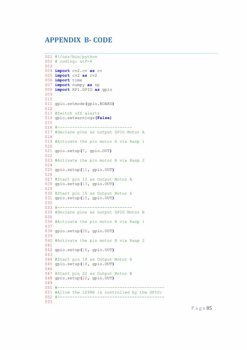
P a g e 85
APPENDIX B- CODE
001 #!/usr/bin/python
002 # coding: utf-8
003
004 import cv2.cv as cv
005 import cv2 as cv2
006 import time
007 import numpy as np
008 import RPi.GPIO as gpio
009
010
011 gpio.setmode(gpio.BOARD)
012
013 #Switch off alerts
014 gpio.setwarnings(False)
015
016 #------------------------------
017 #Declare pins as output GPIO Motor A
018
019 #Activate the pin motor A via Rasp 1
020
021 gpio.setup(7, gpio.OUT)
022
023 #Activate the pin motor A via Rasp 2
024
025 gpio.setup(11, gpio.OUT)
026
027 #Start pin 13 as Output Motor A
028 gpio.setup(13, gpio.OUT)
029
030 #Start pin 15 as Output Motor A
031 gpio.setup(15, gpio.OUT)
032
033 #------------------------------
034 #Declare pins as output GPIO Motor B
035
036 #Activate the pin motor B via Rasp 1
037
038 gpio.setup(26, gpio.OUT)
039
040 #Activate the pin motor B via Rasp 2
041
042 gpio.setup(16, gpio.OUT)
043
044 #Start pin 18 as Output Motor B
045 gpio.setup(18, gpio.OUT)
046
047 #Start pin 22 as Output Motor B
048 gpio.setup(22, gpio.OUT)
049
050 #-------------------------------------------
051 #Allow the L298N is controlled by the GPIO:
052 #-------------------------------------------
053

P a g e 86
054 #Initial values - True - Motor A Activated
055 gpio.output(7, True) #Motor A - Rasp 1
056 gpio.output(11, True) #Motor A - Rasp 2
057
058 #Initial values - True - Motor B Activated
059 gpio.output(26, True) #Motor B - Rasp 1
060 gpio.output(16, True) #Motor B - Rasp 2
061
062 # Motor Left
063
064
065 # Motor Right
066
067 def front():
068 # Motor 1
069 gpio.output(13, True)
070 gpio.output(15, False)
071 # Motor 2
072 gpio.output(18, False)
073 gpio.output(22, True)
074
075 def after():
076 # Motor 1
077 gpio.output(13, False)
078 gpio.output(15, True)
079 # Motor 2
080 gpio.output(18, True)
081 gpio.output(22, False)
082
083 def stop():
084 # Motor 1
085 gpio.output(18, False)
086 gpio.output(22, False)
087 # Motor 2
088 gpio.output(13, False)
089 gpio.output(15, False)
090
091 def right():
092 # Motor 1
093 gpio.output(13, True)
094 gpio.output(15, False)
095 # Motor 2
096 gpio.output(18, True)
097 gpio.output(22, False)
098
099
100 def left():
101 # Motor 1
102 gpio.output(13, False)
103 gpio.output(15, True)
104 # Motor 2
105 gpio.output(18, False)
106 gpio.output(22, True)
107
108 def adjust(area):
109 if(area<=120):
110 front()
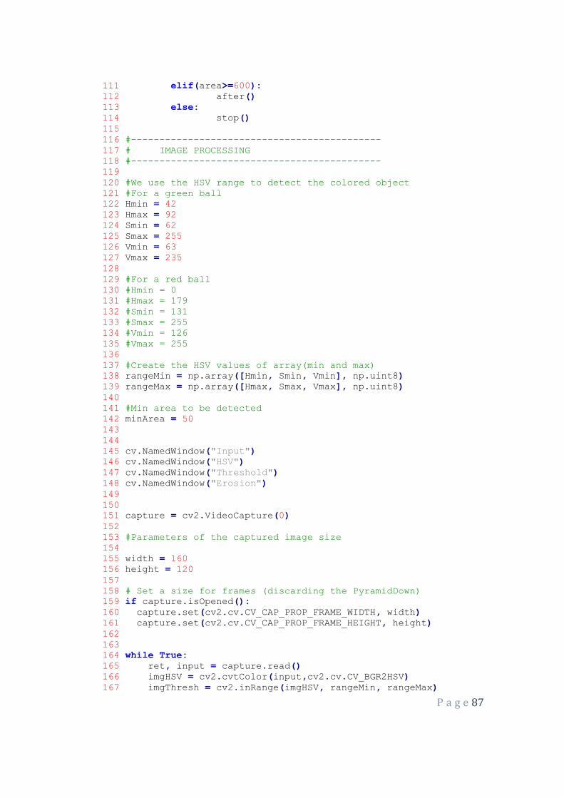
P a g e 87
111 elif(area>=600):
112 after()
113 else:
114 stop()
115
116 #--------------------------------------------
117 # IMAGE PROCESSING
118 #--------------------------------------------
119
120 #We use the HSV range to detect the colored object
121 #For a green ball
122 Hmin = 42
123 Hmax = 92
124 Smin = 62
125 Smax = 255
126 Vmin = 63
127 Vmax = 235
128
129 #For a red ball
130 #Hmin = 0
131 #Hmax = 179
132 #Smin = 131
133 #Smax = 255
134 #Vmin = 126
135 #Vmax = 255
136
137 #Create the HSV values of array(min and max)
138 rangeMin = np.array([Hmin, Smin, Vmin], np.uint8)
139 rangeMax = np.array([Hmax, Smax, Vmax], np.uint8)
140
141 #Min area to be detected
142 minArea = 50
143
144
145 cv.NamedWindow("Input")
146 cv.NamedWindow("HSV")
147 cv.NamedWindow("Threshold")
148 cv.NamedWindow("Erosion")
149
150
151 capture = cv2.VideoCapture(0)
152
153 #Parameters of the captured image size
154
155 width = 160
156 height = 120
157
158 # Set a size for frames (discarding the PyramidDown)
159 if capture.isOpened():
160 capture.set(cv2.cv.CV_CAP_PROP_FRAME_WIDTH, width)
161 capture.set(cv2.cv.CV_CAP_PROP_FRAME_HEIGHT, height)
162
163
164 while True:
165 ret, input = capture.read()
166 imgHSV = cv2.cvtColor(input,cv2.cv.CV_BGR2HSV)
167 imgThresh = cv2.inRange(imgHSV, rangeMin, rangeMax)

P a g e 88
168 imgErode = cv2.erode(imgThresh, None, iterations = 3)
169 moments = cv2.moments(imgErode, True)
170 area = moments['m00']
171 if moments['m00'] >= minArea:
172 print(area)
173 adjust(area)
174 else:
175 stop()
176
177 cv2.imshow("Input",input)
178 cv2.imshow("HSV", imgHSV)
179 cv2.imshow("Threshold", imgThresh)
180 cv2.imshow("Erosion", imgErode)
181
182 if cv.WaitKey(10) == 27:
183 break
184 cv.DestroyAllWindows()
185 gpio.cleanup()