BE E&TC Embedded System Manual 09 03-2015
52
SSBT’s College Of Engineering & Technology, Bambhori , Jalgaon -425001. Included under section 2(f) & 12(B) of the UGC Act, 1956 With NBA Accredited courses & ISO 9001: 2008 Post Box No. 94, Phone: 0257-2258393, 94 (Fax: 0257-2258392 ) E-mail : [email protected] Website: www.sscoetjalgaon.ac.in Department of Electronics & Telecommunication Laboratory Journal B.E. Embedded System (Lab) Academic Year- 201 - 201 Name of student: …………………………….. Section: …………………………….. Roll no: …………………………….. University Exam Seat No.: …………………..
-
Upload
dr-pankaj-zope -
Category
Engineering
-
view
174 -
download
6
Transcript of BE E&TC Embedded System Manual 09 03-2015

SSBT’s College Of Engineering & Technology,
Bambhori , Jalgaon -425001. Included under section 2(f) & 12(B) of the UGC Act, 1956
With NBA Accredited courses & ISO 9001: 2008
Post Box No. 94, Phone: 0257-2258393, 94 (Fax: 0257-2258392 )
E-mail : [email protected]
Website: www.sscoetjalgaon.ac.in
Department of
Electronics & Telecommunication
Laboratory Journal
B.E.
Embedded System (Lab)
Academic Year- 201 - 201
Name of student: ……………………………..
Section: ……………………………..
Roll no: ……………………………..
University Exam Seat No.: …………………..

SSBT’s COLLEGE OF ENGINEERING & TECHNOLOGY, BAMBHORI,
JALGAON -425001
Year: 201 -201
Department of Electronics & Telecommunication
Vision of the department
The light of progressive knowledge and the brilliance of Electronics & Telecommunication
Engineering is chasing the path towards Excellence for achieving an irreplaceable height in the
global fraternity.
Mission of the department
To develop Electronics and Telecommunication Engineers with patriotism and excellence to meet
out the irresistible standards par locally and globally.
Program Education Objectives:
1. Core Knowledge: To build a strong foundation of electronics & telecommunication engineering
required to solve engineering challenges.
2. Employment: To develop an ability to apply the technical skills for meeting the industrial needs
of electronics and telecommunication field as well as academics.
3. Professional Competency: To empower the persona of electronics & telecommunication
engineering graduates filled with professional and ethical responsibilities.
Program Outcomes:
E&TC Engineering Graduates will have
a. An ability to apply knowledge of mathematics, science, and engineering.
b. An ability to design and conduct experiments, as well as to analyze and interpret data.
c. An ability to design a system ,component, or process to meet desired needs within a realistic
constraints such as economic, environmental, social, political, ethical, health and safety,
manufacturability, sustainability.
d. An ability to function on multidisciplinary team.
e. An ability to identify, formulate, and solve engineering problems.
f. An understanding of professional and ethical responsibility.
g. An ability to communicate effectively.
h. The broad education necessary to understand the impact of engineering solution in a global,
economic, environmental, and social context.
i. A recognition of the need for and an ability to engage in a lifelong learning.
j. A knowledge of contemporary issues.
k. An ability to use a technique, skill, and modern engineering tools necessary for engineering
practice.
l. An ability to use digital techniques for design and development of Electronics &
Communication system.
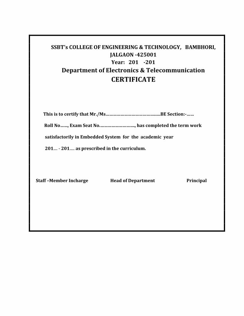
SSBT’s COLLEGE OF ENGINEERING & TECHNOLOGY, BAMBHORI,
JALGAON -425001
Year: 201 -201
Department of Electronics & Telecommunication
CERTIFICATE
This is to certify that Mr./Ms…………………………………......BE Section:-……
Roll No……, Exam Seat No.………………………., has completed the term work
satisfactorily in Embedded System for the academic year 201.... - 201..... as prescribed in the curriculum.
Staff –Member Incharge Head of Department Principal

Department Electronics & Telecommunication Engineering
List of Experiments
INDEX Embedded System
Sr.
No
Name of Experiment Page
No.
Date
of
Performance
Date
of
Completion
Grade Signature
1 To study the Basics of
Embedded System.
2 Writing a Basic C-
programs for I/O
operation
3 Writing Basic C-
programs for interfacing
Seven Segment Display
with ARM-7
4 Write a program for
External Interrupts.
5 Write Basic C-programs to
interface LCD
6 Write a Program to interface
keypad and LCD.
7 Write a program to
interface Stepper Motor
with ARM-7.
8 Write a Program to
implement a context
switching using RTOS
Grades:
A – Excellent, B – Good, C – Average, P - Poor

SSBT’s College of Engineering & Technology, Bambhori, Jalgaon
Department of Electronics & Telecommunication Engineering
Name of Student: Roll No.:
Experiment No. DOP: DOC:
___________________________________________________________________________
___________________________________________________________________________
Embedded System (Lab). BE (E&TC)
Page No. 1
Experiment No:- 1
Title: To study the Basics of Embedded System.
1. Define Embedded System. What are the components of embedded system? An Embedded system is one that has computer hardware with software
embedded in it as one of its most important component.
The three main components of an embedded system are
1.Hardware
2. Main application software
3.RTOS
2. In what ways CISC and RISC processors differ?
CISC RISC
It provides number of addressing modes It provides very few addressing modes
It has a miocroprogrammed unit with a control memory
It has a hardwired unit without a control memory
An easy compiler design Complex compiler design
Provide precise and intensive calculations slower than a RISC
Provide precise and intensive calculations faster than a CISC
3. Define system on chip(SOC) with an example Embedded systems are being designed on a single silicon chip called system on chip. SOC is a new design innovation for embedded system
Eg. Mobile phone.
4. Give any two uses of VLSI designed circuits
A VLSI chip can embed IPs for the specific application besides the ASIP or a GPP core.A system on a VLSI chip that has all of needed analog as well as digital
circuits. Eg. Mobile phone.
5. List the important considerations when selecting a processor.
Instruction set
Maximum bits in an operand
Clock frequency
Processor ability

SSBT’s College of Engineering & Technology, Bambhori, Jalgaon
Department of Electronics & Telecommunication Engineering
Name of Student: Roll No.:
Experiment No. DOP: DOC:
___________________________________________________________________________
___________________________________________________________________________
Embedded System (Lab). BE (E&TC)
Page No. 2
6. What are the types of embedded system?
Small scale embedded systems
Medium scale embedded systems
Sophisticated embedded systems
7. Classify the processors in embedded system? i. General purpose processor
Microprocessor
Microcontroller
Embedded processor
Digital signal processor
Media processor
ii. Application specific system processor
iii. Multiprocessor system using GPP and ASSP
iv. GPP core or ASIP core integrated into either an ASIC or a VLSI
circuit or an FPGA core integrated with processor unit in a VLSI
chip.
8. What are the important embedded processor chips?
ARM 7 and ARM 9
i 960
AMD 29050
9. Name some DSP used in embedded systems?
TMS320Cxx
SHARC
5600xx
10. Name some of the hardware parts of embedded systems?
Power source
Clock oscillator circuit
Timers
Memory units
DAC and ADC
LCD and LED displays
Keyboard/Keypad
SSBT’s College of Engineering & Technology, Bambhori, Jalgaon
Department of Electronics & Telecommunication Engineering
Name of Student: Roll No.:
Experiment No. DOP: DOC:
___________________________________________________________________________
___________________________________________________________________________
Embedded System (Lab). BE (E&TC)
Page No. 3
11. What are the various types of memory in embedded systems?
RAM(internal External)
ROM/PROM/EEPROM/Flash
Cache memory
12. What are the points to be considered while connecting power supply rails with
embedded system?
A processor may have more than two pins of Vdd and Vss
Supply should separately power the external I/O driving ports, timers, and clock
and reset circuits.
From the supply there should be separate interconnections for pairs of Vdd and Vss pins
analog ground analog reference and analog input voltage lines.
13. What are the program layers in the embedded C software?
Preprocessor commands
Main functions
ISR
Tasks
Kernal and Schedular
Library functions
14. List out the uses of RTC?
Schedulers
Real time programming
To obtain the timing and counting needs of the system
To obtain Software controlled delays and time outs.
15. What is watch dog timer? Watch dog timer is a timing device that resets after a predefined timeout.
16. Define a System. A system is a arrangement in which all units assemble and work together
according to a fixed plan or a program
17. What are the two essential units of a processor on a embedded system?
Program Flow control Unit
Execution Unit
SSBT’s College of Engineering & Technology, Bambhori, Jalgaon
Department of Electronics & Telecommunication Engineering
Name of Student: Roll No.:
Experiment No. DOP: DOC:
___________________________________________________________________________
___________________________________________________________________________
Embedded System (Lab). BE (E&TC)
Page No. 4
18. What does the execution unit of a processor in a embedded system do? The EU includes the ALU and also the circuits that execute instructions
for a program control task. The EU has circuits that implement the instructions
pertaining to data transfer operations and data conversion from one form to another.
19. Give examples for general purpose processor.
Microcontroller
Microprocessor
20. Define microprocessor.
A microprocessor is a single VLSI chip that has a CPU and may also have some other units for example floating point processing arithmetic unit pipelining and
super scaling units for faster processing of instruction.
21. When is Application Specific System processors (ASSPs) used in an
embedded system? An ASSP is used as an additional processing unit for running the
application specific tasks in place of processing using embedded software.
23. Define ROM image. Final stage software is also called as ROM image .The final implement
able software for a product embeds in the ROM as an image at a frame. Bytes at each
address must be defined for creating the image.
24. Define device driver.
A device driver is a software for controlling, receiving and sending byte or a stream of bytes from or to a device.
25. Name some of the software’s used for the detailed designing of an
embedded system.
Final machine implement able software for a product
Assembly language
High level language
Machine codes
Software for device drivers and device management.

SSBT’s College of Engineering & Technology, Bambhori, Jalgaon
Department of Electronics & Telecommunication Engineering
Name of Student: Roll No.:
Experiment No. DOP: DOC:
___________________________________________________________________________
___________________________________________________________________________
Embedded System (Lab). BE (E&TC)
Page No. 5
26. What are the various models used in the design of a embedded system?
Finite state machine
Petri net
Control and dataflow graph
Activity diagram based UML model
Synchronous data flow graph
Timed Petri net and extended predicate/transition net
Multithreaded graph
27. Give some examples for small scale embedded systems.
ACVM
Stepper motor controllers for a robotic system
Washing or cooking system
Multitasking toys 28. Give some examples for medium scale embedded systems
Router, a hub and a gateway
Entertainment systems
Banking systems
Signal tracking systems
29. Give some examples for sophisticated embedded systems
Embedded system for wireless LAN
Embedded systems for real time video
Security products
ES for s[pace lifeboat.
Devices and Buses for Devices Network
1. Differentiate synchronous communication and iso-synchronous communication.
Synchronous communication
When a byte or a frame of the data is received or transmitted at constant
time intervals with uniform phase difference, the communication is called synchronous
communication.
iso-synchronous communication
iso-synchronous communication is a special case when the maximum time
interval can be varied.

SSBT’s College of Engineering & Technology, Bambhori, Jalgaon
Department of Electronics & Telecommunication Engineering
Name of Student: Roll No.:
Experiment No. DOP: DOC:
___________________________________________________________________________
___________________________________________________________________________
Embedded System (Lab). BE (E&TC)
Page No. 6
2. What are the two characteristics of synchronous communication?
Bytes maintain a constant phase difference
The clock is not always implicit to the synchronous data receiver.
3. What are the three ways of communication for a device?
iso-synchronous communication
synchronous communication
Asynchronous communication
4. Expand a) SPI b) SCI
SPI—serial Peripheral Interface SCI—Serial Communication Interface
5. Define software timer. This is software that executes and increases or decreases a count variable on an
interrupt from a timer output or form a real time clock interrupt. A software timer can
also generate interrupt on overflow of count value or on finishing value of the count
variable.
6. What is I2C?
I2C is a serial bus for interconnecting ICs .It has a start bit and a stop bit like an UART. It has seven fields for start,7 bit address, defining a read or a write, defining byte as
acknowledging byte, data byte, NACK and end.
5. What are the bits in I2C corresponding to?
It has seven fields for start,7 bit address, defining a read or a write, defining byte as acknowledging byte, data byte, NACK and end
6. What is a CAN bus? Where is it used?
CAN is a serial bus for interconnecting a central Control network. It is mostly used in automobiles. It has fields for bus arbitration bits, control bits for address and data
length data bits, CRC check bits, acknowledgement bits and ending bits.
7. What is USB? Where is it used? USB is a serial bus for interconnecting a system. It attaches and detaches a device
from the network. It uses a root hub. Nodes containing the devices can be organized like a
tree structure. It is mostly used in networking the IO devices like scanner in a computer
system.

SSBT’s College of Engineering & Technology, Bambhori, Jalgaon
Department of Electronics & Telecommunication Engineering
Name of Student: Roll No.:
Experiment No. DOP: DOC:
___________________________________________________________________________
___________________________________________________________________________
Embedded System (Lab). BE (E&TC)
Page No. 7
8. What are the features of the USB protocol? A device can be attached, configured and used, reset, reconfigured and used, share
the bandwidth with other devices, detached and reattached.
9. Explain briefly about PCI and PCI/X buses.
PCI and PCI/X buses are independent from the IBM architecture .PCI/X is an extension of PCI and support 64/100 MHZ transfers. Lately, new versions have been
introduced for the PCI bus architecture.
10. Why are SPCI parallel buses important?
SPCI serial buses are important for distributed devices. The latest high speed sophisticated systems use new sophisticated buses.
11. What is meant by UART?
UART stands for universal Asynchronous Receiver/Transmitter.
UART is a hardware component for translating the data between
parallel and serial interfaces.
UART does convert bytes of data to and from asynchronous start stop bit.
UART is normally used in MODEM.
12. What does UART contain?
A clock generator.
Input and Output shart Registers
Buffers.
Transmitter/Receiver control.
13. What is meant by HDLC?
HDLC stands for “High Level Data Link Control”.
HDLC is a bit oriented protocol.
HDLC is a synchronous data Link layer.
14. Name the HDLC’s frame structure?
Flag Address Control Data FCS Flag

SSBT’s College of Engineering & Technology, Bambhori, Jalgaon
Department of Electronics & Telecommunication Engineering
Name of Student: Roll No.:
Experiment No. DOP: DOC:
___________________________________________________________________________
___________________________________________________________________________
Embedded System (Lab). BE (E&TC)
Page No. 8
List out the states of timer? There are eleven states as follows
Reset state
Idle state
Present state
Over flow state
Over run state
Running state
Reset enabled state / disabled
Finished state
Load enabled / disabled
Auto reload enabled / disabled
Service routine execution enabled / disabled
15. Name some control bit of timer?
Timer Enable
Timer start
Up count Enable
Timer Interrupt Enable
16. What is meant by status flag?
Status flag is the hardware signal to be set when the timer reaches zeros.
17. List out some applications of timer devices?
Real Time clock
Watchdog timer
Input pulse counting
TDM
Scheduling of various tasks
18. State the special features on I2C?
Low cost
Easy implementation
Moderate speed (upto 100 kbps).
SSBT’s College of Engineering & Technology, Bambhori, Jalgaon
Department of Electronics & Telecommunication Engineering
Name of Student: Roll No.:
Experiment No. DOP: DOC:
___________________________________________________________________________
___________________________________________________________________________
Embedded System (Lab). BE (E&TC)
Page No. 9
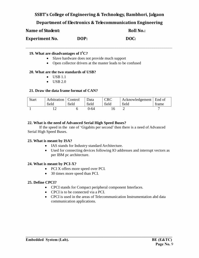
19. What are disadvantages of I2C?
Slave hardware does not provide much support
Open collector drivers at the master leads to be confused
20. What are the two standards of USB?
USB 1.1
USB 2.0
21. Draw the data frame format of CAN?
Start Arbitration
field Control field
Data field
CRC field
Acknowledgement field
End of frame
1 12 6 0-64 16 2 7
22. What is the need of Advanced Serial High Speed Buses? If the speed in the rate of ‘Gigabits per second’ then there is a need of Advanced
Serial High Speed Buses.
23. What is meant by ISA?
IAS stands for Industry standard Architecture.
Used for connecting devices following IO addresses and interrupt vectors as
per IBM pc architecture.
24. What is meant by PCI-X?
PCI X offers more speed over PCI.
30 times more speed than PCI.
25. Define CPCI?
CPCI stands for Compact peripheral component Interfaces.
CPCI is to be connected via a PCI.
CPCI is used in the areas of Telecommunication Instrumentation abd data
communication applications.

SSBT’s College of Engineering & Technology, Bambhori, Jalgaon
Department of Electronics & Telecommunication Engineering
Name of Student: Roll No.:
Experiment No. DOP: DOC:
___________________________________________________________________________
___________________________________________________________________________
Embedded System (Lab). BE (E&TC)
Page No. 10
26. Define half-duplex communication. Transmission occurs in both the direction, but not simultaneously.
27. Define full duplex communication.
Transmission occurs in both the direction, simultaneously
28. Define Real Time Clock (RTC)?
Real time clock is a clock which once the system stats does not stop and cant be reset and its count value can’t be reloaded.
29. Define Time-out or Time Overflow?
A state in which the number of count inputs exceeded the last acquirable value and on reaching that state, an interrupt can be generated.
30. Why do we need at least one timer in an ES?
The embedded system needs at least on timer device. It is used as a system clock.
Programming Concepts and Embedding Programming in C,C++
1. State some advantages of Assembly language?
It gives a precise control of the processor internal devices and full use of
processor specific features in its instruction set and its addressing modes.
The machine codes are compact.
With the help of assembly language the basic concepts could be easily
studied.
Memory required for the system is less.
Minimum assembly languages instruction only needed for device drivers.
2. Write the advantages of high level language?
Standard library functions
Modular programming approach
Bottom up design
Top down design
Data types

SSBT’s College of Engineering & Technology, Bambhori, Jalgaon
Department of Electronics & Telecommunication Engineering
Name of Student: Roll No.:
Experiment No. DOP: DOC:
___________________________________________________________________________
___________________________________________________________________________
Embedded System (Lab). BE (E&TC)
Page No. 11
Type checking
Control structures
Portability
3. What is the most important feature in C that makes it a popular HLL for an
embedded system?
Inline assembly
Readily available modules and library functions.
4. Define In-line assembly
C is a language between low and high level language. Inserting the assembly language codes in between is called in line assembly.
5. Distinguish the interpreter and compiler?
Compiler Interpreter
1. Translation by the whole at a time. Translation goes by line to line.
2. Faster operation. Slower operation comparatively.
3. Error less program helps easier work of compilation.
There is no compilation stage.
6. .List out some ‘Include’ header files used in ‘C’ language in embedded system?
#include<vxwork.h>
#include<semlib.h>
#include<tasklib.h>
#include<syslib.h>
7. What is a Preprocessor Directive? Program statements and directives for the compiler before the main function to
define global variable, global macro, new data type and global constants.
8. Differentiate macros and functions
Macros and functions are used in C programs. Functions are used when the requirement is that the codes should be compiled once only. However on calling a
function the processor has to save the context and on return restore the context. Further a
function may return nothing or an integer or any primitive or reference type of data.
Macros are used when short functional codes are to be inserted in number of places of
functions.
SSBT’s College of Engineering & Technology, Bambhori, Jalgaon
Department of Electronics & Telecommunication Engineering
Name of Student: Roll No.:
Experiment No. DOP: DOC:
___________________________________________________________________________
___________________________________________________________________________
Embedded System (Lab). BE (E&TC)
Page No. 12
9. List the uses of Queues?
Print buffer
Image frames in a sequence
Frames on a network
10. What is list? Give two examples of list data structure.
Contain nodes (element).Each element has a pointer to its next element. Only the first element is identifiable and it is done by list top pointer. No other element is
identifiable and hence is not accessible directly.
A series of tasks which are active.
Menu that point to a sub menu.
11. What is tree? Give an example
There is a root element It has two are more branches each having a daughter element. Each daughter element has two or more daughter elements. The last one does
not have daughters.
Directory
12. Why do you use infinite loop in embedded system?
Infinite loop is used in embedded system in order to make the main program to execute continuously with out having a halt state since an exit from the loop will make
the system hardware redundant.
13. Define NULL pointers
When a pointer points to NULL it means there is no reference to the memory. A memory occupied by an element or object or data structure can be freed by pointing it to the NULL.
14. What are the advantages of reentrant functions?
Reentrant function is usable by several task and routines synchronously.
15. What are the conditions that a reentrant functions must satisfy?
All the arguments pass the values and none of the argument is a pointer, whenever a
calling function calls that function.
When an operation is not atomic that function should not operate on any variable which
is declared outside the function or which an interrupt service routine uses or which is a
global variable but passed by reference and not passed by value as an argument in to the
function.

SSBT’s College of Engineering & Technology, Bambhori, Jalgaon
Department of Electronics & Telecommunication Engineering
Name of Student: Roll No.:
Experiment No. DOP: DOC:
___________________________________________________________________________
___________________________________________________________________________
Embedded System (Lab). BE (E&TC)
Page No. 13
Reentrant function doesn’t call any other function that is not itself re-entrant.
16. What are the advantages of building ISR queues?
Multiple function pointers are queued during ISRs. Each ISR is designed with short set of codes. It doesn’t execute any unessential codes with in the ISR.
17. State the features of OOPS?
Since program can be divided into objects, large, medium and small projects can be
done easily.
Data security may be maintained.
Inclusion of new data and functions are easily done.
User defined data types can be easily constructed.
18. What are the Basic Concepts of OOPS?
Objects
Classes
Data encapsulation
Data abstraction
Single inheritance
Multiple inheritance
Polymorphism
Dynamic binding
Message passing
19. What are the disadvantages of C++? Program codes become lengthy when certain features of the standard C++ are
used. Example for these features includes.
Template
Multiple inheritance
Exceptional handling
Virtual base class
Classes for I/O streams.
20. What is cross compiler?
Cross compiler is a compiler which runs on the host system and produce object codes for target system.

SSBT’s College of Engineering & Technology, Bambhori, Jalgaon
Department of Electronics & Telecommunication Engineering
Name of Student: Roll No.:
Experiment No. DOP: DOC:
___________________________________________________________________________
___________________________________________________________________________
Embedded System (Lab). BE (E&TC)
Page No. 14
21. What is meant by optimization of memory? Certain steps changed to reduce the need for memory and having a compact code.
It reduces the total size of the memory needed. It also reduces the total number of CPU
cycles, and thus total energy requirements.
Real time Operating Systems – Part -1
1. Name the important terms of RTOS?
Task State
Scheduler
Shared data
Reentrancy
2. Define process.
Process is a computational unit that processes on a CPU under the control of a scheduling kernel of an OS. It has a process structure, called Process control block. A
process defines a sequentially executing program and its state.
3. What is meant by PCB?
Process Control Block’ is abbreviated as PCB. PCB is a data structure which contains all the information and components regarding with the process.
4. Define task and Task state.
A task is a set of computations or actions that processes on a CPU under the control of a scheduling kernel. It also has a process control structure called a task control
block that saves at the memory. It has a unique ID. It has states in the system as follows:
idle, ready, running, blocked and finished
5. Define Task Control Block (TCB)
A memory block that holds information of program counter, memory map, the signal dispatch table, signal mask, task ID, CPU state and a kernel stack.
SSBT’s College of Engineering & Technology, Bambhori, Jalgaon
Department of Electronics & Telecommunication Engineering
Name of Student: Roll No.:
Experiment No. DOP: DOC:
___________________________________________________________________________
___________________________________________________________________________
Embedded System (Lab). BE (E&TC)
Page No. 15
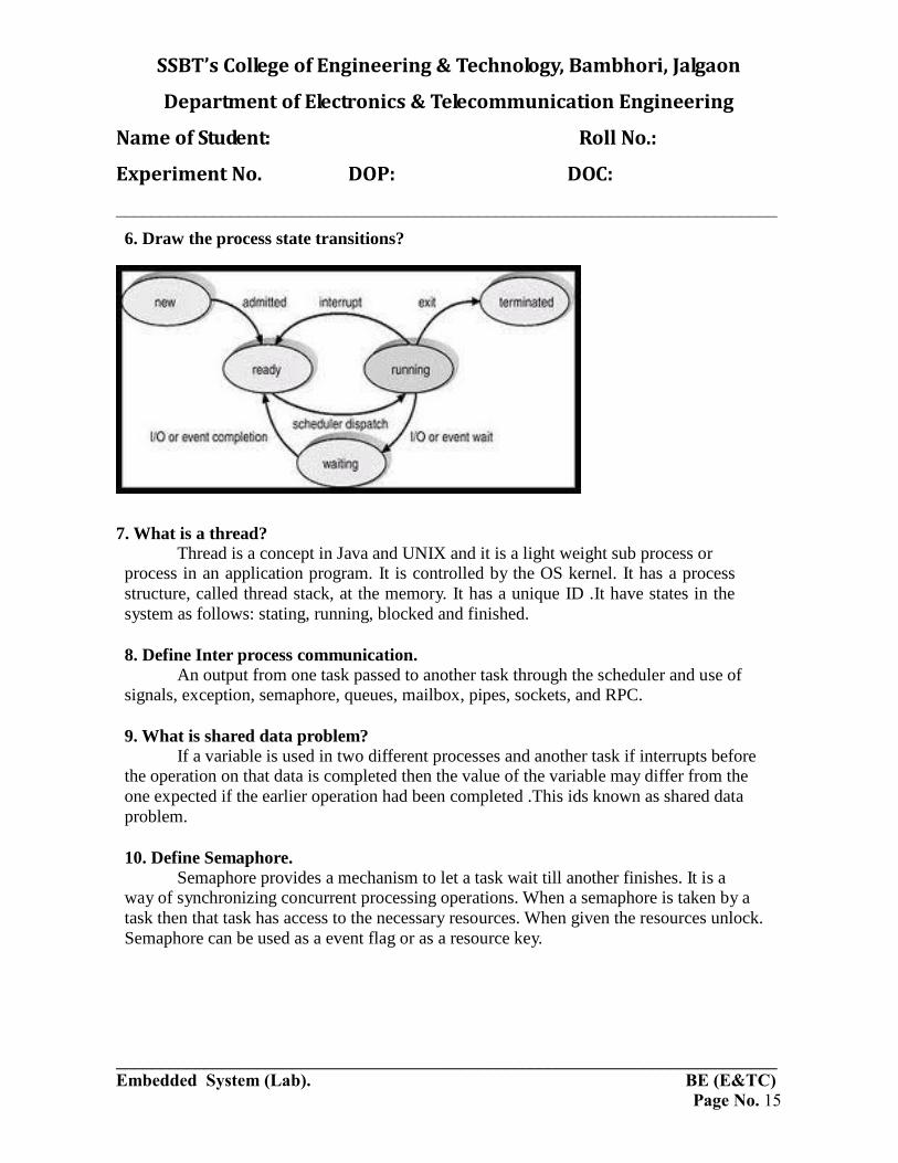
6. Draw the process state transitions?
7. What is a thread? Thread is a concept in Java and UNIX and it is a light weight sub process or
process in an application program. It is controlled by the OS kernel. It has a process
structure, called thread stack, at the memory. It has a unique ID .It have states in the
system as follows: stating, running, blocked and finished.
8. Define Inter process communication.
An output from one task passed to another task through the scheduler and use of signals, exception, semaphore, queues, mailbox, pipes, sockets, and RPC.
9. What is shared data problem?
If a variable is used in two different processes and another task if interrupts before the operation on that data is completed then the value of the variable may differ from the
one expected if the earlier operation had been completed .This ids known as shared data
problem.
10. Define Semaphore.
Semaphore provides a mechanism to let a task wait till another finishes. It is a way of synchronizing concurrent processing operations. When a semaphore is taken by a
task then that task has access to the necessary resources. When given the resources unlock.
Semaphore can be used as a event flag or as a resource key.

SSBT’s College of Engineering & Technology, Bambhori, Jalgaon
Department of Electronics & Telecommunication Engineering
Name of Student: Roll No.:
Experiment No. DOP: DOC:
___________________________________________________________________________
___________________________________________________________________________
Embedded System (Lab). BE (E&TC)
Page No. 16
11. Define Mutex. A phenomenon for solving the shared data problem is known as
semaphore. Mutex is a semaphore that gives at an instance two tasks mutually exclusive
access to resources.
12. Differentiate counting semaphore and binary semaphore. Binary semaphore
When the value of binary semaphore is one it is assumed that no task has taken it
and that it has been released. When the value is 0 it is assumed that it has been taken.
Counting semaphore
Counting semaphore is a semaphore which can be taken and given number of
times. Counting semaphores are unsigned integers.
13. What is Priority inversion?
A problem in which a low priority task inadvertently does not release the process for a higher priority task.
14. What is Deadlock situation?
A set of processes or threads is deadlocked when each process or thread is waiting for a resource to be freed which is controlled by another process.
15. Define Message Queue.
A task sending the multiple FIFO or priority messages into a queue for use by another task using queue messages as an input.
16. Define Mailbox and Pipe. A message or message pointer from a task that is addressed to another task.
17. Define Socket.
It provides the logical link using a protocol between the tasks in a client server or peer to peer environment.
18. Define Remote Procedure Call.
A method used for connecting two remotely placed methods by using a protocol. Both systems work in the peer to peer communication mode and not in the client server
mode.

SSBT’s College of Engineering & Technology, Bambhori, Jalgaon
Department of Electronics & Telecommunication Engineering
Name of Student: Roll No.:
Experiment No. DOP: DOC:
___________________________________________________________________________
___________________________________________________________________________
Embedded System (Lab). BE (E&TC)
Page No. 17
19. What are the goals of RTOS?
Facilitating easy sharing of resources
Facilitating easy implantation of the application software
Maximizing system performance
Providing management and organization functions for the devices and
files and file like devices.
Portability
Interoperability
Providing common set of interfaces.
20. What is RTOS?
An RTOS is an OS for response time controlled and event controlled processes. RTOS is an OS for embedded systems, as these have real time programming issues to
solve.
21. List the functions of a kernel.
Process management
Process creation to deletion
Processing resource requests
Scheduling
IPC
Memory management
I/O management
Device management
22. What are the two methods by which a running requests resources?
Message
System call
23. What are the functions of device manager?
Device detection and addition
Device deletion
Device allocation and registration
Detaching and deregistration
Device sharing

SSBT’s College of Engineering & Technology, Bambhori, Jalgaon
Department of Electronics & Telecommunication Engineering
Name of Student: Roll No.:
Experiment No. DOP: DOC:
___________________________________________________________________________
___________________________________________________________________________
Embedded System (Lab). BE (E&TC)
Page No. 18
24. List the set of OS command functions for a device
Create and open
Write
Read
Close and delete
25. List the set of command functions of POSIX file system
Open Write
Read
Lseek
close
26. What are the three methods by which an RTOS responds to a hardware source
call on interrupt?
Direct call to ISR by an interrupt source
Direct call to RTOS by an interrupt source and temporary suspension of a
scheduled task.
Direct call to RTOS by an interrupt source and scheduling of tasks as well as
ISRs by the RTOS.
Providing management functions for the processes, memory, and I/Os and
for other functions for which i9t is designed.
Real time Operating Systems – Part -2
1. Name any two important RTOS.
MUCOS
VxWorks
2. Write short notes on Vxworks?
Vxworks is a popular Real-time multi-tasking operating system for embedded
microprocessors and systems.
Vxworks can run on many target processors.
It is a UNIX like Real time operating system.
More Reliable
More faster
3. What is meant by well tested and debugged RTOS?
An RTOS which is thoroughly tested and debugged in a number of situations.

SSBT’s College of Engineering & Technology, Bambhori, Jalgaon
Department of Electronics & Telecommunication Engineering
Name of Student: Roll No.:
Experiment No. DOP: DOC:
___________________________________________________________________________
___________________________________________________________________________
Embedded System (Lab). BE (E&TC)
Page No. 19
4. What is sophisticated multitasking embedded system? A system that has multitasking needs with multiple features and in which the
tasks have deadlines that must be adhered to.
5. What are the features of UC/OS II?
Preemptive
Portable
Scalable
Multitasking
6. What is MICRO C/OS II?
It stands for micro-controller operating system(UC/OS II).
It is a real time kernel
The other names of MICROC/OS II are MUCOS and UCOS.
The codes are in ‘C’ and Assembly language.
7. What are the real time system level functions in UC/OS II? State some?
1 Initiating the OS before starting the use of the RTOS fuctions. 2 Starting the use of RTOS multi-tasking functions and running the states.
3 Starting the use of RTOS system clock.
8. Write the interrupt handling functions?
int connect ( ) is the function for handling the Interrupt. int Lock ( ) -> Disable Interrupts.
int unlock( ) -> Enable functions.
9. Write down the seven task priorities in embedded 'C++'?. define Task _Read ports priority define Task _Excess Refund priority
define Task _Deliver priority
define Task _Refund priority
define Task _Collect priority
define Task _Display priority
define Task _Time Date Display priority

SSBT’s College of Engineering & Technology, Bambhori, Jalgaon
Department of Electronics & Telecommunication Engineering
Name of Student: Roll No.:
Experiment No. DOP: DOC:
___________________________________________________________________________
___________________________________________________________________________
Embedded System (Lab). BE (E&TC)
Page No. 20
10. Name any two mailbox related functions.
OS_Event *OSMboxCreate(void *mboxMsg)
Void *OSMboxAccept(OS_EVENT *mboxMsg)
11. Name any two queue related functions for the inter task communications.
OS_Event OSQCreate(void **QTop,unsigned byte qSize)
Unsigned byte OSQPostFront(OS_EVENT *QMsgPointer,void *qmsg)
12. How is Vx Works TCB helpful for tasks?
Provide control information for the OS that includes priority, stack size,
state and options.
CPU context of the task that includes PC, SP, CPU registers and task
variables.
13. What are the various features of Vx Works?
VxWorks is a scalable OS
RTOS hierarchy includes timers, signals, TCP/IP sockets, queuing
functions library, Berkeley ports and sockets, pipes, UNIX compatible
loader, language interpreter, shell, debugging tools, linking loader for
UNIX.
14. What is an active task in the context of Vx Works?
Active task means that it is in one of the three states, ready, running, or waiting.
15. What are the task service functions supported by Vx Works?
taskSpawn()
taskResume()
taskSuspand()
taskDelay()
taskSuspand()
taskInit()
exit()
taskDelete()
16. Name any four interrupt service functions supported by Vx Works?
intLock()
intVectSet()
intVectGet()
intContext()

SSBT’s College of Engineering & Technology, Bambhori, Jalgaon
Department of Electronics & Telecommunication Engineering
Name of Student: Roll No.:
Experiment No. DOP: DOC:
___________________________________________________________________________
___________________________________________________________________________
Embedded System (Lab). BE (E&TC)
Page No. 21
17. Name some of the inter process communication function.
semBCreate()
semMCreate()
semCCreate()
semTake()
semDelete()
18. Name some of the inter process communication function used for messaging.
msgQCreate()
msgQDelete()
msgQSend()
msgQReceive()
19. What are Vx Works pipes? VxWorks pipes are thec queues that can be opened and closed like a pipe.pipes
are like virtual IO devices that store the messages as FIFO.
20. What are the different types of scheduling supported by Vx Works?
Preemptive priority
Time slicing
21. What are the task service functions supported by MUCOS?
Void OSInit (void)
Void OSStart(void)
voidOSTickInit(void)
void OSIntEnter(void)
void OSIntExit(void)
22. What are the semaphores related functions supported by MUCOS?
OS_Event OSSemCreate(unsigned short sem val)
Void OSSemPend(OS_Event *eventPointer,unsigned short
timeout,unsigned byte *SemErrPointer)
unsigned short OSSemAccept(OS_Event*eventPointer)
unsigned short OSSemPost(OS_Event*eventPointer)

SSBT’s College of Engineering & Technology, Bambhori, Jalgaon
Department of Electronics & Telecommunication Engineering
Name of Student: Roll No.:
Experiment No. DOP: DOC:
___________________________________________________________________________
___________________________________________________________________________
Embedded System (Lab). BE (E&TC)
Page No. 22
1. Project Creation / Compilation / Downloading STEPS:
Double click on the icon Triton available on your Desktop.
Select the workspace by creating a folder or also can select the default
Workspace.
Create C or C++ project by clicking Project New C Project /C++Project.
Enter a name for the project. In the Project name field, type the name ofproject.
Do not use spaces
or special characters in the project name (for example, "ABC").
Select appropriate Target i.e ARM.
Select appropriate Variant LPC2138 /LPC2148 /LPC2129 from list as required for
building project.
Select appropriate Operating System, here we would select none as the operating
system.
Select Port from list as per your target board i.e COM1.
Select Baud Rate from dropdown list i.e 38400.
And let the rest of the options be default, and then click Next.
Select the type of project that you want to build. By default Project Type is
Executable (Gnu).
Debug - Project can be debugged on target board using Serial, Odyssey JTAG
and Ethernet
Release - Project is run on Target board without debugging.
Click Finish when you are done.
You should now see the new project (ABC) in the C/C++ Projects view.
In Triton IDE new project created will have template files. for eg – ABC_main.c
and ABC_start.s
SSBT’s College of Engineering & Technology, Bambhori, Jalgaon
Department of Electronics & Telecommunication Engineering
Name of Student: Roll No.:
Experiment No. DOP: DOC:
___________________________________________________________________________
___________________________________________________________________________
Embedded System (Lab). BE (E&TC)
Page No. 23
Properties file is also created which shows properties of project.
Enter the code in the ABC_main .c file. You can double click the ABC_main.c
tab in the Editor view to expand the view.
You will notice an asterisk in front of the file name on the tab in the Editor
view.The asterisk indicates that the file has changed but has not been saved.
Now save the ABC_main .c file by clicking File Save.
In Triton IDE you can build project in two modes :--
1. Debug mode - Builds project with debugging
2. Release mode - Builds project without debugging
To build project in release mode:
Select release mode by right clicking on project and click Active Build
Configuration Release.
Right click on the project folder, and select the option BUILD.
Navigate to the C/C++ Projects view and expand the Release folder created
when you build project in Release mode.
Here, ABC.hex file is created which is to be downloaded on target board and
executed.
Connect the Hardware Board with the serial connector and power supply
provided.
Switch on the Hardware Board, and put the switch in ISP Mode for the program to
be downloaded.
Right click on the ABC.hex file and download the executable code on to
theBoard.
Once, the program is downloaded, shift the mode from ISP to RUN and reset the
Board to verify the output.
SSBT’s College of Engineering & Technology, Bambhori, Jalgaon
Department of Electronics & Telecommunication Engineering
Name of Student: Roll No.:
Experiment No. DOP: DOC:
___________________________________________________________________________
___________________________________________________________________________
Embedded System (Lab). BE (E&TC)
Page No. 24
Experiment No:- 2
Title: Write a Program for I/O operations using ARM-7 Processor.
Aim: Interface ARM 7 with 8 LED’s and write embedded-C program to Blink LED with
interval.
Program Description:
This program demonstrates blinking of LED using(General processor input
output) GPIO.
Pin Assignment :LED Display Interface
Sr.No Signal Description
1 Pin 45 (P0.15) L8
2 Pin 46 (P0.16) L7
3 Pin 47 (P0.17) L6
4 Pin 53 (P0.18) L5
5 Pin 54 (P0.19) L4
6 Pin 55 (P0.20) L3
7 Pin 1 (P0.21) L2
8 Pin 2 (P0.22) L1
Output:
LED blinks continuously.
Part List :
1. OASIS ARM7( TITAN) BOARD
2. RS232 Serial cable
3. 9 Volt DC Power Supply
4. Triton IDE

SSBT’s College of Engineering & Technology, Bambhori, Jalgaon
Department of Electronics & Telecommunication Engineering
Name of Student: Roll No.:
Experiment No. DOP: DOC:
___________________________________________________________________________
___________________________________________________________________________
Embedded System (Lab). BE (E&TC)
Page No. 25
Procedure:
1. Connect 9 V DC Power supply to the OASIS TITAN Board.
2. Connect the board with COM port of PC using the serial cable.
3. Generate .hex file using Triton IDE.
4. Download the .hex file.
5. Put the board in RUN mode and observe the output.
Program
#include<LPC21xx.h>
void delay();
int main(void)
{
*IODIR0 = 0x7f8000; // Declare pin are interfaced with ARM7
while(1)
{
*IOPIN0 = 0x550000; // Alternate LED’s are ON / OFF
delay(); // Delay to turn ON LED for same time
*IOPIN0 = 0x2A8000; // Alternate LED’s are OFF / ON
delay();
}
return 0;
}
void delay()
{
unsigned int x=500000; // A value 500000 decide time period.
while( x > 0 )
x--;
}
Conclusion
SSBT’s College of Engineering & Technology, Bambhori, Jalgaon
Department of Electronics & Telecommunication Engineering
Name of Student: Roll No.:
Experiment No. DOP: DOC:
___________________________________________________________________________
___________________________________________________________________________
Embedded System (Lab). BE (E&TC)
Page No. 26
Experiment No:- 3
Title: Writing Basic C-programs for interfacing of Seven Segment Display with
ARM-7 Processor.
Aim: Interface 7 segment display with ARM 7 and write embedded c program
to demonstrate 0-F No’s on 7 segment display with specified interval.
Program Description:
This program demonstrates 0-F digit on Seven Segment Display using ARM 7.
Pin Assignment :
The following table lists details about the 7-Segment Display interface.
Description: 7-segment Display
Sr.No Signal Description
1 Pin 16 (P1.16) ‘a’
2 Pin 12 (P1.17) ‘b’
3 Pin 8 (P1.18) ‘c’
4 Pin 4 (P1.19) ‘d’
5 Pin 48 (P1.20) ‘e’
6 Pin 44 (P1.21) ‘f’
7 Pin 40 (P1.22) ‘g’
8 Pin 36 (P1.23) ‘.’
9 Pin 13 (P0.28) NC
10 Pin 14 (P0.29) NC
11 GND NC
Output:
The 0-F digits are displayed continuously one by one on 7 Segment display after completion
of delay routine.

SSBT’s College of Engineering & Technology, Bambhori, Jalgaon
Department of Electronics & Telecommunication Engineering
Name of Student: Roll No.:
Experiment No. DOP: DOC:
___________________________________________________________________________
___________________________________________________________________________
Embedded System (Lab). BE (E&TC)
Page No. 27
Header Files:
LPC21xx.h, board.h
Part List :
1. OASIS ARM7( TITAN) BOARD
2. RS232 Serial cable
3. 9 Volt DC Power Supply
4. Triton IDE
Procedure:
1. Connect 9 V DC Power supply to the OASIS TITAN Board.
2. Connect the Board with the COM port of the PC using the serial cable.
3. Generate .hex file using Triton IDE.
4. Download the .hex file.
5. Put the board in RUN mode and observe the output.
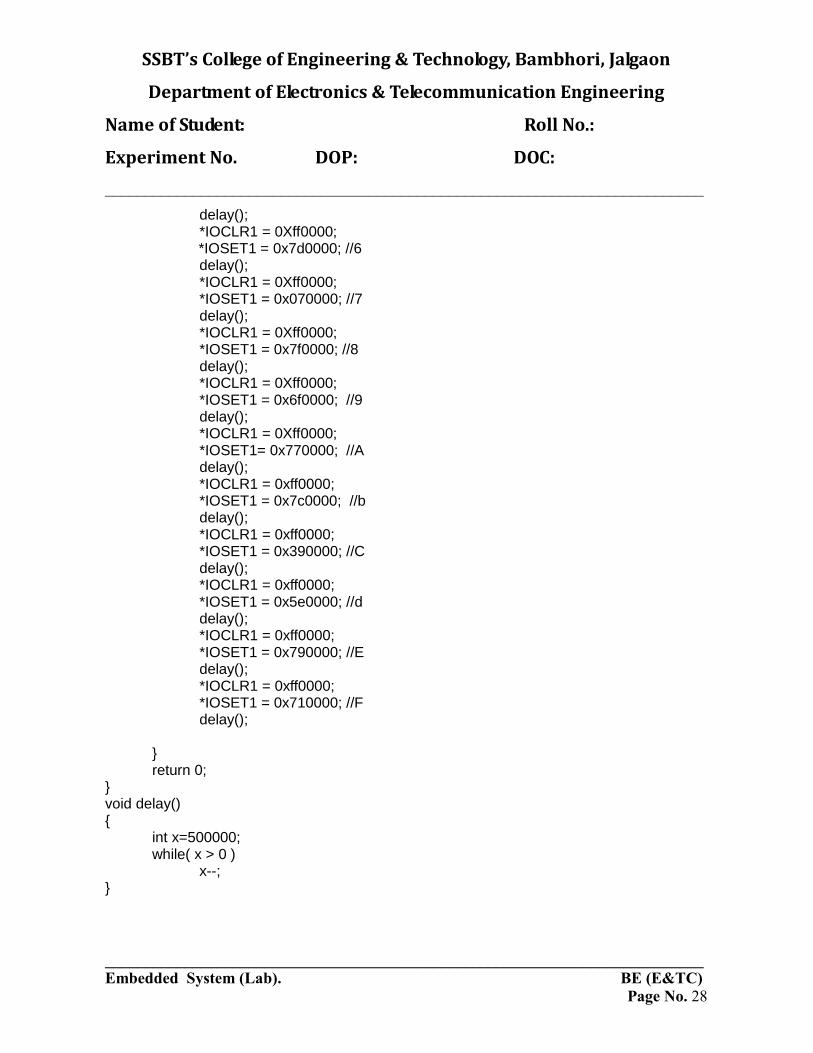
Program #include<LPC21xx.h> void delay(); int main(void) { *IODIR1 = 0XFF0000;// Declare pins are interfaced with ARM 7. while(1) { *IOCLR1 = 0Xff0000; // Clear data from the port pins. *IOSET1 = 0x3f0000; //0 // pass the code of all no. to be display on 7segment delay(); *IOCLR1 = 0Xff0000; *IOSET1 = 0x060000; //1 delay(); *IOCLR1 = 0Xff0000; *IOSET1 = 0x5b0000; //2 delay(); *IOCLR1 = 0Xff0000; *IOSET1 = 0x4f0000; //3 delay(); *IOCLR1 = 0Xff0000; *IOSET1 = 0x660000; //4 delay(); *IOCLR1 = 0Xff0000; *IOSET1 = 0x6d0000; //5
SSBT’s College of Engineering & Technology, Bambhori, Jalgaon
Department of Electronics & Telecommunication Engineering
Name of Student: Roll No.:
Experiment No. DOP: DOC:
___________________________________________________________________________
___________________________________________________________________________
Embedded System (Lab). BE (E&TC)
Page No. 28
delay(); *IOCLR1 = 0Xff0000; *IOSET1 = 0x7d0000; //6 delay(); *IOCLR1 = 0Xff0000; *IOSET1 = 0x070000; //7 delay(); *IOCLR1 = 0Xff0000; *IOSET1 = 0x7f0000; //8 delay(); *IOCLR1 = 0Xff0000; *IOSET1 = 0x6f0000; //9 delay(); *IOCLR1 = 0Xff0000; *IOSET1= 0x770000; //A delay(); *IOCLR1 = 0xff0000; *IOSET1 = 0x7c0000; //b delay(); *IOCLR1 = 0xff0000; *IOSET1 = 0x390000; //C delay(); *IOCLR1 = 0xff0000; *IOSET1 = 0x5e0000; //d delay(); *IOCLR1 = 0xff0000; *IOSET1 = 0x790000; //E delay(); *IOCLR1 = 0xff0000; *IOSET1 = 0x710000; //F delay(); } return 0; } void delay() { int x=500000; while( x > 0 ) x--; }

SSBT’s College of Engineering & Technology, Bambhori, Jalgaon
Department of Electronics & Telecommunication Engineering
Name of Student: Roll No.:
Experiment No. DOP: DOC:
___________________________________________________________________________
___________________________________________________________________________
Embedded System (Lab). BE (E&TC)
Page No. 29
Bit pattern of interface 7 segment.
S. N DP G F E D C B A Code
0 0 0 1 1 1 1 1 1 3FH
1 0 0 0 0 0 1 1 0 06H
2 0 1 0 1 1 0 1 1 5BH
3 0 1 0 0 1 1 1 1 4FH
4 0 1 1 0 0 1 1 0 66H
5 0 1 1 0 1 1 0 1 6DH
6 0 1 1 1 1 1 0 1 7DH
7 0 0 0 0 0 1 1 1 07H
8 0 1 1 1 1 1 1 1 7FH
9 0 1 1 0 1 1 1 1 6FH
A 0 1 1 1 0 1 1 1 77H
B 0 1 1 1 1 1 0 0 7DH
C 0 0 1 1 1 0 0 1 39H
D 0 1 0 1 1 1 1 0 5EH
E 0 1 1 1 1 0 0 1 79H
F 0 1 1 1 0 0 0 1 71H

SSBT’s College of Engineering & Technology, Bambhori, Jalgaon
Department of Electronics & Telecommunication Engineering
Name of Student: Roll No.:
Experiment No. DOP: DOC:
___________________________________________________________________________
___________________________________________________________________________
Embedded System (Lab). BE (E&TC)
Page No. 30
Conclusion

SSBT’s College of Engineering & Technology, Bambhori, Jalgaon
Department of Electronics & Telecommunication Engineering
Name of Student: Roll No.:
Experiment No. DOP: DOC:
___________________________________________________________________________
___________________________________________________________________________
Embedded System (Lab). BE (E&TC)
Page No. 31
Experiment No:- 4
Title: Write a program for External Interrupts .
Aim: Interface a switch with ARM 7 using interrupt .write a C program to monitor interrupt
bit status and execute a routine to display 0-F no. on 7 segment.
Program Description:
This program demonstrates interrupts using on board EXT SWITCH
Pin Assignment :
The following table lists details about the 7-Segment Display interface.
Description: 7-segment Display
Sr.No Signal Description
1 Pin 16 (P1.16) ‘ a’
2 Pin 12 (P1.17) ‘b’
3 Pin 8 (P1.18) ‘c’
4 Pin 4 (P1.19) ‘d’
5 Pin 48 (P1.20) ‘e’
6 Pin 44 (P1.21) ‘f’
7 Pin 40 (P1.22) ‘g’
8 Pin 36 (P1.23) ‘.’
9 Pin 13 (P0.28) NC
10 Pin 14 (P0.29) NC
11 GND NC
Output:
The digit on 7 Segment will glow after getting interrupt.
Header Files:
LPC21xx.h, board.h

SSBT’s College of Engineering & Technology, Bambhori, Jalgaon
Department of Electronics & Telecommunication Engineering
Name of Student: Roll No.:
Experiment No. DOP: DOC:
___________________________________________________________________________
___________________________________________________________________________
Embedded System (Lab). BE (E&TC)
Page No. 32
Part List :
1. OASIS ARM7( TITAN) BOARD
2. RS232 Serial cable
3. 9 Volt DC Power Supply
4. Triton IDE
Procedure:
1. Connect 9 V DC Power supply to the OASIS TITAN Board.
2. Connect the Board with the COM port of the PC using the serial cable.
3. Generate .hex file using Triton IDE.
4. Download the .hex file.
5. Put the board in RUN mode and observe the output.
*****External Interrupt based 7-segment display*****
#include<board.h>
#include<LPC21xx.h>
void ISRHandlerEXTINT3()__attribute__((interrupt("IRQ"))); void delay() { int x=500000; while( x > 0 ) x--; }
void ISRHandlerEXTINT3(void)
{
*EXTINT=0x00000008;
q_printf("External Interrupt\n");
*IODIR1 = 0XFF0000;
*IOCLR1 = 0Xff0000;
delay();
*IOSET1 = 0x3f0000;
delay();
*IOCLR1 = 0Xff0000;
*IOSET1 = 0x060000;
delay();
*IOCLR1 = 0Xff0000;
*IOSET1 = 0x5b0000;
delay();

SSBT’s College of Engineering & Technology, Bambhori, Jalgaon
Department of Electronics & Telecommunication Engineering
Name of Student: Roll No.:
Experiment No. DOP: DOC:
___________________________________________________________________________
___________________________________________________________________________
Embedded System (Lab). BE (E&TC)
Page No. 33
*IOCLR1 = 0Xff0000;
*IOSET1 = 0x4f0000;
delay();
*IOCLR1 = 0Xff0000;
*IOSET1 = 0x660000;
delay();
*IOCLR1 = 0Xff0000;
*IOSET1 = 0x6d0000;
delay();
*IOCLR1 = 0Xff0000;
*IOSET1 = 0x7d0000;
delay();
*IOCLR1 = 0Xff0000;
*IOSET1 = 0x070000;
delay();
*IOCLR1 = 0Xff0000;
*IOSET1 = 0x7f0000;
delay();
*IOCLR1 = 0Xff0000;
*IOSET1 = 0x6f0000;
delay();
*IOCLR1 = 0Xff0000;
*IOSET1 = 0x770000;
delay();
*IOCLR1 = 0xff0000;
*IOSET1 = 0x7c0000;
delay();
*IOCLR1 = 0xff0000;
*IOSET1 = 0x390000;
delay();
*IOCLR1 = 0xff0000;
*IOSET1 = 0x5e0000;
delay();
*IOCLR1 = 0xff0000;
*IOSET1 = 0x790000;
delay();
*IOCLR1 = 0xff0000;
*IOSET1 = 0x710000;

SSBT’s College of Engineering & Technology, Bambhori, Jalgaon
Department of Electronics & Telecommunication Engineering
Name of Student: Roll No.:
Experiment No. DOP: DOC:
___________________________________________________________________________
___________________________________________________________________________
Embedded System (Lab). BE (E&TC)
Page No. 34
delay();
*IOCLR1 = 0xff0000;
*IOSET1 = 0x760000;
delay();
*IOCLR1 = 0xff0000;
*IOSET1 = 0x800000;
delay();
*IOSET1 = 0x000000;
delay();
q_printf("Press the switch again\n");
*VICVectAddr=0 ;
}
void IRQInit()
{
*PINSEL1=0x20000000;
*EXTMODE=0x8;
*VICVectAddr0=(unsigned int)ISRHandlerEXTINT3;
*VICVectCntl0=0x20|0x11;
*VICIntEnable=0x20000 |*VICIntEnable;
}
int main(void)
{
*IODIR0=0x7F8000;
IRQInit();
q_printf("main\n ");
return 0;
}

SSBT’s College of Engineering & Technology, Bambhori, Jalgaon
Department of Electronics & Telecommunication Engineering
Name of Student: Roll No.:
Experiment No. DOP: DOC:
___________________________________________________________________________
___________________________________________________________________________
Embedded System (Lab). BE (E&TC)
Page No. 35
S. N DP G F E D C B A Code
0 0 0 1 1 1 1 1 1 3FH
1 0 0 0 0 0 1 1 0 06H
2 0 1 0 1 1 0 1 1 5BH
3 0 1 0 0 1 1 1 1 4FH
4 0 1 1 0 0 1 1 0 66H
5 0 1 1 0 1 1 0 1 6DH
6 0 1 1 1 1 1 0 1 7DH
7 0 0 0 0 0 1 1 1 07H
8 0 1 1 1 1 1 1 1 7FH
9 0 1 1 0 1 1 1 1 6FH
A 0 1 1 1 0 1 1 1 77H
B 0 1 1 1 1 1 0 0 7DH
C 0 0 1 1 1 0 0 1 39H
D 0 1 0 1 1 1 1 0 5EH
E 0 1 1 1 1 0 0 1 79H
F 0 1 1 1 0 0 0 1 71H
Conclusion

SSBT’s College of Engineering & Technology, Bambhori, Jalgaon
Department of Electronics & Telecommunication Engineering
Name of Student: Roll No.:
Experiment No. DOP: DOC:
___________________________________________________________________________
___________________________________________________________________________
Embedded System (Lab). BE (E&TC)
Page No. 36
Experiment No:- 5
Title: Write Basic C-programs to interface LCD.
Aim: Interface LCD with ARM 7 write a C program to demonstrate a string on LCD screen
Program Description:
This program displays output on LCD
Pin Assignment: LCD display interface
Sr. No. Signal Description
1 Pin 16 (P1.16) Data 0
2 Pin 12 (P1.17) Data 1
3 Pin 8 (P1.18) Data 2
4 Pin 4 (P1.19) Data 3
5 Pin 48 (P1.20) Data 4
6 Pin 44 (P1.21) Data 5
7 Pin 40 (P1.22) Data 6
8 Pin 36 (P1.23) Data 7
9 Pin 13 (P0.28) RS
10 Pin 14 (P0.29) EN
11 GND WR
Output:
'A string' given in code will be displayed on LCD.
Header Files:
LPC21xx.h

SSBT’s College of Engineering & Technology, Bambhori, Jalgaon
Department of Electronics & Telecommunication Engineering
Name of Student: Roll No.:
Experiment No. DOP: DOC:
___________________________________________________________________________
___________________________________________________________________________
Embedded System (Lab). BE (E&TC)
Page No. 37
Part List :
1. OASIS ARM7( TITAN) BOARD
2. RS232 Serial cable
3. 9 Volt DC Power Supply
4. Triton IDE
Procedure:
1. Connect 9 V DC Power supply to the OASIS TITAN Board.
2. Connect the Board with the COM port of the PC using the serial cable.
3. Generate .hex file using Triton IDE.
4. Download the .hex file.
5. Put the board in RUN mode and you can observe the output.
*****Interfacing LCD*****
#include<lpc21xx.h>
void lcddata(int value);
void lcdcmd(int value);
void delay(int itime);
int main()
{
*IODIR1=0x00FF0000;
*IODIR0=0x30000000;
lcdcmd(0x38);
delay(250);
lcdcmd(0x0e);
delay(250);
lcdcmd(0x80);
delay(250);
lcddata('h');
delay(250);
lcddata('e');
delay(250);
lcddata('l');
delay(250);

SSBT’s College of Engineering & Technology, Bambhori, Jalgaon
Department of Electronics & Telecommunication Engineering
Name of Student: Roll No.:
Experiment No. DOP: DOC:
___________________________________________________________________________
___________________________________________________________________________
Embedded System (Lab). BE (E&TC)
Page No. 38
lcddata('l');
delay(250);
lcddata('o');
delay(250);
return 0;
}
void lcdcmd(int value)
{
*IOCLR1=0x00FF0000;
*IOCLR0=0x10000000;
value<<=16;
*IOSET1=value;
*IOCLR0=0x20000000;
delay(250);
*IOSET0=0x20000000;
delay(250);
*IOCLR0=0x20000000;
delay(250);
}
void lcddata(int value)
{
*IOCLR1=0x00FF0000;
*IOSET0=0x10000000;
value<<=16;
*IOSET1=value;
*IOCLR0=0x20000000;
delay(250);
*IOSET0=0x20000000;
delay(250);
*IOCLR0=0x20000000;
delay(250);
}
void delay(int itime)
{
int i;
for(i=0;i<itime;i++);
}

SSBT’s College of Engineering & Technology, Bambhori, Jalgaon
Department of Electronics & Telecommunication Engineering
Name of Student: Roll No.:
Experiment No. DOP: DOC:
___________________________________________________________________________
___________________________________________________________________________
Embedded System (Lab). BE (E&TC)
Page No. 39
Pin No Symbol I/O Description
1 Vss - Ground
2 Vcc +5V
3 Vee Contrast Control
4 RS Input Command/Data Register
5 R/W Input Read/Write Register
6 E Input/Output Enable
7 DB0 Input/Output Not Used in 4-Bit Mode
8 DB1 Input/Output Not Used in 4-Bit Mode
9 DB2 Input/Output Not Used in 4-Bit Mode
10 DB3 Input/Output Not Used in 4-Bit Mode
11 DB4 Input/Output Data Bus in 4-Bit Mode
12 DB5 Input/Output Data Bus in 4-Bit Mode
13 DB6 Input/Output Data Bus in 4-Bit Mode
14 DB7 Input/Output Data Bus in 4-Bit Mode
15 Vcc - For LCD Back Light
16 Vss - For LCD Back Light

SSBT’s College of Engineering & Technology, Bambhori, Jalgaon
Department of Electronics & Telecommunication Engineering
Name of Student: Roll No.:
Experiment No. DOP: DOC:
___________________________________________________________________________
___________________________________________________________________________
Embedded System (Lab). BE (E&TC)
Page No. 40
Conclusion

SSBT’s College of Engineering & Technology, Bambhori, Jalgaon
Department of Electronics & Telecommunication Engineering
Name of Student: Roll No.:
Experiment No. DOP: DOC:
___________________________________________________________________________
___________________________________________________________________________
Embedded System (Lab). BE (E&TC)
Page No. 41
Experiment No:- 6
Title: Write a Program to interface keypad and LCD.
Aim: Interface Keyboard and LCD using standard library function with ARM-7 Write ALP
to demonstrate string and Keycode on LCD when any key is pressed by user.
Program Description:
This program demonstrates LCD using keypad.
Output:
Character will be displayed on LCD as per the pressed key on keyboard.
Header Files:
Board.h
Part List :
1. OASIS ARM7( TITAN) BOARD
2. RS232 Serial cable
3. 9 Volt DC Power Supply
4. Triton IDE
Procedure:
1. Connect 9 V DC Power supply to the OASIS TITAN Board.
2. Connect the Board with the COM port of the PC using the serial cable.
3. Generate .hex file using Triton IDE.
4. Download the .hex file.
5. Put the board in RUN mode.
6. Press any key on on-board Keypad and you can observe the output on LCD.
*****Displaying the key press on LCD*****
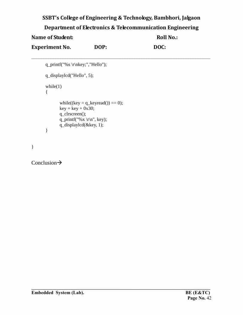
#include <board.h>
int main(void)
{
char key;
q_keyinit(TITAN);
q_lcdinit(TITAN);
SSBT’s College of Engineering & Technology, Bambhori, Jalgaon
Department of Electronics & Telecommunication Engineering
Name of Student: Roll No.:
Experiment No. DOP: DOC:
___________________________________________________________________________
___________________________________________________________________________
Embedded System (Lab). BE (E&TC)
Page No. 42
q_printf("%s \r\nkey;","Hello");
q_displaylcd("Hello", 5);
while(1)
{
while((key = q_keyread()) == 0);
key = key + 0x30;
q_clrscreen();
q_printf("%x \r\n", key);
q_displaylcd(&key, 1);
}
}
Conclusion

SSBT’s College of Engineering & Technology, Bambhori, Jalgaon
Department of Electronics & Telecommunication Engineering
Name of Student: Roll No.:
Experiment No. DOP: DOC:
___________________________________________________________________________
___________________________________________________________________________
Embedded System (Lab). BE (E&TC)
Page No. 43
Experiment No:- 7
Title: Write a program to interface Stepper Motor with ARM-7.
Aim: Interface Stepper motor with ARM-7 and Write Embedded C program to demonstrate
clockwise rotation of stepper motor with specified time interval between each step.
Program Description:
This program demonstrates interfacing of Stepper Motor.
Pin Assignment :
Sr. No. Signal Description
1 Pin 37 (P0.11) Data 0
2 Pin 38 (P0.12) Data 1
3 Pin 39 (P0.13) Data 2
4 Pin 41 (P0.14) Data 3
5 5.0V VCC(5)
6 GND GND
Output:
Motor will rotate as per the defined sequence.
Header Files:
LPC21xx.h, board.h
Part List :
1. OASIS ARM7( TITAN) BOARD
2. RS232 Serial cable
3. 9 Volt DC Power Supply
4. Triton IDE

SSBT’s College of Engineering & Technology, Bambhori, Jalgaon
Department of Electronics & Telecommunication Engineering
Name of Student: Roll No.:
Experiment No. DOP: DOC:
___________________________________________________________________________
___________________________________________________________________________
Embedded System (Lab). BE (E&TC)
Page No. 44
Procedure:
1. Connect 9 V DC Power supply to the OASIS TITAN Board.
2. Connect the Board with the COM port of the PC using the serial cable.
3. Generate .hex file using Triton IDE.
4. Download the .hex file.
5. Connect the stepper Motor as per the Pin diagram given in user manual.
6. Now set the board into RUN mode and observe the output.
*****Interfacing a stepper motor*****
#include <LPC21xx.h>
#include<board.h>
int main(void)
{
unsigned long int i,j;
*PINSEL0 = *PINSEL0 &(0XC03FFFFF);
*IODIR0 = *IODIR0 | (0X00007800);
q_lcdinit(TITAN);
while(1)
{
q_displaylcd("clkwise directxn",16);
for(j=0;j<12;j++)
{
*IOSET0 = 0x00002800;
for(i=0;i<25000;i++);
*IOCLR0 = 0x00002800;
for(i=0;i<25000;i++);
*IOSET0 = 0x00003000;
for(i=0;i<25000;i++);
*IOCLR0 = 0x00003000;
for(i=0;i<25000;i++);
*IOSET0 = 0x00005000;
for(i=0;i<25000;i++);

SSBT’s College of Engineering & Technology, Bambhori, Jalgaon
Department of Electronics & Telecommunication Engineering
Name of Student: Roll No.:
Experiment No. DOP: DOC:
___________________________________________________________________________
___________________________________________________________________________
Embedded System (Lab). BE (E&TC)
Page No. 45
*IOCLR0 = 0x00005000;
for(i=0;i<25000;i++);
*IOSET0 = 0x00004800;
for(i=0;i<25000;i++);
*IOCLR0 = 0x00004800;
for(i=0;i<25000;i++);
}
q_clrscreen();
q_displaylcd("anticlk directxn",16);
for(j=0;j<12;j++)
{
*IOSET0 = 0x00002800;
for(i=0;i<25000;i++);
*IOCLR0 = 0x00002800;
for(i=0;i<25000;i++);
*IOSET0 = 0x00004800;
for(i=0;i<25000;i++);
*IOCLR0 = 0x00004800;
for(i=0;i<25000;i++);
*IOSET0 = 0x00005000;
for(i=0;i<25000;i++);
*IOCLR0 = 0x00005000;
for(i=0;i<25000;i++);
*IOSET0 = 0x00003000;
for(i=0;i<25000;i++);
*IOCLR0 = 0x00003000;
for(i=0;i<25000;i++);
}
q_clrscreen();
}
return 0;
}

SSBT’s College of Engineering & Technology, Bambhori, Jalgaon
Department of Electronics & Telecommunication Engineering
Name of Student: Roll No.:
Experiment No. DOP: DOC:
___________________________________________________________________________
___________________________________________________________________________
Embedded System (Lab). BE (E&TC)
Page No. 46
Clock wise
Anti clockwise
28
48
30
50
50
30
48
28
Conclusion

SSBT’s College of Engineering & Technology, Bambhori, Jalgaon
Department of Electronics & Telecommunication Engineering
Name of Student: Roll No.:
Experiment No. DOP: DOC:
___________________________________________________________________________
___________________________________________________________________________
Embedded System (Lab). BE (E&TC)
Page No. 47
Experiment No:- 8
Title: Write a Program to implement a context switching using RTOS
Aim: Write embedded C program to demonstrate implementation of context switching using
RTOS
Program Description:
This program demonstrates context switching.
Output:
Strings defined in two different tasks are printed on Hyper Terminal.
Header Files:
ucos.h, Board.h
Part List:
1. OASIS ARM7( TITAN) BOARD
2. RS232 Serial cable
3. 9 Volt DC Power Supply
4. Triton IDE
Procedure:
1. Connect 9 V DC Power supply to the OASIS TITAN Board.
2. Connect the Board with the COM port of the PC using the serial cable.
3. Generate .hex file using Triton IDE.
4. Download the .hex file.
5. Put the board in RUN mode and you can observe the output on Hyper Terminal.
*****Context Switching using RTOS*****
#include<ucos.h>
#include<board.h>
#define TASK_STK_SIZE 100
#define NO_TASKS 3
void init_timer();
OS_STK TaskStk[NO_TASKS][TASK_STK_SIZE];
//OS_STK TaskStartStk[TASK_STK_SIZE];
void Task1()
{
while(1)
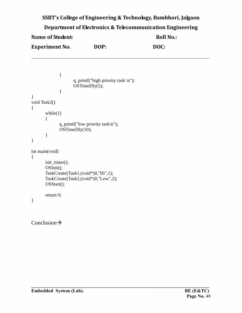
SSBT’s College of Engineering & Technology, Bambhori, Jalgaon
Department of Electronics & Telecommunication Engineering
Name of Student: Roll No.:
Experiment No. DOP: DOC:
___________________________________________________________________________
___________________________________________________________________________
Embedded System (Lab). BE (E&TC)
Page No. 48
{
q_printf("high priority task \n");
OSTimeDly(5);
}
}
void Task2()
{
while(1)
{
q_printf("low priority task\n");
OSTimeDly(10);
}
}
int main(void)
{
init_timer();
OSInit();
TaskCreate(Task1,(void*)0,"Hi",1);
TaskCreate(Task2,(void*)0,"Low",2);
OSStart();
return 0;
}
Conclusion