BCH101 ENGINEERING CHEMISTRY- I · BCH101 ENGINEERING CHEMISTRY- I UNIT – I WATER TECHNOLOGY...
86
BCH101 ENGINEERING CHEMISTRY- I UNIT – I WATER TECHNOLOGY INTRODUCTION Water is the nature’s most wonderful, abundant and useful compound. Of the many essential elements for the existence of human beings, animals and plants, water is rated to be of greatest importance. Without food human being can survive for a number of days, but water is such an essential thing without it one cannot survive. Water is not only essential for the lives of animals and plants but also occupies unique position in industries. Probably its most important use as an engineering material is in the ‘steam generation’. Water is also used as a coolant, in power, and chemical plants. In addition to it, water can also be used in the production of steel, rayon, paper, textiles, chemicals, irrigation, drinking fire fighting, etc. OCCURRENCE: Water is the only substance that occurs at ordinary temperatures in all three states of matter: Solid, Liquid and Gas. As a so33.3.33lid, ice, it forms glaciers, frozen lakes and rivers, snow, hail and frost. It is liquid as rain and dew, and it covers three- quarters of the earth’s surface in swamps, lakes, rivers and oceans. Water also occurs in the soil and beneath the earth’s surface asa vast groundwater reservoir. As gas, or water vapour, it occurs as fog, steam and clouds. WATER PURIFICATION: Impurities are removed from water by seeming, sedimentation, filtration, chlorination or irradiation. Aeration removes odours and tastes caused by decomposing organic matter, industrial wastes and some gases. Various salts and metals cause hardness in water. Hardness may be removed by boiling, by adding sodium carbonate and lime or by filtering through natural or artificial zeolites. Water is also purified by processes such as desalination, reverse osmosis, electrolysis etc.,
Transcript of BCH101 ENGINEERING CHEMISTRY- I · BCH101 ENGINEERING CHEMISTRY- I UNIT – I WATER TECHNOLOGY...
BCH101 ENGINEERING CHEMISTRY- I
UNIT – I WATER TECHNOLOGY
INTRODUCTION
Water is the nature’s most wonderful, abundant and useful compound. Of the many
essential elements for the existence of human beings, animals and plants, water is rated to be of
greatest importance. Without food human being can survive for a number of days, but water is
such an essential thing without it one cannot survive. Water is not only essential for the lives of
animals and plants but also occupies unique position in industries. Probably its most important
use as an engineering material is in the ‘steam generation’. Water is also used as a coolant, in
power, and chemical plants. In addition to it, water can also be used in the production of steel,
rayon, paper, textiles, chemicals, irrigation, drinking fire fighting, etc.
OCCURRENCE:
Water is the only substance that occurs at ordinary temperatures in all three states of
matter: Solid, Liquid and Gas. As a so33.3.33lid, ice, it forms glaciers, frozen lakes and rivers,
snow, hail and frost. It is liquid as rain and dew, and it covers three- quarters of the earth’s
surface in swamps, lakes, rivers and oceans. Water also occurs in the soil and beneath the earth’s
surface asa vast groundwater reservoir. As gas, or water vapour, it occurs as fog, steam and
clouds.
WATER PURIFICATION:
Impurities are removed from water by seeming, sedimentation, filtration, chlorination or
irradiation. Aeration removes odours and tastes caused by decomposing organic matter,
industrial wastes and some gases. Various salts and metals cause hardness in water. Hardness
may be removed by boiling, by adding sodium carbonate and lime or by filtering through natural
or artificial zeolites. Water is also purified by processes such as desalination, reverse osmosis,
electrolysis etc.,

CHARACTERISTICS OF WATER As per the suggestion given by World Health Organisation (WHO) and by Indian Council of
Medical Research (ICMR), the following are the important characteristics of potable water.
1. It should be clear, colourless and odourless.
2. It should be cool and pleasant to taste.
3. It should be free from harmful bacteria and suspended impurities.
4. It should be free from dissolved gases like CO2, H2S, NH3, etc., and poisonous minerals like
lead, arsenic, manganese, etc.,
5. Hardness should be less than 500 ppm.
6. Chloride ion content should be less than 250 ppm.
7. Fluoride ion content should be less than 1.5 ppm.
8. Total Dissolved Solids (TDS) content should be less than 500 ppm.
9. pH of the potable water should be 6.5 – 8.5.
CHEMICAL CHARACTERISTICS OF WATER
The most important chemical characteristics of water are its acidity, alkalinity, hardness
and corrosiveness. Chemical impurities can be either natural, man made (Industrial) or be
deployed in raw water sources by enemy forces.
Some chemical impurities cause water to behave as either an acid or a base. Since either
condition has an important bearing on the water treatment process, the pH value must be
determined. Generally the pH influences the corrosiveness of the water, chemical dosages
necessary for proper disinfection and the ability to detect contaminants.
Acidic Neutral Alkaline
pH=0-7 7 pH=7-14
HARDNESS
Hardness is caused by the soluble salts of calcium, magnesium, iron, manganese, sodium,
sulphates, chlorides and nitrates. The degree of hardness depends on the type and amount of
impurities present in the water. Hardness also depends on the amount of carbon-di-oxide in
solution. Carbon-di-oxide influences the solubility of the impurities that cause hardness.
The hardness caused by carbonates and bicarbonates is called carbonate hardness. The hardness
caused by all others (chlorides, sulphates, nitrates) is called non-carbonated hardness.
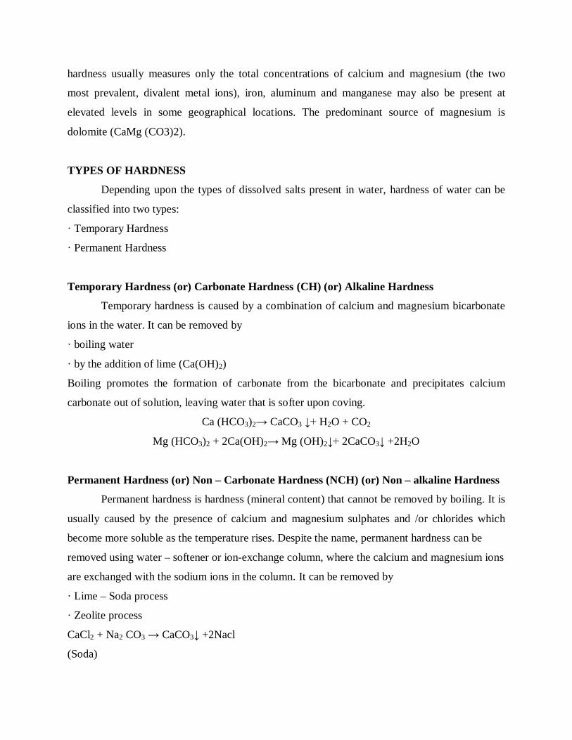
HARD WATER
Water which does not produce lather with soap solution, but produces whiteprecipitate
(scum) is called hard water.In other words, water that contains mineral salts (an calcium and
magnesium ions)that limit the formation of lather with soap.
This is due to the presence of dissolved Ca and Mg salts.
SOFT WATER
Water, which produces lather, readily with soap solution is called soft water. This is due
to the absence of Ca and Mg salts.Water that is not hard (ie., does not contain mineral salts that
interfere with the formation of lather with soap).
HARDNESS OF WATER
How to detect hardness?
Hardness of water can be detected in two ways.
· When the water is treated with soap solution, if it prevents lathering and forms white scum, the
water contains hardness.
· Water containing hardness, gives wine red colour with Eriochrome Black –T indicator.
The total water hardness (including both Ca2+ and Mg2+ ions) is read as parts per million (ppm)
or weight / volume (mg/L) of Calcium Carbonate (CaCO3) in the water. Although water
hardness usually measures only the total concentrations of calcium and magnesium (the two
most prevalent, divalent metal ions), iron, aluminum and manganese may also be present at
elevated levels in some geographical locations. The predominant source of magnesium is
dolomite (CaMg (CO3)2).
TYPES OF HARDNESS
Depending upon the types of dissolved salts present in water, hardness of water can be
classified into two types:
· Temporary Hardness
· Permanent Hardness
Temporary Hardness (or) Carbonate Hardness (CH) (or) Alkaline Hardness
Temporary hardness is caused by a combination of calcium and magnesium bicarbonate
ions in the water. It can be removed by
· boiling water
· by the addition of lime (Ca(OH)2)
Boiling promotes the formation of carbonate from the bicarbonate and precipitates calcium
carbonate out of solution, leaving water that is softer upon coving.
Ca (HCO3)2→ CaCO3 ↓+ H2O + CO2
Mg (HCO3)2 + 2Ca(OH)2→ Mg (OH)2↓+ 2CaCO3↓ +2H2O
Permanent Hardness (or) Non – Carbonate Hardness (NCH) (or) Non – alkaline Hardness
Permanent hardness is hardness (mineral content) that cannot be removed by boiling. It is
usually caused by the presence of calcium and magnesium sulphates and /or chlorides which
become more soluble as the temperature rises. Despite the name, permanent hardness can be
removed using water – softener or ion-exchange column, where the calcium and magnesium ions
are exchanged with the sodium ions in the column. It can be removed by
· Lime – Soda process
· Zeolite process
CaCl2 + Na2 CO3 → CaCO3↓ +2Nacl
(Soda)

CaSO4 + Na2Ze →CaZe + Na2SO4
Zeolite =(Na2 Al2 Si2 O8. X H2O)
Hard water causes scaling, which is the left- over mineral deposits that are formed after the hard
water had evaporated. This is also known as lime scale.
Total Hardness
The sum of temporary hardness and permanent hardness.
Table 1 :1 Molecular weights of some hardness producing salts.
Expression of hardness in terms of equivalents of CaCO3
The concentration of hardness producing salts are usually expressed in terms of an
equivalent amount of CaCO3. CaCO3 is chosen as a standard because,
i) Its molecular weight (100) and equivalent weight (50) is a whole number, so the
Calculations in water analysis can be simplified.
Hardness
producing salt
Molecular
weight Hardness producing salt
Molecular
weight
Ca(HCO3)2 162 MgSO4 120
Mg(HCO3)2 146 MgCO3 84
Mg(NO3)2 148 MgCl2 95
Ca(NO3)2 164 CaCl2 111
CaCO3 100 Ca2+ 40
CaSO4 136 Mg2+ 24

ii) It is the most insoluble salt, that can be precipitated in water treatment. If the concentration of
hardness producing salt is x mgs/lit. then
Example
If the concentration ( or) weight of CaSO4 is 43mgs/lit, then weight equivalent to
UNITS OF HARDNESS
1. Parts per million (ppm)
It is defined as the number of parts of CaCO3 equivalent hardness per 106 parts of water.
2. Milligrams per litre (mg/lit)
It is defined as the number of milligrams of CaCO3 equivalent hardness per 1 litre of water.
3. Clarke’s degree (oCl)
It is defined as the number of parts of CaCO3 equivalent hardness per 70,000 parts of water.
4. French degree (oFr)
It is defined as the number of parts of CaCO3 equivalent hardness per 105 parts of water.
Relationship between various units
1ppm = 1 mg/lit = 0.10 Fr = 0.070 Cl
ESTIMATION OF TOTAL HARDNESS OF WATER BY EDTA METHOD
The hardness of water is estimated by EDTA method using Eriochrome Black –T [EBT].
Principle:
The calcium ion in the water is capable of forming complex with Indicator EBT and also
with the EDTA in the pH range 8- 10.To keep the solution at this pH range , a buffer [ mixture of
ammonium chloride and ammonium hydroxide ] is used . The complex between EDTA and
indicator is more stable that of between the metal ion and indicator

Experiment :
1.Preparation of Standard hard water :
Hard water is prepared in such a way that 100 ml of containing 100 mg of Calcium
carbonate;
So , 1 ml of Std. hard water = 1mg
2.Standadisation of EDTA :
EDTA is taken in the burette; 20 ml of Std. hard water is pipette out in beaker; 5ml of
buffer solution and 2 a few drops of indicator are added ; now the solution becomes wine –red
colour because the colour of the complex between calcium and indicator [ M- In ] is wine –red.
Then it is titrated against EDTA; at the end point the colour changes to Pale blue, which is colour
of the free indicator. Since the complex between metal ion -EDTA is more stable that of between
the metal ion and indicator , the Metal moves from [M-In] towards EDTA and forms complex
with that , which is colourless; now the indicator is freed and the solutions attains steel blue
colour , which is the colour of the free indicator. Let the titre value be V1.
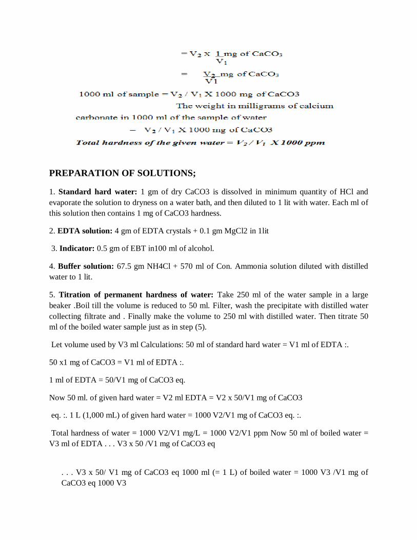
PREPARATION OF SOLUTIONS;
1. Standard hard water: 1 gm of dry CaCO3 is dissolved in minimum quantity of HCl and evaporate the solution to dryness on a water bath, and then diluted to 1 lit with water. Each ml of this solution then contains 1 mg of CaCO3 hardness.
2. EDTA solution: 4 gm of EDTA crystals + 0.1 gm MgCl2 in 1lit
3. Indicator: 0.5 gm of EBT in100 ml of alcohol.
4. Buffer solution: 67.5 gm NH4Cl + 570 ml of Con. Ammonia solution diluted with distilled water to 1 lit.
5. Titration of permanent hardness of water: Take 250 ml of the water sample in a large beaker .Boil till the volume is reduced to 50 ml. Filter, wash the precipitate with distilled water collecting filtrate and . Finally make the volume to 250 ml with distilled water. Then titrate 50 ml of the boiled water sample just as in step (5).
Let volume used by V3 ml Calculations: 50 ml of standard hard water = V1 ml of EDTA :.
50 x1 mg of CaCO3 = V1 ml of EDTA :.
1 ml of EDTA = 50/V1 mg of CaCO3 eq.
Now 50 ml. of given hard water = V2 ml EDTA = V2 x 50/V1 mg of CaCO3
eq. :. 1 L (1,000 mL) of given hard water = 1000 V2/V1 mg of CaCO3 eq. :.
Total hardness of water = 1000 V2/V1 mg/L = 1000 V2/V1 ppm Now 50 ml of boiled water = V3 ml of EDTA . . . V3 x 50 /V1 mg of CaCO3 eq
. . . V3 x 50/ V1 mg of CaCO3 eq 1000 ml (= 1 L) of boiled water = 1000 V3 /V1 mg of CaCO3 eq 1000 V3

Permenent hardness = /V1 ppm = . . .
And Temporary hardness = Total hardness – Permanent hardness= ppm =
3.1 Advantages of EDTA method:
This method is definitely preferable to the other methods, because of the
(i) Larger accuracy; (ii) Convenience; (iii) Rapid procedure
ALKALINITY
Alkalinity is classified as
Depending up on the anions that are responsible for the alkalinity of water, there are three
types of alkalinity: 1. Hydroxide alkalinity – due to hydroxide ions
2. Carbonate alkalinity - due to carbonate ions
3. Bicarbonate alkalinity - due to bicarbonate ions
The alkalinity due hydroxide and carbonate can be detected by Phenolphthalein
indicator and so they are collectively called as Phenolphthalein Alkalinity , represented
by P.
The alkalinity due hydroxide, carbonate and bicarbonate can be detected by Methyl
orange indicator and so it is called as in Methyl orange Alkalinity, represented by M.
1.Determination of Phenolphthalein Alkalinity ,P :
100 ml of given water sample is taken in the conical flask , a few drops of
Phenolphthalein indicated are added and titrated against N/50 H2SO4 ; let the titre value
when the solution becomes colourless, be V1.
2.Determination of Methylorange Alkalinity ,M :
The in the same solution a few drops of Methylorange indicator are added and
titrated against the same acid until the colour changes from yellow to red ; let the titre
value be X .
So, M = V1 + X = V2

(a)Calculation of P:
Volume of the acid = V1 cc
Normality of the acid , N1 = 1/50
Volume of water , V2 = 100 cc
Normality of water N2 = V1 X 1/50 X 1/ 100
P in terms of CaCO3 = N2 x equivalent of CaCO3 X 1000 mg
of CaCO3
= V1 X 1/50 X 1/ 100 X 50 X 1000 mg of CaCO3
= 10 V1
P = 10 V1 ppm
(a)Calculation of M:
Volume of the acid = V2 cc
Normality of the acid, N2 = 1/50
Volume of water, V1 = 100 cc
Normality of water N1 = V2 X 1/50 X 1/ 100
M in terms of CaCO3 = N1 x equivalent of CaCO3 X 1000 mg of CaCO3
= V2 X 1/50 X 1/ 100 X 50 X 1000 mg of CaCO3
= 10 V2
M = 10 V2 ppm
ALKALINITY HYDROXIDE CARBONATE BICARBONATE
P= 0 0 0 M
P = 1/2 M 0 2P 0
P = M M or P 0 0
P < 1/2 M 0 2P M - 2P
P > 1/2 M 2P - M 2(M - P ) 0

1.When OH - only present ; [ H CO3 - = 0 & CO3
2- = 0 ]
P = M
OH P M
1/2CO3
H CO3
H CO3 2. when CO3
2- only present ; [ H CO3 - = 0 & OH - = 0 ] ;
2P = M or P = M/2
OH
1/2CO3 P M
HCO3 - P
HCO3 -
3. when HCO3 - only present [ CO3
2- = 0 & OH- = 0 ]
HCO3 - =M ; P = 0
OH
1/2CO3
HCO3 -
HCO3 - M
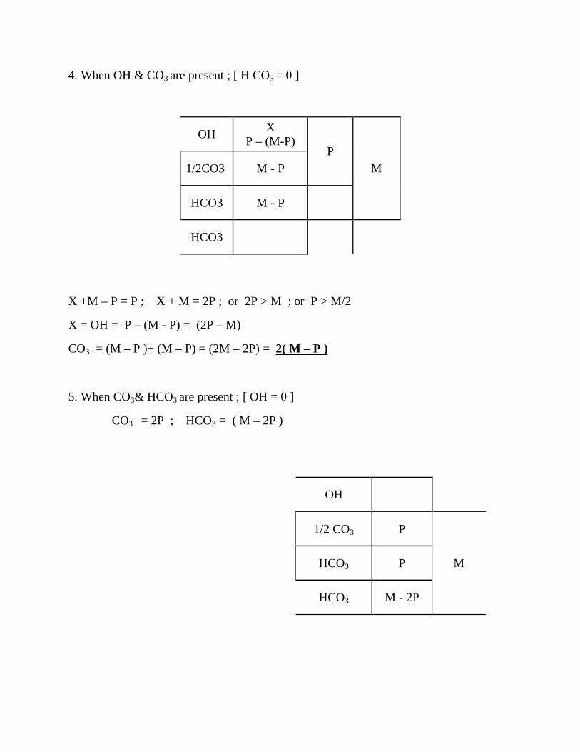
4. When OH & CO3 are present ; [ H CO3 = 0 ]
OH X P – (M-P)
P M 1/2CO3 M - P
HCO3 M - P
HCO3
X +M – P = P ; X + M = 2P ; or 2P > M ; or P > M/2
X = OH = P – (M - P) = (2P – M)
CO3 = (M – P )+ (M – P) = (2M – 2P) = 2( M – P )
5. When CO3& HCO3 are present ; [ OH = 0 ]
CO3 = 2P ; HCO3 = ( M – 2P )
OH
1/2 CO3 P
M HCO3 P
HCO3 M - 2P
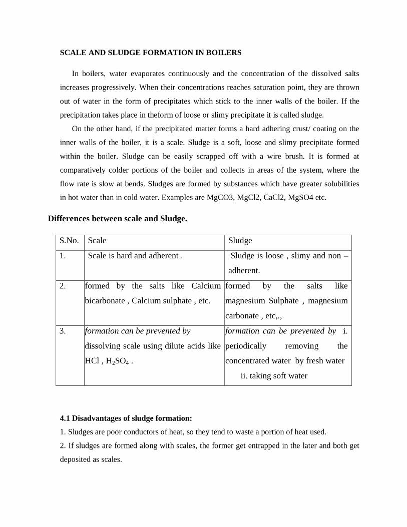
SCALE AND SLUDGE FORMATION IN BOILERS
In boilers, water evaporates continuously and the concentration of the dissolved salts
increases progressively. When their concentrations reaches saturation point, they are thrown
out of water in the form of precipitates which stick to the inner walls of the boiler. If the
precipitation takes place in theform of loose or slimy precipitate it is called sludge.
On the other hand, if the precipitated matter forms a hard adhering crust/ coating on the
inner walls of the boiler, it is a scale. Sludge is a soft, loose and slimy precipitate formed
within the boiler. Sludge can be easily scrapped off with a wire brush. It is formed at
comparatively colder portions of the boiler and collects in areas of the system, where the
flow rate is slow at bends. Sludges are formed by substances which have greater solubilities
in hot water than in cold water. Examples are MgCO3, MgCl2, CaCl2, MgSO4 etc.
Differences between scale and Sludge.
S.No. Scale Sludge
1. Scale is hard and adherent . Sludge is loose , slimy and non –
adherent.
2. formed by the salts like Calcium
bicarbonate , Calcium sulphate , etc.
formed by the salts like
magnesium Sulphate , magnesium
carbonate , etc,.,
3. formation can be prevented by
dissolving scale using dilute acids like
HCl , H2SO4 .
formation can be prevented by i.
periodically removing the
concentrated water by fresh water
ii. taking soft water
4.1 Disadvantages of sludge formation:
1. Sludges are poor conductors of heat, so they tend to waste a portion of heat used.
2. If sludges are formed along with scales, the former get entrapped in the later and both get
deposited as scales.

3. Excessive sludge formation disturbs the working of the boiler. It settles in the regions of
poor water circulation such as pipe connection, plug opening, gauge glass connection thereby
causing even chocking of the pipes.
4.2 Prevention of sludge formation:
1. By using well softened water. 2. By a frequent blow down operation, i.e., drawing off a
portion of the concentrated water Scales are hard deposits, which stick very firmly to the
inner surface of the boiler. Scales are very difficult to remove even with the help of hammer
and chisel. Scales are the main source of boiler troubles. Formation of scales may be due to
1. Decomposition of calcium bicarbonate
Ca(HCO3)2 → CaCO3 + H2O + CO2
However, scale composed chiefly of calcium carbonate is soft and is the main cause of scale
formation in low pressure boilers. But in high pressure boilers CaCO3 is soluble.
CaCO3 + H2O→Ca(OH)2 + CO2
2. Decomposition of calcium sulphate:
The solubility of calcium sulphate in water decreases with increase in temperature. Thus,
solubility of calcium sulphate is 3,200 ppm at 15 oC and it reduces to 55 ppm at 230 oC and
27 ppm at 320 oC. In other words, calcium sulphate is soluble in cold water, but almost
completely insoluble in superheated water. Consequently calcium sulphate gets precipitated
as hard scale on the heated portions of the boiler. This is the main cause in the high pressure
boilers.
3. Hydrolysis of magnesium salts:
Dissolved magnesium salts undergo hydrolysis at prevailing high temperatures in the boiler
forming magnesium hydroxide precipitate, which forms a soft type of scale.
MgCl2 + 2H2O →Mg(OH)2 + 2HCl
4. Presence of silica: (SiO2), even if present in small quantities, deposits as calcium silicate
(CaSiO3) and/ or magnesium silicate (MgSiO3). These deposits stick very firmly to the inner
walls of the boiler surface and are very difficult for removal. One important source of silica
in water is the sand filter used.
4.3 Disadvantages of scale formation:
1. Wastage of fuels: Scales have a low thermal conductivity, so the rate of transfer of heat
from boiler to inside water is largely decreased. In order to provide a steady supply of heat to
water, excessive or over heating is done which causes unnecessary increase in fuel
consumption. Thickness of the scale (mm) 0.325 0.625 1.25 2.5 12 Wastage of fuel 10% 15%
50% 80% 150%
2. Lowering of boiler safety:
Due to scale formation, over-heating of the boiler has to be done in order to maintain a
constant supply of steam. The over-heating of the boiler tube makes the boiler material softer
and weaker and this causes distortion of the boiler tube and makes the boiler tube unsafe to
bear the pressure of the steam especially in high-pressure boilers.
3. Decrease in efficiency:
Scales may sometimes get deposited in the valves and condensers of the boiler and choke
them partially or totally. This results in decrease the efficiency of the boiler.
4. Danger of explosion:
When thick scales crack due to uneven expansion, the water comes in contact with the
overheated iron plates. This causes a release of a large amount of steam suddenly, developing
a high pressure, which may cause explosion in the boiler.
4.4 Removal of scales:
1. With the help of scraper or piece of wood or wire brush, if they are loosely adhering.
2. By giving thermal shocks like heating the boiler and suddenly cooling it with cold water.
3. Dissolving scales by adding suitable chemicals, if they are adherent and hard. Thus
calcium carbonate scales can be dissolved by the addition of 5% HCl. Calcium sulphate
scales can be dissolved by the addition of EDTA ( ethylene diamine tetra acetic acid), with
which they form complexes.
4. By frequent blow down operation, if the scales are loosely adhering.
5. CAUSTIC EMBRITTELMENT
Caustic embrittlement is a type of boiler corrosion, caused by using highly alkaline water
in the boiler. During softening process by lime- soda process, free sodium carbonate is
usually present in small proportion in the softened water. In high pressure boilers, sodium
carbonate decomposes to give sodium hydroxide and carbon dioxide, and their presence
makes the boiler water caustic.

Na2CO3 + H2O → NaOH + CO2
The water containing sodium hydroxide flows into the minute hair cracks always present, by
capillary action in to the inner sides of the boiler. Here as water evaporates the dissolved
caustic soda concentration increases progressively. This concentrated caustic soda attacks the
surrounding area dissolving inner iron side of the boiler by forming sodium ferroate. This
causes the embrittlement of the boiler parts, particularly stressed parts such as bends, joints,
rivets etc., causing even failure of the boiler operations. Caustic cracking can be explained by
the following concentration cell Iron at Bends, rivets and joints
The iron surrounded by the dilute NaOH becomes the cathodic surface and the iron present
with the high concentration of NaOH becomes anodic which is consequently dissolved or
corroded.
5.1 Caustic embrittlement can be avoided by
1. By using sodium phosphate as a softening agent instead of sodium carbonate.
2. By adding tannin or lignin to the boiler water, since these substances block the hair cracks,
thereby preventing the infiltration of the caustic soda solution in to these.
3. By adding sodium sulphate to boiler water: Sodium sulphate blocks the hair cracks
preventing the infiltration of caustic soda solution in to these. It has been observed that
caustic cracking can be prevented, if sodium sulphate is added to the boiler in the ratio of
Na2SO4 : NaOH as 1:1; 2:1; 3:1 in boilers working respectively at pressures up to 10, 20 and
above 20 atmospheres.
6. BOILER CORROSION
Boiler corrosion is the decay of boiler material (iron) either by chemical or electro chemical
attack of its environment. Main reasons for the boiler corrosion are:
6.1 Dissolved oxygen:
Water usually contains 8 mg of dissolved oxygen per liter at room temperature. Dissolved
oxygen in water in the presence of prevailing high temperature of the boiler, attacks the boiler
material as

2Fe + 2 H2O + O2→ 2 Fe(OH)2
4 Fe(OH)2 + O2→2 [Fe2O3.2 H2O]
Removal of the dissolved oxygen:
a. By adding calculated amount of sodium sulphite or hydrazine or sodium sulphide.
2Na2SO3 + O2 →2 Na2SO4
N2H4 + O2 → N2 + 2 H2O
Na2S + O2 → Na2SO4
b. Mechanical de-aeration:
In this process water is sprayed in to a tower fitted with perforated plates (Fig), heated from
sides and connected to vacuum pump. High temperature, low pressure and large exposed surface
area reduce the dissolved oxygen in water.
6.2 Dissolved carbon dioxide:
Carbon dioxide dissolved in water forming carbonic acid, has a slow corrosive effect on the
boiler material. Carbon dioxide is also released inside the boiler, if water, containing
bicarbonates is used for steam generation
CO2 + H2O → H2CO3
Mg(HCO3)2 → MgCO3 + CO2 + H2O
Removal of dissolved carbon dioxide: a. By adding calculated amount of ammonia
2NH4OH + CO2 → (NH4)2CO3
b. By mechanical de-aeration process along with oxygen (described above)
6.3 Acids from dissolved salts:
Water containing dissolved salts of magnesium liberates acids on hydrolysis.
MgCl2 + H2O → Mg(OH)2 + 2 HCl
The liberated acid reacts with the iron material of the boiler in chain like processes, producing
HCl again and again.
Fe + 2HCl→FeCl2+ H2
FeCl2 + 2H2O → Fe(OH)2 + 2 HCl
Consequently, presence of even small amount of magnesium chloride will cause corrosion to a
large extent and may cause damage to the boiler material. Removal of acids: a) Softening boiler
water to remove magnesium chloride, if any. b) By frequent blow down operation of removal of
concentrated water with fresh soft water. c) Addition of inhibitors as sodium silicate/sodium
phosphate/sodium chromate, which protect the boiler material against acid attack.
7. PRIMING AND FOAMING
When a boiler is producing steam rapidly, some particles of the condensed liquid water are
carried along with the steam. The process of wet steam formation is called priming. Priming is
causedby
1. The presence of large amounts of dissolved solids
2. High steam velocities
3. Sudden boiling
4. Improper boiler design
5. Sudden increase in the steam production rate.
Foaming is the production of persistent foam or bubbles in boilers, which do not break easily.

Foaming is due to the presence of substances like oils in water, which reduce the surface tension
of water.Priming and foaming usually occur together. They have to be eliminated because
a. Dissolved salts in boiler water are carried by the wet steam to super heater and turbine blade,
where they get deposited as water evaporates. This deposit reduces the efficiency of the boiler.
b. Dissolved salts may enter the other parts of the machinery, where steam is being used, thereby
decreasing the life of the machinery
c. Actual height of the water column cannot be judged properly making the maintenance of the
boiler pressure difficult.
Priming can be avoided by fitting mechanical steam purifiers, avoiding the rapid change in
steaming rate, maintaining low water levels in boilers, efficient softening and filtration of the
boiler feed water. Foaming can be avoided by adding anti foaming chemicals like castor oil, or
removing oil from boiler water by adding compounds like sodium aluminate.
8. SOFTENING METHODS
Water used for industrial purposes (such as for steam generation) should be sufficiently pure. it
should, therefore, be freed from hardness- producing salts before it is being put to use. The
process of removing hardness-producing salts from water is known as softening of water. In
industry three methods are mainly employed for softening of water.
8.1 Lime soda process:
In this method, the soluble calcium and magnesium salts in water are chemically converted into
insoluble compounds, by adding calculated amounts of lime [Ca(OH)2] and soda [Na2CO3].
Calcium carbonate [CaCO3] and magnesium hydroxide [Mg(OH)2] are precipitated and
removed.
8.2 Ion exchange or de-ionization or de-mineralization process:
Ion-exchange resins are insoluble, cross-linked, long chain organic polymers with a microporous
structure, and the “functional groups’ attached to the chains are responsible for the ion-
exchanging properties. Resins containing acidic functional groups (-COOH, -SO3H etc.) are
capable of exchanging their H+ ions with other cations, which come into their contact; whereas
those containing basic functional groups (-NH2=NH as hydrochloric acid) are capable of
exchanging their anions with other anions, which come into their contact.
The ion-exchange resins may be classified as: (i) Cation exchange resins (RH+ ) are mainly
styrene-divinyl benzene copolymers, which on sulphonation or carboxylation become capable to
exchange their hydrogen ions with the cations present in the raw water
(ii) Anion exchange resins (R1OH- ) are styrene-divinyl benzene amineformaldehyde
copolymers, which contains amino or quaternary ammonium or quaternary phosphonium or
tertiary sulphonium groups as an integral part of the resin matrixs. These, after treatment with
dil. NaOH solution, become capable to exchange their OHanions with anions present in the raw
water.
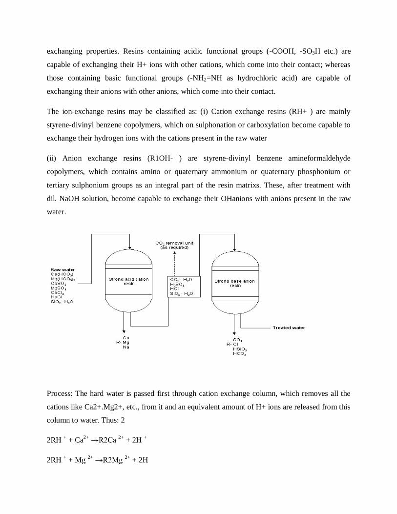
Process: The hard water is passed first through cation exchange column, which removes all the
cations like Ca2+.Mg2+, etc., from it and an equivalent amount of H+ ions are released from this
column to water. Thus: 2
2RH + + Ca2+ →R2Ca 2+ + 2H +
2RH + + Mg 2+ →R2Mg 2+ + 2H

The water which is now free from cations, is passed through anion exchange column, which
removes all the anions like SO4 2- , Cletc., present in the water and equivalent amount OHions
are released from this column to water. Thus:
R'OH - + Cl-→R'Cl + OH –
2R'OH - + SO42-→R'2 SO4
2- + 2OH –
2R'OH - + CO32-→R'2 CO3
2- + 2OH -
H + and OHions (released from cation exchange and anion exchange columns respectively)
combine to produce water.
H + + OH - → H2O
Thus the water coming out from the exchanger is free from all cations as well as anions. Ion-free
water is known as deionised or demineralised water.
Regeneration: When capacities of cation and anion exchangers to exchange H+ and OHions
respectively are lost, they are then said to be exhausted
The exhausted cation exchange column is regenerated by passing a solution of dil. HCl or
H2SO4. The regeneration can be represented as:
R2Ca 2+ + 2H + → 2RH + + Ca2+ (Washing)
The column is washed with deionized water and such washing (which containing Ca2+, Mg2+,
etc. and cation SO42- ) is passed into sink or drain. The exhausted anion exchange column is
regenerated by passing a solution of dil. NaOH. The regeneration can be represented as:
R' 2 SO4 2- + 2OH - → 2R'OH - + SO42- (Washing)
The column is washed with deionized water and such washing (which contains Na+ and SO42- or
Clions) is passed into sink or drain.
Advantages
(1) The process can be used to soften highly acidic or alkaline waters. (2) It produces water of
very low hardness (2 ppm) .
Disadvantages
(1) The equipment is costly and expensive chemicals are needed.
(2) If water contains turbidity, then the output of the process is reduced.
(3) The turbidity must be below 10 ppm. If it is more, it has to be removed first by coagulation
followed by filtration.
9. Potable water
The water which is fit for human consumption is known as potable water
Municipalities have to supply potable water, i.e., water which is safe to human consumption
should satisfy the following essential requirements
1. It should be sparkling clear and odourless.
2. It should be pleasant in taste
3. It should be perfectly cool
4. Its turbidity should not exceed 10 ppm
5. It should be free from objectionable dissolved gases like hydrogen sulphide.
6. It should be free from objectionable minerals such as lead, arsenic, chromium and manganese
salts.
7. Its alkalinity should not be high. Its pH should not be above 8.0
8. It should be reasonably soft
9. Its total dissolved solids should be less than 500 ppm
10. It should be free from disease- producing micro- organisms.
Purification of domestic water for domestic use:
For removing various types of impurities in the natural water from various sources, the following
treatment process is employed;
9.1 Removal of suspended impurities :
The treatment water for municipal supply involves the following steps:
1.Screening :
It is a process of removing the floating materials like , leaves , wood pieces ,etc.,
from water. Here water is passed through a screen having a number of holes .
2.Aeration :
The process of mixing air with water is called aeration; here the gases like CO2,
H2S and other volatile impurities responsible for the bad taste and odour, are removed; further
ferrous and manganeous salts are converted into insoluble ferric and manganic salts .
3.Sedimentation :
In this process suspended impurities are removed by keeping the water undisturbed for 2
– 6 hours in a tank. This removes only 75 % of the suspended impurities.
4.Coagulation :
In this method by adding coagulants like aluminium sulphate, the colloidal impurities like
finely divided clay, silica, etc., are also removed. The aluminium sulphatehydrolysed to give
gelatinous precipitate Al(OH)3 ; The suspended impurities adhere to the precipitate and settle
down at the bottom.
Al2(SO4)3 + H2O Al(OH)3 + H2 SO4
5.Filtration :
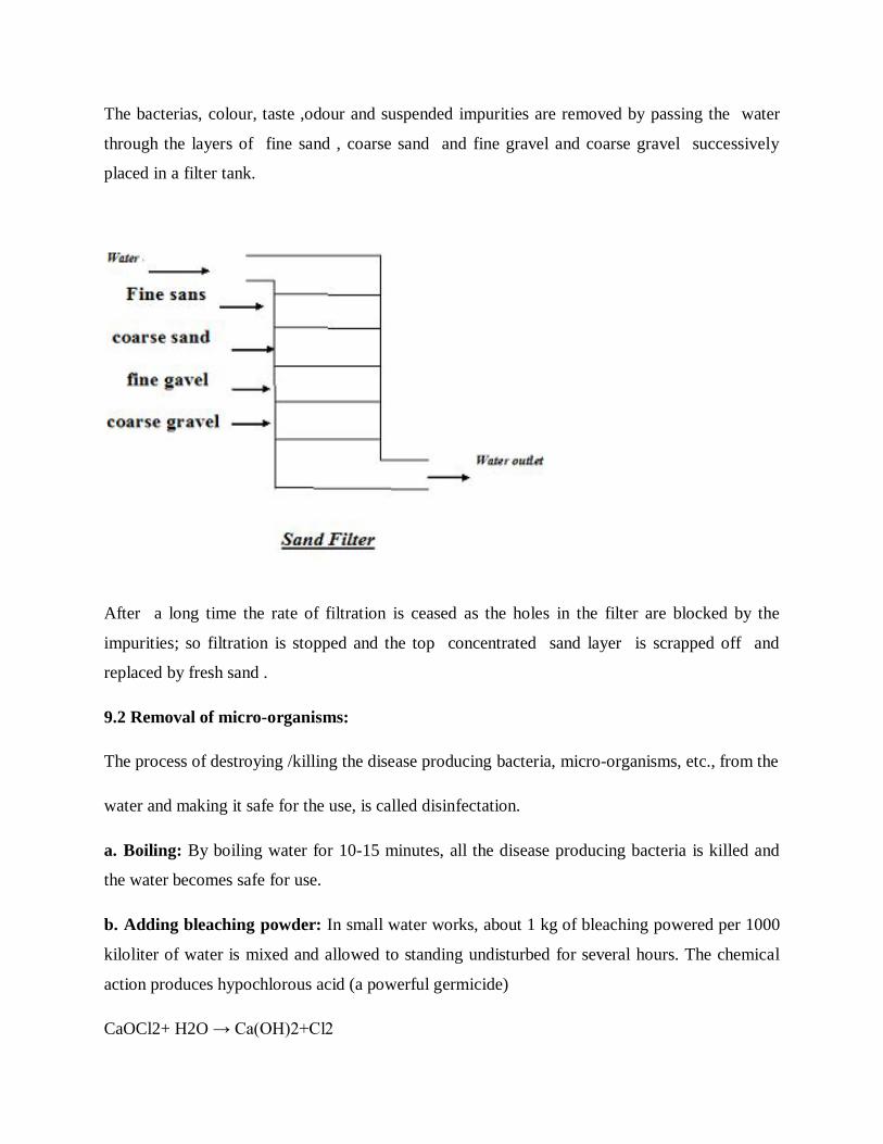
The bacterias, colour, taste ,odour and suspended impurities are removed by passing the water
through the layers of fine sand , coarse sand and fine gravel and coarse gravel successively
placed in a filter tank.
After a long time the rate of filtration is ceased as the holes in the filter are blocked by the
impurities; so filtration is stopped and the top concentrated sand layer is scrapped off and
replaced by fresh sand .
9.2 Removal of micro-organisms:
The process of destroying /killing the disease producing bacteria, micro-organisms, etc., from the
water and making it safe for the use, is called disinfectation.
a. Boiling: By boiling water for 10-15 minutes, all the disease producing bacteria is killed and
the water becomes safe for use.
b. Adding bleaching powder: In small water works, about 1 kg of bleaching powered per 1000
kiloliter of water is mixed and allowed to standing undisturbed for several hours. The chemical
action produces hypochlorous acid (a powerful germicide)
CaOCl2+ H2O → Ca(OH)2+Cl2
Cl2+ H2O → HCl+ HOCl
Germs+ HOCl → Germs are killed
c. Chlorination: Chlorination (either gas or in concentrated solution from) produces
hypochlorous acid, which is a powerful germicide.
Cl2+ H2O → HCl+ HOCl
Bacteria+ HOCl → Bacteria are destroyed
9.3. Break point chlorination (or) or free residual chlorination :
It involves addition of sufficient amount of chlorine to oxidize: (a) organic matter (b)reducing
substance and (c) free ammonia in raw water; leaving behind mainly free chlorine, which
possesses disinfecting action against disease- producing bacteria The addition of chlorine at the
dip or break is called “break point” chlorination. This indicates the point at which free residual
chlorine begins to appear..
Advantages:
(1) It oxides completely organic compounds, ammonia and other reducing compounds.
(2) It removes color, odour and taste of water. (3) It removes completely all the disease causing
bacteria/micro-organism (4) It prevents the growth of any weeds in water.
9.4. Using Chloramine (ClNH2):
When chlorine and ammonia are mixed in the ratio of 2:1 by
volume, chloramine is formed. Cl2+NH3 → ClNH2+ HCl
Chloramine is a better bactericidal than chlorine.
9.5. Disinfection by Ozone:
Ozone gas is an excellent disinfectant, which is produced by passing
silent electric discharge through cold and dry oxygen.

3O2 → 2O3
O3 → O2 + [O]
10. Desalination of brackish water
The process of removing common salt (NaCl) from the water is known as desalination. Water
containing high concentration of dissolved salts with a peculiar salty taste is called brackish
water. Sea water is an example containing 3.5% of dissolved salts. The common methods for the
desalination of brackish water are;
10.1 Eletctrodialysis:
It is a method in which the ions are pulled out of the salt water by passing direct current, using
electrodes and thin rigid plastic membrane pair.
An Eletctrodialysis cell consists of a large number of paired sets of rigid plastic membranes.
Hard water is passed between the membrane pairs and an electric field is applied perpendicular
to the direction of water flow. Positively charged membrane and negatively charged membrane
repel positively charged ions and negatively charged ions respectively to pass through. So, in one
compartment of the cell, the salt concentration decreases while in the adjacent compartment it
increases
Thus, we get alternative stream of pure water and concentrated brine. Advantages: 1. It is most
compact unit
10.2 Reverse osmosis:
When two solutions of unequal concentrations are separated by a semi permeable membrane,
flow of solvent takes place from dilute to concentrate sides, due to osmosis. If, however a
hydrostatic pressure in excess to osmotic pressure is applied on the concentrated side, the solvent
flow is reversed, i.e, solvent is forced to move from concentrated side to dilute side across the
membrane. This is the principle of reverse osmosis.(RO)
Thus in reverse osmosis method, pure solvent is separated from its contaminants, rather than
removing contaminants from the water. The membrane filtration is sometimes also called super-
filtration or hyper filtration.
METHOD:
In this process, pressure is applied to the sea water or impure water to force the pure water
content of it out the semi-permeable membrane, leaving behind the dissolve solids. The principle
of reverse osmosis as applied for treating saline/sea water The membrane consists of very thin
film of cellulose acetate, affixed to either side of a perforated tube. However, more recently
superior membranes made of polymethacrylate and polyamide polymers have come into use.
ADVANTAGES
1. Reverse osmosis possesses distinct advantages of removing ionic as well as non-ionic,
colloidal and high molecular weight organic matter.
2. It removes colloidal silica, which is not removed by demineralization.
3. The maintenance cost is almost entirely on the replacement of the semi permeable membrane.
4. The life time of membrane is quite high, about 2 years,
5. The membrane can be replaced within a few minutes, thereby providing nearly uninterrupted
water supply.
6. Due to low capital cost, simplicity, low operating cost and high reliability, the reverse
osmosis is gaining grounds at present for converting sea water into drinking water and for
obtaining water for very high –pressure boilers.
BCH101 ENGINEERING CHEMISTRY- I
UNIT – II
POLYMERS
A polymer (Greek poly-, "many" + -mer, "parts") is a large molecule, or macromolecule,
composed of many repeated subunits. Because of their broad range of properties, both synthetic
and natural polymers play an essential and ubiquitous role in everyday life. Polymers range from
familiar synthetic plastics such as polystyrene to natural biopolymers such
as DNA and proteins that are fundamental to biological structure and function. Polymers, both
natural and synthetic, are created via polymerization of many small molecules, known
as monomers. Their consequently large molecular mass relative to small
molecule compounds produces unique physical properties, including toughness, viscoelasticity,
and a tendency to form glasses and semi crystalline structures rather than crystals.
The term "polymer" derives from the ancient Greek word (polus, meaning "many,
much") and (meros, meaning "parts"), and refers to a molecule whose structure is composed of
multiple repeating units, from which originates a characteristic of high relative molecular
mass and attendant properties. The units composing polymers derive, actually or conceptually,
from molecules of low relative molecular mass. The term was coined in 1833 by Jöns Jacob
Berzelius, though with a definition distinct from the modern IUPAC definition. The modern
concept of polymers as covalently bonded macromolecular structures was proposed in 1920
by Hermann Staudinger, who spent the next decade finding experimental evidence for this
hypothesis.
Polymers are of two types:
Natural polymeric materials such as shellac, amber, wool, silk and natural rubber have been
used for centuries. A variety of other natural polymers exist, such as cellulose, which is the
main constituent of wood and paper.
The list of synthetic polymers includes synthetic rubber, phenol formaldehyde
resin (or Bakelite), neoprene, nylon, polyvinyl chloride (PVC or

vinyl), polystyrene, polyethylene, polypropylene, polyacrylonitrile, PVB, silicone, and many
more.
Most commonly, the continuously linked backbone of a polymer used for the preparation of
plastics consists mainly of carbon atoms. A simple example is polyethylene ('polythene' in
British English), whose repeating unit is based on ethylene monomer. However, other structures
do exist; for example, elements such as silicon form familiar materials such as silicones,
examples being Silly Putty and waterproof plumbing sealant. Oxygen is also commonly present
in polymer backbones, such as those of polyethylene glycol, polysaccharides (in glycosidic
bonds), and DNA (in phosphodiester bonds).
TYPES OF POLYMERS
1. Oligopolymers 2.Highpolymers
3. Homopolymers 4.Heteropolymers.
MONOMER ARRANGEMENT IN COPOLYMERS
Monomers within a copolymer may be organized along the backbone in a variety of ways.
Alternating copolymers possess regularly alternating monomer residues [AB...]n
Periodic copolymers have monomer residue types arranged in a repeating sequence:
[AnBm...] m being different from n.

Statistical copolymers have monomer residues arranged according to a known statistical
rule. A statistical copolymer in which the probability of finding a particular type of monomer
residue at a particular point in the chain is independent of the types of surrounding monomer
residue may be referred to as a truly random copolymer
Block copolymers have two or more homopolymer subunits linked by covalent
bondsPolymers with two or three blocks of two distinct chemical species (e.g., A and B) are
called diblock copolymers and triblock copolymers, respectively. Polymers with three
blocks, each of a different chemical species (e.g., A, B, and C) are termed triblock
terpolymers.
Graft or grafted copolymers contain side chains that have a different composition or
configuration than the main chain.
TACTICITY
Tacticity describes the relative stereochemistry of chiral centers in neighboring structural units
within a macromolecule. There are three types: isotactic (all substituents on the same
side), atactic (random placement of substituents), and syndiotactic (alternating placement of
substituents).
POLYMERIZATION.
The repeating unit of the polymer polypropylene
Polymerization is the process of combining many small molecules known as monomers into a
covalently bonded chain or network. During the polymerization process, some chemical groups
may be lost from each monomer. This is the case, for example, in the polymerization of PET
polyester. The monomers are terephthalic acid (HOOC-C6H4-COOH) and ethylene glycol (HO-
CH2- CH2-OH) but the repeating unit is -OC-C6H4-COO-CH2-CH2-O-, which corresponds to the
combination of the two monomers with the loss of two water molecules. The distinct piece of
each monomer that is incorporated into the polymer is known as a repeat unit or monomer
residue.
The process in which a large number of micro molecules, called monomers, are linked to
form a giant molecule, called polymer is known as Polymerization.
1.AdditionPolymerisation :
In this type polymer is produced from the monomers with multiple bonds, without
loss of any material; the product polymer is the integral multiple of the monomer. The reaction is
conducted by the application of heat, light , pressure or catalyst.
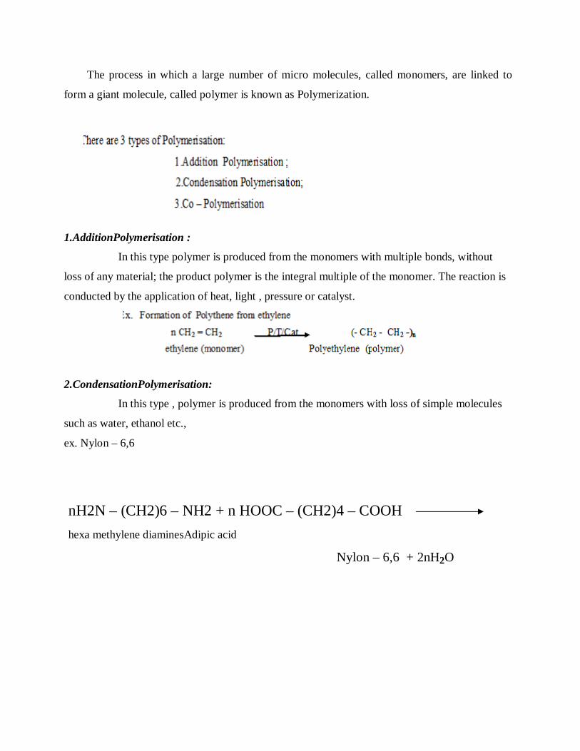
2.CondensationPolymerisation:
In this type , polymer is produced from the monomers with loss of simple molecules
such as water, ethanol etc.,
ex. Nylon – 6,6
nH2N – (CH2)6 – NH2 + n HOOC – (CH2)4 – COOH hexa methylene diaminesAdipic acid
Nylon – 6,6 + 2nH2O

3. CopolymerisationPolymerisation:
Here two different type of monomers [ one is aliphatic & the other is
aromatic ] combine to give polymers;
Ex. Butadiene and styrene gives Buna –S – rubber OR
Polybutadiene –co - styrene
DIFFERENCES BETWEEN ADDITION AND CONDENSATION POLYMERIZATION
S.No Addition Polymerization. Condensation Polymerization.
1. Monomers combine to form polymers without elimination.
Monomers combine to form polymers with elimination.( few exceptions )
2. Monomers must have at least one multiple bond ; ex. CH2 =CH2
Monomers must have at least two identical or different functional groups; ex. CH2 OH– CH2OH

H2N(CH2)4-COOH
3. No other by product is formed. By product such as H2S , HCl , etc., are formed.
4. M.wt. of the polymer is an integral multiple of M.Wt. of the monomer.
M.wt. of the polymer need not be an integral multiple of M.Wt. of the monomer.
5. High m.wt. polymer is formed at once M.Wt. of polymer increases steadily.
6. Longer reaction time give higher yield ; but no effect on M.Wt.
Longer reaction times are essential to get high M.Wt. Polymer.
7. Homo- chain polymer is obtained. Hetro - chain polymer is obtained.
8. Thermo plastics are produced. ex. PVC , polyethylene ,
Thermosetting plastics are produced. Ex. Bakelite , Polyester,
FREE – RADICAL MECHANISM OF POLYMERIZATION.
The free radical mechanism occurs in three major steps:
1.Initiation
2.Propagation
3.Termination
I.Initiation :
This involves two reactions :
(i)First reaction
involves production of free radical by hemolytic dissociation of an initiator ( or
catalyst ):
(ii ) Second reaction :
Addition of the free radical with the first monomer to give chain initiating
species :
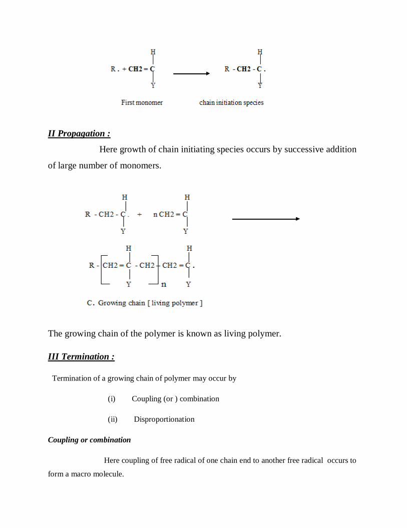
II Propagation :
Here growth of chain initiating species occurs by successive addition
of large number of monomers.
The growing chain of the polymer is known as living polymer.
III Termination :
Termination of a growing chain of polymer may occur by
(i) Coupling (or ) combination
(ii) Disproportionation
Coupling or combination
Here coupling of free radical of one chain end to another free radical occurs to
form a macro molecule.

Disproportionation :
Here transfer of hydrogen from one radical to another radical occurs to form
two macromolecules, one is saturated and the other is unsaturated.
The products of addition polymerisation is known as Dead Polymers.

PREPARATION, PROPERTIES AND USES OF THE POLYMERS
a) PVC ; b) Teflon ; c ) PET; d ) nylon 6-6
a) PVC
Preparation: This involves two steps :
In the Step – I vinyl chloride is formed from acetylene
Step II :
By heating water emulsion of vinyl chloride in the presence of H2O2 or benzoylperoxide under
pressure
Properties of PVC :
1.colourless , odourless
2.chemically inert powder
3. insoluble in inorganic & alkalis but soluble in hot chlorinated hydrocarbons
like ethyl chloride.
4. Undergoes degradation in the presence of light or heat.
uses :
1. production of pipes, cable insulators ,table covers & rain coats
2. for making sheets which are employed for light fittings ,
3. Refrigerator components, etc.,
b)Teflon :
Preparation :
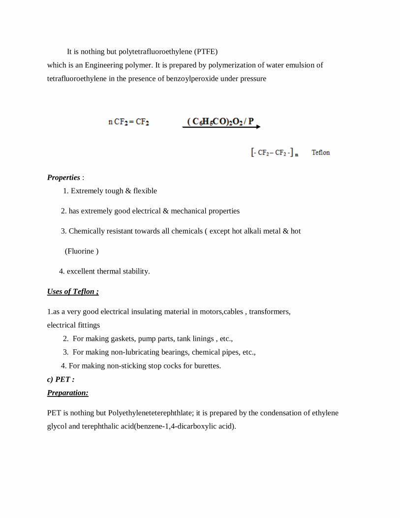
It is nothing but polytetrafluoroethylene (PTFE)
which is an Engineering polymer. It is prepared by polymerization of water emulsion of
tetrafluoroethylene in the presence of benzoylperoxide under pressure
Properties :
1. Extremely tough & flexible
2. has extremely good electrical & mechanical properties
3. Chemically resistant towards all chemicals ( except hot alkali metal & hot
(Fluorine )
4. excellent thermal stability.
Uses of Teflon ;
1.as a very good electrical insulating material in motors,cables , transformers,
electrical fittings
2. For making gaskets, pump parts, tank linings , etc.,
3. For making non-lubricating bearings, chemical pipes, etc.,
4. For making non-sticking stop cocks for burettes.
c) PET :
Preparation:
PET is nothing but Polyethyleneteterephthlate; it is prepared by the condensation of ethylene
glycol and terephthalic acid(benzene-1,4-dicarboxylic acid).
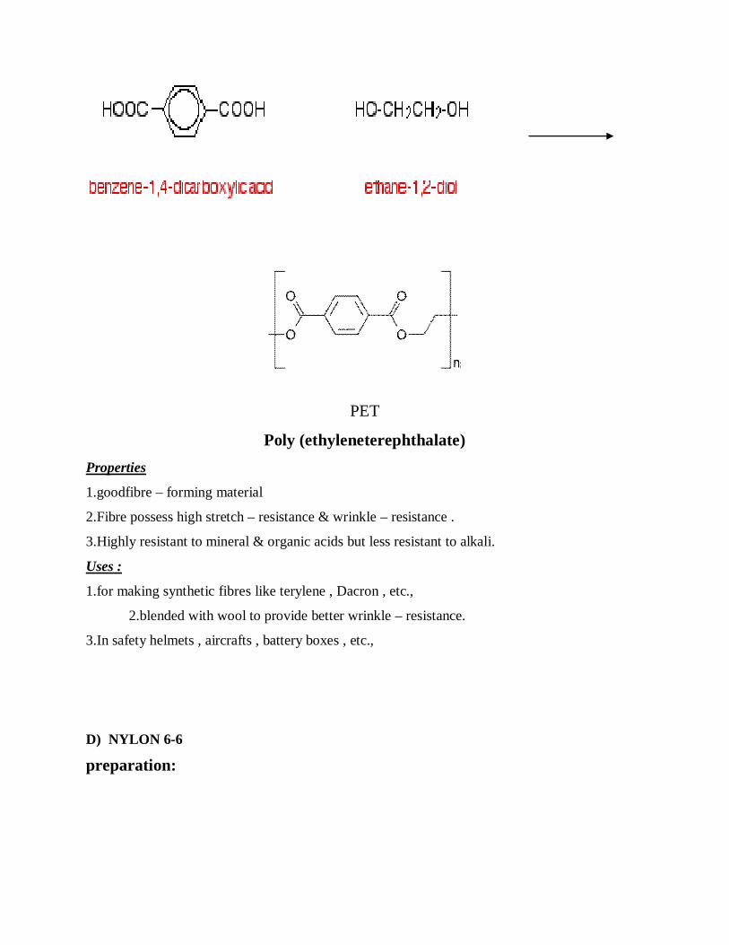
PET
Poly (ethyleneterephthalate) Properties
1.goodfibre – forming material
2.Fibre possess high stretch – resistance & wrinkle – resistance .
3.Highly resistant to mineral & organic acids but less resistant to alkali.
Uses :
1.for making synthetic fibres like terylene , Dacron , etc.,
2.blended with wool to provide better wrinkle – resistance.
3.In safety helmets , aircrafts , battery boxes , etc.,
D) NYLON 6-6
preparation:

it is an engineering plastic obtained by the condensation polymerization of 1 , 6 –
hexamethylenediamine with adipic acid . 6,6 indicates the number of carbon atoms
in each monomer.
Properties:
1. Nylons are transparent, whitest and high melting polymers.
2. Possess high temperature stability and good abrasion – resistance.
3. Insoluble in common organic solvents and soluble in phenol and formic acid.
Uses:
1. For making filaments for ropes , bristles for tooth –brushes , etc.,
2. Nylon 6 and nylon 11 are mainly used for moulding purposes for gears ,
bearings, etc.,
3. Forfibres, which is used in making socks , dresses , carpets, etc.,
PLASTICS Plastics are high molecular weight organic or inorganic materials, which can be moulded into any
stable form when subjected to heat and pressure in the presence of a catalyst. The name plastics or
plastic materials in general is given to organic materials of high molecular mass, which can be
moulded into any desired form when subjected to heat and pressure in presence of catalysts.
Polymer resin is the basic binding material, which forms the major part of a plastic. In recent
years plastics have attained greater importance in every walk of life due to their unique properties.
Now, plastics substitute all engineering materials like wood, metal, glass etc because of their
special advantages over other conventional materials. Plastics are products of polymers
Plastics are classified into two types:
1. Thermoplastics
They are the resins which soften on heating and set on cooling. Therefore, they can
be remoulded any number of times and used. Example: Polythene, PVC, Nylon, etc.
2. Thermosetting plastics.
They are the resins which set on heating and cannot be resoftened. Hence, their scrap
cannot be reused. Examples: Phenol-formaldehyde resin (Bakelite), urea
formaldehyde resin, etc. The differences between two types of plastics arise mainly
due to the difference in their chemical structure.
Properties of Engineering plastics They possess
1. High abrasion resistance
2. High load bearing properties
3. Fairly good thermal stability
4. Light weight
5. Readilymoldable into complicated shapes
6. Rigidity
7. Dimensional stability
8. High performance properties which permit them to be used in the same
manner as metals, alloys and ceramics
DISADVANTAGES OF PLASTICS
1. Softness
2. Embrittlement at low temperature
3. Deformation under load
4. Low heat resistant
5. Combustibility
6. Tend to degrade upon exposure to heat and radiation
7. Non bio – degradable
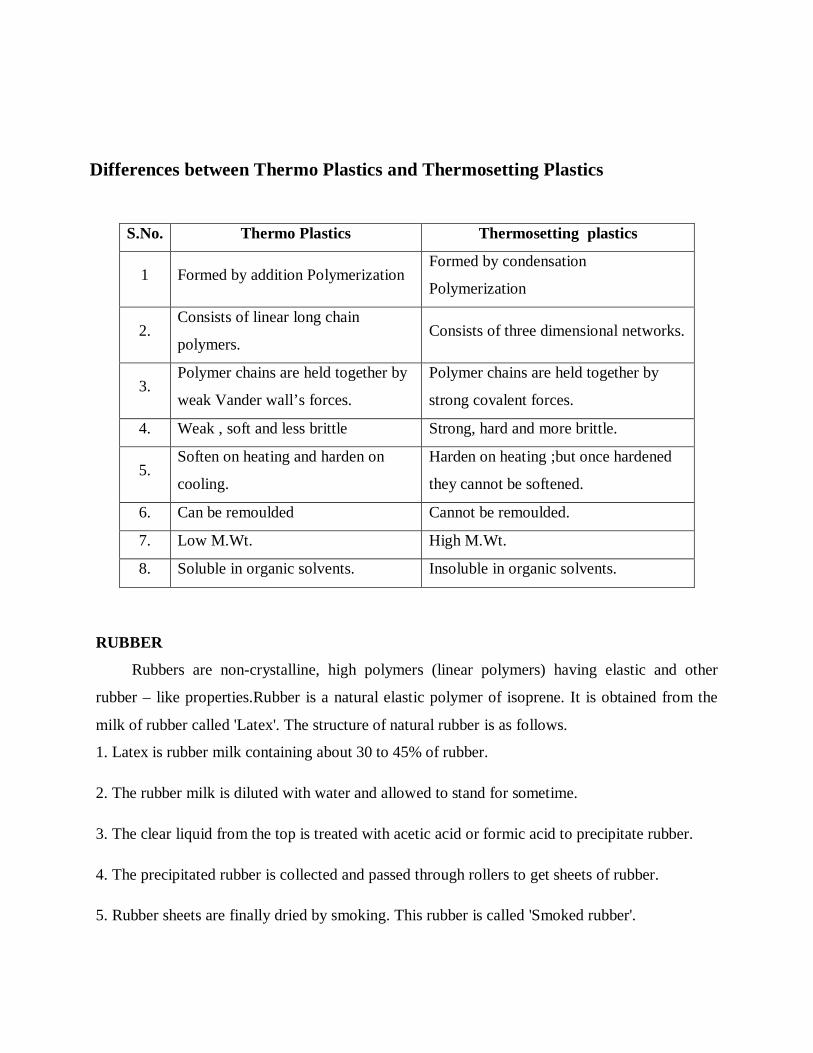
Differences between Thermo Plastics and Thermosetting Plastics
S.No. Thermo Plastics Thermosetting plastics
1 Formed by addition Polymerization Formed by condensation
Polymerization
2. Consists of linear long chain
polymers. Consists of three dimensional networks.
3. Polymer chains are held together by
weak Vander wall’s forces.
Polymer chains are held together by
strong covalent forces.
4. Weak , soft and less brittle Strong, hard and more brittle.
5. Soften on heating and harden on
cooling.
Harden on heating ;but once hardened
they cannot be softened.
6. Can be remoulded Cannot be remoulded.
7. Low M.Wt. High M.Wt.
8. Soluble in organic solvents. Insoluble in organic solvents.
RUBBER
Rubbers are non-crystalline, high polymers (linear polymers) having elastic and other
rubber – like properties.Rubber is a natural elastic polymer of isoprene. It is obtained from the
milk of rubber called 'Latex'. The structure of natural rubber is as follows.
1. Latex is rubber milk containing about 30 to 45% of rubber.
2. The rubber milk is diluted with water and allowed to stand for sometime.
3. The clear liquid from the top is treated with acetic acid or formic acid to precipitate rubber.
4. The precipitated rubber is collected and passed through rollers to get sheets of rubber.
5. Rubber sheets are finally dried by smoking. This rubber is called 'Smoked rubber'.
6. During the coagulation of rubber milk with acetic or formic acid, retardants like sodium
bisulphite (NaHSO) are added to prevent oxidation of rubber. This is called 'Creep rubber'.
The natural rubber obtained from latex cannot be used in industries because it has some defects.
1. It becomes soft and sticky during summer.
2. It became hard and brittle during winter.
3. It swells up in oils.
4. It flows plastically due to prolonged stress.
5. Chemicals easily affect rubber.
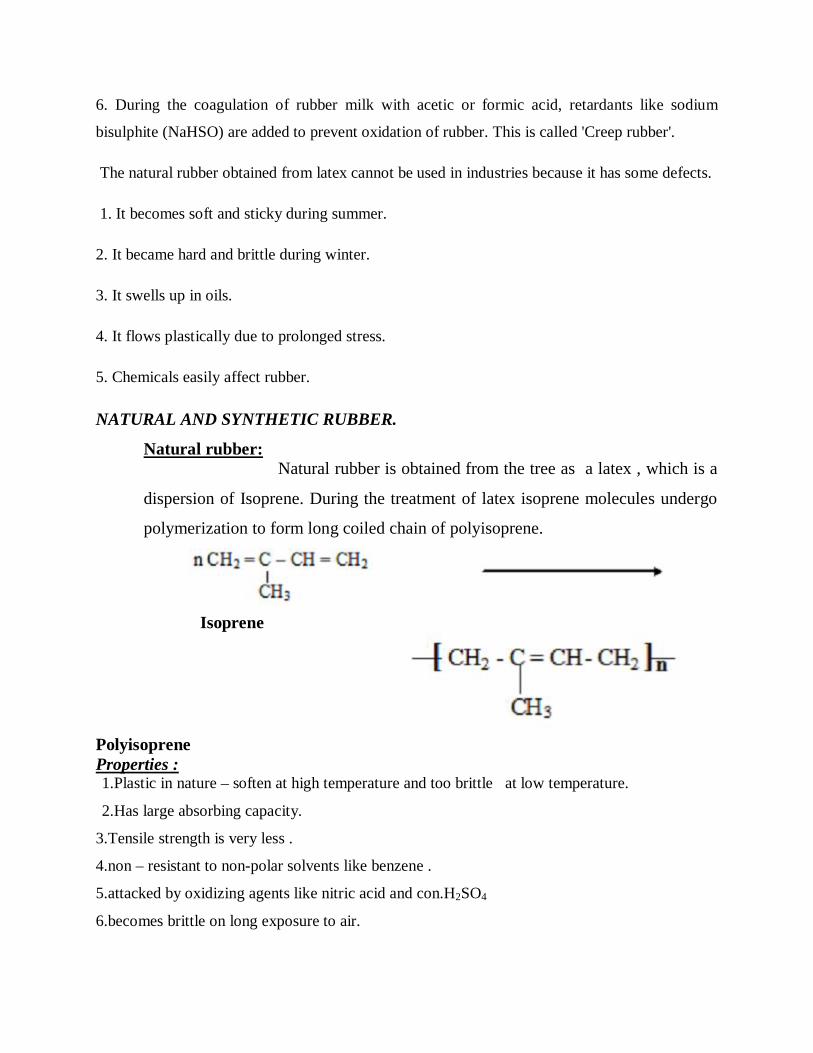
NATURAL AND SYNTHETIC RUBBER.
Natural rubber: Natural rubber is obtained from the tree as a latex , which is a
dispersion of Isoprene. During the treatment of latex isoprene molecules undergo
polymerization to form long coiled chain of polyisoprene.
Isoprene
Polyisoprene Properties : 1.Plastic in nature – soften at high temperature and too brittle at low temperature.
2.Has large absorbing capacity.
3.Tensile strength is very less .
4.non – resistant to non-polar solvents like benzene .
5.attacked by oxidizing agents like nitric acid and con.H2SO4
6.becomes brittle on long exposure to air.

To improve the properties of rubber, it is mixed with some chemicals like
sulphur , hydrogen sulphide etc. the properties of rubber improved using sulphur is called
vulcanisation.
SYNTHETIC RUBBER :
Synthetic rubber is nothing but any vulcanisable , manmade rubber like polymer ; it is
superior to natural rubber in certain properties.
Ex. Styrene Rubber (Buna – S rubber) or SBR;
It is prepared by copolymerization of Butadiene and Styrene
DRAWBACKS OF NATURAL RUBBER
1.plastic in nature – soften at high temperature and too brittle
at low temperature.
2.Has large absorbing capacity.
3.Tensile strength is very less .
4.non – resistant to non-polar solvents like benzene .
5.attacked by oxidizing agents like nitric acid and con. H2SO4
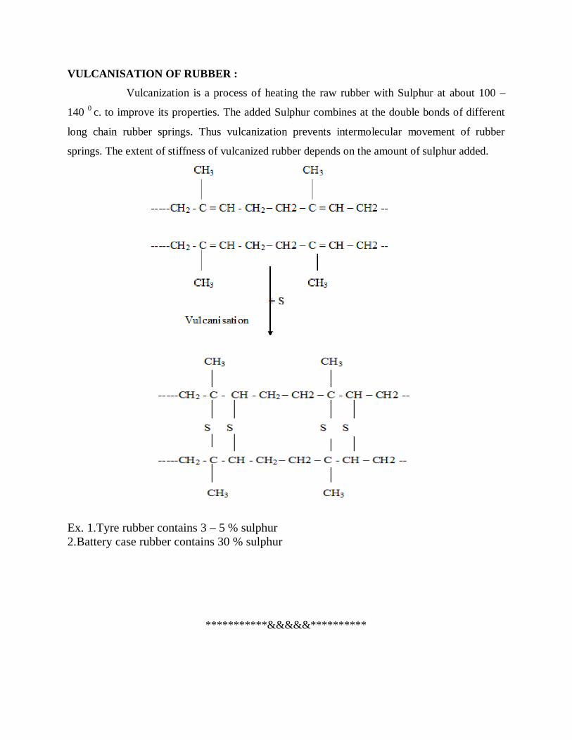
VULCANISATION OF RUBBER :
Vulcanization is a process of heating the raw rubber with Sulphur at about 100 –
140 0 c. to improve its properties. The added Sulphur combines at the double bonds of different
long chain rubber springs. Thus vulcanization prevents intermolecular movement of rubber
springs. The extent of stiffness of vulcanized rubber depends on the amount of sulphur added.
Ex. 1.Tyre rubber contains 3 – 5 % sulphur 2.Battery case rubber contains 30 % sulphur
***********&&&&&**********

BCH101 ENGINEERING CHEMISTRY- I
UNIT – III
ELECTRO CHEMISTRY
Electrochemistry is the branch of physical chemistry that studies the relationship
between electricity, as a measurable and quantitative phenomenon, and
identifiable chemical change, with either electricity considered an outcome of a particular
chemical change or vice versa. These reactions involve electric charges moving between
electrodes and an electrolyte (or ionic species in a solution). Thus electrochemistry deals
with the interaction between electrical energy and chemical change.
When a chemical reaction is caused by an externally supplied current, as
in electrolysis, or if an electric current is produced by a spontaneous chemical reaction as
in a battery, it is called an electrochemical reaction. Chemical reactions where electrons
are transferred directly between molecules and/or atoms are called oxidation-reduction or
(redox) reactions. In general, electrochemistry describes the overall reactions when
individual redox reactions are separate but connected by an external electric circuit and
an intervening electrolyte.
The term "redox" stands for reduction-oxidation. It refers to electrochemical
processes involving electron transfer to or from a molecule or ion changing its oxidation
state. This reaction can occur through the application of an external voltage or through
the release of chemical energy. Oxidation and reduction describe the change of oxidation
state that takes place in the atoms, ions or molecules involved in an electrochemical
reaction. Formally, oxidation state is the hypothetical charge that an atom would have if
all bonds to atoms of different elements were 100% ionic. An atom or ion that gives up

an electron to another atom or ion has its oxidation state increase, and the recipient of the
negatively charged electron has its oxidation state decrease.
Electrochemical reactions in water are better understood by balancing redox
reactions using the ion-electron method where H+, OH− ion, H2O and electrons (to
compensate the oxidation changes) are added to cell's half-reactions for oxidation and
reduction.
Acidic medium
In acid medium H+ ions and water are added to half-reactions to balance the
overall reaction. For example, when manganese reacts with sodium bismuthate.
Basic medium
In basic medium OH− ions and water are added to half reactions to balance the
overall reaction. For example, on reaction between potassium permanganate and sodium
sulfite
Neutral medium
The same procedure as used on acid medium is applied, for example on balancing
using electron ion method to complete combustion of propane
Electrochemical cells
An electrochemical cell is a device that produces an electric current from energy
released by a spontaneous redox reaction. This kind of cell includes the Galvanic cell or
Voltaic cell, named after Luigi Galvani and Alessandro Volta, both scientists who
conducted several experiments on chemical reactions and electric current during the late
18th century.
Electrochemical cells have two conductive electrodes (the anode and the cathode).
The anode is defined as the electrode where oxidation occurs and the cathode is the
electrode where the reduction takes place. Electrodes can be made from any sufficiently
conductive materials, such as metals, semiconductors, graphite, and even conductive
polymers. In between these electrodes is the electrolyte, which contains ions that can
freely move.
The galvanic cell uses two different metal electrodes, each in an electrolyte where
the positively charged ions are the oxidized form of the electrode metal. One electrode
will undergo oxidation (the anode) and the other will undergo reduction (the cathode).
The metal of the anode will oxidize, going from an oxidation state of 0 (in the solid form)
to a positive oxidation state and become an ion. At the cathode, the metal ion in solution
will accept one or more electrons from the cathode and the ion's oxidation state is
reduced to 0. This forms a solid metal that electrodeposits on the cathode. The two
electrodes must be electrically connected to each other, allowing for a flow of electrons
that leave the metal of the anode and flow through this connection to the ions at the
surface of the cathode. This flow of electrons is an electric current that can be used to do
work, such as turn a motor or power a light.
A galvanic cell whose electrodes are zinc and copper submerged in zinc
sulfate and copper sulfate, respectively, is known as a Daniell cell.
Half reactions for a Daniell cell are these
Zinc electrode (anode): Zn(s) → Zn2+(aq) + 2 e−
Copper electrode (cathode): Cu2+(aq) + 2 e− → Cu(s)
In this example, the anode is the zinc metal which is oxidized (loses electrons) to
form zinc ions in solution, and copper ions accept electrons from the copper metal
electrode and the ions deposit at the copper cathode as an electrodeposit. This cell forms
a simple battery as it will spontaneously generate a flow of electric current from the
anode to the cathode through the external connection. This reaction can be driven in
reverse by applying a voltage, resulting in the deposition of zinc metal at the anode and
formation of copper ions at the cathode.

To provide a complete electric circuit, there must also be an ionic conduction path
between the anode and cathode electrolytes in addition to the electron conduction path.
The simplest ionic conduction path is to provide a liquid junction. To avoid mixing
between the two electrolytes, the liquid junction can be provided through a porous plug
that allows ion flow while reducing electrolyte mixing. To further minimize mixing of the
electrolytes, a salt bridge can be used which consists of an electrolyte saturated gel in an
inverted U-tube. As the negatively charged electrons flow in one direction around this
circuit, the positively charged metal ions flow in the opposite direction in the electrolyte.
A voltmeter is capable of measuring the change of electrical potential between the anode
and the cathode.
Electrochemical cell voltage is also referred to as electromotive force or emf.
A cell diagram can be used to trace the path of the electrons in the electrochemical cell.
For example, here is a cell diagram of a Daniell cell:
Zn(s) | Zn2+ (1M) || Cu2+ (1M) | Cu(s)
First, the reduced form of the metal to be oxidized at the anode (Zn) is written.
This is separated from its oxidized form by a vertical line, which represents the limit
between the phases (oxidation changes). The double vertical lines represent the saline
bridge on the cell. Finally, the oxidized form of the metal to be reduced at the cathode, is
written, separated from its reduced form by the vertical line. The electrolyte
concentration is given as it is an important variable in determining the cell potential.
Reversible cell :
Here , the cell reactions will take place in the reverse direction , when the applied voltage
is greater than the cell voltage ; The voltage of the Daniel cell = 1.1V; Cell reaction ;
Cu + Zn 2+Cu 2+ + Zn
when the applied voltage is greater than the cell voltage , the cell reaction is
Cu 2+ + Zn Cu + Zn 2+
Ex. Daniel cell

Irreversible cell :
Here , the cell reactions cannot not be reversed by applying higher voltage greater than the
cell voltage. Ex., Dry cell
Standard electrode potential
To allow prediction of the cell potential, tabulations of standard electrode
potential are available. Such tabulations are referenced to the standard hydrogen electrode
(SHE). The standard hydrogen electrode undergoes the reaction
2 H+(aq) + 2 e− → H2
which is shown as reduction but, in fact, the SHE can act as either the anode or the
cathode, depending on the relative oxidation/reduction potential of the other
electrode/electrolyte combination. The term standard in SHE requires a supply of
hydrogen gas bubbled through the electrolyte at a pressure of 1 atm and an acidic
electrolyte with H+ activity equal to 1 (usually assumed to be [H+] = 1 mol/liter).
The SHE electrode can be connected to any other electrode by a salt bridge to form a
cell. If the second electrode is also at standard conditions, then the measured cell
potential is called the standard electrode potential for the electrode. The standard
electrode potential for the SHE is zero, by definition. The polarity of the standard
electrode potential provides information about the relative reduction potential of the
electrode compared to the SHE. If the electrode has a positive potential with respect to
the SHE, then that means it is a strongly reducing electrode which forces the SHE to be
the anode (an example is Cu in aqueous CuSO4 with a standard electrode potential of
0.337 V). Conversely, if the measured potential is negative, the electrode is more
oxidizing than the SHE (such as Zn in ZnSO4 where the standard electrode potential is
−0.76 V).
Standard electrode potentials are usually tabulated as reduction potentials. However,
the reactions are reversible and the role of a particular electrode in a cell depends on the

relative oxidation/reduction potential of both electrodes. The oxidation potential for a
particular electrode is just the negative of the reduction potential. A standard cell
potential can be determined by looking up the standard electrode potentials for both
electrodes (sometimes called half cell potentials). The one that is smaller will be the
anode and will undergo oxidation. The cell potential is then calculated as the sum of the
reduction potential for the cathode and the oxidation potential for the anode.
E°cell = E°red (cathode) – E°red (anode) = E°red (cathode) + E°oxi (anode)
For example, the standard electrode potential for a copper electrode is:
Cell diagram
Pt(s) | H2 (1 atm) | H+ (1 M) || Cu2+ (1 M) | Cu(s)
E°cell = E°red (cathode) – E°red (anode)
At standard temperature, pressure and concentration conditions, the
cell's emf (measured by a multimeter) is 0.34 V. By definition, the electrode potential for
the SHE is zero. Thus, the Cu is the cathode and the SHE is the anode giving
Ecell = E°(Cu2+/Cu) – E°(H+/H2)
Or,
E°(Cu2+/Cu) = 0.34 V
Changes in the stoichiometric coefficients of a balanced cell equation will not
change E°red value because the standard electrode potential is an intensive property
Spontaneity of redox reaction
During operation of electrochemical cells, chemical energy is transformed
into electrical energy and is expressed mathematically as the product of the cell's emf and
the electric charge transferred through the external circuit.
Electrical energy = EcellCtrans
where Ecell is the cell potential measured in volts (V) and Ctrans is the cell current
integrated over time and measured in coulombs (C); Ctrans can also be determined by
multiplying the total number of electrons transferred (measured in moles) times Faraday's
constant (F).
The emf of the cell at zero current is the maximum possible emf. It is used to
calculate the maximum possible electrical energy that could be obtained from a chemical
reaction. This energy is referred to as electrical work and is expressed by the following
equation:
Wmax = Welectrical = -nFEcell
where work is defined as positive into the system.
Since the free energy is the maximum amount of work that can be extracted from a
system, one can write:[23]
∆G = -nFEcell
A positive cell potential gives a negative change in Gibbs free energy. This is
consistent with the cell production of an electric current from the cathode to the anode
through the external circuit. If the current is driven in the opposite direction by imposing
an external potential, then work is done on the cell to drive electrolysis.
A spontaneous electrochemical reaction (change in Gibbs free energy less than
zero) can be used to generate an electric current in electrochemical cells. This is the basis
of all batteries and fuel cells. For example, gaseous oxygen (O2) and hydrogen (H2) can
be combined in a fuel cell to form water and energy, typically a combination of heat and
electrical energy.
Conversely, non-spontaneous electrochemical reactions can be driven forward by
the application of a current at sufficient voltage. The electrolysis of water into gaseous
oxygen and hydrogen is a typical example.
The relation between the equilibrium constant, K, and the Gibbs free energy for an
electrochemical cell is expressed as follows:
∆GO =-RT ln K=-nFEOcell
Rearranging to express the relation between standard potential and equilibrium constant
yields
EOcell =RTln K
nF
The previous equation can use Briggsian logarithm as shown below:
EO cell =0.0591V log K
n
Cell emf dependency on changes in concentration
Nernst’s equation


APPLICATIONS OF NERNST’S EQUATION
The applications of Nernst equation are
1. It can be used to calculate potential of an electrode;
2. Whether a reaction is feasible or not, can be decided;
3. Whether a metal can displace H2 from the acid solution can be determined ;
4. Equilibrium constant Keq. can be calculated.
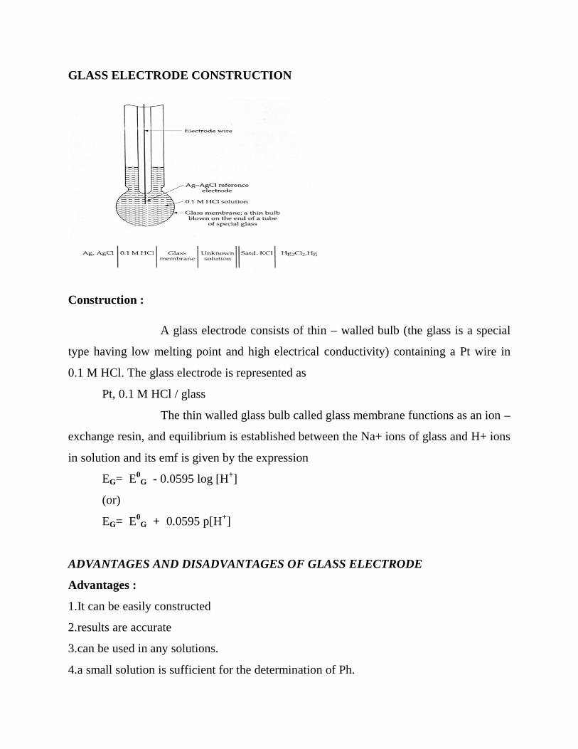
GLASS ELECTRODE CONSTRUCTION
Construction :
A glass electrode consists of thin – walled bulb (the glass is a special
type having low melting point and high electrical conductivity) containing a Pt wire in
0.1 M HCl. The glass electrode is represented as
Pt, 0.1 M HCl / glass
The thin walled glass bulb called glass membrane functions as an ion –
exchange resin, and equilibrium is established between the Na+ ions of glass and H+ ions
in solution and its emf is given by the expression
EG= E0G - 0.0595 log [H+]
(or)
EG= E0G + 0.0595 p[H+]
ADVANTAGES AND DISADVANTAGES OF GLASS ELECTRODE
Advantages :
1.It can be easily constructed
2.results are accurate
3.can be used in any solutions.
4.a small solution is sufficient for the determination of Ph.

Disadvantages :
1.it cannot be used in strong alkaline solution as it affects the glass.
2.special electronic potentiometer should be used for measurements.
GLASS ELECTRODE USED TO DETERMINE THE PH OF A SOLUTION
The glass electrode is placed in the solution under test and is coupled with
saturated calomel electrode as shown in the fig.
Electrode 1 is glass electrode and electrode 2 is calomel electrode; they are connected
through a potentiometer as shown in the diagram.
It is an internal reference electrode. The glass electrode &
calomel electrode are in touch with the test solution and connected to a potentiometer; the
emf of the cell is determined; then
E0G value is taken from the tables ; now ,in the equation [2] ,
EG and E0G are known ; so pH value can be determined.
Thus the pH of a given solution is determined using glass electrode.
STANDARD HYDROGEN ELECTRODE
Construction :
Hydrogen electrode consists of platinum foil connected to Pt wire and
sealed in a glass tube. Hydrogen gas is passed through the side arm of the glass tube. The
electrode is dipped in a 1N HCl and hydrogen gas at 1 atm. Pressure is passed at a temp.
of 250c . the electrode potential of SHE is zero at all temp.
It is represented as,
Pt, H2 (1atm.) / HCl(1M) ; E0 = 0 V
In a cell , when this acts as anode , electrode reaction can be written as,
H2 (g) 2H+ + 2e
when this acts as cathode , electrode reaction can be written as,
2H+ + 2e H2 (g)
CALOMEL ELECTRODE WITH A NEAT DIAGRAM.

Construction:
It consists of a glass tube containing Hg at the bottom ; above that Hg2Cl2
(calomel) paste is placed; above this saturated solution of KCl is taken.
The Pt wire is sealed in a glass tube and its bottom is in contact with Hg as shown
in the figure. The side tube is used for making electrical contact as salt bridge. The
electrode potential of saturated calomel electrode = 0.2422 V
It is represented as: Pt, Hg, Hg2Cl2(s)/ KCl (saturated)
If this electrode acts as anode, reaction is
2Hg (l) Hg2 2+ + 2e
If this electrode acts as cathode , reaction is
Hg2 2+ + 2e- 2Hg(s)
The potential of this electrode depends on the concentration of
Cl-& it decreases as the concentration of Cl– increases.
Its reduction potential is given by

E(0.1N.) = +0.3338 V ; E( 1N.) = +0.280 V ;
E( sat.) = +0.2422 V ;
EMF OF A GALVANIC CELL MEASURED BY POGGENDORFF’S
COMPENSATIONMETHOD
Principle :
The emf of a cell can is measured on the basis of Poggendorff’s compensation method.
Here the emf of the test cell is opposed and compensated by an external emf;
measurements are are made when there is no flow of current in the circuit ;ie emf of the
test cell is balanced ( ie., compensated ) by the external emf.
Circuit Diagram
Procedure :
Standard cell C1 and the test cell C2 are connected to a potentiometer
through a three way plug and also to a galvanometer G and a sliding contact J as shown
the circuit diagram.
At first the standard cell is connected & J is moved here and there until there
is no current flow in G; now the length

l1α C1
Then test cell is connected & J is moved here and there until there is no current flow in
G; now the length
l2 α C2
Hence , C2 /C1 = l2 /l1
C2 = l2 /l1 x C1
Since current C is directly proportional to emf E ,
So , E2 = E1 . l2 /l1
thus the emf of a cell is determined on the basis of Poggendorff’s
compensation method.
THE POTENTIOMETRIC TITRATION WITH A SPECIFIC EXAMPLE
The titration in which the end point is noted by the change in the potential
values of the solution .let us consider the titration between ferrous Ammonium Sulphate
(FAS) and K2Cr2O7 .
Principle:
The potential value of a solution depends on its concentration. During titration its
concentration changes gradually and so its potential value also changes gradually; at the
end point the change will be very sharp; after the end point the change will not be
appreciable.
Let us consider the titration of FAS Vs K2Cr2O7
In the titration at the beginning there are only F2+ ions and no Fe3+ ions;
as the dichromate is added , the F2+ ions are oxidized in to Fe3+ ; the concentration of to
Fe3+ ions goes on increases ; so the potential value also goes on increases & at the end
point the emf value will be sharp; further addition will result no appreciable change in
emf value.
In the graph plotted drawn between EMF and volume of K2Cr2O7 , the emf
goes on increases gradually as shown ; at the end point all the ions are completely
oxidized in to Fe3+ ; so sharp increase results ; further the graph is almost horizontal .
The line which is almost perpendicular, gives the value of dichromate necessary for the
end point; from this the strength and hence amount of FAS in the whole of the given
solution can be calculated
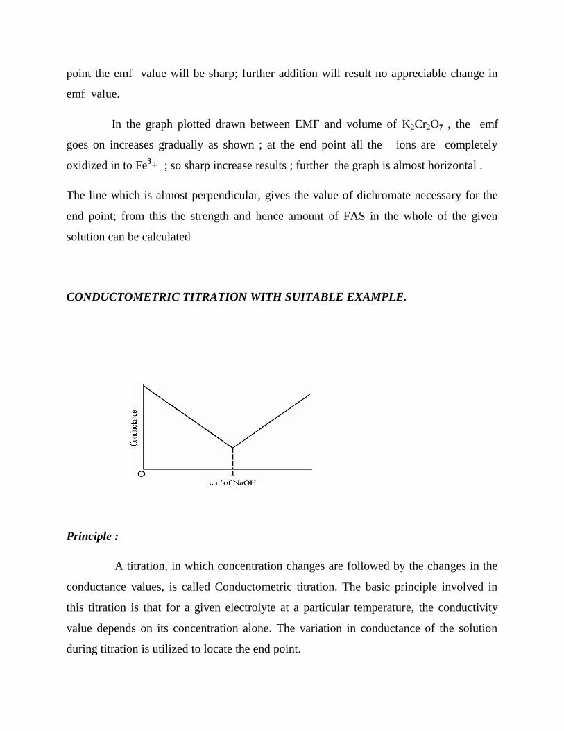
CONDUCTOMETRIC TITRATION WITH SUITABLE EXAMPLE.
Principle :
A titration, in which concentration changes are followed by the changes in the
conductance values, is called Conductometric titration. The basic principle involved in
this titration is that for a given electrolyte at a particular temperature, the conductivity
value depends on its concentration alone. The variation in conductance of the solution
during titration is utilized to locate the end point.
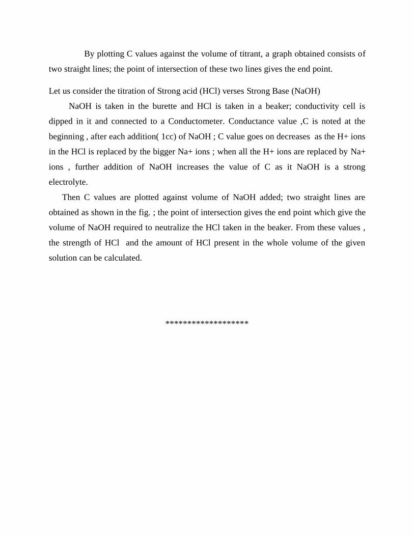
By plotting C values against the volume of titrant, a graph obtained consists of
two straight lines; the point of intersection of these two lines gives the end point.
Let us consider the titration of Strong acid (HCl) verses Strong Base (NaOH)
NaOH is taken in the burette and HCl is taken in a beaker; conductivity cell is
dipped in it and connected to a Conductometer. Conductance value ,C is noted at the
beginning , after each addition( 1cc) of NaOH ; C value goes on decreases as the H+ ions
in the HCl is replaced by the bigger Na+ ions ; when all the H+ ions are replaced by Na+
ions , further addition of NaOH increases the value of C as it NaOH is a strong
electrolyte.
Then C values are plotted against volume of NaOH added; two straight lines are
obtained as shown in the fig. ; the point of intersection gives the end point which give the
volume of NaOH required to neutralize the HCl taken in the beaker. From these values ,
the strength of HCl and the amount of HCl present in the whole volume of the given
solution can be calculated.
*******************
BCH101 ENGINEERING CHEMISTRY- I
UNIT – IV
CORROSION AND CORROSION CONTROL
Corrosion can be defined as the
gradual destruction of materials, (usually metals), by the chemical or electrochemical reaction
with its environment. Corrosion is the breakdown of materials due to reactions. It is
usually oxidation with air molecules and often in the presence of water. Corrosion also occurs
when an acidic or basic material touches another material. When a material corrodes, it changes
and becomes weaker. Materials that corrode include metal, plastic, and wood. Also, corrosion is
a form of erosion.
One form of high temperature corrosion can lead to the formation of compacted oxide
layer glazes, which under certain circumstances reduces wear.Iron corrosion is called rusting.
Corrosion is a natural process, which converts a refined metal to a more chemically-stable form,
such as its oxide, hydroxide, or sulfide. It is the gradual destruction of materials (usually metals)
by chemical and/or electrochemical reaction with their environment. Corrosion engineering is the
field dedicated to controlling and stopping corrosion.
In the most common use of the word, this means electrochemical oxidation of metal in
reaction with an oxidant such as oxygen or sulfur. Rusting, the formation of iron oxides, is a
well-known example of electrochemical corrosion. This type of damage typically
produces oxide(s) or salt(s) of the original metal, and results in a distinctive orange colouration.
Corrosion can also occur in materials other than metals, such as ceramics or polymers, although
in this context, the term "degradation" is more common. Corrosion degrades the useful properties
of materials and structures including strength, and permeability to liquids and gases.
PILLING –BEDWORTH RULE

According to this rule if the volume of the oxide film formed is at least as large as the volume of
the metal consumed , the oxide layer is protective or nonporous ; on the other hand , if the
volume of the oxide is less than the volume of the metal consumed , the layer will be porous or
non-protective
The Pilling–Bedworth ratio (P–B ratio), in corrosion of metals, is the ratio of the
volume of the elementary cell of a metal oxide to the volume of the elementary cell of the
corresponding metal (from which the oxide is created).On the basis of the P–B ratio, it can be
judged if the metal is likely to passivate in dry air by creation of a protective oxide layer.
MECHANISM OF CORROSION
[1] Chemical Corrosion
1. Chemical corrosion simply involves reaction between chemicals and materials ; it occurs
due to the attack of the metal surfaces by atmospheric gases such as oxygen , nitrogen ,
hydrogen sulphide ,sulphurdioxide , etc.,

iii) M2+ andO2- react to form metal oxide film on the surface .
M + 1/2 O2 MO
Once the metal surface is converted to a monolayer of metal oxide , the metal ion diffuses
outward through metal oxide film for further corrosion to occur. Thus the growth of oxide film
commences perpendicular to the the metal. Surface .
If the oxide layer formed is non-porous &non-volatile ,it stops further O2
attack through diffusion. Such a film behaves as a protective coating; but if it is porous and
volatile , further corrosion occurs by diffusion or direct of oxygen in its ionic form with metal
ion.
[2] Mechanism of Electro chemical or wet Corrosion:
This type of corrosion occurs under the following conditions :
1. When two dissimilar metals are in contact with each other in the presence of moisture or
an aqueous solution.
2. When a metal is exposed to different concentration of O2 or electrolyte.
Under the above conditions, one part of the metal becomes anode and the another part becomes
cathode;
i) At anode :
Metal oxidizes to M2+
M M2+
ii) At cathode :
Here reduction occurs depending on the nature of corrosive environment:
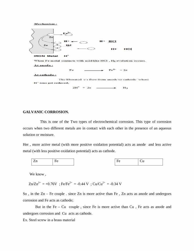
GALVANIC CORROSION.
This is one of the Two types of electrochemical corrosion. This type of corrosion
occurs when two different metals are in contact with each other in the presence of an aqueous
solution or moisture.
Her , more active metal (with more positive oxidation potential) acts as anode and less active
metal (with less positive oxidation potential) acts as cathode.
Zn Fe Fe Cu
We know ,
Zn/Zn2+ = +0.76V ; Fe/Fe2+ = -0.44 V ; Cu/Cu2+ = -0.34 V
So , in the Zn – Fe couple . since Zn is more active than Fe , Zn acts as anode and undergoes
corrosion and Fe acts as cathode;
But in the Fe – Cu couple , since Fe is more active than Cu , Fe acts as anode and
undergoes corrosion and Cu acts as cathode.
Ex. Steel screw in a brass material
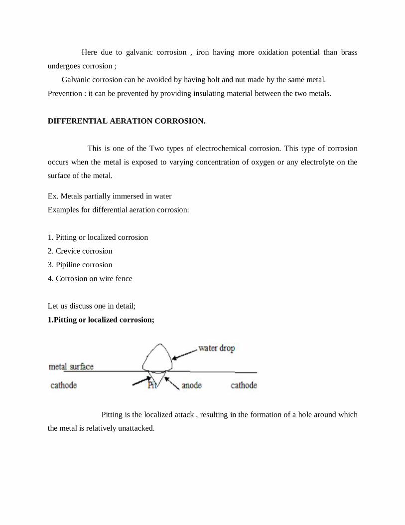
Here due to galvanic corrosion , iron having more oxidation potential than brass
undergoes corrosion ;
Galvanic corrosion can be avoided by having bolt and nut made by the same metal.
Prevention : it can be prevented by providing insulating material between the two metals.
DIFFERENTIAL AERATION CORROSION.
This is one of the Two types of electrochemical corrosion. This type of corrosion
occurs when the metal is exposed to varying concentration of oxygen or any electrolyte on the
surface of the metal.
Ex. Metals partially immersed in water
Examples for differential aeration corrosion:
1. Pitting or localized corrosion
2. Crevice corrosion
3. Pipiline corrosion
4. Corrosion on wire fence
Let us discuss one in detail;
1.Pitting or localized corrosion;
Pitting is the localized attack , resulting in the formation of a hole around which
the metal is relatively unattacked.

Let us consider a drop of water resting on a metal surface as shown in the fig. the area covered
by the drop of water acts as anode due to less oxygen concentration and suffers corrosion. The
uncovered area freely exposed to air, acts as cathode due to high oxygen concentration.
Rate of corrosion will be more , when the area of the cathode is larger and the area of anode is
smaller. Therefore , more and more material is removed from the same spot. Thus a small hole or
pit I formed on the surface of the metal.
This type of intense corrosion
is called pitting.
CREVICE CORROSION
Crevice corrosion is a localized form of corrosion occurring in confined spaces (crevices), to
which the access of the working fluid from the environment is limited. Formation of a
differential aeration cell leads to corrosion inside the crevices. Examples of crevices are gaps and
contact areas between parts, under gaskets or seals, inside cracks and seams, spaces filled with
deposits and under sludge piles.
Crevice corrosion is influenced by the crevice type (metal-metal, metal-nonmetal), crevice
geometry (size, surface finish), and metallurgical and environmental factors. The susceptibility to
crevice corrosion can be evaluated with ASTM standard procedures. A critical crevice corrosion
temperature is commonly used to rank a material's resistance to crevice corrosion.
FACTORS INFLUENCING THE CORROSION.
1.Nature of the metal ;
2.Nature of environment ;
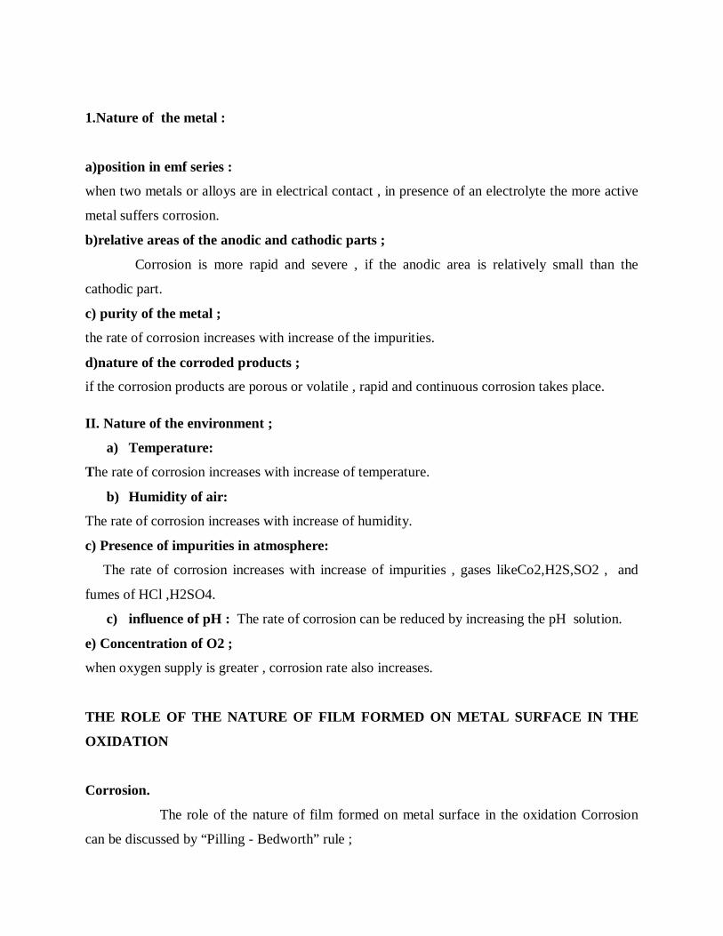
1.Nature of the metal :
a)position in emf series :
when two metals or alloys are in electrical contact , in presence of an electrolyte the more active
metal suffers corrosion.
b)relative areas of the anodic and cathodic parts ;
Corrosion is more rapid and severe , if the anodic area is relatively small than the
cathodic part.
c) purity of the metal ;
the rate of corrosion increases with increase of the impurities.
d)nature of the corroded products ;
if the corrosion products are porous or volatile , rapid and continuous corrosion takes place.
II. Nature of the environment ;
a) Temperature:
The rate of corrosion increases with increase of temperature.
b) Humidity of air:
The rate of corrosion increases with increase of humidity.
c) Presence of impurities in atmosphere:
The rate of corrosion increases with increase of impurities , gases likeCo2,H2S,SO2 , and
fumes of HCl ,H2SO4.
c) influence of pH : The rate of corrosion can be reduced by increasing the pH solution.
e) Concentration of O2 ;
when oxygen supply is greater , corrosion rate also increases.
THE ROLE OF THE NATURE OF FILM FORMED ON METAL SURFACE IN THE
OXIDATION
Corrosion.
The role of the nature of film formed on metal surface in the oxidation Corrosion
can be discussed by “Pilling - Bedworth” rule ;

According to that rule ,
If the volume of the oxide film formed is less than the volume of the metal corroded
, the oxide layer is porous and non- protective ;
Ex. The volumes of the oxides of alkali and alkaline earth metals , such as Na , Mg , ca , etc.,
is less than the volume of the metal consumed. Hence the oxide layer formed is porous and non-
protective.
If the volume of the oxide film formed is greater than the volume of the metal
corroded , the oxide layer is non-porous and protective ;
Ex. The volumes of the oxides of heavy metals , such as Pb , Sn , etc., is greater than the
volume of the metal consumed. Hence the oxide layer formed is non- porous and protective.
CORROSION CONTROL BY
a) Sacrificial anodic protection method
b) Impressed current cathodic protection method
a) Sacrificial anodic protection method
In this method the metal to be protected is connected to more anodic ( active ) metal by a
wire . the more active metal itself gets corroded slowly , while the parent structure is protected.
The more active metal used , is called Sacrificial anode. Metals commonly employed as
Sacrificial anodes are Mg , Zn , Al ,and their alloys.
Application :
1.ships hull ; 2.marine equipments ; 3. Water tanks
b)Impressed current cathodic protection method.
In this method , an impressed (direct) current is applied in the opposite direction of the
corrosion current to nullify it .
In this method , the metal to be protected converted to cathode by connecting to the
negative terminal of the battery. The positive terminal of the battery is connected to an inert
anode. The inert anodes used for this purpose are graphite ,platinised titanium. The anode is

buried in a “back fill ”It is a mixture of gypsum , coke , breeze , sodium sulphate; it provides
good electrical contact to anode.
ELECTROPLATING
Electroplating is a process by which the coating metal is deposited on the base metal by
passing a direct current through an electrolyte solution containing the soluble salt of the coating
metal.
ELECTROLESS PLATING
The surface of the plate is first degreased using organic solvents or alkali followed by acid
treatment; then they are dipped in different solutions to activate the surface.
DIFFERENCES BETWEEN ELECTROPLATING AND ELECTROLESS PLATING
S.N
O.
ELECTRO PLATING ELECTROLESS PLATING
1. It is carried out by passing current It is carried out By auto catalytic
redox reactio
2. Separate anode is employed Catalytic surface acts as anode
3. Anode reaction
M --------- Mn+ + ne
Anode reaction
R --------- O + ne
4. Cathodic reaction
Mn+ + ne ---------- M
Cathodic reaction
Mn+ + ne ---------- M
5. Not satisfactory for objects with irregular
shape.
satisfactory for all objects even
with irregular shape.
6. It is carried out on conducting materials. It is carried out on conducting ,
semiconducting (plastics)materials.
7. Thickness of the plating is 1 – 100 µm Thickness of the plating is 1 – 100
µm

A) ELECTROPLATING OF GOLD OVER COPPER OBJECT
B) ELECTROLESS PLATING OF NICKEL
a) Electroplating of gold over copper object .
The electroplating is the process by which the coating metal is
deposited on the base metal by passing a direct current through an electrolytic solution
containing the soluble salt of the coating metal.
The base metal to be plated is made cathode of an electrolytic cell and anode is either made of
coating metal itself or an inert metal of good electrical conductivity.
THEORY :
If the anode is made of coating metal itself , the concentration of the electrolyte remains
unaffected during electrolysis; since metal ions deposited from solution on cathode , are replaced
continuously by the reaction of free negative ions with anode.
PROCESS :
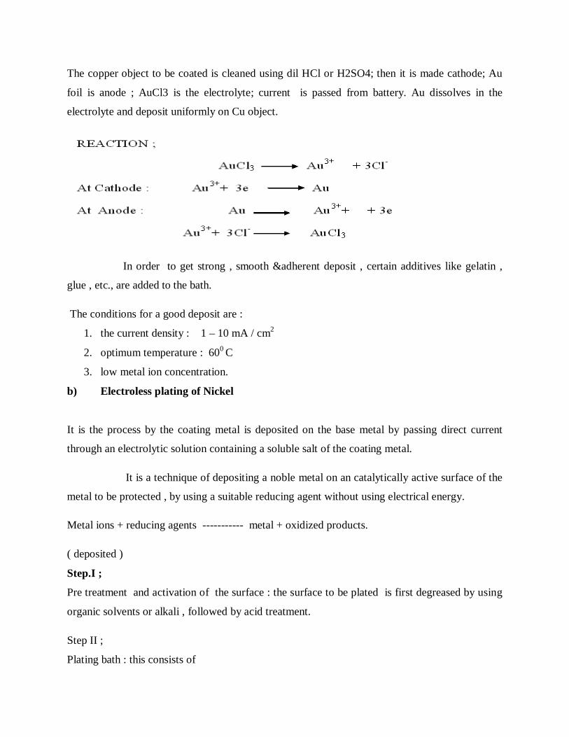
The copper object to be coated is cleaned using dil HCl or H2SO4; then it is made cathode; Au
foil is anode ; AuCl3 is the electrolyte; current is passed from battery. Au dissolves in the
electrolyte and deposit uniformly on Cu object.
In order to get strong , smooth &adherent deposit , certain additives like gelatin ,
glue , etc., are added to the bath.
The conditions for a good deposit are :
1. the current density : 1 – 10 mA / cm2
2. optimum temperature : 600 C
3. low metal ion concentration.
b) Electroless plating of Nickel
It is the process by the coating metal is deposited on the base metal by passing direct current
through an electrolytic solution containing a soluble salt of the coating metal.
It is a technique of depositing a noble metal on an catalytically active surface of the
metal to be protected , by using a suitable reducing agent without using electrical energy.
Metal ions + reducing agents ----------- metal + oxidized products.
( deposited )
Step.I ;
Pre treatment and activation of the surface : the surface to be plated is first degreased by using
organic solvents or alkali , followed by acid treatment.
Step II ;
Plating bath : this consists of

1. coating solution – NiCl2
2. reducing agent - sodium hypophosphite
3. complexing agent – sodium succinate
4. buffer – sodium acetate
5. optimum ph – 4.5
6. optimum temperature - 930 C
Step III ;Procedure ;
The pre - treated object is immersed in the plating bath for the required time. During
which the following reduction reaction will occur and the Ni gets coated over the object. The
reducing agent provides electrons for reduction ,
H2PO2- + H2O H2PO3
-- + 2 H + + 2e
At cathode : Ni+2 + 2e Ni
THE CONSTITUENTS OF PAINTS AND THEIRFUNCTIONS.
Paint can be defined as a mixture consisting of a solid pigment or pigments
suspended in a medium (mixture of vehicle and thinner) , that when applied to a surface dries to
form a hard coating.
THE FUNCTION OF PIGMENT IN A PAINT
Pigments are solid and colour producing substances in the paint. Its functions are
1.it gives colour and opacity to the film
2.also provides strength to the film
3.protects the film by reflecting the destructive UV rays.
THE CONSTITUENTS OF PAINTS AND THEIR FUNCTIONS:
1. Pigment :
these are solids and colour producing substances in the paint.
Function :

1. It gives colour and opacity to the film.
2. It also provides the strength to the film.
2.Vehicle or drying oil ;
This is the non- volatile portion of the medium. This is the film forming constituent of the paint.
Function :
1. they form a protective film by the oxidation and polymerization of the oil.
2. They hold the pigment particle together on the metal surface.
3. Thinner or solvent
This is a volatile portion of the medium; it easily evaporates after application of a paint.
Function :
1. Reduces the viscosity of the paint
2. Increases the elasticity of the film
3. Increases the penetrating power of the vehicle.
4. Extender or Filler
They are white or colourless pigments.
Function :
1. Reduces the cost of the paint.
2. Modifies the shades of the paint
3. Prevents the shrinkage and cracking
5.Driers : They are the substances , used to accelerate the process of drying.
Function ;
1. They act as oxygen – carrier or catalysts
2. Provide oxygen , which is essential for oxidation
6.Plasticisers :
They are chemicals added to the paints to provide elasticity to the film and to prevent the
cracking of the film .
7.anti-skinning agents :
These are chemicals added to the paints to prevent gelling and skinning of the paint.
**********

BCH101 ENGINEERING CHEMISTRY- I
UNIT – V
NON – CONVENTIONAL ENERGY SOURCES
NUCLEAR FISSION
It can be defined as “the process of splitting of heavier nuclei nucleus into two or
more smaller nuclei with simultaneous liberation of large amount of energy.” It is always
accompanied by two or more neutrons.
NUCLEAR FUSION
It can be defined as “the process of combination of lighter nuclei into heavier nuclei,
with simultaneous liberation of large amount of energy. ”
ENERGY LOSS IN A NUCLEAR CHAIN REACTION
Some of the neutrons released in the nuclear chain reaction may escape from the
surface to the surrounding o may be absorbed by U238 present as impurity. This will result
in breaking of the chain and the amount of energy released will be less than expected; this
less in energy is called Energy loss in a nuclear chain reaction.
(A)NUCLEAR ENERGY CRITICAL MASS .(B) SUPER CRITICAL MASS .
(a)Nuclear Energy Critical mass .
The minimum amount of fissionable material required to continue the nuclear
chain reaction is called Critical Mass.
(b) Super Critical mass .
If the amount of fissionable material is more than the Critical Mass , it is called
Super Critical mass.
(c) Sub -critical mass:
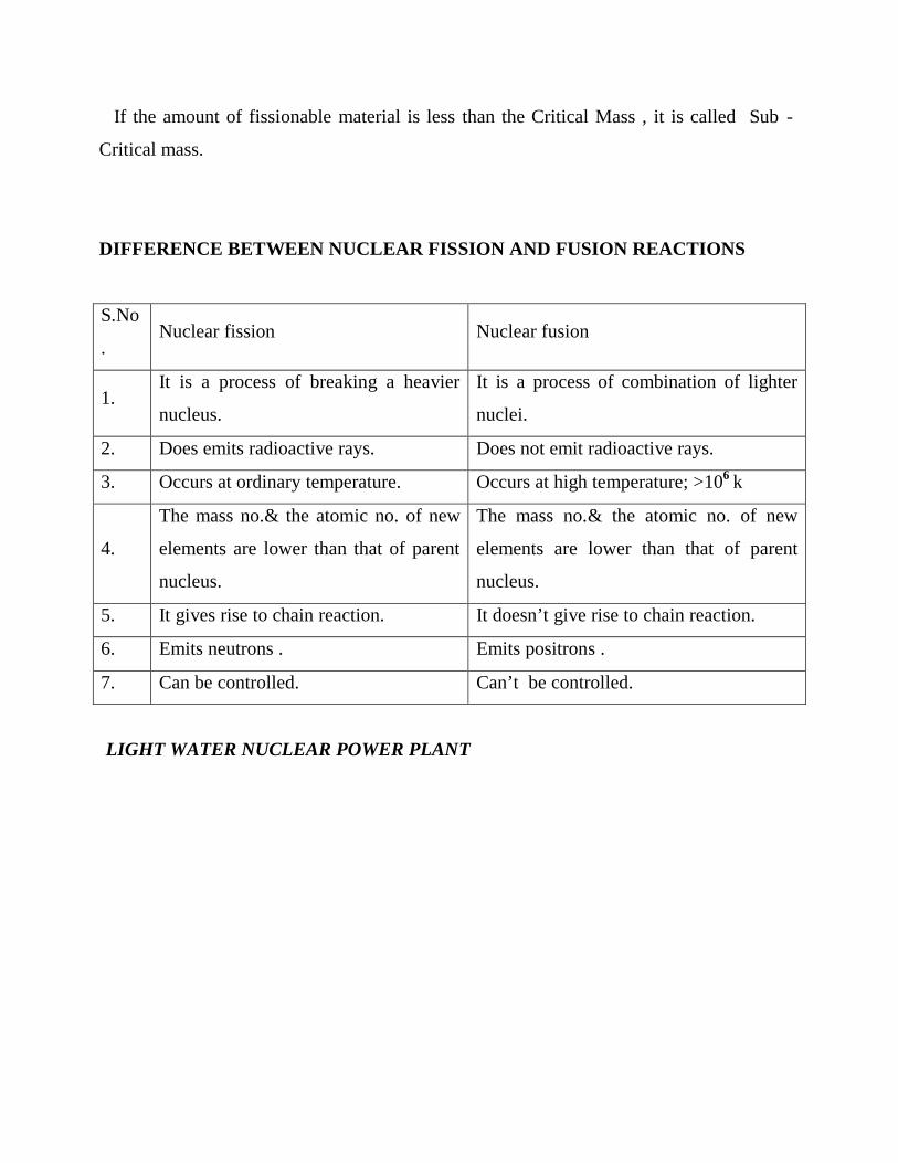
If the amount of fissionable material is less than the Critical Mass , it is called Sub -
Critical mass.
DIFFERENCE BETWEEN NUCLEAR FISSION AND FUSION REACTIONS
S.No
. Nuclear fission Nuclear fusion
1. It is a process of breaking a heavier
nucleus.
It is a process of combination of lighter
nuclei.
2. Does emits radioactive rays. Does not emit radioactive rays.
3. Occurs at ordinary temperature. Occurs at high temperature; >106 k
4.
The mass no.& the atomic no. of new
elements are lower than that of parent
nucleus.
The mass no.& the atomic no. of new
elements are lower than that of parent
nucleus.
5. It gives rise to chain reaction. It doesn’t give rise to chain reaction.
6. Emits neutrons . Emits positrons .
7. Can be controlled. Can’t be controlled.
LIGHT WATER NUCLEAR POWER PLANT

LWNP Plant is the one in which U235 fuel rods are submerged in H2O; here water act as
coolant and moderator.
CONTROL ROD
Control rods are usually combined into control rod assemblies — typically 20 rods for a
commercial pressurized water reactor assembly — and inserted into guide tubes within a
fuel element. A control rod is removed from or inserted into the central core of a nuclear
reactor in order to control the number of neutrons which will split further uranium atoms.
This in turn affects the thermal power of the reactor, the amount of steam generated, and
hence the electricity produced. The control rods are partially removed from the core to
allow a chain reaction to occur. The number of control rods inserted and the distance by
which they are inserted can be varied to control the reactivity of the reactor.
COOLANT
Nuclear reactor coolant

The light-water reactor also uses ordinary water to keep the reactor cooled. The cooling
source, light water, is circulated past the reactor core to absorb the heat that it generates.
The heat is carried away from the reactor and is then used to generate steam. Most reactor
systems employ a cooling system that is physically separate from the water that will be
boiled to produce pressurized steam for the turbines, like the pressurized-water reactor.
But in some reactors the water for the steam turbines is boiled directly by the reactor
core, for example the boiling-water reactor.
Many other reactors are also light-water cooled, notably the RBMK and some
military plutonium-production reactors. These are not regarded as LWRs, as they are
moderated by graphite, and as a result their nuclear characteristics are very different.
Although the coolant flow rate in commercial PWRs is constant, it is not in nuclear
reactors used on U.S. Navyships.
FUEL
Nuclear fuel
The use of ordinary water makes it necessary to do a certain amount of enrichment of the
uranium fuel before the necessary criticality of the reactor can be maintained. The light-
water reactor uses uranium 235 as a fuel, enriched to approximately 3 percent. Although
this is its major fuel, the uranium 238 atoms also contribute to the fission process by
converting to plutonium 239; about one-half of which is consumed in the reactor. Light-
water reactors are generally refueled every 12 to 18 months, at which time, about 25
percent of the fuel is replaced.
MODERATOR
Neutron moderator
A neutron moderator is a medium which reduces the velocity of fast neutrons, thereby
turning them into thermal neutrons capable of sustaining a nuclear chain reaction
involving uranium-235. A good neutron moderator is a material full of atoms with light

nuclei which do not easily absorb neutrons. The neutrons strike the nuclei and bounce off.
After sufficient impacts, the velocity of the neutron will be comparable to the thermal
velocities of the nuclei; this neutron is then called a thermal neutron.
The light-water reactor uses ordinary water, also called light water, as its neutron
moderator. The light water absorbs too many neutrons to be used with enriched natural
uranium, and therefore uranium enrichment or nuclear reprocessing becomes necessary to
operate such reactors, increasing overall costs. This differentiates it from a heavy water
reactor, which uses heavy water as a neutron moderator. While ordinary water has some
heavy water molecules in it, it is not enough to be important in most applications. In
pressurized water reactors the coolant water is used as a moderator by letting the neutrons
undergo multiple collisions with light hydrogen atoms in the water, losing speed in the
process. This moderating of neutrons will happen more often when the water is denser,
because more collisions will occur.
WORKING:-
The fission reaction is controlled by inserting or removing the control rods B10 or
Cd113from the space between fuel rods.
The heat emitted by fission of U 235 is absorbed by the coolant; the heated coolant [at
3000c ] then goes to the heat-exchanger containing sea water . The coolant here, transfers
heat to sea water, which is converted it into steam; the steam then drives the turbines,
generating electricity.
SOLAR ENERGY CONVERSION
Solar energy conversion is the process of conversion of direct sun light into
more useful forms. This conversion occurs by two mechanisms:
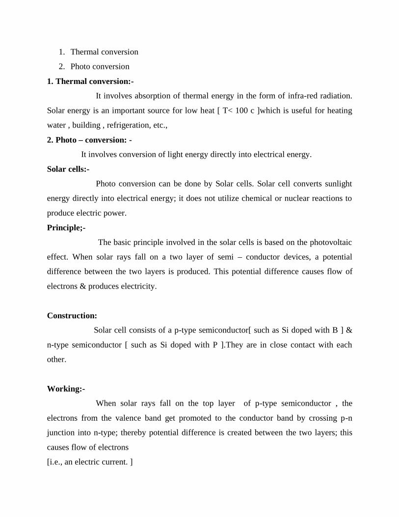
1. Thermal conversion
2. Photo conversion
1. Thermal conversion:-
It involves absorption of thermal energy in the form of infra-red radiation.
Solar energy is an important source for low heat [ T< 100 c ]which is useful for heating
water , building , refrigeration, etc.,
2. Photo – conversion: -
It involves conversion of light energy directly into electrical energy.
Solar cells:-
Photo conversion can be done by Solar cells. Solar cell converts sunlight
energy directly into electrical energy; it does not utilize chemical or nuclear reactions to
produce electric power.
Principle;-
The basic principle involved in the solar cells is based on the photovoltaic
effect. When solar rays fall on a two layer of semi – conductor devices, a potential
difference between the two layers is produced. This potential difference causes flow of
electrons & produces electricity.
Construction:
Solar cell consists of a p-type semiconductor[ such as Si doped with B ] &
n-type semiconductor [ such as Si doped with P ].They are in close contact with each
other.
Working:-
When solar rays fall on the top layer of p-type semiconductor , the
electrons from the valence band get promoted to the conductor band by crossing p-n
junction into n-type; thereby potential difference is created between the two layers; this
causes flow of electrons
[i.e., an electric current. ]
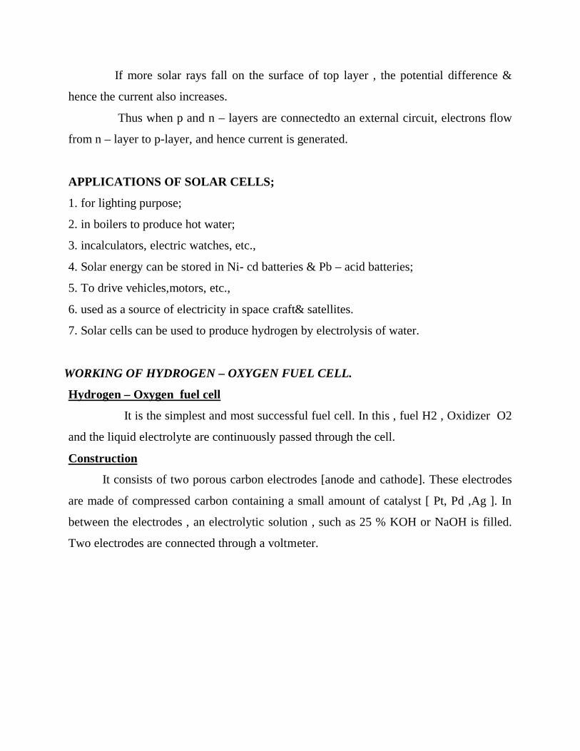
If more solar rays fall on the surface of top layer , the potential difference &
hence the current also increases.
Thus when p and n – layers are connectedto an external circuit, electrons flow
from n – layer to p-layer, and hence current is generated.
APPLICATIONS OF SOLAR CELLS;
1. for lighting purpose;
2. in boilers to produce hot water;
3. incalculators, electric watches, etc.,
4. Solar energy can be stored in Ni- cd batteries & Pb – acid batteries;
5. To drive vehicles,motors, etc.,
6. used as a source of electricity in space craft& satellites.
7. Solar cells can be used to produce hydrogen by electrolysis of water.
WORKING OF HYDROGEN – OXYGEN FUEL CELL.
Hydrogen – Oxygen fuel cell
It is the simplest and most successful fuel cell. In this , fuel H2 , Oxidizer O2
and the liquid electrolyte are continuously passed through the cell.
Construction
It consists of two porous carbon electrodes [anode and cathode]. These electrodes
are made of compressed carbon containing a small amount of catalyst [ Pt, Pd ,Ag ]. In
between the electrodes , an electrolytic solution , such as 25 % KOH or NaOH is filled.
Two electrodes are connected through a voltmeter.

LEAD – ACID STORAGE BATTERY.
It is a secondary battery which can act as a voltaic cell and as an electrolytic cell.
When it acts as a voltaic cell , it supplies electrical energy ; when it is recharged [ ie.,
current is sent in ] , the cell operates as an electrolytic cell.
Construction :
It consists of a number of [ 3 to 6 ] voltaic cells, connected in series to get 6
to 12 V battery . anode is made of Pb ; cathode is made of PbO2. A number of Pb &
PbO2 plates are connected in parallel separately ; the plates are separated from
adjacent ones by insulators rubber or glass fibre. The entire set up is immersed in dil.
H2SO4 having a density of 1.3 gm/ml. the cell is represented as :

From these reactions it is clear that PbSO4 is precipitated at both electrodes and
H2SO4 is used up. As a result , the concentration of H2SO4 decreases & hence the
density of H2SO4 falls below 1.2 gm/ml; so battery needs recharging.
Recharging:
it is done by sending current in the opposite direction. The electrode reactions get
reversed. As a result Pb is deposited on anode & PbO2 on cathode .
NI- CD BATTERY
This is also a rechargeable battery.
Description :
Nickel – Cadmium cell consists of a Cadmium anode and a metal grid containing a
paste of NiO2 acting as a cathode. The electrolyte is KOH
Cell is represented as : Cd ,Cd(OH)2 // KOH (aq) / NiO2,Ni
Working :
At anode :
Cadmium is oxidized to Cd2+ and further it combines with OH- to form Cd(OH)2

Cd + 2 OH- ------------------ Cd(OH)2 + 2e
At cathode :
NiO2 + 2 H2O + 2e ------------ Ni(OH)2 + 2 OH-
Net cell reaction :
Cd + NiO2 + 2 H2O + 2e ---------- Cd(OH)2 + Ni(OH)2 + energy
The products Cd(OH)2 and Ni(OH)2 adhere well to the surfaces of the corresponding
electrodes.
Recharging:
this is similar to lead storage battery. When the current is passed in the opposite
direction, the electrode reaction gets reversed. As a result Cd gets deposited on the
anode and NiO2 on the cathode.
LITHIUM BATTERY
Lithium battery is a solid state battery because instead of liquid or a paste electrolyte ,
solid electrolyte is used.
Construction ;
The lithium battery consists of a lithium anode and TiS2 cathode. A solid electrolyte ,
generally a polymer is packed between the electrolytes. The electrolyte (polymer)
permits the passage of ions but not that of electrons
Working (discharging)
When the anode is connected to cathode , lithium ions move from anode to cathode .
The anode is elemental lithium, which is the source of the lithium ions and electrons.
The cathode is a material capable of receiving the lithium ions and electrons.

Recharging the
Battery:
The lithium battery can be recharged by supplying an external current , which derives
the lithium ions back to the anode . the overall reaction is
Li Ti S2 Li + + TiS2–
This cell is rechargeable and produces a cell voltage of 3.0 V
**********************