
BC The STAR Detector Magnet Subsystem* · fabricated by Tesla Engineering, Ltd. of Storrington,...
5
1997 Particle Accelerator Conference The STAR Detector Magnet Subsystem* BNL-64461 e Vancouver, BC May 12-16, 1997 &0/$/=-97Q$03-- 89 R.L. Brown, A. Etkin, K.J. Foley, W.J. Leonhardt, J.A. Mills, I. Polk, E.S. Rodger Brookhaven National Laboratory, Upton, NY 11973 R.D. Schlueter Lawrence Berkeley Laboratory, Berkeley, CA 94720 Abstract The RHIC (Relativistic Heavy Ion Collider) Accelerator currently under construction at Brookhaven National Laboratory will have large detectors at two of its six intersection regions. One of these detectors, known as STAR (Solenoidal Tracker At RHIC), weighs 1100 tons and is being built around a large solenoid magnet. The magnet is 7.32 m in diameter, 7.25 m long and utilizes three different sizes of room temperature aluminum coils. The magnet will operate with a field set from 0.25 T to 0.5 T and have a field uniformity of better than 1000 ppm over a portion of its interior region. This paper describes the magnet design, fabrication and assembly requirements and presents the current construction status. Figure 1 1 INTRODUCTION The solenoidal Tracker At WIC (STAR) will search for signatures of quark-gluon plasma (QGP) formation and investigate the behavior of strongly interacting matter at high energy density. To accomplish this, a flexible detection system that can simultaneously measure many JUN2 4w experimental observables is being constructed. The system contains several subsystems such as the Time Projection Chamber (TPC), Silicon Vertex Tracker (SVT), Forward Time Projection Chamber (FI'PC) and the Electro-Magnetic Calorimeter @Me) as shown in Figure 1. These subsystems operate in a magnetic field generated by the Magnet subsystem (MAG) which is an iron dominated, conventional (room temperature) solenoid magnet. The field can be varied from 0.25 T to 0.5 T with a uniformity better than lo00 ppm over the entire TPC volume. 2 PHYSICS REQUIREMENTS & COMPUTER SIMULATION The momentum resolution requirements of STAR dictate that everywhere in the TPC volume The magnet must provide a uniform magnetic field over its operating range 0.25 < Bz < 0.50 T, while simultaneously minimizing radiation length to and providing structural support for the electro-magnetic calorimeter, provide a hole in the end poles at pseudorapidity q = 2.0 to allow particle transmission to external detectors, accommodate EMC fiber bundle routing to external electronics, and, most importantly, minimize STAR'S capital cost. A cross section of the quasi-&symmetric magnet is shown in Figure 2. The magnetic design achieves a 0.5 T field with uniformity characterized by: 3r I 2.3 mm and So I 1.0 mm over the entire TPC volume by using a combination of a Poletip Trim and Space Trim coils to appropriately compensate and straighten field lines. Radiation lengths to the EMC are minimized by positioning the coils radially outside the calorimeter, though at the expense of additional iron and conductor weight. The regularly spaced pancake coil design allows *This research was supported by the U.S. Department of Energy under Contract Nos. DE- ACO2-76CHO0016. r
Transcript of BC The STAR Detector Magnet Subsystem* · fabricated by Tesla Engineering, Ltd. of Storrington,...
1997 Part ic le Accelerator Conference
The STAR Detector Magnet Subsystem* BNL-64461 e Vancouver, BC
May 12-16, 1997 &0/$/=-97Q$03-- 89
R.L. Brown, A. Etkin, K.J. Foley, W.J. Leonhardt, J.A. Mills, I. Polk, E.S. Rodger Brookhaven National Laboratory, Upton, NY 11973
R.D. Schlueter Lawrence Berkeley Laboratory, Berkeley, CA 94720
Abstract
The RHIC (Relativistic Heavy Ion Collider) Accelerator currently under construction at Brookhaven National Laboratory will have large detectors at two of its six intersection regions. One of these detectors, known as STAR (Solenoidal Tracker At RHIC), weighs 1100 tons and is being built around a large solenoid magnet. The magnet is 7.32 m in diameter, 7.25 m long and utilizes three different sizes of room temperature aluminum coils. The magnet will operate with a field set from 0.25 T to 0.5 T and have a field uniformity of better than 1000 ppm over a portion of its interior region. This paper describes the magnet design, fabrication and assembly requirements and presents the current construction status.
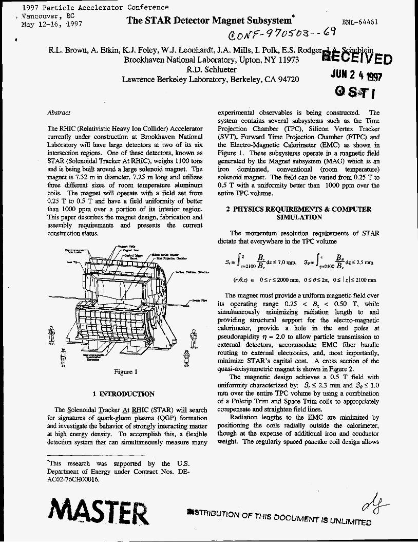
Figure 1
1 INTRODUCTION
The solenoidal Tracker At WIC (STAR) will search for signatures of quark-gluon plasma (QGP) formation and investigate the behavior of strongly interacting matter at high energy density. To accomplish this, a flexible detection system that can simultaneously measure many
JUN2 4w
experimental observables is being constructed. The system contains several subsystems such as the Time Projection Chamber (TPC), Silicon Vertex Tracker (SVT), Forward Time Projection Chamber (FI'PC) and the Electro-Magnetic Calorimeter @Me) as shown in Figure 1. These subsystems operate in a magnetic field generated by the Magnet subsystem (MAG) which is an iron dominated, conventional (room temperature) solenoid magnet. The field can be varied from 0.25 T to 0.5 T with a uniformity better than lo00 ppm over the entire TPC volume.
2 PHYSICS REQUIREMENTS & COMPUTER SIMULATION
The momentum resolution requirements of STAR dictate that everywhere in the TPC volume
The magnet must provide a uniform magnetic field over its operating range 0.25 < Bz < 0.50 T, while simultaneously minimizing radiation length to and providing structural support for the electro-magnetic calorimeter, provide a hole in the end poles at pseudorapidity q = 2.0 to allow particle transmission to external detectors, accommodate EMC fiber bundle routing to external electronics, and, most importantly, minimize STAR'S capital cost. A cross section of the quasi-&symmetric magnet is shown in Figure 2.
The magnetic design achieves a 0.5 T field with uniformity characterized by: 3r I 2.3 mm and So I 1.0 mm over the entire TPC volume by using a combination of a Poletip Trim and Space Trim coils to appropriately compensate and straighten field lines.
Radiation lengths to the EMC are minimized by positioning the coils radially outside the calorimeter, though at the expense of additional iron and conductor weight. The regularly spaced pancake coil design allows
*This research was supported by the U.S. Department of Energy under Contract Nos. DE- ACO2-76CHO0016.
r

for both calorimeter support to backlegs and EMC fiber bundle routes to external electronics. An end cap gap allows fiber bundle extraction through the ends. Flux density is B I 1.4 T everywhere at fuil coil energization, resulting in an excitation independent field uniformity.
1 OUTER END WNG I I
-POLETIP
I I
Figure 2 Magnet Quarter Section
Using poletip trim coils instead of shaping the poletip enables attainment of much better TPC field uniformity (3r I 1118x = 2.3 mm), well worth the additional coils and power supplies. The additional desirable feature of a flat machined poletip, with an unobtrusive trim coil recessed into the iron pole face, is incorporated into the design without impacting the attainable field uniformity.
Code calculations indicate that this robust design is capable of maintaining field uniformity even in the event of coil mispositionings by adjusting Poletip Trim and Space Trim coil settings. Current plans are to adapt the field mapping apparatus used to map the Aleph magnet at CERN. STAR and Aleph are similar in size and shape, therefore adapting the existing apparatus to the STAR geometry is not judged to require much effort.
3 MAGNET STEEL DESIGN
The Solenoidal Magnet steel is a cylindrical structure weighing 1,100 tons on axis with the collider beam and consisting of 30 flux return bars (backlegs), four end rings, two pole pieces, and support structures. The 6.85 m long flux return bars are trapezoidal in cross-section, and weigh 18 tons each. They form the outer cylinder wall encompassing the main and space trim excitation coils and are attached to an inner and outer end ring pair at each end of the magnet. The inner rings have a 5.27 m I.D. with thirty chord surfaces on the 6.28 m O.D. to control the azimuth location of each flux return bar, with an axial thickness of 285 mm, weighing 25 ton each. The outer rings are the structural connection between the ends of the flux return bars and the outer face of each inner ring and have the same I.D. as the inner rings with a 7.32 m O.D. and 203 mm axial thickness, weighing 35 ton each. Each pole piece weighs 73 ton and is on axis with, and supported by, the end rings and has a conical I.D. at q = 2 with a 525 mm axial thickness a 5.06 m O.D. and a
counter bore on the inner face for the pole tip trim excitation coil. A 107 mm annular gap exists between end ring I.D. and pole piece O.D. for utility routing to internal detector elements.
The main support structure consists of two cradles weighing 36 tons each supporting the lower nine flux return bars of the magnet cylindrical yoke. The main support structure is on Hillman Roller systems and hydraulic jacks and is supported and guided on two rails embedded into the floor, thus allowing the magnet to be moved via hydraulic jacks between experimental hall and assembly building as required. In addition to the main support structure there are two external pole piece support structures weighing 100 tons each that permit removal of the pole pieces for installation or maintenance of internal detector elements. All magnet yoke material was specified as AIS1 1008 killed steel that is vacuum degassed with a fully annealed heat treatment allowing for a minimum yield strength of 172 MPa; while the support structure material was specified as ASTM A36.
The magnetic field quality required that deflections in the magnet structure be minimized to less than 1 mm. This was accomplished with precise fabrication of magnet components and the use of high strength bolted and pinned connections between mating components. The prime contractor for fabricating the magnet steel was Precision Components Corp., York, PA., and materials for the magnet yoke were procured from Creusot-Marrel, France, for the flux return bars and end rings and Japan Steel Works, Japan, for the pole pieces. All components were provided as one piece forging except for the outer rings which were formed from four flame-cut arcs of flat rolled steel electroslag welded together to form each ring. Final fabrication of each component was performed either at PCC or their subcontractor Gec Alsthom, Cauada. End ring pairs were aligned and match pinned to insure accurate assembly and structural integrity. High strength threaded inserts were used in this low yield strength material along with Expansion Bolts, Torque Bolts, and Mechanical Tensioners from Superbolt Corp., Carnegie PA. The use of these high strength fasteners allowed us to achieve the fuced end bolted COM~X~~OIE needed to minimize deflection of the steel structure with accurate bolt tension using standard hand held torque wrenches. This also eliminated the need for anchor points in the steel to support much heavier mechanical or hydraulic torque wrenches used on standard hex-head fasteners.
4 COILDESIGN
The magnet contains three separate designs of coils each wound using aluminum conductor and insulated with fiberglass cloth vacuum impregnated with epoxy. Main and SDace Trim coils - These coils are built up from two layer pancakes wound two-in-hand (bifilar) fashion containing 13 turns. The pancakes are wound in both a "right-hand thread" and a "left-hand thread" manner and are assembled in an alternating thread manner to cancel out
c

undesired field components from the layer-to-layer winding transitions. The conductor used in the pancakes measures 53.9 rnm by 47.5 mm with a 16.8 mm diameter central water hole. Each pancake contains two parallel water circuits measuring approximately 120 m in length.
The magnet contains ten Main coils, each with four pancakes, and two Space Trim coils containing two pancakes each. These coils are all connected in series electrically, however all the water circuits (88) are in parallel. At the nominal 0.5 T magnet field, the current through these coils is 4744 amps with an additional 10% current through the Space Trim coils.
The nominal dimensions for these coils are as follows: 5.3 m I.D. by 6.0 m O.D. with an axial thickness of 0.45 m for the Main coils and 0.23 m for the Space Trim coils. Weights are approximately 6.8 tons for the main and 3.4 tons for the Space Trim coils. These coils have been fabricated by Tesla Engineering, Ltd. of Storrington, England. PoletiD Trim coils - Each poletip requires a trim coil to help preserve magnetic field uniformity. These coils contain six layers and are wound three-in-hand (trifilar) fashion giving 118 turns per coil. Each two layers contains three separate water circuits giving a total of nine circuits per coil. Water circuits are approximately 95 m long. The conductor measures 22.2 mm square with a 12.3 mm diameter central water hole.
Each coil is 1.8 m I.D. by 2.8 m O.D., has an axial thickness of 0.14 m and weighs about 1.2 tons. At the nominal 0.5 T magnet field, current through the Poletip coils will be 1441 amp. A vendor for these coils has not yet been chosen.
5 ASSEMBLY
The 6 o’clock experimental hall at RHIC has an Assembly Building (AB) in which the detector will be assembled and tested prior to rolling into the experimental hall. Assembly began with the installation of the base rails in a 1 m thick reinforced concrete floor running from the AB to the experimental hall. The two main support cradles were set atop the rails with one cradle being guided and the other as the follower. The lower nine flux return bars were installed, aligned, and welded to the main support cradles to form a monolithic support for the remaining magnet yoke and detector elements. Each end ring pair was then installed by first setting the inner ring in the cradle formed by the nine chord surfaces of each flux return bar. Then the outer ring was lifted and locked to the inner ring using taper pins and expansion bolts, and, to the ends of the lower nine flux return bars, using Torque Bolts. With end rings in place an additional six flux return bars were installed to mid-plane to form the lower half of the magnet yoke cylinder. The main and space trim excitation coils are then installed into the lower magnet yoke half s d g from each end ring and finishing at the axial mid-point of the magnet. When the coils have
been aligned and locked into place, the remaining fifteen upper flux return bars are installed to complete the assembly of the magnet core. The two pole pieces will be individually installed to complete the magnet assembly.
6 POWERSUPPLIES
There are 5 separate power supplies required for proper magnetic field shaping as shown in Figure 3. Due to the balanced nature of the power supply loads, ground potential on the main supply will be midway between the output terminal voltages. Power supplies (except for the booster) are separated into two parts, transformers, from NWL, Inc., Boardentown, NJ and rectifier control sections from Macroamp, Ukiah, CA.
7
palaup R.lm P0wa su ply 140 Tog
1800 unp
PaIeUp Trlm Power 8u ly
1800 .mp 140 -of?
Poleup 1wm coil e== y.in coil P.cLys 5% Qpaw Mm coil
Figure 3 STAR Electrical Connections.
7 CURRENTSTATUS
The magnet subsystem is 75% complete with the remainder to be completed in FY98. Both Main & Space Trim coil procurements are completed and the Pole Tip Trim coils are due for delivery the first quarter of FY98. All magnet steel fabrication is complete except fabrication of the pole tip supports and delivery to BNL, is planned for the second quarter of FY98. Delivery of the Power Supply System of transformers and rectifiers is expected in the first quarter of FY98.

DISCLAIMER
Portions of this dowment may be inegiible in electronic image products. Images are pduced from the best available original document.

DISCLAIMER
This report was prepared as an account of work sponsored by an agency of the United States Government. Neither the United States Government nor any agency thereof, nor any of their employees, makes any warranty, express or implied, or assumes any legal liability or responsibility for the accuracy. completeness, or use- fulness of any information, apparatus, product, or process disclosed, or represents that its use would not infringe privately owned rights. Reference herein to any spe- cific commercial product, proctss, or service by trade name, trademark, manufac- turer, or otherwise does not necessarily constitute or imply its endorsement, mom- mendation, or favoring by the United States Government or any agency thereof. 'The views and opinions of authors expressed herein do not necessarily state or reflect those of the United States Government or any agency thereof.