BC CARPENTER APPRENTICESHIP PROGRAM CARPENTER APPRENTICESHIP PROGRAM — LEVEL 1 11 ... while the...
52
BC CARPENTER APPRENTICESHIP PROGRAM LEVEL 1 Corrections JULY 2016
Transcript of BC CARPENTER APPRENTICESHIP PROGRAM CARPENTER APPRENTICESHIP PROGRAM — LEVEL 1 11 ... while the...

BC CARPENTER APPRENTICESHIP PROGRAM
LEVEL 1
CorrectionsJULY 2016


BC CARPENTER APPRENTICESHIP PROGRAM — LEVEL 1 11
Notes
LEARNING TASk 1 COMPETENCy A-3
WHMIS defines a controlled product as a pure substance or mixture that meets or exceeds criteria for inclusion in one or more of the WHMIS hazard classes. The hazard symbols shown in Figure 4 have been developed for each of those classes and divisions. The symbols must appear on the applicable supplier labels.
Information to Be Disclosed on an MSDSAll MSDSs must contain the following nine categories of information:
• Section 1: Product Identification and Use• Section 2: Hazardous Ingredients• Section 3: Physical Data• Section 4: Fire or Explosion Hazard• Section 5: Reactivity Data• Section 6: Toxicological Properties• Section 7: Preventive Measures• Section 8: First Aid Measures• Section 9: Preparation Date of MSDS
Section 1: Product Identification and UseThis section identifies the material by brand name, chemical name, or generic name, as well as other names by which the product is known. Identities of the manufacturer and supplier are also listed. The intended use of the product is also given.
Section 2: Hazardous IngredientsAll potentially hazardous ingredients of the material and the approximate amount (percent) of each ingredient of the material must be listed in this section. When a material contains ingredients that are registered as a trade secret, a registration number assigned by the Hazardous Materials Information Review Commission will appear in place of the ingredients. In the event of a medical emergency, the company must disclose the identity of the ingredients to a medical professional.
Section 3: Physical DataThis section describes the physical properties of a material.
Section 4: Fire and Explosion DataThis section describes the material’s fire and explosion capabilities and the procedures to follow in the event of a fire or explosion. It includes whether or not a material is flammable, and/or the conditions under which flammability should be a concern. The type of fire extinguishers to be used when the material is present will be stated, along with any special procedures that need to be followed during a fire. The flashpoint and method of ignition are stated.

Notes
12 BC CARPENTER APPRENTICESHIP PROGRAM — LEVEL 1
LEARNING TASk 1 COMPETENCy A-3
(Remember: the lower the flashpoint of the material, the greater the potential fire hazard.)
Section 5: Reactivity DataThis section gives the conditions under which the material will react, and what hazardous reactions will be created when it reacts. It also lists incompatible materials.
Section 6: Toxicological PropertiesThis section gives information on the health hazards relating to the material, including the route by which the material enters the body. Exposure limits are stated, along with the known effects of exposure.
Section 7: Preventive MeasuresThis section provides information on ways of controlling/preventing hazardous conditions. It lists the personal protective equipment that must be used when handling the material and the engineering controls that must be in place. The procedures to be followed in the event of a leak and/or spill, normal handling procedures and equipment, storage requirements, and shipping information are also given.
Section 8: First Aid MeasuresThis section describes the actions to be taken in case of overexposure to the material. The purpose of first aid is to minimize injury and future disability. In serious cases, first aid may be necessary to keep the victim alive. You need to be aware of this first aid information before you start working with the material. First aid procedures should be periodically reviewed, and everyone should know the location of the facilities and equipment for providing first aid (e.g., the eyewash unit and the first aid station).
Section 9: Preparation Date of MSDSThis section lists the MSDS author, date, and phone number. MSDSs must not be more than three years old. Note: If an MSDS sheet does not list the date it was prepared, it is not valid in Canada.

BC CARPENTER APPRENTICESHIP PROGRAM — LEVEL 1 31
Notes
LEARNING TASk 2 COMPETENCy A-3
See Competency A-2: Apply Personal Safety Practices for more information on respirators.
Airborne FibresParticles classed as airborne fibres are larger than particles in the “dust” class. Both dusts and fibres are carried in the air. Airborne fibres can be even more dangerous than the finest dusts. The composition of the fibres is the factor that determines the hazard—fibres from wood are irritants while asbestos fibres are linked to lung cancer.
ProtectionThe fibres from wood, fibreglass, and cellulose are primarily irritants—protect yourself with dust masks, gloves, and close-fitting clothing.
AsbestosAsbestos is a fibrous material used in many products (insulation, cement shingles, floor tiles) because it adds strength, heat-resistance, and chemical-resistance. During the past 20 years, exposure to asbestos is more common when old asbestos is removed or otherwise disturbed, rather than situations where new asbestos is installed. Workers repairing or renovating an old building may be at risk of exposure to asbestos used in the construction of that building.
Asbestos is a very hazardous material and requires extreme safety precautions. Its fibres are extremely fine and can stay in the air for hours—workers exposed to asbestos-contaminated air can inhale these fibres. If handled without caution, asbestos can cause serious chronic health problems.
Asbestosis is a chronic lung disease resulting from prolonged exposure to asbestos dust. The fibres gradually cause the lung to become scarred and stiff, making breathing difficult. Lung cancer may be caused by asbestos fibres in the lung.
Before beginning a construction project that may disturb asbestos-containing materials, company owners or principal contractors must file a Notice of Project - Asbestos (NOPA) form with WorkSafeBC.
For more information on working safely around asbestos, see the WorkSafeBC manual Safe Work Practices for Handling Asbestos, available at the website www.worksafebc.ca.

Notes
32 BC CARPENTER APPRENTICESHIP PROGRAM — LEVEL 1
LEARNING TASk 2 COMPETENCy A-3
Toxic MetalsThe term “heavy metals” generally refers to the toxic metallic elements:
• lead• mercury• arsenic• cadmium
These metals, or compounds containing these metals, tend to build up in the bodies of living organisms over a long period of time. Eventually the concentration of the metals reaches a point where they become toxic and pose a significant health hazard. These heavy metals can get into our bodies by inhaling contaminated dusts or by ingesting foods that have been exposed to or contain toxins.
LeadLead is a heavy metal occasionally found in old paint or plumbing solder. Sanding painted surfaces that contain lead produces airborne lead dust. Workers exposed to this dust risk inhaling it and may suffer from lead poisoning if proper safety precautions are not taken. Although lead has not been used in interior paints since the 1950s, refinishing lead painted wood is still a significant hazard.
Symptoms of lead poisoning include:
• digestive discomfort, constipation, anorexia, nausea• fatigue, weakness• personality change• headache• hearing loss• tremor, lack of coordination
MercuryMercury is a heavy metal that was used in switches, fluorescent light bulbs, and many other applications. In 1990, elevated levels of mercury were found in persons exposed to interior latex (water-based) paint containing phenylmercuric acetate, a preservative used to prolong the paint’s shelf life. In September 1991, phenylmercuric acetate was forbidden in the manufacture of interior or exterior latex paints.

BC CARPENTER APPRENTICESHIP PROGRAM — LEVEL 1 31
Notes
LEARNING TASk 3 COMPETENCy B-1
Scale RulesScale rules, sometimes called rulers or scale sticks, are made for all common metric and imperial scales. The imperial scale is known as the architectural scale.
Imperial scales read with different scales on the same face, one reading from left to right, and the other reading from right to left. The imperial scale also has a finely graduated scale at the beginning for accurate measurements of less than one foot.
2" -7" represented on the 3⁄16" scale (1⁄64 original size)
Figure 4 – 3/16" = 1'0" scale rule
Determining the Scale of a DrawingWhen working from construction drawings, it’s important to know the scale of the drawing. If unsure of the scale, derive it by comparing the actual size of a component to its dimensions on the drawing.
For example, consider the drawings shown in Figures 1 and 2 (where no actual scales are given). If you measure each drawing, you’ll see that Figure 1 is a little over 2 ¼" wide and approximately ¾" tall. Figure 2 is a little under 1 ½" wide and approximately ¾" tall.
To find the approximate horizontal scale of Figure 1, compare the measured width of the building (2 ¼") with the given width of the building (24'). Since 24' = 288", the approximate horizontal scale is 2 ¼ : 288 or 1:128.
Use the same method to determine the vertical scale, as well as both scales for Figure 2:
Approximate horizontal scale Approximate vertical scale
Figure 1 2 ¼" = 24' 0" (1:128) ¾" = 8' 0" (1:128)
Figure 2 (NTS) 1 ½" = 24' 0" (1:192) ¾" = 8' 0" (1:128)
(Note that since Figure 1 was drawn to scale, the horizontal and vertical scales are the same. However, since Figure 2 was not drawn to scale, the horizontal and vertical scales are different.)

Notes
32 BC CARPENTER APPRENTICESHIP PROGRAM — LEVEL 1
LEARNING TASk 3 COMPETENCy B-1
Scaling from DrawingsIf measurements are missing on construction drawings, you can find them by “scaling”. “Scaling” a measurement from a drawing means using a tape measure or scale ruler to measure the distance on the drawing and then applying the stated scale to calculate distance.
For example, if the distance from the outside corner of a building to the centre of a window is missing or appeared to be wrong, measure the distance and then apply the scale. If the distance measured is 1 ¼" and the scale is ¼" = 1'0" (1:48), then the centre of the window should be 5' from the outside corner of the building (1 ¼" × 48 = 60" = 5').
Scaling should be used only as a last resort because a scale drawing is distorted by reproduction and measurements obtained are often inaccurate. For example, if the distance measured in the above example is 1 5/16" (rather than 1 ¼"), the centre of the window would be placed at 5'3" from the centre of the building, a difference of 3"!
It’s best to calculate or call the architect for important missing dimensions and not to scale from the drawing unless absolutely necessary, and also be aware that the scaled dimension may not be accurate.
Now complete Self Test 3 and check your answers

BC CARPENTER APPRENTICESHIP PROGRAM — LEVEL 1 85
Notes
LEARNING TASk 9 COMPETENCy C-1
Wood Auger BitsAuger bits are used for drilling larger diameter, deeper holes in wood. They have a screw point design that ensures accurate cutting in hard and soft woods. The side spurs cut and define the edge of the hole, while the chisel-like cutting edge removes the waste within the previously cut circle. The threaded centre bites into the wood and pulls the bit into the timber.
Figure 4 – Wood auger bit
Ship Auger BitsShip auger bits are used for drilling in wood and for deep boring work in large timber. They’re used for installation of telephone and electrical wires and other similar uses that require drilling through studs and joists. The design is a single twist bit with wide fluting that clears the chips away quickly. The hex shank prevents slippage and the screw point tip allows quick penetration.
Never use a screw point bit in a drill press.
Figure 5 – Ship auger bit
Spade BitsSpade bits are general-purpose, inexpensive bits for high-speed rough boring of wood or plastics where a smooth finished hole is not critical. Spade bits are flat with a centring point and two cutters. They range in size from ¼ – 1½" in width and have a long shank. Extensions can be used to increase their reach. Spade bits are also known as speed bits and flat bits.
45º bevel
15º bevel
Cutter
Point
Figure 6 – Spade bit

Notes
86 BC CARPENTER APPRENTICESHIP PROGRAM — LEVEL 1
LEARNING TASk 9 COMPETENCy C-1
Forstner BitsForstner bits are used to bore smooth flat bottom holes, pocket holes, partial arcs, and end grain holes. These are best used in a drill stand because when used freehand, it’s difficult to control the positioning since there is no central pilot bit. They’re used for plywood, hardwood, and softwood.
Figure 7 – Forstner bit
Multispur BitA multispur bit is equipped with a brad point, a number of teeth at its perimeter, and one cutting lip to remove waste from the middle of the hole (Figure 9). The teeth at the perimeter cut the outside of the hole before the centre waste is removed. This leaves a hole with clean sides.
Multispur bits range in size from 25 to 75 mm (1–3"). These bits are most often used with a drilling jig for making the large hole required for door locks. When used with a drill press, the bits cut clean holes at an acute angle to the surface of the wood.
Figure 8 – Multispur bit

BC CARPENTER APPRENTICESHIP PROGRAM — LEVEL 1 65
Notes
LEARNING TASk 5 COMPETENCy C-2
Figure 14 – Latch and lock the clip
Coil Nailer OperationOperation is similar to the strip nailer.
Finish NailerFinish nailers drive 18-gauge finish nails up to 63 mm long (2 ½"). They’re used primarily in cabinet-making and inside finish carpentry.
Most finish nailers use strips that are interchangeable with other manufacturer’s equipment, providing you maintain the same gauge of nailers.
Figure 15 – Finish nailers - 18 gauge and 23 gauge

Notes
66 BC CARPENTER APPRENTICESHIP PROGRAM — LEVEL 1
LEARNING TASk 5 COMPETENCy C-2
Figure 16 – Selection of air driven nails
Finish Nailer LoadingDisconnect the nailer from the air supply before loading nails. Make sure the nailer is set for the length of nails you intend to use.
Strips of clean, rust-free, nails are loaded into the tool. The procedure is as follows:
1. Pull the follower back to the latch position (Figure 17).
2. Near the rear of the magazine, insert up to three strips of finish nails in the slot in the rail. As the nails slide forward, be sure their heads pass under the rail cover.
3. Release the follower by depressing the small button that locks it in place. Do not allow the follower to slam into the strips of nails.
Figure 17 – Loading a nailer

BC CARPENTER APPRENTICESHIP PROGRAM — LEVEL 1 35
Notes
LEARNING TASk 4 COMPETENCy D-1
Avoid using the instrument where there’s a lot of vibration, such as from soil compactors, pile drivers, etc. This could put the level out of alignment, thus requiring repairs.
The way in which an instrument is carried when mounted on its tripod is important (Figure 2). Leave the horizontal clamp loose so that the instrument can swing if it should accidentally hit anything. If there aren’t overhead obstacles, carry it over one shoulder with the instrument facing forward. If there are overhead obstacles (such as formwork shoring), carry the tripod under your arm with the instrument facing forward. If the route you must take is full of obstacles, and you must climb over walls or up and down ladders, transport the instrument in its case.
Figure 2 – Carrying the instrument
Never jar the instrument by banging it down at any time—treat the optical level as if it were a crate of eggs.
Never leave the instrument unattended. There are many ways an unattended instrument can be damaged on a busy construction site, such as being hit by a passing concrete truck or a swinging load on a crane. Some contractors paint the legs of the tripod in bright colours and attach streamers of bright surveyor’s tape as a precaution against accidents. Also, the instruments can be stolen if left unattended in a built-up area such as a busy downtown street.
Check all connections for the various parts of the tripod. Looseness at any connecting point can make it unstable and result in incorrect readings. The wood screw connections of wooden tripods are especially prone to loosening.
Now complete Self Test 4 and check your answers.
36 BC CARPENTER APPRENTICESHIP PROGRAM — LEVEL 1
LEARNING TASk 4 COMPETENCy D-1
Self Test 4
1. While an instrument is being transported from one job site to another, it should be:
a. left on the floor of the vehicle without a case
b. properly stored in its case
c. left for the job superintendent to look after
d. moved with just its protective lens caps
2. When an instrument is returned to its case:
a. It can go in any way.
b. The case should be left open always.
c. The lens caps need not be replaced.
d. It must be put back in the correct manner.
3. Tripods can be set up on any surface without any special precautions.
a. true
b. false
4. An optical level should be picked up by the:
a. telescope
b. focus knob
c. base
d. eyepiece
5. When securing an instrument to its tripod:
a. No special precautions are necessary.
b. The attaching screw should be seized up as tightly as possible.
c. Distractions are not important.
d. The attaching screw should not be overtightened.
6. If lenses become splattered with mud:
a. They can be wiped off with a cloth.
b. Cleaning should not start till the lens and the dirt are dry.
c. Cleaning should be done immediately.
d. Just wet it with water and dab the mud off with a camel hair brush.

BC CARPENTER APPRENTICESHIP PROGRAM — LEVEL 1 65
ANSwER kEy COMPETENCy D-1
Answer Key
Self Test 11. b. automatic level
2. c. self-levelling level
3. d. engineer’s level
4. c. measure angles both horizontally and vertically
5. d. more accurate
6. d. all of the above
Self Test 21. a. horizontal tangent dial
a. focussing dial
b. peep sight
c. eyepiece/Crosshair focussing dial
d. fish eye bubble
e. levelling knob
f. tripod mount
g. horizontal scale
2. by turning the eyepiece
3. by turning the focus knob
4. A tangent screw will not work unless the clamp is locked (just snug).
5. Leg thumbscrews are used to adjust the individual legs of the tripod.
6. Your sketches may vary.
Self Test 31. a. centimetres
2. c. read the scales in poor light
3. a. Plumb the rod
b. Can't see the rod
c. Rod up
d. Lower the rod
e. Move to the right
f. OK
66 BC CARPENTER APPRENTICESHIP PROGRAM — LEVEL 1
ANSwER kEy COMPETENCy D-1
Self Test 41. b. properly stored in its case
2. d. It must be put back in the correct manner.
3. b. false
4. c. base
5. d. The attaching screw should not be overtightened.
6. b. Cleaning should not start until the lens and the dirt are dry.
7. d. Damp-dry everything except the lenses and leave the case open until the instrument is completely dry.
8. a. true
9. d. can cause the interior lenses to fog up
10. a. true
11. d. place the instrument on your shoulder with the tripod legs pointing forward
12. a. true
13. a. true
Self Test 51. i. The instrument was not level to begin with.
ii. The instrument was accidently moved between sightings.
iii. The instrument was set up on unstable ground and some settlement or movement occurred.
2. i. Distance to the rod from the instrument was too great.
ii. The crosshairs were improperly focussed.
iii. A stadia line was read by mistake.
3. halfway between a benchmark and the location where the reading is to be taken
4. a. higher
5. i. not holding the rod plumb
ii. holding rod at the wrong location
iii. placing the rod on unstable ground
iv. having the rod turned around, inverted, or not properly extended

BC CARPENTER APPRENTICESHIP PROGRAM — LEVEL 1 63
Notes
LEARNING TASk 5 COMPETENCy G-3
BlockoutsVoids and recesses must often be created in concrete so that beams, pipes, or ductwork can be installed later. They’re easy to make and may be made of plywood, lumber, or rigid foam. Blockouts should be designed for easy stripping.
To make wood blockouts, construct a rigid box the same size and shape as the required recess. Nail the box to the inside of the form as in Figure 6, nailing from the outside so that the blockout will be left behind in the concrete when you strip the form.
Plywood topand bottomfront and back
Form
Air hole
Figure 6 – A simple blockout
The term “blockout” also applies to blocks of wood that are used to hold members such as steel beams precisely in position during concrete placement.
Levelling StripsIf the top of the form is above the height of the finished concrete, levelling (pour) strips are used to indicate the height at which workers should level the concrete. Typically a wooden strip such as a 19×38 mm (1×2) is used for this.
A B
19 × 38 mm
Chamfer stripsConcrete levelledto top of strips
Figure 7 – Two types of levelling strip

Notes
64 BC CARPENTER APPRENTICESHIP PROGRAM — LEVEL 1
LEARNING TASk 5 COMPETENCy G-3
The levelling strip may be a wooden chamfer or similar narrow piece of wood. The strip acts as a guide for floating and trowelling the concrete. It can also be used as an architectural feature. Strips can be on one or both sides of the wall.
A levelling strip will leave a notch in the top of the foundation wall, which will allow the wall sheathing to overlap the foundation. The exterior cladding can then overlap past the sheathing, creating a water-resistant joint where the framing meets the foundation (Figure 8).
Figure 8 – With levelling strip on left, without on right
BulkheadsA bulkhead is the end face of a section of formwork, acting as a vertical support to the concrete. Bulkheads are required at all places where the top of the foundation walls steps in height.
Most lumber bulkheads are made from 19 mm material nailed to a frame of 38 mm material. They can also be made from a solid piece of 38 mm thick lumber that’s ripped to fit. Wooden bulkheads are usually made 3 mm narrower than the thickness of the wall they serve.
If the bulkhead is used for forming a construction joint where two concrete members join, holes or notches are made in the bulkhead to allow passage of rebar, and the boards are nailed horizontally, at right angles to the frame. It’s easy to strip this type of bulkhead, since the boards can be split if necessary to free them from the concrete.

BC CARPENTER APPRENTICESHIP PROGRAM — LEVEL 1 87
Notes
LEARNING TASk 7 COMPETENCy G-3
slab volume = slab area × slab thickness = 359.16 m2 × 0.1 m = 35.92 m3
The total concrete required for the foundation is then:
footings 6.34 m3
walls 31.68 m3
slab 35.92 m3
total 73.94 m3
Sample Problem 2Use the plan and section drawing shown in Figure 2 to find the dimensions needed to calculate the volume of concrete for the foundation.
Section A - APlan view
900
150
300
300
3600
A
A
4000
0
8000
600024000
Figure 2 – Plan and section drawings for sample problem 2
Even though there is a jog in the corner of the building, the centreline perimeter is calculated the same way:
centerline perimeter = (40 m + 24 m) × 2 – (4 × 0.3 m) = 128.0 m – 1.2 m = 126.8 m
Notes
88 BC CARPENTER APPRENTICESHIP PROGRAM — LEVEL 1
LEARNING TASk 7 COMPETENCy G-3
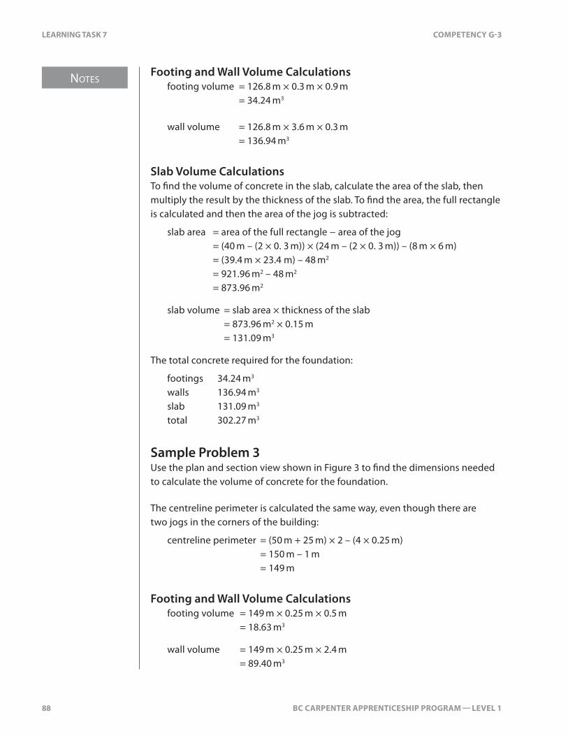
Footing and Wall Volume Calculations footing volume = 126.8 m × 0.3 m × 0.9 m = 34.24 m3
wall volume = 126.8 m × 3.6 m × 0.3 m = 136.94 m3
Slab Volume CalculationsTo find the volume of concrete in the slab, calculate the area of the slab, then multiply the result by the thickness of the slab. To find the area, the full rectangle is calculated and then the area of the jog is subtracted:
slab area = area of the full rectangle − area of the jog = (40 m – (2 × 0. 3 m)) × (24 m – (2 × 0. 3 m)) – (8 m × 6 m) = (39.4 m × 23.4 m) – 48 m2
= 921.96 m2 – 48 m2
= 873.96 m2
slab volume = slab area × thickness of the slab = 873.96 m2 × 0.15 m = 131.09 m3
The total concrete required for the foundation:
footings 34.24 m3
walls 136.94 m3
slab 131.09 m3
total 302.27 m3
Sample Problem 3Use the plan and section view shown in Figure 3 to find the dimensions needed to calculate the volume of concrete for the foundation.
The centreline perimeter is calculated the same way, even though there are two jogs in the corners of the building:
centreline perimeter = (50 m + 25 m) × 2 – (4 × 0.25 m) = 150 m – 1 m = 149 m
Footing and Wall Volume Calculations footing volume = 149 m × 0.25 m × 0.5 m = 18.63 m3
wall volume = 149 m × 0.25 m × 2.4 m = 89.40 m3
BC CARPENTER APPRENTICESHIP PROGRAM — LEVEL 1 41
Notes
LEARNING TASk 4 COMPETENCy H-1
LEARNING TASK 4
Describe the Terms Used in Platform-frame Construction
There are many terms used with platform-frame construction. This Learning Task describes terminology related to the structure of the building, the architectural design of the building, and the spaces created by framing.
Structural TermsThe foundation is the lowest part of the building on which the walls and floors rest. Foundations are typically concrete and consist of walls and footings. They support the structure and transfer the loads to the ground.
A manufactured beam or girder may have a camber or upward curve built into it. This prevents it from sagging due to its own weight or the load it must carry. These members may be made from glue-laminated wood products, steel, or concrete.
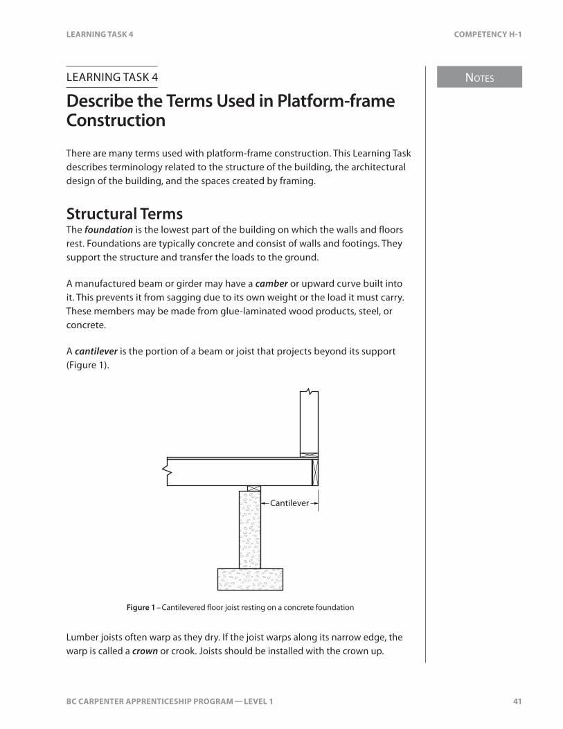
A cantilever is the portion of a beam or joist that projects beyond its support (Figure 1).
Cantilever
Figure 1 – Cantilevered floor joist resting on a concrete foundation
Lumber joists often warp as they dry. If the joist warps along its narrow edge, the warp is called a crown or crook. Joists should be installed with the crown up.

Notes
42 BC CARPENTER APPRENTICESHIP PROGRAM — LEVEL 1
LEARNING TASk 4 COMPETENCy H-1
Walls are used to support loads and define building spaces. Load-bearing walls carry loads such as floors or roofs. Non-load-bearing walls do not support any loads imposed on them. They may or may not be full-height walls.
• Partition walls define rooms and building spaces and may be load-bearing or non-load-bearing.
• Shear walls are used to provide lateral stability.
• Buttress walls are short walls built at right angles to the main wall. Usually longer at the bottom than at the top, they add extra support and stiffening to the wall (Figure 2).
Concrete buttress
Seepage cuto�
Base slab
River side Land side
Figure 2 – Buttress wall
Breaking joints is a term used to describe staggering the joints in sheathing or top plates. A distance of four feet usually offsets the end joints of plywood sheets. According to the Building Code, joints in top plates must be offset by at least one stud space, but good building practice dictates an offset of two or more stud spaces.
A uniformly distributed load means that the load along a structural member, such as a beam or a bearing wall, is consistent throughout the length of the beam or wall. Uniform loads are distributed evenly and do not require framing additional to the code prescribed spacing, materials, nailing patterns, etc.

BC CARPENTER APPRENTICESHIP PROGRAM — LEVEL 1 43
Notes
LEARNING TASk 4 COMPETENCy H-1
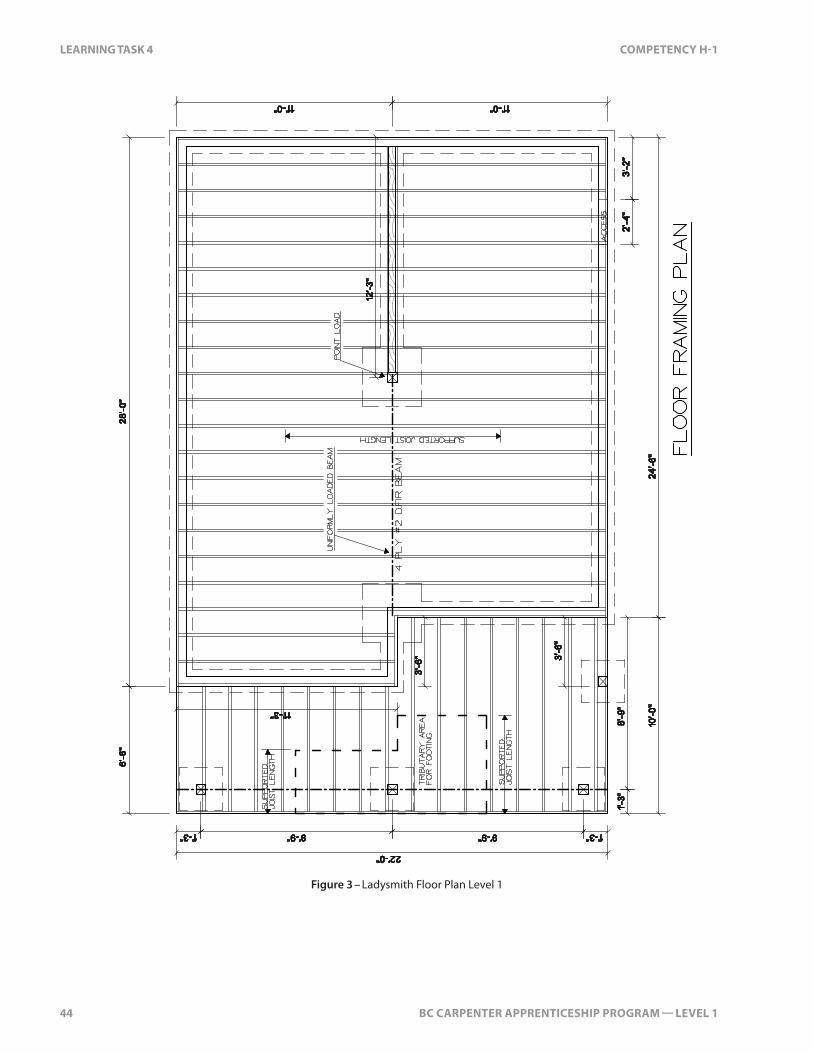
A point load is a concentrated load. For example, the bearing points that support a girder truss or beam are point loads. These points often required additional framing materials or hardware to protect wood from compression forces. For example, lintel with spans greater than 3 m require larger end bearing area. Engineers often require steel bearing plates under the bearing surfaces of girder trusses. Concentrated loads require a bearing path (load path) from top to foundation. Beam span tables within the building code may be used to size beams that have uniform loads but not for beams with concentrated loads.
Load path is the transfer of a load down to the foundation. This path is normally vertical. Where beams, lintels and cantilevers are involved the load path will move horizontally or at an angle. The bearing points of these members are a continuation of the load path to the foundation. Typically, building designers will align bearing walls or posts vertically for all floor levels throughout the structure.
Tributary width for beams and lintels is the supported joist length bearing on that member. For rafters, roof joists and trusses tributary width is the supported length which is usually half the span plus the projection.
Tributary area is the share of the structure that is being supported by a structural building component. Tributary area is used when calculating concentrated loads.
Figure 3 on the next page shows a point load on the post supporting the end of the 4 ply #2 DFir floor beam. A uniform load is along the beam itself.
The supported joist length (described in H-2 LT 2) in Figure 3 shows the tributary width of the floor bearing on the beam. It is the beam’s share of the load. From the mid-point of the joist the load goes half to the beam and half to the exterior wall.
The tributary area on the posts of the deck is the product of the tributary width (the supported joist length and cantilever) and half the span of the beam on both sides of the post.
44 BC CARPENTER APPRENTICESHIP PROGRAM — LEVEL 1
LEARNING TASk 4 COMPETENCy H-1
Figure 3 – Ladysmith Floor Plan Level 1

BC CARPENTER APPRENTICESHIP PROGRAM — LEVEL 1 83
Notes
LEARNING TASk 8 COMPETENCy H-1
Figure 9 – Effect of sap-stain and rot fungi on softwood cells
Rot fungi are the more serious of the two types. While sap-stain fungi can usually be controlled by thoroughly drying the wood, timber infected with rot fungi must be discarded or have the infected portions removed.
Rot fungi takes one of three forms:
• brown rot• white rot• dry rot
Brown RotBrown rot attacks the cellulose material that makes up the walls of wood cells. It eventually reduces the affected wood to a brittle, brownish material. Most types of brown rot do not persist after the wood has been dried.
White RotWhite rot attacks both the cellulose that makes up the cell walls and the lignin that binds the cells. White rot is also called “white speck,” which is an initial stage of white rot. Infection shows itself as a soft, pulpy mass of whitish material, which has no structural strength. Like most forms of brown rot, white rot develops before a tree is felled and does not persist after drying. It must be removed from finished lumber by sawing out infected portions.
Figure 10 – White rot

Notes
84 BC CARPENTER APPRENTICESHIP PROGRAM — LEVEL 1
LEARNING TASk 8 COMPETENCy H-1
Dry RotDry rot infects trees after they are felled and can continue to thrive after the lumber-drying process. Dry rot often turns up after wood is put into service and is expensive to remove. Despite the name, there is nothing dry about the places where this rot thrives. It appears in poorly ventilated areas such as cavities beneath wood floors. It also occurs in wood surfaces that are in contact with damp walls. The name “dry rot” comes from the condition to which infected wood is reduced: the wood breaks into dry brown cubes, which crumble to a fine dust under finger pressure.
Decay starts when all three of the following conditions are present:
• lack of ventilation• high moisture content• heat (warmth above 15°C)
When one of the above conditions is eliminated, decay is stopped—but nothing cures it. There are, however, measures that prevent decay:
• ensure that framing lumber has been dried to a moisture content of 19% or less
• ensure that wood placed in service is adequately ventilated
• protect wood from moisture sources
• treat wood to prevent fungus attack when located in high-moisture locations
Insect DamageAn infestation of insects can destroy the wood in a structure. Some insects that damage wood are:
• carpenter ant• western subterranean termite• Pacific dampwood termite• powder-post beetle• teredo worm• mountain pine beetle

BC CARPENTER APPRENTICESHIP PROGRAM — LEVEL 1 87
Notes
LEARNING TASk 8 COMPETENCy H-1
Male and female dampwood termites have brown bodies with long, translucent, brown wings. Their overall length is about 25 mm. The male and female usually leave the colony in large numbers during warm evenings in late summer. The worker termite is creamy white in colour and never leaves the wood in which it lives.
Control of the Pacific dampwood termite is usually a job for an experienced building contractor. All termite-damaged wood must be removed and all other repairs made, to ensure that all sources of moisture are eliminated. Spraying cannot solve this problem.
Powder-post BeetleThe powder-post beetle bores small round holes, 2–3 mm in diameter, throughout the wood. These are the exit holes of the adult beetle. Inside the wood are tunnels filled with fine sawdust and excrement. Fine powder may be observed coming out of the holes or in piles under the holes.
Figure 13 – Powder-post beetle damage
The adult beetle emerges from the wood between April and July. Eggs are laid in midsummer in cracks and holes in exposed wood. Grubs hatch from the eggs and enter the wood. Its feeding produces fine sawdust in the tunnels. One or more years after entry, the grub becomes an adult beetle.
The powder-post beetle commonly attacks structures under buildings. Sapwood with high moisture content in shaded areas is especially susceptible to attack. Structural damage to wood is caused by continual infestation of the wood. Serious weakening may occur even though the outside appearance is normal (other than the exit holes).
To control a powder-post beetle infestation, perform all work recommended by pest control management specialists. Ensure that all wood in the house is dry and, if necessary, treat it with an appropriate insecticide.

Notes
88 BC CARPENTER APPRENTICESHIP PROGRAM — LEVEL 1
LEARNING TASk 8 COMPETENCy H-1
Teredo WormThe Teredo worm is a destructive pest of submerged timber. Softwood can become riddled with tunnels within months of being in salt water.
Figure 14 – Teredo worm tunnel damage
Mountain Pine BeetleThe mountain pine beetle, is a species of bark beetle native to the forests of western North America from Mexico to central British Columbia. It has always been part of the ecosystem of the western forest, but several years of unusually hot, dry summers, mild winters and large areas of mature forest, have led to an epidemic.
In western North America, the outbreak of the mountain pine beetle peaked in 2005 and has destroyed wide areas of lodgepole pine forest, including millions of acres in British Columbia.
The beetle lays eggs under the bark and introduces blue stain fungus into the tree which blocks the flow of sap. The combination of the feeding larvae and the fungus girdles the tree and kills it in a couple of years. Once the tee dies, the beetles leave the tree. Blue stain is the tell-tale sign that the tree has been infected.
If the trees are harvested within 8–10 years of dying, the lumber is typically still sound. The wood will be dryer than normal and prone to checks and cracks. The blue stain does not affect the structural properties of the lumber

BC CARPENTER APPRENTICESHIP PROGRAM — LEVEL 1 101
Notes
LEARNING TASk 10 COMPETENCy H-1
LEARNING TASK 10
Select Panel Products and Engineered Products
Panel ProductsPanel-type products are made by binding and gluing wood particles, fibres, strands, wafers, veneers, and/or boards together to form engineered products. Many are used for sheathing walls, floors, and roofs. There are several basic types of panel products, including:
• plywood• oriented strand board (OSB)• waferboard• composition board
Reconstituted wood panel products are produced by processes involving pressure, adhesives, and binders. They may contain layers made from materials other than wood. Many of these sustainable products are made from waste wood and recycled materials. Common reconstituted wood panel products produced in Canada include OSB, waferboard, particle board, medium density fibreboard (MDF), hardboard, and cellulosic fibreboard (insulating board).
PlywoodPlywood is made from laminations of veneer. Softwood plywood is made from veneers that are peeled from a log. Hardwood plywood is made from veneers that are either peeled or sliced from a log.
Softwood PlywoodSoftwood plywood sheathing comes in 4 foot by 8 foot sheets (1.22 m × 2.44 m). The edges of the sheets are left square if used for wall or roof sheathing. Tongue and groove plywood (T&G) is used for floor sheathing (Figure 1).
Tongue Groove Figure 1 – Tongue and groove plywood

Notes
102 BC CARPENTER APPRENTICESHIP PROGRAM — LEVEL 1
LEARNING TASk 10 COMPETENCy H-1
Machining the tongue and the groove reduces the width of the sheet. A sheet of T&G plywood covers 47½". This reduction in width must be taken into account when calculating the amount of floor sheathing required.
Canadian manufactured unsanded exterior grade plywood is commonly available in the following thicknesses:
• 5/16"• 3/8"• ½"• 5/8"• ¾"
• 13/16"• 7/8"• 1"• 11/8" • 1¼"
Thicknesses for sanded plywood are about 1/16" (1.5 mm) less.
Plywood VeneerPlywood sheathing is made from softwood veneers. Logs used to make veneer are cut to just over 8 feet. The logs are turned on a lathe and full 8-foot-wide veneers are peeled off. The veneers are dried and graded.
Softwood plywood normally has 3, 5, 7, or 9 layers of veneer. The outside layers are called face layers and the inside layers make up the core. Sheets of plywood with fewer layers are weaker than sheets made of more layers.
The layers of veneer are laid at right angles to one another (cross-banded)—this strengthens the sheets. The two faces of the sheet have veneers with the grain parallel to the long dimension of the sheet.
The veneers are sprayed with waterproof resin glue and then pressed and heated. The pressure and heat quickly set the glue. After gluing, the sheets are trimmed square to exactly 4 feet by 8 feet.
For maximum strength, plywood sheathing should be installed with the length of the sheet (face grain) across its supports.
GradesPlywood is available in various grades and is either unsanded or sanded. A sample face grade stamp for unsanded plywood is shown in Figure 2.
Figure 2 – Unsanded plywood face grade stamp

BC CARPENTER APPRENTICESHIP PROGRAM — LEVEL 1 17
Notes
LEARNING TASk 2 COMPETENCy H-2
LEARNING TASK 2
Build Columns, Beams, and Pony Walls
Before the floor joists can be installed, their support must be in place. The columns support the beams, which in turn support the floor joists. Foundation walls are often stepped when constructed on sloping sites. Stepped foundations require pony walls to support the floor joists where the top of the foundation wall is shorter.
Columns A column is an upright member supporting a load. It’s also known as a “post,” and very short concrete columns are sometimes referred to as “piers”. Concrete columns are usually round, whereas wooden columns are usually rectangular.
Types and Sizes of ColumnsBoth wood and steel columns are used to support floors. The minimum nominal size of wood columns is 6×6, but they cannot be smaller in actual dimension than the width of the beam they are supporting. Steel columns must have a minimum diameter of 3 inches. The size of wood columns used to support carports may be reduced to 4×4 in nominal dimension. Round wood columns must not be smaller than 184 mm (7¼") diameter.
Wood ColumnsWood columns can be made from solid lumber or built up from 2×6s. Built-up columns are more common than solid lumber. Solid lumber columns are expensive and tend to twist and check as they dry.
Parallel strand lumber or glue-laminated lumber columns are often specified in engineered buildings. Engineers prefer these manufactured materials because their structural properties can be more carefully controlled.
Regardless of the type of wood column, the width of the column must fully support the beam. This will require column sizes greater than 6×6 for wide beams. It’s common to use a column made from 2×6s to support wide built-up beams.

Notes
18 BC CARPENTER APPRENTICESHIP PROGRAM — LEVEL 1
LEARNING TASk 2 COMPETENCy H-2
5-ply 2×10 post
5-ply 2×6 post
Figure 1 – Built-up 2×6 column
Steel ColumnsTubular steel columns are used to support floors. Most steel columns are adjustable to many different lengths and have a threaded head for fine adjustment. Adjustable steel columns can be used to correct settlement and shrinkage of framing members.
Length adjustment holeswith locking pin
4×7 ½" bearing plate with a threaded adjustment post
Figure 2 – Steel column supporting a 5-ply wood beam
BC CARPENTER APPRENTICESHIP PROGRAM — LEVEL 1 23
Notes
LEARNING TASk 2 COMPETENCy H-2
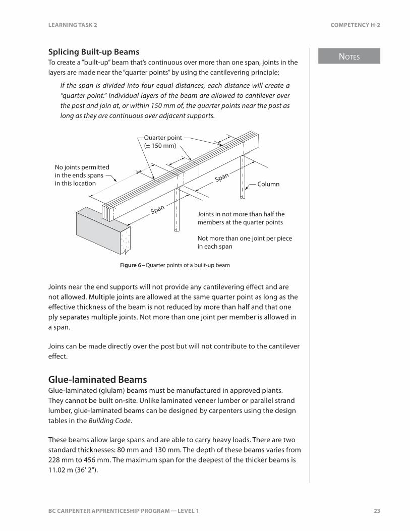
Splicing Built-up BeamsTo create a “built-up” beam that’s continuous over more than one span, joints in the layers are made near the “quarter points” by using the cantilevering principle:
If the span is divided into four equal distances, each distance will create a “quarter point.” Individual layers of the beam are allowed to cantilever over the post and join at, or within 150 mm of, the quarter points near the post as long as they are continuous over adjacent supports.
Span
Span
Joints in not more than half the members at the quarter points
Not more than one joint per piecein each span
No joints permittedin the ends spansin this location Column
Quarter point (± 150 mm)
Figure 6 – Quarter points of a built-up beam
Joints near the end supports will not provide any cantilevering effect and are not allowed. Multiple joints are allowed at the same quarter point as long as the effective thickness of the beam is not reduced by more than half and that one ply separates multiple joints. Not more than one joint per member is allowed in a span.
Joins can be made directly over the post but will not contribute to the cantilever effect.
Glue-laminated BeamsGlue-laminated (glulam) beams must be manufactured in approved plants. They cannot be built on-site. Unlike laminated veneer lumber or parallel strand lumber, glue-laminated beams can be designed by carpenters using the design tables in the Building Code.
These beams allow large spans and are able to carry heavy loads. There are two standard thicknesses: 80 mm and 130 mm. The depth of these beams varies from 228 mm to 456 mm. The maximum span for the deepest of the thicker beams is 11.02 m (36' 2").

Notes
24 BC CARPENTER APPRENTICESHIP PROGRAM — LEVEL 1
LEARNING TASk 2 COMPETENCy H-2
The minimum end bearing for glulam beams is 3½". If two beams are joined over one post, the width of the post must be 7" to support both beams adequately.
Steel BeamsWide flange steel beams can be used to support floors in wood-frame construction. Standard flange beams are not used in buildings because the narrow and sloped flange makes attaching wood joists difficult.
Web
Flange
Wide �ange beam Standard �ange beam
Figure 7 – Steel beams
Steel beams are manufactured to Canadian Standards Association (CSA) specifications. They come in various depths and weights. The depths vary from 150 mm to 310 mm.
W150 × 22W200 × 21W200 × 27W200 × 31
W250 × 24W250 × 33W250 × 39
W310 × 31W310 × 39
150 200 250 310
Figure 8 – Wide-flange steel beams
A beam designated as “W150 × 22” is 150 mm deep and weighs 22 kg per lineal metre. W200 beams are available in three different weights. The overall depth of the beam is the same for all three weights. The extra weight and strength of the heavier W200 beams comes from thickening the web and flange.
As with glue-laminated beams, carpenters can design steel beams using the design table in the Building Code.
BC CARPENTER APPRENTICESHIP PROGRAM — LEVEL 1 61
Notes
LEARNING TASk 3 COMPETENCy H-2
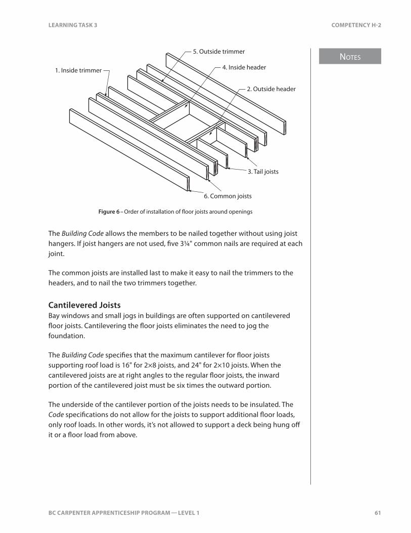
5. Outside trimmer
4. Inside header
6. Common joists
3. Tail joists
1. Inside trimmer
2. Outside header
Figure 6 – Order of installation of floor joists around openings
The Building Code allows the members to be nailed together without using joist hangers. If joist hangers are not used, five 3¼" common nails are required at each joint.
The common joists are installed last to make it easy to nail the trimmers to the headers, and to nail the two trimmers together.
Cantilevered JoistsBay windows and small jogs in buildings are often supported on cantilevered floor joists. Cantilevering the floor joists eliminates the need to jog the foundation.
The Building Code specifies that the maximum cantilever for floor joists supporting roof load is 16" for 2×8 joists, and 24" for 2×10 joists. When the cantilevered joists are at right angles to the regular floor joists, the inward portion of the cantilevered joist must be six times the outward portion.
The underside of the cantilever portion of the joists needs to be insulated. The Code specifications do not allow for the joists to support additional floor loads, only roof loads. In other words, it’s not allowed to support a deck being hung off it or a floor load from above.
Notes
62 BC CARPENTER APPRENTICESHIP PROGRAM — LEVEL 1
LEARNING TASk 3 COMPETENCy H-2
Engineered JoistsEngineered floor systems are not covered under Part 9 of the Building Code—an engineer must design them. The engineer uses Part 4 of the Building Code to design the floor system. Part 4 specifies maximum limits of movement for structural members within the system. When the phrase “must be designed in accordance to Part 4 of the Building Code” is used in the Code or on construction drawings, it means that a registered professional engineer must do the design.
An engineer may also be required to inspect the installation of these engineered products. A registered professional engineer must approve the installation of used or leftover engineered products.
Engineered joists are usually manufactured or fabricated in a plant. Documentation on how to store, handle, install, and brace the floor system products is supplied along with a layout by the manufacturer.
Engineered products must be handled with care. They must be kept dry and stored in a well-supported and level or plumb position. The installation of engineered joists and beams must be exactly as indicated on the drawings and connected as specified. A missing stiffener or simply installing a joist upside down can cause a structural failure.
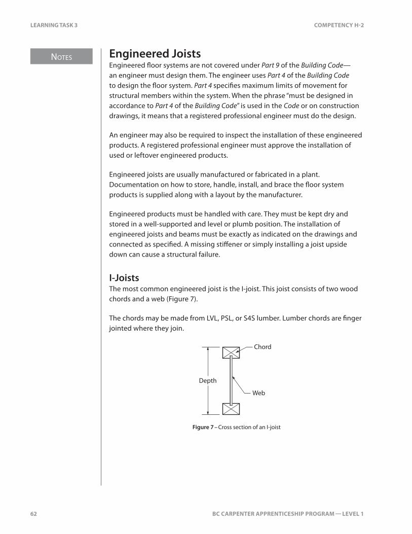
I-JoistsThe most common engineered joist is the I-joist. This joist consists of two wood chords and a web (Figure 7).
The chords may be made from LVL, PSL, or S4S lumber. Lumber chords are finger jointed where they join.
Chord
Depth
Web
Figure 7 – Cross section of an I-joist

BC CARPENTER APPRENTICESHIP PROGRAM — LEVEL 1 69
Notes
LEARNING TASk 4 COMPETENCy H-2
LEARNING TASK 4
Install Bridging
Bridging provides two types of support to the floor: it resists the twisting of the joists as they dry, and it distributes the load from one joist to adjacent joists. Twist restraint contributes to the rigidity of the floor system.
Types of BridgingThere are many types of bridging and with the exception of strapping, all use the rigidity of a triangular shape to support the joists.
Diagonal Cross-bridgingDiagonal cross-bridging (sometimes referred to as “herring bone” bridging) is the traditional form of bridging. It’s widely considered the best for distributing load from one joist to another. The minimum allowable size for diagonal cross-bridging is 1×3 or 2×2. These pieces of wood are fitted closely between the joists.
Solid blocking at7'0" maximum
Figure 1 – Diagonal cross-bridging
The top of adjacent pieces of bridging should meet at the top of the joist, as shown in Figure 1.

Notes
70 BC CARPENTER APPRENTICESHIP PROGRAM — LEVEL 1
LEARNING TASk 4 COMPETENCy H-2
Solid BlockingThe Building Code considers solid blocking equivalent to cross-bridging. Solid blocking utilizes left over scraps of floor joist material. The rows of the blocks are positioned no farther apart than 7'0" o.c.
Solid blockingat 7'0"
Figure 2 – Solid blocking
If fitted tightly, solid blocking can provide support equal to diagonal cross-bridging. The difficulty is fitting the blocking tightly. Solid blocking is usually offset by the thickness of the blocking to make it easy to end-nail. Care must be taken not to install the blocking too high or low. For this reason, the blocking is sometimes cut down in depth. Flat blocking at the bottom of the joists can be used for cavities containing ducting or large-diameter pipes.
StrappingStrapping consists of a 1×3 or larger board nailed no farther apart than 7'0" o.c. to the bottom of the joists. Strapping does not transfer floor load to the adjacent joists very well. Boards can be butted or lapped at joists, and the strapping course must continue to a sill at the boxing joist.
If the underside of the joists is covered with a panel-type ceiling finish made from gypsum, plywood, hardboard, fibreboard, particleboard, OSB, or waferboard, then the Building Code considers the joists to be the equivalent of strapped.
Layout of Diagonal Cross-bridgingDiagonal cross-bridging can be laid out in two ways: using a framing square or by using full-size joist layout.

BC CARPENTER APPRENTICESHIP PROGRAM — LEVEL 1 89
LEARNING TASk 6 COMPETENCy H-2
Self Test 6Use the Ladysmith Vacation Cabin plans to answer questions 1 to 11. Assume that the dimensions shown on the plans are to the outside of the sheathing.
1. The 1st floor is partially supported by a 4-ply #2 Douglas fir beam. What is the length of the clear span for this beam? (Assume the post is a full 6" × 6".) Convert your answer to metres.
2. What is the supported joist length for this beam? Convert your answer to metres.
3. Using the span tables in the BC Building Code Part 9, determine the minimum size of the beam.
4. Determine the clear span for the floor joists. Convert your answer to metres.
5. The floor joists are #2 S-P-F at 16" o.c. Using the span tables in the BC Building Code Part 9, determine the minimum size of the joists for the 1st floor. Assume only bridging is used.
6. How many pieces at what length are needed for the common joists? How many extra should be ordered for the boxing joists?

90 BC CARPENTER APPRENTICESHIP PROGRAM — LEVEL 1
LEARNING TASk 6 COMPETENCy H-2
7. From question #6, what is the total lineal footage needed and how many thousand board feet would that be?
8. Approximately how many pieces of 2×2 bridging are needed?
9. Calculate the number of 4' × 8' sheets of subflooring needed using both methods: the area method and counting the number of sheets.
10. Approximately how many screws are needed?
11. Approximately how many large tubes of adhesive are needed?

BC CARPENTER APPRENTICESHIP PROGRAM — LEVEL 1 99
ANSwER kEy COMPETENCy H-2
Answer Key
Self Test 11. high-rise construction
2. uplift created by wind forces and lateral forces caused by wind and seismic events
3. to support floor and/or wall framing, and to anchor the framing to the foundation
4. 2.4 m (8') o.c.
5. concrete consolidation and location
6. 1/8" larger than the bolt diameter
Self Test 21. because of its narrow and sloped flange
2. 5-ply 2×6 or a rough cut 8×8
3. 250 mm (10")
4. the point where the beam or joist leaves its support
5. because the point loads imposed on the footing are greater and need to be spread over a greater area
6. to support a column
7. Laminated Veneer Lumber, Parallel Strand Lumber
8. i. built-up wood
ii. steel
iii. glue-laminated
9. the quarter points of the clear spans closest to the interior supports
10. the amount of floor that a beam supports
11. Building width is the entire width of the building, and clear span is the distance between shear points.
12. downward deflection on one side of the support causes uplift on the other side of the support
13. 3.17 m
14. by having the posts for each beam line up over each other
15. it stretches the Building Code’s design to the maximum
100 BC CARPENTER APPRENTICESHIP PROGRAM — LEVEL 1
ANSwER kEy COMPETENCy H-2
16. A “flush beam” has the joists butting into it. For floors the beam is flush to the tops of the floor joists. In a ceiling the beam is flush to the underside of the ceiling joists.
17. i. load on the wall
ii. unsupported length of the studs
Self Test 31. friction between the fastener and the sub-flooring, due to lumber shrinkage
2. i. alignment of framing members
ii. economical use of material
iii. location of plumbing fixtures and plumbing walls
iv. location of bearing walls and non-bearing walls
v. location of floor openings
3. If the bearing wall is perpendicular to the joists, the supported wall must be directly over the supporting wall or offset by no more than 3' for ceiling loads and 2' for floor loads.
4. If the wall is parallel to the floor joists, place a joist directly under the wall to transfer the load to a bearing wall beneath.
5. If the non-bearing wall is parallel to the floor joists, support the wall with blocking between the joists at least every 1.2 m unless the wall lands on top of a regular joist.
6. Non-bearing walls perpendicular to the floor joists do not have to be blocked or supported by extra joists.
7. when the header joist exceeds 800 mm or 32" in length
8. 1½"
9. two 82 mm (3¼") toenails
10. no
11. centred in the space and 12" from the finished back wall
12. i. inside trimmers
ii. outside headers
iii. tail joists
iv. inside headers
v. outside trimmers
BC CARPENTER APPRENTICESHIP PROGRAM — LEVEL 1 23
LEARNING TASk 2 COMPETENCy H-5
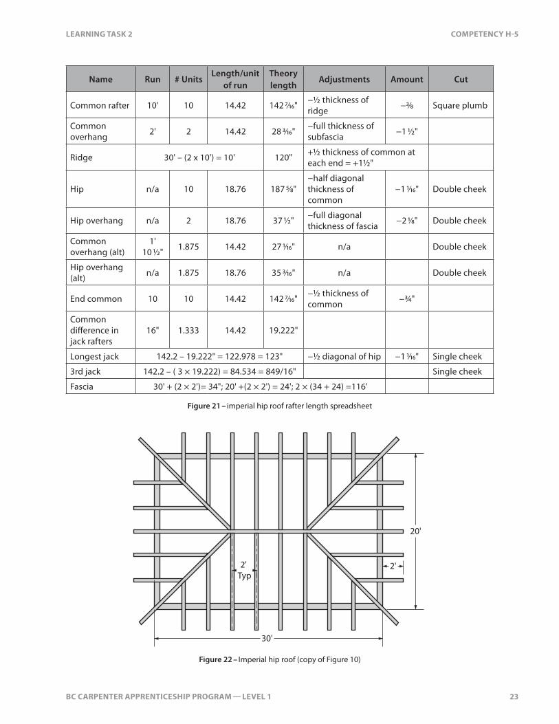
Name Run # UnitsLength/unit
of runTheory length
Adjustments Amount Cut
Common rafter 10' 10 14.42 142 7/16" −½ thickness of ridge −3/8 Square plumb
Common overhang 2' 2 14.42 28 3/16" −full thickness of
subfascia −1 ½"
Ridge 30' – (2 x 10') = 10' 120" +½ thickness of common at each end = +1½"
Hip n/a 10 18.76 187 5/8"−half diagonal thickness of common
−1 1/16" Double cheek
Hip overhang n/a 2 18.76 37 ½" −full diagonal thickness of fascia −2 1/8" Double cheek
Common overhang (alt)
1' 10 ½" 1.875 14.42 27 1/16" n/a Double cheek
Hip overhang (alt) n/a 1.875 18.76 35 3/16" n/a Double cheek
End common 10 10 14.42 142 7/16" −½ thickness of common −¾"
Common difference in jack rafters
16" 1.333 14.42 19.222"
Longest jack 142.2 – 19.222" = 122.978 = 123" −½ diagonal of hip −1 1/16" Single cheek
3rd jack 142.2 – ( 3 × 19.222) = 84.534 = 849/16" Single cheek
Fascia 30' + (2 × 2')= 34"; 20' +(2 × 2') = 24'; 2 × (34 + 24) =116'
Figure 21 – imperial hip roof rafter length spreadsheet
2' Typ
20'
30'
2'
Figure 22 – Imperial hip roof (copy of Figure 10)

Notes
24 BC CARPENTER APPRENTICESHIP PROGRAM — LEVEL 1
LEARNING TASk 2 COMPETENCy H-5
Calculation Example for a Metric Dimension Hip RoofUsing the example shown in Figure 22, for a 200 in 250 slope roof, built with SPF #1 lumber, in Kamloops, start by determining the size of the common rafter using the Building Code. With a span of 7.2 m, the run of the common rafter is 3.6 m. (Remember, the BCBC uses the term “span” for the run of the common.)
600 Typ
7200
10200
600
Figure 23 – Metric roof plan
Kamloops has snow load rating of 1.8, which is rounded to 2 for use in Span Table A-6 (Figure 23). Given the rafter spacing of 600 mm o.c., 38 × 184 commons and 38 × 235 hips can be used. A 19×235 ridge will be used.

BC CARPENTER APPRENTICESHIP PROGRAM — LEVEL 1 47
LEARNING TASk 6 COMPETENCy H-5
FasciaThe fascia extends all the way around the building: 34' + 34' + 24' + 24' = 116'. The hip ends require two 12-foot pieces each. The long sides require three 12-foot pieces each.
FastenersFasteners for sheathing include 2½" common nails, galvanized common nails, or staples. The Code minimum nailing pattern for sheathing is 150 mm o.c. along the edges and 300 mm o.c. on intermediate supports. Estimate an average of 35 per sheet. There are about 145 2½" common nails per pound.
Fastener estimates for dimension lumber are often estimated by the board foot of lumber in the building. For example, it takes about 20 pounds of 3½" nails for every 1000 board feet of roof framing lumber.
Each lineal foot of 2×6 is 1 board foot so, if 2×6s are used for the ceiling joists, stub joists, and common rafters, 920 board feet are required (288' + 88' + 544'). The hip rafters will be 2×8s (which have 1.333 board feet per lineal foot), so 80 × 1.333 = 107 board feet are needed. The total is 1027 board feet, so just over 20 pounds are needed for the roof framing.
It’s most common to purchase nails by the 50-pound box. Leftover nails move from job to job. There will be several deliveries or trips to the lumber yard during the construction and getting another box of nails is easy, as long as the carpenter anticipates the need and has the nails on site when required.
# of pieces Length Total Lumber order
Ceiling joists 24 12' 288' lineal 24 pcs @ 12'
Stub joists 22 4' 88' 11 pcs @ 8'
Ridge 1 12' 12' 1 piece @ 12' 1×8
Common rafters (including jacks and end commons)
34 16' 544' 34 pcs @ 16'
Hip rafters 4 20' 80' 4 pcs @ 20'
Sheathing 33 4' × 8' 981 sq feet 33 sheets
Fascia
2 × 12-foot per end
3 × 12-foot per length
116' 10 pcs @ 12'
Fasteners 35 per sheet of plywood 2½" 35 × 33 = 1155 145 per pound = 8
pounds
Fasteners Joists and rafters 3½" 20 lb./1000 bd ft. 20+ pounds
“H” clips 4 per sheet of plywood 4 × 33 = 132 132 “H” clips
Figure 2 – Spreadsheet for estimate of material

48 BC CARPENTER APPRENTICESHIP PROGRAM — LEVEL 1
LEARNING TASk 6 COMPETENCy H-5
600 Typ
7200
10200
600
Figure 3 – Plan view of metric hip roof
# of pieces Length Total Order
Ceiling joists10.2 - (2 × 1.2) = 7.8 m
7.8 ÷ 0.6 = 13 + 1= 14 per side × 2 = 28
7.2 m 202 m 28 × 12'
Stub joists 7.2 ÷ 0.6 = 12 + 1 per side = 13 × 2 = 26 1.2 m 32 m 13 × 8'
Ridge 1 3000 1 × 10'
Commons, end commons, and jacks
10.2 ÷ 0.6 = 17 + 1= 18 per side × 2 = 36 + 2 end commons = 38
5378 (line length +
overhang)205 m 38 × 18'
Hip rafters (including overhang) 4 6832 28 m 4 × 24'
Sheathing (11.4 × 8.4) × 320.156 / 250 = 122.6 sq.m.
2.438 × 1.219 = 2.972 sq.m. per 4' ×
8' sheet
122.6 ÷ 2.972 = 41.3 sheets
41.3 × 1.05 = 43.37 (round
up to 44 sheets)
Fascia 4 sides(11.4 × 2) + (8.4 × 2) =
39.6 m
Lengthwise: 4 × 14
Widthwise: 4 × 14
Figure 4 – Metric estimate of material
Now complete Self Test 6 and check your answers.

BC CARPENTER APPRENTICESHIP PROGRAM — LEVEL 1 11
Notes
LEARNING TASk 1 COMPETENCy H-6
Housed StringerHoused stringers are typically used in finished stairs. Special, adjustable templates are commercially available or a template can be made for the rise and run of the stair, which includes an allowance for wedges to tighten the treads and the risers in place. A router is used with the template to cut a gain (recess) into the side of the stringers. The treads and risers fit into the gains and are glued and wedged tightly in place.
Wedgefor tread
Base moulding
Housed stringer
Wedgefor riser
Figure 7 – Housed stringer
Semi-housed StringerA semi-housed or “planted” stringer has two parts: a cut-out stringer and a plain stringer. The plain stringer is a finished piece of wood attached to the wall. The cut-out stringer is laminated to the plain stringer. The treads and the risers butt into the finished plain stringer.
Plain stringer
Cutout stringernailed or screwed
to plain stringer
Figure 8 – Semi-housed or planted stringer

Notes
12 BC CARPENTER APPRENTICESHIP PROGRAM — LEVEL 1
LEARNING TASk 1 COMPETENCy H-6
Mitred StringerMitred stringers are used in finished stairs when one or both sides are open. They can be used in combination with a housed stringer on the wall side. Where the riser and stringer meet on the open side, the end of the riser is bevelled and the plumb cut on the stringer is mitred. The mitred join has no visible end grain.
Stringer
Moulding
Tread nosing return
Riser
Stringer
Nosing
Mitre nosingreturn
Figure 9 – Mitred stringer
The nosing of the tread returns on the outside edge of the facing stringer so that joints of balustrade and tread are covered.
Curved StringerCircular stairs can be built from wood, concrete, or steel.
Wooden stringers used in circular stairs are made of laminated layers of thin plywood.

BC CARPENTER APPRENTICESHIP PROGRAM — LEVEL 1 37
Notes
LEARNING TASk 3 COMPETENCy H-6
The finished stairwell opening (FSO) is the unknown and will be in the same proportion to the floor thickness + headroom as the run is to the rise.
Finished opening
Total run
Total rise
Floor thickness+
headroom
RunRise
Figure 2 – Stairwell opening triangles
The “floor thickness” is the sum of the ceiling finish, the joist depth, the subfloor thickness, and the finished floor thickness.
Metric Example No. of risers = 15 No. of treads = 14 Unit rise = 177 mm Unit run = 273 mm Headroom = 1950 mm Floor thickness = 227 mm
FSO
1950 227273177+
=
Finished Opening = 3358 mm Rough Opening = 3358 + 75 mm = 3433 mm
A common mistake when calculating the length of the rough opening is to forget to add the 75 mm allowance for nosing and finishes.
The resulting rough opening allowance is used to position the headers in the floor frame.

Notes
38 BC CARPENTER APPRENTICESHIP PROGRAM — LEVEL 1
LEARNING TASk 3 COMPETENCy H-6
The following formula is a shortened version of the similar triangle equation above with the 75 mm allowance added:
Rough opening =
Unit runUnit rise
(Headroom + F× lloor thickness) + 75mm
Imperial Example Total Rise = 107 ¼" Desired rise = 7"
107.25" ÷ 7" = 15.32 rises (round down to 15 rises) 107.25" ÷ 15 = 7.15" = 7 1/8"
Trying all three proportion rules, we find that all runs are Code-compliant:
• rise + run = 17": 17" – 7.15" = 9.85"
• (2 × rise) + run = 24" 24" – 14.3" = 9.7"
• rise × run = 72" 72" ÷ 7.15" = 10.07"
Given a floor thickness of 11¼" and desired headroom of 6' 6":
FSO89 25
9 857 15. ". ". "
=
Finished stairwell opening = 122.953" Rough stairwell opening = 122.953" + 3" = 125 15/16" (frame it at 126")
Unit of BridgeThe hypotenuse of the rise and run triangle is referred to as the “unit of bridge.” The unit of bridge is useful when laying out long stair stringers and calculating the stringer length and will be discussed in greater detail in Learning Tasks 4 and 5 of this Competency.
BC CARPENTER APPRENTICESHIP PROGRAM — LEVEL 1 53
Notes
LEARNING TASk 4 COMPETENCy H-6
Handrails must be attached directly to framing members. It’s best to install solid blocking between the studs along the stairs at the height where the handrail brackets are attached. Brackets cannot be greater than 1.2 m apart.
HeightThe height of handrails must be between 865 and 965 mm above the nosing line. Guards are set at 1070 mm above the landing surface. (Within a dwelling unit, guards can be 900 mm above the landing surface.) Refer to the Building Code for further information.
GraspableThe handrail must be continually graspable. The user must be able to grip the rail without having to stretch their hand. This means that 2×4s or 2×6s on flat are not allowed.
Now complete Self Test 4 and check your answers.

54 BC CARPENTER APPRENTICESHIP PROGRAM — LEVEL 1
LEARNING TASk 4 COMPETENCy H-6
Self Test 4
1. Sketch the layout of the top end and the bottom end of a stair stringer with the following specifications:
Unit rise = 172 mm Unit run = 258 mm Stringer size = 2×10 Subfloor = ¾" plywood Finish floor = 25 mm ceramic tile at the bottom and 5/8" hardwood at the top Riser board = ¾" plywood Tread = 1½" lumber
Show all parts with their dimensions.


![Chisel Bootcamp · If your system is set up correctly, you should see a messsage [success] ... chisel.eecs.berkeley.edu/chisel-bootcamp.pdf. Chisel 8 A hardware ... valy…](https://static.fdocuments.us/doc/165x107/5ac440717f8b9a12608ce0d3/chisel-bootcamp-your-system-is-set-up-correctly-you-should-see-a-messsage-success.jpg)


![UCB CS294-88: Declarative Design [0.2cm] Chisel Overviewinst.eecs.berkeley.edu/~cs294-88/sp13/lectures/chisel-review.pdf · UCB CS294-88: Declarative Design Chisel Overview Jonathan](https://static.fdocuments.us/doc/165x107/60417694dde8db15be43b6a8/ucb-cs294-88-declarative-design-02cm-chisel-cs294-88sp13lectureschisel-reviewpdf.jpg)


![Getting Started with Chisel - University of California ...cs250/sp16/handouts/chisel-getting... · Getting Started with Chisel Jonathan Bachrach, ... you should see a messsage [success]](https://static.fdocuments.us/doc/165x107/5ac440717f8b9a12608ce0dc/getting-started-with-chisel-university-of-california-cs250sp16handoutschisel-gettinggetting.jpg)