BC 1/29/15 GSB 01/28/15 x - Marion...
25
x BC 1/29/15
Transcript of BC 1/29/15 GSB 01/28/15 x - Marion...

x
BC 1/29/15
tanesha
Typewritten Text
GSB 01/28/15
tanesha
Typewritten Text
x

Company Submittal Data
Project
Marion County (ORCPP) Jail Work Release Center
HVAC Replacement
3950 Aumsville Highway SE
Salem, OR
Presented To
SOLARC Engineering and Energy + Architectural Consulting 319 SW Washington, Ste. 311
Portland, OR 97201
Presented By
Precision Test & Balance, Inc. P.O. Box 23186
Tigard, Oregon 97281
Table of Contents
Section A: Letter of Introduction
Section B: Principle & Key Staff
Section C: Qualifications of Key Personnel
Section D: Scope of Services & Project Approach
Section E: Experience with Mechanical Systems & Equipment
Section F: Experience with Mechanical Controls Systems
Section G: Project Management History
Section H: Reference List
Section I: Instrument Calibration Report
Section J: Forms

Section A Letter of Introduction
Precision Test & Balance, Inc. was established in 1999 to provide our clients with
maximum service at an affordable price.
Our corporate philosophy is to work closely with owners, design engineers and
contractors to achieve optimum performance of mechanical systems.
As a service company our only product is a report, however, a well designed and
balanced HVAC system can be recognized by the lack of occupant comfort complaints.
We believe that a gradual and controlled growth policy will ensure our balancing
technicians have been trained thoroughly according to NEBB and AABC standards.
The principles of Precision Test & Balance, Inc. have over fifty years of
combined experience, which will be covered in other sections, but we think it is
important to mention that we have worked on many projects involving educational,
commercial, industrial, medical research and hi-tech facilities.
We look forward to working with you in the near future.
Sincerely,
Douglas L. Forster Richard D. Forster
President Vice President

Section B Principles & Key Staff Members
Principles
Douglas L. Forster, President
Richard D. Forster, Vice President
Staff
Joseph Myott, Project Manager
Adam Jakobsen, Technician
Rich Martin, Technician
Amy Porter, Office Manager

Section C Qualifications of Key Personnel
Douglas L. Forster
Associate Degree Mechanical Engineering Technology
NEBB Supervisor Air Systems Testing and Balancing
NEBB Supervisor Hydronic Systems Testing and Balancing
EIT Certificate #60122
19 Years of Field Experience Testing and Balancing with Northwest
Engineering Service, Inc.
15 Years Principle – Precision Test & Balance, Inc.
Richard D. Forster
8 Years of Field Experience Testing and Balancing with Northwest
Engineering Service, Inc.
15 Years Principle – Precision Test & Balance, Inc.
Rich Martin
BA Business Administration University of Oregon
7 Years Precision Test & Balance, Inc.
Joseph Myott
Associate of Applied Science Degree in HVAC/R
EPA universal certified.
Five years HVAC/R experience in various areas.
4 years with Precision Test & Balance, Inc.
Adam Jakobsen 3 years with Precision Test & Balance, Inc.

Section D Scope of Services & Project Approach
A. Scope of Services
We at Precision Test & Balance, Inc. feel we offer a full range of services in
the HVAC testing, adjusting and balancing field. Our services include:
1. HVAC Air Systems Testing, Adjusting & Balancing
2. HVAC Hydronic Systems Testing, Adjusting & Balancing
3. HVAC Systems Monitoring & Surveying
4. Lab Hood Certification
5. Cleanroom Certification Testing
6. Sound & Vibration Testing
B. Project Approach
Following is a brief outline of approaching a project.
1. Initial Planning
A. Review Plans and Specifications
B. Assess Design Intent
2. Initial Review
A. Plan and schedule Testing, Adjusting and Balancing procedures
B. Set-up project on appropriate test forms
C. Preliminary field check of HVAC equipment and systems
D. Collect equipment data verify with design
E. Report any deficiencies that would prevent system to be properly
balanced

Cont. Section D
3. Data Procurement
A. Acquire fan and pump curve submittal data
B. Acquire any manufacturers published data, i.e., electrical, air, water or
control elements
4. System Field Review
A. Locate all balancing or control devices
B. Report any deficiencies in installation
C. Verify systems readiness for balancing, i.e., automatic controls
5. System Start-up
A. Verify piping and ductwork are clear of obstructions
B. Bump fans and pumps for proper rotation
C. Assist Mechanical Contractor with system start-up
6. Air Balance Procedure
A. Set fan condition for full-flow (cooling)
B. Check motor amperage
C. Traverse fan total for design volume
D. Change fan speed if necessary
E. Spot check for air circulation in various rooms
F. Balance supply system (proportional method)
G. Balance return or exhaust systems (proportional method)
H. Re-adjust supply and return fans speeds as needed
I. Read out systems for final readings

J. Record fan(s) operating data under required conditions
7. Hydronic Balance Procedure
A. Set pump condition for full flow (heating or cooling)
B. Measure amperage
C. Measure pump total and adjust if necessary
D. Spot check for water circulation at various coils
E. Balance water system (proportional method)
F. Re-adjust pump volume for 100% flow if possible
G. Read out water system
H. Record pump(s) operating data under required conditions
8. Reporting
A. Review field data
B. Report any discrepancies encountered during the project
C. Input all data into a computer for future reference
D. Edit reports for typographical errors or omissions
E. Duplicate for distribution all applicable data and blueprints with
elements or openings numbered for easy reference
F. Publish required number of reports for review

Section E Experience with Mechanical Systems & Equipment
Following is partial list of mechanical systems and equipment we have worked on and
have extensive experience with.
1. Fan Systems 2. Terminal Units 3. Water Systems
Package Variable Volume Pumps (Primary)
Built-up VAV with Reheat Pumps (Secondary)
VAV Constant Volume Pumps (Tertiary)
Constant Volume CV with Reheat Chillers
Dual Duct Dual Duct Boilers
Multi-zones Fan Powered Parallel Steam
Process Exhaust Fan Powered Series Cooling Towers
Utility Exhaust Induction Water Cooled Units
Split Systems Pressure Dependent
Makeup Air Pressure Independent

Section F Experience with Mechanical Control Systems
We have working knowledge of the following control systems.
1. Powers, Landis & Gyr, Siemens
2. Johnson
3. Honeywell
4. Barber-Coleman
5. Robert Shaw
6. Staefa
7. Trane Tracer
8. Trane Intellipak
9. Carrier Parker Valve
10. Phoenix Valves
11. Metasys
12. Allerton
13. Delta
We have an excellent working relationship with all of the major control companies and
often on a first name basis with most control fitters and technicians.

Section G
Project Management History (Partial)
Projects Managed by Richard “Duke” Forster
Projects Contacts
US Bancorp Tower & Plaza Buildings Mr. Darrel Shereck
Construction & Sustaining Unico Properties
Portland, Oregon
Merix Corporation Mr. Jack White
Construction, Sustaining, Certifications Engineer
Forest Grove, Oregon
Lakeridge High School Mr. Chuck Foreman
Construction & Remodels Total Mechanical, Inc
Tektronics, Building 63 Mr. Bob Davis
New Construction Siemens
Portland, Oregon
Shinitzu Mr. Bill Dewsnap
New Construction, Certification Hoffman Construction
Tualatin, Oregon
Providence St. Vincent Hospital Mr. Matt Masters, P.E
Construction, Sustaining PSVMC Facilities
Portland, Oregon
St. Charles Medical Center Mr. Kevin Link
Bend, OR Skanska USA PM
Fred Meyer Stores Northwest & Alaska Mr. Wael Chamsedine
56 Projects Oregon, Washington, Alaska, Idaho Owner Wytek Controls

Projects Managed by Douglas L. Forster
Projects Contacts
ETEC Systems, Inc Cary Vincent
New Construction Facilities Manager
Mitsubishi Silicon America Steve Frank
New Construction, Sustaining, Certifications Operations Lead
Maxim Integrated Circuits Drew Wilder
Sustaining Corbin Engineers
Oregon Regional Primate Center Animal Svcs Building Collin Weber
New Construction, Certifications Facilities
Meridian Park Hospital ICU Exp. Bob Byers
New Construction Facilities Manager
Tualatin, Oregon
Siltec Silicon Epitaxial Building Steve Smith
New Construction, Sustaining Operations Lead
Salem, Oregon
Tuality Community Hospital Hank Foster
New Construction Facilities Manager
Hillsboro, Oregon
Wacker Siltronic Brett Edwardsen
Construction Facilities Engineer
Portland, Oregon
Portland International Airport Linda Simmes
New Construction, Sustaining Port Of Portland
Portland, Oregon
Toshiba Ben Adao
Construction, Certifications Shimizu America
Hillsboro, Oregon
Triquint Semiconductor Dennis Boom
Certification Engineering Manager
Hillsboro, Oregon

Providence St. Vincent’s Hospital John Casessa, PE.
New/Sustaining Projects Mgr. Physical Plant
Portland, OR
North Clackamas School District Mr. Dave Church
Clackamas, OR Facilities Director
Wallowa Memorial Hospital Mr. Jason Oak
New Construction Skanska USA
Enterprise, OR. Project Manager
Section H Reference List
1. Steve Strauss, P.E. Glumac International Portland, OR 503/227-5280
2. Byron Ramos, P.E. I.D.C. Corvallis, OR 541/752-8932
3. James Thomas, P.E. Glumac International Portland, OR 503/227-5280
4. Ed Carlyle, P.E. R & W Engineering Portland, OR 503/292-6000
5. Creighton Kearns, PE Interface Engineering Portland, OR 503/274-0908
6. Temple Looney P.E. Merix Corporation Forest Grove, OR 503/359-9300
7. Scott Landrigan Encompass Materials Group Vancouver, WA 360/254-0221
8. Paul DuPont P.E. Interface Engineering Portland, OR

Section I Instrument Calibration List
INSTRUMENT / SERIAL# APPLICATION DATE OF
USE
CAL. TEST
DATE
Shortridge AMD-860C / M14381 Air Balance TBD 07/28/2014
Davis A2/-4” / 87489B Air Balance TBD 12/13/2014
Milwaukee 2237-20 / B87A911121371 Electrical TBD 08/13/2014
Shortridge HDM-250 / W14119 Water Balance TBD 11/04/2014
Tegam 819A / T-300549 Temperature TBD 11/19/2014
Fisher Scientific 02-401-1 /
122212966 Rotation
Measurement TBD 11/19/2014
Extreme Performance DLT5-600 /
194036 Duct Leakage TBD 05/06/2014
Instruments Listed are those typically used on projects. Some instruments
may not be used on all projects. Instruments may be calibrated again prior to
project depending on timeframe.

Section J Balancing Forms (Partial)
1. Fan Data Sheet
2. Airflow Data Sheet
3. Small Fan Data Sheet (<1/6HP)
4. Minimum Outside Air by Temperature
5. Pump Data Sheet
6. Water Flow Data Sheet (Fixed Restriction)
7. Water Flow Data Sheet (Regulating Device)
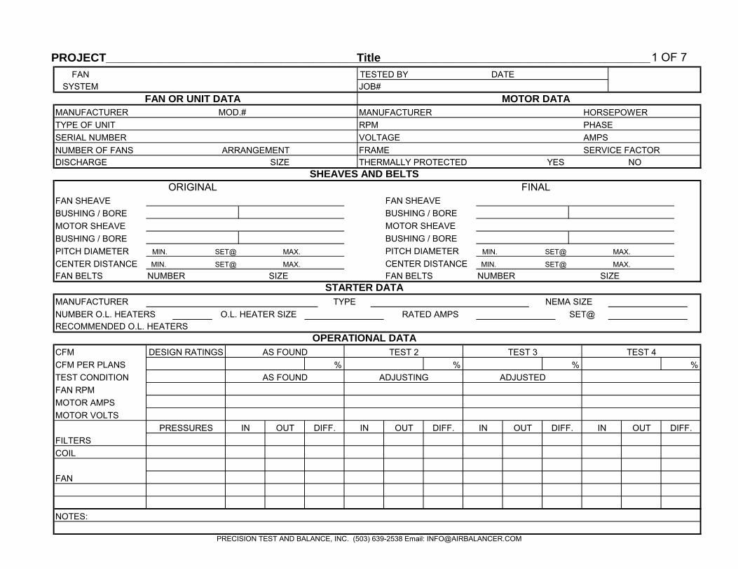
PROJECT____________________________________________________________________________________ Title 1 OF 7
FAN OR UNIT DATA MOTOR DATA
MANUFACTURER HORSEPOWER
NUMBER OF FANS ARRANGEMENTDISCHARGE SIZE
SHEAVES AND BELTS
ORIGINAL FINALFAN SHEAVEBUSHING / BOREMOTOR SHEAVEBUSHING / BOREPITCH DIAMETERCENTER DISTANCEFAN BELTS
STARTER DATA
OPERATIONAL DATA
% % % %
NOTES:
MOTOR VOLTSMOTOR AMPSFAN RPMTEST CONDITION
CFM
NUMBER
DESIGN RATINGS AS FOUND
MIN. MAX.
NUMBER O.L. HEATERSMANUFACTURER
O.L. HEATER SIZE
FAN SHEAVE
SIZE
MOTOR SHEAVEBUSHING / BORE
FANSYSTEM
MANUFACTURER
SERIAL NUMBERTYPE OF UNIT
MOD.#
TESTED BY DATEJOB#
VOLTAGEFRAME
PHASERPMAMPS
OUTIN OUT
TEST 2 TEST 3
NUMBER
DIFF.
MAX.
DIFF.DIFF. IN
SET@MIN.
PITCH DIAMETER
SET@RATED AMPS
AS FOUND
BUSHING / BORESET@MIN.
TYPE
FAN BELTSCENTER DISTANCE
MAX.
OUT DIFF.
NEMA SIZE
RECOMMENDED O.L. HEATERS
CFM PER PLANS
SIZE
INOUT
TEST 4
MAX.
PRESSURES IN
ADJUSTEDADJUSTING
FAN
COIL FILTERS
SET@
SET@
SERVICE FACTORYES NOTHERMALLY PROTECTED
MIN.
PRECISION TEST AND BALANCE, INC. (503) 639-2538 Email: [email protected]

PROJECT__________________________________________________________________________________
___Title 2 OF 7
RF
RF 1 = FLOW HOOD, 2 = ROTATING VANE ANEMOMETER, 3 = PITOT TUBE TRAVERSE, 4 = VELGRID, 5 = AIRFOIL
TEST CONDITION
SIZE
JOB #
AS FOUND ADJUSTING ADJUSTED
TEST 4
%CFMFPM
SYSTEM
GRILLE ORDIFFUSER DATA
FAN
LOCATION OWNERS
OPENING#
DATAEQP. NAME
TESTED BY
AREA K
FAN RPM
FPM CFM
DESIGNED
DATE
ROOM#
TEST 3
%CFM%
NOTES:
AS FOUND
% FPM
TEST 2
FPM CFMFPM CFM
PRECISION TEST AND BALANCE, INC. (503) 639-2538 Email: [email protected]

PROJECT____________________________________________________________________________________ Title 3 OF 7
RF
RF
RF
RFMANUFACTURER OPENING# ROOM# EQP. NAME SIZE AREA K %FPM CFM FPM CFM
FAN OR UNIT DATA AIRFLOW DATA
DESIGNATION LOCATION OWNERS GRILLE OR DESIGNED ACTUALTYPE OF UNIT
MOD.#
DATA DIFFUSER DATA
DIRECT DRIVE FANS LESS THAN 1/6 HP (125W)TESTED BY DATEJOB#
%
SERIAL NUMBERMOTOR HP:
MANUFACTURER OPENING# ROOM# EQP. NAME SIZE AREA K FPM CFM FPM CFM
MOD.#
AIRFLOW DATA
DESIGNATION LOCATION OWNERS GRILLE OR DESIGNED ACTUALTYPE OF UNIT DATA DIFFUSER DATA
MOTOR HP:SERIAL NUMBER
FPM CFM %
MOD.#MANUFACTURER OPENING# ROOM# EQP. NAME SIZE AREA K FPM CFM
MOTOR HP:
FAN OR UNIT DATA AIRFLOW DATA
LOCATION OWNERS GRILLE OR DESIGNEDTYPE OF UNIT DATA DIFFUSER DATA
ACTUAL
FAN OR UNIT DATA AIRFLOW DATA
MOD.#MANUFACTURERTYPE OF UNITDESIGNATION
SERIAL NUMBER
LOCATION OWNERS GRILLE OR DESIGNED ACTUALDATA DIFFUSER DATA
OPENING# ROOM# EQP. NAME SIZE AREA K %FPM CFM
SERIAL NUMBER
FPM CFM
FAN OR UNIT DATA
DESIGNATION
MOTOR HP:
PRECISION TEST AND BALANCE, INC. (503) 639-2538 Email: [email protected]

PROJECT________________________________________________________________________Title 4 OF 7
FAN UNIT OSA
NOTES:
MAX
MIN
MIN
MIN
MAX
MAX
MIN
MIN
MAX
MIN
MIN
MAX
MAX
MAX
% OSATEST
% OSAREQUIRED
RA MATEST #1 TEST #2
% OSAREQUIRED
RA°F °F
MA OSA % OSATEST
OSA°F °F °F°F
JOB #TESTED BY: DATE:
ADJUSTMENT OF OUTSIDE AIR VOLUME BY TEMPERATURE METHOD: RA - MA / RA - OSA
OUTSIDE AIR BY TEMPERATUREFAN SYSTEM:
PRECISION TEST AND BALANCE INC. (503) 639-2538 [email protected]
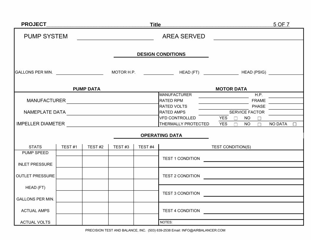
PROJECT__________________________________________________________________________________
__Title 5 OF 7
HEAD (FT)
THERMALLY PROTECTED YES NO NO DATA
NOTES:
TEST 3 CONDITION
TEST 4 CONDITION
YES NO
OPERATING DATA
AREA SERVEDPUMP SYSTEM
DESIGN CONDITIONS
SERVICE FACTOR
FRAMEH.P.
HEAD (PSIG)
PUMP DATA
ACTUAL VOLTS
ACTUAL AMPS
HEAD (FT)
GALLONS PER MIN.
OUTLET PRESSURE
INLET PRESSURE
MOTOR DATA
TEST 2 CONDITION
TEST 1 CONDITION
TEST CONDITION(S)
MANUFACTURERRATED RPMRATED VOLTS
VFD CONTROLLED
PHASERATED AMPS
MANUFACTURER
STATS
IMPELLER DIAMETER
TEST #2TEST #1
NAMEPLATE DATA
PUMP SPEED
MOTOR H.P.
TEST #4TEST #3
GALLONS PER MIN.
PRECISION TEST AND BALANCE, INC. (503) 639-2538 Email: [email protected]

PROJECT___________________________________________________________________Title 6 OF 7
DATE
DESIGN SET DIFF. SET DIFF. SET DIFF.SIZE GPM POINT PRESS. GPM % POINT PRESS. GPM % POINT PRESS. GPM %
TYPE OF NOTES
BALANCING
DEVICE
TEST #3 TEST #2
WATER MEASUREMENT BY REGULATING DEVICE
ELEMENTIDENTIFICATION
TESTED BYPUMP SYSTEMTEST #1
PRECISION TEST AND BALANCE, INC. (503) 639-2538 Email: [email protected]

PROJECT_____________________________________________________________________
_Title 7 OF 7
DATE
DIFF. DESIGN DIFF. DIFF. DIFF. DIFF.C.V. PRESS. GPM PRESS. GPM % PRESS. GPM % PRESS. GPM % PRESS. GPM %
TYPE OF NOTES
BALANCING
DEVICE
TEST #3TEST #2TEST #1DESIGN DATA
TESTED BY
WATER FLOW THROUGH FIXED RESTRICTION
TEST #4
IDENTIFICATIONELEMENT
PUMP SYSTEM
PRECISION TEST AND BALANCE, INC. (503) 639-2538 Email: [email protected]