BC 0055 TCPIP Protocol Suite - Weeblybscit2012.weebly.com/uploads/1/2/8/0/12803720/bt0076.pdf · BC...
223
BC 0055 TCPIP Protocol Suite Contents Unit 1 Architecture of TCP / IP 1 Unit 2 Network Interfaces 11 Unit 3 Internetworking Protocols 36 Unit 4 Transport Protocols 79 Unit 5 Domain Name System 104 Unit 6 Remote Execution 125 Unit 7 FTP and TFTP 133 Unit 8 Mail Applications 153 Unit 9 The Web 173 Unit 10 Network Management 188 Edition: Fall 2007 BKID – B0965 23 rd May 2009
Transcript of BC 0055 TCPIP Protocol Suite - Weeblybscit2012.weebly.com/uploads/1/2/8/0/12803720/bt0076.pdf · BC...

BC 0055 TCPIP Protocol Suite
Contents
Unit 1
Architecture of TCP / IP 1
Unit 2
Network Interfaces 11
Unit 3
Internetworking Protocols 36
Unit 4
Transport Protocols 79
Unit 5
Domain Name System 104
Unit 6
Remote Execution 125
Unit 7
FTP and TFTP 133
Unit 8
Mail Applications 153
Unit 9
The Web 173
Unit 10
Network Management 188
Edition: Fall 2007
BKID – B0965 23rd
May 2009

Department: Information Technology Program: BCA-New Prof. V. B. Nanda Gopal Director & Dean Directorate of Distance Education Sikkim Manipal University of Health, Medical & Technological Sciences
Board of Studies
1. Name Dr. U. B. Pavanaja
Designation General Manager – Academics
Organisation / Institution Manipal Universal Learning Pvt. Ltd.
Location Bangalore
2. Name Prof. Bhushan Patwardhan
Designation Chief Academics
Organisation / Institution Manipal Education
Location Bangalore
3. Name Dr. Harishchandra Hebbar
Designation Director
Organisation / Institution Manipal Centre for Information Sciences
Location Manipal
4. Name Dr. N. V. Subba Reddy
Designation Head of Department, Computer Science and Engineering
Organisation / Institution Manipal Institute of Technology
Location Manipal
5. Name Dr. Ashok Hegde
Designation Vice President
Organisation / Institution MindTree Consulting Ltd.
Location Bangalore

6. Name Dr. Ramprasad Varadachar
Designation Director, Computer Studies
Organisation / Institution Dayanand Sagar College of Engineering
Location Bangalore
7. Name Nirmal Kumar Nigam
Designation Head of Program, Information Technology
Organisation / Institution Sikkim Manipal University
Location Manipal
8. Name Dr. A. Kumaran
Designation Research Manager, Multilingual Research
Organisation / Institution Microsoft Research Labs India
Location Bangalore
9. Name Ravindranath P. S.
Designation Director, Quality
Organisation / Institution Yahoo India
Location Bangalore
10. Name Dr. Ashok Kallarakkal
Designation VP
Organisation / Institution IBM India
Location Bangalore
11. Name H. Hiriyannaiah
Designation Group Manager
Organisation / Institution EDS Mphasis
Location Bangalore

Program (s) : BCA Subject (s) : TCP/IP Protocol Suite Subject Code (s) : BC 0055
Content Preparation Team
Content writing / compilation
Name Mr. Santosh Rao
Designation Sr Lecturer, Dept. of ICT
Organisation / Institution MIT
Location Manipal
Content Editing
Name(s) Balasubramani R
Designation Asst. Professor, Dept. of IT
Organisation / Institution SMU – DDE
Location Manipal
Name(s) Nirmal Kumar Nigam
Designation Asst. Professor and HOP, Dept. of IT
Organisation / Institution SMU – DDE
Location Manipal
Language Editing
Name Ms. Aparna Ramanan
Designation Asst Professor
Organisation / Institution SMD – DDE
Location Manipal
Edition: Fall 2007 This book is a distance education module comprising of written and collated learning material for our students.
All rights reserved. No part of this work may be reproduced in any form by any means without permission in writing from Sikkim Manipal University of Health, Medical and Technological Sciences, Gangtok, Sikkim.
Printed and Published on behalf of Sikkim Manipal University of Health, Medical and Technological Sciences, Gangtok, Sikkim by Mr. Rajkumar Mascreen, GM, Manipal Universal Learning Pvt. Ltd., Manipal – 576 104. Printed at Manipal Press Limited, Manipal.

SUBJECT INTRODUCTION
Today, the internet and the World Wide Web (WWW) are well known terms
for millions of people all over the world. Many people depend on
applications enabled by the internet, such as electronic mail and web
access. In addition, the increase in popularity of business applications
places additional emphasis on the internet. The Transmission Control
Protocol/Internet Protocol (TCP/IP) protocol suite is the engine for the
Internet and networks worldwide. Its simplicity and power has leads it to
becoming the single network protocol of choice in the world today. The
whole book discusses TCP/IP suits and is divided into 10 units.
Unit 1: Architecture of TCP / IP
This unit speaks about The Internet standard Process, Request for
Comments, TCP/IP terminology, and different layers of TCP/IP Protocol
Suite.
Unit 2 : Network Interfaces
This unit speaks about the Ethernet : IEEE 802 LANs, Fiber Distributed data
Interface, Serial Line IP, Point-to-Point Protocol, Integrated services Digital
Networks (ISDN), X.25, Frame Relay, SONET and Asynchronous Transfer
Mode (ATM).
Unit 3: Internetworking Protocols
This unit speaks about Internet Protocol, Internet control Message Protocol,
Internet Group Management Protocol, Address Resolution Protocol,
Reverse Address resolution Protocol, Bootstrap Protocol and Dynamic host
configuration Protocol.
Unit 4: Transport protocols
This unit speaks about Ports and Sockets, User Datagram Protocol,
Transmission Control Protocol and TCP Congestion Control Algorithms.
Unit 5: Domain Name System
This unit speaks about Hierarchical namespace, Fully Qualified Names,
Mapping domain names to IP Addresses and vice versa. In addition to this
we also discuss about the distributed Name Space, Domain Name
Resolution, Domain Name Server Operation, Domain Name system
Resource Records and Messages.

Unit 6: Remote Execution
This unit speaks about Telnet, its Operation, Command structure and Basic
Telnet Commands and then about Remote Execution Command Protocol
(REXEC and RSH).
Unit 7: FTP and TFTP
This unit speaks about File Transfer Protocol, its operations and Trivial File
Transfer Protocol.
Unit 8: Mail Applications
This unit speaks about Simple Mail Transfer Protocol (SMTP), How it works,
its Header Format, its mail Transaction Flow, Post Office Protocol and about
Internet Message access Protocol.
Unit 9: The Web
This unit speaks about web browsers, web servers, and about Hypertext
Transfer Protocol.
Unit 10: Network Management
This unit speaks about The Simple Network Management Protocol (SNMP),
SNMP agent, SNMP Manager, SNMP Subagent, SNMP Model SNMP
Traps, SNMP Versions, Single Authentication and privacy Protocol and
about the NETSTAT Utilities.

TCPIP Protocol Suite Unit 1
Sikkim Manipal University Page No. 1
Unit 1 Architecture of TCP / IP
Structure 1.0 Introduction
1.1 The Internet Standard Process
1.2 Requests for Comments (RFCs)
1.3 TCP/IP Terminology
1.4 The TCP/IP Protocol Suite
Network Interface Layer
Internet Layer
Transport Layer
Application Layer
1.5 Summary
1.6 Terminal Questions
1.7 Answers for Self Assessment Questions
1.8 Answers for Terminal Questions
1.9 Exercises
1.0 Introduction Transmission Control Protocol/Internet Protocol (TCP/IP) is an industry
standard suite of protocols that is designed for large networks consisting of
network segments that are connected by routers. TCP/IP is the protocol that
is used on the Internet, which is the collection of thousands of networks
worldwide that connect research facilities, universities, libraries, government
agencies, private companies, and individuals. The roots of TCP/IP can be
traced back to research conducted by the United States Department of
Defense (DoD) Advanced Research Projects Agency (DARPA) in the late
1960s and early 1970s. The following list highlights some important TCP/IP
milestones:
In 1970, ARPANET hosts started to use Network Control Protocol
(NCP), a preliminary form of what would become the Transmission
Control Protocol (TCP).
In 1972, the Telnet protocol was introduced. Telnet is used for terminal
emulation to connect dissimilar systems. In the early 1970s, these
systems were different types of mainframe computers.

TCPIP Protocol Suite Unit 1
Sikkim Manipal University Page No. 2
In 1973, the File Transfer Protocol (FTP) was introduced. FTP is used to
exchange files between dissimilar systems.
In 1974, the Transmission Control Protocol (TCP) was specified in detail.
TCP replaced NCP and provided enhanced reliable communication
services.
In 1981, the Internet Protocol (IP) (also known as IP version 4 [IPv4])
was specified in detail. IP provides addressing and routing functions for
end-to-end delivery.
In 1982, the Defense Communications Agency (DCA) and ARPA
established the Transmission Control Protocol (TCP) and Internet
Protocol (IP) as the TCP/IP protocol suite.
In 1983, ARPANET switched from NCP to TCP/IP.
In 1984, the Domain Name System (DNS) was introduced. DNS
resolves domain names (such as www.example.com) to IP addresses
(such as 192.168.5.18).
In 1995, Internet Service Providers (ISPs) began to offer Internet access
to businesses and individuals.
In 1996, the Hypertext Transfer Protocol (HTTP) was introduced. The
World Wide Web uses HTTP.
In 1996, the first set of IP version 6 (IPv6) standards were published.
Objectives:
After completing this unit, you will be able to:
Describe the purpose and history of the TCP/IP protocol suite.
Describe the Internet standards process
Define common terms used in TCP/IP
Describe the Architecture of TCP/IP protocol suite
1.1 The Internet Standards Process
Because TCP/IP is the protocol of the Internet, it has evolved based on
fundamental standards that have been created and adopted over more than
30 years. The future of TCP/IP is closely associated with the advances and
administration of the Internet as additional standards continue to be
developed. Although no one organization owns the Internet or its
technologies, several organizations oversee and manage these new
standards, such as the Internet Society and the Internet Architecture Board.

TCPIP Protocol Suite Unit 1
Sikkim Manipal University Page No. 3
The Internet Society (ISOC) was created in 1992 and is a global
organization responsible for the internetworking technologies and
applications of the Internet. Although the society’s principal purpose is to
encourage the development and availability of the Internet, it is also
responsible for the further development of the standards and protocols that
allow the Internet to function. The ISOC sponsors the Internet Architecture
Board (IAB), a technical advisory group that sets Internet standards,
publishes RFCs, and oversees the Internet standards process. The IAB
governs the following bodies:
The Internet Assigned Number Authority (IANA) oversees and
coordinates the assignment of protocol identifiers used on the Internet.
The Internet Research Task Force (IRTF) coordinates all TCP/IP-
related research projects.
The Internet Engineering Task Force (IETF) solves technical problems
and needs as they arise on the Internet and develops Internet standards
and protocols. IETF working groups define standards known as RFCs.
Self Assessment Questions
1. The ----------------------------- oversees and coordinates the assignment of
protocol identifiers used on the Internet.
2. State TRUE/FALSE: TCP/IP is a protocol of the Internet.
1.2 Requests for Comments (RFCs) The standards for TCP/IP are published in a series of documents called
Requests for Comments (RFCs). RFCs describe the internal workings of the
Internet. TCP/IP standards are always published as RFCs, although not all
RFCs specify standards. Some RFCs provide informational, experimental,
or historical information only. An RFC begins as an Internet draft, which is
typically developed by one or more authors in an IETF working group. An
IETF working group is a group of individuals that has a specific charter for
an area of technology in the TCP/IP protocol suite.
1.3 TCP/IP Terminology
The Internet standards use a specific set of terms when referring to network
elements and concepts related to TCP/IP networking. These terms provide

TCPIP Protocol Suite Unit 1
Sikkim Manipal University Page No. 4
a foundation for subsequent chapters. Figure 1-1illustrates the components
of an IP network.
Common terms and concepts in TCP/IP are defined as follows:
Node: Any device, including routers and hosts, that runs an
implementation of IP.
Router: A node that can forward IP packets not explicitly addressed to
itself. On an IPv6 network, a router also typically advertises its presence
and host configuration information.
Host: A node that cannot forward IP packets not explicitly addressed to
itself (a non-router). A host is typically the source and the destination of
IP traffic. A host silently discards traffic that it receives but that is not
explicitly addressed to itself.
Upper – Layer Protocol: A protocol above IP that uses IP as its
transport. Examples include Internet layer protocols such as the Internet
Control Message Protocol (ICMP) and Transport layer protocols such
as the Transmission Control Protocol (TCP) and User Datagram
Protocol (UDP). (However, Application layer protocols that use TCP
and UDP as their transports are not considered upper-layer protocols.
File Transfer Protocol [FTP] and Domain Name System [DNS] fall
into this category).
LAN Segment: A portion of a subnet consisting of a single medium that
is bounded by bridges or Layer 2 switches.
Subnet: One or more LAN segments that are bounded by routers and
use the same IP address prefix. Other terms for subnet are network
segment and link.
Network: Two or more subnets connected by routers. Another term for
network is internetwork.
Neighbor: A node connected to the same subnet as another node.
Interface: The representation of a physical or logical attachment of a
node to a subnet. An example of a physical interface is a network
adapter. An example of a logical interface is a tunnel interface that is
used to send IPv6 packets across an IPv4 network.

TCPIP Protocol Suite Unit 1
Sikkim Manipal University Page No. 5
Address: An identifier that can be used as the source or destination of
IP packets and that is assigned at the Internet layer to an interface or set
of interfaces.
Packet: The protocol data unit (PDU) that exists at the Internet layer
and comprises an IP header and payload.
Fig. 1.1: Elements of an IP Network
Self Assessment Questions
1. A node that can forward IP packets not explicitly addressed to itself
is _________________ .
2. _____________ is a portion of a subnet consisting of a single medium
that is bounded by bridges or Layer 2 switches.
HOST HOST HOST
SWITCH / BRIDGE
Neighbors
LAN Segment
ROUTER
Additional Subnets
Network
Subnet

TCPIP Protocol Suite Unit 1
Sikkim Manipal University Page No. 6
1.4 The TCP/IP Protocol Suite The TCP/IP protocol suite maps to a four-layer conceptual model known as
the DARPA model, which was named after the U.S. government agency that
initially developed TCP/IP. The four layers of the DARPA model are:
Application, Transport, Internet, and Network Interface. Each layer in the
DARPA model corresponds to one or more layers of the seven-layer OSI
model.
Figure 1.2 shows the architecture of the TCP/IP protocol suite.
The TCP/IP protocol suite has two sets of protocols at the Internet layer:
IPv4, also known as IP, is the Internet layer in common use today on private
intranets and the Internet. IPv6 is the new Internet layer that will eventually
replace the existing IPv4 Internet layer.
Fig. 1.2: TCP/IP Protocol Stack
1.4.1 Network Interface Layer
The Network Interface Layer (also called the Network Access Layer)
sends TCP/IP packets on the network medium and receives TCP/IP packets
off the network medium. TCP/IP was designed to be independent of the
network access method, frame format, and medium. Therefore, you can use
TCP/IP to communicate across differing network types that use LAN
technologies – such as Ethernet and 802.11 wireless LAN – and WAN
technologies – such as Frame Relay and Asynchronous Transfer Mode

TCPIP Protocol Suite Unit 1
Sikkim Manipal University Page No. 7
(ATM). By being independent of any specific network technology, TCP/IP
can be adapted to new technologies. The Network Interface layer of the
DARPA model encompasses the Data Link and Physical layers of the OSI
model. The Internet layer of the DARPA model does not take advantage of
sequencing and acknowledgment services that might be present in the Data
Link layer of the OSI model. The Internet layer assumes an unreliable
Network Interface layer and that reliable communications through session
establishment and the sequencing and acknowledgment of packets is the
responsibility of either the Transport layer or the Application layer.
Self Assessment Questions
1. The Network Interface layer of the DARPA model encompasses the
________________ and Physical layers of the OSI model.
1.4.2 Internet Layer
The Internet layer responsibilities include addressing, packaging, and
routing functions. The Internet layer is analogous to the Network layer of the
OSI model. The core protocols for the IPv4 Internet layer consist of the
following:
The Address Resolution Protocol (ARP) resolves the Internet layer
address to a Network Interface layer address such as a hardware
address.
The Internet Protocol (IP) is a routable protocol that addresses, routes,
fragments and reassembles packets.
The Internet Control Message Protocol (ICMP) reports errors and other
information to help you diagnose unsuccessful packet delivery.
The Internet Group Management Protocol (IGMP) manages IP multicast
groups.
Self Assessment Questions
1. The ________________ reports errors and other information to help you
diagnose unsuccessful packet delivery.
1.4.3 Transport Layer
The Transport layer (also known as the Host-to-Host Transport layer)
provides the Application layer with session and datagram communication
services. The Transport layer encompasses the responsibilities of the OSI
Transport layer. The core protocols of the Transport layer are TCP and
TCPIP Protocol Suite Unit 1
Sikkim Manipal University Page No. 8
UDP. TCP provides a one-to-one, connection-oriented, reliable
communications service. TCP establishes connections, sequences and
acknowledges packets sent, and recovers packets lost during transmission.
In contrast to TCP, UDP provides a one-to-one or one-to-many,
connectionless, unreliable communications service. UDP is used when the
amount of data to be transferred is small (such as the data that would fit into
a single packet), when an application developer does not want the overhead
associated with TCP connections, or when the applications or upper-layer
protocols provide reliable delivery. TCP and UDP operate over both IPv4
and IPv6 Internet layers.
Self Assessment Questions
1. The core protocols of the Transport layer are ________________ .
2. The ____________ transport protocol is used when the amount of data
to be transferred is small (such as the data that would fit into a single
packet),
1.4.4 Application Layer
The Application layer allows applications to access the services of the other
layers, and it defines the protocols that applications use to exchange data.
The Application layer contains many protocols, and more are always being
developed. The most widely known Application layer protocols help users
exchange information:
The Hypertext Transfer Protocol (HTTP) transfers files that make up
pages on the World Wide Web.
The File Transfer Protocol (FTP) transfers individual files, typically for
an interactive user session.
The Simple Mail Transfer Protocol (SMTP) transfers mail messages
and attachments. Additionally, the following Application layer protocols
help you use and manage TCP/IP networks:
The Domain Name System (DNS) protocol resolves a host name, such
a www.cisco.com, to an IP address and copies name information
between DNS servers.
The Routing Information Protocol (RIP) is a protocol that routers use
to exchange routing information on an IP network.
The Simple Network Management Protocol (SNMP) collects and
exchanges network management information between a network

TCPIP Protocol Suite Unit 1
Sikkim Manipal University Page No. 9
management console and network devices such as routers, bridges, and
servers.
Windows Sockets and NetBIOS are examples of Application layer
interfaces for TCP/IP applications.
Self Assessment Questions
1. The ________________ transfers mail messages and attachments.
Additionally, the following Application layer protocols help you use and
manage TCP/IP networks.
2. The _____________ protocol resolves a host name, such a
www.cisco.com, to an IP address.
1.5 Summary TCP/IP is the protocol that is used on the Internet, which is the collection of
thousands of networks worldwide that connect research facilities,
universities, libraries, government agencies, private companies, and
individuals. The TCP/IP protocol suite maps to a four-layer conceptual
model known as the DARPA model. The Network Interface layer sends
TCP/IP packets on the network medium and receives TCP/IP packets off
the network medium. The Internet layer responsibilities include addressing,
packaging, and routing functions. The Transport layer provides the
Application layer with session and datagram communication services. The
Application layer allows applications to access the services of the other
layers
1.6 Terminal Questions 1. The _______________ manages IP multicast groups.
2. ________________ working groups define standards known as RFCs.
3. __________________ transport protocol establishes connections,
sequences and acknowledges packets sent, and recovers packets lost
during transmission
1.7 Answers for Self Assessment Questions 1.1 1) IANA
2) TRUE
1.3 1) router
2) LAN segment

TCPIP Protocol Suite Unit 1
Sikkim Manipal University Page No. 10
1.4.1 1) data link
1.4.2 1) ICMP
1.4.3 1) TCP and UDP
2) UDP
1.4.4 1) SNMP
2) DNS
1.8 Answers for Terminal Questions
1. IGMP
2. IETF
3. TCP
1.9 Exercises 1. Briefly discuss the functions of transport layer.
2. What do you mean by RFC? Explain its significance.
3. List the core protocols in IPV4 layer.

TCPIP Protocol Suite Unit 2
Sikkim Manipal University Page No. 11
Unit 2 Network Interfaces
Structure
2.1 Introduction
2.2 Ethernet and IEEE 802 Local Area Networks (LANs)
Gigabit Ethernet
2.3 Fiber Distributed Data Interface (FDDI)
2.4 Serial Line IP (SLIP)
2.5 Point-to-Point Protocol (PPP)
Point-to-point Encapsulation
2.6 Integrated Services Digital Network (ISDN)
2.7 X.25
2.8 Frame relay
Frame Format
Interconnect issues
Data link layer parameter negotiation
2.9 PPP over SONET and SDH Circuits
Physical Layer
2.10 Asynchronous Transfer Mode (ATM)
Address Resolution
Classical IP over ATM
2.11 Summary
2.12 Terminal Questions
2.13 Answers for Self Assessment Questions
2.14 Answers for Terminal Questions
2.15 Exercises
2.1 Introduction
This chapter provides an overview of the protocols and interfaces that allow
TCP/IP traffic to flow over various kinds of physical networks. TCP/IP, as an
internetwork protocol suite, can operate over a vast number of physical
networks. The most common and widely used of these protocols is, of
course, Ethernet. Also, we provide a summary of some of the different
networks most commonly used with TCP/IP.

TCPIP Protocol Suite Unit 2
Sikkim Manipal University Page No. 12
Objectives:
After the completion of this chapter you will be able to understand:
Ethernet Standard
FDDI Specifications
X.25
ISDN Basics
Frame Relay and ATM
SLIP and PPP Protocols
2.2 Ethernet and IEEE 802 Local Area Networks (LANs)
Two frame formats (or standards) can be used on the Ethernet coaxial
cable. The standard issued in 1978 by Xerox Corporation, Intel Corporation,
and Digital Equipment Corporation, usually called Ethernet (or DIX
Ethernet). The international IEEE 802.3 standard, a more recently defined
standard.
Fig. 2.1: ARP: Frame formats for Ethernet and IEEE 802.3
The difference between the two standards is in the use of one of the header
fields, which contains a protocol-type number for Ethernet and the length of
the data in the frame for IEEE 802.3 (See Fig. 2.1). The type field in
Ethernet is used to distinguish between different protocols running on the
coaxial cable, and allows their coexistence on the same physical cable. The
maximum length of an Ethernet frame is 1526 bytes. This means a data field
length of up to 1500 bytes. The length of the 802.3 data field is also limited
to 1500 bytes for 10 Mbps networks, but is different for other transmission
speeds. In the 802.3 MAC frame, the length of the data field is indicated in

TCPIP Protocol Suite Unit 2
Sikkim Manipal University Page No. 13
the 802.3 header. The type of protocol it carries is then indicated in the
802.2 header. In practice, however, both frame formats can coexist on the
same physical coaxial. This is done by using protocol type numbers (type
field) greater than 1500 in the Ethernet frame. However, different device
drivers are needed to handle each of these formats. Therefore, for all
practical purposes, the Ethernet physical layer and the IEEE 802.3 physical
layers are compatible. However, the Ethernet data link layer and the IEEE
802.3/802.2 data link layers are incompatible. The 802.2 Logical Link
Control (LLC) layer above IEEE 802.3 uses a concept known as link service
access point (LSAP), which uses a 3-byte header, where DSAP and SSAP
stand for destination and source service access point, respectively.
Numbers for these fields are assigned by an IEEE committee (see Fig. 2.2).
Fig. 2.2: ARP: IEEE 802.2 LSAP Header
Due to a growing number of applications using IEEE 802 as lower protocol
layers, an extension was made to the IEEE 802.2 protocol in the form of the
Subnetwork Access Protocol (SNAP) (see Fig. 2.3). It is an extension to the
LSAP header in Fig. 2.2, and its use is indicated by the value 170 in both
the SSAP and DSAP fields of the LSAP frame Fig. 2.3.
Fig. 2.3: ARP: IEEE 802.2 SNAP Header
2.2.1 Gigabit Ethernet
As advances in hardware continue to provide faster transmissions across
networks, Ethernet implementations have improved in order to capitalize on
the faster speeds. Fast Ethernet increased the speed of traditional Ethernet

TCPIP Protocol Suite Unit 2
Sikkim Manipal University Page No. 14
from 10 megabits per second (Mbps) to 100 Mbps. This was further
augmented to 1000 Mbps in June of 1998, when the IEEE defined the
standard for Gigabit Ethernet (IEEE 802.3z). Finally, in 2005, IEEE created
the 802.3-2005 standard introduced 10 Gigabit Ethernet, also referred to as
10GbE. 10GbE provides transmission speeds of 10 gigabits per second
(Gbps), or 10000 Mbps, 10 times the speed of Gigabit Ethernet. However,
due to the novelty of 10GbE, there are still limitations on the adapters over
which 10GbE can be used, and no one implementation standard has yet
gained commercial acceptance.
Self Assessment Questions
1. The ________________ field in Ethernet is used to distinguish between
different protocols running on the coaxial cable, and allows their
coexistence on the same physical cable.
2. State TRUE/FALSE: For all practical purposes, the Ethernet physical
layer and the IEEE 802.3 physical layers are compatible.
3. ____________ increased the speed of traditional Ethernet from 10
megabits per second (Mbps) to 100 Mbps.
2.3 Fiber Distributed Data Interface (FDDI)
The FDDI specifications define a family of standards for 100 Mbps fiber
optic LANs that provides the physical layer and media access control sub-
layer of the data link layer, as defined by the ISO/OSI Model. Proposed
initially by draft-standard RFC 1188, IP and ARP over FDDI networks
became a standard in RFC 1390. It defines the encapsulating of IP
datagrams and ARP requests and replies in FDDI frames. RFC 2467
extended this standard in order to allow the transmission of IPv6 packets
over FDDI networks. Operation on dual MAC stations is described in
informational RFC 1329. Fig. 2.4 shows the related protocol layers.
The 24-bit Organization Code in the SNAP header is set to zero, and the
remaining 16 bits are the EtherType (used to indicate which protocol is
being transported in an Ethernet frame) from Assigned Numbers, that is:
2048 for IP and 2054 for ARP. The mapping of 32-bit Internet addresses to
48-bit FDDI addresses is done through the ARP dynamic discovery
procedure. The broadcast Internet addresses (whose host address is set to
all ones) are mapped to the broadcast FDDI address (all ones). IP

TCPIP Protocol Suite Unit 2
Sikkim Manipal University Page No. 15
datagrams are transmitted as series of 8-bit bytes using the usual TCP/IP
transmission order called big-endian or network byte order. The FDDI MAC
specification (ISO 9314-2 - ISO, Fiber Distributed Data Interface – Media
Access Control) defines a maximum frame size of 4500 bytes for all frame
fields. After taking the LLC/SNAP header into account, and to allow future
extensions to the MAC header and frame status fields, the MTU of FDDI
networks is set to 4352 bytes.
Fig. 2.4: IP and ARP over FDDI
Self Assessment Questions
1. The FDDI specifications define a family of standards for 100 Mbps fiber
optic LANs that provides the physical layer and _________ sublayer of
the data link layer.
2. The mapping of 32-bit Internet addresses to 48-bit FDDI addresses is
done through the __________.
2.4 Serial Line IP (SLIP)
The TCP/IP protocol family runs over a variety of network media: IEEE
802.3 and 802.5 LANs, X.25 lines, satellite links, and serial lines. Standards
for the encapsulation of IP packets have been defined for many of these
networks, but there is no standard for serial lines. SLIP is currently a de
facto standard, commonly used for point-to-point serial connections running
TCP/IP. Even though SLIP is not an Internet standard, it is documented by
RFC 1055. SLIP is just a very simple protocol designed quite a long time
ago and is merely a packet framing protocol. It defines a sequence of
characters that frame IP packets on a serial line, and nothing more.

TCPIP Protocol Suite Unit 2
Sikkim Manipal University Page No. 16
Both computers on a SLIP link need to know each other's IP address for
routing purposes. SLIP defines only the encapsulation protocol, not any
form of handshaking or link control. Links are manually connected and
configured, including the specification of the IP address. SLIP cannot
support multiple protocols across a single link; thus, only one protocol can
be run over a SLIP connection. SLIP does no form of frame error detection.
The higher-level protocols should detect corrupted packets caused by errors
on noisy lines. (IP header and UDP/TCP checksums should be sufficient.)
Because it takes so long to retransmit a packet that was altered, it would be
efficient if SLIP could provide some sort of simple error correction
mechanism of its own. SLIP provides no mechanism for compressing
frequently used IP header fields. Many applications over slow serial links
tend to be single-user interactive TCP traffic, such as Telnet. This frequently
involves small packet sizes and inefficiencies in TCP and IP headers that do
not change much between datagrams, but that can have a noticeably
detrimental effect on interactive response times. However, many SLIP
implementations now use Van Jacobson Header Compression. This is used
to reduce the size of the combined IP and TCP headers from 40 bytes to 3-4
bytes by recording the states of a set of TCP connections at each end of the
link and replacing the full headers with encoded updates for the normal
case, where many of the fields are unchanged or are incremented by small
amounts between successive IP datagrams for a session. The SLIP protocol
has been essentially replaced by the Point-to-Point Protocol (PPP), as
described in the following section.
Self Assessment Questions
1. State TRUE/FALSE: SLIP can support multiple protocols across a single
link.
2. Both computers on a SLIP link need to know each other's IP address for
____________ purposes.
2.5 Point-to-Point Protocol (PPP)
Point-to-Point Protocol (PPP) is a network-specific standard protocol and it
is described in RFC 1661 and RFC 1662.
There are a large number of proposed standard protocols, which specify the
operation of PPP over different kinds of point-to-point links. Each has a

TCPIP Protocol Suite Unit 2
Sikkim Manipal University Page No. 17
status of elective. Point-to-point circuits in the form of asynchronous and
synchronous lines have long been the mainstay for data communications. In
the TCP/IP world, the de facto standard SLIP protocol has served admirably
in this area, and is still in widespread use for dial-up TCP/IP connections.
However, SLIP has a number of drawbacks that are addressed by the Point-
to-Point Protocol. PPP has three main components:
A method for encapsulating datagrams over serial links.
A Link Control Protocol (LCP) for establishing, configuring, and testing
the data-link connection.
A family of Network Control Protocols (NCPs) for establishing and
configuring different network-layer protocols.
PPP is designed to allow the simultaneous use of multiple network-layer
protocols. Before a link is considered to be ready for use by network-layer
protocols, a specific sequence of events must happen. The LCP provides a
method of establishing, configuring, maintaining, and terminating the
connection. LCP goes through the following phases:
1. Link Establishment and Configuration Negotiation: In this phase, link
control packets are exchanged and link configuration options are
negotiated. After options are agreed on, the link is open, but is not
necessarily ready for network-layer protocols to be started.
2. Link Quality Determination: This phase is optional. PPP does not
specify the policy for determining quality, but does provide low-level
tools, such as echo request and reply.
3. Authentication: This phase is optional. Each end of the link
authenticates itself with the remote end using authentication methods
agreed to during phase 1.
4. Network – layer Protocol Configuration Negotiation: After LCP has
finished the previous phase, network-layer protocols can be separately
configured by the appropriate NCP.
5. Link Termination: LCP can terminate the link at any time. This is
usually done at the request of a human user, but can happen because of
a physical event.
TCPIP Protocol Suite Unit 2
Sikkim Manipal University Page No. 18
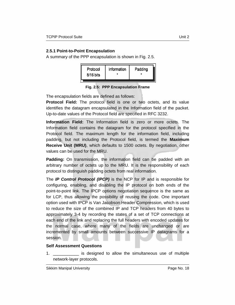
2.5.1 Point-to-Point Encapsulation
A summary of the PPP encapsulation is shown in Fig. 2.5.
Fig. 2.5: PPP Encapsulation Frame
The encapsulation fields are defined as follows:
Protocol Field: The protocol field is one or two octets, and its value
identifies the datagram encapsulated in the Information field of the packet.
Up-to-date values of the Protocol field are specified in RFC 3232.
Information Field: The Information field is zero or more octets. The
Information field contains the datagram for the protocol specified in the
Protocol field. The maximum length for the information field, including
padding, but not including the Protocol field, is termed the Maximum
Receive Unit (MRU), which defaults to 1500 octets. By negotiation, other
values can be used for the MRU.
Padding: On transmission, the information field can be padded with an
arbitrary number of octets up to the MRU. It is the responsibility of each
protocol to distinguish padding octets from real information.
The IP Control Protocol (IPCP) is the NCP for IP and is responsible for
configuring, enabling, and disabling the IP protocol on both ends of the
point-to-point link. The IPCP options negotiation sequence is the same as
for LCP, thus allowing the possibility of reusing the code. One important
option used with IPCP is Van Jacobson Header Compression, which is used
to reduce the size of the combined IP and TCP headers from 40 bytes to
approximately 3-4 by recording the states of a set of TCP connections at
each end of the link and replacing the full headers with encoded updates for
the normal case, where many of the fields are unchanged or are
incremented by small amounts between successive IP datagrams for a
session.
Self Assessment Questions
1. ___________ is designed to allow the simultaneous use of multiple
network-layer protocols.

TCPIP Protocol Suite Unit 2
Sikkim Manipal University Page No. 19
2. The _____________ is the NCP for IP and is responsible for
configuring, enabling, and disabling the IP protocol on both ends of the
point-to-point link.
2.6 Integrated Services Digital Network (ISDN)
This section describes how to use the PPP encapsulation over ISDN point-
to-point links. PPP over ISDN is documented by elective RFC 1618.
Because the ISDN B-channel is, by definition, a point-to-point circuit, PPP is
well suited for use over these links.
The ISDN Basic Rate Interface (BRI) usually supports two B-channels with
a capacity of 64 kbps each, and a 16 kbps D-channel for control information.
B-channels can be used for voice or data or just for data in a combined way.
The ISDN Primary Rate Interface (PRI) can support many concurrent
B-channel links and one 64 Kbps D-channel. The PPP, LCP and NCP
mechanisms are particularly useful in this situation in reducing or eliminating
manual configuration and facilitating ease of communication between
diverse implementations. The ISDN D-channel can also be used for sending
PPP packets when suitably framed, but is limited in bandwidth and often
restricts communication links to a local switch. PPP treats ISDN channels as
bit- or octet-oriented synchronous links. These links must be full-duplex, but
can be either dedicated or circuit-switched. PPP presents an octet interface
to the physical layer. There is no provision for sub-octets to be supplied or
accepted. PPP does not impose any restrictions regarding transmission rate
other than that of the particular ISDN channel interface. PPP does not
require the use of control signals. When available, using such signals can
allow greater functionality and performance.
The definition of various encodings and scrambling is the responsibility of
the DTE/DCE equipment in use(DTE means Data Terminal Equipment and
DCE means Data Communication Equipment). While PPP will operate
without regard to the underlying representation of the bit stream, lack of
standards for transmission will hinder interoperability as surely as lack of
data link standards. The D-channel interface requires Non-Return-To-Zero
(NRZ) encoding. Therefore, it is recommended that NRZ be used over the
B-channel interface. This will allow frames to be easily exchanged between
the B- and D-channels. However, when the configuration of the encoding is
allowed, NRZ Inverted (NRZI) is recommended as an alternative in order to

TCPIP Protocol Suite Unit 2
Sikkim Manipal University Page No. 20
ensure a minimum ones density where required over the clear B-channel.
Implementations that want to interoperate with multiple encodings can
choose to detect those encodings automatically. Automatic encoding
detection is particularly important for primary rate interfaces to avoid
extensive pre-configuration. Terminal adapters conforming to V.1201 can be
used as a simple interface to workstations. The terminal adapter provides
asynchronous-to-synchronous conversion. Multiple B-channels can be used
in parallel. V.120 is not interoperable with bit-synchronous links, because
V.120 does not provide octet stuffing to bit stuffing conversion. Despite the
fact that HDLC, LAPB, LAPD, and LAPF are nominally distinguishable,
multiple methods of framing should not be used concurrently on the same
ISDN channel. HDLC is a bit-oriented, synchronous data communications
protocol developed by the International Organization for Standardization
(ISO) as a superset of Synchronous Data Link Control (SDLC) and
Advanced Data Communications Control Procedures (ADCCP). A version of
HDLC is the Link Access Procedure-Balanced (LAPB), which is used in
packet-switched networks conforming to the ITU-T X.25 Recommendation.
HDLC also was imported into other standards, including ISDN as LAPD and
frame relay as LAPF. There is no requirement that PPP recognize
alternative framing techniques, or switch between framing techniques
without specific configuration. Experience has shown that the LLC (Logical
Link Control) Information Element is not reliably transmitted end to end.
Therefore, transmission of the LLC-IE should not be relied upon for framing
or encoding determination. No LLC-IE values that pertain to PPP have been
assigned. Any other values that are received are not valid for PPP links, and
can be ignored for PPP service. The LCP recommended sync configuration
options apply to ISDN links. The standard LCP sync configuration defaults
apply to ISDN links. The typical network connected to the link is likely to
have an MRU size of either 1500 or 2048 bytes or greater. To avoid
fragmentation, the Maximum Transmission Unit (MTU) at the network
layer should not exceed 1500, unless a peer MRU of 2048 or greater is
specifically negotiated.

TCPIP Protocol Suite Unit 2
Sikkim Manipal University Page No. 21
Self Assessment Questions
1. The ISDN Basic Rate Interface (BRI) usually supports two B-channels
with a capacity of ____________ each.
2. The D-channel interface requires _____________ encoding.
2.7 X.25
This topic describes the encapsulation of IP over X.25 networks, in
accordance with ISO/IEC and CCITT standards. IP over X.25 networks is
documented by RFC 1356 (which obsoletes RFC 877). RFC 1356 is a Draft
Standard with a status of elective. The substantive change to the IP
encapsulation over X.25 is an increase in the IP datagram MTU size, the
X.25 maximum data packet size, the virtual circuit management, and the
interoperable encapsulation over X.25 of protocols other than IP between
multi-protocol routers and bridges. One or more X.25 virtual circuits are
opened on demand when datagrams arrive at the network interface for
transmission. Protocol Data Units (PDUs) are sent as X.25 complete
packet sequences. That is, PDUs begin on X.25 data packet boundaries
and the M bit (more data) is used to fragment PDUs that are larger than one
X.25 data packet in length. In the IP encapsulation, the PDU is the IP
datagram. The first octet in the Call User Data (CUD) field (the first data
octet in the Call Request packet) is used for protocol de-multiplexing in
accordance with the Subsequent Protocol Identifier (SPI) in ISO/IEC TR
9577. This field contains a one octet Network-Layer Protocol Identifier
(NLPID), which identifies the network-layer protocol encapsulated over the
X.25 virtual circuit.
For the Internet community, the NLPID has four relevant values: The value
hex CC (binary 11001100, decimal 204) is IP. The value hex 81 (binary
10000001, decimal 129) identifies ISO/IEC 8473 (CLNP).The value hex 82
(binary 10000010, decimal 130) is used specifically for ISO/IEC 9542
(ES-IS). If there is already a circuit open to carry CLNP, it is not necessary
to open a second circuit to carry ES-IS. The value hex 80 (binary 10000000,
decimal 128) identifies the use of the IEEE Subnetwork Access Protocol
(SNAP) to further encapsulate and identify a single network-layer protocol.
The SNAP-encapsulated protocol is identified by including a five-octet
SNAP header in the Call Request CUD field immediately following the hex
80 octet. SNAP headers are not included in the subsequent X.25 data

TCPIP Protocol Suite Unit 2
Sikkim Manipal University Page No. 22
packets. Only one SNAP-encapsulated protocol can be carried over a virtual
circuit opened using this encoding. The value hex 00 identifies the null
encapsulation used to multiplex multiple network-layer protocols over the
same circuit. RFC 3232 contains one other non-CCITT and non-ISO/IEC
value that has been used for Internet X.25 encapsulation identification,
namely hex C5 (binary 11000101, decimal 197) for Blacker X.25. This value
may continue to be used, but only by prior pre-configuration of the sending
and receiving X.25 interfaces to support this value. The hex CD (binary
11001101, decimal 205), listed in RFC 3232 for ISO-IP, is also used by
Blacker and can only be used by prior pre-configuration of the sending and
receiving X.25 interfaces. Each system must only accept calls for protocols
it can process. Every Internet system must be able to accept the CC
encapsulation for IP datagrams. Systems that support NLPIDs other than
hex CC (for IP) should allow their use to be configured on a per-peer
address basis. The Null encapsulation, identified by a NLPID encoding of
hex 00, is used in order to multiplex multiple network-layer protocols over
one circuit. When the Null encapsulation is used, each X.25 complete
packet sequence sent on the circuit begins with a one-octet NLPID, which
identifies the network-layer protocol data unit contained only in that
particular complete packet sequence. Further, if the SNAP NLPID (hex 80)
is used, the NLPID octet is immediately followed by the five-octet SNAP
header, which is then immediately followed by the encapsulated PDU. The
encapsulated network-layer protocol can differ from one complete packet
sequence to the next over the same circuit. Use of the single network-layer
protocol circuits is more efficient in terms of bandwidth if only a limited
number of protocols are supported by a system. It also allows each system
to determine exactly which protocols are supported by its communicating
partner. Other advantages include being able to use X.25 accounting to
detail each protocol and different quality of service or flow control windows
for different protocols. The Null encapsulation, for multiplexing, is useful
when a system, for any reason (such as implementation restrictions or
network cost considerations), can only open a limited number of virtual
circuits simultaneously. This is the method most likely to be used by a multi-
protocol router to avoid using an unreasonable number of virtual circuits.
If performing IEEE 802.1d bridging across X.25 is required, the Null
encapsulation must be used. IP datagrams must, by default, be

TCPIP Protocol Suite Unit 2
Sikkim Manipal University Page No. 23
encapsulated on a virtual circuit opened with the CC CUD. Implementations
can also support up to three other possible encapsulations of IP.
IP datagrams can be contained in multiplexed data packets on a circuit
using the Null encapsulation. Such data packets are identified by a
NLPID of hex CC.
IP can be encapsulated within the SNAP encapsulation on a circuit.
This encapsulation is identified by containing, in the 5-octet SNAP
header, an Organizationally Unique Identifier (OUI) of hex 00-00-00 and
Protocol Identifier (PID) of hex 08-00.
On a circuit using the Null encapsulation, IP can be contained within the
SNAP encapsulation of IP in multiplexed data packets.
Self Assessment Questions
1. Every Internet system must be able to accept the _________
encapsulation for IP datagrams.
2. If performing IEEE 802.1d bridging across X.25 is required, the _______
encapsulation must be used.
2.8 Frame Relay
The frame relay network provides a number of virtual circuits that form the
basis for connections between stations attached to the same frame relay
network. The resulting set of interconnected devices forms a private frame
relay group, which can be either fully interconnected with a complete mesh
of virtual circuits, or only partially interconnected. In either case, each virtual
circuit is uniquely identified at each frame relay interface by a Data Link
Connection Identifier (DLCI). In most circumstances, DLCIs have strictly
local significance at each frame relay interface. Frame relay is documented
in RFC 2427, and is expanded in RFC 2590 to allow the transmission of
IPv6 packets.
2.8.1 Frame Format
Frames contain the necessary information to identify the protocol carried
within the protocol data unit (PDU), thus allowing the receiver to properly
process the incoming packet (refer to Fig. 2.6). The format will be as follows:
The control field is the Q.922 control field. The UI (0x03) value is used
unless it is negotiated otherwise. The use of XID (0xAF or 0xBF) is
permitted.

TCPIP Protocol Suite Unit 2
Sikkim Manipal University Page No. 24
The pad field is used to align the data portion (beyond the encapsulation
header) of the frame to a two octet boundary. If present, the pad is a single
octet and must have a value of zero.
The Network Level Protocol ID (NLPID) field is administered by ISO and the
ITU. It contains values for many different protocols, including IP, CLNP, and
IEEE Subnetwork Access Protocol (SNAP). This field tells the receiver what
encapsulation or what protocol follows. Values for this field are defined in
ISO/IEC TR 95773. An NLPID value of 0x00 is defined within ISO/IEC TR
9577 as the null network layer or inactive set. Because it cannot be
distinguished from a pad field, and because it has no significance within the
context of this encapsulation scheme, an NLPID value of 0x00 is invalid
under the frame relay encapsulation.
There is no commonly implemented minimum or maximum frame size for
frame relay. A network must, however, support at least a 262-octet
maximum. Generally, the maximum will be greater than or equal to 1600
octets, but each frame relay provider will specify an appropriate value for its
network. A frame relay data terminal equipment (DTE) must allow the
maximum acceptable frame size to be configurable.
Fig. 2.6: Frame relay packet format

TCPIP Protocol Suite Unit 2
Sikkim Manipal University Page No. 25
2.8.2 Interconnect Issues
There are two basic types of data packets that travel within the frame relay
network: routed packets and bridged packets. These packets have distinct
formats and must contain an indicator that the destination can use to
correctly interpret the contents of the frame. This indicator is embedded
within the NLPID and SNAP header information.
2.8.3 Data Link Layer Parameter Negotiation
Frame relay stations may choose to support the Exchange Identification
(XID) which allows the following parameters to be negotiated at the
initialization of a frame relay circuit: maximum frame size, retransmission
timer, and the maximum number of outstanding information (I) frames.
There are situations in which a frame relay station might want to dynamically
resolve a protocol address over Permanent Virtual Circuits (PVCs). This
can be accomplished using the standard Address Resolution Protocol
(ARP) encapsulated within a SNAP-encoded frame relay packet.
Because of the inefficiencies of emulating broadcasting in a frame relay
environment, a new address resolution variation was developed. It is called
Inverse ARP, and describes a method for resolving a protocol address when
the hardware address is already known. In a frame relay network, the known
hardware address is the DLCI. Support for Inverse ARP is not required to
implement this specification, but it has proven useful for frame relay
interface autoconfiguration. Stations must be able to map more than one IP
address in the same IP subnet to a particular DLCI on a frame relay
interface. This need arises from applications such as remote access, where
servers must act as ARP proxies for many dial-in clients, each assigned a
unique IP address while sharing bandwidth on the same DLC. The dynamic
nature of such applications results in frequent address association changes
with no effect on the DLC's status. As with any other interface that uses
ARP, stations can learn the associations between IP addresses and DLCIs
by processing unsolicited (gratuitous) ARP requests that arrive on the DLC.
If one station wants to inform its peer station on the other end of a frame
relay DLC of a new association between an IP address and that PVC, it
should send an unsolicited ARP request with the source IP address equal to
the destination IP address, and both set to the new IP address being used
on the DLC. This allows a station to “announce” new client connections on a
particular DLCI. The receiving station must store the new association, and

TCPIP Protocol Suite Unit 2
Sikkim Manipal University Page No. 26
remove any old existing association, if necessary, from any other DLCI on
the interface.
2.8.4 IP over frame relay
Internet Protocol (IP) datagrams sent over a frame relay network conform to
the encapsulation described previously. Within this context, IP can be
encapsulated in two different ways: NLPID value, indicating IP, or NLPID
value, indicating SNAP.
Although both of these encapsulations are supported under the given
definitions, it is advantageous to select only one method as the appropriate
mechanism for encapsulating IP data. Therefore, encapsulate IP data using
the NLPID value of 0xcc, indicating an IP packet. This option is more
efficient, because it transmits 48 fewer bits without the SNAP header and is
consistent with the encapsulation of IP in an X.25 network.
Self Assessment Questions
1. State TRUE/FALSE: DLCIs have strictly local significance at each frame
relay interface.
2.9 PPP over SONET and SDH circuits
This discussion describes the use of the PPP encapsulation over
Synchronous Optical Network (SONET) and Synchronous Digital Hierarchy
(SDH) links, which is documented by RFC 2615. Because SONET and SDH
are, by definition, point-to-point circuits, PPP is well suited for use over
these links. SONET is an octet-synchronous multiplex scheme that defines
a family of standard rates and formats. Despite the name, it is not limited to
optical links. Electrical specifications have been defined for single-mode
fiber, multimode fiber, and CATV 75 ohm coaxial cable. The transmission
rates are integral multiples of 51.840 Mbps, which can be used to carry
T3/E3 bit-synchronous signals.
2.9.1 Physical layer
PPP presents an octet interface to the physical layer. There is no provision
for sub-octets to be supplied or accepted. SONET and SDH links are full-
duplex by definition. The octet stream is mapped into the SONET/SDH
Synchronous Payload Envelope (SPE) with the octet boundaries aligned
with the SPE octet boundaries. No scrambling is needed during insertion
into the SPE. The path signal label is intended to indicate the contents of the

TCPIP Protocol Suite Unit 2
Sikkim Manipal University Page No. 27
SPE. The experimental value of 207 (hex CF) is used to indicate PPP. The
multiframe indicator is currently unused and must be zero.
The basic rate for PPP over SONET/SDH is that of STS-3c/STM-1 at 155.52
Mbps. The available information bandwidth is 149.76 Mbps, which is the
STS-3c/STM-1 SPE with section, line, and path inefficiencies removed. This
is the same upper layer mapping that is used for ATM and FDDI. Lower
signal rates must use the Virtual Tributary (VT) mechanism of SONET/SDH.
This maps existing signals up to T3/E3 rates asynchronously into the SPE
or uses available clocks for bit-synchronous and byte-synchronous
mapping. Higher signal rates should conform to the SDH STM series rather
than the SONET STS series as equipment becomes available. The STM
series progresses in powers of 4 instead of 3 and employs fewer steps,
which is likely to simplify multiplexing and integration.
Self Assessment Questions
1. PPP presents an ____________ interface to the physical layer.
2. The basic rate for PPP over SONET/SDH is that of STS-3c/STM-1 at
____________ Mbps.
2.10 Asynchronous Transfer Mode (ATM)
ATM-based networks are of increasing interest for both local and wide area
applications. The ATM architecture is different from the standard LAN
architectures and, for this reason, changes are required so that traditional
LAN products will work in the ATM environment. In the case of TCP/IP, the
main change required is in the network interface to provide support for ATM.
There are several approaches already available, two of which are important
to the transport of TCP/IP traffic.
2.10.1 Address resolution (ATMARP and InATMARP)
The address resolution in an ATM logical IP subnet is done by the ATM
Address Resolution Protocol (ATMARP), based on RFC 826, and the
Inverse ATM Address Resolution Protocol (InATMARP), based on RFC
2390. ATMARP is the same protocol as the ARP protocol, with extensions
needed to support ARP in a unicast server ATM environment. InATMARP is
the same protocol as the original InARP protocol, but applied to ATM
networks. Use of these protocols differs depending on whether permanent
virtual connections (PVCs) or switched virtual connections (SVCs) are used.

TCPIP Protocol Suite Unit 2
Sikkim Manipal University Page No. 28
Both ATMARP and InATMARP are defined in RFC 2225; a proposed
standard with a state of elective.
The ARP protocol resolves a host's hardware address for a known IP
address. The InATMARP protocol resolves a host's IP address for a known
hardware address. In a switched environment, you first establish a virtual
connection (VC) of either a permanent virtual connection (PVC) or switched
virtual connection (SVC) in order to communicate with another station.
Therefore, you know the exact hardware address of the partner by
administration, but the IP address is unknown. InATMARP provides dynamic
address resolution.
Basic InATMARP operates essentially the same as ARP, with the exception
that InATMARP does not broadcast requests. This is because the hardware
address of the destination station is already known. A requesting station
simply formats a request by inserting its source hardware and IP address
and the known target hardware address. It then zero fills the target protocol
address field and sends it directly to the target station. For every InATMARP
request, the receiving station formats a reply using the source address from
the request as the target address of the reply. Both sides update their ARP
tables. The hardware type value for ATM is 19 decimal and the EtherType
field is set to 0x806, which indicates ARP, according to RFC 3232.
2.10.2 Classical IP over ATM
The definitions for implementations of classical IP over asynchronous
transfer mode (ATM) are described in RFC 2225, which is a proposed
standard with a status of elective. This RFC considers only the application of
ATM as a direct replacement for the “wires” and local LAN segments
connecting IP end stations (members) and routers operating in the classical
LAN-based paradigm. Issues raised by MAC level bridging and LAN
emulation are not covered. Additionally, IP over ATM was expanded by RFC
2492, which defines the transmission of IPv6 over ATM. Initial deployment
of ATM provides a LAN segment replacement for:
Ethernets, token rings, or FDDI networks
Local area backbones between existing (non-ATM) LANs
Dedicated circuits of frame relay PVCs between IP routers

TCPIP Protocol Suite Unit 2
Sikkim Manipal University Page No. 29
Let us study some ATM basic terminologies:
Cells: All information (voice, image, video, data, and so on) is transported
through the network in very short (48 data bytes plus a 5-byte header)
blocks called cells.
Routing: Information flow is along paths (called virtual channels) set up as
a series of pointers through the network. The cell header contains an
identifier that links the cell to the correct path that it will take toward its
destination. Cells on a particular virtual channel always follow the same path
through the network and are delivered to the destination in the same order
in which they were received.
Hardware-based switching: ATM is designed such that simple hardware-
based logic elements can be employed at each node to perform the
switching. On a link of 1 Gbps, a new cell arrives and a cell is transmitted
every .43 microseconds. There is not a lot of time to decide what to do with
an arriving packet.
Virtual Connection (VC): ATM provides a virtual connection switched
environment. VC setup can be done on either a permanent virtual
connection (PVC) or a dynamic switched virtual connection (SVC) basis.
SVC call management is performed by implementations of the Q.93B
protocol.
End-user Interface: The only way for a higher layer protocol to
communicate across an ATM network is over the ATM Adaptation Layer
(AAL). The function of this layer is to perform the mapping of protocol data
units (PDUs) into the information field of the ATM cell and vice versa. There
are four different AAL types defined: AAL1, AAL2, AAL3/4, and AAL5.
These AALs offer different services for higher layer protocols. Here are the
characteristics of AAL5, which is used for TCP/IP:
• Message Mode and Streaming Mode
• Assured Delivery
• Non-Assured Delivery (used by TCP/IP)
• Blocking and Segmentation of Data
• Multipoint Operation
The AAL type is known by the VC endpoints through the cell setup
mechanism and is not carried in the ATM cell header. For PVCs, the AAL
type is administratively configured at the endpoints when the connection

TCPIP Protocol Suite Unit 2
Sikkim Manipal University Page No. 30
(circuit) is set up. For SVCs, the AAL type is communicated along the VC
path through Q.93B as part of call setup establishment and the endpoints
use the signaled information for configuration. ATM switches generally do
not care about the AAL type of VCs. The AAL5 format specifies a packet
format with a maximum size of 64 KB - 1 byte of user data. The primitives,
which the higher layer protocol has to use in order to interface with the AAL
layer (at the AAL service access point, or SAP), are rigorously defined.
When a high-layer protocol sends data, that data is processed first by the
adaptation layer, then by the ATM layer, and then the physical layer takes
over to send the data to the ATM network. The cells are transported by the
network and then received on the other side first by the physical layer, then
processed by the ATM layer, and then by the receiving AAL. When all this is
complete, the information (data) is passed to the receiving higher layer
protocol. The total function performed by the ATM network has been the
non-assured transport (it might have lost some) of information from one side
to the other. Looked at from a traditional data processing viewpoint, all the
ATM network has done is to replace a physical link connection with another
kind of physical connection. All the higher layer network functions must still
be performed (for example, IEEE 802.2).
Addressing: An ATM Forum endpoint address is either encoded as a
20-byte OSI NSAP-based address (used for private network addressing,
three formats possible) or is an E.164 Public UNI address (telephone
number style address used for public ATM networks).
Broadcast, multicast: There are currently no broadcast functions similar to
LANs provided. But there is a multicast function available. The ATM term for
multicast is point-to-multipoint connection.
The Logical IP Subnetwork (LIS): The term LIS was introduced to map the
logical IP structure to the ATM network. In the LIS scenario, each separate
administrative entity configures its hosts and routers within a closed logical
IP subnetwork (same IP network/subnet number and address mask). Each
LIS operates and communicates independently of other LISs on the same
ATM network. Hosts that are connected to an ATM network communicate
directly to other hosts within the same LIS. This implies that all members of
a LIS are able to communicate through ATM with all other members in the
same LIS. (VC topology is fully meshed.) Communication to hosts outside of
the local LIS is provided through an IP router. This router is an ATM

TCPIP Protocol Suite Unit 2
Sikkim Manipal University Page No. 31
endpoint attached to the ATM network that is configured as a member of
one or more LISs. This configuration might result in a number of separate
LISs operating over the same ATM network. Hosts of differing IP subnets
must communicate through an intermediate IP router, even though it might
be possible to open a direct VC between the two IP members over the ATM
network.
Multiprotocol encapsulation: If you want to use more than one type of
network protocol (IP, IPX™, and so on) concurrently over a physical
network, you need a method of multiplexing the different protocols. This can
be done in the case of ATM either by VC-based multiplexing or LLC
encapsulation. If you choose VC-based multiplexing, you have to have a VC
for each different protocol between the two hosts. The LLC encapsulation
provides the multiplexing function at the LLC layer and therefore needs only
one VC. TCP/IP uses, according to RFC 2225 and 2684, the second
method, because this kind of multiplexing was already defined in RFC 1042
for all other LAN types, such as Ethernet, token ring, and FDDI. With this
definition, IP uses ATM simply as a LAN replacement. All the other benefits
ATM has to offer, such as transportation of isochronous traffic, and so on,
are not used. There is an IETF working group with the mission of improving
the IP implementation and to interface with the ATM Forum in order to
represent the interests of the Internet community for future standards. To be
exact, the TCP/IP PDU is encapsulated in an IEEE 802.2 LLC header
followed by an IEEE 802.1a SubNetwork Attachment Point (SNAP) header
and carried within the payload field of an AAL5 CPCS-PDU (Common Part
Convergence Sublayer). The following figure shows the AAL5 CPCS-PDU
Fig. 2.7: AAL5 CPCS-PDU format

TCPIP Protocol Suite Unit 2
Sikkim Manipal University Page No. 32
Where:
CPCS-PDU Payload: The CPCS-PDU payload is shown in Fig. 2.8
Pad: The Pad field pads out the CDCS-PDU to fit exactly into the ATM cells.
CPCS-UU: The CPCS-UU (User-to-User identification) field is used to
transparently transfer CPCS user-to-user information. This field has no
function for the encapsulation and can be set to any value.
CPI: The Common Part Indicator (CPI) field aligns the CPCS-PDU trailer
with 64 bits.
Length: The Length field indicates the length, in bytes, of the payload field.
The maximum value is 65535, which is 64 KB - 1.
CRC: The CRC field protects the entire CPCS-PDU, except the CRC field
itself. The following figure shows the payload format for routed IP PDUs
(Fig. 2.8).
Fig. 2.8: CPCS-PDU Payload format for IP PDUs
Where:
IP PDU: Normal IP datagram, starting with the IP header.
LLC A 3-byte LLC header with the format DSAP-SSAP-Ctrl. For IP data, it is
set to 0xAA-AA-03 to indicate the presence of a SNAP header. The Ctrl field
always has the value 0x03, specifying Unnumbered Information Command
PDU.

TCPIP Protocol Suite Unit 2
Sikkim Manipal University Page No. 33
OUI: The 3-byte Organizationally Unique Identifier (OUI) identifies an
organization that administers the meaning of the following 2-byte Protocol
Identifier (PID). To specify an EtherType in PID, the OUI has to be set to
0x00-00-00.
PID: The Protocol Identifier (PID) field specifies the protocol type of the
following PDU. For IP datagrams, the assigned EtherType or PID is
0x08-00. The default MTU size for IP members in an ATM network is
discussed in RFC 2225 and defined to be 9180 bytes. The LLC/SNAP
header is 8 bytes; therefore, the default ATM AAL5 PDU size is 9188 bytes.
The possible values can be between zero and 65535. You are allowed to
change the MTU size, but then all members of a LIS must be changed as
well in order to have the same value. RFC 1755 recommends that all
implementations should support MTU sizes up to and including 64 KB.
There is no mapping from IP broadcast or multicast addresses to ATM
broadcast or multicast addresses available. But there are no restrictions for
transmitting or receiving IP datagrams specifying any of the four standard IP
broadcast address forms as described in RFC 1122. Members, upon
receiving an IP broadcast or IP subnet broadcast for their LIS, must process
the packet as though addressed to that station.
Self Assessment Questions
1. State TRUE/FALSE: Basic InATMARP operates essentially the same as
ARP, with the exception that InATMARP does not broadcast requests.
2. Size of an ATM cell is ______________ bytes.
2.11 Summary
As advances in hardware continue to provide faster transmissions across
networks, Ethernet implementations have improved in order to capitalize on
the faster speeds. The TCP/IP protocol family runs over a variety of network
media: IEEE 802.3 and 802.5 LANs, X.25 lines, satellite links, and serial
lines. SLIP is currently a de facto standard, commonly used for point-to-
point serial connections running TCP/IP. SLIP has a number of drawbacks
that are addressed by the Point-to-Point Protocol(PPP). PPP treats ISDN
channels as bit- or octet-oriented synchronous links. The frame relay
network provides a number of virtual circuits that form the basis for
connections between stations attached to the same frame relay network.

TCPIP Protocol Suite Unit 2
Sikkim Manipal University Page No. 34
2.12 Terminal Questions
1. The maximum length of an Ethernet frame is ______________ bytes.
2. PPP uses ___________ for establishing, configuring, and testing the
data-link connection.
3. The AAL5 format specifies a packet format with a maximum size of
_____________ of user data.
4. State True/False: The CRC field protects the entire CPCS-PDU, except
the CRC field itself.
2.13 Answers for Self Assessment Questions
2.2 1) Type
2) True
3) Fast Eathernet
2.3 1) Media Access
2) ARP dynamic discovery procedure
2.4 1) False
2) Routing
2.5 1) PPP
2) IPCP
2.6 1) 64 kbps
2) NRZ
2.7 1) CC
2) NULL
2.8 1) True
2.9 1) octet
2) 155.52
2.10 1) True
2) 53

TCPIP Protocol Suite Unit 2
Sikkim Manipal University Page No. 35
2.14 Answers for Terminal Questions
1. 1526
2. LCP
3. 64 KB-1 byte
4. True
2.15 Exercises
1. Clearly differentiate between PVC and SVC.
2. Explain the purpose of NCP in PPP.
3. Discuss the characteristics of AAL5.
4. Explain the concept of Multi-protocol encapsulation in ATM networks.

TCPIP Protocol Suite Unit 3
Sikkim Manipal University Page No. 36
Unit 3 Internetworking Protocols
Structure
3.1 Introduction
3.2 Internet Protocol (IP)
IP Datagram
IP Datagram Format
Fragmentation
IP Datagram Routing Options
IP Addressing
3.3 Internet Control Message Protocol (ICMP)
ICMP Messages
3.4 Internet Group Management Protocol (IGMP)
3.5 Address Resolution Protocol (ARP)
ARP Overview
ARP Detailed Concept
3.6 Reverse Address Resolution Protocol (RARP)
RARP Concepts
3.7 Bootstrap Protocol (BOOTP)
BOOTP Forwarding
3.8 Dynamic Host Configuration Protocol (DHCP)
The DHCP Message Format
DHCP Message Types
Allocating a new network address
DHCP Lease Renewal Process
Reusing a previously allocated network address
3.9 Summary
3.10 Terminal Questions
3.11 Answers for Self Assessment Questions
3.12 Answers for Terminal Questions
3.13 Exercises
3.1 Introduction This chapter provides an overview of the most important and common
protocols associated with the TCP/IP internetwork layer. These include
Internet Protocol (IP), Internet Control Message Protocol (ICMP), Address
TCPIP Protocol Suite Unit 3
Sikkim Manipal University Page No. 37
Resolution Protocol (ARP) and Dynamic Host Configuration Protocol
(DHCP). These protocols perform datagram addressing, routing and
delivery, dynamic address configuration, and resolve between the
internetwork layer addresses and the network interface layer addresses.
Objectives:
After the completion of this chapter you will understand:
Format of IP datagram
Purpose of fragmentation
IP address and subnet mask
ICMP, IGMP, ARP, RARP, BOOTP, DHCP protocols and their
characteristics
3.2 Internet Protocol (IP)
IP is the protocol that hides the underlying physical network by creating a
virtual network view. It is an unreliable, best-effort, and connectionless
packet delivery protocol. Note that best-effort means that the packets sent
by IP might be lost, arrive out of order, or even be duplicated. IP assumes
higher layer protocols will address these anomalies. One of the reasons for
using a connectionless network protocol was to minimize the dependency
on specific computing centers that used hierarchical connection-oriented
networks. The United States Department of Defense intended to deploy a
network that would still be operational if parts of the country were destroyed.
This has been proven to be true for the Internet.
3.2.1 IP Datagram
The unit of transfer in an IP network is called an IP datagram. It consists of
an IP header and data relevant to higher-level protocols. See Fig. 3.1 for
details.
Fig. 3.1: IP: Format of a Base IP Datagram

TCPIP Protocol Suite Unit 3
Sikkim Manipal University Page No. 38
IP can provide fragmentation and reassembly of datagrams. The maximum
length of an IP datagram is 65,535 octets. All IP hosts must support 576
octets datagrams without fragmentation.
Fragments of a datagram each have a header. The header is copied from
the original datagram. A fragment is treated as a normal IP datagrams while
being transported to its destination. However, if one of the fragments gets
lost, the complete datagram is considered lost. Because IP does not provide
any acknowledgment mechanism, the remaining fragments are discarded by
the destination host.
3.2.2 IP Datagram Format
The IP datagram header has a minimum length of 20 octets, as illustrated in
Fig. 3.2.
Fig. 3.2: IP Datagram
VERS: The field contains the IP protocol version. The current version is 4.
Version 5 is an experimental version. Version 6 is the version for IPv6 .
HLEN: The length of the IP header counted in 32-bit quantities. This does
not include the data field.
Service Type: The service type is an indication of the quality of service
requested for this IP datagram. This field contains the information illustrated
in Fig. 3.3.

TCPIP Protocol Suite Unit 3
Sikkim Manipal University Page No. 39
Fig. 3.3: IP Service Type
Where:
Precedence: This field specifies the nature and priority of the datagram:
000: Routine
001: Priority
010: Immediate
011: Flash
100: Flash override
101: Critical
110: Internetwork control
111: Network control
TOS: Specifies the type of service value:
1000: Minimize delay
0100: Maximize throughput
0010: Maximize reliability
0001: Minimize monetary cost
0000: Normal service
MBZ: Reserved for future use.
Total Length: The total length of the datagram, header and data.
Identification: A unique number assigned by the sender to aid in
reassembling a fragmented datagram. Each fragment of a datagram has the
same identification number.
Flags: This field contains control flags illustrated in Fig 3.4.
Fig. 3.4: IP Flags

TCPIP Protocol Suite Unit 3
Sikkim Manipal University Page No. 40
Where:
0: Reserved, must be zero.
DF (Do not Fragment): 0 means allow fragmentation; 1 means do not allow
fragmentation.
MF (More Fragments): 0 means that this is the last fragment of the
datagram; 1 means that additional fragments will follow.
Fragment Offset: This is used to aid the reassembly of the full datagram.
The value in this field contains the number of 64-bit segments (header bytes
are not counted) contained in earlier fragments. If this is the first (or only)
fragment, this field contains a value of zero.
Time to Live: This field specifies the time (in seconds) the datagram is
allowed to travel. Theoretically, each router processing this datagram is
supposed to subtract its processing time from this field. In practise, a router
processes the datagram in less than 1 second. Therefore, the router
subtracts one from the value in this field. The TTL becomes a hop-count
metric rather than a time metric. When the value reaches zero, it is assumed
that this datagram has been traveling in a closed loop and is discarded. The
initial value should be set by the higher-level protocol that creates the
datagram.
Protocol Number: This field indicates the higher-level protocol to which IP
should deliver the data in this datagram. These include:
0 : Reserved
1 : Internet Control Message Protocol (ICMP)
2 : Internet Group Management Protocol (IGMP)
3 : Gateway-to-Gateway Protocol (GGP)
4 : IP (IP encapsulation)
5 : Stream
6 : Transmission Control Protocol (TCP)
8 : Exterior Gateway Protocol (EGP)
9 : Interior Gateway Protocol (IGP)
17 : User Datagram Protocol (UDP)
41 : Simple Internet Protocol (SIP)
50 : SIPP Encap Security Payload (ESP)
51 : SIPP Authentication Header (AH)
89 : Open Shortest Path First (OSPF) IGP

TCPIP Protocol Suite Unit 3
Sikkim Manipal University Page No. 41
Header Checksum: This field is a checksum for the information contained
in the header. If the header checksum does not match the contents, the
datagram is discarded.
Source IP Address: The 32-bit IP address of the host sending this
datagram.
Destination IP Address: The 32-bit IP address of the destination host for
this datagram.
Options: An IP implementation is not required to be capable of generating
options in a datagram. However, all IP implementations are required to be
able to process datagrams containing options. The Options field is variable
in length (there can be zero or more options). There are two option formats.
The format for each is dependent on the value of the option number found in
the first octet:
A type octet alone is illustrated in Fig. 3.5.
Fig. 3.5: IP: A type byte
A type octet, a length octet, and one or more option data octets, as
illustrated in Fig. 3.6.
Fig. 3.6: IP: A type byte, length byte, and one or more option data bytes

TCPIP Protocol Suite Unit 3
Sikkim Manipal University Page No. 42
The type byte has the same structure in both cases, as illustrated in Fig. 3.7.
Fig. 3.7: IP: The type byte structure
Where:
fc (Flag copy): This field indicates whether (1) or not (0) the option field is
copied when the datagram is fragmented.
class: The option class is a 2-bit unsigned integer:
0: Control
1: Reserved
2: Debugging and measurement
3: Reserved
option number: The option number is a 5-bit unsigned integer:
0: End of option list. It has a class of 0, the fc bit is set to zero, and it has
no length byte or data. That is, the option list is terminated by a X'00'
byte. It is only required if the IP header length (which is a multiple of
4 bytes) does not match the actual length of the options.
1: No operation. It has a class of 0, the fc bit is not set, and there is no
length byte or data. It can be used to align fields in the datagram.
2: Security. It has a class of 0, the fc bit is set, and there is a length byte
with a value of 11 and 8 bytes of data). It is used for security information
needed by U.S.
3: Loose source routing. It has a class of 0, the fc bit is set, and there is
a variable length data field.
4: Internet time stamp. It has a class of 2, the fc bit is not set, and there
is a variable length data field. The total length can be up to 40 bytes. We
discuss this option in more detail later.
7: Record route. It has a class of 0, the fc bit is not set, and there is a
variable length data field.

TCPIP Protocol Suite Unit 3
Sikkim Manipal University Page No. 43
8: Stream ID. It has a class of 0, the fc bit is set, and there is a length
byte with a value of 4 and one data byte. It is used with the SATNET
system.
9: Strict source routing. It has a class of 0, the fc bit is set, and there is a
variable length data field. We discuss this option in more detail later.
length: This field counts the length (in octets) of the option, including the
type and length fields.
option data: This field contains data relevant to the specific option.
Padding: If an option is used, the datagram is padded with all-zero octets
up to the next 32-bit boundary.
Data: The data contained in the datagram. It is passed to the higher-level
protocol specified in the protocol field.
3.2.3 Fragmentation
When an IP datagram travels from one host to another, it can pass through
different physical networks. Each physical network has a maximum frame
size. This is called the maximum transmission unit (MTU). It limits the length
of a datagram that can be placed in one physical frame. IP implements a
process to fragment datagrams exceeding the MTU. The process creates a
set of datagrams within the maximum size. The receiving host reassembles
the original datagram. IP requires that each link support a minimum MTU of
68 octets. This is the sum of the maximum IP header length (60 octets) and
the minimum possible length of data in a non-final fragment (8 octets). If any
network provides a lower value than this, fragmentation and reassembly
must be implemented in the network interface layer. This must be
transparent to IP. IP implementations are not required to handle
unfragmented datagrams larger than 576 bytes. In practice, most
implementations will accommodate larger values.
An unfragmented datagram has an all-zero fragmentation information field.
That is, the more fragments flag bit is zero and the fragment offset is zero.
The following steps fragment the datagram:
1. The DF flag bit is checked to see if fragmentation is allowed. If the bit is
set, the datagram will be discarded and an ICMP error returned to the
originator.

TCPIP Protocol Suite Unit 3
Sikkim Manipal University Page No. 44
2. Based on the MTU value, the data field is split into two or more parts. All
newly created data portions must have a length that is a multiple of 8
octets, with the exception of the last data portion.
3. Each data portion is placed in an IP datagram. The headers of these
datagrams are minor modifications of the original:
The more fragments flag bit is set in all fragments except the last.
The fragment offset field in each is set to the location this data portion
occupied in the original datagram, relative to the beginning of the
original unfragmented datagram. The offset is measured in 8-octet units.
If options were included in the original datagram, the high order bit of the
option type byte determines if this information is copied to all fragment
datagrams or only the first datagram. For example, source route options
are copied in all fragments.
– The header length field of the new datagram is set.
– The total length field of the new datagram is set.
– The header checksum field is re-calculated.
4. Each of these fragmented datagrams is now forwarded as a normal IP
datagram. IP handles each fragment independently. The fragments can
traverse different routers to the intended destination. They can be
subject to further fragmentation if they pass through networks specifying
a smaller MTU. At the destination host, the data is reassembled into the
original datagram. The identification field set by the sending host is used
together with the source and destination IP addresses in the datagram.
Fragmentation does not alter this field. In order to reassemble the
fragments, the receiving host allocates a storage buffer when the first
fragment arrives. The host also starts a timer. When subsequent
fragments of the datagram arrive, the data is copied into the buffer
storage at the location indicated by the fragment offset field. When all
fragments have arrived, the complete original unfragmented datagram is
restored. Processing continues as for unfragmented datagrams. If the
timer is exceeded and fragments remain outstanding, the datagram is
discarded. The initial value of this timer is called the IP datagram time to
live (TTL) value. It is implementation-dependent. Some implementations
allow it to be configured. The netstat command can be used on some IP
hosts to list the details of fragmentation.

TCPIP Protocol Suite Unit 3
Sikkim Manipal University Page No. 45
3.2.4 IP datagram routing options
The IP datagram Options field provides two methods for the originator of an
IP datagram to explicitly provide routing information. It also provides a
method for an IP datagram to determine the route that it travels.
Loose source routing
The loose source routing option, also called the loose source and record
route (LSRR) option, provides a means for the source of an IP datagram to
supply explicit routing information. This information is used by the routers
when forwarding the datagram to the destination. It is also used to record
the route, as illustrated in Figure 3-23.
Fig. 3.8: IP: Loose source routing option
Pointer: This field points to the option data at the next IP address to be
processed. It is counted relative to the beginning of the option, so its
minimum value is four. If the pointer is greater than the length of the option,
the end of the source route is reached and further routing is to be based on
the destination IP address (as for datagrams without this option).
Route data: This field contains a series of 32-bit IP addresses. When a
datagram arrives at its destination and the source route is not empty (pointer
< length) the receiving host:
1. Takes the next IP address in the route data field (the one indicated by
the pointer field) and puts it in the destination IP address field of the
datagram.
2. Puts the local IP address in the source list at the location pointed to by
the pointer field. The IP address for this is the local IP address
corresponding to the network on which the datagram will be forwarded.
(Routers are attached to multiple physical networks and thus have
multiple IP addresses.)
3. Increments the pointer by 4.

TCPIP Protocol Suite Unit 3
Sikkim Manipal University Page No. 46
4. Transmits the datagram to the new destination IP address. This
procedure ensures that the return route is recorded in the route data (in
reverse order) so that the final recipient uses this data to construct a
loose source route in the reverse direction. This is a loose source route
because the forwarding router is allowed to use any route and any
number of intermediate routers to reach the next address in the route.
Strict source routing
The strict source routing option, also called the strict source and record
route (SSRR) option, uses the same principle as loose source routing
except that intermediate router must send the datagram to the next IP
address in the source route through a directly connected network. It cannot
use an intermediate router. If this cannot be done, an ICMP Destination
Unreachable error message is issued. Fig. 3.9 gives an overview of the
SSRR option
Fig. 3.9: IP: Strict source routing option
Where:
1001001 (Decimal 137): The value of the option type byte for strict source
routing.
Length: This information is described in “Loose source routing”.
Pointer: This information is described in “Loose source routing”.
Route data: A series of 32-bit IP addresses.
Record route
This option provides a means to record the route traversed by an IP
datagram. It functions similarly to the source routing option. However, this
option provides an empty routing data field. This field is filled in as the
datagram traverses the network. Sufficient space for this routing information
must be provided by the source host. If the data field is filled before the
datagram reaches its destination, the datagram is forwarded with no further

TCPIP Protocol Suite Unit 3
Sikkim Manipal University Page No. 47
recording of the route. Figure 3-10 gives an overview of the record route
option.
Fig. 3.10: IP: Record route option
Where:
0000111 (Decimal 7): The value of the option type byte for record route
Length: This information is described in “Loose source routing”
Pointer: This information is described in “Loose source routing”
Route data: A series of 32-bit IP addresses.
Internet time stamp
A time stamp is an option forcing some (or all) of the routers along the route
to the destination to put a time stamp in the option data. The time stamps
are measured in seconds and can be used for debugging purposes. They
cannot be used for performance measurement for two reasons:
1. Because most IP datagrams are forwarded in less than one second, the
time stamps are not precise.
2. Because IP routers are not required to have synchronized clocks, they
may not be accurate.
Fig. 3.11 gives an overview of the Internet time stamp option.
Fig. 3.11: IP: Internet timestamp option
Where:
01000100 (Decimal 68): This field is the value of the option type for the
internet time stamp option.

TCPIP Protocol Suite Unit 3
Sikkim Manipal University Page No. 48
Length: This field contains the total length of this option, including the type
and length fields.
Pointer: This field points to the next time stamp to be processed (first free
time stamp).
Oflw (overflow): This field contains the number of devices that cannot
register time stamps due to a lack of space in the data field.
Flag: This field is a 4-bit value that indicates how time stamps are to be
registered:
0 Time stamps only, stored in consecutive 32-bit words.
1 Each time stamp is preceded by the IP address of the registering device.
2 The IP address fields are pre-specified; an IP device only registers when it
finds its own address in the list.
Time stamp: A 32-bit time stamp recorded in milliseconds since midnight
UT (GMT). The originating host must compose this option with a sufficient
data area to hold all the time stamps. If the time stamp area becomes full,
no further time stamps are added.
3.2.5 IP Addressing
IP addresses are represented by a 32-bit unsigned binary value. It is usually
expressed in a dotted decimal format. For example, 9.167.5.8 is a valid IP
address. The numeric form is used by IP software.
The IP Address
To identify a host on the Internet, each host is assigned an address, the IP
address, or in some cases, the Internet address. When the host is attached
to more than one network, it is called multihomed and has one IP address
for each network interface. The IP address consists of a pair of numbers:
IP address = <network number><host number>
The network number portion of the IP address is administered by one of
three Regional Internet Registries (RIR):
1. American Registry for Internet Numbers (ARIN): This registry is
responsible for the administration and registration of Internet Protocol
(IP) numbers for North America, South America, the Caribbean, and
sub-Saharan Africa.
TCPIP Protocol Suite Unit 3
Sikkim Manipal University Page No. 49
2. Reseaux IP Europeans (RIPE): This registry is responsible for the
administration and registration of Internet Protocol (IP) numbers for
Europe, Middle East, and parts of Africa.
3. Asia Pacific Network Information Centre (APNIC): This registry is
responsible for the administration and registration of Internet Protocol
(IP) numbers within the Asia Pacific region.
IP addresses are 32-bit numbers represented in a dotted decimal form (as
the decimal representation of four 8-bit values concatenated with dots). For
example, 128.2.7.9 is an IP address with 128.2 being the network number
and 7.9 being the host number. Next, we explain the rules used to divide an
IP address into its network and host parts.
The binary format of the IP address 128.2.7.9 is:
10000000 00000010 00000111 00001001
IP addresses are used by the IP protocol to uniquely identify a host on the
Internet (or more generally, any internet). Strictly speaking, an IP address
identifies an interface that is capable of sending and receiving IP datagrams.
One system can have multiple such interfaces. However, both hosts and
routers must have at least one IP address, so this simplified definition is
acceptable. IP datagrams (the basic data packets exchanged between
hosts) are transmitted by a physical network attached to the host. Each IP
datagram contains a source IP address and a destination IP address. To
send a datagram to a certain IP destination, the target IP address must be
translated or mapped to a physical address. This might require
transmissions in the network to obtain the destination's physical network
address.
Class – Based IP Addresses
The first bits of the IP address specify how the rest of the address should be
separated into its network and host part. The terms network address and
netID are sometimes used instead of network number, but the formal term,
used in RFC 1166, is network number. Similarly, the terms host address and
hostID are sometimes used instead of host number.

TCPIP Protocol Suite Unit 3
Sikkim Manipal University Page No. 50
There are five classes of IP addresses. They are shown in Fig. 3.12.
Fig. 3.12: IP: Assigned classes of IP addressess
Where:
Class A addresses: These addresses use 7 bits for the <network> and
24 bits for the <host> portion of the IP address.
Class B addresses: These addresses use 14 bits for the <network> and
16 bits for the <host> portion of the IP address.
Class C addresses: These addresses use 21 bits for the <network> and
8 bits for the <host> portion of the IP address.
Class D addresses: These addresses are reserved for multicasting (a sort
of broadcasting, but in a limited area, and only to hosts using the same
Class D address).
Class E addresses: These addresses are reserved for future or
experimental use.
A Class A address is suitable for networks with an extremely large number
of hosts. Class C addresses are suitable for networks with a small number
of hosts. This means that medium-sized networks (those with more than 254
hosts or where there is an expectation of more than 254 hosts) must use

TCPIP Protocol Suite Unit 3
Sikkim Manipal University Page No. 51
Class B addresses. However, the number of small- to medium-sized
networks has been growing very rapidly.
Reserved IP addresses
A component of an IP address with a value all bits 0 or all bits 1 has a
special meaning:
1. All bits 0: An address with all bits zero in the host number portion is
interpreted as this host (IP address with <host address>=0). All bits zero
in the network number portion is this network (IP address with <network
address>=0). When a host wants to communicate over a network, but
does not yet know the network IP address, it can send packets with
<network address>=0. Other hosts in the network interpret the address
as meaning this network. Their replies contain the fully qualified network
address, which the sender records for future use.
2. All bits 1: An address with all bits one is interpreted as all networks or all
hosts. For example, the following means all hosts on network 128.2
(Class B address): 128.2.255.255.
3. Loopback: The Class A network 127.0.0.0 is defined as the loopback
network. Addresses from that network are assigned to interfaces that
process data within the local system. These loopback interfaces do not
access a physical network.
Subnet Masks
The subnet mask is used by the internet layer to determine which part of the
IP address is the network ID and which part is the host ID. The subnet mask
also can be used to determine whether a subnet is defined and to find the ID
of that subnet .The TCP/IP subnet mask specifies that the octets of the IP
address marked as 255 are the network ID and octets marked by 0 are the
host ID. Any part of the subnet mask with 1s specifies the network portion of
the address; 0s in the subnet mask specify the host portion of the address.
The 1s are always at the first of the subnet mask, because an IP address
always specifies the network portion of the address first. The host ID is
specified by the remaining numbers of the IP address, which correspond to
the 0s at the end of the subnet mask. In a subnet mask, note that the 1s are
always grouped together and the 0s are always grouped together. The
subnet mask basically divides the IP address into two pieces: the network ID
and the host ID.
TCPIP Protocol Suite Unit 3
Sikkim Manipal University Page No. 52
The computation TCP/IP performs is a logical bitwise “AND” of the IP
address and the subnet mask. The calculation sounds complicated, but all it
really means is that the address in its true 32-bit binary format is logically
“ANDed” with the subnet mask (also a 32-bit binary number). This extracts
the network ID.
The default subnet mask of Class-A network is 255.0.0.0, Class-B network
is 255.255.0.0 and Class-C network is 255. 255.255.0
Self Assessment Questions
1. The maximum length of an IP datagram is _____________ octets.
2. __________ field specifies the time (in seconds) the datagram is
allowed to travel.
3. Class-B addresses use ___________ for the <network> and _______
for the <host> portion of the IP address.
4. The Class A network 127.0.0.0 is defined as the __________ network.
3.3 Internet Control Message Protocol (ICMP)
When a router or a destination host must inform the source host about
errors in datagram processing, it uses the Internet Control Message
Protocol (ICMP). ICMP can be characterized as follows:
ICMP uses IP as though ICMP were a higher-level protocol (that is,
ICMP messages are encapsulated in IP datagrams). However, ICMP is
an integral part of IP and must be implemented by every IP module.
ICMP is used to report errors, not to make IP reliable. Datagrams can
still be undelivered without any report on their loss. Reliability must be
implemented by the higher-level protocols using IP services.
ICMP cannot be used to report errors with ICMP messages. This avoids
infinite repetitions. ICMP responses are sent in response to ICMP query
messages (ICMP types 0, 8, 9, 10, and 13 through 18).
For fragmented datagrams, ICMP messages are only sent about errors
with the first fragment. That is, ICMP messages never refer to an IP
datagram with a non-zero fragment offset field.
ICMP messages are never sent in response to datagrams with a
broadcast or a multicast destination address.
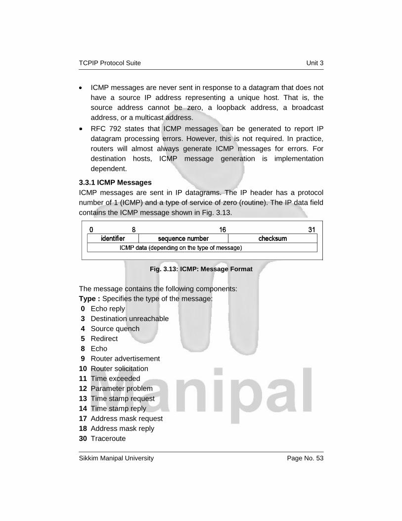
TCPIP Protocol Suite Unit 3
Sikkim Manipal University Page No. 53
ICMP messages are never sent in response to a datagram that does not
have a source IP address representing a unique host. That is, the
source address cannot be zero, a loopback address, a broadcast
address, or a multicast address.
RFC 792 states that ICMP messages can be generated to report IP
datagram processing errors. However, this is not required. In practice,
routers will almost always generate ICMP messages for errors. For
destination hosts, ICMP message generation is implementation
dependent.
3.3.1 ICMP Messages
ICMP messages are sent in IP datagrams. The IP header has a protocol
number of 1 (ICMP) and a type of service of zero (routine). The IP data field
contains the ICMP message shown in Fig. 3.13.
Fig. 3.13: ICMP: Message Format
The message contains the following components:
Type : Specifies the type of the message:
0 Echo reply
3 Destination unreachable
4 Source quench
5 Redirect
8 Echo
9 Router advertisement
10 Router solicitation
11 Time exceeded
12 Parameter problem
13 Time stamp request
14 Time stamp reply
17 Address mask request
18 Address mask reply
30 Traceroute

TCPIP Protocol Suite Unit 3
Sikkim Manipal University Page No. 54
37 Domain name request)
38 Domain name reply)
Code: Contains the error code for the datagram reported by this ICMP
message. The interpretation is dependent on the message type.
Checksum: Contains the checksum for the ICMP message starting. with
the ICMP Type field. If the checksum does not match the contents, the
datagram is discarded.
Data : Contains information for this ICMP message. Typically, it will contain
the portion of the original IP message for which this ICMP message was
generated. Each of the ICMP messages is described individually.
Echo (8) and Echo Reply (0): Echo is used to detect if another host is
active in the network. It is used by the Ping command. The sender initializes
the identifier, sequence number and data field. The datagram is then sent to
the destination host. The recipient changes the type to Echo Reply and
returns the datagram to the sender. See Fig. 3.14 for more details.
Fig. 3.14: Echo and Echo reply
Destination Unreachable (3): If this message is received from an
intermediate router, it means that the router regards the destination IP
address as unreachable. If this message is received from the destination
host, it means that either the protocol specified in the protocol number field
of the original datagram is not active or the specified port is inactive. See
Fig. 3.15 for more details.
Fig. 3.15: ICMP: Destination Unreachable

TCPIP Protocol Suite Unit 3
Sikkim Manipal University Page No. 55
The ICMP header code field contains one of the following values:
0 Network unreachable
1 Host unreachable
2 Protocol unreachable
3 Port unreachable
4 Fragmentation needed but the Do Not Fragment bit was set
5 Source route failed
6 Destination network unknown
7 Destination host unknown
8 Source host isolated (obsolete)
9 Destination network administratively prohibited
10 Destination host administratively prohibited
11 Network unreachable for this type of service
12 Host unreachable for this type of service
13 Communication administratively prohibited by filtering
14 Host precedence violation
15 Precedence cutoff in effect
Source Quench (4): If this message is received from an intermediate
router, it means that the router did not have the buffer space needed to
queue the datagram. If this message is received from the destination host, it
means that the incoming datagrams are arriving too quickly to be
processed. The ICMP header code field is always zero.
See Fig. 3.16 for more details.
Fig. 3.16: ICMP Source quench
Redirect (5): If this message is received from an intermediate router, it
means that the host should send future datagrams for the network to the
router whose IP address is specified in the ICMP message. This preferred
router will always be on the same subnet as the host that sent the datagram
and the router that returned the IP datagram. The router forwards the
datagram to its next hop destination. This message will not be sent if the IP

TCPIP Protocol Suite Unit 3
Sikkim Manipal University Page No. 56
datagram contains a source route. The ICMP header code field will have
one of the following values:
0 Network redirect
1 Host redirect
2 Network redirect for this type of service
3 Host redirect for this type of service
See Fig. 3.17 for more details.
Fig. 3.17: ICMP: Redirect
Router Advertisement (9) and Router Solicitation (10):
ICMP messages 9 and 10 are optional. They are described in RFC 1256,
which is elective. See Fig. 3.18 and Fig. 3.19 for details.
Fig. 3.18: ICMP: Router Advertisement

TCPIP Protocol Suite Unit 3
Sikkim Manipal University Page No. 57
Fig. 3.19: ICMP: Router Solicitation
Where:
Number: The number of entries in the message.
Entry length: The length of an entry in 32-bit units. This is 2 (32 bits for the
IP address and 32 bits for the preference value).
TTL: The number of seconds that an entry will be considered valid.
Router address: One of the sender's IP addresses.
Preference level : A signed 32-bit level indicating the preference to be
assigned to this address when selecting a default router. Each router on a
subnet is responsible for advertising its own preference level. Larger values
imply higher preference; smaller values imply lower. The default is zero,
which is in the middle of the possible range. A value of X'80000000' (-231)
indicates the router should never be used as a default router. The ICMP
header code field is zero for both of these messages. These two messages
are used if a host or a router supports the router discovery protocol. Routers
periodically advertise their IP addresses on those subnets where they are
configured to do so. Advertisements are made on the all-systems multicast
address (224.0.0.1) or the limited broadcast address (255.255.255.255).
The default behavior is to send advertisements every 10 minutes with a TTL
value of 1800 (30 minutes). Routers also reply to solicitation messages they
receive. They might reply directly to the soliciting host, or they might wait for
a short random interval and reply with a multicast. Hosts can send
solicitation messages. Solicitation messages are sent to the all-routers
multicast address (224.0.0.2) or the limited broadcast address
(255.255.255.255). Typically, three solicitation messages are sent at
3-second intervals. Alternatively, a host can wait for periodic
advertisements. Each time a host receives an advertisement with a higher
preference value, it updates its default router. The host also sets the TTL
timer for the new entry to match the value in the advertisement. When the
host receives a new advertisement for its current default router, it resets the

TCPIP Protocol Suite Unit 3
Sikkim Manipal University Page No. 58
TTL value to that in the new advertisement. This process also provides a
mechanism for routers to declare themselves unavailable. They send an
advertisement with a TTL value of zero.
Time Exceeded (11): If this message is received from an intermediate
router, it means that the time to live field of an IP datagram has expired. If
this message is received from the destination host, it means that the IP
fragment reassembly time to live timer has expired while the host is waiting
for a fragment of the datagram. The ICMP header code field can have the
one of the following values:
0 Transit TTL exceeded
1 Reassembly TTL exceeded
See Fig. 3.20 for more details.
Fig. 3.20: ICMP: Time exceeded
Parameter Problem (12):
This message indicates that a problem was encountered during processing
of the IP header parameters. The pointer field indicates the octet in the
original IP datagram where the problem was encountered. The ICMP
header code field can have the one of the following values:
0 Unspecified error
1 Required option missing
See Fig. 3.21 for more details.
Fig. 3.21: Parameter problem
Timestamp Request (13) and Timestamp Reply (14): These two
messages are for debugging and performance measurements. They are not
used for clock synchronization.

TCPIP Protocol Suite Unit 3
Sikkim Manipal University Page No. 59
The sender initializes the identifier and sequence number (which is used if
multiple time stamp requests are sent), sets the originate time stamp, and
sends the datagram to the recipient. The receiving host fills in the receive
and transmit time stamps, changes the type to time stamp reply, and returns
it to the original sender. The datagram has two time stamps if there is a
perceptible time difference between the receipt and transmit times. In
practice, most implementations perform the two (receipt and reply) in one
operation. This sets the two time stamps to the same value. Time stamps
are the number of milliseconds elapsed since midnight UT (GMT).See Fig
3.22 for more details.
Fig. 3.22: ICMP: Timestamp request and Timestamp reply
Address Mask Request (17) and Address Mask Reply (18): An address
mask request is used by a host to determine the subnet mask used on an
attached network. Most hosts are configured with their subnet mask or
masks. However some, such as diskless workstations, must obtain this
information from a server. A host uses RARP to obtain its IP address. To
obtain a subnet mask, the host broadcasts an address mask request. Any
host in the network that has been configured to send address mask replies
will fill in the subnet mask, convert the packet to an address mask reply, and
return it to the sender. The ICMP header code field is zero. See Fig. 3.23 for
more details.
Fig. 3.23: ICMP: Address mask request and reply
Self Assessment Questions
1. State True/False: ICMP messages are never sent in response to
datagrams with a broadcast or a multicast destination address.
2. A host uses RARP to obtain its _____________.

TCPIP Protocol Suite Unit 3
Sikkim Manipal University Page No. 60
3.4 Internet Group Management Protocol (IGMP) Similar to ICMP, the Internet Group Management Protocol (IGMP) is also an
integral part of IP. It allows hosts to participate in IP multicasts. IGMP further
provides routers with the capability to check if any hosts on a local subnet
are interested in a particular multicast.
3.5 Address Resolution Protocol (ARP) Address Resolution Protocol (ARP) is a network-specific standard protocol.
The address resolution protocol is responsible for converting the higher-
level protocol addresses (IP addresses) to physical network addresses. It is
described in RFC 826.
3.5.1 ARP Overview On a single physical network, individual hosts are known in the network by
their physical hardware address. Higher-level protocols address destination
hosts in the form of a symbolic address (IP address in this case). When
such a protocol wants to send a datagram to destination IP address w.x.y.z,
the device driver does not understand this address. Therefore, a module
(ARP) is provided that will translate the IP address to the physical address
of the destination host. It uses a lookup table (sometimes referred to as the
ARP cache) to perform this translation. When the address is not found in the
ARP cache, a broadcast is sent out in the network with a special format
called the ARP request. If one of the machines in the network recognizes its
own IP address in the request, it will send an ARP reply back to the
requesting host. The reply will contain the physical hardware address of the
host and source route information (if the packet has crossed bridges on its
path). Both this address and the source route information are stored in the
ARP cache of the requesting host. All subsequent datagrams to this
destination IP address can now be translated to a physical address, which is
used by the device driver to send out the datagram in the network. An
exception to the rule is the asynchronous transfer mode (ATM) technology,
where ARP cannot be implemented in the physical layer as described
previously. Therefore, every host, upon initialization, must register with an
ARP server in order to be able to resolve IP addresses to hardware
addresses ARP was designed to be used on networks that support
hardware broadcast.
3.5.2 ARP Detailed Concept
ARP is used on IEEE 802 networks as well as on the older DIX Ethernet
networks to map IP addresses to physical hardware. To do this, it is closely
related to the device driver for that network. In fact, the ARP specifications

TCPIP Protocol Suite Unit 3
Sikkim Manipal University Page No. 61
in RFC 826 only describe its functionality, not its implementation. The
implementation depends to a large extent on the device driver for a network
type and they are usually coded together in the adapter microcode.
ARP Packet Generation
If an application wants to send data to a certain IP destination address, the
IP routing mechanism first determines the IP address of the next hop of the
packet (it can be the destination host itself, or a router) and the hardware
device on which it should be sent. If it is an IEEE 802.3/4/5 network, the
ARP module must be consulted to map the <protocol type, target protocol
address> to a physical address.
The ARP module tries to find the address in this ARP cache. If it finds the
matching pair, it gives the corresponding 48-bit physical address back to the
caller (the device driver), which then transmits the packet. If it does not find
the pair in its table, it discards the packet (the assumption is that a higher-
level protocol will retransmit) and generates a network broadcast of an ARP
request.
See Fig. 3.24 for more details.
Fig. 3.24: ARP: Request/reply packet
Where:
Hardware address space: Specifies the type of hardware; examples are
Ethernet or Packet Radio Net.
Protocol address space: Specifies the type of protocol, same as the
EtherType field in the IEEE 802 header (IP or ARP).

TCPIP Protocol Suite Unit 3
Sikkim Manipal University Page No. 62
Hardware address length: Specifies the length (in bytes) of the hardware
addresses in this packet. For IEEE 802.3 and IEEE 802.5, this is 6.
Protocol address length: Specifies the length (in bytes) of the protocol
addresses in this packet. For IP, this is 4.
Operation code: Specifies whether this is an ARP request (1) or reply (2).
Source/target hardware address: Contains the physical network hardware
addresses. For IEEE 802.3, these are 48-bit addresses.
Source/target protocol address: Contains the protocol addresses. For
TCP/IP, these are the 32-bit IP addresses. For the ARP request packet, the
target hardware address is the only undefined field in the packet.
ARP Packet Reception
When a host receives an ARP packet (either a broadcast request or a point-
to-point reply), the receiving device driver passes the packet to the ARP
module, which treats it as shown in Fig. 3.25.
Fig. 3.25: ARP: Packet reception

TCPIP Protocol Suite Unit 3
Sikkim Manipal University Page No. 63
The requesting host will receive this ARP reply, and will follow the same
algorithm to treat it. As a result of this, the triplet <protocol type, protocol
address, hardware address> for the desired host will be added to its lookup
table (ARP cache). The next time a higher-level protocol wants to send a
packet to that host, the ARP module will find the target hardware address
and the packet will be sent to that host. Note that because the original ARP
request was a broadcast in the network, all hosts on that network will have
updated the sender's hardware address in their table (only if it was already
in the table).
Self Assessment Questions
1. ARP module will translate the __________ to the _______ of the
destination host.
3.6 Reverse Address Resolution Protocol (RARP) Reverse Address Resolution Protocol (RARP) is a network-specific standard
protocol. It is described in RFC 903. Some network hosts, such as diskless
workstations, do not know their own IP address when they are booted. To
determine their own IP address, they use a mechanism similar to ARP, but
now the hardware address of the host is the known parameter and the IP
address the queried parameter. It differs more fundamentally from ARP in
the fact that a RARP server must exist in the network that maintains that a
database of mappings from hardware address to protocol address must be
preconfigured.
3.6.1 RARP Concept
The reverse address resolution is performed the same way as the ARP
address resolution. The same packet format is used as for ARP.
An exception is the operation code field that now takes the following values:
3 For the RARP request
4 For the RARP reply
And of course, the physical header of the frame will now indicate RARP as
the higher-level protocol (8035 hex) instead of ARP (0806 hex) or IP (0800
hex) in the EtherType field.
Some differences arise from the concept of RARP itself:
1. ARP only assumes that every host knows the mapping between its own
hardware address and protocol address. RARP requires one or more

TCPIP Protocol Suite Unit 3
Sikkim Manipal University Page No. 64
server hosts in the network to maintain a database of mappings between
hardware addresses and protocol addresses so that they will be able to
reply to requests from client hosts.
2. Due to the size this database can take, part of the server function is
usually implemented outside the adapter's microcode, with optionally a
small cache in the microcode. The microcode part is then only
responsible for reception and transmission of the RARP frames, the
RARP mapping itself being taken care of by server software running as
a normal process on the host machine.
3. The nature of this database also requires some software to create and
update the database manually.
4. If there are multiple RARP servers in the network, the RARP requester
only uses the first RARP reply received on its broadcast RARP request
and discards the others.
Self Assessment Questions
1. State True/False: RARP requires one or more server hosts in the
network to maintain a database of mappings between hardware
addresses and protocol addresses so that they will be able to reply to
requests from client hosts.
3.7 Bootstrap Protocol (BOOTP) The Bootstrap Protocol (BOOTP) enables a client workstation to initialize
with a minimal IP stack and request its IP address, a gateway address, and
the address of a name server from a BOOTP server. If BOOTP is to be used
in your network, the server and client are usually on the same physical LAN
segment. BOOTP can only be used across bridged segments when source-
routing bridges are being used, or across subnets, if you have a router
capable of BOOTP forwarding.
BOOTP is a draft standard protocol. Its status is recommended. The
BOOTP specifications are in RFC 951, which has been updated by
RFC1542 and RFC 2132.
The BOOTP protocol was originally developed as a mechanism to enable
diskless hosts to be remotely booted over a network as workstations,
routers, terminal concentrators, and so on. It allows a minimum IP protocol
stack with no configuration information to obtain enough information to begin

TCPIP Protocol Suite Unit 3
Sikkim Manipal University Page No. 65
the process of downloading the necessary boot code. Although still widely
used for this purpose by diskless hosts, BOOTP is also commonly used
solely as a mechanism to deliver configuration information to a client that
has not been manually configured.
The BOOTP process involves the following steps:
1. The client determines its own hardware address; this is normally in a
ROM on the hardware.
2. A BOOTP client sends its hardware address in a UDP datagram to the
server.
If the client knows its IP address or the address of the server, it should
use them, but in general, BOOTP clients have no IP configuration data
at all. If the client does not know its own IP address, it uses 0.0.0.0. If
the client does not know the server's IP address, it uses the limited
broadcast address (255.255.255.255). The UDP port number is 67.
3. The server receives the datagram and looks up the hardware address of
the client in its configuration file, which contains the client's IP address.
The server fills in the remaining fields in the UDP datagram and returns
it to the client using UDP port 68.
4. When it receives the reply, the BOOTP client will record its own IP
address (allowing it to respond to ARP requests) and begin the
bootstrap process.
Figure 3.26 gives an overview of the BOOTP message format.
Fig. 3.26: BOOTP message format

TCPIP Protocol Suite Unit 3
Sikkim Manipal University Page No. 66
Where:
Code: Indicates a request or a reply:
1 Request
2 Reply
H/W type: The type of hardware, for example:
1 Ethernet
6 IEEE 802 Networks
Length: Hardware address length in bytes. Ethernet and token ring both
use 6, for example.
Hops: The client sets this to 0. It is incremented by a router that relays the
request to another server and is used to identify loops. RFC 951 suggests
that a value of 3 indicates a loop.
Transaction ID: A random number used to match this boot request with the
response it generates.
Seconds: Set by the client. It is the elapsed time in seconds since the client
started its boot process.
Flags Field: The most significant bit of the flags field is used as a broadcast
flag. All other bits must be set to zero; they are reserved for future use.
Normally, BOOTP servers attempt to deliver BOOTREPLY messages
directly to a client using unicast delivery. The destination address in the IP
header is set to the BOOTP your IP address and the MAC address is set to
the BOOTP client hardware address. If a host is unable to receive a unicast
IP datagram until it knows its IP address, this broadcast bit must be set to
indicate to the server that the BOOTREPLY must be sent as an IP and MAC
broadcast. Otherwise, this bit must be set to zero.
Client IP Address: Set by the client, either to its known IP address or
0.0.0.0.
Your IP Address: Set by the server if the client IP address field was
0.0.0.0.
Server IP Address: Set by the server.
Router IP Address: This is the address of a BOOTP relay agent, not a
general IP router to be used by the client. It is set by the forwarding agent
when BOOTP forwarding is used.

TCPIP Protocol Suite Unit 3
Sikkim Manipal University Page No. 67
Client Hardware Address
Set by the client and used by the server to identify which registered client is
booting.
Server Host Name: Optional server host name terminated by X'00'.
Boot File Name: The client either leaves this null or specifies a generic
name, such as router indicating the type of boot file to be used. The server
returns the fully qualified file name of a boot file suitable for the client. The
value is terminated by X'00'.
Vendor-Specific Area: Optional vendor-specific area. Clients should
always fill the first four bytes with a “magic cookie.” If a vendor-specific
magic cookie is not used, the client should use 99.130.83.99 followed by an
end tag (255) and set the remaining bytes to zero. The vendor-specific area
can also contain BOOTP Vendor extensions. These are options that can be
passed to the client at boot time along with its IP address. For example, the
client can also receive the address of a default router, the address of a
domain name server, and a subnet mask. BOOTP shares the same options
as DHCP, with the exception of several DHCP-specific options. See RFC
2132 for full details. After the BOOTP client has processed the reply, it can
proceed with the transfer of the boot file and execute the full boot process.
See RFC 906 for the specification of how this is done with TFTP. In the case
of a diskless host, the full boot process will normally replace the minimal IP
protocol stack, loaded from ROM, and used by BOOTP and TFTP, with a
normal IP protocol stack transferred as part of the boot file and containing
the correct customization for the client.
3.7.1 BOOTP Forwarding
The BOOTP client uses the limited broadcast address for BOOTP requests,
which requires the BOOTP server to be on the same subnet as the client.
BOOTP forwarding is a mechanism for routers to forward BOOTP requests
across subnets. It is a configuration option available on most routers. The
router configured to forward BOOTP requests is known as a BOOTP relay
agent. A router will normally discard any datagrams containing illegal source
addresses, such as 0.0.0.0, which is used by a BOOTP client. A router will
also generally discard datagrams with the limited broadcast destination
address. However, a BOOTP relay agent will accept such datagrams from
BOOTP clients on port 67.

TCPIP Protocol Suite Unit 3
Sikkim Manipal University Page No. 68
The process carried out by a BOOTP relay agent on receiving a
BOOTPREQUEST is as follows:
1. When the BOOTP relay agent receives a BOOTPREQUEST, it first
checks the hops field to check the number of hops already completed in
order to decide whether to forward the request. The threshold for the
allowable number of hops is normally configurable.
2. If the relay agent decides to relay the request, it checks the contents of
the router IP address field. If this field is zero, it fills this field with the IP
address of the interface on which the BOOTPREQUEST was received. If
this field already has an IP address of another relay agent, it is not
touched.
3. The value of the hops field is incremented.
4. The relay agent then forwards the BOOTPREQUEST to one or more
BOOTP servers. The address of the BOOTP server or servers is
preconfigured at the relay agent. The BOOTPREQUEST is normally
forwarded as a unicast frame, although some implementations use
broadcast forwarding.
5. When the BOOTP server receives the BOOTPREQUEST with the non-
zero router IP address field, it sends an IP unicast BOOTREPLY to the
BOOTP relay agent at the address in this field on port 67.
6. When the BOOTP relay agent receives the BOOTREPLY, the H/W type,
length, and client hardware address fields in the message supply
sufficient link layer information to return the reply to the client. The relay
agent checks the broadcast flag. If this flag is set, the agent forwards the
BOOTPREPLY to the client as a broadcast. If the broadcast flag is not
set, the relay agent sends a reply as a unicast to the address specified
in your IP address. When a router is configured as a BOOTP relay
agent, the BOOTP forwarding task is considerably different from the task
of switching datagrams between subnets normally carried out by a
router. Forwarding of BOOTP messages can be considered to be
receiving BOOTP messages as a final destination, and then generating
new BOOTP messages to be forwarded to another destination.
TCPIP Protocol Suite Unit 3
Sikkim Manipal University Page No. 69
Self Assessment Questions
1. The BOOTP protocol was originally developed as a mechanism to
enable _________ hosts to be remotely booted over a network as
workstations, routers, terminal concentrators.
2. BOOTP servers attempt to deliver BOOTREPLY messages directly to a
client using ____________ delivery.
3.8 Dynamic Host Configuration Protocol (DHCP) The Dynamic Host Configuration Protocol (DHCP) provides a framework for
passing configuration information to hosts on a TCP/IP network. DHCP is
based on the BOOTP protocol, adding the capability of automatic allocation
of reusable network addresses and additional configuration options. DHCP
messages use UDP port 67, the BOOTP server's well-known port and UDP
port 68, the BOOTP client's well-known port. DHCP participants can
interoperate with BOOTP participants. DHCP consists of two components:
1. A protocol that delivers host-specific configuration parameters from a
DHCP server to a host.
2. A mechanism for the allocation of temporary or permanent network
addresses to hosts.
IP requires the setting of many parameters within the protocol
implementation software. Because IP can be used on many dissimilar kinds
of network hardware, values for those parameters cannot be guessed at or
assumed to have correct defaults. The use of a distributed address
allocation scheme based on a polling/defense mechanism, for discovery of
network addresses already in use, cannot guarantee unique network
addresses because hosts might not always be able to defend their network
addresses.
DHCP supports three mechanisms for IP address allocation:
1. Automatic Allocation: DHCP assigns a permanent IP address to the
host.
2. Dynamic Allocation: DHCP assigns an IP address for a limited period
of time. Such a network address is called a lease. This is the only
mechanism that allows automatic reuse of addresses that are no longer
needed by the host to which it was assigned.

TCPIP Protocol Suite Unit 3
Sikkim Manipal University Page No. 70
3. Manual Allocation: The host's address is assigned by a network
administrator.
3.8.1 The DHCP Message Format
The format of a DHCP message is shown in Fig. 3.27.
Fig. 3.27: DHCP message format
Where:
Code: Indicates a request or a reply:
1 Request
2 Reply
HWtype: The type of hardware, for example:
1 Ethernet
6 IEEE 802 Networks
Refer to STD 2 – Assigned Internet Numbers for a complete list.
Length: Hardware address length in bytes.

TCPIP Protocol Suite Unit 3
Sikkim Manipal University Page No. 71
Hops: The client sets this to 0. It is incremented by a router that relays the
request to another server and is used to identify loops. RFC 951 suggests
that a value of 3 indicates a loop.
Transaction ID: A random number used to match this boot request with the
response it generates.
Seconds: Set by the client. It is the elapsed time in seconds since the client
started its boot process.
Flags field: The most significant bit of the flags field is used as a broadcast
flag. All other bits must be set to zero, and are reserved for future use.
Normally, DHCP servers attempt to deliver DHCP messages directly to a
client using unicast delivery. The destination address in the IP header is set
to the DHCP your IP address and the MAC address is set to the DHCP
client hardware address. If a host is unable to receive a unicast IP datagram
until it knows its IP address, this broadcast bit must be set to indicate to the
server that the DHCP reply must be sent as an IP and MAC broadcast.
Otherwise, this bit must be set to zero.
Client IP Address: Set by the client. Either its known IP address, or 0.0.0.0.
Your IP Address: Set by the server if the client IP address field was
0.0.0.0.
Server IP Address: Set by the server.
Router IP Address: This is the address of a BOOTP relay agent, not a
general IP router to be used by the client. It is set by the forwarding agent
when BOOTP forwarding is used
Client Hardware Address: Set by the client. DHCP defines a client
identifier option that is used for client identification. If this option is not used,
the client is identified by its MAC address.
Server Host Name: Optional server host name terminated by X'00'.
Boot File Name: The client either leaves this null or specifies a generic
name, such as router, indicating the type of boot file to be used. In a
DHCPDISCOVER request, this is set to null. The server returns a fully
qualified directory path name in a DHCPOFFER request. The value is
terminated by X'00'.

TCPIP Protocol Suite Unit 3
Sikkim Manipal University Page No. 72
Options: The first four bytes of the options field of the DHCP message
contain the magic cookie (99.130.83.99). The remainder of the options field
consists of tagged parameters that are called options.
3.8.2 DHCP Message Types
DHCP messages fall into one of the following categories:
1. DHCPDISCOVER: Broadcast by a client to find available DHCP servers.
2. DHCPOFFER: Response from a server to a DHCPDISCOVER and
offering IP address and other parameters.
3. DHCPREQUEST: Message from a client to servers that does one of the
following:
Requests the parameters offered by one of the servers and declines
all other offers.
Verifies a previously allocated address after a system or network
change (a reboot for example).
Requests the extension of a lease on a particular address.
4. DHCPACK: Acknowledgement from server to client with parameters,
including IP address.
5. DHCPNACK: Negative acknowledgement from server to client,
indicating that the client's lease has expired or that a requested IP
address is incorrect.
6. DHCPDECLINE: Message from client to server indicating that the
offered address is already in use.
7. DHCPRELEASE: Message from client to server cancelling remainder of
a lease and relinquishing network address.
8. DHCPINFORM: Message from a client that already has an IP address
(manually configured, for example), requesting further configuration
parameters from the DHCP server.
3.8.3 Allocating a New Network Address
This section describes the client/server interaction if the client does not
know its network address. Assume that the DHCP server has a block of
network addresses from which it can satisfy requests for new addresses.
Each server also maintains a database of allocated addresses and leases in
permanent local storage.

TCPIP Protocol Suite Unit 3
Sikkim Manipal University Page No. 73
The DHCP client/server interaction steps are illustrated in Fig. 3.28.
Fig. 3.28: DHCP client and DHCP server interaction
The following procedure describes the DHCP client/server interaction steps
illustrated in Fig. 3.28:
1. The client broadcasts a DHCPDISCOVER message on its local physical
subnet. At this point, the client is in the INIT state. The
DHCPDISCOVER message might include some options such as
network address suggestion or lease duration.
2. Each server responds with a DHCPOFFER message that includes an
available network address (your IP address) and other configuration
options. The servers record the address as offered to the client to
prevent the same address being offered to other clients in the event of
further DHCPDISCOVER messages being received before the first client
has completed its configuration.
3. The client receives one or more DHCPOFFER messages from one or
more servers. The client chooses one based on the configuration

TCPIP Protocol Suite Unit 3
Sikkim Manipal University Page No. 74
parameters offered and broadcasts a DHCPREQUEST message that
includes the server identifier option to indicate which message it has
selected and the requested IP address option taken from your IP
address in the selected offer.
4. In the event that no offers are received, if the client has knowledge of a
previous network address, the client can reuse that address if its lease is
still valid until the lease expires.
5. The servers receive the DHCPREQUEST broadcast from the client.
Those servers not selected by the DHCPREQUEST message use the
message as notification that the client has declined that server's offer.
The server selected in the DHCPREQUEST message commits the
binding for the client to persistent storage and responds with a
DHCPACK message containing the configuration parameters for the
requesting client. The combination of client hardware and assigned
network address constitute a unique identifier for the client's lease and
are used by both the client and server to identify a lease referred to in
any DHCP messages. your IP address field in the DHCPACK messages
is filled in with the selected network address.
6. The client receives the DHCPACK message with configuration
parameters. The client performs a final check on the parameters, for
example, with ARP for allocated network address, and notes the
duration of the lease and the lease identification cookie specified in the
DHCPACK message. At this point, the client is configured.
7. If the client detects a problem with the parameters in the DHCPACK
message (the address is already in use in the network, for example), the
client sends a DHCPDECLINE message to the server and restarts the
configuration process. The client should wait a minimum of ten seconds
before restarting the configuration process to avoid excessive network
traffic in case of looping. On receipt of a DHCPDECLINE, the server
must mark the offered address as unavailable (and possibly inform the
system administrator that there is a configuration problem).
8. If the client receives a DHCPNAK message, the client restarts the
configuration process.
9. The client may choose to relinquish its lease on a network address by
sending a DHCPRELEASE message to the server. The client identifies

TCPIP Protocol Suite Unit 3
Sikkim Manipal University Page No. 75
the lease to be released by including its network address and its
hardware address.
3.8.4 DHCP Lease Renewal Process
This section describes the interaction between DHCP servers and clients
that have already been configured and the process that ensures lease
expiration and renewal.
The process involves the following steps:
1. When a server sends the DHCPACK to a client with IP address and
configuration parameters, it also registers the start of the lease time for
that address. This lease time is passed to the client as one of the
options in the DHCPACK message, together with two timer values, T1
and T2. The client is rightfully entitled to use the given address for the
duration of the lease time. On applying the received configuration, the
client also starts the timers T1 and T2. At this time, the client is in the
BOUND state. Times T1 and T2 are options configurable by the server,
but T1 must be less than T2, and T2 must be less than the lease time.
According to RFC 2132, T1 defaults to (0.5 * lease time) and T2 defaults
to (0.875 * lease time).
2. When timer T1 expires, the client will send a DHCPREQUEST (unicast)
to the server that offered the address, asking to extend the lease for the
given configuration. The client is now in the RENEWING state. The
server usually responds with a DHCPACK message indicating the new
lease time, and timers T1 and T2 are reset at the client accordingly. The
server also resets its record of the lease time. In normal circumstances,
an active client continually renews its lease in this way indefinitely,
without the lease ever expiring.
3. If no DHCPACK is received until timer T2 expires, the client enters the
REBINDING state. It now broadcasts a DHCPREQUEST message to
extend its lease. This request can be confirmed by a DHCPACK
message from any DHCP server in the network.
4. If the client does not receive a DHCPACK message after its lease has
expired, it has to stop using its current TCP/IP configuration. The client
can then return to the INIT state, issuing a DHCPDISCOVER broadcast
to try and obtain any valid address.
TCPIP Protocol Suite Unit 3
Sikkim Manipal University Page No. 76
3.8.5 Reusing a Previously Allocated Network Address
If the client remembers and wants to reuse a previously allocated network
address, the following steps are carried out:
1. The client broadcasts a DHCPREQUEST message on its local subnet.
The DHCPREQUEST message includes the client's network address.
2. A server with knowledge of the client's configuration parameters
responds with a DHCPACK message to the client (provided the lease is
still current), renewing the lease at the same time.
3. If the client's lease has expired, the server with knowledge of the client
responds with DHCPNACK.
4. The client receives the DHCPACK message with configuration
parameters. The client performs a final check on the parameters and
notes the duration of the lease and the lease identification cookie
specified in the DHCPACK message. At this point, the client is
configured and its T1 and T2 timers are reset.
5. If the client detects a problem with the parameters in the DHCPACK
message, the client sends a DHCPDECLINE message to the server and
restarts the configuration process by requesting a new network address.
If the client receives a DHCPNAK message, it cannot reuse its
remembered network address. It must instead request a new address by
restarting the configuration process allocating a new network address.
Self Assessment Questions
1. DHCP assigns an IP address for a limited period of time. Such a network
address is called a ______________.
2. ____________ is message from client to server indicating that the
offered address is already in use.
3.9 Summary IP is an unreliable, best-effort, and connectionless packet delivery protocol.
IP datagram consists of an IP header and data relevant to higher-level
protocols. IP implements a process to fragment datagrams exceeding the
MTU. When a router or a destination host must inform the source host about
errors in datagram processing, it uses the Internet Control Message
Protocol (ICMP). IGMP allows hosts to participate in IP multicasts. ARP will

TCPIP Protocol Suite Unit 3
Sikkim Manipal University Page No. 77
translate the IP address to the physical address of the destination host.
DHCP provides a framework for passing configuration information to hosts
on a TCP/IP network.
3.10 Terminal Questions
1. The ____________ command can be used on some IP hosts to list the
details of fragmentation.
2. An un-fragmented datagram has an _____________ fragmentation
information field.
3. State True/False: ICMP is used to report errors, not to make IP reliable.
4. State True/False: BOOTP client sends its hardware address in a TCP
datagram to the server.
3.11 Answers for Self Assessment Questions 3.2 1) 65535
2) TTL
3) 4-bits, 16-bits
4) loopback
3.3 1) True
2) IP Address
3.5 1) IP Address, physical address
3.6 1) True
3.7 1) diskless
2) unicast
3.8 1) lease
2) DHCPDECLINE
3.12 Answers for Terminal Questions 1. netstat
2. all-zero
3. True
4. False

TCPIP Protocol Suite Unit 3
Sikkim Manipal University Page No. 78
3.13 Exercises
1. What is fragmentation? Explain its significance.
2. Discuss various OPTIONS used by IP.
3. Clearly differentiate between ARP and RARP.
4. Discuss the process carried out by a BOOTP relay agent on receiving a
BOOTPREQUEST.
5. Explain the steps involved in DHCP client/server interaction.

TCPIP Protocol Suite Unit 4
Sikkim Manipal University Page No. 79
Unit 4 Transport Protocols
Structure
4.1 Introduction
4.2 Ports and Sockets
Ports
Sockets
4.3 User Datagram Protocol (UDP)
UDP Datagram Format
UDP Application Programming Interface
4.4 Transmission Control Protocol (TCP)
TCP Concepts
TCP Congestion Control Algorithms
4.5 Summary
4.6 Terminal Questions
4.7 Answers for Self Assessment Questions
4.8 Answers for Terminal Questions
4.9 Exercises
4.1 Introduction
This chapter provides an overview of the most important and commonly
used protocols of the TCP/IP transport layer. These include: User Datagram
Protocol (UDP) and Transmission Control Protocol (TCP). By building on the
functionality provided by the Internet Protocol (IP), the transport protocols
deliver data to applications executing in the internet. This is done by making
use of ports. The transport protocols can provide additional functionality
such as congestion control, reliable data delivery, duplicate data
suppression and flow control as is done by TCP.
Objectives:
After the completion of this chapter you will be able to understand:
TCP and UDP header format
TCP Congestion Control Mechanism
4.2 Ports and Sockets
This section introduces the concepts of the port and socket, which are
needed to determine which local process at a given host actually

TCPIP Protocol Suite Unit 4
Sikkim Manipal University Page No. 80
communicates with which process, at which remote host, using which
protocol. If this sounds confusing, consider the following points:
An application process is assigned a process identifier number (process
ID), which is likely to be different each time that process is started.
Process IDs differ between operating system platforms, thus they are
not uniform.
A server process can have multiple connections to multiple clients at a
time, thus simple connection identifiers are not unique.
The concept of ports and sockets provide a way to uniformly and uniquely
identify connections and the programs and hosts that are engaged in them,
irrespective of specific process IDs.
4.2.1 Ports
Each process that wants to communicate with another process identifies
itself to the TCP/IP protocol suite by one or more ports. A port is a 16-bit
number used by the host-to-host protocol to identify to which higher-level
protocol or application program (process) it must deliver incoming
messages. There are two types of ports:
1. Well-Known: Well-known ports belong to standard servers, for example,
Telnet uses port 23. Well-known port numbers range between 1 and
1023 (prior to 1992, the range between 256 and 1023 was used for
UNIX-specific servers). Well-known port numbers are typically odd,
because early systems using the port concept required an odd/even pair
of ports for duplex operations. Most servers require only a single port.
Exceptions are the BOOTP server, which uses two: 67 and 68 and the
FTP server, which uses two: 20 and 21. The well-known ports are
controlled and assigned by the Internet Assigned Number Authority
(IANA) and on most systems can only be used by system processes or
by programs executed by privileged users. Well-known ports allow
clients to find servers without configuration information. The well-known
port numbers are defined in STD 2 – Assigned Internet Numbers.
2. Ephemeral: Some clients do not need well-known port numbers
because they initiate communication with servers, and the port number
they are using is contained in the UDP/TCP datagrams sent to the
server. Each client process is allocated a port number, for as long as it
needs, by the host on which it is running. Ephemeral port numbers have

TCPIP Protocol Suite Unit 4
Sikkim Manipal University Page No. 81
values greater than 1023, normally in the range of 1024 to 65535.
Ephemeral ports are not controlled by IANA and can be used by
ordinary user-developed programs on most systems. Confusion, due to
two different applications trying to use the same port numbers on one
host, is avoided by writing those applications to request an available port
from TCP/IP. Because this port number is dynamically assigned, it can
differ from one invocation of an application to the next. UDP, TCP and
ISO TP-4 all use the same port principle. To the best possible extent,
the same port numbers are used for the same services on top of UDP,
TCP and ISO TP-4.
4.2.2 Sockets
The socket interface is one of several application programming interfaces to
the communication protocols. Designed to be a generic communication
programming interface, socket APIs were first introduced by Berkeley
Software Distribution (BSD). Although it has not been standardized,
Berkeley socket API has become a de facto industry standard abstraction
for network TCP/IP socket implementation. Consider the following
terminologies:
A socket is a special type of file handle, which is used by a process to
request network services from the operating system.
A socket address is the triple: <protocol, local-address, local port>
For example, in the TCP/IP (version 4) suite:
<tcp, 192.168.14.234, 8080>
A conversation is the communication link between two processes.
An association is the 5-tuple that completely specifies the two processes
that comprise a connection:
<protocol, local-address, local-port, foreign-address, foreign-port>
In the TCP/IP (version 4) suite, the following could be a valid
association:
<tcp, 192.168.14.234, 1500, 192.168.44, 22>
A half-association is either one of the following, which each specify half
of a connection:
<protocol, local-address, local-process>
Or:
<protocol, foreign-address, foreign-process>

TCPIP Protocol Suite Unit 4
Sikkim Manipal University Page No. 82
The half-association is also called a socket or a transport address. That is, a
socket is an endpoint for communication that can be named and addressed
in a network. Two processes communicate through TCP sockets. The
socket model provides a process with a full-duplex byte stream connection
to another process. The application need not concern itself with the
management of this stream; these facilities are provided by TCP. TCP uses
the same port principle as UDP to provide multiplexing. Like UDP, TCP uses
well-known and ephemeral ports. Each side of a TCP connection has a
socket that can be identified by the triple <TCP, IP address, port number>. If
two processes are communicating over TCP, they have a logical connection
that is uniquely identifiable by the two sockets involved, that is, by the
combination <TCP, local IP address, local port, remote IP address, remote
port>. Server processes are able to manage multiple conversations through
a single port.
Self Assessment Questions
1. State True/False: Process IDs differ between operating system
platforms, thus they are not uniform.
2. Ephemeral port numbers have values greater than ____________ .
4.3 User Datagram Protocol (UDP)
UDP is a standard protocol with STD number 6. UDP is described by RFC
768 – User Datagram Protocol. Its status is standard and almost every
TCP/IP implementation intended for small data units transfer or those which
can afford to lose a little amount of data (such as multimedia streaming) will
include UDP. UDP is basically an application interface to IP. It adds no
reliability, flow-control or error recovery to IP. It simply serves as a
multiplexer/de-multiplexer for sending and receiving datagrams, using ports
to direct the datagrams, as shown in

TCPIP Protocol Suite Unit 4
Sikkim Manipal University Page No. 83
Fig. 4.1. for a more detailed discussion of ports.
Fig. 4.1: UDP: De-Multiplexing based on ports
UDP provides a mechanism for one application to send a datagram to
another. The UDP layer can be regarded as being extremely thin and is,
consequently, very efficient, but it requires the application to take
responsibility for error recovery and so on. Applications sending datagrams
to a host need to identify a target that is more specific than the IP address,
because datagrams are normally directed to certain processes and not to
the system as a whole. UDP provides this by using ports.
4.3.1 UDP Datagram Format
Each UDP datagram is sent within a single IP datagram. Although, the IP
datagram might be fragmented during transmission, the receiving IP
implementation will reassemble it before presenting it to the UDP layer. All
IP implementations are required to accept datagrams of 576 bytes, which
means that, allowing for maximum-size IP header of 60 bytes, a UDP
datagram of 516 bytes is acceptable to all implementations. Many
implementations will accept larger datagrams, but this is not guaranteed.
The UDP datagram has an 8-byte header, as described in Fig. 4.2.
Fig. 4.2: UDP: Datagram Format

TCPIP Protocol Suite Unit 4
Sikkim Manipal University Page No. 84
Where:
Source Port: Indicates the port of the sending process. It is the port to
which replies are addressed.
Destination Port: Specifies the port of the destination process on the
destination host.
Length: The length (in bytes) of this user datagram, including the header.
Checksum: An optional 16-bit one's complement of the one's complement
sum of a pseudo-IP header, the UDP header, and the UDP data. In Fig. 4.3,
we see a pseudo-IP header. It contains the source and destination IP
addresses, the protocol, and the UDP length.
Fig. 4.3: UDP: Pseudo-IP Header
The pseudo-IP header effectively extends the checksum to include the
original (unfragmented) IP datagram.
4.3.2 UDP Application Programming Interface
The application interface offered by UDP is described in RFC 768. It
provides for:
The creation of new receive ports.
The receive operation that returns the data bytes and an indication of
source port and source IP address.
The send operation that has, as parameters, the data, source, and
destination ports and addresses.
The way this interface is implemented is left to the discretion of each
vendor. Be aware that UDP and IP do not provide guaranteed delivery, flow-
control, or error recovery, so these must be provided by the application.
Self Assessment Questions
1. The UDP datagram has an ____________ byte header.
2. State True/False: UDP provides flow control and congestion control.

TCPIP Protocol Suite Unit 4
Sikkim Manipal University Page No. 85
4.4 Transmission Control Protocol (TCP)
TCP is a standard protocol with STD number 7. TCP is described by RFC
793 – Transmission Control Protocol. Its status is standard, and in practice,
every TCP/IP implementation that is not used exclusively for routing will
include TCP. TCP provides considerably more facilities for applications than
UDP. Specifically, this includes error recovery, flow control, and reliability.
TCP is a connection-oriented protocol, unlike UDP, which is connectionless.
Most of the user application protocols, such as Telnet and FTP, use TCP.
The two processes communicate with each other over a TCP connection
(Inter-Process Communication, or IPC), as shown in Fig. 4.4. In the figure,
processes 1 and 2 communicate over a TCP connection carried by IP
datagrams.
Fig. 4.4: TCP: Connection between Processes
4.4.1 TCP Concepts
As noted earlier, the primary purpose of TCP is to provide a reliable logical
circuit or connection service between pairs of processes. It does not assume
reliability from the lower-level protocols (such as IP), so TCP must
guarantee this itself. TCP can be characterized by the following facilities it
provides for the applications using it:

TCPIP Protocol Suite Unit 4
Sikkim Manipal University Page No. 86
1. Stream Data Transfer: From the application's viewpoint, TCP transfers
a contiguous stream of bytes through the network. The application does
not have to bother with chopping the data into basic blocks or
datagrams. TCP does this by grouping the bytes into TCP segments,
which are passed to the IP layer for transmission to the destination.
Also, TCP itself decides how to segment the data, and it can forward the
data at its own convenience. Sometimes, an application needs to be
sure that all the data passed to TCP has actually been transmitted to the
destination. For that reason, a push function is defined. It will push all
remaining TCP segments still in storage to the destination host. The
normal close connection function also pushes the data to the
destination.
2. Reliability: TCP assigns a sequence number to each byte transmitted,
and expects a positive acknowledgment (ACK) from the receiving TCP
layer. If the ACK is not received within a timeout interval, the data is
retransmitted. Because the data is transmitted in blocks (TCP
segments), only the sequence number of the first data byte in the
segment is sent to the destination host. The receiving TCP uses the
sequence numbers to rearrange the segments when they arrive out of
order, and to eliminate duplicate segments.
3. Flow Control: The receiving TCP, when sending an ACK back to the
sender, also indicates to the sender the number of bytes it can receive
(beyond the last received TCP segment) without causing overrun and
overflow in its internal buffers. This is sent in the ACK in the form of the
highest sequence number it can receive without problems. This
mechanism is also referred to as a window-mechanism, and we discuss
it in more detail later in this chapter.
4. Multiplexing: Achieved through the use of ports, just as with UDP.
5. Logical Connections: The reliability and flow control mechanisms
described here require that TCP initializes and maintains certain status
information for each data stream. The combination of this status,
including sockets, sequence numbers, and window sizes, is called a
logical connection. Each connection is uniquely identified by the pair of
sockets used by the sending and receiving processes.
6. Full Duplex: TCP provides for concurrent data streams in both
directions.

TCPIP Protocol Suite Unit 4
Sikkim Manipal University Page No. 87
The Window Principle
A simple transport protocol might use the following principle: send a packet
and then wait for an acknowledgment from the receiver before sending the
next packet. If the ACK is not received within a certain amount of time,
retransmit the packet. See Fig. 4.5 for more details.
Fig. 4.5: TCP: The Window Principle
Although this mechanism ensures reliability, it only uses a part of the
available network bandwidth. Now, consider a protocol where the sender
groups its packets to be transmitted, as in Fig. 4.6, and uses the following
rules:
1. The sender can send all packets within the window without receiving an
ACK, but must start a timeout timer for each of them.
2. The receiver must acknowledge each packet received, indicating the
sequence number of the last well-received packet.
3. The sender slides the window on each ACK received.
Fig. 4.6: TCP: Message Packets

TCPIP Protocol Suite Unit 4
Sikkim Manipal University Page No. 88
As shown in Fig. 4.7, the sender can transmit packets 1 to 5 without waiting
for any acknowledgment.
Fig. 4.7: TCP: Message Packets
At this point, the sender can also transmit packet 6.
Imagine some special cases:
Packet 2 gets lost: The sender will not receive ACK 2, so its window will
remain in position 1 (as in Figure 4-8 on page 153). In fact, because the
receiver did not receive packet 2, it will acknowledge packets 3, 4, and 5
with an ACK 1, because packet 1 was the last one received in
sequence. At the sender's side, eventually a timeout will occur for packet
2 and it will be retransmitted. Note that reception of this packet by the
receiver will generate ACK 5, because it has now successfully received
all packets 1 to 5, and the sender's window will slide four positions upon
receiving this ACK 5.
Packet 2 did arrive, but the acknowledgment gets lost: The sender does
not receive ACK 2, but will receive ACK 3. ACK 3 is an acknowledgment
for all packets up to 3 (including packet 2) and the sender can now slide
its window to packet 4.
This window mechanism ensures:
Reliable transmission.
Better use of the network bandwidth (better throughput).

TCPIP Protocol Suite Unit 4
Sikkim Manipal University Page No. 89
Flow-control, because the receiver can delay replying to a packet with
an acknowledgment, knowing its free buffers are available and the
window size of the communication.
The window principle applied to TCP
The previously discussed window principle is used in TCP, but with a few
differences:
Because TCP provides a byte-stream connection, sequence numbers
are assigned to each byte in the stream. TCP divides this contiguous
byte stream into TCP segments to transmit them. The window principle
is used at the byte level, that is, the segments sent and ACKs received
will carry byte-sequence numbers and the window size is expressed as
a number of bytes, rather than a number of packets.
The window size is determined by the receiver when the connection is
established and is variable during the data transfer. Each ACK message
will include the window size that the receiver is ready to deal with at that
particular time.
The sender's data stream can now be seen as follows in Fig. 4.9.
Fig 4.9: TCP: Window principle applied to TCP
Where:
A Bytes that are transmitted and have been acknowledged
B Bytes that are sent but not yet acknowledged

TCPIP Protocol Suite Unit 4
Sikkim Manipal University Page No. 90
C Bytes that can be sent without waiting for any acknowledgment
D Bytes that cannot be sent yet
Remember that TCP will block bytes into segments, and a TCP segment
only carries the sequence number of the first byte in the segment.
TCP Segment Format
Fig. 4.10 shows the TCP segment format.
Fig. 4.10: TCP: Segment Format
Where:
Source Port: The 16-bit source port number, used by the receiver to reply.
Destination Port: The 16-bit destination port number.
Sequence Number: The sequence number of the first data byte in this
segment. If the SYN control bit is set, the sequence number is the initial
sequence number (n) and the first data byte is n+1.
Acknowledgment Number: If the ACK control bit is set, this field contains
the value of the next sequence number that the receiver is expecting to
receive.
Data Offset: The number of 32-bit words in the TCP header. It indicates
where the data begins.
Reserved: Six bits reserved for future use; must be zero.

TCPIP Protocol Suite Unit 4
Sikkim Manipal University Page No. 91
URG: Indicates that the urgent pointer field is significant in this segment.
ACK: Indicates that the acknowledgment field is significant in this segment.
PSH: Push function.
RST: Resets the connection.
SYN: Synchronizes the sequence numbers.
FIN: No more data from sender.
Window: Used in ACK segments. It specifies the number of data bytes,
beginning with the one indicated in the acknowledgment number field that
the receiver (the sender of this segment) is willing to accept.
Checksum: The 16-bit one's complement of the one's complement sum of
all 16-bit words in a pseudo-header, the TCP header, and the TCP data.
While computing the checksum, the checksum field itself is considered zero.
The pseudo-header is the same as that used by UDP for calculating the
checksum. It is a pseudo-IP-header, only used for the checksum calculation,
with the format shown in Fig. 4.11.
Fig. 4.11: TCP: Pseudo-IP header
Urgent Pointer: Points to the first data octet following the urgent data. Only
significant when the URG control bit is set.
Options: Just as in the case of IP datagram options, options can be either:
A single byte containing the option number
A variable length option in the following format as shown in Fig. 4.12
Fig. 4.12: TCP: IP Datagram Option, Variable Length Option

TCPIP Protocol Suite Unit 4
Sikkim Manipal University Page No. 92
There are currently seven options defined, as shown in Table 4.1.
Table 4.1: TCP/IP Datagram Options
Maximum segment size option: This option is only used during the
establishment of the connection (SYN control bit set) and is sent from the
side that is to receive data to indicate the maximum segment length it can
handle. If this option is not used, any segment size is allowed. See Figure
4.13 for more details.
Fig. 4.13 TCP: Maximum Segment Size
Window scale option: This option is not mandatory. Both sides must send
the Window scale option in their SYN segments to enable windows scaling
in their direction. The Window scale expands the definition of the TCP
window to 32 bits. It defines the 32-bit window size by using scale factor in
the SYN segment over standard 16-bit window size. The receiver rebuilds
the 32-bit window size by using the 16-bit window size and scale factor. This
option is determined while handshaking. There is no way to change it after
the connection has been established. See Fig. 4.14 for more details.
Fig. 4.14: TCP: Window Scale Option

TCPIP Protocol Suite Unit 4
Sikkim Manipal University Page No. 93
SACK-permitted Option: This option is set when selective
acknowledgment is used in that TCP connection. See Fig. 4.15 for details.
Fig. 4.15: TCP: SACK-permitted Option
SACK Option: Selective Acknowledgment (SACK) allows the receiver to
inform the sender about all the segments that are received successfully.
Therefore, the sender will only send the segments that got lost. If the
number of the segments that have been lost since the last SACK is too
large, the SACK option will be too large. As a result, the number of blocks
that can be reported by the SACK option is limited to four. To reduce this,
the SACK option should be used for the most recent received data. See Fig.
4.16 for more details.
Fig. 4.16: TCP: SACK Option
Timestamps Option: The timestamps option sends a time stamp value that
indicates the current value of the time stamp clock of the TCP sending the
option. The Timestamp Echo Value can only be used if the ACK bit is set in
the TCP header. See Fig. 4.17 for more details.
Fig. 4.17: TCP: Timestamps Option

TCPIP Protocol Suite Unit 4
Sikkim Manipal University Page No. 94
Padding: All zero bytes are used to fill up the TCP header to a total length
that is a multiple of 32 bits.
Acknowledgments and Retransmissions: TCP sends data in variable
length segments. Sequence numbers are based on a byte count.
Acknowledgments specify the sequence number of the next byte that the
receiver expects to receive. Consider that a segment gets lost or corrupted.
In this case, the receiver will acknowledge all further well-received segments
with an acknowledgment referring to the first byte of the missing packet. The
sender will stop transmitting when it has sent all the bytes in the window.
Eventually, a timeout will occur and the missing segment will be
retransmitted.
Fig. 4.18 illustrates an example where a window size of 1500 bytes and
segments of 500 bytes are used.
Fig. 4.18: TCP: Acknowledgement and Retransmission Process

TCPIP Protocol Suite Unit 4
Sikkim Manipal University Page No. 95
A problem now arises, because the sender does know that segment 2 is lost
or corrupted, but does not know anything about segments 3 and 4. The
sender should at least retransmit segment 2, but it could also retransmit
segments 3 and 4 (because they are within the current window). It is
possible that:
Segment 3 has been received, and we do not know about segment 4. It
might be received, but ACK did not reach us yet, or it might be lost.
Segment 3 was lost, and we received the ACK 1500 on the reception of
segment 4.
Each TCP implementation is free to react to a timeout as those
implementing it want. It can retransmit only segment 2, but in the second
case, we will be waiting again until segment 3 times out. In this case, we
lose all of the throughput advantages of the window mechanism. Or TCP
might immediately resend all of the segments in the current window.
Whatever the choice, maximal throughput is lost. This is because the ACK
does not contain a second acknowledgment sequence number indicating
the actual frame received.
Variable Timeout Intervals: Each TCP should implement an algorithm to
adapt the timeout values to be used for the round trip time of the segments.
To do this, TCP records the time at which a segment was sent, and the time
at which the ACK is received. A weighted average is calculated over several
of these round trip times, to be used as a timeout value for the next segment
or segments to be sent. This is an important feature, because delays can
vary in IP network, depending on multiple factors, such as the load of an
intermediate low-speed network or the saturation of an intermediate IP
gateway.
Establishing a TCP Connection: Before any data can be transferred, a
connection has to be established between the two processes. One of the
processes (usually the server) issues a passive OPEN call, the other an
active OPEN call. The passive OPEN call remains dormant until another
process tries to connect to it by an active OPEN As shown in Fig. 4.19, in
the network, three TCP segments are exchanged.

TCPIP Protocol Suite Unit 4
Sikkim Manipal University Page No. 96
Fig. 4.19: TCP: Connection establishment
This whole process is known as a three-way handshake. Note that the
exchanged TCP segments include the initial sequence numbers from both
sides, to be used on subsequent data transfers. Closing the connection is
done implicitly by sending a TCP segment with the FIN bit (no more data)
set. Because the connection is full-duplex (that is, there are two
independent data streams, one in each direction), the FIN segment only
closes the data transfer in one direction. The other process will now send
the remaining data it still has to transmit and also ends with a TCP segment
where the FIN bit is set. The connection is deleted (status information on
both sides) after the data stream is closed in both directions.
The following is a list of the different states of a TCP connection:
1. LISTEN: Awaiting a connection request from another TCP layer.
2. SYN-SENT: A SYN has been sent, and TCP is awaiting the response
SYN.
3. SYN-RECEIVED: A SYN has been received, a SYN has been sent,
and TCP is awaiting an ACK.
4. ESTABLISHED: The three-way handshake has been completed.
5. FIN-WAIT-1: The local application has issued a CLOSE. TCP has sent
a FIN, and is awaiting an ACK or a FIN.
6. FIN-WAIT-2: A FIN has been sent, and an ACK received. TCP is
awaiting a FIN from the remote TCP layer.
7. CLOSE-WAIT: TCP has received a FIN, and has sent an ACK. It is
awaiting a close request from the local application before sending a
FIN.
8. CLOSING: A FIN has been sent, a FIN has been received, and an
ACK has been sent. TCP is awaiting an ACK for the FIN that was sent.

TCPIP Protocol Suite Unit 4
Sikkim Manipal University Page No. 97
9. LAST-ACK: A FIN has been received, and an ACK and a FIN have
been sent. TCP is awaiting an ACK.
10. TIME-WAIT: FINs have been received and ACK’d, and TCP is waiting
two MSLs to remove the connection from the table.
11. CLOSED: Imaginary, this indicates that a connection has been
removed from the connection table.
4.4.2 TCP Congestion Control Algorithms
One big difference between TCP and UDP is the congestion control
algorithm. The TCP congestion algorithm prevents a sender from
overrunning the capacity of the network (for example, slower WAN links).
TCP can adapt the sender's rate to network capacity and attempt to avoid
potential congestion situations. In order to understand the difference
between TCP and UDP, understanding basic TCP congestion control
algorithms is very helpful. Several congestion control enhancements have
been added and suggested to TCP over the years. This is still an active and
ongoing research area, but modern implementations of TCP contain four
intertwined algorithms as basic Internet standards:
Slow start
Congestion avoidance
Fast retransmit
Fast recovery
Slow Start: Old implementations of TCP start a connection with the sender
injecting multiple segments into the network, up to the window size
advertised by the receiver. Although this is OK when the two hosts are on
the same LAN, if there are routers and slower links between the sender and
the receiver, problems can arise. Some intermediate routers cannot handle
it, packets get dropped, and retransmission results and performance is
degraded. The algorithm to avoid this is called slow start. It operates by
observing that the rate at which new packets should be injected into the
network is the rate at which the acknowledgments are returned by the other
end. Slow start adds another window to the sender's TCP: the congestion
window, called cwnd. When a new connection is established with a host on
another network, the congestion window is initialized to one segment (for
example, the segment size announced by the other end, or the default,
typically 536 or 512).

TCPIP Protocol Suite Unit 4
Sikkim Manipal University Page No. 98
Each time an ACK is received, the congestion window is increased by one
segment. The sender can transmit the lower value of the congestion window
or the advertised window. The congestion window is flow control imposed by
the sender, while the advertised window is flow control imposed by the
receiver. The former is based on the sender's assessment of perceived
network congestion; the latter is related to the amount of available buffer
space at the receiver for this connection.
The sender starts by transmitting one segment and waiting for its ACK.
When that ACK is received, the congestion window is incremented from one
to two, and two segments can be sent. When each of those two segments is
acknowledged, the congestion window is increased to four. This provides an
exponential growth, although it is not exactly exponential, because the
receiver might delay its ACKs, typically sending one ACK for every two
segments that it receives.
At some point, the capacity of the IP network (for example, slower WAN
links) can be reached, and an intermediate router will start discarding
packets. This tells the sender that its congestion window has gotten too
large. See Fig. 4.20 for an overview of slow start in action.
Fig. 4.20: TCP: Slow start in action

TCPIP Protocol Suite Unit 4
Sikkim Manipal University Page No. 99
Congestion Avoidance: The assumption of the algorithm is that packet
loss caused by damage is very small (much less than 1%). Therefore, the
loss of a packet signals congestion somewhere in the network between the
source and destination. There are two indications of packet loss:
A timeout occurs.
Duplicate ACKs are received.
Congestion avoidance and slow start are independent algorithms with
different objectives. But when congestion occurs, TCP must slow down its
transmission rate of packets into the network and invoke slow start to get
things going again. In practice, they are implemented together.
Congestion avoidance and slow start require that two variables be
maintained for each connection:
A congestion window, cwnd
A slow start threshold size, ssthresh
The combined algorithm operates as follows:
1. Initialization for a given connection sets cwnd to one segment and
ssthresh to 65535 bytes.
2. The TCP output routine never sends more than the lower value of cwnd
or the receiver's advertised window.
3. When congestion occurs (timeout or duplicate ACK), one-half of the
current window size is saved in ssthresh. Additionally, if the congestion
is indicated by a timeout, cwnd is set to one segment.
4. When new data is acknowledged by the other end, increase cwnd, but
the way it increases depends on whether TCP is performing slow start or
congestion avoidance. If cwnd is less than or equal to ssthresh, TCP is
in slow start; otherwise, TCP is performing congestion avoidance.
Slow start continues until TCP is halfway to where it was when congestion
occurred (since it recorded half of the window size that caused the problem
in step 2), and then congestion avoidance takes over. Slow start has cwnd
begin at one segment, and incremented by one segment every time an ACK
is received. As mentioned earlier, this opens the window exponentially: send
one segment, then two, then four, and so on. Congestion avoidance dictates
that cwnd be incremented by segsize*segsize / cwnd each time an ACK is
received, where segsize is the segment size and cwnd is maintained in

TCPIP Protocol Suite Unit 4
Sikkim Manipal University Page No. 100
bytes. This is a linear growth of cwnd, compared to slow start's exponential
growth. The increase in cwnd should be at most one segment each round-
trip time (regardless of how many ACKs are received in that round-trip time),
while slow start increments cwnd by the number of ACKs received in a
round-trip time. Many implementations incorrectly add a small fraction of the
segment size (typically the segment size divided by 8) during congestion
avoidance. This is wrong and should not be emulated in future releases.
See Fig. 4.21 for an example of TCP slow start and congestion avoidance in
action.
Fig. 4.21: TCP: Slow start and congestion avoidance behavior in action
Fast Retransmit: Fast retransmit avoids having TCP wait for a timeout to
resend lost segments. Modifications to the congestion avoidance algorithm
were proposed in 1990. Before describing the change, realize that TCP can
generate an immediate acknowledgment (a duplicate ACK) when an out-of-
order segment is received. This duplicate ACK should not be delayed. The
purpose of this duplicate ACK is to let the other end know that a segment

TCPIP Protocol Suite Unit 4
Sikkim Manipal University Page No. 101
was received out of order and to tell it what sequence number is expected.
Because TCP does not know whether a duplicate ACK is caused by a lost
segment or just a reordering of segments, it waits for a small number of
duplicate
ACKs to be received. It is assumed that if there is just a reordering of the
segments, there will be only one or two duplicate ACKs before the reordered
segment is processed, which will then generate a new ACK. If three or more
duplicate ACKs are received in a row, it is a strong indication that a segment
has been lost. TCP then performs a retransmission of what appears to be
the missing segment, without waiting for a retransmission timer to expire.
See Fig. 4.22 for an overview of TCP fast retransmit in action.
Fig. 4.22: TCP: Fast retransmit in action
Fast recovery: After fast retransmit sends what appears to be the missing
segment, congestion avoidance, but not slow start, is performed. This is the
fast recovery algorithm. It is an improvement that allows high throughput
under moderate congestion, especially for large windows. The reason for

TCPIP Protocol Suite Unit 4
Sikkim Manipal University Page No. 102
not performing slow start in this case is that the receipt of the duplicate
ACKs tells TCP more than just a packet has been lost. Because the receiver
can only generate the duplicate ACK when another segment is received,
that segment has left the network and is in the receiver's buffer. That is,
there is still data flowing between the two ends, and TCP does not want to
reduce the flow abruptly by going into slow start. The fast retransmit and fast
recovery algorithms are usually implemented together as follows:
1. When the third duplicate ACK in a row is received, set ssthresh to one-
half the current congestion window, cwnd, but no less than two
segments. Retransmit the missing segment. Set cwnd to ssthresh plus
three times the segment size. This inflates the congestion window by the
number of segments that have left the network and the other end has
cached (3).
2. Each time another duplicate ACK arrives, increment cwnd by the
segment size. This inflates the congestion window for the additional
segment that has left the network. Transmit a packet, if allowed by the
new value of cwnd.
3. When the next ACK arrives that acknowledges new data, set cwnd to
ssthresh (the value set in step 1). This ACK is the acknowledgment of
the retransmission from step 1, one round-trip time after the
retransmission. Additionally, this ACK acknowledges all the intermediate
segments sent between the lost packet and the receipt of the first
duplicate ACK. This step is congestion avoidance, because TCP is
down to one-half the rate it was at when the packet was lost.
Self Assessment Questions
1. Transport protocol used by Telnet is __________ .
2. TCP assigns a sequence number to each byte transmitted, and expects
________ from the receiving TCP layer.
3. The Window scale expands the definition of the TCP window
to ________ bits.
4. State True/False: TCP sends data in variable length segments.
4.5 Summary
Each process that wants to communicate with another process identifies
itself to the TCP/IP protocol suite by one or more ports. UDP and TCP are

TCPIP Protocol Suite Unit 4
Sikkim Manipal University Page No. 103
two transport protocols in the TCP/IP protocol suite. UDP is basically an
application interface to IP. It adds no reliability, flow-control, or error
recovery to IP. The primary purpose of TCP is to provide a reliable logical
circuit or connection service between pairs of processes. TCP provides flow
control and congestion control.
4.6 Terminal Questions
1. Fast retransmit avoids having TCP wait for a timeout to _________.
2. Selective Acknowledgment (SACK) allows the receiver to inform the
sender about _________________________.
3. The well-known ports are controlled and assigned by the _________ .
4.7 Answers for Self Assessment Questions
4.2 1) True
2) 1023
4.3 1) 8
2) False
4.4 1) TCP
2) positive ACK
3) 32
4) True
4.8 Answers for Terminal Questions
1. resend lost segments
2. all the segments that are received successfully.
3. IANA
4.9 Exercises
1. Differentiate between well known and ephemeral ports.
2. What is a socket? Give an example.
3. Clearly differentiate between congestion control and flow control.
4. Explain the various steps in TCP congestion control.

TCPIP Protocol Suite Unit 5
Sikkim Manipal University Page No. 104
Unit 5 Domain Name System
Structure
5.1 Introduction
5.2 The Hierarchical Namespace
5.3 Fully Qualified Domain Names (FQDNs)
Generic Domains
Country Domains
5.4 Mapping domain names to IP addresses
5.5 Mapping IP Addresses to Domain Names: Pointer Queries
5.6 The Distributed Name Space
5.7 Domain Name Resolution
Domain Name Full Resolver
Domain Name Stub Resolver
Domain Name Resolver Operation
5.8 Domain Name Server Operation
5.9 Domain Name System Resource Records
5.10 Domain Name System Messages
Message Compression
5.11 Using the DNS Uniform Resource Identifiers (URI)
5.12 A Simple Scenario
5.13 Summary
5.14 Terminal Questions
5.15 Answers for Self Assessment Questions
5.16 Answers for Terminal Questions
5.17 Exercises
5.1 Introduction
In the preceding chapter, you learned about resolving names to TCP/IP
addresses. The top-notch step in resolving host names to TCP/IP addresses
is using DNS. The Domain Name System (DNS) is a way to resolve
meaningful and easy-to-remember names to IP addresses. Because
millions of sites are connected to the Internet, maintaining one central list of
the name to- IP-address relationships across the Internet is unrealistic. The
DNS system was designed to coordinate and distribute the resolution load.

TCPIP Protocol Suite Unit 5
Sikkim Manipal University Page No. 105
The two major tasks that DNS provides are:
1. IP address resolution to hosts on the Internet, for local hosts
2. IP address resolution to hosts on the local network, for other hosts on
the Internet
The early Internet configurations required the use of only numeric IP
addresses. Because this was burdensome and much harder to remember
than just the name of a system, this evolved into the use of symbolic host
names. For example, instead of typing:
TELNET 10.12.7.14
You can type:
TELNET MyHost
MyHost is then translated in some way to the IP address 10.12.7.14.
Though using host names makes the process of accessing a resource
easier, it also introduces the problem of maintaining the mappings between
IP addresses and high-level machine names in a coordinated and
centralized way. Initially, host names to address mappings were maintained
by the Network Information Center (NIC) in a single file (HOSTS.TXT),
which was fetched by all hosts using FTP. This is called a flat namespace.
But due to the explosive growth in the number of hosts, this mechanism
became too cumbersome (consider the work involved in the addition of just
one host to the Internet) and was replaced by a new concept: Domain Name
System. Hosts on smaller networks can continue to use a local flat
namespace (the HOSTS.LOCAL file) instead of or in addition to the Domain
Name System. Outside of small networks, however, the Domain Name
System is essential. This system allows a program running on a host to
perform the mapping of a high-level symbolic name to an IP address for any
other host without requiring every host to have a complete database of host
names.
Objectives:
After the completion of this unit you will be able to understand:
Mapping the domain names to IP address and vice versa
Operations of domain name resolver and DNS servers
DNS messages

TCPIP Protocol Suite Unit 5
Sikkim Manipal University Page No. 106
5.2 The Hierarchical Namespace
Consider the typical internal structure of a large organization. Because the
chief executive cannot do everything, the organization will probably be
partitioned into divisions, each of them having autonomy within certain
limits. Specifically, the executive in charge of a division has authority to
make direct decisions, without permission from the chief executive Domain
names which are formed in a similar way, and will often reflect the
hierarchical delegation of authority used to assign them. For example,
consider the name: myHost.myDept.myDiv.myCorp.com.
In this example, we know that there is a single host name myHost, which
exists within the myDept.myDiv.myCorp subdomain. The
myDept.myDiv.myCorp subdomain is one of the subdomains of
myDiv.myCorp.com subdomain, which is in turn one of the subdomains of
myCorp.com. Finally, myCorp.com is a subdomain of com. This hierarchy is
better illustrated in Fig. 5.1.
Fig. 5.1: DNS Hierarchical Namespace

TCPIP Protocol Suite Unit 5
Sikkim Manipal University Page No. 107
5.3 Fully Qualified Domain Names (FQDNs)
When using the Domain Name System, it is common to work with only a
part of the domain hierarchy, such as the myDivision.myCorp.com domain.
The Domain Name System provides a simple method of minimizing the
typing necessary in this circumstance. If a domain name ends in a dot (for
example, myDept.myDiv.myCorp.com.), it is assumed to be complete. This
is called a fully qualified domain name (FQDN) or an absolute domain
name. However, if it does not end in a dot (for example, myDept.myDiv), it is
incomplete and the DNS resolver may complete this by appending a suffix
such as .myCorp.com to the domain name. The rules for doing this are
implementation-dependent and locally configurable.
5.3.1 Generic Domains
The top-level names are called the generic Top-Level Domains (gTLDs),
and can be three characters or more in length. Table 5.1 shows some of the
top-level domains of today's Internet domain namespace.
Table 5.1 Current Generic Domains

TCPIP Protocol Suite Unit 5
Sikkim Manipal University Page No. 108
These names are registered with and maintained by the Internet
Corporation for Assigned Names and Numbers (ICANN).
5.3.2 Country Domains
There are also top-level domains named for the each of the ISO 3166
international 2-character country codes (from ae for the United Arab
Emirates to zw for Zimbabwe). These are called the country domains or the
geographical domains. Many countries have their own second-level
domains underneath which parallel the generic top-level domains. For
example, in the United Kingdom, the domains equivalent to the generic
domains .com and .edu are .co.uk and .ac.uk (ac is an abbreviation for
academic). There is a .us top-level domain, which is organized
geographically by state (for example, .ny.us refers to the state of New York).
See RFC 1480 for a detailed description of the .us domain.
Self Assessment Questions
1. If a domain name ends in a dot, it is called as ________ .
2. State True/False: Many countries have their own second-level domains
underneath which parallels the generic top-level domains.
5.4 Mapping Domain Names to IP Addresses
The mapping of names to addresses consists of independent, cooperative
systems called name servers. A name server is a server program that holds
a master or a copy of a name to-address mapping database, or otherwise
points to a server that does, and that answers requests from the client
software, called a Name Resolver. Conceptually, all Internet domain servers
are arranged in a tree structure that corresponds to the naming hierarchy.
Each leaf represents a name server that handles names for a single sub-
domain. Links in the conceptual tree do not indicate physical connections.
Instead, they show which other name server a given server can contact.
Self Assessment Questions
1. A ________ is a server program that holds a master or a copy of a
name to-address mapping database, or otherwise points to a server that
does, and that answers requests from the client software, called a name
resolver.

TCPIP Protocol Suite Unit 5
Sikkim Manipal University Page No. 109
5.5 Mapping IP Addresses to Domain Names: Pointer Queries
The Domain Name System provides for a mapping of symbolic names to IP
addresses and vice versa. While the hierarchical structure makes it easy in
principle to search the database for an IP address using its symbolic name,
the process of mapping an IP address to a symbolic name cannot use the
same process. Therefore, there is another namespace that facilitates the
reverse mapping of IP address to symbolic name. It is found in the domain
in-addr.arpa (arpa is used because the Internet was originally the ARPAnet).
Not including IPv6, IP addresses are normally written in dotted decimal
format, and there is one layer of domain for each hierarchy. Contrary to
domain names, which have the least-significant parts of the name first, the
dotted decimal format has the most significant bytes first. Therefore, in the
Domain Name System, the dotted decimal address is shown in reverse
order.
For example, consider the following IPv4 address:
129.34.139.30
The in-add.arpa address for this is:
30.139.34.129.in-addr.arpa.
This is handled slightly different for IPv6 addresses. Because of the IPv6
address’ structure, the reverse order is done in nibbles in stead of octets.
Also, the in-addr.arpa domain does not include IPv6. Instead, the domain
used is IP6.ARPA. For example, consider the following IPv6 address:
4321:0:1:2:3:4:567:89ab
Breaking this into nibbles, reversing the order, and appending the domain
yields:
b.a.9.8.7.6.5.0.4.0.0.0.3.0.0.0.2.0.0.0.1.0.0.0.0.0.0.0.1.2.3.4.IP6.ARPA
Given an IP address, the Domain Name System can be used to find the
matching host name. A domain name query to do this is called a pointer
query.
Self Assessment Questions
1. The namespace that facilitates the reverse mapping of IP address to
symbolic name is found in the domain ------------

TCPIP Protocol Suite Unit 5
Sikkim Manipal University Page No. 110
5.6 The Distributed Name Space
The Domain Name System uses the concept of a distributed name space.
Symbolic names are grouped into zones of authority, more commonly
referred to as zones. In each of these zones, one or more hosts has the task
of maintaining a database of symbolic names and IP addresses within that
zone, and provides a server function for clients who want to translate
between symbolic names and IP addresses. These local name servers are
then (through the internetwork on which they are connected) logically
interconnected into a hierarchical tree of domains. Each zone contains a
part or a sub tree of the hierarchical tree, and the names within the zone are
administered independently of names in other zones. Authority over zones
is vested in the name servers. Normally, the name servers that have
authority for a zone will have domain names belonging to that zone, but this
is not required. Where a domain contains a sub tree that falls in a different
zone, the name server or servers with authority over the superior domain
are said to delegate authority to the name server or servers with authority
over the sub domain. Name servers can also delegate authority to
themselves; in this case, the domain name space is still divided into zones
moving down the domain name tree, but authority for two zones is held by
the same server. The division of the domain name space into zones is
accomplished using resource records stored in the Domain Name System.
At the top-level root domain there is an exception to this. There is no higher
system to which authority can be delegated, but it is not desirable to have all
queries for fully qualified domain names to be directed to just one system.
Therefore, authority for the top-level zones is shared among a set of root
name servers1 coordinated by the ICANN.
To better illustrate the process of resolving a symbolic name to an IP
address, consider a query for myHost.myDept.myCorp.com, and let us
assume that our name server does not have the answer already in its
cache. The query goes to the .com root name server, which in turn forwards
the query to a server with an NS record for myCorp.com. At this stage, it is
likely that a name server has been reached that has cached the needed
answer. However, the query could be further delegated to a name server for
myDept.myCorp.com

TCPIP Protocol Suite Unit 5
Sikkim Manipal University Page No. 111
As a result of this scheme:
Rather than having a central server for the database, the work that is
involved in maintaining this database is off-loaded to hosts throughout
the name space.
Authority for creating and changing symbolic host names and
responsibility for maintaining a database for them is delegated to the
organization owning the zone (within the name space) containing those
host names.
From the user's standpoint, there is a single database that deals with
these address resolutions. The user might be aware that the database is
distributed, but generally need not be concerned about this.
Self Assessment Questions
1. The division of the domain name space into zones is accomplished
using _________ stored in the Domain Name System.
5.7 Domain Name Resolution
The domain name resolution process can be summarized in the following
steps:
1. A user program issues a request such as the gethostbyname() system
call (this particular call asks for the IP address of a host by passing the
host name) or the gethostname() system call (which asks for a host
name of a host by passing the IP address).
2. The resolver formulates a query to the name server. (Full resolvers have
a local name cache to consult first; stub revolvers do not.
3. The name server checks to see if the answer is in its local authoritative
database or cache, and if so, returns it to the client. Otherwise, it queries
other available name servers, starting down from the root of the DNS
tree or as high up the tree as possible.
4. The user program is finally given a corresponding IP address (or host
name, depending on the query) or an error if the query could not be
answered. Normally, the program will not be given a list of all the name
servers that have been consulted to process the query. Domain name
resolution is a client/server process. The client function (called the
resolver or name resolver) is transparent to the user and is called by an

TCPIP Protocol Suite Unit 5
Sikkim Manipal University Page No. 112
application to resolve symbolic high-level names into real IP addresses
or vice versa. The name server (also called a domain name server) is
the server application providing the translation between high-level
machine names and the IP addresses. The query/reply messages can
be transported by either UDP or TCP.
5.7.1 Domain Name Full Resolver
Fig. 5.2 shows a program called a full resolver, which is distinct from the
user program that forwards all queries to a name server for processing.
Responses are cached by the name server for future use.
Fig. 5.2: DNS: Using a full resolver for domain name resolution
5.7.2 Domain name stub resolver
Fig. 5.3 shows a stub resolver, a routine linked with the user program that
forwards the queries to a name server for processing. Responses are
cached by the name server, but not usually by the resolver, although this is
implementation dependent. On most platforms, the stub resolver is
implemented by two library routines (or by some variation of these routines):
gethostbyname() and gethostbyaddr(). These are used for converting
host names to IP addresses and vice versa. Stub resolvers are much more
common than full resolvers.

TCPIP Protocol Suite Unit 5
Sikkim Manipal University Page No. 113
Fig. 5.3: DNS: Using a stub resolver for domain name resolution
5.7.3 Domain Name Resolver Operation
Domain name queries can be one of two types: recursive or iterative (also
called non-recursive). A flag bit in the domain name query specifies whether
the client desires a recursive query, and a flag bit in the response specifies
whether the server supports recursive queries. The difference between a
recursive and an iterative query arises when the server receives a request
for which it cannot supply a complete answer by itself. A recursive query
requests that the server issues a query itself to determine the requested
information and returns the complete answer to the client. An iterative query
means that the name server returns what information it has available and
also a list of additional servers for the client to contact to complete the
query. Domain name responses can be one of two types: authoritative and
non-authoritative. A flag bit in the response indicates the type of response.
When a name server receives a query for a domain in a zone over which it
has authority, it returns all of the requested information in a response with
the authoritative answer flag set. When it receives a query for a domain over

TCPIP Protocol Suite Unit 5
Sikkim Manipal University Page No. 114
which it does not have authority, its actions depend on the setting of the
recursion desired flag in the query:
If the recursion desired flag is set and the server supports recursive
queries, it will direct its query to another name server. This will either be
a name server with authority for the domain given in the query, or it will
be one of the root name servers. If the second server does not return an
authoritative answer (for example, if it has delegated authority to another
server), the process is repeated.
When a server (or a full resolver program) receives a response, it will
cache it to improve the performance of repeat queries. The cache entry
is stored for a maximum length of time specified by the originator in a
32-bit time-to-live (TTL) field contained in the response. A typical TTL
value is 86,400 seconds (one day).
If the recursion desired flag is not set or the server does not support
recursive queries, it will return whatever information it has in its cache
and also a list of additional name servers to be contacted for
authoritative information.
Self Assessment Questions
1. State True/False: Stub resolvers have a local name cache to consult
first; Full resolvers do not.
2. When a name server receives a query for a domain over which it does
not have authority, its actions depend on the setting of the _______ in
the query:
5.8 Domain Name Server Operation
Each name server has authority for zero or more zones. There are three
types of name servers:
Primary: A primary name server loads a zone's information from disk and
has authority over the zone.
Secondary: A secondary name server has authority for a zone, but obtains
its zone information from a primary server using a process called zone
transfer. To remain synchronized, the secondary name servers query the
primary on a regular basis (typically three hours) and re-execute the zone
transfer if the primary has been updated. A name server can operate as a
primary or a secondary name server for multiple domains, or a primary for

TCPIP Protocol Suite Unit 5
Sikkim Manipal University Page No. 115
some domains and as a secondary for others. A primary or secondary name
server performs all of the functions of a caching-only name server.
Caching-Only: A name server that does not have authority for any zone is
called a caching-only name server. A caching-only name server obtains all
of its data from primary or secondary name servers as required. It requires
at least one NS record to point to a name server from which it can initially
obtain information. When a domain is registered with the root and a
separate zone of authority established, the following rules apply:
The domain must be registered with the root administrator.
There must be an identified administrator for the domain.
There must be at least two name servers with authority for the zone that
are accessible from outside and inside the domain to ensure no single
point of failure.
Self Assessment Questions
1. A secondary name server has authority for a zone, but obtains its zone
information from a primary server using a process called _______ .
2. A name server that does not have authority for any zone is called a
______________ name server.
5.9 Domain Name System Resource Records
The Domain Name System's distributed database is composed of resource
records (RRs), which are divided into classes for different kinds of networks.
We only discuss the Internet class of records. Resource records provide a
mapping between domain names and network objects. The most common
network objects are the addresses of Internet hosts, but the Domain Name
System is designed to accommodate a wide range of different objects. A
zone consists of a group of resource records, beginning with a Start of
Authority (SOA) record. The SOA record identifies the domain name of the
zone. There will be a name server (NS) record for the primary name server
for this zone. There might also be NS records for the secondary name
servers. The NS records are used to identify which of the name servers are
authoritative. Following these records are the resource records, which might
map names to IP addresses or aliases to names. The following figure shows
the general format of a resource record (Fig. 5.4).

TCPIP Protocol Suite Unit 5
Sikkim Manipal University Page No. 116
Fig. 5.4: DNS General Resource Record Format
Where:
Name: The domain name to be defined. The Domain Name System is very
general in its rules for the composition of domain names. However, it
recommends a syntax for domain names that minimizes the likelihood of
applications that use a DNS resolver (that is, nearly all TCP/IP applications)
from misinterpreting a domain name. A domain name adhering to this
recommended syntax will consist of a series of labels consisting of
alphanumeric characters or hyphens, each label having a length of between
1 and 63 characters, starting with an alphabetic character. Each pair of
labels is separated by a dot (period) in human-readable form, but not in the
form used within DNS messages. Domain names are not case-sensitive.
Type: Identifies the type of the resource in this record.
Class: Identifies the protocol family. The only commonly used value is IN
(the Internet system), though other values are defined by RFC 1035 and
include:
CS (value 2): The CSNET class. This has become obsolete.
CH (value 3): The CHAOS class.
HS (value 4): The Hesiod class.
TTL: The time-to-live (TTL) time in seconds for which this resource record
will be valid in a name server cache. This is stored in the DNS as an
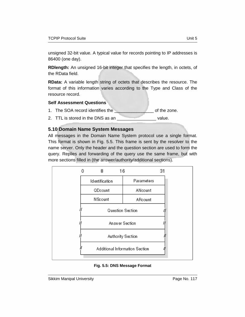
TCPIP Protocol Suite Unit 5
Sikkim Manipal University Page No. 117
unsigned 32-bit value. A typical value for records pointing to IP addresses is
86400 (one day).
RDlength: An unsigned 16-bit integer that specifies the length, in octets, of
the RData field.
RData: A variable length string of octets that describes the resource. The
format of this information varies according to the Type and Class of the
resource record.
Self Assessment Questions
1. The SOA record identifies the ________________ of the zone.
2. TTL is stored in the DNS as an ________________ value.
5.10 Domain Name System Messages
All messages in the Domain Name System protocol use a single format.
This format is shown in Fig. 5.5. This frame is sent by the resolver to the
name server. Only the header and the question section are used to form the
query. Replies and forwarding of the query use the same frame, but with
more sections filled in (the answer/authority/additional sections).
Fig. 5.5: DNS Message Format

TCPIP Protocol Suite Unit 5
Sikkim Manipal University Page No. 118
Header Format: The header section is always present and has a fixed
length of 12 bytes. The other sections are of variable length.
ID: A 16-bit identifier assigned by the program. This identifier is copied in
the corresponding reply from the name server and can be used for
differentiation of responses when multiple queries are outstanding at the
same time.
Parameters: A 16-bit value in the following format (Fig. 5.6).
Fig. 5.6: Parameters
Where:
QR Flag identifying a query (0) or a response(1).
Op code 4-bit field specifying the kind of query:
0 Standard query (QUERY)
1 Inverse query (IQUERY)
2 Server status request (STATUS)
Other values are reserved for future use:
AA: Authoritative answer flag. If set in a response, this flag specifies that the
responding name server is an authority for the domain name sent in the
query.
TC: Truncation flag. Set if message was longer than permitted on the
physical channel.
RD: Recursion desired flag. This bit signals to the name server that
recursive resolution is asked for. The bit is copied to the response.
RA: Recursion available flag. Indicates whether the name server supports
recursive resolution.
Zero: 3 bits reserved for future use. Must be zero.
Rcode: 4-bit response code. Possible values are:

TCPIP Protocol Suite Unit 5
Sikkim Manipal University Page No. 119
0 No error.
1 Format error. The server was unable to interpret the message.
2 Server failure. The message was not processed because of a problem
with the server.
3 Name error. The domain name in the query does not exist. This is only
valid if the AA bit is set in the response.
4 Not implemented. The requested type of query is not implemented by
name server.
5 Refused. The server refuses to respond for policy reasons. Other values
are reserved for future use.
QDcount: An unsigned 16-bit integer specifying the number of entries in the
question section.
ANcount: An unsigned 16-bit integer specifying the number of RRs in the
answer section.
NScount: An unsigned 16-bit integer specifying the number of name server
RRs in the authority section.
ARcount: An unsigned 16-bit integer specifying the number of RRs in the
additional records section.
Question Section: The next section contains the queries for the name
server. It contains QDcount (usually 1) entries, each in the format shown in
Fig. 5.7.
Fig. 5.7: DNS Question Format

TCPIP Protocol Suite Unit 5
Sikkim Manipal University Page No. 120
Where:
Length: A single byte giving the length of the next label.
Label: One element of the domain name characters (for example, ibm from
ral.ibm.com). The domain name referred to by the question is stored as a
series of these variable length labels, each preceded by a 1-byte length.
00: X'00' indicates the end of the domain name and represents the null label
of the root domain.
Type: 2 bytes specifying the type of query. It can have any value from the
Type field in a resource record.
Class: 2 bytes specifying the class of the query. For Internet queries, this
will be IN.
For example, the domain name mydiv.mycorp.com is encoded with the
following fields:
X'05'
"mydiv"
X'06'
"mycorp"
X'03'
"com"
X'00'
Therefore, the entry in the question section for mydiv.mycorp.com requires
22 bytes: 18 to store the domain name and 2 each for the Qtype and Qclass
fields.
Answer, Authority, and Additional Resource Sections: These three
sections contain a variable number of resource records. The number is
specified in the corresponding field of the header. The resource records are
in the format shown in Fig. 5.8.

TCPIP Protocol Suite Unit 5
Sikkim Manipal University Page No. 121
Fig. 5.8: DNS: Answer Record Entry Format
Where the fields before the TTL field have the same meanings as for a
question entry and:
TTL: A 32-bit time-to-live value in seconds for the record. This defines how
long it can be regarded as valid.
RDlength: A 16-bit length for the Rdata field.
Rdata: A variable length string whose interpretation depends on the Type
field.
5.10.1 Message Compression
In order to reduce the message size, a compression scheme is used to
eliminate the repetition of domain names in the various RRs. Any duplicate
domain name or list of labels is replaced with a pointer to the previous
occurrence. The pointer has the form of a 2-byte field as shown in Fig. 5.9
Fig. 5.9: DNS Message Compression
TCPIP Protocol Suite Unit 5
Sikkim Manipal University Page No. 122
Where:
The first 2 bits distinguish the pointer from a normal label, which is
restricted to a 63-byte length plus the length byte ahead of it (which has
a value of <64).
The offset field specifies an offset from the start of the message. A zero
offset specifies the first byte of the ID field in the header.
If compression is used in an Rdata field of an answer, authority, or
additional section of the message, the preceding RDlength field contains
the real length after compression is done.
Self Assessment Questions
1. The header section in DNS message has a fixed length of --------------
bytes.
5.11 Using the DNS Uniform Resource Identifiers (URI)
A DNS can also be queried using a Uniform Resource Identifier. This is
defined in RFC 4501. Strings are not case sensitive, and adhere to the
following format: “dns:” + [ “//” + dnsauthority + “:” + port + ”/” ] + dnsname +
[ “?” + dnsquery ]
Where:
Dnsauthority: The DNS server to which the query should be sent. If this is
left blank, the query is sent to the default DNS server
Dnsname: The name or IP address to be queried.
Dnsquery: The type of the query to be performed. This can be any
combination, separated by a semicolon (;), of:
CLASS: Usually IN for internet, the class of the query
TYPE: The type of resource record desired
For example, a request using the URI to resolve www.myCorp.com to an IP
address might appear as follows:
dns:www.mycorp.com
Additionally, the same request can be sent to the server at 10.1.2.3 on port
5353 using the following:
dns://10.1.2.3:5353/www.mycorp.com

TCPIP Protocol Suite Unit 5
Sikkim Manipal University Page No. 123
5.12 A Simple Scenario
Consider a stand-alone network (no outside connections), consisting of two
physical networks:
One has an Internet network address of 129.112.
One has a network address of 194.33.7.
They are interconnected by an IP gateway (VM2). See Fig. 5.10 for more
details.
Fig. 5.10: DNS: A Simple Configuration
Assume the name server function has been assigned to VM1. Remember
that the domain hierarchical tree forms a logical tree, completely
independent of the physical configuration. In this simple scenario, there is
only one level in the domain tree, which will be referred to as test. example.
5.13 Summary
The Domain Name System (DNS) is a way to resolve meaningful and easy-
to-remember names to IP addresses. Domains names often reflect the
hierarchical delegation of authority used to assign them. The Domain Name
System's distributed database is composed of resource records (RRs),
which are divided into classes for different kinds of networks. All messages
in the Domain Name System protocol use a single format.

TCPIP Protocol Suite Unit 5
Sikkim Manipal University Page No. 124
5.14 Terminal Questions
1. Country domains are also called as __________ .
2. If domain name does not end in a dot, it is incomplete and the
_________ may complete this by appending a suffix.
3. To achieve compression, any duplicate domain name or list of labels is
replaced with a __________.
5.15 Answers for Self Assessment Questions
5.3 1) FQDN
2) True
5.4 1) name server
5.5 1) in-addr.arpa.
5.6 1) resource records
5.7 1) False
2) Recursion desired flag
5.8 1) zone transfer
2) caching only
5.9 1) domain name
2) unsigned 32-bit
5.10 1) 12
5.16 Answers for Terminal Questions
1. geographic domains
2. DNS resolver
3. pointer to previous occurrence
5.17 Exercises
1. Differentiate between FQDN and PQDN.
2. Explain the DNS message format.
3. Clearly differentiate between recursive and iterative DNS query.
4. Discuss the various steps in domain name resolution

TCPIP Protocol Suite Unit 6
Sikkim Manipal University Page No. 125
Unit 6 Remote Execution
Structure
6.1 Introduction
6.2 Telnet
Telnet Operation
Network Virtual Terminal
Telnet Command Structure
Option Negotiation
Telnet Basic Commands
6.3 Remote Execution Command Protocol (REXEC and RSH)
Principle of Operation
6.4 Summary
6.5 Terminal Questions
6.6 Answers for Self Assessment Questions
6.7 Answers for Terminal Questions
6.8 Exercises
6.1 Introduction
One of the most fundamental mechanisms employed on networked
computers is the ability to execute on the remote systems. That is, a user
wants to invoke an application on a remote machine. A number of
application protocols exist to allow this remote execution capability, most
notably the Telnet protocol.
Objectives:
After the completion of this unit you will be able to understand:
Network Virtual Concepts.
OPTION negotiation in TELNET
Structure of TELNET command
6.2 Telnet
Telnet is a standard protocol with STD number 8. Its status is
recommended. It is described in RFC 854 – Telnet Protocol Specifications
and RFC 855 – Telnet Option Specifications. The Telnet protocol provides a
standardized interface, through which a program on one host (the Telnet
client) can access the resources of another host (the Telnet server) as

TCPIP Protocol Suite Unit 6
Sikkim Manipal University Page No. 126
though the client were a local terminal connected to the server. See Fig. 6.1
for more details. For example, a user on a workstation on a LAN can
connect to a host attached to the LAN as though the workstation were a
terminal attached directly to the host. Of course, Telnet can be used across
WANs as well as LANs.
Fig. 6.1: Telnet Operation
Most Telnet implementations do not provide you with graphics capabilities.
6.2.1 Telnet Operation
Telnet protocol is based on three ideas:
1. The Network Virtual Terminal (NVT) concept. An NVT is an imaginary
device with a basic structure common to a wide range of real terminals.
Each host maps its own terminal characteristics to those of an NVT and
assumes that every other host will do the same.
2. A symmetric view of terminals and processes.
3. Negotiation of terminal options. The principle of negotiated options is
used by the Telnet protocol, because many hosts want to provide
additional services, beyond those available with the NVT. Various
options can be negotiated. The server and client use a set of

TCPIP Protocol Suite Unit 6
Sikkim Manipal University Page No. 127
conventions to establish the operational characteristics of their Telnet
connection through the “DO, DONT, WILL, WONT” mechanism
discussed later in this chapter.
The two hosts begin by verifying their mutual understanding. After this initial
negotiation is complete, they are capable of working on the minimum level
implemented by the NVT. After this minimum understanding is achieved,
they can negotiate additional options to extend the capabilities of the NVT to
reflect more accurately the capabilities of the real hardware in use. Because
of the symmetric model used by Telnet (see Fig. 6.2), both the host and the
client can propose additional options to be used.
Fig. 6.2: Telnet Negotiations
6.2.2 Network Virtual Terminal
The NVT has a printer (or display) and a keyboard. The keyboard produces
outgoing data, which is sent over the Telnet connection. The printer receives
the incoming data. The basic characteristics of an NVT, unless they are
modified by mutually agreed options, are:
The data representation is 7-bit ASCII transmitted in 8-bit bytes.
The NVT is a half-duplex device operating in a line-buffered mode.
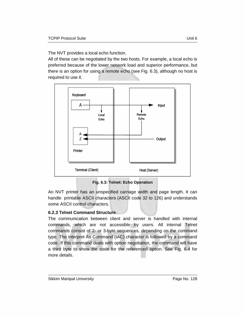
TCPIP Protocol Suite Unit 6
Sikkim Manipal University Page No. 128
The NVT provides a local echo function.
All of these can be negotiated by the two hosts. For example, a local echo is
preferred because of the lower network load and superior performance, but
there is an option for using a remote echo (see Fig. 6.3), although no host is
required to use it.
Fig. 6.3: Telnet: Echo Operation
An NVT printer has an unspecified carriage width and page length. It can
handle printable ASCII characters (ASCII code 32 to 126) and understands
some ASCII control characters.
6.2.3 Telnet Command Structure
The communication between client and server is handled with internal
commands, which are not accessible by users. All internal Telnet
commands consist of 2- or 3-byte sequences, depending on the command
type. The Interpret As Command (IAC) character is followed by a command
code. If this command deals with option negotiation, the command will have
a third byte to show the code for the referenced option. See Fig. 6.4 for
more details.

TCPIP Protocol Suite Unit 6
Sikkim Manipal University Page No. 129
Fig. 6.4: Internal telnet command proposes negotiation about terminal type
Table 6.1 shows some of the possible command codes.
Table 6.1: Some possible command codes
6.2.4 Option Negotiation
Using internal commands, Telnet is able to negotiate options in each host.
The starting base of negotiation is the NVT capability: Each host to be
connected must agree to this minimum. Every option can be negotiated by

TCPIP Protocol Suite Unit 6
Sikkim Manipal University Page No. 130
the use of the four command codes WILL, WONT, DO, and DONT. In
addition, some options have suboptions.
6.2.5 Telnet Basic Commands
The primary goal of the Telnet protocol is the provision of a standard
interface for hosts over a network. To allow the connection to start, the
Telnet protocol defines a standard representation for some functions:
IP Interrupt Process
AO Abort Output
AYT Are You There
EC Erase Character
EL Erase Line
SYNCH Synchronize
Self Assessment Questions
1. State TRUE/FALSE: The Interpret As Command (IAC) character is
followed by a command code.
2. All internal Telnet commands consist of __________ byte sequences,
depending on the command type.
6.3 Remote Execution Command Protocol (REXEC and RSH)
Remote Execution Command Daemon (REXECD) is a server that allows the
execution of jobs submitted from a remote host over the TCP/IP network.
The client uses the REXEC or Remote Shell Protocol (RSH) command to
transfer the job across to the server. Any standard output or error output is
sent back to the client for display or further processing.
6.3.1 Principle of Operation
REXECD is a server (or daemon). It handles commands issued by foreign
hosts and transfers orders to subordinate virtual machines for job execution.
The daemon performs automatic login and user authentication when a user
ID and password are entered. The REXEC command is used to define the
user ID, password, host address, and the process to be started on the
remote host. However, RSH does not require you to send a user name and
password; it uses a host access file instead. Both server and client are
linked over the TCP/IP network. REXEC uses TCP port 512 and RSH uses
TCP port 514. See Fig. 6.5 for more details.

TCPIP Protocol Suite Unit 6
Sikkim Manipal University Page No. 131
Fig. 6.5: REXEC: REXECD Principle
Self Assessment Questions
1. SH does not require you to send a user name and password; it uses a
_______ instead.
2. State TRUE/FALSE: REXEC uses UDP port 512.
6.4 Summary
The Telnet protocol provides a standardized interface, through which a
program on one host (the Telnet client) can access the resources of another
host (the Telnet server) as though the client were a local terminal connected
to the server. The communication between client and server is handled with
internal commands, which are not accessible by users. Using internal
commands, Telnet is able to negotiate options in each host.
6.5 Terminal Questions
1. State TRUE/FALSE: An NVT is an imaginary device with a basic
structure common to a wide range of real terminals.
2. ___________command shows refusal to use or continue to use options.

TCPIP Protocol Suite Unit 6
Sikkim Manipal University Page No. 132
6.6 Answers for Self Assessment Questions
6.2 1) True
2) 2 or 3
6.3 1) host access file
2) False
6.7 Answers for Terminal Questions
1. True
2. WONT
6.8 Exercises
1. What do you mean by “OPTION NEGOTIATION”? Explain with an
example.
2. Explain the principle of operation of REXEC protocol.

TCPIP Protocol Suite Unit 7
Sikkim Manipal University Page No. 133
Unit 7 FTP and TFTP
Structure
7.1 Introduction
7.2 File Transfer Protocol (FTP)
An overview of FTP
FTP Operations
7.3 Trivial File Transfer Protocol (TFTP)
TFTP Usage
Protocol Description
TFTP Packets
Data Modes
TFTP Multicast Option
Security Issues
7.4 Summary
7.5 Terminal Questions
7.6 Answers for Self Assessment Questions
7.7 Answers for Terminal Questions
7.8 Exercises
7.1 Introduction
The TCP/IP protocol suite provides a number of protocols for the
manipulation of files. In general, there are two different mechanisms for
accessing remote files. The most simple mechanism is by transferring the
particular file to the local machine. In this case, multiple copies of the same
file are likely to exist. File Transfer Protocol (FTP), Trivial File Transfer
Protocol (TFTP), Secure Copy (SCP), and SSH FTP (SFTP) employ this
mechanism of file sharing .In this chapter we discuss FTP and TFTP.
Objectives:
After the completion of this chapter you will be able to understand:
Operations performed by user using FTP
TFTP basics
Significance of TFTP multicast option.

TCPIP Protocol Suite Unit 7
Sikkim Manipal University Page No. 134
7.2 File Transfer Protocol (FTP)
FTP is a standard protocol with STD Number 9. Its status is recommended.
It is described in RFC 959 – File Transfer Protocol (FTP) and updated by
RFCs 2228 (FTP Security Extensions), 2428 (FTP Extensions for IPv6 and
NATs), and 4217 (Securing FTP with TLS). Additional information is in RFC
2577 (FTP Security Considerations).
Transferring data from one host to another is one of the most frequently
used operations. Both the need to upload data (transfer data from a client to
a server) and download data (retrieve data from a server to a client) are
addressed by FTP. Additionally, FTP provides security and authentication
measures to prevent unauthorized access to data.
7.2.1 An overview of FTP
FTP uses TCP as a transport protocol to provide reliable end-to-end
connections and implements two types of connections in managing data
transfers. The FTP client initiates the first connection, referred to as the
control connection, to well-known port 21 (the client’s port is typically
ephemeral). It is on this port that an FTP server listens for and accepts new
connections. The control connection is used for all the control commands a
client user uses to log on to the server, manipulate files, and terminate a
session. This is also the connection across which the FTP server will send
messages to the client in response to these control commands. The second
connection used by FTP is referred to as the data connection.
Typically, the data connection is established on server port 20. However,
depending on how the data connection is established, both the client and
server might use ephemeral ports. It is across this connection that FTP
transfers the data. FTP only opens a data connection when a client issues a
command requiring a data transfer, such as a request to retrieve a file, or to
view a list of the files available. Therefore, it is possible for an entire FTP
session to open and close without a data connection ever having been
opened. Unlike the control connection, in which commands and replies can
flow both from the client to the server and from the server to the client, the
data connection is unidirectional. FTP can transfer data only from the client
to the server or from the server to the client, but not both. Also, unlike the
control connection, the data connection can be initiated from either the client
or the server. Data connections initiated by the server are active, while

TCPIP Protocol Suite Unit 7
Sikkim Manipal University Page No. 135
those initiated by the client are passive. The client FTP application is built
with a protocol interpreter (PI), a data transfer process (DTP), and a user
interface. The server FTP application typically only consists of a PI and DTP
(see Fig.7.1).
Fig. 7.1: The FTP Model
The FTP client’s user interface communicates with the protocol interpreter,
which manages the control connection. This protocol interpreter translates
any application-specific commands to the RFC architected FTP commands,
and then communicates these control commands to the FTP server. The
FTP server’s PI receives these commands, and then initiates the
appropriate processes to service the client’s requests. If the requests
require the transfer of data, data management is performed by the DTPS on
both the client and server applications. Following the completion of the data
transfer, the data connection is closed, and control is returned to the PIs of
the client and server applications.
7.2.2 FTP Operations
When using FTP, the user performs some or all of the following operations:
Connect to a remote host
TCPIP Protocol Suite Unit 7
Sikkim Manipal University Page No. 136
Navigate and manipulate the directory structure.
List files available for transfer.
Define the transfer mode, transfer type and data structure.
Transfer data to or from the remote host.
Disconnect from the remote host.
Connecting to a remote host
To execute a file transfer, the user begins by logging in to the remote host.
This is only the primary method of implementing security within the FTP
model. Additional security can be provided using SSL and TLS. Conversely,
this authentication can be bypassed using anonymous FTP . There are four
commands that are used:
Open: Selects the remote host and initiates the login session.
User: Identifies the remote user ID.
Pass: Authenticates the user.
Site: Sends information to the foreign host that is used to provide services
specific to that host.
Navigating the directory structure
After a user has been authenticated and logged on to the server, that user
can navigate through the directory structure of the remote host in order to
locate the file desired for retrieval, or locate the directory into which a local
file will be transferred. The user can also navigate the directory structure of
the client’s host. After the correct local and remote directories have been
accessed, users can display the contents of the remote directory. The
subcommands that perform these functions are as follows:
cd: Changes the directory on the remote host: A path name can be
specified, but must conform to the directory structure of the remote host. In
most implementations, cd .. will move one directory up within the directory
structure.
Lcd: Changes the directory on the local host. Similar to the cd command, a
path name can be specified but must conform to the directory structure of
the local host.
Ls: Lists the contents of the remote directory. The list generated by this
command is treated as data, and therefore, this command requires the use

TCPIP Protocol Suite Unit 7
Sikkim Manipal University Page No. 137
of a data connection. This command is intended to create output readable
by human users.
Dir: Lists the contents of the remote directory. Similar to the ls command,
the list generated by dir is treated as data and requires the use of a data
connection. This command is intended to create output readable by
programs.
Controlling the data transfer
Transferring data between dissimilar systems often requires transformations
of the data as part of the transfer process. The user has to decide on three
aspects of the data handling:
The way the bits will be moved from one place to another
The different representations of data on the system's architecture
The file structure in which the data is to be stored
Each of these is controlled by a subcommand:
Mode: Specifies whether the file is treated as having a record structure in a
byte stream format:
B: This specifies block mode is to be used. This indicates that the logical
record boundaries of the file are preserved.
S: This specifies that stream mode is to be used, meaning that the file is
treated as a byte stream. This is the default and provides more efficient
transfer but might not produce the desired results when working with a
record-based file system.
Type: Specifies the character sets used in translating and representing the
data:
A: Indicates that both hosts are ASCII-based, or that if one is ASCII-based
and the other is EBCDIC-based, that ASCII-EBCDIC translation must be
performed. On many implementations, this can be invoked by issuing the
ASCII command, which the PI translates into the type A ommand.
E: Indicates that both hosts use an EBCDIC data representation. On many
implementations, this can be invoked by issuing the EBCDIC command,
which the PI translates into the type E command.

TCPIP Protocol Suite Unit 7
Sikkim Manipal University Page No. 138
I: Indicates that no translation is to be done on the data. On many
implementations, this can be invoked by using the BINARY command,
which the PI translates into the type I command.
Structure: Specifies the structure of the file to be transferred:
File: Indicates that the file has no internal structure, and is considered to be
a continuous sequence of data bytes.
Record: Indicates that the file is made up of sequential records.
Page: Indicates that the file is made up of independent indexed pages.
Because these subcommands do not cover all possible differences between
systems, the site subcommand is available to issue implementation-
dependent and platform-specific commands. The syntax of this command
will vary by implementation.
Transferring files
The following commands can be used to copy files between FTP clients and
servers:
Get: Copies a file from the remote host to the local host. The PI translates
get: into a RETR command.
Mget: Copies multiple files from the remote to the local host. The PI
translates mget into a series of RETR commands.
Put: Copies a file from the local host to the remote host. The PI translates
put into a STOR command.
Mput: Copies multiple files from the local host to the remote host. The PI
translates mput into a series of STOR commands.
Terminating the FTP session
The following commands are used to end an FTP session:
Quit: Disconnects from the remote host and terminates FTP. Some
implementations use the BYE subcommand.
Close: Disconnects from the remote host but leaves the FTP client running.
An open command can be issued to establish a new control connection.
An example of an FTP scenario
A LAN user has to transfer data from a workstation to the remote host
remote.host. The data is binary, and exists in a file structure named mydata

TCPIP Protocol Suite Unit 7
Sikkim Manipal University Page No. 139
in the workstation’s /localfolder directory. The user wants to transfer the
data, using stream mode, to the remote host’s /tmp directory, and would like
the new file to be named yourdata. The process for doing this is illustrated in
Fig. 7.2.
Fig. 7.2: An example of an FTP transfer
The active data transfer
When issuing the subcommands get, put, mget, mput, ls, or dir, FTP
opens a data connection across which the data will be transferred. Most
FTP implementations default to an active data transfer unless a passive
transfer has been specifically requested. In an active transfer, the FTP client
sends a PORT command to the FTP server, indicating the IP address and
port number on which the client will listen for a connection. Upon accepting
the PORT command, the FTP server initiates a connection back to the client
on the indicated IP address and port. After this connection has been
established, data will begin flowing, either from the client to the server (for

TCPIP Protocol Suite Unit 7
Sikkim Manipal University Page No. 140
put and mput commands) or from the server to the client (for get, mget, ls,
and dir commands). An example of this sequence is illustrated in Fig. 7.3.
Fig. 7.3: The active data connection
The passive data transfer
Contrary to the use of an active data connection, the passive data transfer
reverses the direction of establishment of the data connection. Instead of
issuing a PORT command, the client issues a PASV command, which uses
no parameters. Upon accepting this command, the FTP server sends back a
reply containing an IP address and port number. The client initiates a
connection back to the server on the indicated IP address and port. An
example of this sequence is illustrated in Fig. 7.4.

TCPIP Protocol Suite Unit 7
Sikkim Manipal University Page No. 141
Fig. 7.4: The passive data connection
One of the reasons to use a passive data transfer is to bypass firewall
configurations that block active data connections. For this reason, passive
mode is often referred to as “firewall friendly mode.” An example of such a
scenario is a firewall that has been configured to block any inbound
attempts to open a connection. In this example, an FTP server responding
to a client’s PORT command would receive an error when trying to open a
connection to the indicated IP address and port. However, by using passive
mode, the client initiates the connection from within the network, and the
firewall allows the data transfer to proceed.

TCPIP Protocol Suite Unit 7
Sikkim Manipal University Page No. 142
Using proxy transfer
FTP provides the ability for a client to have data transferred from one FTP
server to another FTP server. Several justifications for such a transfer exist,
including:
To transfer data from one host to another when direct access to the two
hosts are not possible.
To bypass a slow client connection.
To bypass a firewall restriction.
To reduce the amount of traffic within the client’s network
The process of setting up a proxy transfer begins with the use of a proxy
open command. Any FTP command can then be sent to the proxy server by
preceding the command with proxy. For example, executing the dir
command lists the files on the primary FTP server. Executing the proxy dir
command lists the files on the proxy server. The proxy get and proxy put
commands can then be used to transfer data between the two hosts.
Fig. 7.5: An FTP proxy transfer through firewall

TCPIP Protocol Suite Unit 7
Sikkim Manipal University Page No. 143
In Fig. 7.5:
1. The FTP client opens a connection and logs on to the FTP server A.
2. The FTP client issues a proxy open command, and a new control
connection is established with FTP server B.
3. The FTP client then issues a proxy get command (though this can also
be a proxy put).
4. A data connection is established between server A and server B.
Following data connection establishment, the data flows from server B to
server A.
Reply codes
In order to manage these operations, the client and server conduct a dialog
using the Telnet convention. The client issues commands, and the server
responds with reply codes. The responses also include comments for the
benefit of the user, but the client application uses only the codes. Reply
codes are three digits long, with the first two digits having specific meanings.
See Table 7.1 and Table 7.2 for descriptions of these codes.
Table 7.1: First digit reply codes and descriptions
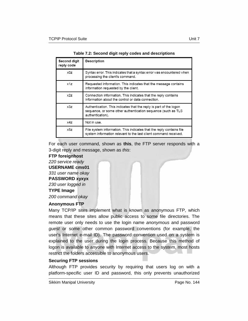
TCPIP Protocol Suite Unit 7
Sikkim Manipal University Page No. 144
Table 7.2: Second digit reply codes and descriptions
For each user command, shown as this, the FTP server responds with a
3-digit reply and message, shown as this:
FTP foreignhost
220 service ready
USERNAME cms01
331 user name okay
PASSWORD xyxyx
230 user logged in
TYPE Image
200 command okay
Anonymous FTP
Many TCP/IP sites implement what is known as anonymous FTP, which
means that these sites allow public access to some file directories. The
remote user only needs to use the login name anonymous and password
guest or some other common password conventions (for example, the
user's Internet e-mail ID). The password convention used on a system is
explained to the user during the login process. Because this method of
logon is available to anyone with Internet access to the system, most hosts
restrict the folders accessible to anonymous users.
Securing FTP sessions
Although FTP provides security by requiring that users log on with a
platform-specific user ID and password, this only prevents unauthorized

TCPIP Protocol Suite Unit 7
Sikkim Manipal University Page No. 145
access to the system itself. When transferring data from one host to
another, the data within the packets (both on the control connection and the
data connection) is sent in clear text. Therefore, network tools such as
packet traces and sniffer devices can capture the packets and gain access
to the transferred data. Additionally, the user ID and password used to log
on to the server can be captured in these traces, giving a malicious user
access to the system.
To avoid this problem, the design of FTP has been enhanced to make use
of Transport Layer Security (TLS). TLS is defined in RFC 4366, and defines
a standard of data encryption between two hosts. As denoted by its name,
TLS is implemented on the transport layer, and thus applications using TLS
do not need to know the specifics of RFC 4366. Instead, such applications
only need to know how to invoke TLS, and in the case of FTP, this process
is defined by RFCs 2228 and 4217.
The configuration and implementation of TLS varies by platform. However,
RFCs 2228 and 4217 add to the FTP architecture the following TLS-related
commands, which invoke TLS regardless of the platform’s specific
configuration process:
AUTH: Specifies the authentication method to be used in securing the FTP
connection.
ADAT: Passes Base64-encoded security data, specific to the mechanism
specified on the AUTH command, used to in the security negotiation
between the client and server.
PBSZ: Specifies the largest buffer size in which encrypted data can be
passed between the client and server.
PROT: Specifies the data channel protection level. The argument passed
must be one of the following:
C Clear: Neither authentication nor encryption is used.
S Safe: Authentication is performed, but no encryption is implemented.
E Confidential: Encryption is performed, but no authentication is
implemented.
P Private: Both encryption and authentication are performed.

TCPIP Protocol Suite Unit 7
Sikkim Manipal University Page No. 146
MIC: Provides a Base64-encoded message used to integrity protect
commands sent on the control connection.
CONF: Provides a Base64-encoded message used to confidentially protect
commands sent on the control connection.
ENC: Provides a Base64-encoded message used to privately protect
commands sent on the control connection.
CCC: Instructs the FTP server that integrity-protected commands are no
longer required for the FTP session.
Fig. 7.6 shows an example of a common security negotiation using these
commands.
Fig. 7.6: An example of FTP TLS processing
Most FTP client and server implementations provide configuration options to
automate the security negotiation using the previous commands. This

TCPIP Protocol Suite Unit 7
Sikkim Manipal University Page No. 147
makes the implementation of secure FTP easier for the user because users
do not need to understand or implement the details of the security during the
FTP session itself, and only are prompted for a user ID and possibly a
password.
Self Assessment Questions
1. FTP uses __________ as a transport protocol.
2. The server FTP application typically consists of a PI and _________.
3. The _________ subcommand, lists the contents of the remote directory.
4. Passive mode is often referred to as ____________ .
5. The process of setting up a proxy transfer begins with the use of a
_____________ command.
7.3 Trivial File Transfer Protocol (TFTP)
The Trivial File Transfer Protocol (TFTP) is a standard protocol with STD
number 33. Its status is elective and it is described in RFC 1350™ – The
TFTP Protocol (Revision 2). Updates to TFTP are in the RFCs: 1785, 2347,
2348, and 2349. TFTP file transfer is a disk-to-disk data transfer, and is an
simple protocol used to transfer files. The simplicity of the architecture is
deliberate in order to facilitate ease of implementation. This simplistic
approach has many benefits over traditional FTP, including:
Use by diskless devices to download firmware at boot time
Use by any automated process for which the assignment of a user ID or
password is not feasible
Small application size, allowing it to be implemented inexpensively and
in environments where resources are constricted
TFTP is implemented on top of the User Datagram Protocol. The TFTP
client initially sends read/write request through well-known port 69. The
server and the client then determine the port that they will use for the rest of
the connection. TFTP lacks most of the features of FTP, and instead is
limited to only reading a file from a server or writing a file to a server.
7.3.1 TFTP usage
The commands used by TFTP implementations are not architected by an
RFC. Instead, only the direct interaction between a TFTP server and client
are defined. Therefore, the commands used to invoke this interaction vary

TCPIP Protocol Suite Unit 7
Sikkim Manipal University Page No. 148
between different implementations of this protocol. However, each
implementation has some variation of the following commands:
Connect <host> Specifies the destination host ID.
Mode <ascii|binary> Specifies the type of transfer mode.
Get <remote filename> [<local filename>] Retrieves a file.
Put <remote filename> [<local filename>] Stores a file.
Verbose Toggles verbose mode, which displays additional information
during file transfer, on or off.
Quit Exits TFTP.
For a full list of these commands, see the user's guide of your particular
TFTP implementation.
7.3.2 Protocol description
Every TFTP transfer begins with a request to read or write a file. If the
server grants the request, the connection is opened and the file is sent in
blocks of 512 bytes (fixed length). Blocks of the file are numbered
consecutively, starting at 1, and each packet carries exactly one block of
data. Each data packet must be answered by an acknowledgment packet
before the next one can be sent. Termination of the transfer is assumed on
a data packet of less than 512 bytes. Although almost all errors will cause
termination of the connection due to lack of reliability, TFTP can recover
from packet loss. If a packet is lost in the network, a timeout occurs,
initiating a retransmission of the last packet. This retransmission occurs both
for lost data blocks or lost acknowledgements.
The requirement that every packet be acknowledged–including
retransmissions uncovered a design flaw in TFTP known as the Sorcerer's
Apprentice Syndrome (SAS), described in RFC 783. On networks that
experience latency or other delays, this flaw might cause excessive
retransmission by both sides of the TFTP implementation. SAS was further
documented in RFC 1123 and later corrected by adding OACK packets as a
TFTP extension, described in RFC 2347. For additional details, refer to the
appropriate RFCs.

TCPIP Protocol Suite Unit 7
Sikkim Manipal University Page No. 149
7.3.3 TFTP packets
TFTP uses six types of packets, described in Table 7.3.
The TFTP header contains the opcode associated with the packet. See
Fig. 7.7 for more details.
Fig. 7.7: TFTP packet headers
7.3.4 Data modes
Two modes of transfer are currently defined in RFC 1350:

TCPIP Protocol Suite Unit 7
Sikkim Manipal University Page No. 150
NetASCII: US-ASCII, as defined in the USA Standard Code for Information
Interchange with modifications specified in RFC 854 – Telnet Protocol
Specification and extended to use the high order bit. (That is, it is an 8-bit
character set, unlike US-ASCII, which is 7-bit.)
Octet: Raw 8-bit bytes, also called binary. The mode used is indicated in
the TFTP header for the Request for Read/Write packets (RRQ/WRQ).
7.3.5 TFTP multicast option
The TFTP multicast option enables multiple clients to get files
simultaneously from the server using the multicast packets. For example,
when two similar machines are remotely booted, they can retrieve the same
configuration file simultaneously by adding the multicast option to the TFTP
option set. The TFTP multicast option is described in RFC 2090. Fig. 7.8 is
an example of a TFTP read request packet modified to include the multicast
option.
Fig. 7.8: The TFTP Multicast header
If the server accepts the multicast, it sends an option acknowledgment
(OACK) packet to the server including the multicast option. This packet
consists of the multicast address and a flag that specifies whether the client
should send acknowledgments (ACK).
7.3.6 Security issues
Because TFTP does not have any authentication mechanism, the server is
responsible for protecting the host files. Generally, TFTP servers do not
allow write access and only allow read access to public directories. Some
server implementations also might employ host access lists to restrict
access to only a subset of hosts.
Self Assessment Questions
1. In TFTP, if the server grants the request, the connection is opened and
the file is sent in blocks of _____________ .
2. State TRUE/FALSE: TFTP lacks most of the features of FTP, and
instead is limited to only reading a file from a server or writing a file to a
server.

TCPIP Protocol Suite Unit 7
Sikkim Manipal University Page No. 151
3. State TRUE/FALSE: Generally, TFTP servers allow write access and
only allow read access to public directories.
7.4 Summary
FTP uses TCP as a transport protocol to provide reliable end-to-end
connections. FTP can transfer data only from the client to the server, or from
the server to the client, but not both. To execute a file transfer, the user
begins by logging in to the remote host. This is only the primary method of
implementing security within the FTP model. Additional security can be
provided using SSL and TLS. This authentication can be bypassed using
anonymous FTP. TFTP file transfer is a disk-to-disk data transfer, and is an
simple protocol used to transfer files. TFTP is implemented on top of the
User Datagram Protocol.
7.5 Terminal Questions
1. State TRUE/FALSE: It is possible for an entire FTP session to open and
close without a data connection ever having been opened.
2. In an active transfer, the FTP client sends a PORT command to the FTP
server, indicating ______________ on which the client will listen for a
connection.
7.6 Answers for Self Assessment Questions
7.2 1) TCP
2) DTP
3) ls
4) Firewall Friendly Mode
5) proxy open
7.3 1) 512 bytes
2) TRUE
3) FALSE
7.7 Answers for Terminal Questions
1. TRUE
2. IP address and PORT number

TCPIP Protocol Suite Unit 7
Sikkim Manipal University Page No. 152
7.8 Exercises
1. Explain various operations performed by the user with FTP.
2. Discuss FTP proxy transfer through firewall.
3. Explain the mechanisms used to secure FTP sessions.
4. Discuss the salient features of TFTP.
TCPIP Protocol Suite Unit 8
Sikkim Manipal University Page No. 153
Unit 8 Mail Applications
Structure
8.1 Introduction
8.2 Simple Mail Transfer Protocol
How SMTP Works
SMTP Messages
The SMTP Destination Address
Mail Header Format
Mail Exchange
SMTP Mail Transaction Flow
An Additional Example
8.3 Post Office Protocol (POP)
Connection States
POP3 Commands and Responses
8.4 Internet Message Access Protocol (IMAP4)
Fundamental IMAP4 Electronic mail models
IMAP4 states
IMAP4 commands and response interaction
IMAP4 messages
8.5 Summary
8.6 Terminal Questions
8.7 Answers for Self Assessment Questions
8.8 Answers for Terminal Questions
8.9 Exercises
8.1 Introduction
Electronic mail (e-mail) is probably the most widely used TCP/IP application
in the Internet community today. For most people, it has become an integral
part of everyday life, and it serves as the primary communication vehicle for
most businesses. This chapter provides an overview of the TCP/IP
application protocols dealing with electronic mail, including:
Simple Mail Transport Protocol (SMTP)
Post Office Protocol (POP)
Internet Message Access Protocol (IMAP)

TCPIP Protocol Suite Unit 8
Sikkim Manipal University Page No. 154
Objectives:
After the completion of this chapter you will be able to understand:
Working of SMTP
SMTP message format
SMTP model
POP protocol, commands and responses
IMAP4 and its differences with POP
IMAP4 messages
8.2 Simple Mail Transfer Protocol
The basic Internet mail protocols provide mail (note) and message
exchange between TCP/IP hosts, but generally require that data be
represented as 7-bit ASCII text. Because this can be restrictive, facilities
have been added for the transmission of data that cannot be represented in
this manner. Originally, there were three standard protocols that apply to
mail of this kind. The term Simple Mail Transfer Protocol (SMTP) is
frequently used to refer to the combined set of protocols because they are
so closely interrelated.
8.2.1 How SMTP Works
SMTP is based on end-to-end delivery: An SMTP client contacts the
destination host's SMTP server directly, on well-known port 25, to deliver the
mail. It keeps the mail item being transmitted until it has been successfully
copied to the recipient's SMTP. This is different from the store-and-forward
principle that is common in many mailing systems, where the mail item can
pass through a number of intermediate hosts in the same network on its way
to the destination and where successful transmission from the sender only
indicates that the mail item has reached the first intermediate hop.
In various implementations, it is possible to exchange mail between the
TCP/IP SMTP mailing system and the locally used mailing systems. These
applications are called mail gateways or mail bridges. Sending mail through
a mail gateway can alter the end-to-end delivery specification, because
SMTP only guarantees delivery to the mail-gateway host, not to the real
destination host located beyond the TCP/IP network. When a mail gateway
is used, the SMTP end-to-end transmission is host-to-gateway, gateway-to-
host, or gateway-to-gateway; the behavior beyond the gateway is not
defined by SMTP.

TCPIP Protocol Suite Unit 8
Sikkim Manipal University Page No. 155
8.2.2 SMTP Messages
In SMTP, each message has:
A header, or envelope, the structure of which is strictly defined by RFC
2822 The mail header is terminated by a null line (that is, a line with
nothing preceding the <CRLF> sequence).
Contents: Everything after the null (or blank) line is the message body,
which is a sequence of lines containing ASCII characters (that is,
characters with a value less than 128 decimal).
As usual, the client SMTP (referred to as the sending SMTP) is the entity
that initiates the session, and the server (referred to as the receiving SMTP)
is the one that responds to the session request. Because the client SMTP
frequently can also act as a server for a user mailing program, it is often
simpler to refer to the client as the sender SMTP and to the server as the
receiver SMTP.
8.2.3 The SMTP Destination Address
Also known as the mailbox address, the general form of the destination
address is local-part@domain-name and can take several forms:
user@host: For a direct destination on the same TCP/IP network.
user%remote-host@gateway-host: For a user on a non-SMTP destination
remote-host, through the mail gateway-host.
@host-a,@host-b:user@host-c: For a relayed message. This contains
explicit routing information. The message is first delivered to host-a, who re-
sends (relay) the message to host-b. Host-b then forwards the message to
the real destination host-c. Note that the message is stored on each of the
intermediate hosts, so we do not have an end-to-end delivery in this case.
8.2.4 Mail Header Format
Typically, a user does not have to worry about the message header
because it is managed by SMTP itself. A short reference is included here for
completeness. RFC 2822 contains a complete lexical analysis of the mail
header. The syntax is written in a form known as the Augmented Backus-
Naur Form (ABNF), defined in RFC 2822. Additionally, many RFCs related
to RFC 2822 use this format. RFC 2822 also describes how to parse a mail
header to a canonical representation, unfolding continuation lines, deleting
insignificant spaces, removing comments, and so on. The syntax is

TCPIP Protocol Suite Unit 8
Sikkim Manipal University Page No. 156
powerful, but relatively difficult to parse. A basic description is given here,
which should be adequate for you to interpret the
meaning of simple mail headers that might be encountered. Briefly, the
header is a list of specifications in the form of:
keyword: value
Fields begin in column 1. Lines beginning with white space characters
(space or tab) are continuation lines that are unfolded to create a single line
for each field in the canonical representation. Strings enclosed in ASCII
quotation marks indicate single tokens within which special characters, such
as the colon, and are not significant. Many important field values (such as
those for the To and From fields) are mailboxes. The most common forms
for these are:
Your Email <[email protected]>
"Your Email" <[email protected]>
In this example, the string Your Email is intended to be read by human
recipients and is the name of the mailbox owner.
[email protected] is the machine-readable address of
the mailbox (the angle brackets delimit the address but are not part of it).
Table 8.1 lists some frequently used fields.
Table 8.1: Common SMTP header fields

TCPIP Protocol Suite Unit 8
Sikkim Manipal University Page No. 157
A sample header might appear as follows:
From: [email protected]
To: “Your Email” <[email protected]>
cc: “Your Boss” <[email protected]>
Reply-To: [email protected]
Subject: This is a sample SMTP header
8.2.5 Mail Exchange
The SMTP design is based on the model of communication shown in Fig.
8.1. As a result of a user mail request, the sender SMTP establishes a two-
way connection with a receiver SMTP. The receiver SMTP can be either the
ultimate destination or an intermediate (mail gateway). The sender SMTP
will generate commands that are replied to by the receiver SMTP.
Fig. 8.1: The SMTP Model
8.2.6 SMTP Mail Transaction Flow
Although mail commands and replies are rigidly defined, the exchange can
easily be followed in Fig. 8.2. All exchanged commands, replies, and data
are text lines delimited by a <CRLF>. All replies have a numeric code at the
beginning of the line. The steps of this flow are:
1. The sender SMTP establishes a TCP connection with the destination
SMTP and then waits for the server to send a 220 Service ready

TCPIP Protocol Suite Unit 8
Sikkim Manipal University Page No. 158
message or a 421 Service not available message when the destination
is temporarily unable to proceed.
2. HELO (HELO is an abbreviation for hello) is sent, to which the receiver
will identify itself by sending back its domain name. The sender-SMTP
can use this to verify that it contacted the right destination SMTP. The
sender SMTP can substitute an EHLO command in place of the HELO
command. A receiver SMTP that does not support service extensions
will respond with a 500 Syntax Error, command unrecognized message.
The sender SMTP then retries with HELO, or if it cannot transmit the
message without one or more service extensions, it sends a QUIT
message. If a receiver-SMTP supports service extensions, it responds
with a multiline 250 OK message, which includes a list of service
extensions that it supports.
3. The sender now initiates the start of a mail transaction by sending a
MAIL command to the receiver. This command contains the reverse-
path that can be used to report errors. Note that a path can be more
than just the user mailbox@host domain name pair. In addition, it can
contain a list of routing hosts. Examples of this are when we pass a mail
bridge, or when explicit routing information is provided in the destination
address. If accepted, the receiver replies with a 250 OK.
4. The second step of the actual mail exchange consists of providing the
server SMTP with the destinations for the message. There can be more
than one recipient. This is done by sending one or more
RCPTTO:<forward-path> commands. Each of them will receive a reply
250 OK if the destination is known to the server, or a 550 No such user
here if it is not.
5. When all RCPT commands are sent, the sender issues a DATA
command to notify the receiver that the message contents will follow.
The server replies with 354 Start mail input, end with <CRLF>.<CRLF>.
Note the ending sequence that the sender should use to terminate the
message data.
6. The client now sends the data line by line, ending with the 5-character
sequence <CRLF>.<CRLF> line, upon which the receiver will
acknowledge with a 250 OK, or an appropriate error message if anything
went wrong.

TCPIP Protocol Suite Unit 8
Sikkim Manipal University Page No. 159
7. At this juncture, the client now has several possible actions:
If the client has no more messages to send, it can end the
connection with a QUIT command, which will be answered with a
221 Service closing transmission channel reply.
If the sender has no more messages to send, but is ready to receive
messages (if any) from the other side, it can issue the TURN
command. The two SMTPs now switch their role of sender/receiver,
and the sender (previously the receiver) can now send messages by
starting with step 3.
If the sender has another message to send, it returns to step 3 and
sends a new MAIL command.
Fig. 8.2 illustrates the normal transmission of a single message from a
client to a server. Additionally, we provide a textual scenario in Fig. 8.3.
Fig. 8.2: SMTP: Normal SMTP data flow

TCPIP Protocol Suite Unit 8
Sikkim Manipal University Page No. 160
In the previous description, we mentioned only the most important
commands. All of these are commands that must be recognized in each
SMTP implementation. Other commands exist, but are optional. RFC
standards do not require that every SMTP entity implement them. However,
they provide very interesting functions such as relaying, forwarding, mailing
lists, and so on.
8.2.7 An additional example
In the following scenario, user abc at host vm1.stockholm.ibm.com sends a
note to users xyz, opq, and rst at host delta.aus.edu (Fig. 8.3). The lines
preceded by R: are lines sent by the receiver; the S: lines are sent by the
sender.
Fig. 8.3: SMTP: An example-Scenario
Note that the message header is part of the data being transmitted.

TCPIP Protocol Suite Unit 8
Sikkim Manipal University Page No. 161
Self Assessment Questions
1. State TRUE/FALSE: Sending mail through a mail gateway can alter the
end-to-end delivery specification.
2. The SMTP destination address also known as the ____________ .
3. In various implementations, it is possible to exchange mail between the
TCP/IP SMTP mailing system and the locally used mailing systems.
These applications are called ___________ .
8.3 Post Office Protocol (POP)
The Post Office Protocol, version 3, is a standard protocol with STD number
53. Its status is elective, and it is described in RFC 1939. The older Post
Office Protocol version 2, defined in RFC 0937, is a historic protocol with a
status of not recommended. The Post Office Protocol is an electronic mail
protocol with both client (sender/receiver) and server (storage) functions.
POP3 supports basic functions (download and delete) for electronic mail
retrieval. More advanced functions are supported by IMAP4.
8.3.1 Connection states
After a POP3 client establishes a TCP connection to the server (using well-
known port 110), the interaction between the client and server passes
through three distinct states:
1. First, the POP3 server sends a greeting message to the client. Following
this, the session then enters the authentication state. During this state,
the client must authenticate itself to the server. This can be done using
one of three methods:
USER/PASS: The combined use of a user ID and password (defined
in RFC 1939)
APOP: Used to specify a name and an MD5 digest (also defined in
RFC 1939)
AUTH: Used to specify a mechanism (such as TLS) by which both
authentication and data protection can be provided (defined in RFC
1734)
2. If the server successfully authenticates the client, the session enters the
transaction state in which the client can access the mailbox

TCPIP Protocol Suite Unit 8
Sikkim Manipal University Page No. 162
3. After the client sends the QUIT command, the session enters the update
state. During this state, the server enacts all of the changes requested
by the client’s commands and then close the connection. If the
connection is closed, for any reason, before a QUIT command is issued,
none of the client’s commands will take effect.
8.3.2 POP3 Commands and Responses
POP3 commands consist of a keyword and possibly one or more arguments
following the keyword. Keywords are three or four characters long, and are
separated from the arguments by a space. Each argument can be up to 40
characters long. The server must send a response to each command issued
by the client. This response can be up to 512 characters, and must begin
with a status indicator signifying if the reply is positive or negative. These
indicators are +OK or –ERR, and must be sent in uppercase. As noted
previously, POP3 interactions exist in three states. Commands can be
issued from the authorization and transaction states, but not from the update
state. With the exception of the QUIT command (which can be executed in
both the authorization and transaction state), each command can only be
executed in one of the states. Valid POP3 command, listed by state, are as
follows:
Authorization state:
USER name: User name for authentication.
PASS password: Password for authentication.
APOP name digest: The name and MD5 digest to be used for
authentication (RFC 1939 indicates that implementation of this
command is optional).
AUTH mechanism: The authentication/encryption mechanism to be used
(RFC 1734 indicates that implementation of this command is optional).
QUIT: Terminate the authentication process.
Transaction state:
STAT: Retrieve the number of messages and total size of the
messages.
LIST [msg#]: If no msg number is provided, retrieve information about
each message present in the mailbox. If a msg number is specified, the
server returns information for that message.
RETR msg: Retrieve message number msg.

TCPIP Protocol Suite Unit 8
Sikkim Manipal University Page No. 163
DELE msg: Delete message number msg
NOOP: Do nothing. The server returns a positive response.
RSET: Cancel any previous delete commands.
QUIT: Update the mailbox (delete any messages requested previously)
and then end the TCP connection.
Self Assessment Questions
1. POP3 keywords are ______________ characters long, and are
separated from the arguments by a space.
2. The Post Office Protocol is __________ protocol with both client
(sender/receiver) and server (storage) functions.
8.4 Internet Message Access Protocol (IMAP4)
The Internet Message Access Protocol, Version 4 is an electronic
messaging protocol with both client and server functions. It is defined by
RFC 3501. Similar to POP, IMAP4 servers store messages for multiple
users to be retrieved upon client requests, but the IMAP4 model provides
more functionality to users than does the POP model. IMAP4 allows clients
to have multiple remote mailboxes from which messages can be retrieved,
and allows users to choose any of those at any point. IMAP4 clients can
also specify criteria for downloading messages, such as not transferring
large messages over slow links. Additionally, IMAP4 always keeps
messages on the server and replicates copies to the clients.
Another difference between POP and IMAP4 implementations is in the
operational mode. Using POP, a client must always be connected to the
server for changes to be made. However, IMAP4 allows clients to make
changes both when connected and when disconnected. When
disconnected, (referred to as a disconnected client), changes made on the
client take effect on the server by periodic re-synchronization of the client
and server. Let us discuss the underlying electronic mail models of IMAP4
first in order to understand the IMAP4 functions
8.4.1 Fundamental IMAP4 Electronic Mail Models
As defined in RFC 1733, there are three fundamental models implemented
by the IMAP4 client and server: offline, online, and disconnected. The offline
model is similar to POP3’s implementation .An IMAP4 client connects to a

TCPIP Protocol Suite Unit 8
Sikkim Manipal University Page No. 164
server, downloads mail messages, and then disconnects from the server.
Downloaded messages are then deleted from the server-based mailbox and
exist only on the client’s system.
The online model is the opposite of the offline model. In the online model, an
IMAP4 client does not download messages from the server. Instead, it
establishes a connection with the server, and then manipulates the mail
while it remains in the server-based mailbox. The disconnected model is a
combination of both the offline and online models. In this model, an IMAP4
client connects to a server, downloads some or all of the messages, and
disconnects. However, following the disconnect, the server does not delete
the messages as it does in the offline model. The client can then manipulate
the messages on the local system and later reconnect to the server. Upon
reconnecting, the client’s changes are synchronized with the server’s
mailbox, enacting any of the changes made while offline. In this model, the
server remains the authoritative repository for the messages. Each of these
models have advantages and disadvantages, but because IMAP4 supports
all these models, the client is able to switch to another model to meet
whatever needs might exist at the time. Some of these advantages and
disadvantages are listed in Table 8.2.
Table 8.2 Advantages and disadvantages of IMP4 models
8.4.2 IMAP4 states
Similar to POP3 the IMAP4 session exists in different states. Some
commands are valid for certain states and some of the commands are valid
for all states. If the client sends a command that is not appropriate for that
state, the server responds with an error message. The four states are:

TCPIP Protocol Suite Unit 8
Sikkim Manipal University Page No. 165
Non-authenticated state: In this state, the client has not yet authenticated
with the server.
Authenticated state: In this state, the client has identified itself to the
server, and must select a mailbox to proceed.
Selected state: In this state, a mailbox has been successfully selected, and
actions can be taken against the mail within the mailbox.
Logout state: In this state, the connection has been ended either at the
request of the client or for any other reason.
These states are illustrated in Fig. 8.4.
Fig. 8.4: IMP4 connection states

TCPIP Protocol Suite Unit 8
Sikkim Manipal University Page No. 166
Where:
1) Connection without pre-authentication (OK greeting)
2) Pre-authenticated connection (PREAUTH greeting)
3) Rejected connection (BYE greeting)
4) Successful LOGIN or AUTHENTICATE command
5) Successful SELECT or EXAMINE command
6) CLOSE command or failed SELECT or EXAMINE command
7) LOGOUT command, server shutdown or connection closed
8.4.3 IMAP4 Commands and Response Interaction
IMAP4 clients establish a TCP connection to the server using well-known
port 143. When the connection is established, the server sends a greeting
message, after which the client and the server exchange data interactively.
Whenever the client sends a command, the server sends a completion
result response to this command. The server can also send data for any
other reason. All commands and responses are in the form of lines ending
with the <CRLF> sequence.
Although the server must respond to all client commands, it might not
respond to them in the order in which they were received. In order to
correlate the responses with the commands, the client commands begin
with an identifier called a tag. For example, assume a client sends two
commands to the server. The first has the tag ABC005, and the second with
the tag ABC006. If it takes less time to process the second command, the
server will respond to this command first, even though it was received
second. In order to let the client know the response is for the second
command, the response will include the ABC006 tag.
Client commands: Most of the IMAP4 commands must be used in the
correct corresponding state though some of them can be used in more than
one state. The following list shows the commands and the states in which
they are used:
In any state
CAPABILITY: Request a list of functions supported by the server.
NOOP: Do nothing. This is typically to reset an inactivity autologout timer
on the server.
LOGOUT: Disconnect from the server.

TCPIP Protocol Suite Unit 8
Sikkim Manipal University Page No. 167
In the non-authenticated state:
AUTHENTICATE mechanism: This command requests a special
authentication mechanism with an argument from the server. If the
server does not support that mechanism, the server sends an error
message.
LOGIN user pass: This command sends the user name and password
(in plain text).
STARTTLS: Begin TLS negotiation. Note that using TLS with IMAP4 is
defined in RFC 2595.
In the authenticated state:
SELECT name: Select the mailbox named name.
EXAMINE name: Select the mailbox named name, but in read-only
mode.
CREATE name: Create a mailbox named name.
DELETE name: Delete the mailbox named name.
RENAME oldName newName: Change the name of the mailbox named
oldName to newName.
SUBSCRIBE name: Add the mailbox named name to the subscription
list.
UNSUBSCRIBE name: Remove the mailbox named name from the
subscription list.
LIST name mailbox: Return a list of all names conforming to the name
string within mailbox. If the name argument is not specified, all available
names are listed.
LSUB name: Return a list of all mailboxes on the subscription list that
conform to name. If the name argument is not specified, all mailboxes
on the subscription list are returned.
STATUS name item: Return the status of item for the mailbox named
name.
APPEND mailbox message: Appends the message text to the given
mailbox as a new message. In the original RFC 3501 definition, only one
message could be APPENDed at a time. However, a MULTIAPPEND
extension was provided in RFC 3502, allowing multiple messages to be
APPENDed at once. It was later extended by RFC 4469 to include a
CONCATENATE option. This option enables a user to APPEND a
message without first having to FETCH it from the server.

TCPIP Protocol Suite Unit 8
Sikkim Manipal University Page No. 168
In selected state:
CHECK: Request a checkpoint of the currently selected mailbox. The
checkpoint is implementation-specific, but typically consists of “house-
keeping” functions such as synchronizing a mailbox between a client
and server.
CLOSE: Close the currently selected mailbox. This permanently
removes all messages from the mailbox that were previously marked as
deleted and returns the client to the authenticated state.
UNSELECT: Close the current mailbox without removing messages
previously marked deleted. Note that this command is not defined in the
original RFC 3501 specifications. Its implementation is defined in RFC
3691 and it is optional.
EXPUNGE: Permanently removes all messages from the currently
selected mailbox that were previously marked as deleted. This does not
close the currently selected mailbox, nor does it remove the client from
the selected state.
SEARCH criteria: Search the mailbox for messages that match the
specified criteria.
FETCH item message: Retrieve the specified item associated with a
message. Item can be a single thing, or a list of things.
STORE item message: Store the specified item with the associated
message in the mailbox.
COPY message mailbox: Copies the specified message to the end of
the specified destination mailbox.
UID name arguments: Returns the unique identifier instead of message
sequence numbers. This command is used with other commands.
Server responses: The IMAP4 server’s responses exist in three forms:
Status
Server data
Command continuation requests
Depending on the message, these responses might or might not be tagged.
Status responses: Valid status response include:
OK: This response provides the client with information. If tagged, this
indicates that a client command has completed successfully.
TCPIP Protocol Suite Unit 8
Sikkim Manipal University Page No. 169
NO: This response indicates that an operational error has occurred on the
server. If tagged, it indicates that a client command did not complete
successfully.
BAD: This response provides an error message from the server. If tagged,
the response is reporting a protocol-level error within a client’s command.
PREAUTH: This response is one of three possible greetings sent at
connection startup. It is always untagged.
BYE: This response indicates that the server is preparing to close the
connection, and can be a part of the normal logout sequence, a panic
shutdown, or an inactivity logout. It is always untagged.
Server data responses: Server data responses are unsolicited messages
sent from the server to the client. They are always untagged, marked only
by an asterisk. These messages can be sent at any time, including when
there are outstanding client commands.
Therefore, the client must be ready to accept server data responses at all
times, even when it is awaiting a response indicating the completion of a
command. Server data responses indicate things such as the receipt of new
mail, a change of state for a mailbox or message, or any other information
for which the server needs to alert the client.
Command continuation request responses: There are cases in which a
client’s command is sent in two messages. In these cases, the client sends
the first message, and then waits for a response from the server. When the
server is ready for the second message, it sends the command continuation
response. This response is marked by a plus (+) tag. An example of this is
the logon sequence. In the following example, client commands are marked
with a C and server responses are marked with an S:
C: A001 LOGIN
S: + Ready for additional command text
C: user1
S: + Ready for additional command text
C: password
S: A001 OK LOGIN completed

TCPIP Protocol Suite Unit 8
Sikkim Manipal University Page No. 170
8.4.4 IMAP4 Messages
There are two methods used to identify the messages: the unique identifier
and the message sequence number. Some of the more common attributes
are shown in the following sections.
Unique identifier (UID) message attribute: Every message has a 32-bit
identifier, which, when it is combined with a unique identifier validity value,
forms a 64-bit value. When a new message is added to the mailbox, a
higher UID than those added previously is assigned to that message.
Unique identifiers do not have to be contiguous, and also persist into other
sessions. This allows a client to access a message using the same
information in every session. Each mailbox has a unique identifier validity
value. If it is not possible to use the same value for the next session, the
new value must be greater than the value that was used in the previous
session. For example, if a mailbox is deleted in one session and a new one
created with the same name in the next session, the client might not realize
that this is a new mailbox, because the mailbox name is the same. In this
case, the unique identifier validity value must be changed. The unique
identifier validity value is sent with the mailbox selection to the client as
UIDVALIDITY.
Message sequence number message attribute: The message sequence
number shows the relative position of the message in the mailbox, and must
be in ascending order. The message sequence number is subject to change
during the session, or between sessions. If a new message is added to a
mailbox, it is given the next sequential number. If a message is deleted, the
message numbers of messages remaining in the mailbox are recalculated.
Flags message attribute: Flags are used to show the current status of a
message. These flags include:
\Seen Message has been read.
\Answered Message has been answered.
\Flagged Message is marked for special attention.
\Deleted Message is deleted for later permanent removal.
\Draft Message has been completed.
\Recent Message has arrived recently and this is the first session after its
arrival. This flag cannot be changed by the client.
TCPIP Protocol Suite Unit 8
Sikkim Manipal University Page No. 171
Self Assessment Questions
1. State TRUE/FALSE: Using POP, a client need not be always connected
to the server for changes to be made.
2. Every IMAP4 message has a _______ identifier, which, when it is
combined with a unique identifier validity value, forms a _______ value.
8.5 Summary
SMTP only guarantees delivery to the mail-gateway host, not to the real
destination host located beyond the TCP/IP network. When a mail gateway
is used, the SMTP end-to-end transmission is host-to-gateway, gateway-to-
host or gateway-to-gateway; the behavior beyond the gateway is not defined
by SMTP. The Post Office Protocol is an electronic mail protocol with both
client (sender/receiver) and server (storage) functions. Similar to POP,
IMAP4 servers store messages for multiple users to be retrieved upon client
requests, but the IMAP4 model provides more functionality to users than
does the POP model.
8.6 Terminal Questions
1. State TRUE/FALSE: The sender SMTP establishes a three-way
connection with a receiver SMTP.
2. Each POP3 argument can be up to ___________ characters long.
3. In IMAP4, ___________ are used to show the current status of a
message.
8.7 Answers for Self Assessment Questions
8.2 1) TRUE
2) mailbox address
3) mail gateways
8.3 1) three or four
2) electronic mail
8.4 1) FALSE
2) 32 bit, 64 bit

TCPIP Protocol Suite Unit 8
Sikkim Manipal University Page No. 172
8.8 Answers for Terminal Questions
1. FALSE
2. 40
3. flags
8.9 Exercises
1. Explain various steps involved in SMTP mail transaction flow.
2. Discuss the format of SMTP mail header.
3. Bring out the differences between POP and IMAP4.
4. Explain various attributes of IMAP4 messages.

TCPIP Protocol Suite Unit 9
Sikkim Manipal University Page No. 173
Unit 9 The Web
Structure
9.1 Introduction
9.2 Web browsers
9.3 Web servers
9.4 Hypertext Transfer Protocol (HTTP)
Overview of HTTP
HTTP operation
9.5 Summary
9.6 Terminal Questions
9.7 Answers for Self Assessment Questions
9.8 Answers for Terminal Questions
9.9 Exercises
9.1 Introduction
This chapter introduces some of the protocols and applications that have
made the task of using the Internet both easier and very popular over the
past years. In fact, World Wide Web traffic, which mostly uses the Hypertext
Transfer Protocol (HTTP), greatly surpasses any other application protocol
(such as Telnet and FTP) as using the most bandwidth across the Internet.
Modern computer operating systems provide Web browser applications by
default, some even provide Web servers, thus making it ever easier for
users and businesses to explore and exploit the vast capabilities of
worldwide networked computing.
The World Wide Web is a global hypertext system that was initially
developed in 1989 by Tim Berners Lee at the European Laboratory for
Particle Physics, CERN, in Switzerland to facilitate an easy way of sharing
and editing research documents among a geographically dispersed group of
scientists. In 1993, the Web started to grow rapidly, which was mainly due to
the National Center for Supercomputing Applications (NCSA) developing a
Web browser program called Mosaic, an X Window System-based
application. This application provided the first graphical user interface to the
Web and made browsing more convenient. Today, there are Web browsers
and servers available for nearly all platforms. The rapid growth in popularity

TCPIP Protocol Suite Unit 9
Sikkim Manipal University Page No. 174
of the Web is due to the flexible way people can navigate through worldwide
resources in the Internet and retrieve them. The number of Web servers is
also increasing rapidly, and the traffic over port 80 on the NSF backbone
has had a phenomenal rate of growth, too. The NSFNET, however, was
converted back to a private research network in 1995; therefore,
comprehensive statistics of backbone traffic are not as easily available
today. The World Wide Web Consortium (W3C) is the entity responsible of
development and maintenance of the standards of the Web.
Objectives:
After the completion of this chapter you will be able to understand:
Web Browser Structure
Steps in HTTP transaction
HTTP message format
9.2 Web Browsers
Generally, a browser is referred to as an application that provides access to
a Web server. Depending on the implementation, browser capabilities and
thus structures vary. A Web browser, at a minimum, consists of an
Hypertext Markup Language (HTML) interpreter and HTTP client that is
used to retrieve HTML Web pages. Besides this basic requirement, many
browsers also support FTP, NNTP, e-mail (POP and SMTP clients), among
other features, with an easy-to-manage graphical interface. Fig. 9.1
illustrates a basic Web browser structure.

TCPIP Protocol Suite Unit 9
Sikkim Manipal University Page No. 175
Fig. 9.1: Structure of a Web Browser
As with many other Internet facilities, the Web uses a client/server
processing model. The Web browser is the client component. Examples of
Web browsers include Mozilla Firefox, Netscape Navigator, and Microsoft
Internet Explorer® Web browsers are responsible for formatting and
displaying information, interacting with the user, and invoking external
functions, such as Telnet, or external viewers for data types that Web
browsers do not directly support. Web browsers have become the “universal

TCPIP Protocol Suite Unit 9
Sikkim Manipal University Page No. 176
client” for the GUI workstation environment, in much the same way that the
ability to emulate popular terminals such as the DEC VT100 or IBM 3270
allows connectivity and access to character-based applications on a wide
variety of computers. Web browsers are widely available for all popular GUI
workstation platforms and are inexpensive.
Self Assessment Questions
1. The Web uses a __________ processing model.
2. State TRUE/FALSE: Web browsers have become the “universal client”
for the GUI workstation environment.
9.3 Web Servers
Web servers are responsible for servicing requests for information from Web
browsers. The information can be a file retrieved from the server's local disk,
or it can be generated by a program called by the server to perform a
specific application function. There are a number of public-domain Web
servers available for a variety of platforms, including most UNIX variants, as
well as personal computer environments such as Microsoft Windows. Some
well-known public domain servers are CERN, NCSA httpd, and Apache
servers.
Self Assessment Questions
1. State TRUE/FALSE: Web servers are not available for a UNIX variant
platforms.
9.4 Hypertext Transfer Protocol (HTTP)
The Hypertext Transfer Protocol is a protocol designed to allow the transfer
of Hypertext Markup Language (HTML) documents. HTML is a tag language
used to create hypertext documents. Hypertext documents include links to
other documents that contain additional information about the highlighted
term or subject. Such documents can contain other elements apart from
text, such as graphic images, audio and video clips, Java applets, and even
virtual reality worlds (which are described in VRML, a scripting language for
that kind of elements).
Nowadays, both HTTP 1.0 and HTTP 1.1 are stable specifications;
therefore, W3C has closed the HTTP activity after its goal of creating a
stable and weakness-free HTTP standard has been achieved.

TCPIP Protocol Suite Unit 9
Sikkim Manipal University Page No. 177
9.4.1 Overview of HTTP
HTTP is based on request-response activity. A client, running an application
called a browser, establishes a connection with a server and sends a
request to the server in the form of a request method. The server responds
with a status line, including the message's protocol version and a success or
error code, followed by a message containing server information, entity
information, and possible body content.
An HTTP transaction is divided into four steps:
1. The browser opens a connection.
2. The browser sends a request to the server.
3. The server sends a response to the browser.
4. The connection is closed.
On the Internet, HTTP communication generally takes place over TCP
connections. The default port is TCP 80, but other ports can be used. This
does not preclude HTTP from being implemented on top of any other
protocol on the Internet or on other networks. HTTP only presumes a
reliable transport; any protocol that provides such guarantees can be used.
Except for experimental applications, current practice requires that the
connection be established by the client prior to each request and closed by
the server after sending the response. Both clients and servers should be
aware that either party can close the connection prematurely, due to user
action, automated timeout, or program failure, and should handle such
closing in a predictable and desirable fashion. In any case, the closing of the
connection by either or both parties always terminates the current request,
regardless of its status.
In simple terms, HTTP is a stateless protocol because it does not keep track
of the connections. To load a page including two graphics, for example, a
graphic-enabled browser will open three TCP connections: one for the page
and two for the graphics. Most browsers, however, are able to handle
several of these connections simultaneously. This behavior can be rather
resource-intensive if one page consists of a lot of elements, as quite a
number of Web pages do. HTTP 1.1, as defined in RFC 2616, alleviates this
problem to the extent that one TCP connection will be established per type
of element on a page, and all elements of that kind will be transferred over

TCPIP Protocol Suite Unit 9
Sikkim Manipal University Page No. 178
the same connection respectively. These deviates from HTTP 1.0 by making
the connections persistent.
However, if a request depends on the information exchanged during a
previous connection, this information has to be kept outside the protocol.
One way of tracking such persistent information is the use of cookies. A
cookie is a set of information that is exchanged between a client Web
browser and a Web server during an HTTP transaction. The maximum size
of a cookie is 4 KB. All these pieces of information, or cookies, are then
stored in one single file and placed in the directory of the Web browser. If
cookies are disabled, that file is automatically deleted. A cookie can be
retrieved and checked by the server at any subsequent connection.
Because cookies are regarded as a potential privacy exposure, a Web
browser should allow the user to decide whether or not he or she will accept
cookies from a particular server. While cookies merely serve the purpose of
keeping some kind of state for HTTP connections, secure client and server
authentication is provided by the Secure Sockets Layer (SSL).
9.4.2 HTTP operation
In most cases, the HTTP communication is initiated by the user agent
requesting a resource on the origin server. In the simplest case, the
connection is established through a single connection between the user
agent and the origin server, as shown in Fig 9.2.
Fig. 9.2: HTTP: Single client/server connection
In some cases, there is no direct connection between the user agent and
the origin server. There is one (or more) intermediary between the user
agent and origin server, such as a proxy, gateway, or tunnel. Requests and

TCPIP Protocol Suite Unit 9
Sikkim Manipal University Page No. 179
responses are evaluated by the intermediaries and forwarded to the
destination or another intermediary in the request-response chain, as shown
in Fig. 9.3.
Fig. 9.3: HTTP: Client/server connection with intermediaries in between
A proxy can handle the content of the data and therefore modify the data
accordingly. When a request comes to a proxy, it rewrites all or part of the
message and forwards the message to the next destination. A gateway
receives the message and sends the message to the underlying protocols
with an appropriate format. A tunnel does not deal with the content of the
message; therefore, it simply forwards the message as it is.
Proxies, and gateways in general, can handle the caching of HTTP
messages. This can dramatically reduce the response time and IP traffic in
the network. Because tunnels cannot understand the message content, they
cannot store cached data of HTTP messages. In the previous figure
(Fig. 9.3), if one of the intermediaries (A, B or C) employs an internal cache
for HTTP messages, the user agent can get a response from the
intermediary if it is previously cached from the origin server in the response
chain. Fig. 9.4 illustrates that A has a cached copy of an earlier response
from the origin server in the response chain. Therefore, if the server
response for the request is not already cached in the user agent's internal
cache, it can directly be obtained from A.

TCPIP Protocol Suite Unit 9
Sikkim Manipal University Page No. 180
Fig. 9.4: HTTP: Cached server response
Caching is not applicable to all server responses. Caching behavior can be
modified by special requests to determine which server responses can or
cannot be cached. For this purpose, server responses can be marked as
non-cachable, public or private (cannot be cached in a public cache).
Protocol parameters: We provide some of the HTTP protocol parameters
here.
HTTP version: HTTP uses a <major>.<minor> numbering scheme to
indicate the versions of the protocol. The furthermost connection is
performed according to the protocol versioning policy. The <major>
number is incremented when there are significant changes in protocol,
such as changing a message format. The <minor> number is
incremented when the changes do not affect the message format. The
version of HTTP messages is sent by an HTTP-Version field in the first
line of the message. The HTTP-Version field is in the following format:
HTTP-Version = "HTTP" "/" 1*DIGIT "." 1*DIGIT
Uniform Resource Identifiers (URIs): Uniform Resource Identifiers are
generally referred to as WWW addresses and a combination of Uniform
Resource Locators (URLs) and Uniform Resource Names (URNs). In
fact, URIs are strings that indicate the location and name of the source
on the server.
HTTP URL: The HTTP URL scheme enables you to locate network
resources through the HTTP protocol. It is based on the URI Generic
Syntax and described in RFC 3986. The general syntax of a URL
scheme is: HTTP_URL = "http" "//" host [ ":" port ] [ abs_path ]. The port
number is optional. If it is not specified, the default value is 80.
TCPIP Protocol Suite Unit 9
Sikkim Manipal University Page No. 181
HTTP message: HTTP messages consist of the following fields:
Message types: A HTTP message can be either a client request or a
server response. The following string indicates the HTTP message type:
HTTP-message = Request | Response
Message header: The HTTP message header field can be one of the
following:
General header
Request header
Response header
Entity header
Message body: Message body can be referred to as entity body if there
is no transfer coding has been applied. Message body simply carries the
entity body of the relevant request or response.
Message length Message length indicates the length of the message
body if it is included.
General header field: General header fields can apply both request and
response messages. Currently defined general header field options are
as follows:
Cache-Control
Connection
Date
Pragma
Transfer-Encoding
Upgrade
Via
Request: A request message from a client to a server includes the method
to be applied to the resource, the identifier of the source, and the protocol
version in use. A request message field is as follows:
Request = Request-Line
*( general-header | request-header | entity-header )
CRLF
[ message-body ]

TCPIP Protocol Suite Unit 9
Sikkim Manipal University Page No. 182
Response: An HTTP server returns a response after evaluating the client
request. A response message field is as follows:
Request = Request-Line
*( general-header | request-header | entity-header )
CRLF
[ message-body ]
Entity: Either the client or server might send Entity in the request message
or the response message, unless otherwise indicated. Entity consists of the
following:
Entity header fields
Entity body
Persistent connections: A significant difference between HTTP 1.1 and
earlier versions of HTTP is that HTTP 1.1 uses a persistent connection as
the default. In earlier version implementations, a separate TCP connection
is established for each URL and clients have to make multiple requests for
images and associated data on the same URL. This approach was causing
congestion and performance problems in the network. Persistent HTTP
connections have a number of advantages, most notably the reduction in
TCP connections and subsequently, of waiting times.
Method definitions: Currently defined methods are as follows:
Safe and idempotent methods: Methods considered not to cause side
effects are referred to as safe. Idempotent methods are GET, HEAD,
PUT and DELETE.
OPTIONS: This method allows the client to determine the options or
requirements associated with a source or capabilities of a server without
any resource retrieval.
GET: This method allows the client to retrieve the data that was
determined by the request URI.
HEAD :This method allows the client to retrieve meta information about
the entity that does not require you to transfer the entity body.
POST :The post function is determined by the server.
PUT: This method is similar to the post method with one important
difference: The URI in post request identifies the resource that will
handle enclosed entity.

TCPIP Protocol Suite Unit 9
Sikkim Manipal University Page No. 183
DELETE: This method requests that the server delete the source
determined by the request URI.
TRACE This method allows the client to see how the message was
retrieved at the other side for testing and diagnostic purposes.
Status code definitions: The status code definitions are as follows:
Informational (1xx): Informational status codes indicate a provisional
response. Currently defined codes are as follows:
100 Continue
101 Switching Protocols
Successful (2xx): This class of codes indicates that a particular request
was successfully received, understood, and accepted. Currently defined
codes are as follows:
200 OK
201 Created
202 Accepted
203 Non-Authoritative Information
204 No Content -205 Reset Content
206 Partial Content
Redirection (3xx): This class of codes indicates that an action is required
from the user agent in order to complete the request. Currently defined
codes are as follows:
300 Multiple Choices
301 Moved Permanently
302 Moved Temporarily
303 See Other
304 Not Modified
305 Use Proxy
Client error (4xx): This class of codes indicates client errors. Currently
defined codes are as follows:
400 Bad Request
401 Unauthorized
402 Payment Required
403 Forbidden -404 Not Found
405 Method Not Allowed
406 Not Acceptable

TCPIP Protocol Suite Unit 9
Sikkim Manipal University Page No. 184
407 Proxy Authentication Required
408 Request Timeout
409 Conflict
410 Gone
411 Length Required
412 Precondition Failed
413 Request Entity Too Large
414 Request-URI Too Long
415 Unsupported Media Type
Server error (5xx): This class of codes indicate client errors. Currently
defined codes are as follows:
500 Internal Server Error
501 Not Implemented
502 Bad Gateway
503 Service Unavailable
504 Gateway Timeout
505 HTTP Version Not Supported
Access authentication: HTTP provides an authentication mechanism to
allow servers to define access permissions on resources and clients to use
these resources. The authentication method can be one of the following:
Basic authentication scheme: Basic authentication is based on user IDs
and passwords. In this authentication scheme, the server permits the
connection only if the user ID and password are validated. In basic
authentication, user IDs and passwords are not encrypted. They are
encoded in Base64 format.
Digest authentication scheme: Digest authentication scheme is an
extension to HTTP and described in RFC 2617. In this authentication
scheme, the user ID and a digest containing a hash value of the
password are sent to the server. The server computes a similar digest
and grants access to the protected resources if the two digests are
equal. Notice that if the digest authentication is enabled, what is sent
over the network is not simply an encrypted form of the password, which
could be decrypted if one had the correct key, but is a one-hash value of
the password, which cannot be decrypted. So, digest authentication

TCPIP Protocol Suite Unit 9
Sikkim Manipal University Page No. 185
provides a higher level of security than the Base64 encoded password.
Unfortunately, digest authentication is not yet supported by all browsers
Content negotiation: In order to find the best handling for different types of
data, the correct representation for a particular entity body should be
negotiated. There are three types of negotiation:
Server-driven negotiation: The representation for a response is
determined according to the algorithms located at the server.
Agent-driven negotiation: The representation for a response is
determined according to the algorithms located.
Transparent negotiation: This is a combination of both server-driven and
agent-driven negotiation. It is accomplished by a cache that includes a
list of all available representations.
HTTP caching: One of the most important features of HTTP is caching
capability. Because HTTP is a distributed information-based protocol,
caching can improve the performance significantly. There are a number of
functions that come with the HTTP 1.1 protocol to use caching efficiently
and properly. In most cases, client requests and server responses can be
stored in a cache within a reasonable amount of time to handle the
corresponding future requests. If the response is in the cache and is
accurate, there is no need to request another response from the server. This
approach not only reduces the network bandwidth requirement, but also
increases the speed. There is a mechanism that the server estimates a
minimum time in which the response message will be valid. That means, an
expiration time is determined by the server for that particular response
message. Therefore, within this time, the message can be used without
referring to the server.
Consider that this time is exceeded and there is a need for that response
message. The data inside the message might have been changed (or not)
after the expiration date. To be able to ensure whether the data is changed
or not, a validation mechanism is defined as follows:
Expiration mechanism: In order to decide whether the data is fresh or
not, an expiration time is determined. In most cases, the origin server
explicitly defines the expiration time for a particular response message
within that message. If this is the case, the cached data can be used to
send from cache for subsequent requests within the expiration time. If

TCPIP Protocol Suite Unit 9
Sikkim Manipal University Page No. 186
the origin server did not define any expiration time, there are some
methods to estimate/calculate a reasonable expiration time (such as the
Last-Modified time). Because this is not originated from the server, use
this cautiously.
Validation mechanism: When the expiration time is exceeded, there is a
possibility that the data is stale. In order to ensure the validation of the
response message, the cache has to check with the origin server (or
possibly an intermediate cache with a fresh response) whether the
response message is still usable. HTTP 1.1 provides conditional
methods for this purpose. When an origin server sends a full response, it
attaches some sort of validator to the message. This then is used as a
cache validator by the user agent or the proxy cache. The client (user
agent or the proxy cache) generates a conditional request with a cache
validator attached to it. The server then evaluates the message and
responds with a special code (usually 304, Not Modified) and no entity
body. Otherwise, the server sends the full response (including the entity
body). This approach avoids an extra round-trip if the validator does not
match and also avoids sending the full response if the validator
matches.
Self Assessment Questions
1. HTTP is a stateless protocol because ____________.
2. The HTTP communication is initiated by the _________ requesting a
resource on the origin server.
3. Because HTTP is a distributed information-based protocol, ________
can improve the performance significantly.
9.5 Summary
A Web browser, at a minimum, consists of an Hypertext Markup Language
(HTML) interpreter and HTTP client that is used to retrieve HTML Web
pages. HTTP is based on request-response activity. On the Internet, HTTP
communication generally takes place over TCP connections.

TCPIP Protocol Suite Unit 9
Sikkim Manipal University Page No. 187
9.6 Terminal Questions
1. ________________ is a combination of both server-driven and agent-
driven negotiation.
2. In digest authentication scheme, the _______________ containing a
hash value of the password are sent to the server.
3. The maximum size of a cookie is ______________ .
9.7 Answers for Self Assessment Questions
9.2 1) client server
2) TRUE
9.3 1) FALSE
9.4 1) does not keep track of connections
2) user agent
3) caching
9.8 Answers for Terminal Questions
1. transparent negotiation
2. user ID and digest
3. 4 KB
9.9 Exercises
1. With aid of a neat block diagram explain the structure of a web browser.
2. Discuss various HTTP protocol parameters.
3. What is content negotiation? Discuss its types.
4. List and explain various fields of HTTP messages.

TCPIP Protocol Suite Unit 10
Sikkim Manipal University Page No. 188
Unit 10 Network Management
Structure
10.1 Introduction
10.2 The Simple Network Management Protocol (SNMP)
The Management Information Base (MIB)
The SNMP Agent
The SNMP Manager
The SNMP Subagent
The SNMP Model
SNMP Traps
SNMP Versions
Single Authentication and Privacy Protocol
10.3 The NETSTAT Utility
Common NETSTAT Options
Sample NETSTAT Report Output
10.4 Summary
10.5 Terminal Questions
10.6 Answers for Self Assessment Questions
10.7 Answers for Terminal Questions
10.8 Exercises
10.1 Introduction
With the growth in size and complexity of the TCP/IP-based internetworks
the need for network management became very important. To address this,
in 1988 the Internet Architecture Board (IAB) issued RFC 1052 detailing its
recommendation to achieve this management. The suggestion adopted two
different approaches:
The Simple Network Management Protocol (SNMP)
ISO Common Management Information Services/Common Management
Information Protocol (CMIS/CMIP)
The original plan detailed by RFC 1052 involved using SNMP as a short-
term solution to the network management problem. The development of
SNMP was to be kept simple, facilitating rapid deployment of the protocol

TCPIP Protocol Suite Unit 10
Sikkim Manipal University Page No. 189
throughout the Internet community. After the immediate management needs
were met, albeit temporarily, by SNMP, thorough research and development
could be performed on CMIS/CMIP. Ultimately, this protocol would then be
deployed as a permanent solution, replacing SNMP. However, this plan
allowed SNMP to gain widespread usage throughout the Internet
community. As a result, CMIS/CMIP was never fully deployed. In fact, only
two RFCs describing CMIS/CMIP were released. RFC 1095, which
described the CMIS protocol over TCP/IP (CMOT) was released in 1989. It
was ultimately obsoleted by RFC 1189, released in 1990, which proposed
the standard for CMOT and CMIP. The status of RFC 1189 is currently
historic, and is not widely used in today’s networks.
Given these circumstances, this chapter discusses the SNMP model and
implementation. Also included is a discussion on the NETSTAT utility.
Though this command is not RFC defined, it is available on most platforms
and is useful in both monitoring and managing local connections on a
system.
Objectives:
After the completion of this chapter you will be able to understand:
Services performed by SNMP
Components of SNMP
SNMP model
Versions of SNMP
NETSTAT basics
10.2 The Simple Network Management Protocol (SNMP)
The fundamental use of the Simple Network Management Protocol (SNMP)
is to manage all aspects of a network, as well as applications related to that
network. To do this, SNMP has been architected to perform two services:
Monitor: SNMP implementations allow network administrators to monitor
their networks in order to – among other things – ensure the health of
the network, forecast usage and capacity, and in problem determination.
Aspects which can be monitored vary in granularity, and can be
something as global as the total amount of IP traffic experienced on a
single host, or can be as minute as the current status of a single TCP
connection. Additionally, the SNMP architecture allows components of

TCPIP Protocol Suite Unit 10
Sikkim Manipal University Page No. 190
the SNMP model to notify network administrators should a problem
occur on a network. For example, if a link were to break or an interface
to deactivate for some reason, SNMP can send a message to alert
network administrators that this has occurred.
Manage: In addition to monitoring a network, SNMP provides the
capability for network administrators to affect aspects with the network.
Values which regulate network operation can be altered, allowing
administrators to quickly respond to network problems, dynamically
implement new network changes, and to perform real-time testing on
how changes may affect their network. SNMP implements a
manager/agent/subagent model, which conforms very closely to the
client/server model. RFC 1157 defines the components and interactions
involved in an SNMP community, which include:
A Management Information Base
A SNMP agent
A manager
SNMP subagents
10.2.1 The Management Information Base (MIB)
The management information base defines a set of objects which can be
monitored or managed using an SNMP implementation. The current MIB,
MIB-II, is defined in RFC 1213 and replaces the MIB-I definition outlined in
RFC 1156. It is updated by RFCs 4022, 4113, and 4293. MIB-II defines the
groups of information which should be made available in any SNMP
implementation in a TCP/IP based network. Objects within a MIB are
defined using the Structure of Management Information Version 2 (SMIv2),
defined in RFC 2578.
Structure of Management Information Version 2 (SMIv2): SMIv2 defines
the rules for how managed objects are described and how management
protocols can access these objects. The description of managed objects is
made using a subset of the Abstract Syntax Notation One (ASN.1, ISO
standard 8824), a data description language. The object type definition uses
the following syntax:

TCPIP Protocol Suite Unit 10
Sikkim Manipal University Page No. 191
These fields are defined as follows:
OBJECT-TYPE: A textual name, called the object descriptor, for the object
type along with its corresponding object identifier defined later.
SYNTAX: The abstract syntax for the object type. It can be a choice of
SimpleSyntax (Integer, Octet String, Object Identifier, Null) or an Application
Syntax (NetworkAddress, Counter, Gauge, TimeTicks, Opaque) or other
application-wide types .
UNITS: This field is optional and applies only when the object maintains a
value that is unit specific. For example, an object that monitors time might
specify UNIT “seconds” or UNIT “minutes”.
MAX-ACCESS: Defines the access that a user has to this object. Valid
values include accessible-for-notify, read-only, read-write, read_create, and
not-accessible.
STATUS: Defines the status of the object. Valid values include current,
deprecated, and obsolete.
DESCRIPTION: A textual description of the semantics of the object type.
REFERENCE: This field is optional and can be used to include a text string
referencing some other document.
INDEX: This field is optional and is only used when the object is part of a
conceptual row of objects.
DEFVAL: This field is optional and is only used when the object should
have a default value.

TCPIP Protocol Suite Unit 10
Sikkim Manipal University Page No. 192
Group: The RFC 1213-defined group to which the object belongs. As an
example, consider the object ifType, defined by RFC 2863. ifType is part of
the Interface group defined by RFC 1213. Its SMIv2 definitions is illustrated
in Fig. 10.1.
Fig. 10.1: SMIv2 definition of sysUpTime
Object identifiers (OIDs): A managed object not only has to be described
but identified, too. This is done using the ASN.1 object identifier (OID). The
object identifier reserves a set of numbers for different groups. Each object
is identified by a string of numbers indicating the hierarchy to which it
belongs. Referring back to the example of ifType, this object has an OID of
1.3.6.1.2.1.2.2.1.3. This can initially be broken into two parts:
ifEntry: 1.3.6.1.2.1.2.2.1
ifType 3 :Note that the terms ifType, 1.3.6.1.2.1.2.2.1.3, and ifEntry.3 are
functionally interchangeable. However, ifType’s OID can be further broken
down as follows:
ifTable: 1.3.6.1.2.1.2.2
ifEntry 1
ifType 3
Again, the terms ifType, 1.3.6.1.2.1.2.2.1.3, ifTable.1.3, and ifEntry.3 are all
functionally interchangeable. The OID can continue to be broken down

TCPIP Protocol Suite Unit 10
Sikkim Manipal University Page No. 193
because each digit has a specific meaning. The significance of each digit
adheres to the following rules:
The first digit defines the node administrator:
1 for ISO
2 2 for CCITT
3 3 for the joint ISO-CCITT
The possible values for the second digit are determined by the first digit.
In this case, the ISO node administrator defines 3 for use by other
organizations.
The third digit’s potential values again depend on the first and second
digits. But if the first two digits are 1.3, 6 is defined for the use of the
U.S. Department of Defense.
In the fourth group, the Department of Defense has not indicated how it
will manage its group, so the Internet community assumed 1 for its own.
The fifth group was approved by IAB to be:
1 for the use of OSI directory in the Internet
2 for object identification for management purposes
3 for object identification for experimental purposes
4 for object identification for private use
This if further illustrated in Fig. 10.2, which shows a mapping of how the OID
number for ifType is determined.

TCPIP Protocol Suite Unit 10
Sikkim Manipal University Page No. 194
Fig. 10.2: Finding ifType’s OID number
10.2.2 The SNMP Agent
The SNMP agent acts as a server in the client/server model and listens on
well-known UDP port 161 for requests from SNMP managers .Additionally,
the SNMP groups are defined by RFC 1213. Upon receiving a request from
a manager, the agent determines if the requesting management station has
the authority to access the SNMP community. If so, the agent obtains the
value of the requested objects and returns them to the manager. Finally, the

TCPIP Protocol Suite Unit 10
Sikkim Manipal University Page No. 195
agent can accept connections from subagents (discussed in the next
section) to make MIBs available to SNMP managers. Upon receiving a
request from a manager for an object supported by a subagent, the agent
forwards the request to the appropriate subagent. This is illustrated later in
Fig. 10.5.
10.2.3 The SNMP Manager
The SNMP manager, also referred to as a Network Management Station
(NMS), provides a user interface through which network administrators can
monitor and manage their network. The manager fulfills the role of a client in
the client/server model and is available in a variety of formats including
command-line interfaces, graphical user interface (GUI) applications, and
fully automated applications. The SNMP manager is responsible for issuing
requests to the SNMP agent. These requests can be queries to obtain the
value of an MIB object, or they can be requests to set the value of an MIB
object. SNMP managers also can listen for notifications or alerts, called
traps, generated by components in the SNMP community
An SNMP manager can make the following types of requests to the SNMP
agent:
getRequest: Requests that the agent return the value of the specified
object.
getNextRequest: Requests that the agent return the first valid value
following the specified object. For example, assume a
getNext is executed for ifType (1.3.6.1.2.1.2.2.1.3). Assuming the first valid
instance of ifType is ifType.1 (1.3.6.1.2.1.2.2.1.3.1), this is the value that the
SNMP agent will return.
getBulkRequest: Performs the same function as the get request, but
allows the manager to query more than one object per request. This is only
valid using the SNMPv2c security model .
setRequest: Requests that the SNMP agent set the value of the specified
object.
Walk: Implements a series of getNext requests such that an entire
sequence of objects is returned to the manager. In each iteration of the
getNext series, the last object returned becomes the next object on which a

TCPIP Protocol Suite Unit 10
Sikkim Manipal University Page No. 196
getNext is executed. The walk ends when an object is returned that is
beyond the scope of the request. An example of this is provided in Fig. 10.6.
Note that the walk request is not architected in the SNMP communication
that occurs between the SNMP manager and SNMP agent. Instead, it is a
convention widely used by most SNMP managers.
10.2.4 The SNMP Subagent
An SNMP subagent supports its own MIB, which might be an RFC-
architected MIB, or might be a proprietary (referred to as enterprise-specific)
MIB. For example, a TCP/IP subagent would most likely support the IP,
ICMP, TCP, UDP and Interface groups defined in RFC 1213. However, an
individual software company might want to use SNMP to make available
information specific to their software. To do this, they can create a subagent
that supports their enterprise-specific MIB.
The subagent, upon initializing, opens a DPI connection to the SNMP agent.
This occurs by first querying the agent, as though the subagent was a
manager, for information about the agent’s DPI ports. Note that this
information is maintained by the SNMP agent in the following two objects:
dpiPortForTCP.0 1.3.6.1.4.1.2.2.1.1.1.0
dpiPortForUDP.0 1.3.6.1.4.1.2.2.1.1.2.0
The agent’s response directs the subagent to the correct port over which a
DPI connection can be opened. With this information, the subagent can
interact with the agent.
10.2.5 The SNMP Model
The interaction between SNMP components is agent-restrictive: A manager
can communicate only with an agent, and a subagent can communicate
only with an agent. In no aspects of the model will a subagent communicate
with a manager. If a manager needs to obtain or set the value of an object
supported by a subagent, the request is delivered to the agent. The agent,
upon realizing that the request is for an object in a MIB other than one it
supports, attempts to find the object in one of the MIBs registered by a
subagent. Upon finding the correct MIB, the agent passes the request to the
subagent. The subagent then locates the correct value and passes it back to
the SNMP agent. The agent then forwards this value back to the manager.

TCPIP Protocol Suite Unit 10
Sikkim Manipal University Page No. 197
This process, as well as the relationship that exists between manager,
agents, and subagents, is illustrated in Fig. 10.5.
Fig. 10.3: The SNMP Model
Messages sent between SNMP agents and managers use a Protocol Data
Unit (PDU) preceded by the SNMP header. The header specifies the
version of SNMP being used, as well as authentication credentials. The
PDU contains information regarding the type of request or response
contained in the PDU, and in the case of a response, the actual value of the
queried objects. The SNMP message format is illustrated in Fig. 10.4.

TCPIP Protocol Suite Unit 10
Sikkim Manipal University Page No. 198
Fig. 10.4: The SNMP Message Format
This format is defined in RFC 1157, and the fields are defined as follows:
Version: Indicates the version of SNMP being used (valid values are 1, 2,
and 3).
Community: The SNMP community to which the request is directed, or
from which the response originated.
Request ID: Serializes request/response iterations. A manager uses this to
determine which responses correspond to a specific request.
Error Status: Specified on responses to inform the manager of any errors
encountered with the request. On request PDUs, this value is set to 0. Valid
values are:
noError: No error was encountered.

TCPIP Protocol Suite Unit 10
Sikkim Manipal University Page No. 199
tooBig: The response was too large to deliver in a PDU.
noSuchName: The requested object does not exist.
badValue: The returned value does not adhere to ASN.1 encoding
standards.
readOnly: A set request was executed for an object which is read-only.
genErr: An error not covered by the other types occurred.
Error Index: An integer indicating which object in a list of objects caused
the error reported by the errorStatus.
VarBind: The list of objects requested and, for a response, their values.
Enterprise: The entity (defined by the sysObjectID MIB object) generating
an enterprise-specific trap.
Agent-addr: The address of the SNMP agent from which the trap was
generated.
Generic trap: The generic trap type that indicates the type of trap sent. If
this is an enterprise-specific trap, this is set to 6.
Specific trap: The value of an enterprise-specific trap
To illustrate the process of querying an object using SNMP, refer back to the
example of the ifType object. Fig. 10.5 illustrates the sequence of events
occurring when executing a getNext request for the ifType object.

TCPIP Protocol Suite Unit 10
Sikkim Manipal University Page No. 200
Fig. 10.5: An example of SNMP manager, agent and subagent interaction
The sequence of events is as follows:
1. In this example, a getNext request is executed by the SNMP manager
for ifType.
2. The SNMP agent does not recognize ifType as an object from the
System Group or SNMP Group MIBs. It does, however, recognize ifType
as an object from an MIB registered by a subagent. In this case, the
MIB is the Interface Group MIB, and was registered by the TCP/IP
subagent.
3. The SNMP agent passes the getNext over the DPI socket to the TCP/IP
subagent.
4. The subagent recognizes ifType as an object in the Interface MIB and
obtains the next object with a valid value: ifType.1.
5. The subagent sends a response back to the agent with the object
ifType.1 and the value 6 (which, by RFC definition, is Ethernet).

TCPIP Protocol Suite Unit 10
Sikkim Manipal University Page No. 201
6. The agent then replies back to the manager, again indicating that the
object is ifType.1 and the value is 6.
Note that, had the getNext request been for an object in the System Group
or SNMP Group MIBs, the SNMP agent would have recognized the object
and responded directly to the manager. No subagent would have been
involved in this circumstance. While the concept of the get, getNext,
getBulk and set processes are somewhat simple, the process of executing
a walk warrants additional discussion. As noted previously, a walk request
is never actually sent to the SNMP agent. Instead, the walk is a manager
convention, and is implemented as a series of getNext requests. In each
iteration of the series, the object returned previously by the agent becomes
the next object specified on the getNext request. The first time the agent
returns a value outside of the range specified on the walk request, the walk
ends. To demonstrate this, assume that there are three instances of ifType
at the time a walk is issued for the ifType object: ifType.1 through ifType.3.
The processing of the walk proceeds as illustrated in Fig. 10.6.
Fig. 10.6: An example of a walk on ifType

TCPIP Protocol Suite Unit 10
Sikkim Manipal University Page No. 202
In this illustration, we see the following progression:
1. The user executes a walk on ifType, which the manager implements by
first executing a getNext on ifType. This is forwarded to the TCP/IP
subagent by the SNMP agent.
2. The subagent obtains the next valid value following ifType, ifType.1, and
returns this value to the agent. The agent passes this information back
to the manager.
3. The manager takes the ifType.1 response and executes a getNext for it.
4. The subagent locates ifType.1 and returns the next valid value: ifType.2.
5. The manager executes a getNext for ifType.2
6. The subagent returns ifType.3
7. The manager executes a getNext for ifType.3
8. The subagent returns ifMtu.1
9. The manager recognizes that ifMtu.1 is outside the scope of ifType, and
assumes that the walk is complete.
10.2.6 SNMP Rraps
Traps are asynchronous notifications of events occurring within an SNMP
community. They can be generated both by SNMP agents and SNMP
subagents. Additionally, they can be RFC architected (called a generic trap
type) or they can be proprietary (called enterprise-specific). Architected
traps, defined in RFC 1215, are as follows:
coldStartEvent: Notifies managers that the SNMP agent is reinitializing and
that the configuration might have been altered. This trap belongs to the RFC
1213-architected System group, and is therefore supported by the SNMP
agent.
warmStartEvent: Notifies managers that the SNMP agent is reinitializing,
but there has been no alteration of the configuration. This trap belongs to
the RFC 1213-architected System group, and is therefore supported by the
SNMP agent.
linkDownEvent: Notifies managers that an interface has been deactivated.
Information identifying the interface is included in the trap. This trap belongs
to the RFC 1213-architected Interface group and is usually supported by a
TCP/IP specific subagent.

TCPIP Protocol Suite Unit 10
Sikkim Manipal University Page No. 203
linkUpEvent: Notifies managers that an interface has been activated.
Information identifying the interface is included in the trap. This trap belongs
to the RFC 1213-architected Interface group and is usually supported by a
TCP/IP-specific subagent, or by an SNMP agent that manages its own
TCP/IP MIBs.
snmpAuthenFailureEvent: Notifies managers that a user attempting to
access the SNMP community did not provide the credentials needed to gain
authorization by the SNMP agent. This trap belongs to the RFC 1213-
architected SNMP group, and therefore is supported by the SNMP agent.
egpNeighborLossEvent: Notifies manages that a relationship with an EGP
neighbor no longer exists. Information identifying the EGP neighbor is
included in the trap. This trap belongs to the RFC 1213-architected EGP
group, and therefore is usually supported by an EGP-specific subagent or a
TCP/IP specific-subagent.
entSpecificEvent: This trap is a placeholder that allows SNMP agent or
subagent implementations to create enterprise-specific traps. Traps
generated by an SNMP agent are usually delivered to managers using well-
known UDP port 162. However, SNMP implementations might provide a
configuration option to allow traps to be sent to other user-determined ports.
If a subagent generates a trap, the trap is not sent directly from the
subagent to a manager. Instead, the trap is passed over the DPI connection
to the agent, who then sends out the trap to the managers (see Fig. 10.3).
10.2.7 SNMP Versions
There are three versions of SNMP available, usually referred as SNMPv1
(RFC 1157), SNMPv2 (RFC 1901), and SNMPv3 (RFC 3414). Additionally,
RFC 3584 was created to specify how all three versions can coexist with a
single SNMP community. The security functions provided by the SNMP
protocols are categorized into the following two models:
Community-based Security Model, whose data is protected by nothing
more than a password, referred to as the community name (see
Fig. 10.4). Community-based security allows the SNMP agent to
authenticate a request based on the community name used and the IP
address from which the request originated. This level of security is
provided by the SNMPv1 and SNMPv2 Community-based Security
Models.

TCPIP Protocol Suite Unit 10
Sikkim Manipal University Page No. 204
User-based Security Model (USM), which provides different levels of
security, based on the user accessing the managed information. To
support this security level, the SNMPv3 framework defines several
security functions, such as USM for authentication and privacy and
vIew-based Access Control Model (VACM, defined in RFC 3415), which
provides the ability to limit access to different MIB objects on a per-user
basis and the use of authentication and data encryption for privacy.
SNMPv1
Version 1 of SNMP incorporates the basics of SNMP already covered in this
chapter. Therefore, there is no need for additional discussion except to note
that SNMPv1 does not allow getBulk requests. Such requests executed in
an SNMPv1 community, depending on the SNMP manager implementation,
will result either in an error or in downgrading the request to a series of get
requests.
SNMPv2
The framework of Version 2 of the Simple Network Management Protocol
(SNMPv2) was published in April 1993 and consists of 12 RFCs, including
the first, RFC 1441, which is an introduction. In August 1993, all 12 RFCs
became a proposed standard with the status elective.
This framework consists of the following disciplines:
Structure of Management Information (SMI) Definition of the OSI ASN.1
subset for creating MIB modules.
Textual conventions Definition of the initial set of textual conventions
available to all MIB modules.
Protocol operations Definition of protocol operations with respect to the
sending and receiving of PDUs.
transport mappings Definition of mapping SNMPv2 onto an initial set of
transport domains because it can be used over a variety of protocol
suites. The mapping onto UDP is the preferred mapping.
Protocol instrumentation Definition of the MIB for SNMPv2. See RFC
3418 for a description
Administrative framework :Definition of the administrative infrastructure
for SNMPv2, the User-based Security Model for SNMPv2 and the

TCPIP Protocol Suite Unit 10
Sikkim Manipal University Page No. 205
Community-based SNMPv2. See RFCs 1901, 1909, and 1910 for
descriptions.
Conformance statements Definition of the notation compliance or
capability of agents. See RFC 2580 for a description.
SNMPv2 entity
An SNMPv2 entity is an actual process that performs network management
operations by generating or responding, or both, to SNMPv2 protocol
messages by using the SNMPv2 protocol operations. All possible operations
of an entity can be restricted to a subset of all possible operations that
belong to a particular administratively defined party. An SNMPv2 entity can
be member of multiple SNMPv2 parties. The following local databases are
maintained by an SNMPv2 entity:
One database for all parties known by the SNMPv2 entity that can be:
Operation realized locally
Operation realized by proxy interactions with remote parties or devices
Operation realized by other SNMPv2 entities
Another database that represents all managed object resources that are
known to that SNMPv2 entity.
And at least a database that represents an access control policy that
defines the access privileges accorded to known SNMPv2 parties.
An SNMPv2 entity can act as an SNMPv2 agent or manager.
SNMPv2 party
An SNMPv2 party is a conceptual, virtual execution environment whose
operation is restricted, for security or other purposes, to an administratively
defined subset of all possible operations of a particular SNMPv2 entity.
Architecturally, each SNMPv2 party consists of:
A single, unique party identity.
A logical network location at which the party executes, characterized by
a transport protocol domain and transport addressing information.
A single authentication protocol and associated parameters by which all
protocol messages originated by the party are authenticated as to origin
and integrity.
A single privacy protocol and associated parameters by which all
protocol messages received by the party are protected from disclosure.

TCPIP Protocol Suite Unit 10
Sikkim Manipal University Page No. 206
The GetBulkRequest
The GetBulkRequest is defined in RFC 3416 and is thus part of the
protocol operations. A GetBulkRequest is generated and transmitted as a
request of an SNMPv2 application. The purpose of the GetBulkRequest is
to request the transfer of a potentially large amount of data, including, but
not limited to, the efficient and rapid retrieval of large tables. The
GetBulkRequest is more efficient than the GetNext request in case of
retrieval of large MIB object tables. The syntax of the GetBulkRequest is:
GetBulkRequest [ non-repeaters = N, max-repetitions = M ]
( RequestedObjectName1,
RequestedObjectName2,
RequestedObjectName3 )
Where:
RequestedObjectName1, 2, 3
MIB object identifier, such as sysUpTime. The objects are in a
lexicographically ordered list. Each object identifier has a binding to at least
one variable. For example, the object identifier ipNetToMediaPhysAddress
has a variable binding for each IP address in the ARP table and the content
is the associated MAC address.
N Specifies the non-repeaters value, which means that you request only the
contents of the variable next to the object specified in your request of the
first N objects named between the parentheses. This is the same function
as provided by the GetNextRequest.
M Specifies the max-repetitions value, which means that you request from
the remaining (number of requested objects - N) objects the contents of the
M variables next to your object specified in the request. Similar to an
iterated GetNextRequest but transmitted in only one request. With the
GetBulkRequest, you can efficiently get the contents of the next variable or
the next M variables in only one request Assume the following ARP table in
a host that runs an SNMPv2 agent:
Interface-Number Network-Address Physical-Address Type
1 10.0.0.51 00:00:10:01:23:45 static

TCPIP Protocol Suite Unit 10
Sikkim Manipal University Page No. 207
1 9.2.3.4 00:00:10:54:32:10 dynamic
2 10.0.0.15 00:00:10:98:76:54 dynamic
An SNMPv2 manager sends the following request to retrieve the sysUpTime
and the complete ARP table:
This response signals the end of the table to the SNMPv2 manager. Using
the getNextRequest, this same result requires four iterations of queries.
InformRequest
An InformRequest is generated and transmitted as a request from an
application in an SNMPv2 manager entity that wants to notify another
application, acting also in an SNMPv2 manager entity, of information in the

TCPIP Protocol Suite Unit 10
Sikkim Manipal University Page No. 208
MIB view1 of a party local to the sending application. The packet is used as
an indicative assertion to the manager of another party about information
accessible to the originating party (manager-to-manager communication
across party boundaries). The first two variables in the variable binding list
of an InformRequest are sysUpTime.0 and snmpEventID.i2, respectively.
Other variables can follow.
The new administrative model: It is the purpose of the administrative
model for SNMPv2 to define how the administrative framework is applied to
realize effective network management in a variety of configurations and
environments. The model entails the use of distinct identities for peers that
exchange SNMPv2 messages. Therefore, it represents a departure from the
community-based administrative model of the original SNMPv1. By
unambiguously identifying the source and intended recipient of each
SNMPv2 message, this new strategy improves on the historical community
scheme both by supporting a more convenient access control model and
allowing for effective use of asymmetric (public key) security protocols in the
future. Fig. 10.7 illustrates the new message format.
Fig. 10.7: The SNMPv2 message format
TCPIP Protocol Suite Unit 10
Sikkim Manipal University Page No. 209
In this figure, the fields are defined as follows:
PDU Includes one of the following protocol data units:
• GetNextRequest
• GetRequest
• Inform
• Report
• Response
• SNMPv2-Trap
• SetRequest
The GetBulkRequest has a different PDU format, as hown earlier
SnmpMgmtCom (SNMP Management Communication) dds the source
party ID (srcParty), the destination party D (dstParty), and the context to the
PDU. The context specifies the SNMPv2 context containing the
management information referenced by the communication.
SnmpAuthMsg: This field is used as authentication information from the
authentication protocol used by that party. The nmpAuthMsg is serialized
according to ASN.1 BER3 and then be encrypted.
SnmpPrivMsg SNMP Private Message: An SNMPv2 private message is
an SNMPv2 authenticated management communication that is (possibly)
protected from disclosure. A private destination (privDst) is added to
address the destination party. The message is then encapsulated in a
normal UDP/IP datagram and sent to the destination across the network.
SNMPv3: SNMPv3 is described in RFCs 3410 through 3415. SNMPv3 is
not a replacement of SNMPv1 or SNMPv2, but rather is an extension to the
existing SNMP architecture. SNMPv3 supports the following:
A new SNMP message format
Authentication for messages
Security for messages
Access control
Continued support for SNMPv2
The User-based Security Model (USM), described in RFC 3414, specifies
using MD5 and hashing algorithms. This provides data integrity, security,
and privacy. There is support for the authentication protocols HMAC-MD5-

TCPIP Protocol Suite Unit 10
Sikkim Manipal University Page No. 210
96, HMAC-SHA-96, and optional support for the encryption protocol CBC-
DES. The View-based Access Control Model (VACM), defined in RFC 3415,
shows how to define views that are subsets of the full MIB tree. Access
control on a per-user basis can then be implemented for these views.
Because SNMP has a modular structure, changes to individual modules do
not impact the other modules directly. This allows you to easily define
SNMPv3 over the existing model. For example, to add a new SNMP
message format, it is sufficient to upgrade the message processing model.
Furthermore, because it is needed to support SNMPv1 and SNMPv2
messages as well, it can be achieved by adding the new SNMPv3 message
module into the message processing subsystem. Fig. 10.8 illustrates this
structure.
Fig. 10.8: The SNMP message processing subsystem
10.2.8 Single authentication and privacy protocol
The authentication protocol provides a mechanism by which SNMPv3
management communications, transmitted by a party, can be reliably
identified as having originated from that party. The privacy protocol provides
a mechanism by which SNMPv3 management communications transmitted
to a party are protected from disclosure. Principal threats against which the
SNMPv3 security protocol provides protection are:
Modification of information
Masquerade

TCPIP Protocol Suite Unit 10
Sikkim Manipal University Page No. 211
Message stream modification
Disclosure
The following security services provide protection against these threats:
Data integrity: Provided by the MD5 message digest algorithm. A 128-bit
digest is calculated over the designated portion of a SNMPv3 message and
included as part of the message sent to the recipient.
Data origin authentication: Provided by prefixing each message with a
secret value shared by the originator of that message and its intended
recipient before digesting.
Message delay or replay: Provided by including a time stamp value in
each message.
Data confidentiality: Provided by the symmetric privacy protocol that
encrypts an appropriate portion of the message according to a secret key
known only to the originator and recipient of the message. This protocol is
used in conjunction with the symmetric encryption algorithm, in the cipher
block chaining mode, which is part of the Data Encryption Standard (DES).
The designated portion of an SNMPv3 message is encrypted and included
as part of the message sent to the recipient.
Self Assessment Questions
1. A managed object not only has to be described but identified, too. This
is done using the ----------------------- object identifier .
2. The SNMP agent acts as a --------------------- in the client/server model.
3. The subagent, upon initializing, opens a ---------------- connection to the
SNMP agent.
4. With the -------------------, you can efficiently get the contents of the next
variable or the next M variables in only one request
10.3 The NETSTAT Utility
The NETSTAT utility is a command available on most platforms that enables
a user to list the sockets in use on a system. The information returned by
the command is only for the local host, and there is no provision for
monitoring remote hosts using this utility. The most common uses for
NETSTAT are:
Determining how many sockets are currently open on a system

TCPIP Protocol Suite Unit 10
Sikkim Manipal University Page No. 212
Determining what application owns a particular socket
Diagnosing TCP/IP problems
Diagnosing routing problems
The NETSTAT command can be issued with or without parameters. Without
parameters, the output generated by the command typically lists all of the
active UDP and TCP connections in the system’s connection table. Options
can be added to filter the output, or to request additional information.
Because NETSTAT is not RFC defined, the specific options employed by
different implementations vary. However, there is a common set of options
that remain constant among most NETSTAT implementations.
10.3.1 Common NETSTAT options
Common NETSTAT options include:
-r/-route: Displays the routing table currently used by the TCP/IP
application.
-i / -interface: Displays a list of interfaces, and their states.
-l / -listening: Displays only sockets on which an application is listening.
-a / -all: Displays all connections (typically, this is the default).
-s / -statistics: Displays the statistics for each protocol.
-t / -timer: Displays timer information.
-v / -verbose: Displays the output in verbose mode.
-f / -family: Displays the address family of the connections.
10.3.2 Sample NETSTAT report output
Example 10.1 is a sample of a NETSTAT -all command and illustrates what
is usually output by the default implementation of the utility.
Example 10.1 NETSTAT –all command output.

TCPIP Protocol Suite Unit 10
Sikkim Manipal University Page No. 213
The columns of the output, as well as in most implementations, are defined
as follows:
User Id: The application or user that is using the socket.
Conn: The connection identification number.
Local Socket: The local IP address and port over which the connection is
active.
Foreign Socket: The remote IP address and port over which the connection
is active.
State: The state of the connection. Most implementations use some form of
the following values for state:
• CloseWait
• Closed
• Established
• FinWait_1
• FinWait_2
• LastAck
• Listen
• SynReceived
• SynSent
• TimeWait
• UDP

TCPIP Protocol Suite Unit 10
Sikkim Manipal University Page No. 214
(Because UDP is a connectionless protocol, they cannot be listed in a
particular state. As such, NETSTAT simply indicates that they are UDP
sockets.)
Additionally, Example 10.2 is a sample routing table generated by
NETSTAT.
Example 10.2 Sample routing table.
Again, the columns above are defined as follows:
Destination The route described by the report.
Gateway The gateway (if any) used to reach this route.
Flags Attributes of the route. Possible values include:
• G: The route uses a gateway.
• U: The interface over which the route travels is up.
• H: Only a single host can be reached through this route.
• D: The route was dynamically created.
• M: The route’s table entry was modified by an ICMP redirect message.
• I: The route is a reject route; datagrams will be dropped.

TCPIP Protocol Suite Unit 10
Sikkim Manipal University Page No. 215
Refcnt: The number of connections using this route.
Interface: The interface used by the route.
Self Assessment Questions
1. State TRUE/FALSE: The NETSTAT command can be issued with or
without parameters.
2. The NETSTAT utility is a command available on most platforms that
enables a user to list the ------------- on a system
10.4 Summary
The fundamental use of the Simple Network Management Protocol (SNMP)
is to manage all aspects of a network, as well as applications related to that
network. Its components are- management information base , SNMP agent ,
manager and SNMP subagents. The interaction between SNMP
components is agent-restrictive. There are three versions of SNMP
available.
10.5 Terminal Questions
1) The SNMP manager, also referred to as a ------------------------ .
2) Messages sent between SNMP agents and managers use a ------------
preceded by the SNMP header.
3) ------------- notifies managers that the SNMP agent is reinitializing and
that the configuration might have been altered.
10.6 Answers for Self Assessment Questions
10.2 1) ASN.1
2) server
3) DPI
4) GetBulkRequest
10.3 1) TRUE
2) sockets in use
TCPIP Protocol Suite Unit 10
Sikkim Manipal University Page No. 216
10.7 Answers for Terminal Questions
1. Network Management Station
2. PDU
3. coldStartEvent
10.8 Exercises
1. With example, explain how OIDs are assigned to managed objects?
2. Differentiate between getNextRequest and getBulkRequest taking an
appropriate example.
3. List and explain the generic SNMP traps.
4. Explain various fields in SNMPv2 messages.

TCPIP Protocol Suite Unit 10
Sikkim Manipal University Page No. 217
REFERENCES
1. Internetworking with TCP/IP : Principles, Protocols and Architecture by
Douglas E. Comer.
2. TCP/IP Illustrated, Volume 1: The protocols, by W. Richard Stevens.
3. Computer Networks By Andrew Tanen Baum
4. Computer networks and Internet by Douglas E. Comer
5. The TCP/IP Guide: A Comprehensive, Illustrated Internet Protocols
Reference by Charles Kozierok.
––––––––––––––––––––