Battling Loss in Plasmonics and Metamaterials Jacob B Khurgin Johns Hopkins University 1RBNI-14...
106
Battling Loss in Plasmonics and Metamaterials Jacob B Khurgin Johns Hopkins University 1 RBNI-14 Towards Low Loss in Plasmonics and Metamaterials Away from High Loss in Plasmonics and Metamaterials
-
Upload
derick-stevens -
Category
Documents
-
view
215 -
download
0
Transcript of Battling Loss in Plasmonics and Metamaterials Jacob B Khurgin Johns Hopkins University 1RBNI-14...
RBNI-14 1
Battling Loss in Plasmonics and Metamaterials
Jacob B KhurginJohns Hopkins University
Towards Low Loss in Plasmonics and MetamaterialsAway from High Loss in Plasmonics and Metamaterials
RBNI-14 2
1. Denial2. Anger3. Bargaining4. Despair5. Acceptance
5 stages of dealing with the loss

RBNI-14 3
“hoc
key s
tick c
urve
”1990 1995 2000 2005 2010 20150
1000
2000
3000
4000
5000
6000
7000
8000
9000
year
Publ
icati
ons
in P
lasm
onic
s an
d M
etam
ater
ials
(W
eb o
f Sci
ence
)
10,000 BC(discovery of Ag)
Elec
tron
sca
tter
ing
time
in A
g (f
s)
10
20
30
40
50
60
70
80
?
Motivation

RBNI-14 4
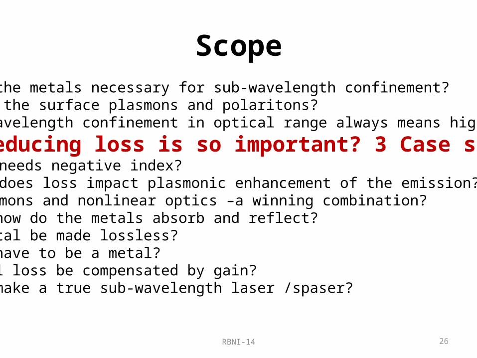
Scope•Why are the metals necessary for sub-wavelength confinement?•What are the surface plasmons and polaritons?•Why subwavelength confinement in optical range always means high loss?•Why reducing loss is so important? 3 Case studies
1. Who needs negative index?2. How does loss impact plasmonic enhancement of the emission?3. Plasmons and nonlinear optics –a winning combination?
•Why and how do the metals absorb and reflect?•Can a metal be made lossless?•Does it have to be a metal?•Can metal loss be compensated by gain?•Can one make a true sub-wavelength laser /spaser?

RBNI-14 5
Scope
•Why are the metals necessary for sub-wavelength confinement?•What are the surface plasmons and polaritons?•Why subwavelength confinement in optical range always means high loss?•Why reducing loss is so important? 3 Case studies
1. Who needs negative index?2. How does loss impact plasmonic enhancement of the emission?3. Plasmons and nonlinear optics –a winning combination?
•Why and how do the metals absorb and reflect?•Can a metal be made lossless?•Does it have to be a metal?•Can metal loss be compensated by gain?•Can one make a true sub-wavelength laser /spaser?
RBNI-14 6
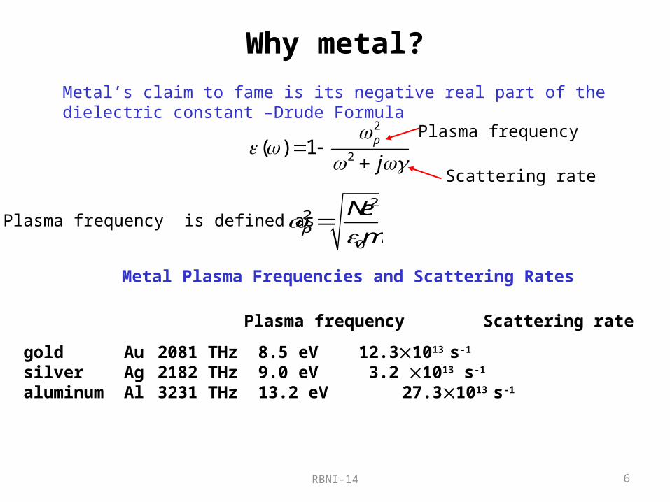
Why metal?Metal’s claim to fame is its negative real part of the dielectric constant –Drude Formula
2
2( ) 1 p
j
22
0p
Ne
m
Plasma frequency is defined as
Metal Plasma Frequencies and Scattering Rates
gold Au 2081 THz 8.5 eV 12.31013 s-1
silver Ag 2182 THz 9.0 eV 3.2 1013 s-1 aluminum Al 3231 THz 13.2 eV 27.31013 s-1
Plasma frequency Scattering rate
Plasma frequency
Scattering rate

RBNI-14 7
Permittivity of Gold
K. Busch et al., Phys. Rep. 444, 101 (2007)
experimental
Drude fit
Interband absorption

RBNI-14 8
Material Q-factor
Re( )
Im( )MQ
Realistically…QM~10-20 because of surface scattering

RBNI-14 9
What does negative mean?
( ) ( ) ( ) ( )n n j
The electrons move to screen the electro-magnetic field – hence the field gets expelled from the metal and the field inside becomes evanescent
MetalFree Electronsx
------------
++++++++++++
Surface Charge
ES Screening field
Total Field=0
EExternal field Refractive index –complex, mostly
imaginary
Evanescent Field
( ) ( )
0 0~ ~j n z zc cE E e E e
z
E

Bulk Charge Oscillations2
2( ) 1 p
j
( ) 0p
In bulk metal when the frequency exceeds plasma frequency the electrons can no longer follow the electric field and screen it – metal becomes transparent
At plasma frequency the bulk metal supports longitudinal charge oscillations
------------
++++++++++++
E
------------
++++++++++++
E
10RBNI-14

RBNI-14 11
Why do we need free carriers?
min ~ / 2L nComes from the uncertainty principle
/ 2p x
/ 2k x
min
21/ 2
nL
min ~ / 4L n
We want to concentrate optical field on sub-wavelength scale…but are prevented by the diffraction limit
To see how we can beat diffraction limit …let us re-derive it from the energy conservation considerations
Easy to understand for real n…but what about imaginary part?

RBNI-14 12
t
E
H =0
nEH E
k
2
2e
EU
Electric “Potential”Energy
2 2
0 2 2M
H EU
Magnetic“Kinetic”Energy
sin( )sin( )kz tE
Ewt=0
al
cos( )cos( )kz tH
Hwt=p/2
al
UMUE
0
2 n nk
c
Energy balance in a mode
Energy oscillates between potential (electric) and kinetic (magnetic)

RBNI-14 13
UM
UE
sin sin( )z ta
E
Ewt=0
a l
cos cos( )z ta
H
Hwt=0
a l
t
E
H =0 0 0
2 2a a na nEH E c E
0 2
2
ca
n n
2
2e
EU
Electric “Potential”Energy
2 22 2
00 0
2 2
2 2M E
H na E naU U
Magnetic“Kinetic”Energy
Lack of energy balance in a sub-l mode
If a<<l0/2n there is almost no magnetic field (quasi-static limit) UM<<UE –energy is not conserved
The energy will radiate because it cannot all fit into magnetic energy –this is diffraction limit!

RBNI-14 14
0 0
2na nEH
0 2
2
ca
n n
2
2e
EU
Electric “Potential”Energy
2
0
2M E
naU U
Magnetic“Kinetic”Energy
Free carriers restore balance in a sub-l mode
sin sin( )z ta
E
Ewt=0
a l
++
+ cos cos( )
cos( )
z ta
t
H
J
Hwt=0
a l
v
J
2 2
2
2 2
~
KK
K E
Nmv L JU
L CU
TrueKinetic”Energy of electrons LK=Kinetic Inductance
(inertia of electrons)
UE UM UK
At some resonant frequency w0 the balance is achieved
If a<<l0/2n there is almost no magnetic field (quasi-static limit) UM<<UE – hence energy oscillates between electric energy and kinetic energy of free carriers

RBNI-14 15
Scope•Why are the metals necessary for sub-wavelength confinement?
•What are the surface plasmons and polaritons?•Why subwavelength confinement in optical range always means high loss?•Why reducing loss is so important? 3 Case studies
1. Who needs negative index?2. How does loss impact plasmonic enhancement of the emission?3. Plasmons and nonlinear optics –a winning combination?
•Why and how do the metals absorb and reflect?•Can a metal be made lossless?•Does it have to be a metal?•Can metal loss be compensated by gain?•Can one make a true sub-wavelength laser /spaser?

Surface charge oscillations
1p
sp
D
d>0
m<0---
+++
+++
+++
---
---
---
+++
+++
+++
---
---
---
+++
+++
+++
---
---
---
+++
+++
+++
---
---
Surface plasmon (SP)
( ) ( ) 0m sp d sp
16RBNI-14
RBNI-14 17
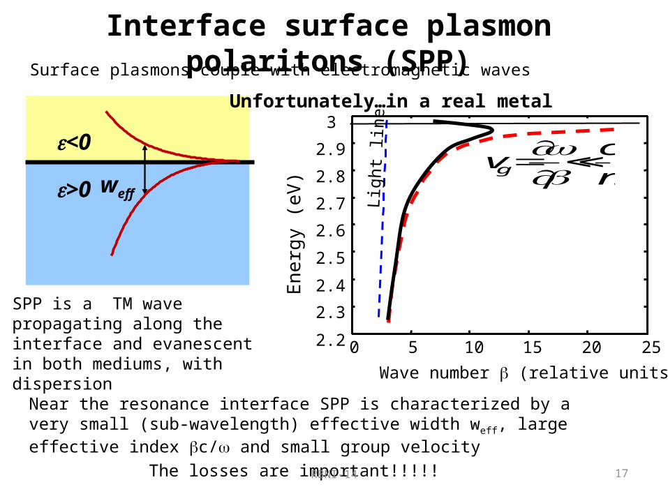
Interface surface plasmon polaritons (SPP)
d mspp
d mc
>0
<0
weff
0 5 10 15 20 252.2
2.3
2.4
2.5
2.6
2.7
2.8
2.9
3
Wave number (relative units)
En
erg
y (e
V)
Ligh
t lin
e
g
cv
n
Unfortunately…in a real metal
Surface plasmons couple with electromagnetic waves
SPP is a TM wave propagating along the interface and evanescent in both mediums, with dispersion
Near the resonance interface SPP is characterized by a very small (sub-wavelength) effective width weff, large effective index c/ and small group velocity
The losses are important!!!!!

RBNI-14 18
Localized SPP of a sub-wavelength nanoparticle
max, 1(cos )
1
l
l l l l
rr aaa
P Er al a
r
+
2 0 For sub-wavelength dimensions one can use electro-static approximation and solve Laplace equation in stead of wave equation
2max,
cos 2
l l
rr a
aaE
ar a
r
Surface charge density oscillations coupled with electric field
0 max,
2 1(cos )
1l l l
lE P
l
Most Important is the Dipole mode l=1
0M
0D
1 1( ) 2 0 2 1
pm D
D
RBNI-14 19
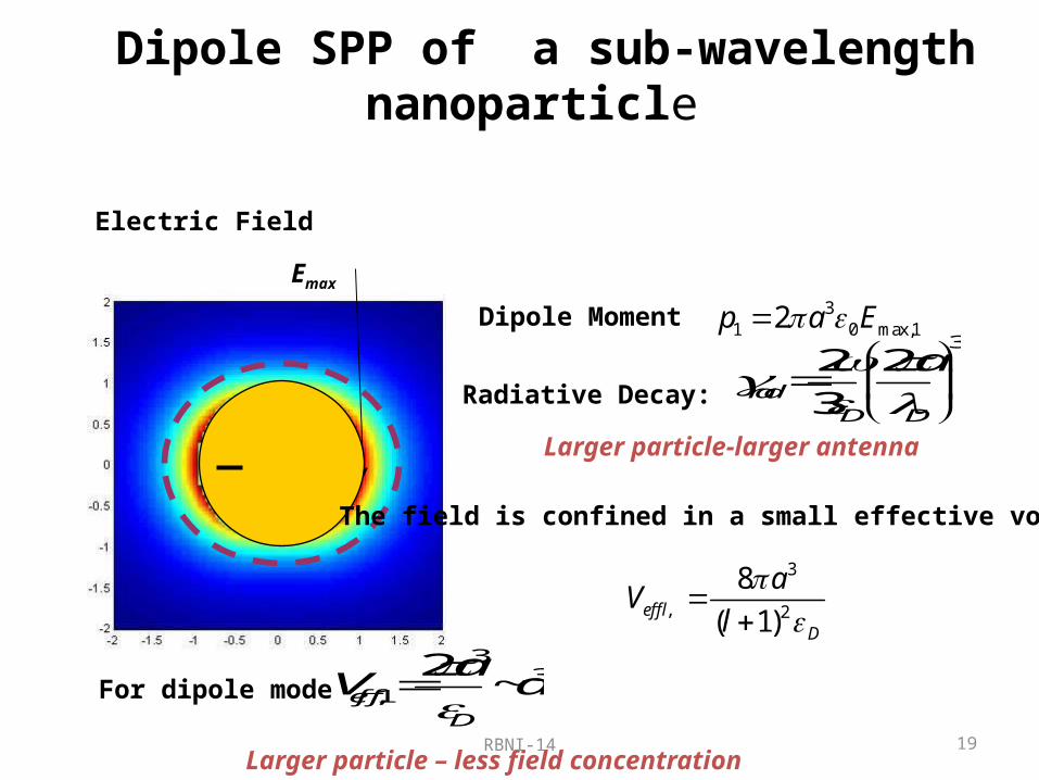
Dipole SPP of a sub-wavelength nanoparticle
Electric Field
31 0 max,12p a E Dipole Moment
Larger particle-larger antenna
Emax
+
3
, 2
8
( 1)eff lD
aV
l
Larger particle – less field concentration
For dipole mode3
3,1
2~eff
D
aV a
Radiative Decay:
32 2
3radD D
a
The field is confined in a small effective volume !

RBNI-14 20
Scope•Why are the metals necessary for sub-wavelength confinement?•What are the surface plasmons and polaritons?
•Why does subwavelength confinement in optical range always means high loss?•Why reducing loss is so important? 3 Case studies
1. Who needs negative index?2. How does loss impact plasmonic enhancement of the emission?3. Plasmons and nonlinear optics –a winning combination?
•Why and how do the metals absorb and reflect?•Can a metal be made lossless?•Does it have to be a metal?•Can metal loss be compensated by gain?•Can one make a true sub-wavelength laser /spaser?

RBNI-14 21
The heavy price of having free carriers
wt=p/2J In the sub-wavelength metallic structures (in all three
dimensions !) half of the time almost all the energy is stored in kinetic motion of electrons –where it is being lost with the decay rate 2 of the order of 10 fs-1. Therefore the rate of energy loss in truly sub-wavelength structure ,geff, is always of the order of .
Case of propagating SPPHere sub-wavelength simply means very large wave-vector
0 5 10 15 20 252.2
2.3
2.4
2.5
2.6
2.7
2.8
2.9
3
Wave number (relative units)
Ene
rgy
(eV
)
g
cv
n
Long Range SPP
High Loss in “true plasmon” region
RBNI-14 22
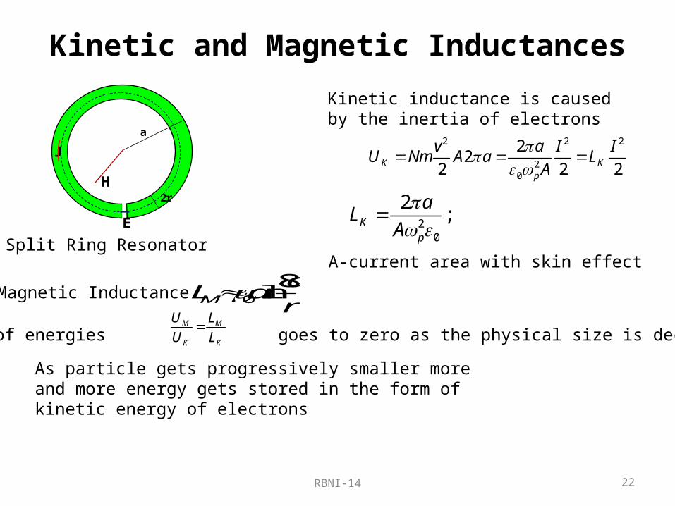
Kinetic and Magnetic Inductances
2 2 2
20
22
2 2 2K Kp
v a I IU Nm A a L
A
20
2; K
p
aL
A
Magnetic Inductance 0
8lnM
aL a
r
The ratio of energies goes to zero as the physical size is decreasedM M
K K
U L
U L
As particle gets progressively smaller more and more energy gets stored in the form of kinetic energy of electrons
Kinetic inductance is caused by the inertia of electrons
2r
a
J
E
H
Split Ring ResonatorA-current area with skin effect
RBNI-14 23
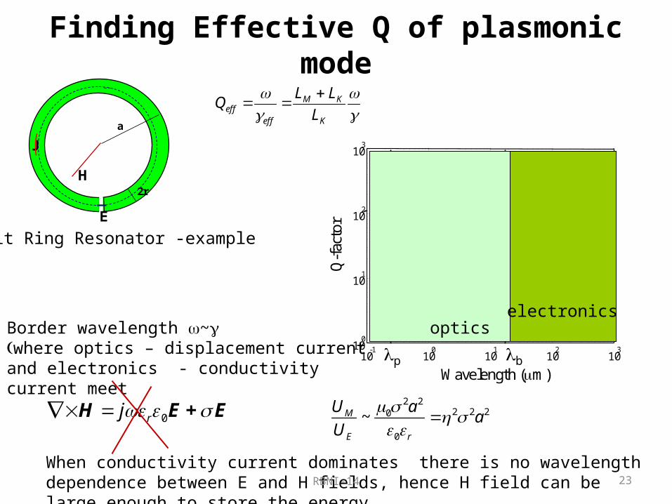
Finding Effective Q of plasmonic mode
M Keff
eff K
L LQ
L
2r
a
J
E
H
Split Ring Resonator -example
10-1
100
101
102
10310
0
101
102
103
2a=/4
/8
/16/32
Wavelength (m)
Q-f
acto
rp b
Qm0
a=4r
Au
Border wavelength w~ g(where optics – displacement current and electronics - conductivity current meet
opticselectronics
0rj H E + E2 2
2 2 20
0
~M
E r
U aa
U
When conductivity current dominates there is no wavelength dependence between E and H fields, hence H field can be large enough to store the energy

RBNI-14 24
Estimate of effective loss
Q of Drude metal structure actually gets reduced with wavelength and only starts getting better when < - THz region which is not really optics –and even then LC circuit is not a very high Q resonator!!!!!
That is why high Q resonators in electronics include:low loss inductances with high (energy stored in spin magnetization and not kinetic energy of electrons)Quartz crystalsSurface acoustic waves/2 cavities ….
The true sub-wavelength region where kinetic inductance dominates (plasmonics) is inherently lossy and various geometric tricks will not mitigate this loss significantly!
optics
electronics
100
101
10210-4
10-3
10-2
10-1
100
101
102
2a=/4
/8/16/32
Wavelength (m)b
eff
()/
(b)

RBNI-14 25
Plasmonic and loss are inseparable
Frequency (n/l)
Confinement (1/a)
/a n
/a n /a n
1/100nm1/50mm
p
/a n
/a n
Conductivity currentFree carriersELECTRONICS
Conductivity currentBound carriersAbsorber
Reactivecurrent, free carriersPLASMONICS
Reactive (Displacement) current, bound carriersOPTICS
Reactive current of free carriers can be confined on sub wavelength scale but then it cannot engender magnetic field strong enough to store the energy without excessive loss
RBNI-14 26
Scope•Why are the metals necessary for sub-wavelength confinement?•What are the surface plasmons and polaritons?•Why subwavelength confinement in optical range always means high loss?
•Why reducing loss is so important? 3 Case studies1. Who needs negative index?2. How does loss impact plasmonic enhancement of the emission?3. Plasmons and nonlinear optics –a winning combination?
•Why and how do the metals absorb and reflect?•Can a metal be made lossless?•Does it have to be a metal?•Can metal loss be compensated by gain?•Can one make a true sub-wavelength laser /spaser?
RBNI-14 27
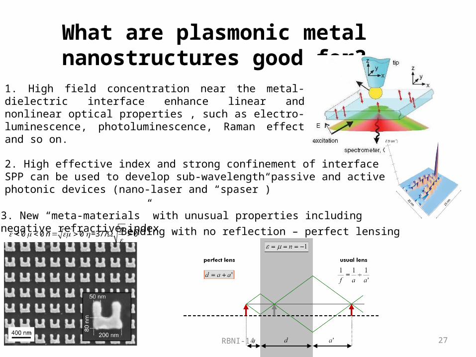
What are plasmonic metal nanostructures good for?
1. High field concentration near the metal-dielectric interface enhance linear and nonlinear optical properties , such as electro-luminescence, photoluminescence, Raman effect and so on.
3. New “meta-materials” with unusual properties including negative refractive index
0 0 0 =377 0n
Bending with no reflection – perfect lensing
2. High effective index and strong confinement of interface SPP can be used to develop sub-wavelength passive and active photonic devices (nano-laser and “spaser”)

RBNI-14 28
Why do we need negative index material?
Presumably to get to the super-resolution……-Pendry’s superlens.
nn
object image
-n2
21 p
Perfect near field focus
But we know that the moment we introduce finite loss in the metal g, the resolving power of this near field lens deteriorates drastically
2
21 p
j
0
50
100
150
-150
-100
-50
0 10 20 30
X(nm))
Z(nm
)
Case study 1: Who needs negative index?

RBNI-14 29
What if we reduce (or eliminate) loss?Create “artificial dielectric” with metal nanoparticles playing the role of atoms with large polarizability
20
2 2 2 20 0(1 / )eff d d
Qf f
j Q j
2 20 /p K Resonant frequency (K=3 for spheres)
f-filling fraction /Q
Near the resonance we can get fairly large values of
Then we can just make a conventional lens with high resolution l/neff that would give us a magnified image in the far field
1/2 1/2~ ~eff effn Q

RBNI-14 30
What does it mean?
-1Loss(s )
1
2
3
4
x 1013
6 3 1 0.2
superlens
metal - dielectric composite lens
Silver
nn
object image
-n
With the current high metal loss the Superlens does not really perform
If the loss is reduced one can get higher resolution and magnified image in far field without negative n!
Reduced loss would change everything!

RBNI-14 31
Meta-Catch 22
As long as metal loss stays what it is, negative index materials in optical range are highly unfeasible
If one could reduce metal loss by an order of magnitude or more the negative index materials and devices may become highly unnecessary
Probably makes sense to see what we can do about loss
A catch-22 is a paradoxical situation in which an individual cannot avoid a problem because of contradictory constraints or rules. Often these situations are such that solving one part of a problem only creates another problem, which ultimately leads back to the original problem.

RBNI-14 32
Case study 2: how loss impacts plasmonic enhancement of emission, absorption, Raman….
RBNI-14 33
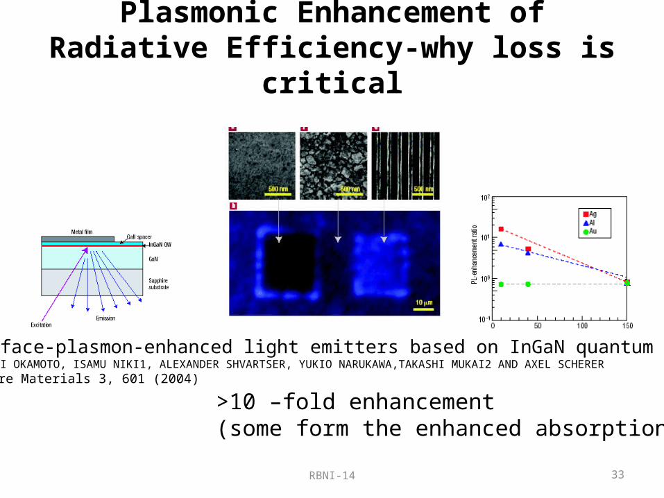
Plasmonic Enhancement of Radiative Efficiency-why loss is critical
Surface-plasmon-enhanced light emitters based on InGaN quantum wellsKOICHI OKAMOTO, ISAMU NIKI1, ALEXANDER SHVARTSER, YUKIO NARUKAWA,TAKASHI MUKAI2 AND AXEL SCHERERNature Materials 3, 601 (2004)
>10 –fold enhancement(some form the enhanced absorption)

RBNI-14 34
Origin of plasmonic enhancement
Radiative decay is proportional to the density of states
3 2
3 2 3 3
4D
n
c
About 1/THz.m3 @400nm
Radiative time even for the allowed transition~100ps
21 3 3 2
3 30 0
5 10 /2rad D D
e ff m ps
m
Oscillator strength
Nonradiative time can be much shorter…because density of final states is orders of magnitude higher
1 33
4~ ~D
nrad phononph ph
radnrad
nrad
nradrad
radrad
11
1
RBNI-14 35
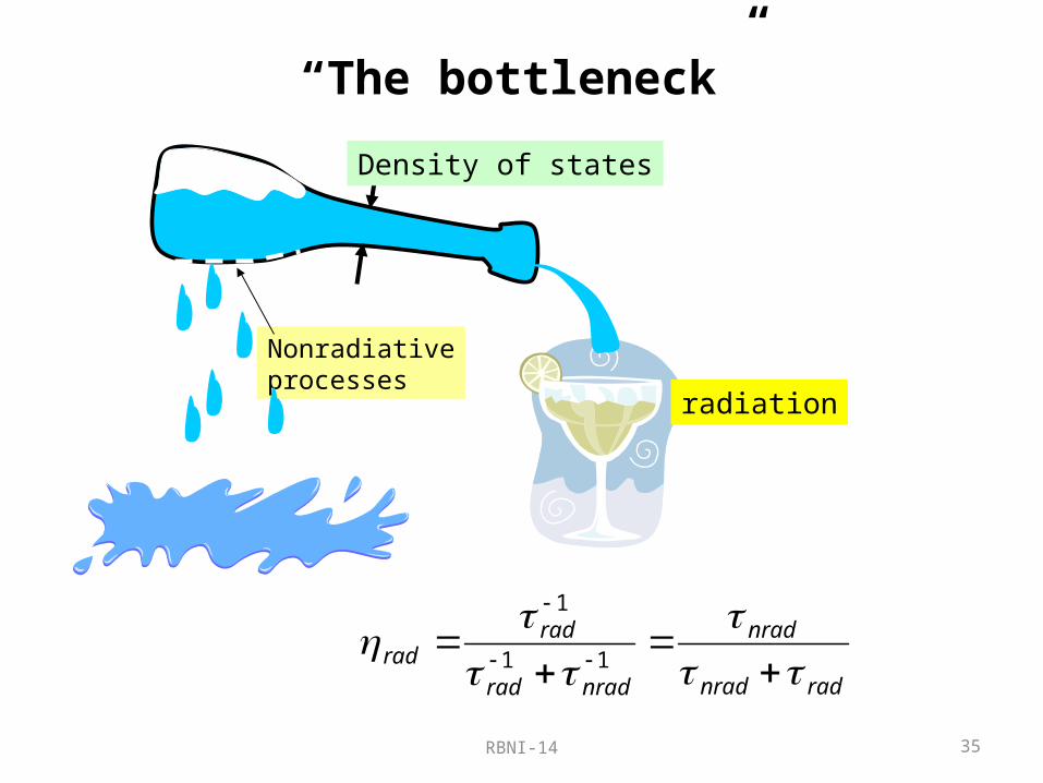
“The bottleneck”
Density of states
Nonradiativeprocesses
radiation
radnrad
nrad
nradrad
radrad
11
1
RBNI-14 36
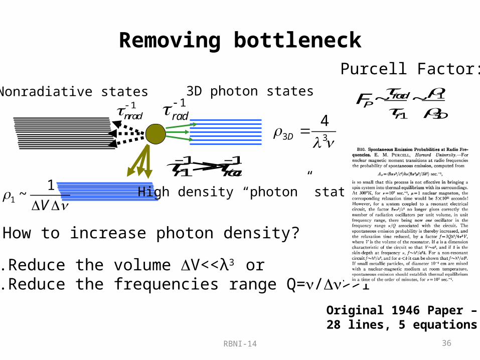
Removing bottleneck
3D photon statesNonradiative states1
nrad 1rad
High density “photon” states
1 11r rad
How to increase photon density?
1. Reduce the volume V<<λ3 or2. Reduce the frequencies range Q=/>>1
3 3
4D
1
1~
V
Purcell Factor:1
1 3
~ ~radP
r D
F
Original 1946 Paper –28 lines, 5 equations
RBNI-14 37
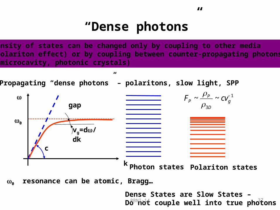
“Dense photons”Density of states can be changed only by coupling to other media(polariton effect) or by coupling between counter-propagating photons (microcavity, photonic crystals)
Propagating “dense photons” – polaritons, slow light, SPP
0
k
c
Photon states
0 resonance can be atomic, Bragg…
gap
vg=d/dk
Polariton states
Dense States are Slow States –Do not couple well into true photons
1
3
~ ~PP g
D
F cv

RBNI-14 38
“Dense photons II”Density of states can be changed only by coupling to other media(polariton effect) or by coupling between counter-propagating photons (microcavity, photonic crystals)
Localized “dense photons” – microcavity, localized SP
Dense States are ConfinedDo not couple well into true photons
Free photon statesn-cavity resonance
Veff
3
3
~ ~cavP
D eff
FV

RBNI-14 39
Re-emergence of the bottleneck
3D photon statesNonradiative states1
nrad 1rad
“dense photons”
1 11r P radF
3 3
4D
1
1~
V
radTransfer from “dense” (high impedance) to normal (low impedance) photons
More nonradiative states
nradNonradiative decay of “dense photons”

RBNI-14 40
The bottleneck is alive and well…just shifted down the line
Density of states
Nonradiativeprocesses
radiation
Reservoir of dense photons
Nonradiativeprocesses
radiation
rad
nrad
Nonradiative decay
RBNI-14 41
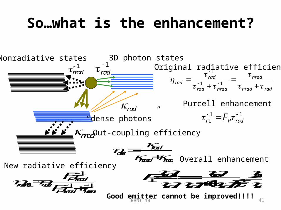
So…what is the enhancement?
3D photon statesNonradiative states1
nrad 1rad
“dense photons” rad
nrad
radnrad
nrad
nradrad
radrad
11
1Original radiative efficiency
1 11r P radF
Purcell enhancement
radout
nrad rad
Out-coupling efficiency
New radiative efficiency1
,1 1 1P rad
rad outP rad nrad
F
F
Overall enhancement
,11 1(1 )
rad out out
rad rad rad P rad
FF
Good emitter cannot be improved!!!!
RBNI-14 42
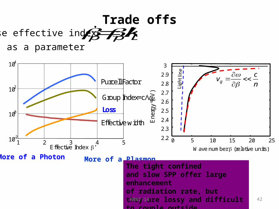
Trade offsUse effective index ' /p p Dk
as a parameter
More of a PlasmonMore of a PhotonThe tight confinedand slow SPP offer large enhancementof radiation rate, butthey are lossy and difficult to couple outside
0 5 10 15 20 252.2
2.3
2.4
2.5
2.6
2.7
2.8
2.9
3
Wave number (relative units)E
nerg
y (e
V)
g
cv
n
1 2 3 4 510-2
100
102
104
Effective Index ’
Purcell Factor
Group Index=c/vg
Effective width
Loss

RBNI-14 43
Main result for Propagating Interface SPPF 1
Substantial improvement can be achieved only for very inefficient emitters with rad<1%

RBNI-14 44
Enhancement with localized SPP
+
31 0 max,12p a E Dipole Moment
Larger particle-better antenna
Effective Volume3
effD
aV
Smaller particle – better resonator
It is easy to see that the same particle cannot be a good antenna and a good resonator at once!
Only the emitters whose efficiency is originally quite poor can be significantly enhanced by SPP
Similarly, when it comes to absorption only very weak absorbers can be enhanced by SPP
Maximum possible enhancement is on the order of
rad nrad
Q
RBNI-14 45
Case study 3: Plasmons and nonlinear optics
RBNI-14 46
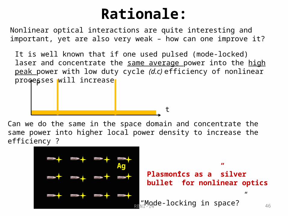
Rationale:Nonlinear optical interactions are quite interesting and important, yet are also very weak – how can one improve it?
Ag
It is well known that if one used pulsed (mode-locked) laser and concentrate the same average power into the high peak power with low duty cycle (d.c) efficiency of nonlinear processes will increase
t
P
Can we do the same in the space domain and concentrate the same power into higher local power density to increase the efficiency ?
Plasmonics as a ”silver bullet” for nonlinear optics
“Mode-locking in space?”

RBNI-14
+-
++
+
-
--
+-
++
+
-
--
+-
++
+
-
--
+- +-
Plasmonic concentrators
47
22 2 3~ ~ 10 10localE
QE
24 4 5~ ~ 10 10localE
QE
M. Stockman, P. Nordlander
+-
++
+
-
--
2
2( ) 1 p
j
But:
Plasmonic concentration always brings loss
~ ~ ~ 10 20r
i
Q
RBNI-14 48
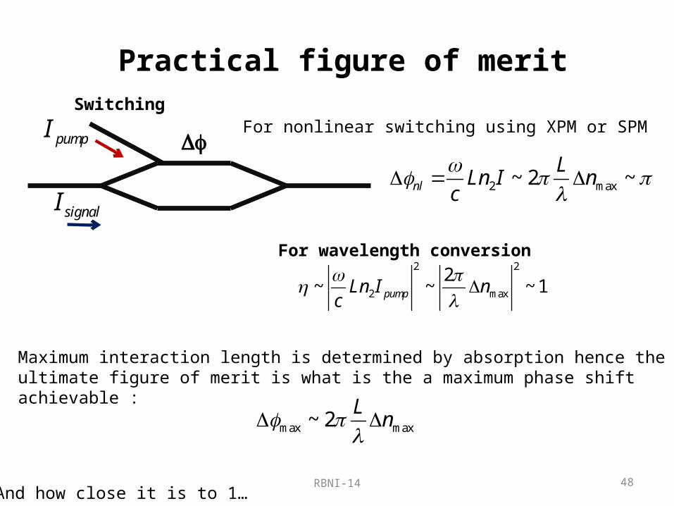
Practical figure of merit
Df
Switching
pumpI
signalI
For nonlinear switching using XPM or SPM
2 max~ 2 ~nl
LLn I n
c
For wavelength conversion2 2
2 max
2~ ~ ~ 1pumpLn I n
c
Maximum interaction length is determined by absorption hence the ultimate figure of merit is what is the a maximum phase shift achievable :
max max~ 2L
n
And how close it is to 1…

RBNI-14 49
Enhancing nonlinear index
Ag Ag
Ag
Ag Ag
Ag
Ag
Ag
c(3)pumpI
sigI
pumpE
sigE
f
f – volume filling factor k– mode overlap

RBNI-14 50
Assessing nonlinearity enhancement (3)
4 3(3)
~ 12 ~ 10eff f Q
This sounds mighty good…..
What about absorption?2
3deff
nfQ
Maximum phase shift
2, 4
2
~ 12effnf Q
n
3max 2, 2
2~ 4eff
eff
n I Q n I
Enhanced as much as few hundreds times This sounds really good…..except
still, assuming 13 22 10 /n cm W (chalcogenide glass)
10,max 10nl I
indicating that the input pump pump density must be in excess of 10GW/cm2 in order to attain switching or efficient frequency conversion, meaning that while the length of the device can get reduced manyfold, the switching power cannot and remains huge….
Local “intensity” is now in excess of 1000 GW/cm2 –way past break down!
and the things only go further downhill from here on once it is realized that all of the enhancement is achieved because the pump field is really concentrated by a factor of Q2
>100!

RBNI-14 51
Saturation of nonlinearityEven if one disregards optical damage nonlinear index change saturates
Borchers et al, “Saturation of the all-optical Kerr effect in solids”, Opt Lett 37, 1541 (2012)So, what is the real limit?

RBNI-14 52
A slightly better figure of merit24 (3)
, 0~ 12sig nl pump sigf Q P E E
206 local sigf Q n E
Assuming that maximum index change is limited by material properties to max 0.01localn n
2,max max max
2~ 3 0.01nl
eff
f Q n Q n
the maximum phase shift is…
The path to achieve either all-optical switching or efficient frequency conversion is less than obvious
Factor of Q2 makes perfect sense –because SPP mode is a harmonic oscillator with a given Q –changing local index shifts resonant frequency and causes change in polarizability proportional to Q2
0
,Re( )sig nlp
0

RBNI-14 53
10-5
10-4
10-3
10-2
10-1
10010
-6
10-5
10-4
10-3
10-2
10-1
100
Phas
e Sh
ift (r
ad) f=10-3
f=10-4
f=10-5
f=10-6
Length (cm)
1mm2 13 2
2 10 /n cm W
P=1W1mm2
13 22 10 /n cm W
P=1W
Phase shift vs. distance

RBNI-14 54
Two ways to define figure of meritScientific approach
Engineering approach What would be the overall maximum attainable result at ~one absorption length?
For the nonlinear index type process – what is the maximum phase shift attainable at 10dB loss?
What is the maximum attainable enhancement of nonlinear susceptibility?
For c(2) enhancement is kfQ3 ~102-103
For c(3) enhancement is kfQ6 ~105-106
DFmax~kQDnmax~10-2<<p
Not enough for all-optical switch(or frequency conversion)
+- +++-
--+
- +++-
--
+- +++-
--+- +-

RBNI-14 55
Why such a conflicting result ?
Scientific approach: what matters is the relative improvement
Engineering approach: what matters is the end result
Take very weak process with efficiency approaching 0….then if the end result is <<1
a very large powerResult= 10
0
a very large powerResult = 0 × 10 << 1
Using metal nanoparticles for enhancement of second order nonlinear processes may not be a “silver bullet” we are looking for.
Ag
Plasmonic enhancement is an excellent technique for study of nonlinear optical properties (the higher order the better) and sensing using it, but it perhaps less stellar for any type efficient switching, conversion, gating etc.

RBNI-14 56
Scope•Why are the metals necessary for sub-wavelength confinement?•What are the surface plasmons and polaritons?•Why subwavelength confinement in optical range always means high loss?•Why reducing loss is so important? 3 Case studies
1. Who needs negative index?2. How does loss impact plasmonic enhancement of the emission?3. Plasmons and nonlinear optics –a winning combination?
•Why and how do the metals absorb and reflect?•Can a metal be made lossless?•Does it have to be a metal?•Can metal loss be compensated by gain?•Can one make a true sub-wavelength laser /spaser?
RBNI-14 57
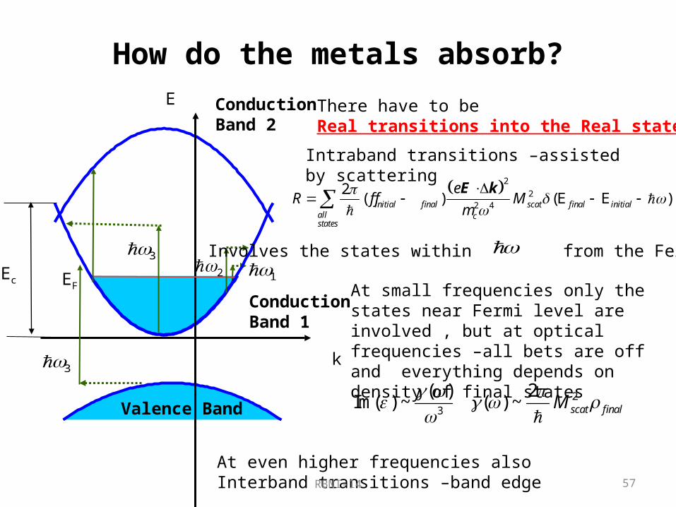
How do the metals absorb?
EF
Valence Band
1
Conduction Band 1
Conduction Band 2
k
E
Ec2
3
3
Intraband transitions –assisted by scattering
2
22 4
2( ) (E E )initial final scat final initial
all cstates
eR f f M
m
E k
At even higher frequencies also Interband transitions –band edge
There have to be Real transitions into the Real states
Involves the states within from the Fermi level
23
( ) 2Im( ) ~ ( ) ~ scat finalM
At small frequencies only the states near Fermi level are involved , but at optical frequencies –all bets are off and everything depends on density of final states

RBNI-14 58
Why are the metals lossier than Semiconductors?
EF
Valence Band
k
E
Metal
EF
Valence Band
Semiconductor
k
E
~ finalR r
E
,final met
,final sem
Density of final states is much higher in the metalsOf course plasma frequency is higher in metals, hence trade–off is inevitable, but semiconductor is a viable alternative in the THz regime

RBNI-14 59
Why at optical frequencies loss does not decrease dramatically with temperature?
Valence Band
k
ETo maintain energy conservation phonons must be involved
To maintain momentum conservationPhonons must have wave vector commensurate with the Fermi wave vector
kF
For low frequencies only absorption of phonons is possible – this process is proportional to the number of phonons and thus highly temperature dependent
EF
( )
~ 1 5
ph Fk
THz
ph
( )ph Fk ph
For high frequencies both absorption and emission of phonons is possible – the later process has a spontaneous component that does not depend on phonon number and thus is temperature independent

RBNI-14 60
Temperature independent absorption with e-e- scattering
2( ) ~ /ee FE
k
E
EF
k1
k2
k3
Hee h
(a) (b)
k
E
EF
k1
k2
k3
k4Hee
h
k
E
EF
k1
k2
k3
k4
Hee
h
(c)
k
E
EF
k1
k2
k3
k4
Hee
h
(d)
Two electrons are excited by a single photon
Only Umklapp scattering is contributing
3 1 4 2 k k k k g
The process becomes very important at high frequencies
RBNI-14 61
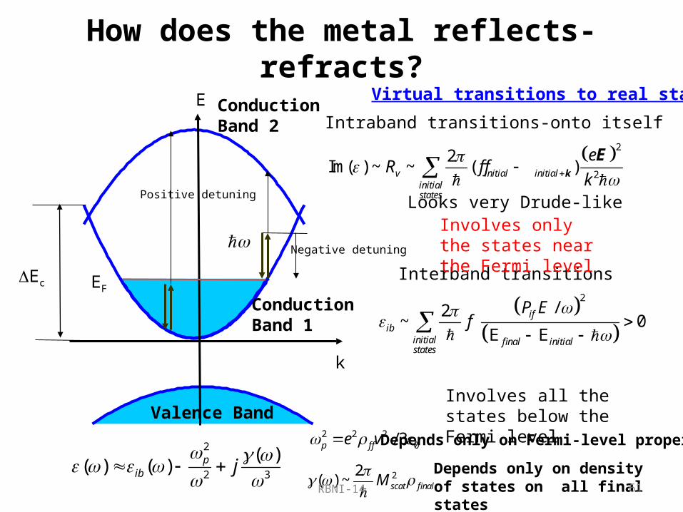
How does the metal reflects-refracts?
EF
Valence Band
Conduction Band 1
Conduction Band 2
k
E
Ec
Intraband transitions-onto itself
2
2
2Im( ) ~ ~ ( )v initial initial
initialstates
eR f f
k
k
E
Looks very Drude-like
Interband transitions
Virtual transitions to real states
Negative detuning
Positive detuning
2/2
~ 0E E
if
ibinitial final initialstates
P Ef
Involves only the states near the Fermi level
Involves all the states below the Fermi level
2
2 3
( )( ) ( ) p
ib j
2 2 20/ 3p f fe v Depends only on Fermi-level properties
22( ) ~ scat finalM
Depends only on density of states on all final states

RBNI-14 62
Scope•Why are the metals necessary for sub-wavelength confinement?•What are the surface plasmons and polaritons?•Why subwavelength confinement in optical range always means high loss?•Why reducing loss is so important? 3 Case studies
1. Who needs negative index?2. How does loss impact plasmonic enhancement of the emission?3. Plasmons and nonlinear optics –a winning combination?
•Why and how do the metals absorb and reflect?
•Can a metal be made lossless?•Does it have to be a metal?•Can metal loss be compensated by gain?•Can one make a true sub-wavelength laser /spaser?
RBNI-14 63
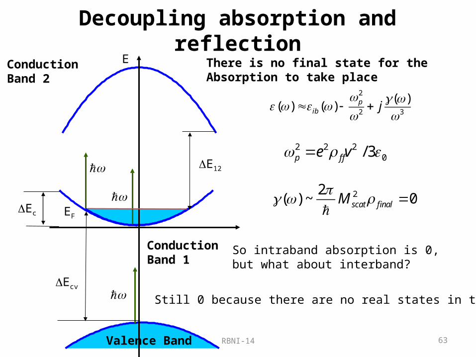
Decoupling absorption and reflection
22( ) ~ 0scat finalM
Valence Band
Conduction Band 2
EF
E
Ec
E12
Ecv
Conduction Band 1
There is no final state for the Absorption to take place
2 2 20/ 3p f fe v
2
2 3
( )( ) ( ) p
ib j
So intraband absorption is 0, but what about interband?
Still 0 because there are no real states in the gap

RBNI-14 64
Lossless, yet metal?
Valence Band
Conduction Band 2
EF
E
Ec
E12
Ecv
Conduction Band 1
There is no final state for the absorption to take place
12,c cvE E E
2
2( ) ( ) p
ib
2 2 2 2
0/ 3p f fe v
But we still want negative e
Thus we want narrow bands with wide gaps
We need large Fermi velocity (small effective mass)
As always in Nature we see two contradictory demands and thus should see if some type of trade-off and compromise is possible

RBNI-14 65
Consider b.c.c. lattice (Na)
a
Vss
Coupling strength Vss
Brillouin Zone –f.c.c.
EFEc
Tight Binding Model
RBNI-14 66
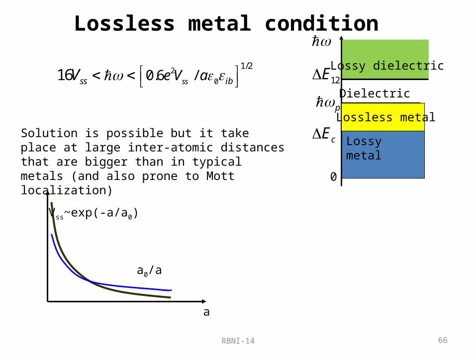
Lossless metal condition
2
0
1/20.6 /16 ssss ibe V aV
a
Vss~exp(-a/a0)
a0/a
Solution is possible but it take place at large inter-atomic distances that are bigger than in typical metals (and also prone to Mott localization)
Lossy metal
p
cE
0
Lossless metal
Dielectric
Lossy dielectric12E

RBNI-14 67
Example:Na
2 4 6 8 10 12 14-10
-9
-8
-7
-6
-5
-4
-3
-2
-1
0
Ener
gy (e
V)
Lattice Constant (A)
3s
3p
Ec
E12Ef
Need Lattice constant of 8 Angstrom instead of 4.3 Angstrom
That is why metals absorb….
RBNI-14 68
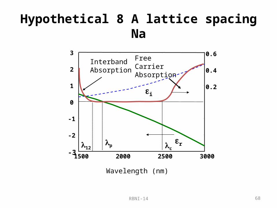
Hypothetical 8 A lattice spacing Na
1500 2000 2500 3000-3
-2
-1
0
1
2
3
Wavelength (nm)
FreeCarrierAbsorption
r
InterbandAbsorption
i
p c12
0.2
0.4
0.6
RBNI-14 6969
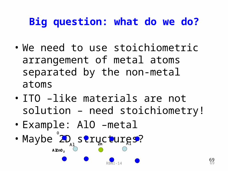
Big question: what do we do?
• We need to use stoichiometric arrangement of metal atoms separated by the non-metal atoms
• ITO –like materials are not solution – need stoichiometry!
• Example: AlO –metal • Maybe 2D structures?
AlZnO2
Al AlZn
O
AlZnO2
Al AlZn
O
RBNI-14 7070
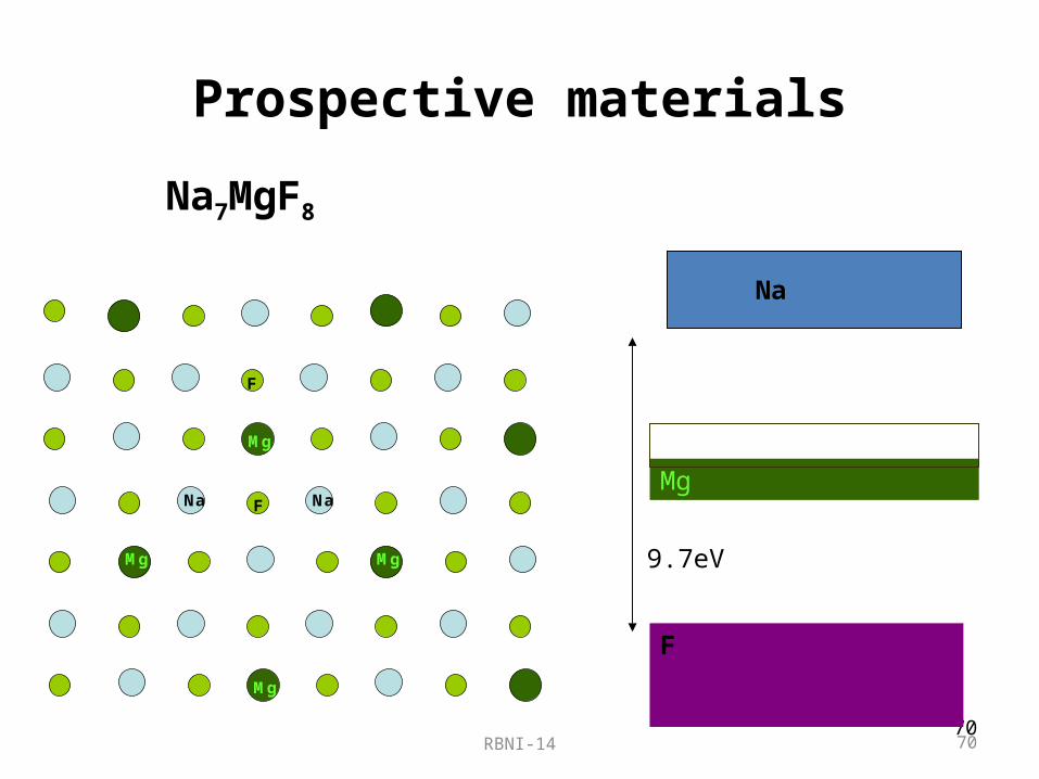
Prospective materials
Na7MgF8
Mg
Na
F
Mg
Mg
Mg
NaF
Na
F
Mg
9.7eV

RBNI-14 71
Scope•Why are the metals necessary for sub-wavelength confinement?•What are the surface plasmons and polaritons?•Why subwavelength confinement in optical range always means high loss?•Why reducing loss is so important? 3 Case studies
1. Who needs negative index?2. How does loss impact plasmonic enhancement of the emission?3. Plasmons and nonlinear optics –a winning combination?
•Why and how do the metals absorb and reflect?•Can a metal be made lossless?
•Does it have to be a metal?•Can metal loss be compensated by gain?•Can one make a true sub-wavelength laser /spaser?

RBNI-14 72
Potential and Kinetic energy of the oscillator
2202
d r dr er E
dt dt m
Equation of motion0
0 2 20
/( )
e mr
j
Amplitude2
02 20
/( ) 1
Ne m
j
Dielectric constant
22 20 0 2 2 0
0 0 22 2 2 20
1 /
4 4P
Nm r Ne mU E
Potential Energy of electrons Kinetic Energy of electrons
22 20 2 2 0
0 22 2 2 20
1 /
4 4K
Nm r Ne mU E
Far from resonance 0 2
2 00 2
0
1 /
4P
Ne mU E
0KU 2
020
/( ) 1
Ne m
Electric field Energy
2 2 20 02 2
0 0 22 2 2 20
/1 11
4 4E V P K
Ne mU E E U U U
20
1
4VU E
“Pure” Electric field Energy
22 0
0 20
1 /1
4E V P
Ne mU E U U
All of the electric energy is potential
UV
UMUP
00
RBNI-14 73
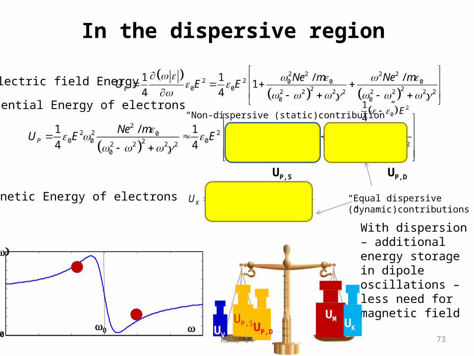
In the dispersive region
Electric field Energy
2 2 2 22 2 0 0 0
0 0 2 22 2 2 2 2 2 2 20 0
1 1 / /1
4 4E
Ne m Ne mU E E
2 2 2 2
2 2 20 0 00 0 02 222 2 2 2 2 2 2 22 2 2 2
0 00
1 / 1 / /
4 4P
Ne m Ne m Ne mU E E
Potential Energy of electrons
Kinetic Energy of electrons
22 2 0
0 22 2 2 20
1 /
4K
Ne mU E
20
1
4E “Non-dispersive (static)contribution”
“Equal dispersive (dynamic)contributions”
UV
UMUP,S
With dispersion – additional energy storage in dipole oscillations –less need for magnetic field
UP,DUK
UP,S UP,D
00
RBNI-14 74
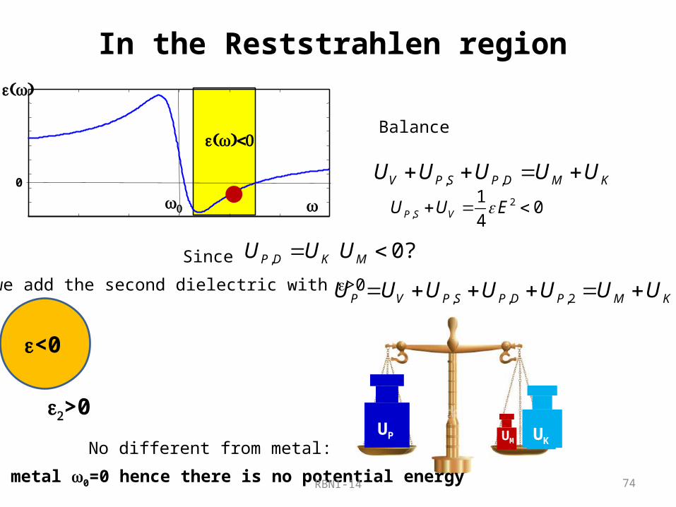
In the Reststrahlen region
2,
10
4P S VU U E
, ,V P S P D M KU U U U U
Balance
0
0
0
,P D KU USince 0?MU If we add the second dielectric with e>0
e<0
e2>0
, , ,2P V P S P D P M KU U U U U U U
UP UM UKNo different from metal:
In metal w0=0 hence there is no potential energy

RBNI-14 75
Improvement?What if we use dielectric, such as SiC in Reststrahlen region (10-12 microns)
The width of SPP resonance geff~g gets reduced relative to the metal as it depends on QM1
2 2
2 21 LO TO
TO j
1MQ
2
Re( )2
Im( )TO
MQ
>0
<0
SiC
SiO2TO
LO
Interface phonon polariton decay constant g is a few ps!!!! (not 10fs as in metal)
It means that phonon polariton decays in time slower than plasmon polariton
e<0
e>0
But the propagation length depends on QM2< QM1 hence the propagation length is not much longer(slow light effect) 1/prop effL d d Similarly, field enhancement is proportional to QM2< QM1 hence it is not as high as in metals
2~ /U E Purcell effect is weak
RBNI-14 76
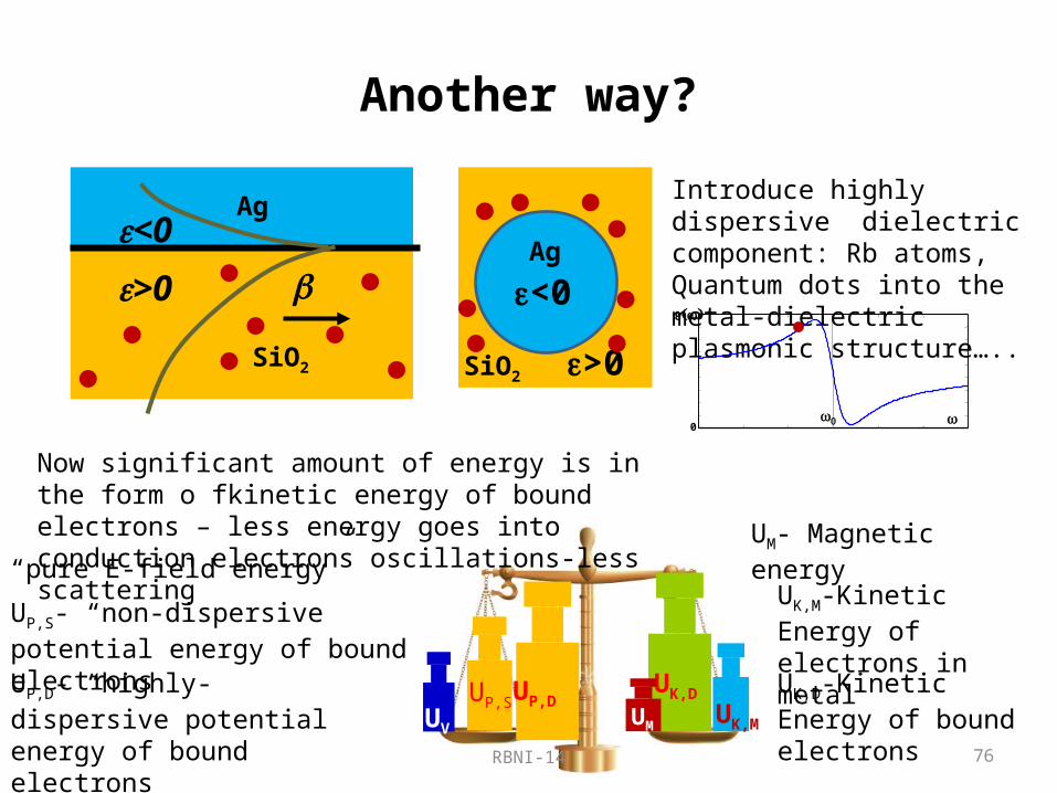
Another way?
>0
<0
Ag
SiO2
e<0
e>0 SiO2
Ag
Introduce highly dispersive dielectric component: Rb atoms, Quantum dots into the metal-dielectric plasmonic structure…..
00
Now significant amount of energy is in the form o fkinetic energy of bound electrons – less energy goes into conduction electrons oscillations-less scattering
UV
UP,S UP,DUK,M
UV- “pure E-field energy”
UP,S- “non-dispersive potential energy of bound electronsUP,D- “highly-dispersive potential energy of bound electrons
UM- Magnetic energy
UK,M-Kinetic Energy of electrons in metal
UK,D-Kinetic Energy of bound electrons
UM
UK,D
UM

RBNI-14 77
“Slow-light loaded plasmon poariton”
Most Energy is contained in the oscillations of bound electrons in dielectric – less in the oscillations of conduction electrons in the metal
The width of SPP resonance geff gets reduced relative to the metal
It means that SL loaded SPP decays in time slower than SPP with non-dispersive dielectric
But the propagation length does not change at all in SL loaded SPP (slow light effect)
1/prop effL d d
Similarly, field enhancement is SL-loaded SPP is no better than in normal SPP
2~ /U E

RBNI-14 78
Can metal loss be compensated by gain?

RBNI-14 79
Scope•Why are the metals necessary for sub-wavelength confinement?•What are the surface plasmons and polaritons?•Why subwavelength confinement in optical range always means high loss?•Why reducing loss is so important? 3 Case studies
1. Who needs negative index?2. How does loss impact plasmonic enhancement of the emission?3. Plasmons and nonlinear optics –a winning combination?
•Why and how do the metals absorb and reflect?•Can a metal be made lossless?•Does it have to be a metal?
•Can metal loss be compensated by gain?•Can one make a true sub-wavelength laser /spaser?
RBNI-14 80
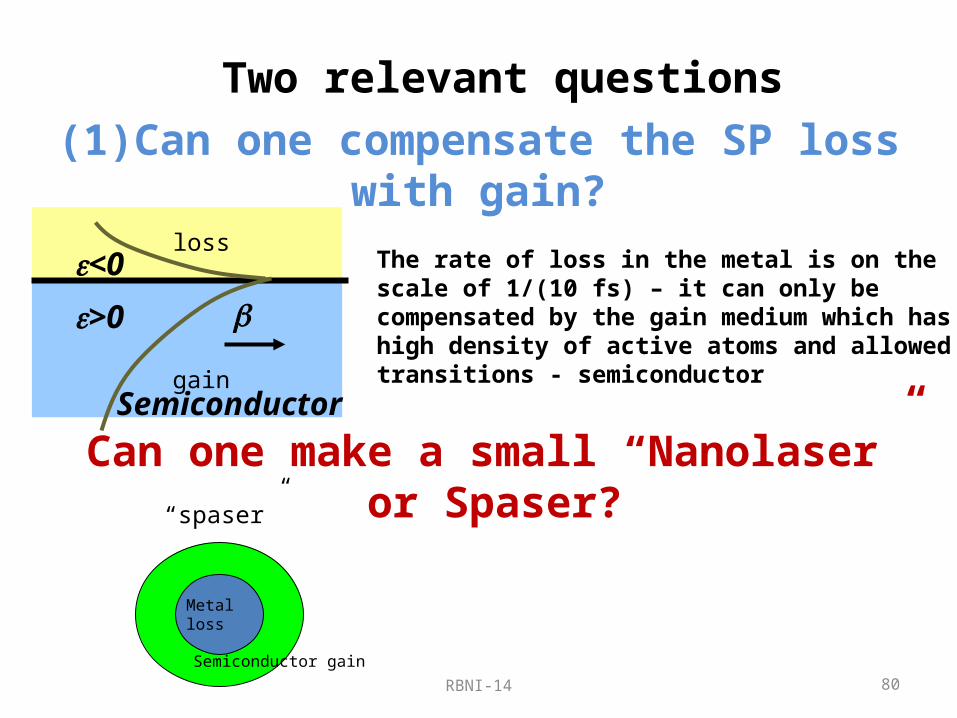
(1)Can one compensate the SP loss with gain?
The rate of loss in the metal is on the scale of 1/(10 fs) – it can only be compensated by the gain medium which has high density of active atoms and allowed transitions - semiconductor
>0
<0
Semiconductor
loss
gain
Metal loss
Semiconductor gain
“spaser”Can one make a small “Nanolaser” or Spaser?
Two relevant questions
RBNI-14 81
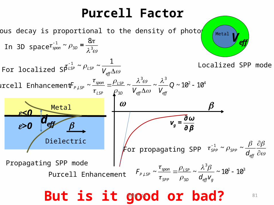
Purcell FactorSpontaneous decay is proportional to the density of photon states
w
∂∂g
ωv =
β
Metal
Localized SPP mode
effV1
3 3
8~spon D
=In 3D space
For propagating SPP 1 ~ ~SPP SPP
effd
Purcell Enhancement3 3
2 4,
3
~ ~ ~ ~ 10 10spon LSPP LSP
LSP D eff eff
F QV V
For localized SP 1 1
~ ~LSP LSPeffV
Purcell Enhancement3
1 3,
3
~ ~ ~ 10 10spon LSPP LSP
SPP D eff g
Fd v
>0
<0
Metal
Dielectric
Propagating SPP mode
effd
But is it good or bad?

RBNI-14 82
Can one compensate the plasmon loss with gain?
>0
<0Ag
Semiconductor
loss
gain
Rate equations
( )
el elp
eff rad
el tr
dn nIF
dt eV
g a n n
gain
Density of electron current Purcell’s Factor
differential gain Transparency density
19 3
3
10
1/3 1 2
~ 10
/ 20
~ 100; ~ 10
~ ~ /
tr
eff
p rad
tr eff tr P rad
n cm
V
F s
J eV n F MA cm
Purcell Enhancement does play the role of a spoiler – not surprising because in lasers we always want to reduce spontaneous emission and not enhance it
It is the current density and not the carrier density that matters.

RBNI-14 83
Compensation of loss in propagating SPP E
Rsp
Egap
eM
eS
N2/qS
z
xJ
J kx
lx=2p/kx
<0
>0
n-doped
+
p-doped
-Loss g
Gain g
Weff
Wa
2zE
zE
Weff-90% energy effective width normalized to l/n
/
/x
effx
k nn
n c
Effective modal index
Lx
Weff

RBNI-14 84
“Rea
l Pla
smon
”How does it look?
Metal: Silver. To fit the SPP to the bandgap for wide range of wavelengths we need to use “hypothetical” InxGaxNyAs1-y semiconductor
700 900 1100 1300 1500 1700 1900500 l(nm)Weff
Weff
Weff
Weff
Weff
n eff
0 0.1 0.2 0.3 0.4 0.5 0.6 0.71
1.4
1.8
2.2
Effective modal index
0 0.1 0.2 0.3 0.4 0.5 0.6 0.71018
1019 Transparency carrier density
Ntr(c
m-3
)
0 0.1 0.2 0.3 0.4 0.5 0.6 0.71013
1014
Modal loss
geff
(s-1
)
0 0.1 0.2 0.3 0.4 0.5 0.6 0.7104
105
106
107
J tr(A
/cm
2 )
Transparency current density
F p
0 0.1 0.2 0.3 0.4 0.5 0.6 0.71
10
100
Purcell’s factor
As expected, loss goes up as(1-1/neff
2)
Transparency density is reasonable
Purcell’s factor goes up as(1+neff
5)
Transparency current goes up as(1+neff
5) (1-1/neff
2)
Long
Ran
ge S
P

RBNI-14 85
Scope•Why are the metals necessary for sub-wavelength confinement?•What are the surface plasmons and polaritons?•Why subwavelength confinement in optical range always means high loss?•Why reducing loss is so important? 3 Case studies
1. Who needs negative index?2. How does loss impact plasmonic enhancement of the emission?3. Plasmons and nonlinear optics –a winning combination?
•Why and how do the metals absorb and reflect?•Can a metal be made lossless?•Does it have to be a metal?•Can metal loss be compensated by gain?
•Can one make a true sub-wavelength laser /spaser?
RBNI-14 86
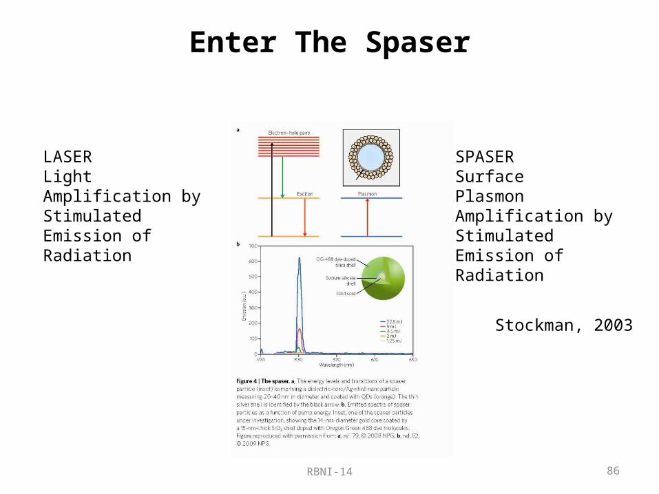
Enter The Spaser
LASERLightAmplification byStimulatedEmission ofRadiation
SPASERSurfacePlasmonAmplification byStimulatedEmission ofRadiation
Stockman, 2003

RBNI-14 87
Is Spaser Unique?
Very small amount of radiation is coming out for small SPASER
+++
+++
Energy is mostly contained in the matter, not field
d
Fraction of energy contained in free electron oscillations
2
1 dM
d gd
naf
Fraction of energy contained in bound electron oscillations in dielectric (polariton)
1gdD
d gd
f
dgd
Total fraction of energy in the electron vibrations:
2
1 1d gd
ed gd
na
f
For 40 nm GaAs Ag Spaser operating at 550nm 0.8ef
Ag
barrier
Intrinsic GaAs
BarrierAlAs
BarrierAlAs
N-doped AlGaAs
P-doped AlGaAs10nm

RBNI-14 88
Is Spaser Unique?
Consider a small semiconductor laser with high reflectivity mirrors Very small amount of radiation is coming out of it
Energy is mostly contained in the matter, not field
Fraction of energy contained in free electron oscillations 0Mf Fraction of energy contained in
bound electron oscillations in dielectric (polariton)
1gsS
s gs
f
2 2 ~ 22s s
gs s s s g
nn nn
Total fraction of energy in the electron vibrations: 1gse
s gs
f
For GaAs laser operating at 880 nm –strong dispersion!
0.60ef
+
+
+
+ +R>99%
In any laser operating in a dispersive material not a photon but a polariton is emitted and most of the energy is contained in electronic vibrations! The only difference is that in the SPASER it is free electrons. So what’ s so special? Big loss!

RBNI-14 89
Spaser and VCSEL
VCSEL
Ag
barrier
Intrinsic GaAs
BarrierAlAs
BarrierAlAs
N-doped AlGaAs
P-doped AlGaAs10nm
SPASER
Electric Field Energy10% 16%
Magnetic Field Energy30%3%
Free Electrons Energyin metal
45%
Bound Electrons Energyin semiconductor
60%
36%
FIELD
MATTER

RBNI-14 90
A very simple way to look at the spaser….
Rate equation for SP – bosonic particle
( 1)SPeff SP loss SP
dNg N N
dt
Metal loss
Semiconductor gain
g
g
loss metal rad
Spontaneous radiation
Spontaneous SPP emission –energy transfer from semiconductor to metal is at the rate of
/ 2eff lossg
Electrons flow
Holes flow
Current is
~ ~ 20lossI e A
Current density 2 6 2J ~ I / πr ~ 10 A / cm
This best case result does not depend on shape, size( as long as it is truly sub-wavelength, i.e. single mode) or on the gain material
The threshold is defined as 1SPN Equal probability of stimulated and spontaneous emission (linewidth is decreased by a factor of 2)
loss

RBNI-14 91
The current scales down with the volume only until the dimensions become sub-wavelength – after that – the same current has to go into progressively ever smaller volume –not a very good idea!
What happens?
1~tr eff tr P radI eV n F
We want to reduce the current by reducing the volume
Unfortunately…Purcell factor is inversely proportional to the volume
The current is proportional to the number of modes (confined and free space) into which the gain medium emits. The less is the volume the less is the number of modes. Until you have just one mode left. Then the volume stops being important.

RBNI-14 92
80 nm Single mode Au-InGaAs Spaser “emitting” at 1320 nm
P-contact N-contactAu
Active layer
10-7
10-6
10-5
10-4
1012
1013
1014
1015
Current (A)
SPP
emis
sion
rate
(1/s
) an
d Li
new
idth
(1/s
)
loss
effγ1 2 loss
tI
SPR
d
cb
a
-effective linewidth
“output”
0 100 200 3000
2
4
6
8
10
Current (A)
Carr
ier d
ensi
ty (1
018cm
-3)
tI
d
c
b
a
Input output characteristics shows no threshold
Linewidth narrowing indicates “spasing threshold” of 28 mA
Carrier density (gain) is clamped near threshold –sign of “spasing”
0 2 4 6 8 100
2
4
6
8
10
Carrier density (1018cm-3)
Num
ber o
f SPP
’s in
the
mod
e
,c thN
thre
shol
d
Near threshold half of SP’s are coherent and half have random phases – so it more like“SPED” rather than “SPASER”

RBNI-14 93
Lineshape evolution
0.7 0.8 0.9 1-6
-5
-4
-3
-2
-1
0
1
Energy (eV)
Mat
eria
l G
ain
(1014
s-1)
Mod
al g
ain
spec
tral
den
sity
(a.u
)(a)
Low pump
0.7 0.8 0.9 1-3
-2.5
-2
-1.5
-1
-0.5
0
0.5
1
Energy (eV)
Mat
eria
l G
ain
(1014
s-1)
Mod
al g
ain
spec
tral
den
sity
(a.u
)
(b)
Below threshold
0.7 0.8 0.9 1-2.5
-2
-1.5
-1
-0.5
0
0.5
1
1.5
Energy (eV)
Mat
eria
l G
ain
(1014
s-1)
Mod
al g
ain
spec
tral
den
sity
(a.u
)
(c)
At threshold
0.7 0.8 0.9 1-2
-1.5
-1
-0.5
0
0.5
1
1.5
Energy (eV)
Mat
eria
l Gai
n (1
014
s-1)
Mod
al ga
in sp
ectr
al d
ensit
y (
a.u)
(d)
Way above threshold

RBNI-14 94
The threshold current depends on
The threshold current does not depend on
Scattering Rate in Metal
•Shape of the Mode•Size of the mode as long as it is sub-wavelength in all 3 Dimensions•Confinement factor of the mode•Gain material! (as long as it works in a “normal laser”)•Temperature (weakly)•Wavelength (red, orange, IR, polka-dot) as long it is less than ~20mm•Longitude, Latitude, Altitude•Attitude of the scientist•Amount of money spent
thr eff spI = eγ n ~ 20μA

RBNI-14 95
Do we need a nanolaser?
• True sub-diffraction structure always require metal and thus inherently very lossy
• Therefore, threshold of the sub-diffraction laser will always be very high (20 mA in a tiny volume)
• There will be only a few photons (plasmons) in a mode – no coherence (linewidth of THz)
• But the device will be very fast (THz)
What if we just use spontaneous emission –SPED (Surface Plasmon Emitting Diode)?

RBNI-14 96
Characteristics of SPED
• Small volume –high density of integration• Low power consumption • Easier to cool• High speed due to Purcell Effect

RBNI-14 97
VCSEL, SPASER and SPED
Pump Current density (A/cm2)
Intr
aca
vity
Po
we
r (W
)L
inew
idth
(Hz)
102 103 104 105 106 107 10810-810-710-610-510-410-310-2
102 103 104 105 106 107 108106
108
1010
1012
1014
102 103 104 105 106 107 108108
109
1010
1011
1012
1013
Ma
xim
um
freq
ue
ncy
(H
z)
(a)
(b)
(c)
Pump Current density (A/cm2)
Pump Current density (A/cm2)
LED
VCSEL
SPED
SPASER
LEDVCSEL
SPED SPASER
LED
VCSEL
SPED
SPASER

RBNI-14 98
Conclusions:•Loss affects and limits everything that is purportedly good about plasmonics and metamaterials Reducing loss would change the paradigm.•To get sub-wavelength concentration of light in all three dimensions one does need material with e<0 (usually a metal)•In optical and near IR region it always leads to losses commensurate with rate of decay in metal -1/10 fs, but far IR and THz the situation is less dire –perhaps mid-IR I swhere the action should be•Primarily because of loss only very weak optical processes can be enhanced by plasmonic means (SERS) – any optical device that requires high efficiency cannot be improved by plasmonic means. Hence sensing is the most promising niche.•Loss in metals in optical range is fundamentally different from loss (resistance) at low frequencies.•Loss and negative dielectric constant can be decoupled (in the future)•Using phonon polaritons and other resonant schemes reduces loss but has drawbacks of its own•Compensating loss with gain is tricky and probably unrealistic•Incoherent sub-wavelength sources are just as good as lsub-waveelngth lasers and might have a future.
RBNI-14 99
Additional readingJ. B. Khurgin, G. Sun “In search of elusive lossless metal, Appl. Phys. Lett, 96, 181102 (2010) J. B. Khurgin, G. Sun, Enhancement of optical properties of nanoscaled objects by metal nanoparticles”, J. Opt. Soc. B, 26, 83 (2009) J. B. Khurgin, G. Sun, Impact of high-order surface plasmon modes of metal nanoparticles on enhancement of optical emission, Appl. Phys. Lett., 95, 171103 (2009)
J. B. Khurgin, G. Sun, “Enhancement of light absorption in quantum well by surface plasmon polariton”, Appl. Phys. Lett, 94, 191106 (2009) J. B. Khurgin, G. Sun, R. A. Soref, “Plasmonic enhancement of photoluminescence by metal nanoparticles”, Appl. Phys. Lett. 94, 101103 (2009); J. B. Khurgin, G. Sun, R. A. Soref, “Practical limits of absorption enhancement near metal nanoparticles”, Appl. Phys. Lett. 94, 071103 (2009) G. Sun, J.B. Khurgin, R. A. Soref, “Plasmonic light-emission enhancement with isolated metal nanoparticles and their coupled arrays “, J. Opt. Soc. Am. B 25, 1748 (2008) J.B. Khurgin, G. Sun, R. A. Soref “Electroluminescence efficiency enhancement using metal nanoparticles”, Appl. Phys. Lett., 93 021120 (2008) Khurgin JB, Sun G, Soref RA ”Enhancement of luminescence efficiency using surface plasmon polaritons: figures of merit” J. Opt. Soc. Am. B 24: 1968-1980 (2007) Khurgin JB ”Surface plasmon-assisted laser cooling of solids”, Phys. Rev. Lett 98, Art. No. 177401 (2007) Sun G, Khurgin JB, Soref RA ”Practicable enhancement of spontaneous emission using surface plasmons” Appl. Phys. Lett., 90 Art. No. 111107 (2007)

RBNI-14 100
J. B. Khurgin, A. Boltasseva, “Reflecting upon the losses in plasmonics and metamaterials”, MRS Bulletin , 37, 768-779 (2012)J. B. Khurgin , G. Sun, “Practicality of compensating the loss in the plasmonic waveguides using semiconductor gain medium”, Appl. Phys. Lett, 100, 011105 (2012)
J.B. Khurgin and G. Sun: “How small can “ Nano ” be in a “ Nanolaser ”?”, Nanophotonics, 1, 3-8 (2012) J. B. Khurgin, G. Sun, “Injection pumped single mode surface plasmon generators: threshold, linewidth, and coherence”, Optics Express 20 15309-15325 (2012) G. Sun, J. B. Khurgin, “Origin of giant difference between fluorescence, resonance, and nonresonance Raman scattering enhancement by surface plasmons”, Phys. Rev. A 85, 063410 (2012 JG. Sun, J. B. Khurgin, and D. P. Tsai, “Comparative analysis of photoluminescence and Raman enhancement by metal nanoparticles”, Opt. Letters, 37, 1583-1585 (2012) G. Sun, J. B. Khurgin, A. Bratkovsky “Coupled-mode theory of field enhancement in complex metal nanostructures “, Phys. Rev, B 84, 045415 (2011)J. B. Khurgin, G. Sun, Scaling of losses with size and wavelength in Nanoplasmonics” Appl. Phys. Lett, 99, 211106 (2011) B. Zhang, J. B. Khurgin, “Eigen mode approach to the sub-wavelength imaging with surface plasmon polaritons” Appl. Phys. Lett, 98, 263102 (2011) G. Sun, J. B. Khurgin, Optimization of the nanolens consisting of coupled metal nanoparticles: An analytical approach”, Appl. Phys. Lett, 98, 153115 (2011) G. Sun, J. B. Khurgin, “Plasmon Enhancement of Luminescence by Metal Nanoparticles : IEEE J. of Selected Topics In Quantum Electronics , 17 ,110 (2011) J. B. Khurgin, G. Sun , “Theory of optical emission enhancement by coupled metal nanoparticles: An analytical approach”, Appl. Phys. Lett 98, 113116 (2011) G. Sun, J. B. Khurgin, Comparative study of field enhancement between isolated and coupled metal nanoparticles: An analytical approach”, Appl. Phys. Lett. 97, 263110 (2010)

RBNI-14 101
Extra
RBNI-14 102
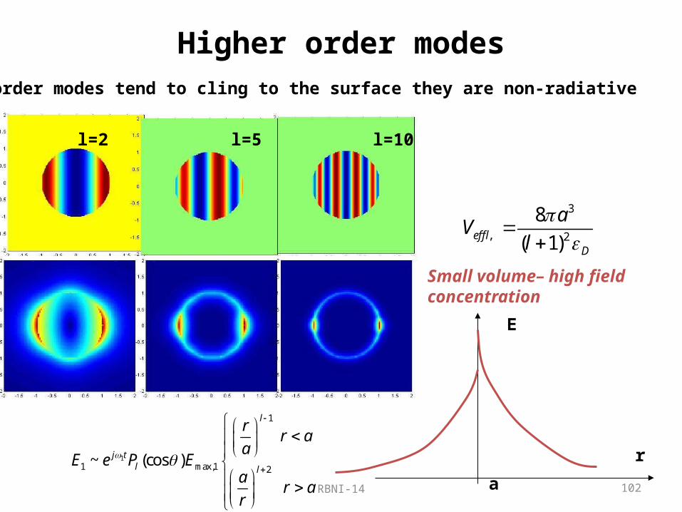
Higher order modes
l=2 l=5 l=10
High order modes tend to cling to the surface they are non-radiative
1
1
1 max,1 2
~ (cos )
l
j tl l
rr a
aE e P E
ar a
r
E
r
a
3
, 2
8
( 1)eff lD
aV
l
Small volume– high field concentration

RBNI-14 103
Impedance mismatchIn electronics in order to go from the high impedance circuit element (output stage of power amplifier-10K ) to the low impedance medium (coaxial cable -75, strip line) one usesImpedance transformer e.g. source follower
VDD
-VSS
IREF
vin
vout
Now we want “dense photons”to serve as a buffer between the emitting medium and the propagating photons
Can this buffer be lossless?

RBNI-14 104
Impedance mismatchIn electronics in order to go from the high impedance circuit element (output stage of power amplifier-10K ) to the low impedance medium (coaxial cable -75, strip line) one usesImpedance transformer e.g. source follower
VDD
-VSS
IREF
vin
vout
Now we want “dense photons”to serve as a buffer between the emitting medium and the propagating photons
Can this buffer be lossless?
RBNI-14 105
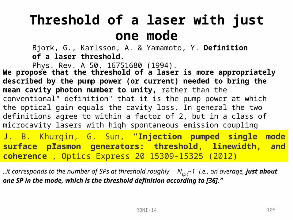
Threshold of a laser with just one mode
We propose that the threshold of a laser is more appropriately described by the pump power (or current) needed to bring the mean cavity photon number to unity, rather than the conventional“ definition" that it is the pump power at which the optical gain equals the cavity loss. In general the two definitions agree to within a factor of 2, but in a class of microcavity lasers with high spontaneous emission coupling efficiency and high absorption loss, the de6nitions may differ by several orders of magnitude.
Bjork, G., Karlsson, A. & Yamamoto, Y. Definition of a laser threshold.Phys. Rev. A 50, 16751680 (1994).
..it corresponds to the number of SPs at threshold roughly Nsp,t~1 i.e., on average, just about one SP in the mode, which is the threshold definition according to [36].”
J. B. Khurgin, G. Sun, “Injection pumped single mode surface plasmon generators: threshold, linewidth, and coherence”, Optics Express 20 15309-15325 (2012)
RBNI-14 106
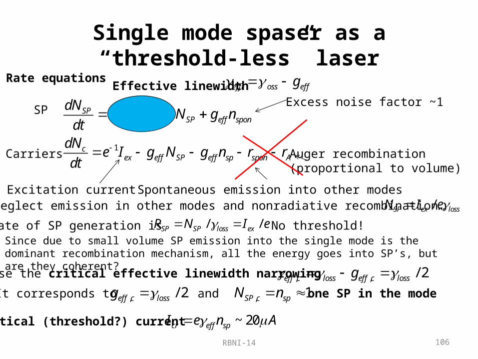
Single mode spaser as a “threshold-less” laser
1
SPeff loss SP eff spon
cex eff SP eff sp spon A
dNg N g n
dtdN
e I g N g n r rdt
Rate equations
SP
Carriers
Spontaneous emission into other modes
Auger recombination(proportional to volume)
Excess noise factor ~1
Excitation currentIf we neglect emission in other modes and nonradiative recombination… /SP ex lossN I e
Rate of SP generation is / /SP SP loss exR N I e No threshold! Since due to small volume SP emission into the single mode is the dominant recombination mechanism, all the energy goes into SP’s, but are they coherent?
Effective linewidth eff loss effg
We choose the critical effective linewidth narrowing , , / 2eff c loss eff c lossg It corresponds to , / 2eff c lossg and , 1SP c spN n one SP in the mode
Critical (threshold?) current ~ 20cr eff spI e n A