
Battery/Supercapacitor Combinations for Supplying Vehicle ... · Battery/Supercapacitor...
10
Battery/Supercapacitor Combinations for Supplying Vehicle Electrical and Electronic Loads Mohamed A M Mahmudi Staffordshire University, Stafford, UK Email: [email protected] Abdeladim A Gazwi The Higher Institute for Comprehensive Professions, Gamins, Libya Email: [email protected] Abstract—In automotive vehicle, battery plays a vital role in starting /cranking vehicle engines. High power density is a key requirement for this service. The performance of lead acid battery is limited due to many factors such as number of charge-discharge cycles and temperature. The introduction of a supercapacitor supplying the high power density is expected not only to increase life of the battery but also to reduce its size, capacity and weight. In this paper, a switching technique with current limiter capability has been investigated to control the switching sequence between the battery and the introduced supercapacitor. This technique reduces the power density required by the battery as well as providing greater number of starts with lesser cracking time intervals. The starting/cranking power density has also been reduced employing the developed control technique. An efficient and more robust starting/cranking technique has been developed. Index Terms—automotive application, batteries, experimental work, switching circuit, supercapacitors, battery audit I. INTRODUCTION Batteries and Supercapacitors are members of storage devices that play a vital role in wide verities of industrial applications. These applications used in low and high power applications starting from mobile phones and laptops to UPS and FACTS devices. These storage devices can be combined to form advanced power sources. Although the two devices belong to the same family they have different performance characteristics. In battery technology, the battery can provide high energy density but limited cycle life and poor power density, whereas supercapacitor has high capacitance and provides high power density with virtual unlimited cycle life but low energy density. If these two devices are combined together they would form advanced power sources based on energy storage principles. One of the Manuscript received October 3, 2013; revised February 25, 2014. batteries applications which are wildly used is the power source of automotive vehicles. Where the battery must provide high discharge current (cranking current), which affects the battery life. A direct combination (parallel) of the lead acid battery and supercapacitor does not prevent or limit the high discharge current drawn from the battery but shared between the battery and supercapacitor, therefore, a switching converter may be used to provide switching mode between the supercapacitor/battery combinations so that the battery would provide a limited charging current to supercapacitor and as consequence, the supercapacitor would supply the cranking current. Eventually, this combination with switching converter may lead in reduction in battery size, capacity and prolongs its life cycle. II. BATTERY TECHNOLOGY A battery is a member of energy storage devices family which consists of a single or multi- cells. The cell (Fig. 1 and Fig. 2) is the unit where chemical reaction is taking place inside a battery, resulting in energy conversion from chemical to electrical energy. Every cell has three main parts: a positive electrode terminal (Anode), a negative electrode terminal (Cathode), and liquid or solid that separates electrodes from each other (electrolyte). When an external circuit (load) is connected to the battery, an electrical current will flow through the circuit due to chemical reaction causing positive charge (Ions) to flow in one direction and negative charge (Electrons) flow in the other direction through the external circuit. The movement of electrically charged particles causes an electrical current to flow through the cell and into the external circuit that is connected to the cell terminal. They are categorized as primary batteries which are non-rechargeable and secondary batteries which are chargeable. Fig. 1 shows a simple single electrochemical cell. The chemical reaction is basically happen in the cell, which is the working unit that characterizes the battery. 153 International Journal of Electronics and Electrical Engineering Vol. 2, No. 2, June, 2014 ©2014 Engineering and Technology Publishing doi: 10.12720/ijeee.2.2.153-162
Transcript of Battery/Supercapacitor Combinations for Supplying Vehicle ... · Battery/Supercapacitor...
Battery/Supercapacitor Combinations for
Supplying Vehicle Electrical and Electronic
Loads
Mohamed A M Mahmudi Staffordshire University, Stafford, UK
Email: [email protected]
Abdeladim A Gazwi The Higher Institute for Comprehensive Professions, Gamins, Libya
Email: [email protected]
Abstract—In automotive vehicle, battery plays a vital role in
starting /cranking vehicle engines. High power density is a
key requirement for this service. The performance of lead
acid battery is limited due to many factors such as number
of charge-discharge cycles and temperature. The
introduction of a supercapacitor supplying the high power
density is expected not only to increase life of the battery
but also to reduce its size, capacity and weight. In this paper,
a switching technique with current limiter capability has
been investigated to control the switching sequence between
the battery and the introduced supercapacitor. This
technique reduces the power density required by the battery
as well as providing greater number of starts with lesser
cracking time intervals. The starting/cranking power
density has also been reduced employing the developed
control technique. An efficient and more robust
starting/cranking technique has been developed. Index Terms—automotive application, batteries,
experimental work, switching circuit, supercapacitors,
battery audit
I. INTRODUCTION
Batteries and Supercapacitors are members of storage
devices that play a vital role in wide verities of industrial
applications. These applications used in low and high
power applications starting from mobile phones and
laptops to UPS and FACTS devices. These storage
devices can be combined to form advanced power
sources.
Although the two devices belong to the same family
they have different performance characteristics. In
battery technology, the battery can provide high energy
density but limited cycle life and poor power density,
whereas supercapacitor has high capacitance and
provides high power density with virtual unlimited cycle
life but low energy density. If these two devices are
combined together they would form advanced power
sources based on energy storage principles. One of the
Manuscript received October 3, 2013; revised February 25, 2014.
batteries applications which are wildly used is the power
source of automotive vehicles. Where the battery must
provide high discharge current (cranking current), which
affects the battery life. A direct combination (parallel) of
the lead acid battery and supercapacitor does not prevent
or limit the high discharge current drawn from the battery
but shared between the battery and supercapacitor,
therefore, a switching converter may be used to provide
switching mode between the supercapacitor/battery
combinations so that the battery would provide a limited
charging current to supercapacitor and as consequence,
the supercapacitor would supply the cranking current.
Eventually, this combination with switching converter
may lead in reduction in battery size, capacity and
prolongs its life cycle.
II. BATTERY TECHNOLOGY
A battery is a member of energy storage devices
family which consists of a single or multi- cells. The cell
(Fig. 1 and Fig. 2) is the unit where chemical reaction is
taking place inside a battery, resulting in energy
conversion from chemical to electrical energy. Every cell
has three main parts: a positive electrode terminal
(Anode), a negative electrode terminal (Cathode), and
liquid or solid that separates electrodes from each other
(electrolyte). When an external circuit (load) is connected
to the battery, an electrical current will flow through the
circuit due to chemical reaction causing positive charge
(Ions) to flow in one direction and negative charge
(Electrons) flow in the other direction through the
external circuit. The movement of electrically charged
particles causes an electrical current to flow through the
cell and into the external circuit that is connected to the
cell terminal. They are categorized as primary batteries
which are non-rechargeable and secondary batteries
which are chargeable.
Fig. 1 shows a simple single electrochemical cell. The
chemical reaction is basically happen in the cell, which is
the working unit that characterizes the battery.
153
International Journal of Electronics and Electrical Engineering Vol. 2, No. 2, June, 2014
©2014 Engineering and Technology Publishingdoi: 10.12720/ijeee.2.2.153-162
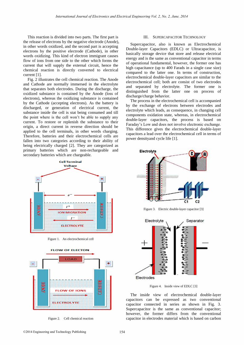
This reaction is divided into two parts. The first part is
the release of electrons by the negative electrode (Anode),
in other words oxidized, and the second part is accepting
electrons by the positive electrode (Cathode), in other
words oxidizing. This kind of electron immigrant causes
flow of ions from one side to the other which forms the
current that will supply the external circuit, hence the
chemical reaction is directly converted to electrical
current [1].
Fig. 2 illustrates the cell chemical reaction. The Anode
and Cathode are normally immersed in the electrolyte
that separates both electrodes. During the discharge, the
oxidized substance is contained by the Anode (loss of
electrons), whereas the oxidizing substance is contained
by the Cathode (accepting electrons). As the battery is
discharged, or generation of electrical current, the
substance inside the cell is stat being consumed and till
the point where is the cell won’t be able to supply any
current. To restore or replenish the substance to their
origin, a direct current in reverse direction should be
applied to the cell terminals, in other words charging.
Therefore, batteries and their electrochemical cells are
fallen into two categories according to their ability of
being electrically charged [2]. They are categorized as
primary batteries which are non-rechargeable and
secondary batteries which are chargeable.
Figure 1. An electrochemical cell
Figure 2. Cell chemical reaction
III. SUPERCAPACITOR TECHNOLOGY
Supercapacitor, also is known as Electrochemical
Double-layer Capacitors (EDLC) or Ultracapacitor, is
basically storage device that store and release electrical
energy and is the same as conventional capacitor in terms
of operational fundamental, however, the former one has
high capacitance (up to 400 Farads in a single case size)
compared to the latter one. In terms of construction,
electrochemical double-layer capacitors are similar to the
electrochemical cell; both are consist of two electrodes
and separated by electrolyte. The former one is
distinguished from the latter one on process of
discharge/charge behavior.
The process in the electrochemical cell is accompanied
by the exchange of electrons between electrodes and
electrolyte which leads, as consequence, in changing cell
components oxidation state, whereas, in electrochemical
double-layer capacitors, the process is based on
Faraday’s Low and does not involve electronic exchange.
This difference gives the electrochemical double-layer
capacitors a lead over the electrochemical cell in terms of
power densityand cycle life [1].
Figure 3. Electric double-layer capacitor [3]
Figure 4. Inside view of EDLC [3]
The inside view of electrochemical double-layer
capacitors can be expressed as two conventional
capacitor connected in series as shown in Fig. 3.
Supercapacitor is the same as conventional capacitor;
however, the former differs from the conventional
capacitor in electrodes material which is based on carbon
154
International Journal of Electronics and Electrical Engineering Vol. 2, No. 2, June, 2014
©2014 Engineering and Technology Publishing
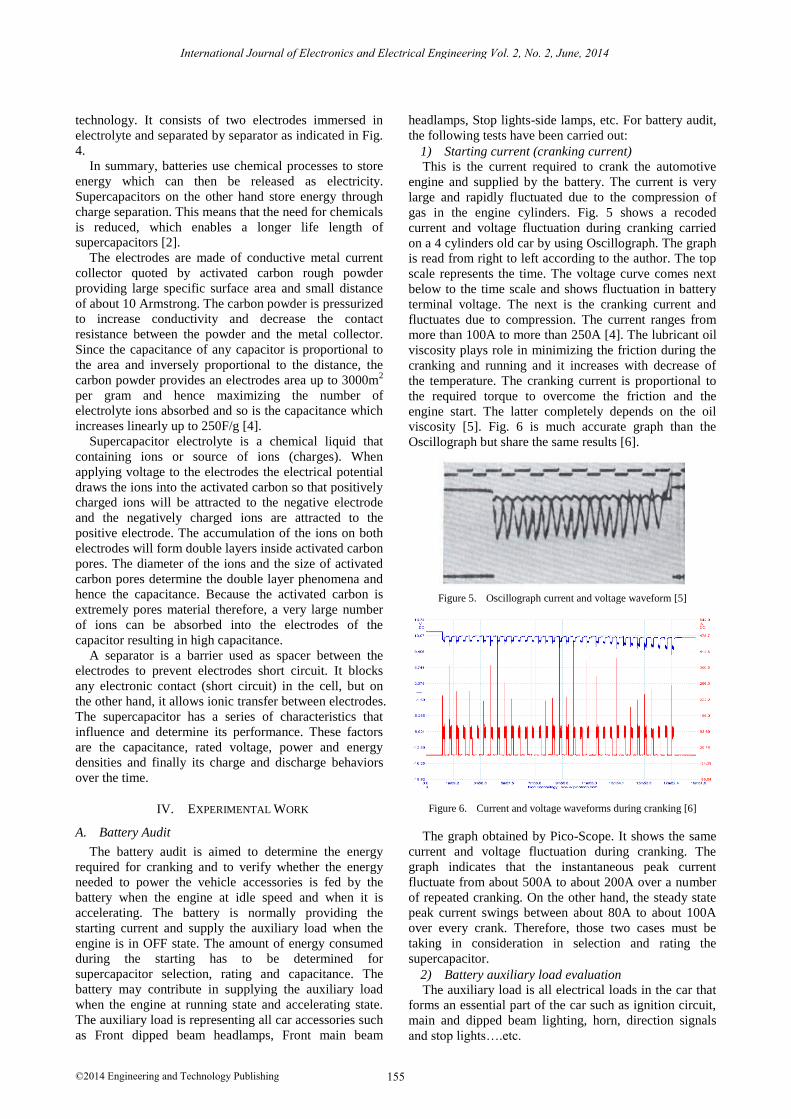
technology. It consists of two electrodes immersed in
electrolyte and separated by separator as indicated in Fig.
4.
In summary, batteries use chemical processes to store
energy which can then be released as electricity.
Supercapacitors on the other hand store energy through
charge separation. This means that the need for chemicals
is reduced, which enables a longer life length of
supercapacitors [2].
The electrodes are made of conductive metal current
collector quoted by activated carbon rough powder
providing large specific surface area and small distance
of about 10 Armstrong. The carbon powder is pressurized
to increase conductivity and decrease the contact
resistance between the powder and the metal collector.
Since the capacitance of any capacitor is proportional to
the area and inversely proportional to the distance, the
carbon powder provides an electrodes area up to 3000m2
per gram and hence maximizing the number of
electrolyte ions absorbed and so is the capacitance which
increases linearly up to 250F/g [4].
Supercapacitor electrolyte is a chemical liquid that
containing ions or source of ions (charges). When
applying voltage to the electrodes the electrical potential
draws the ions into the activated carbon so that positively
charged ions will be attracted to the negative electrode
and the negatively charged ions are attracted to the
positive electrode. The accumulation of the ions on both
electrodes will form double layers inside activated carbon
pores. The diameter of the ions and the size of activated
carbon pores determine the double layer phenomena and
hence the capacitance. Because the activated carbon is
extremely pores material therefore, a very large number
of ions can be absorbed into the electrodes of the
capacitor resulting in high capacitance.
A separator is a barrier used as spacer between the
electrodes to prevent electrodes short circuit. It blocks
any electronic contact (short circuit) in the cell, but on
the other hand, it allows ionic transfer between electrodes.
The supercapacitor has a series of characteristics that
influence and determine its performance. These factors
are the capacitance, rated voltage, power and energy
densities and finally its charge and discharge behaviors
over the time.
IV. EXPERIMENTAL WORK
A. Battery Audit
The battery audit is aimed to determine the energy
required for cranking and to verify whether the energy
needed to power the vehicle accessories is fed by the
battery when the engine at idle speed and when it is
accelerating. The battery is normally providing the
starting current and supply the auxiliary load when the
engine is in OFF state. The amount of energy consumed
during the starting has to be determined for
supercapacitor selection, rating and capacitance. The
battery may contribute in supplying the auxiliary load
when the engine at running state and accelerating state.
The auxiliary load is representing all car accessories such
as Front dipped beam headlamps, Front main beam
headlamps, Stop lights-side lamps, etc. For battery audit,
the following tests have been carried out:
1) Starting current (cranking current)
This is the current required to crank the automotive
engine and supplied by the battery. The current is very
large and rapidly fluctuated due to the compression of
gas in the engine cylinders. Fig. 5 shows a recoded
current and voltage fluctuation during cranking carried
on a 4 cylinders old car by using Oscillograph. The graph
is read from right to left according to the author. The top
scale represents the time. The voltage curve comes next
below to the time scale and shows fluctuation in battery
terminal voltage. The next is the cranking current and
fluctuates due to compression. The current ranges from
more than 100A to more than 250A [4]. The lubricant oil
viscosity plays role in minimizing the friction during the
cranking and running and it increases with decrease of
the temperature. The cranking current is proportional to
the required torque to overcome the friction and the
engine start. The latter completely depends on the oil
viscosity [5]. Fig. 6 is much accurate graph than the
Oscillograph but share the same results [6].
Figure 5. Oscillograph current and voltage waveform [5]
Figure 6. Current and voltage waveforms during cranking [6]
The graph obtained by Pico-Scope. It shows the same
current and voltage fluctuation during cranking. The
graph indicates that the instantaneous peak current
fluctuate from about 500A to about 200A over a number
of repeated cranking. On the other hand, the steady state
peak current swings between about 80A to about 100A
over every crank. Therefore, those two cases must be
taking in consideration in selection and rating the
supercapacitor.
2) Battery auxiliary load evaluation
The auxiliary load is all electrical loads in the car that
forms an essential part of the car such as ignition circuit,
main and dipped beam lighting, horn, direction signals
and stop lights….etc.
155
International Journal of Electronics and Electrical Engineering Vol. 2, No. 2, June, 2014
©2014 Engineering and Technology Publishing
It is obvious that every vehicle is equipped with an
alternator, which normally big enough to supply all
auxiliary loads plus charging the battery. However, the
power generated by the alternator is governed by the
engine revolutions, which on the other hand is governed
by the acceleration of the engine. As the engine
accelerates the alternator cycles increase and hence more
power would be generated. However, the situation may
different when the vehicle at stall or running at idle speed
(not accelerating). The following tests are run to verify
how the auxiliary loads are supplied during engine OFF,
engine ON (idle speed) and engine accelerating.
3) OFF engine test
The test is to determine the current supplied by the
battery when the engine is in off state. The car accessory
loads were switched on step by step starting from the fuel
pump and ending to the hazard indicator signals. Then
the same sequence repeated in switching off the car
accessory loads, hence the graph indicated in Fig. 7 was
obtained. The maximum peak current is 52.5Amps (Red
curve) and the battery terminal voltage (Goldenrod curve)
dropped from 12.51V to 11.48V. The battery terminal
voltage started to decrease when the load current at
7.74Amps and as the load switched on one by one the
battery terminal voltage continues to drop till the point
where the load current at its maximum peak.
Figure 7. Car accessory current and batter voltage graphs (OFF engine)
The fluctuation in the load current at the peak is due to
the changeable load such as fan, hazard signals and
screen wiper. As the load current switched off one by one,
the battery terminal voltage start to recover.
4) Engine running test (idle speed)
As the engine started on and run at idle speed the
alternator starts to provide current to supply car accessory
loads as well as the charging current, however, the
alternator generates power proportional to the engine
revolution. However when car accessory loads gradually
switched on. The charging current starts to decline
towards negative region. When the load reaches its
maximum current, the battery current changes its state to
negative, which means, the battery is now contributing in
supplying load and hence changed its state from being
receiving charging current to partially supplying the load
current.
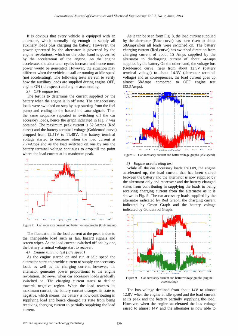
As it can be seen from Fig. 8, the load current supplied
by the alternator (Blue curve) has been risen to about
58Ampswhen all loads were switched on. The battery
charging current (Red curve) has switched direction from
charging current of about 15 Amps supplied by the
alternator to discharging current of about -4Amps
supplied by the battery.On the other hand, the voltage bus
(Goldenrod curve) rises from about 12.5V (battery
terminal voltage) to about 14.3V (alternator terminal
voltage) and as consequences, the load current goes up
almost 58Amps compared to OFF engine test
(52.5Amps).
Figure 8. Car accessory current and batter voltage graphs (idle speed)
5) Engine accelerating test
While all the car accessory loads are ON, the engine
accelerated up, the load current that has been shared
between the battery and the alternator is now supplied by
the alternator only and moreover and the battery changed
states from contributing in supplying the loads to being
receiving charging current from the alternator as it is
shown in Fig. 9. The car accessory loads supplied by the
alternator indicated by Red Graph, the charging current
indicated by Green Graph and the battery voltage
indicated by Goldenrod Graph.
Figure 9. Car accessory current and batter voltage graphs (engine accelerating)
The bus voltage declined from about 14V to almost
12.8V when the engine at idle speed and the load current
at its peak and the battery partially supplying the load.
However, when the engine accelerated the bus voltage
raised to almost 14V and the alternator is now able to
156
International Journal of Electronics and Electrical Engineering Vol. 2, No. 2, June, 2014
©2014 Engineering and Technology Publishing
supply the load current along to the battery charging
current.
6) Evaluation of battery audit
The tests carried above indicate that the battery does
contribute in supplying the auxiliary (5A maximum) load
under one condition that the auxiliary load is at its peak
or is switched on towards its peak during the engine at
idle speed. Because the engine was at idle speed, which
on the other hand, drive the alternator which its out
power depends on the engine RPM (Revaluation Per
Minute), hence the battery has to compensate the lack of
power demanded by the load. As the engine accelerates
the RPM increases and so the alternator output power
enable the alternator to supply the load demand plus
battery charging current.
7) Cracking energy consumption
The energy needed for cranking and starting the engine
was calculated from six starting times where the voltage
and the current were recorded and exported to Excel
software. The energy required per each start is calculated
by applying Simpson's rule as following:
∫ ( )
(
) (1)
where, (E) the energy delivered by the battery and P is
the product of the cranking current and battery terminal
voltage. (t) is the starting time in seconds and ( ) is the
time increments. (PO to Pn) is the power calculated per
time increments.
The calculated energy values are shown for each test
in Table I. From Table I, the energy required for every
start ranges from 705.93Ws to 762.82Ws so 800 Ws can
be considered as the energy required for every start [6].
TABLE I. THE CALCULATED ENERGY OF FIVE STARTING PERIODS [6]
Number of Tests Starting Period (s) Energy (Ws)
Test 1 0.809045 720.79
Test 2 0.766303 705.93
Test 3 0.796833 762.82
Test 4 0.744932 721.74
Test 5 0.793781 762.59
B. Implementation of Supercapacitor
In order to select the appropriate supercapacitor
modules, the Supercapacitors specifications and rating
requirements have been calculatedaccording to the
recorded data indicated in Table I, 800 Ws was
considered to be the energy required for every single start.
To provide three starts, the energy required is 2400Ws so
3000Ws was selected as safety margin, and for battery
terminal voltage of 12V, two supercapacitor modules
(BMOD0058 E016 B02) in parallel were selected,
forming 104 F, avoiding any damage that may happen
during supply the energy required by the starter motor [6].
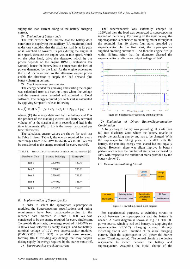
1) Supercapacitor cranking current
The supercapacitor was externally charged to
12.5Vand then the load was connected to supercapacitor
instead of the battery. By turning on the ignition key, the
supercapacitor is connected to cranking motor throughout
the solenoid. Fig. 10 shows four starts provided by
supercapacitor. In the first start, the supercapacitor
supplied cranking current of 132A then the engine fire up
within 516ms. After that the alternator charged the
supercapacitor to alternator output voltage of 14V.
Figure 10. Supercapacitor supplying cranking current
2) Evaluation of Direct Battery/Supercapacitor
Combination
A fully charged battery was providing 34 starts then
fall into discharge zone where the battery unable to
supply the cranking energy and has to be charged. With
the supercapacitor taking place in parallel with the
battery, the cranking energy was shared but not equally
shared. However, there was slight improve in battery
performance where the number of starts has increased by
41% with respect to the number of starts provided by the
battery alone [6].
C. Developing Switching Circuit
Figure 11. Switching circuit block diagram
For experimental purposes, a switching circuit to
switch between the supercapacitor and the battery is
needed. A block diagram is shown in Fig. 11. The DC
power source, which is lead acid battery, is supplying the
supercapacitor (EDLC) charging current through
switching circuit with limitation of the initial charging
current. Then the supercapacitor will power the Starter
motor (Cranking motor). The control circuit is the device
responsible to switch between the battery and
supercapacitor. Assuming the initial charge of the
157
International Journal of Electronics and Electrical Engineering Vol. 2, No. 2, June, 2014
©2014 Engineering and Technology Publishing
supercapacitor is zero, the control circuit will sense
zerovoltage across supercapacitor terminal and send a
signal to the switching device to switch on and start
charging the supercapacitor.On the other hand, it sends a
signal to prohibit any start during the supercapacitor
charge.
Once the supercapacitor is fully charged, the control
circuit will disconnect the supercapacitor fromthe battery
and connect the startermotor to the supercapacitor. After
a while, the supercapacitor terminal voltage will drop to
pre-determined low set point and disconnect the starter
motor and reconnect the battery till the supercapacitor
terminal voltage reaches the pre-determined high set
point.
D. Supercapacitor Initial Charging Current Limiting
Circuit
The initial charging current for zero charged and 94%
charged supercapacitor is very high. This current has to
be limited in some way. There are different methods in
limiting the initial current by using power semiconductor
devices such as power metal oxide-semiconductor field-
effect transistor (MOSFET), power bipolar junction
transistor (BJT) and power resistor.
E. Voltage Monitor Circuit
The supercapacitor terminal voltage gradually drops
when load is connected across its terminal as it gets
discharged. At certain point, the supercapacitor won’t be
able to drive the starter motor (cranking motor) and its
terminal voltage drops down to or below the starter motor
cut-off voltage. Due to this drop in voltage, the
supercapacitor needs to be monitored during the whole
period of testing. Therefore a simple voltage monitoring
circuit was developed as shown in Fig. 12.
Figure 12. Voltage monitoring circuit
1) Switching circuit/current limiter coupling and
testing
The voltage monitor circuit is combined with Initial
current limiter circuit to represent final testing circuit but
with variable power resistive load of 8.5Ω and 8.5A.
A12V 24 AH (VBATT) is used as well as external DC
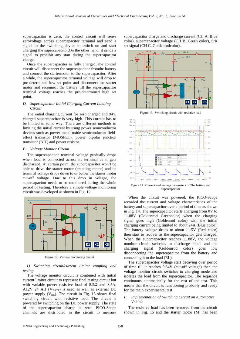
power supply (VDC). The circuit in Fig. 13 shows final
switching circuit with resistive load. The circuit is
powered by switching on the DC power supply. The state
of the supercapacitor charge is zero. PICO-Scope
channels are distributed in the circuit to measure
supercapacitor charge and discharge current (CH A, Blue
color), supercapacitor voltage (CH B, Green color), S/R
set signal (CH C, Goldenrodcolor).
Figure 13. Switching circuit with resistive load
Figure 14. Current and voltage parameters of The battery and supercapacitor
When the circuit was powered, the PICO-Scope
recorded the current and voltage characteristics of the
battery and supercapacitor over a period of time as shown
in Fig. 14. The supercapacitor starts charging from 0V to
11.88V (Goldenrod Greencolor) when the charging
signal goes high (Goldenrod color) with the initial
charging current being limited to about 24A (Blue color).
The battery voltage drops to about 11.5V (Red color)
then start to recover as the supercapacitor gets charged.
When the supercapacitor reaches 11.88V, the voltage
monitor circuit switches to discharge mode and the
charging signal (Goldenrod color) goes low
disconnecting the supercapacitor from the battery and
connecting it to the load (RL).
The supercapacitor voltage start decaying over period
of time till it reaches 9.34V (cut-off voltage) then the
voltage monitor circuit switches to charging mode and
isolates the load from the supercapacitor. The sequence
continuous automatically for the rest of the test. This
means that the circuit is functioning probably and ready
for the main experimental test.
F. Implementation of Switching Circuit on Automotive
Vehicle
The resistive load has been removed from the circuit
shown in Fig. 15 and the starter motor (M) has been
158
International Journal of Electronics and Electrical Engineering Vol. 2, No. 2, June, 2014
©2014 Engineering and Technology Publishing
connected instead. The engine was disabled from fire up
during the test for testing purposes as well as the car
accessory load. The positive lead of the starter motor (M)
is connected to the positive pole of the supercapacitor
throughout the solenoid switch (S). The ignition key is
also disabled and its function is now carried by the relays
(K2 and K3) which can start cranking automatically.
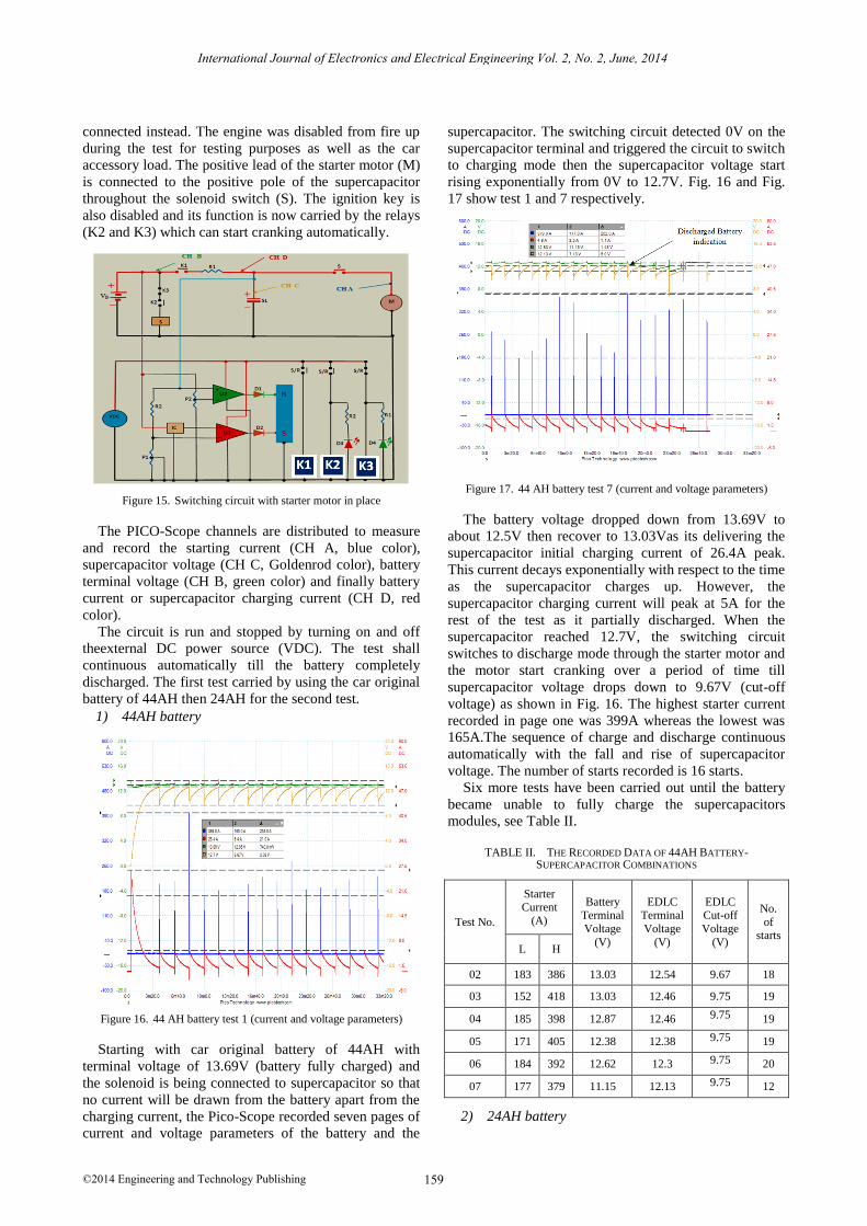
Figure 15. Switching circuit with starter motor in place
The PICO-Scope channels are distributed to measure
and record the starting current (CH A, blue color),
supercapacitor voltage (CH C, Goldenrod color), battery
terminal voltage (CH B, green color) and finally battery
current or supercapacitor charging current (CH D, red
color).
The circuit is run and stopped by turning on and off
theexternal DC power source (VDC). The test shall
continuous automatically till the battery completely
discharged. The first test carried by using the car original
battery of 44AH then 24AH for the second test.
1) 44AH battery
Figure 16. 44 AH battery test 1 (current and voltage parameters)
Starting with car original battery of 44AH with
terminal voltage of 13.69V (battery fully charged) and
the solenoid is being connected to supercapacitor so that
no current will be drawn from the battery apart from the
charging current, the Pico-Scope recorded seven pages of
current and voltage parameters of the battery and the
supercapacitor. The switching circuit detected 0V on the
supercapacitor terminal and triggered the circuit to switch
to charging mode then the supercapacitor voltage start
rising exponentially from 0V to 12.7V. Fig. 16 and Fig.
17 show test 1 and 7 respectively.
Figure 17. 44 AH battery test 7 (current and voltage parameters)
The battery voltage dropped down from 13.69V to
about 12.5V then recover to 13.03Vas its delivering the
supercapacitor initial charging current of 26.4A peak.
This current decays exponentially with respect to the time
as the supercapacitor charges up. However, the
supercapacitor charging current will peak at 5A for the
rest of the test as it partially discharged. When the
supercapacitor reached 12.7V, the switching circuit
switches to discharge mode through the starter motor and
the motor start cranking over a period of time till
supercapacitor voltage drops down to 9.67V (cut-off
voltage) as shown in Fig. 16. The highest starter current
recorded in page one was 399A whereas the lowest was
165A.The sequence of charge and discharge continuous
automatically with the fall and rise of supercapacitor
voltage. The number of starts recorded is 16 starts.
Six more tests have been carried out until the battery
became unable to fully charge the supercapacitors
modules, see Table II.
TABLE II. THE RECORDED DATA OF 44AH BATTERY-SUPERCAPACITOR COMBINATIONS
Test No.
Starter
Current
(A)
Battery
Terminal
Voltage
(V)
EDLC
Terminal
Voltage
(V)
EDLC
Cut-off
Voltage
(V)
No.
of starts
L H
02 183 386 13.03 12.54 9.67 18
03 152 418 13.03 12.46 9.75 19
04 185 398 12.87 12.46 9.75 19
05 171 405 12.38 12.38 9.75 19
06 184 392 12.62 12.3 9.75 20
07 177 379 11.15 12.13 9.75 12
2) 24AH battery
159
International Journal of Electronics and Electrical Engineering Vol. 2, No. 2, June, 2014
©2014 Engineering and Technology Publishing
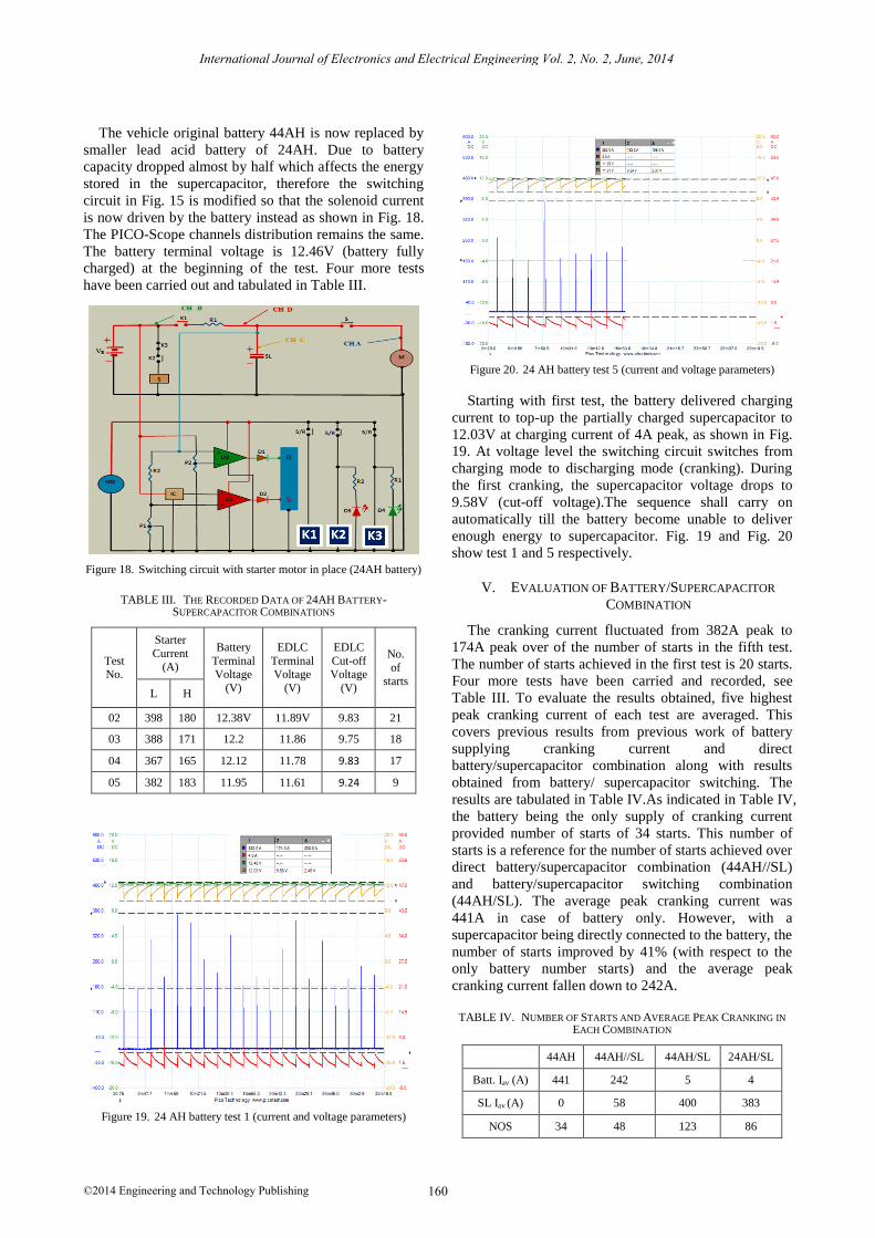
The vehicle original battery 44AH is now replaced by
smaller lead acid battery of 24AH. Due to battery
capacity dropped almost by half which affects the energy
stored in the supercapacitor, therefore the switching
circuit in Fig. 15 is modified so that the solenoid current
is now driven by the battery instead as shown in Fig. 18.
The PICO-Scope channels distribution remains the same.
The battery terminal voltage is 12.46V (battery fully
charged) at the beginning of the test. Four more tests
have been carried out and tabulated in Table III.
Figure 18. Switching circuit with starter motor in place (24AH battery)
TABLE III. THE RECORDED DATA OF 24AH BATTERY-SUPERCAPACITOR COMBINATIONS
Test No.
Starter
Current (A)
Battery
Terminal Voltage
(V)
EDLC
Terminal Voltage
(V)
EDLC
Cut-off Voltage
(V)
No.
of
starts L H
02 398 180 12.38V 11.89V 9.83 21
03 388 171 12.2 11.86 9.75 18
04 367 165 12.12 11.78 9.83 17
05 382 183 11.95 11.61 9.24 9
Figure 19. 24 AH battery test 1 (current and voltage parameters)
Figure 20. 24 AH battery test 5 (current and voltage parameters)
Starting with first test, the battery delivered charging
current to top-up the partially charged supercapacitor to
12.03V at charging current of 4A peak, as shown in Fig.
19. At voltage level the switching circuit switches from
charging mode to discharging mode (cranking). During
the first cranking, the supercapacitor voltage drops to
9.58V (cut-off voltage).The sequence shall carry on
automatically till the battery become unable to deliver
enough energy to supercapacitor. Fig. 19 and Fig. 20
show test 1 and 5 respectively.
V. EVALUATION OF BATTERY/SUPERCAPACITOR
COMBINATION
The cranking current fluctuated from 382A peak to
174A peak over of the number of starts in the fifth test.
The number of starts achieved in the first test is 20 starts.
Four more tests have been carried and recorded, see
Table III. To evaluate the results obtained, five highest
peak cranking current of each test are averaged. This
covers previous results from previous work of battery
supplying cranking current and direct
battery/supercapacitor combination along with results
obtained from battery/ supercapacitor switching. The
results are tabulated in Table IV.As indicated in Table IV,
the battery being the only supply of cranking current
provided number of starts of 34 starts. This number of
starts is a reference for the number of starts achieved over
direct battery/supercapacitor combination (44AH//SL)
and battery/supercapacitor switching combination
(44AH/SL). The average peak cranking current was
441A in case of battery only. However, with a
supercapacitor being directly connected to the battery, the
number of starts improved by 41% (with respect to the
only battery number starts) and the average peak
cranking current fallen down to 242A.
TABLE IV. NUMBER OF STARTS AND AVERAGE PEAK CRANKING IN
EACH COMBINATION
44AH 44AH//SL 44AH/SL 24AH/SL
Batt. Iav (A) 441 242 5 4
SL Iav (A) 0 58 400 383
NOS 34 48 123 86
160
International Journal of Electronics and Electrical Engineering Vol. 2, No. 2, June, 2014
©2014 Engineering and Technology Publishing
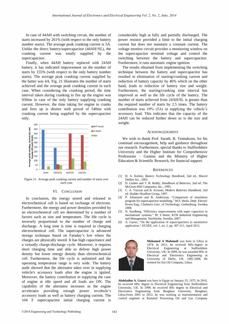
In case of 44AH with switching circuit, the number of
starts increased by 261% (with respect to the only battery
number starts). The average peak cranking current is 5A.
Unlike the direct battery/supercapacitor (44AH//SL), the
cranking current was totally supplied by the
supercapacitor.
Finally, when 44AH battery replaced with 24AH
battery, it has indicated improvement on the number of
starts by 155% (with respect to the only battery number
starts). The average peak cranking current supplied by
the batter was 4A. Fig. 21 illustrates the number of starts
achieved and the average peak cranking current in each
case. When considering the cranking period, the time
interval taken during cranking to fire up the engine was
930ms in case of the only battery supplying cranking
current. However, the time taking for engine to cranks
and fires up is shorter with period of 540ms with
cranking current being supplied by the supercapacitor
only.
Figure 21. Average peak cranking current and number of starts over each case
VI. CONCLUSION
In conclusion, the energy stored and released in
electrochemical cell is based on exchange of electrons.
Furthermore, the energy and power densities provided by
an electrochemical cell are determined by a number of
factors such as size and temperature. The life cycle is
inversely proportional to the number of charge and
discharge. A long time is time is required in charging
electrochemical cell. The supercapacitor is advanced
storage technique based on Faraday’s low where the
charges are physically stored. It has high capacitance and
a virtually charge-discharge cycle. Moreover, it requires
short charging time and able to deliver high power
density but lower energy density than electrochemical
cell. Furthermore, the life cycle is unlimited and the
operating temperature range is very wide. The battery
audit showed that the alternator takes over in supplying
vehicle's accessory loads after the engine is ignited.
Moreover, the battery contribution in supplying the case
of engine at idle speed and all loads are ON. The
capability of the alternator increases as the engine
accelerates providing enough power tovehicle’s
accessory loads as well as battery charging current. The
104 F supercapacitor initial charging current is
considerably high at fully and partially discharged. The
power resistor provided a limit to the initial charging
current but does not maintain a constant current. The
voltage monitor circuit provides a monitoring window on
the supercapacitor terminal voltage and control the
switching between the battery and supercapacitor.
Furthermore, it runs automatic engine ignition.
The results obtained from implementing the switching
technique between the battery and supercapacitor has
resulted in elimination of starting/cranking current and
reduction of battery capacity by 46% which on the other
hand, leads to reduction of battery size and weight.
Furthermore, the starting/cranking time interval has
improved as well as the life cycle of the battery. The
number of starts achieved from 24AH/SL is greater than
the required number of starts by 2.5 times. The battery
contribution was 10% (5A) in supplying the vehicle’s
accessory load. This indicates that the capacity of the
24AH can be reduced further down so is the size and
weight.
ACKNOWLEDGMENT
We wish to thank Prof. Sarath. B. Tennakoon, for his
continual encouragement, help and guidance throughout
our research. Furthermore, special thanks to Staffordshire
University and the Higher Institute for Comprehensive
Professions – Gamins and the Ministry of Higher
Education & Scientific Research, for financial support.
REFERENCES
[1] H. A. Kiehne, Battery Technology Handbook, 2nd ed., Marcel
Dekker Inc., 2003.
[2] D. Linden and T. B. Reddy, Handbook of Batteries, 2nd ed. The McGraw-Hill Companies, Inc., 1995.
[3] C. A. Vincent and B. Scrosati, Modern Batteries Handbook, 2nd
ed. Hodder Headline Group, 1997. [4] P. Johansson and B. Andersson, “Comparison of simulation
program for supercapacitor modelling,” M.S. thesis, Dept. Electric
Power Eng., Chalmers Univ. of Technology, Gothenburg, Sweden, 2008.
[5] N. Sundberg, “Efficiency improvements with super capacitors in
mechatronic systems,” M. S thesis, KTH Industrial Engineering and Management, Stockholm, Sweden, 2007.
[6] A. Gazwi, “On the application of supercapacitors to automotive
application,” IJCSEE, vol. 1, no. 2, pp. 307-311, April 2013.
Mohamed A Mahmudi was born in Libya in
1974. In 2011, he received MSc degree in Electrical Engineering at Staffordshire
University, UK. In 2009, he was awarded BSc in
Electrical and Electronics Engineering at University of Derby, UK. 1992-2008, He
worked for Eni Oil Company, Libya.
Abdeladim A. Gazwi was born in Egypt on January 25, 1975. In 2010, he received MSc degree in Electrical Engineering from Staffordshire
University, UK. In 1999, he received BSc degree in Electrical and
Electronics Engineering from Benghazi University, Benghazi, Libya.From 2001 to 2012, he was working as instrumentation and
control engineer at Raslanuf Processing Oil and Gas Company
161
International Journal of Electronics and Electrical Engineering Vol. 2, No. 2, June, 2014
©2014 Engineering and Technology Publishing

(RASCO), Libya. In May, 2012 he was a lecturer and the manager of the office of Technical and Scientific Affairs at The Higher Institute for
Comprehensive Professions- Gamins, Libya. And now, he is the
chairman of the institute. Mr. Gazwi is a membership ofISAET
Organization. In 2011 - 2013 papers have been published, Modelling of Supercapacitor Modules and Parameters Extraction (46th UPEC Conf.,
2011) in addition to that and Application of Supercapacitors to
Automotive Application (ISAET Conf., 2013).
162
International Journal of Electronics and Electrical Engineering Vol. 2, No. 2, June, 2014
©2014 Engineering and Technology Publishing