(Battery) Rider−Scrubber Operator Manualaz295482.vo.msecnd.net/globalassets/globalassets/all...
56
T 7 *331040* Rider-Scrubber Operator Manual 331040 Rev. 05 (09-2013) North America / International Hygenic Fully Cleanable Tanks R The Safe Scrubbing Alternative R (Battery) To view, print or download the latest manual, visit: www.tennantco.com/manuals
Transcript of (Battery) Rider−Scrubber Operator Manualaz295482.vo.msecnd.net/globalassets/globalassets/all...
T7
*331040*
Rider−ScrubberOperator Manual
331040Rev. 05 (09-2013)
North America / International
Hygenic Fully Cleanable Tanks�
The Safe Scrubbing Alternative�
(Battery)
To view, print or downloadthe latest manual, visit:
www.tennantco.com/manuals

INTRODUCTION
This manual is furnished with each new model. It provides necessary operation and maintenance instructions.
Read this manual completely and understand the machine before operating or servicing it.
This machine will provide excellent service. However, the best results will be obtained at minimum costs if:
� The machine is operated with reasonable care.
� The machine is maintained regularly - per the machine maintenance instructions provided.
� The machine is maintained with manufacturer supplied or equivalent parts.
PROTECT THE ENVIRONMENTPlease dispose of packagingmaterials, used components such asbatteries and fluids in anenvironmentally safe way according tolocal waste disposal regulations.
Always remember to recycle.
Model No. −
Serial No. −
Installation Date −
Please fill out at time of installation for future reference.
MACHINE DATA
INTENDED USE
The Speed Scrub Rider is an industrial/commercial rider machine designed to wet scrub both rough and smooth hardsurfaces (concrete, tile, stone, synthetic, etc). Typical applications include schools, hospitals / health care facilities,office buildings, and retail centers. Do not use this machine on soil, grass, artificial turf, or carpeted surfaces. Thismachine is intended for indoor use only. This machine is not intended for use on public roadways. Do not use thismachine other than described in this Operator Manual.
Tennant CompanyPO Box 1452Minneapolis, MN 55440Phone: (800) 553−8033 or (763) 513−2850www.tennantco.com
FaST−PAK is a US registered and unregistered trademark of Tennant Company.
Specifications and parts are subject to change without notice.
Copyright � 2004−2009, 2013 TENNANT Company, Printed in U.S.A.

CONTENTS
1T7 331040 (9−2013)
CONTENTS
PageSafety Precautions 2. . . . . . . . . . . . . . . . . . . . . . .Operation 5. . . . . . . . . . . . . . . . . . . . . . . . . . . . . . .
Machine Components 5. . . . . . . . . . . . . . . . . .Controls And Instruments 6. . . . . . . . . . . . . . .How The Machine Works 7. . . . . . . . . . . . . . .Conventional Scrubbing 7. . . . . . . . . . . . . . . .Foam Scrubbing System (FaST Model) 7. . .ec−H2O Scrubbing (ec−H2O Model) 8. . . . .Brush Information 8. . . . . . . . . . . . . . . . . . . . .Machine Setup 9. . . . . . . . . . . . . . . . . . . . . . . .Attaching Squeegee Assembly 9. . . . . . . . . .Installing Brushes/Pads 9. . . . . . . . . . . . . . . .Installing The FaST−PAK (FaST Model) 9. .Filling The Solution Tank 10. . . . . . . . . . . . . . . .Machine Operation 10. . . . . . . . . . . . . . . . . . . .Pre−Operation Checklist 10. . . . . . . . . . . . . . . .Before Operating 10. . . . . . . . . . . . . . . . . . . . . .Setting Scrub Modes 11. . . . . . . . . . . . . . . . . . .Setting FaST Button 11. . . . . . . . . . . . . . . . . . .Setting ec−H2O Button 11. . . . . . . . . . . . . . . . .Setting Brush Pressure 11. . . . . . . . . . . . . . . . .Setting Solution Flow
(Conventional Scrubbing Only) 11. . . . . . .Economy Setting 12. . . . . . . . . . . . . . . . . . . . . .Scrubbing 12. . . . . . . . . . . . . . . . . . . . . . . . . . . .Double Scrubbing 14. . . . . . . . . . . . . . . . . . . . .Water Pickup Mode (No Scrubbing) 15. . . . . .While Operating The Machine 15. . . . . . . . . . .Emergency Stop Button 16. . . . . . . . . . . . . . . .Hour Meter 16. . . . . . . . . . . . . . . . . . . . . . . . . .ec−H2O System Indicator Light 16. . . . . . . . . .Solution Tank Empty Indicator 17. . . . . . . . . . .Recovery Tank Full Indicator 17. . . . . . . . . . . .Battery Discharge Indicator 17. . . . . . . . . . . . .Fault Indicator 18. . . . . . . . . . . . . . . . . . . . . . . . .Circuit Breakers 19. . . . . . . . . . . . . . . . . . . . . . .Fuses 19. . . . . . . . . . . . . . . . . . . . . . . . . . . . . . .Hazard Light Switch (Option) 19. . . . . . . . . . . .Draining And Cleaning The Tanks 20. . . . . . . .Propel System Troubleshooting 22. . . . . . . . . .Machine Troubleshooting 23. . . . . . . . . . . . . . .
Maintenance 25. . . . . . . . . . . . . . . . . . . . . . . . . . . . .Maintenance Chart 26. . . . . . . . . . . . . . . . . . . .Batteries 27. . . . . . . . . . . . . . . . . . . . . . . . . . . . .Checking The Electrolyte Level
(Wet / Lead Acid Batteries Only) 27. . . . . .Checking Connections / Cleaning 27. . . . . . . .Gel Batteries 27. . . . . . . . . . . . . . . . . . . . . . . . . .Charging The Batteries With
Off−Board Charger 28. . . . . . . . . . . . . . . . . .Checking On−Board Battery
Charger Settings 29. . . . . . . . . . . . . . . . . . .Charging The Batteries With The
On−Board Charger 29. . . . . . . . . . . . . . . . . .On−Board Battery Charger Error Codes 30. .
PageElectric Motors 31. . . . . . . . . . . . . . . . . . . . . . . .Belts (Cylindrical Models) 31. . . . . . . . . . . . . . .Scrub Brushes And Pads 32. . . . . . . . . . . . . . .Disk Brushes 32. . . . . . . . . . . . . . . . . . . . . . . . .Replacing Disk Brushes Or Pad Driver 32. . .Replacing Disk Pads 33. . . . . . . . . . . . . . . . . . .Cylindrical Brushes 34. . . . . . . . . . . . . . . . . . . .Replacing Or Rotating Cylindrical Brushes 34Checking Cylindrical Brush Pattern 35. . . . . .Adjusting Cylindrical Brush Taper 36. . . . . . . .Adjusting Cylindrical Brush Width 37. . . . . . . .FaST System Maintenance (FaST Model) 38FaST Supply Hose Connector 38. . . . . . . . . . .ec−H2O System (ec−H2O Model) 39. . . . . . .ec−H2O Module Flush Procedure 39. . . . . . . .Squeegee Blades 39. . . . . . . . . . . . . . . . . . . . . .Replacing (Or Rotating) The Rear
Squeegee Blades 40. . . . . . . . . . . . . . . . . . .Replacing Side Squeegee Blades 41. . . . . . . .Adjusting The Squeegee Guide Roller 42. . . .Leveling The Rear Squeegee 42. . . . . . . . . . .Adjusting Rear Squeegee Blade
Deflection 43. . . . . . . . . . . . . . . . . . . . . . . . .Skirts And Seals 44. . . . . . . . . . . . . . . . . . . . . . .Disk Scrub Head Floor Skirt 44. . . . . . . . . . . . .Recovery Tank Seal 44. . . . . . . . . . . . . . . . . . .Solution Tank Seals 44. . . . . . . . . . . . . . . . . . . .Tires 44. . . . . . . . . . . . . . . . . . . . . . . . . . . . . . . . .Pushing, Towing, And Transporting
The Machine 45. . . . . . . . . . . . . . . . . . . . . . .Pushing Or Towing The Machine 45. . . . . . . .Transporting The Machine 45. . . . . . . . . . . . . .Machine Jacking 46. . . . . . . . . . . . . . . . . . . . . .Storage Information 46. . . . . . . . . . . . . . . . . . . .Freeze Protection 46. . . . . . . . . . . . . . . . . . . . .ec−H2O Model: 46. . . . . . . . . . . . . . . . . . . . . . .Flushing Antifreeze From
ec−H2O Module: 47. . . . . . . . . . . . . . . . . . .Specifications 48. . . . . . . . . . . . . . . . . . . . . . . . . .
General Machine Dimensions/Capacities 48.General Machine Performance 48. . . . . . . . . .Power Type 49. . . . . . . . . . . . . . . . . . . . . . . . . . .Tires 49. . . . . . . . . . . . . . . . . . . . . . . . . . . . . . . . .FaST System (Option) 49. . . . . . . . . . . . . . . . .ec−H2O System (Option) 49. . . . . . . . . . . . . . .Machine Dimensions 50. . . . . . . . . . . . . . . . . . .

SAFETY PRECAUTIONS
T7 331040 (9−2013)2
IMPORTANT SAFETY INSTRUCTIONS − SAVE THESE INSTRUCTIONS
The following symbols are used throughout thismanual as indicated in the descriptions:
WARNING: To warn of hazards orunsafe practices that could result insevere personal injury or death.
FOR SAFETY: To identify actions thatmust be followed for safe operation ofequipment.
The following information signals potentiallydangerous conditions to the operator. Know whenthese conditions can exist. Locate all safetydevices on the machine. Report machine damageor faulty operation immediately.
WARNING: Batteries emit hydrogen gas.Explosion or fire can result. Keepsparks and open flame away. Keepcovers open when charging.
WARNING: Flammable materials cancause an explosion or fire. Do not useflammable materials in tank(s).
WARNING: Flammable materials orreactive metals can cause an explosionor fire. Do not pick up.
FOR SAFETY:
1. Do not operate machine:− Unless trained and authorized.− Unless operator manual is read and
understood.− Under the influence of alcohol or
drugs− While using a cell phone or other
types of electronic devices− Unless mentally and physically
capable of following machineinstructions.
− With brake disabled.− If it is not in proper operating
condition.− In areas where flammable
vapors/liquids or combustible dustsare present.
− In areas that are too dark to safely seethe controls or operate the machineunless operating / headlights areturned on.
− In areas with possible falling objectsunless equipped with overhead guard.
2. Before starting machine:− Check machine for fluid leaks.− Make sure all safety devices are in
place and operate properly.− Check brakes and steering for proper
operation.− Adjust seat and fasten seat belt (if
equipped).
3. When using machine:− Use only as described in this manual.− Use brakes to stop machine.− Go slowly on inclines and slippery
surfaces.− Reduce speed when turning.− Keep all parts of body inside operator
station while machine is moving.− Use care when reversing machine.− Never allow children to play on or
around machine.− Do not carry passengers on machine.− Always follow safety and traffic rules.− Report machine damage or faulty
operation immediately.− Follow mixing, handling and disposal
instructions on chemical containers.− Follow site safety guidelines
concerning wet floors.

SAFETY PRECAUTIONS
3T7 331040 (9−2013)
4. Before leaving or servicing machine:− Stop on level surface.− Turn off machine and remove key.
5. When servicing machine:− All work must be done with sufficient
lighting and visibility.− Avoid moving parts. Do not wear loose
clothing, jewelry and secure long hair.− Block machine tires before jacking
machine up.− Jack machine up at designated
locations only. Support machine withjack stands.
− Use hoist or jack that will support theweight of the machine.
− Do not push or tow the machine oninclines with the brake disabled.
− Do not power spray or hose offmachine near electrical components.
− Disconnect battery connections beforeworking on machine.
− Avoid contact with battery acid.− Battery installation must be done by
trained personnel.− All repairs must be performed by a
trained service mechanic.− Do not modify the machine from its
original design.− Use Tennant supplied or approved
replacement parts.− Wear personal protective equipment
as needed and where recommended inthis manual.
For Safety: wear hearing protection.
For Safety: wear protective gloves.
For Safety: wear eye protection.
For Safety: wear protective dust mask.
6. When loading/unloading machineonto/off truck or trailer.− Drain tanks before loading machine.− Lower scrub head and squeegee
before tying down machine.− Turn off machine and remove key.− Use ramp, truck or trailer that will
support the weight of the machine andoperator.
− Use winch. Do not push the machineonto/off the truck or trailer unless theload height is 380 mm (15 in) or lessfrom the ground.
− Block machine tires.− Tie machine down to truck or trailer.

SAFETY PRECAUTIONS
T7 331040 (9−2013)4
The safety labels appear on the machine in thelocations indicated. If these or any label becomesdamaged or illegible, install a new label in itsplace.
Located on the seat panel
Located on the seat panel
Located on the seatpanel
Located under the solution fillport and next to foot pedals
Located on electrical panelunder the seat
WARNING LABEL −Batteries emit hydrogengas. Explosion or fire canresult. Keep sparks andopen flame away. Keepcovers open when charging
WARNING LABEL − Flammablematerials can cause explosionor fire. Do not use flammablematerials in tank
FOR SAFETY LABEL −Read manual beforeoperating machine.
WARNING LABEL − Flammablematerials or reactive metals cancause explosion or fire. Do notpick up.
FOR SAFETY LABEL −Electrical components, usegrounding strap beforeopening panel.

OPERATION
5T7 331040 (02−09)
OPERATION
MACHINE COMPONENTS
B D
C
H
I
J
G
E
L
M
N
F
K
O
S
R
Q
P
T
UA
A. Recovery tank drain hoseB. Recovery tank coverC. Recovery tankD. Operator seatE. BatteriesF. Rear squeegeeG. Side squeegeeH. Scrub headI. Steering wheelJ. Solution tankK. Tool Box or
optional FaST−PAK compartmentec−H2O System Module (option)
L. Solution tank fill cap
M. Solution tank drain hoseN. Squeegee hoseO. Front solution tank coverP. Hour meterQ. Circuit breakersR. 100 A FuseS. Battery charging connectorT. Propel pedalU. Brake pedal

OPERATION
6 T7 331040 (02−09)
CONTROLS AND INSTRUMENTS
F
E
G
H
I
L
M
N
O
P
A B C D
Q
ec−H2O Model
J
K
A. Solution tank empty indicatorB. Recovery tank full indicatorC. Battery charge level indicatorsD. Fault indicatorE. Emergency Stop ButtonF. Directional switchG. Horn buttonH. On/Off key switchI. One Step scrub buttonJ. FaST button (option)
ec−H2O system on/off switch (option)K. ec−H2O system indicator light (option)L. Vacuum fan / squeegee buttonM. Brush Pressure increase button (+)N. Brush Pressure decrease button (−)O. Solution increase button (+)P. Solution decrease button (−)Q. Control panel cover

OPERATION
7T7 331040 (9−2013)
HOW THE MACHINE WORKS
The scrub components of the machine are asolution tank, scrub brushes or pads, a squeegee,a vacuum fan, and a recovery tank.
The buttons on the control panel control themachine scrubbing functions. The One StepScrub button turns the preset scrub functions onand off. The FaST button (option) enables theFaST (Foam Scrubbing Technology) system. Theec−H2O button (option) enables the ec−H2O(electrically converted water) system. Thevacuum fan / squeegee button turns the vacuumfan on/off and raises and lowers the squeegee.The brush pressure buttons control the scrubbrush pressure, and the solution buttons controlthe solution flow.
The steering wheel controls the path of themachine travel. The directional switch controls theforward or reverse direction of the machine. Thepropel pedal controls the speed of the machine.The brake pedal slows and stops the machine.
There are two different types of scrub headsavailable, cylindrical and disk. Both scrub headsare available in two different widths. The Diskscrub head is available in 650 mm (26 in) wide and800 mm (32 in) wide. The Cylindrical scrub head isavailable in 700 mm (28 in) wide and 800 mm (32 in) wide.
NOTE: The amount and type of soilage play animportant role in determining the type of brushesor pads to use. For specific recommendations,see the BRUSH INFORMATION section of thismanual or contact a Tennant representative.
CONVENTIONAL SCRUBBING
Water and detergent from the solution tank flow tothe floor through a solution valve. The brushesuse the detergent and water solution to scrub thefloor clean. As the machine propels forward, thesqueegee wipes the dirty solution from the floor.The suction created by the vacuum fan thendraws the dirty solution from the squeegee intothe recovery tank.
FOAM SCRUBBING SYSTEM (FaST MODEL)
Unlike conventional scrubbing, the optional FaST(Foam Scrubbing Technology) system operatesby injecting the FaST−PAK concentrate agent intothe system with a small amount of water and air.This mixture creates a large volume of expandedwet foam.
The expanded foam mixture is then dispersedonto the floor while the machine is scrubbing.When the squeegee picks up the mixture, thepatented foaming agent has collapsed and isrecovered into the recovery tank.
The FaST system can be used with all doublescrubbing and heavy duty scrubbing applications.
Using the FaST system improves safety and canincrease productivity by 30% by reducing yourdump/fill cycle. It will also reduce chemical usageand storage space. One FaST−PAK ofconcentrated agent can scrub up to 90,000 m2 (1million square feet).
NOTE: Do not use the FaST system withconventional cleaning detergents in the solutiontank. Drain, rinse and refill the solution tank withclear cool water before operating the FaSTsystem. Conventional cleaning detergents maycause failure to the FaST system.

OPERATION
8 T7 331040 (9−2013)
ec−H2O SCRUBBING (ec−H2O Model)
The ec−H2O (electrically converted water) systemoperates by producing electrically converted waterfor cleaning.
Normal water passes through a module where it isoxygenated and charged with an electric current.The electrically converted water changes into ablended acidic and alkaline solution forming aneutral pH cleaner. The converted water attacksthe dirt, breaks it into smaller particles, and pulls itoff the floor surface allowing the machine to easilyscrub away the suspended soil. The convertedwater then returns to normal water in the recoverytank.
The ec−H2O system can be used with all doublescrubbing applications.
NOTE: Do not enable the ec−H2O system withconventional cleaning detergents in the solutiontank. Drain, raise and refill the solution tank withclear cool water only before operating theec−H2O system. Conventional cleaningdetergents/ restorers may cause failure to theec−H2O solution system.
NOTE: Storage or transporting machinesequipped with ec−H2O in freezing temperaturesrequires special procedures. Follow the freezeprotection procedure located in the STORAGEINFORMATION section.
BRUSH INFORMATION
For best results, use the correct brush type for thecleaning application. The following arerecommended brush applications.
Non-scuff polypropylene brush (Cylindricaland Disk) − This brush uses a softer, generalpurpose polypropylene bristle to lift lightlycompacted soilage without scuffing high-glosscoated floors.
Nylon brush (Cylindrical and Disk) − Softernylon bristles are recommended for scrubbingcoated floors. Cleans without scuffing
Super abrasive bristle brush (Cylindrical andDisk) − Nylon fiber impregnated with abrasive gritto remove stains and soilage. Strong action onany surface. Performs well on buildup, grease, ortire marks.
Surface preparation pad − This maroon pad isfor very aggressive floor stripping.
Heavy duty stripping pad − This black pad is forstripping floors. Cuts through old heavy finisheseasier to prepare the floor for recoating.
Stripping pad − This brown pad is for strippingfloors. Quickly and easily cuts through old finish toprepare the floor for recoating.
Scrubbing pad − This blue pad is for scrubbingfloors. Removes dirt, spills, and scuffs. Leaves aclean surface ready for recoating.
Buffing pad − This red pad is for buffing floors.Quickly cleans and removes scuff marks whilepolishing the floor to a high gloss.
Polishing pad − This white pad is for polishingfloors. Maintains a high gloss. Use for buffing verysoft finishes and lower traffic areas, and polishingsoft waxes on wood floors.

OPERATION
9T7 331040 (9−2013)
MACHINE SETUP
ATTACHING SQUEEGEE ASSEMBLY
1. Stop machine on a level surface.
2. Turn the machine ON/OFF key switch off.
FOR SAFETY: Before leaving or servicingmachine, stop on level surface, turn offmachine, and remove key.
3. Place the rear squeegee under the squeegeemount bracket and fasten with the two knobs.
4. Connect the vacuum hose to the squeegeeassembly. Loop the hose as shown using thehose clip provided.
The squeegee deflection is set at the factory.If the squeegee blade needs adjustments, seeADJUSTING REAR SQUEEGEE BLADEDEFLECTION section of this manual.
INSTALLING BRUSHES/PADS
To install the brushes or pad, see REPLACINGDISK SCRUB BRUSHES OR PAD DRIVER orREPLACING CYLINDRICAL SCRUB BRUSHESsection of this manual.
INSTALLING THE FaST−PAK (FaST Model)
1. Stop machine on a level surface.
2. Turn off the machine ON/OFF key switch.
FOR SAFETY: Before leaving or servicingmachine, stop on level surface, turn offmachine, and remove key.
3. Open the FaST−PAK compartment door andslide the empty FaST−PAK approximately halfway out from the FaST−PAK compartmentdoor.
4. Squeeze the button on the FaST supply hoseconnector, then pull the empty FaST−PAK outfrom the compartment.
5. Remove the perforated knock outs from thenew FaST−PAK carton. Do Not remove thebag from the carton. Pull out the hoseconnector located on the bottom of the bagand remove the hose cap from the connector.
NOTE: The FaST−PAK Floor CleaningConcentrate is specially designed for use with theFaST system scrubbing application. NEVER usea substitute. Other cleaning solutions may causeFaST system failure.
6. Insert the new FaST−PAK approximately halfway into the FaST−PAK compartment.
7. Connect the FaST−PAK hose connector tothe FaST supply hose connector, slide theFaST−PAK the rest of the way into theFaST−PAK compartment, and close theFaST−PAK compartment door.
8. When replacing an empty FaST−PAK carton,you must scrub with the FaST system for afew minutes before the detergent will reach itsmaximum foaming.

OPERATION
10 T7 331040 (9−2013)
FILLING THE SOLUTION TANK
FOR SAFETY: Before leaving or servicingmachine, stop on level surface, turn offmachine, and remove key.
The machine is equipped with a fill port at the rearof the machine.
WARNING: Flammable materials cancause an explosion or fire. Do not useflammable materials in tank(s).
FOR CONVENTIONAL SCRUBBING: Open thesolution tank fill port and partially fill it with water(not to exceed 60°C / 140°F). Pour the requiredamount of detergent into the solution tankaccording to mixing instructions on the bottle.Then continue filling the solution tank with warmwater until the water level is just below the fill port.
FOR SAFETY: When using machine, followmixing and handling instructions on chemicalcontainers.
FOR FaST or ec−H2O SCRUBBING: Use coolclean water only (less than 21°C / 70°F). Do notadd any conventional floor cleaning detergents,system failure may result.
NOTE: When filling the solution tank with abucket, make sure that the bucket is clean. Do notuse the same bucket for filling and draining themachine.
ATTENTION: For Conventional Scrubbing,only use recommended cleaning detergents.Machine damage due to improper detergentusage will void the manufacturer’s warranty.
MACHINE OPERATION
PRE−OPERATION CHECKLIST
� Check the machine for fluid leaks.
� Check the battery fluid and charge level.
� Check the tank cover seals for damage andwear.
� Clean the vacuum fan inlet filter.
� Check the condition of the scrubbing brushes.Remove any string, banding, plastic wrap, orother debris wrapped around them.
� Cylindrical brushes: Check that the debris trayis empty and clean.
� Check the squeegees for damage, wear andfor deflection adjustment.
� Check the vacuum hose for debris orblockage.
� Drain and clean the recovery tank.
� Check the brakes and steering for properoperation.
� Check the service records to determinemaintenance requirements.
� Check the horn, headlights, taillights, safetylights, and backup alarm (if equipped).
� FaST Scrubbing: Check the FaST−PAK(option) concentrate agent level. Replacecarton as needed. See the INSTALLING THEFaST−PAK AGENT section of the manual.
� For FaST or ec−H2O Scrubbing: Ensurethat all conventional cleaning agents aredrained and rinsed from the solution tank.
� For FaST or ec−H2O Scrubbing: Ensurethat the solution tank is filled with clear coolwater only.
BEFORE OPERATING
Pick up oversized debris before scrubbing. Pickup pieces of wire, string, twine, etc., that couldbecome wrapped around the scrub brush.
Plan the scrubbing in advance. Try to arrangelong runs with minimum stopping and starting. Doan entire floor or section at one time.
Pre−sweep the area to prevent streaking.

OPERATION
11T7 331040 (02−09)
SETTING SCRUB MODES
Before scrubbing, select the type of scrubbing willbe used, FaST (option), ec−H2O (option) orconventional scrubbing. Then set the preferredbrush pressure and solution flow settings.
SETTING FaST BUTTON
The FaST button enables the FaST system tocome on when the One Step Scrub button is on.The light next to the button will come on when it isin this mode.
NOTE: The solution flow cannot be adjusted whenthe machine is in the FaST mode.
SETTING ec−H2O BUTTON
The ec−H2O button enables the ec−H2O systemto come on when the One Step Scrub button ison. The light next to the button will come on whenit is in this mode.
NOTE: The ec−H2O system indicator light will notturn on until the machine starts scrubbing (Seepage 15).
ec−H2O SystemIndicator Light
SETTING BRUSH PRESSURE
Under normal conditions, the brush pressureshould be set to the minimum setting (the bottomlight). Under heavy grime conditions, the brushpressure should be set to the maximum setting(the top light). Travel speed and floor conditionswill affect scrubbing performance.
With the One Step Scrub button on, press eitherthe Brush Pressure increase button (+) or theBrush Pressure decrease button (−) to set thescrubbing pressure for the surface being cleaned.The new pressure setting will default to thissetting when the machine is powered on or off.
SETTING SOLUTION FLOW (CONVENTIONAL SCRUBBING ONLY)
NOTE: The solution flow cannot be adjusted whenthe machine is set for FaST or ec−H2O scrubbing.
Under normal soilage conditions the solution flowlevel should be set to the lowest setting (thebottom light). Under heavy grime conditions, thesolution flow level should be set to the highersettings (middle or top lights). Travel speed andfloor conditions will affect scrubbing performance.
OPERATION
12 T7 331040 (9−2013)
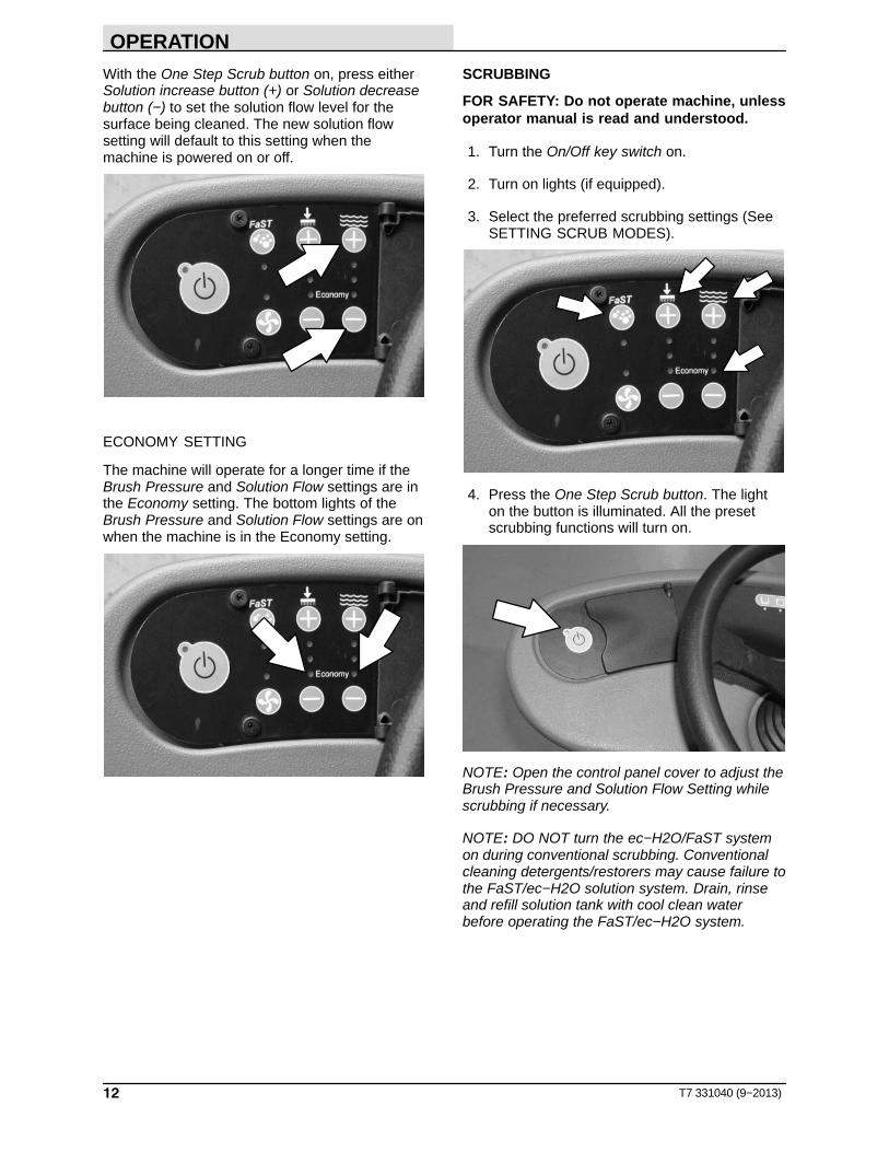
With the One Step Scrub button on, press eitherSolution increase button (+) or Solution decreasebutton (−) to set the solution flow level for thesurface being cleaned. The new solution flowsetting will default to this setting when themachine is powered on or off.
ECONOMY SETTING
The machine will operate for a longer time if theBrush Pressure and Solution Flow settings are inthe Economy setting. The bottom lights of theBrush Pressure and Solution Flow settings are onwhen the machine is in the Economy setting.
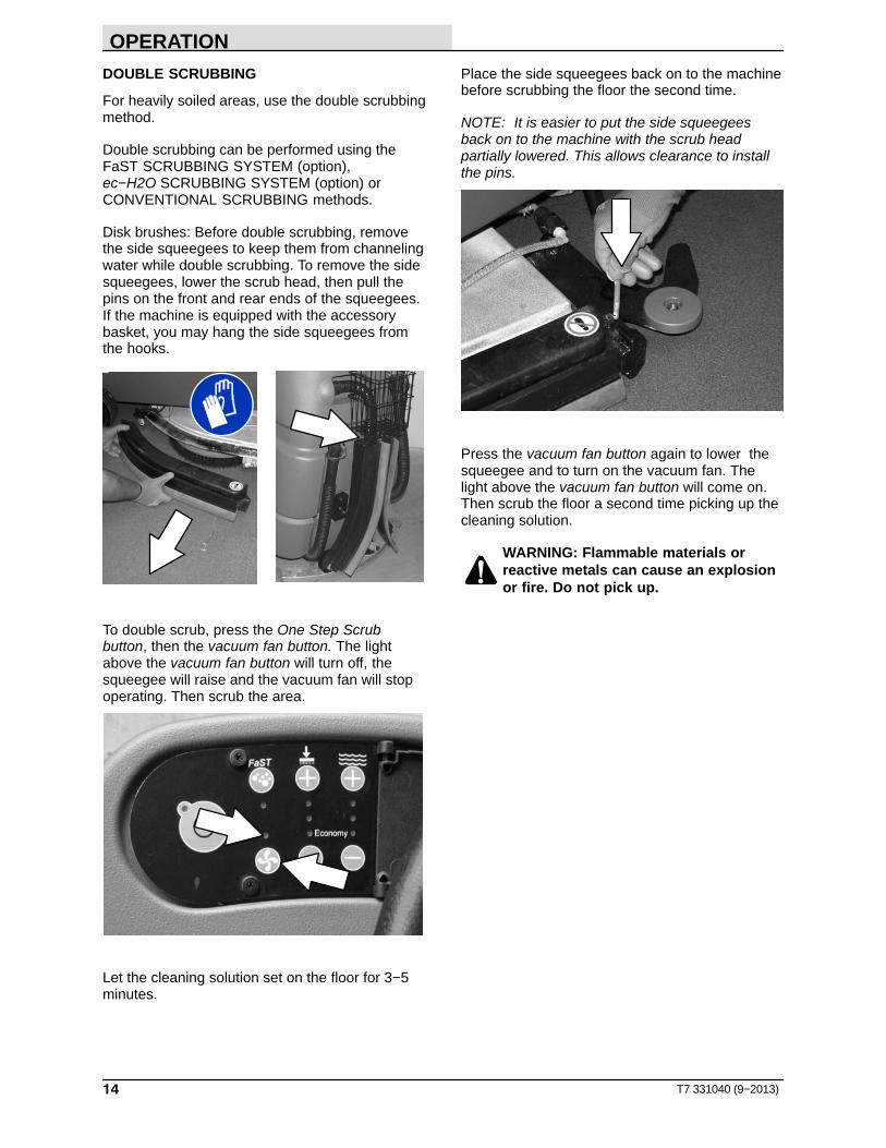
SCRUBBING
FOR SAFETY: Do not operate machine, unlessoperator manual is read and understood.
1. Turn the On/Off key switch on.
2. Turn on lights (if equipped).
3. Select the preferred scrubbing settings (SeeSETTING SCRUB MODES).
4. Press the One Step Scrub button. The lighton the button is illuminated. All the presetscrubbing functions will turn on.
NOTE: Open the control panel cover to adjust theBrush Pressure and Solution Flow Setting whilescrubbing if necessary.
NOTE: DO NOT turn the ec−H2O/FaST systemon during conventional scrubbing. Conventionalcleaning detergents/restorers may cause failure tothe FaST/ec−H2O solution system. Drain, rinseand refill solution tank with cool clean waterbefore operating the FaST/ec−H2O system.

OPERATION
13T7 331040 (9−2013)
5. Place the directional switch in the directionthe machine is to be moved (forward orreverse).
NOTE: The machine can scrub in both forward orreverse. The horn will sound when in reverse.
NOTE: The squeegee automatically raises whenthe machine is driven backwards. This preventsdamaging the squeegee. When the machine isplaced in reverse, the vacuum fan will shut offafter a short delay.
6. Press the propel pedal to begin scrubbing.
WARNING: Flammable materials orreactive metals can cause an explosionor fire. Do not pick up.
7. Release the propel pedal to stop the machine.Scrubbing functions stop and the automaticpark brake will engage when the machinestops.
8. The Brake pedal can be used to control themachine if quicker stopping is needed or ifoperating on an incline. Do not operatemachine on inclines exceeding 7% whenscrubbing.
FOR SAFETY: When using machine, go slowlyon inclines and slippery surfaces.
9. Press the One Step Scrub button to stopscrubbing. The light next to the One StepScrub button will turn off and the scrubbingfunctions will turn off after a short delay.
OPERATION
14 T7 331040 (9−2013)
DOUBLE SCRUBBING
For heavily soiled areas, use the double scrubbingmethod.
Double scrubbing can be performed using the FaST SCRUBBING SYSTEM (option), ec−H2O SCRUBBING SYSTEM (option) or CONVENTIONAL SCRUBBING methods.
Disk brushes: Before double scrubbing, removethe side squeegees to keep them from channelingwater while double scrubbing. To remove the sidesqueegees, lower the scrub head, then pull thepins on the front and rear ends of the squeegees.If the machine is equipped with the accessorybasket, you may hang the side squeegees fromthe hooks.
To double scrub, press the One Step Scrubbutton, then the vacuum fan button. The lightabove the vacuum fan button will turn off, thesqueegee will raise and the vacuum fan will stopoperating. Then scrub the area.
Let the cleaning solution set on the floor for 3−5minutes.
Place the side squeegees back on to the machinebefore scrubbing the floor the second time.
NOTE: It is easier to put the side squeegeesback on to the machine with the scrub headpartially lowered. This allows clearance to installthe pins.
Press the vacuum fan button again to lower thesqueegee and to turn on the vacuum fan. Thelight above the vacuum fan button will come on.Then scrub the floor a second time picking up thecleaning solution.
WARNING: Flammable materials orreactive metals can cause an explosionor fire. Do not pick up.

OPERATION
15T7 331040 (9−2013)
WATER PICKUP MODE (NO SCRUBBING)
The machine can be used to pick up water ornon−flammable liquid spills without scrubbing.
To pick up water or non−flammable liquid spills,check to make sure that the One Step Scrubbutton is not activated. The light next to the OneStep Scrub button must be off.
WARNING: Flammable materials orreactive metals can cause an explosionor fire. Do not pick up.
Then press the vacuum fan button. The lightabove the vacuum fan button will turn on, thesqueegee will lower and the vacuum fan will startoperating. Then pick up the water ornon−flammable liquid spill.
WHILE OPERATING THE MACHINE
Drive as straight a path as possible. Avoidbumping into posts or scraping the sides of themachine. Overlap the scrub paths by severalcentimeters (a few inches).
Avoid turning the steering wheel too sharply whenthe machine is in motion. The machine is veryresponsive to the movement of the steering wheel.Avoid sudden turns, except in emergencies.
When scrubbing dead end aisles, start at theclosed end of the aisle and scrub out towards theopening.
Adjust the machine speed, brush pressure, andsolution flow as required when scrubbing. Use theminimal brush pressure and solution flow settingsas possible.
Keep the machine moving to prevent damagingfloor finishes.
If poor scrubbing performance is observed, stopscrubbing and refer to MACHINETROUBLESHOOTING .
Conventional Scrubbing: Pour a recommendedfoam control solution into the recovery tank ifexcessive foam appears.
ec−H2O SCRUBBING: If an alarm sounds andthe ec−H2O system indicator light begins to blinkred, the ec−H2O module must be flushed toresume ec−H2O operation (See ec−H2OMODULE FLUSH PROCEDURE on page 37)
NOTE: When the alarm sounds and the lightblinks red, the machine will bypass the ec−H2Osystem. To continue scrubbing, turn the ec−H2Oswitch off and change over to conventionalscrubbing.
Change or rotate pads as necessary.
Observe the battery discharge indicator to ensurethere is adequate charge for machine operation.
Observe the solution tank indicator to ensure thesolution tank is not empty. Always empty recoverytank before refilling the solution tank.
Observe the recovery tank indicator to ensure therecovery is not full.
Remove the key when leaving the machineunattended.
Perform the Daily Maintenance Procedures afterscrubbing (see MACHINE MAINTENANCE).
Drive the machine slowly on inclines. Use thebrake pedal to control machine speed ondescending inclines. Scrub with the machine upinclines rather than down inclines.
FOR SAFETY: When using machine, go slowlyon inclines and slippery surfaces.

OPERATION
16 T7 331040 (9−2013)
Do not operate machine in areas where theambient temperature is above 43� C (110� F). Donot operate scrubbing functions in areas wherethe ambient temperature is below freezing 0� C(32� F).
The maximum rated incline for scrubbing with themachine is 7%. The maximum rated incline duringtransport of the machine is 19.25%.
EMERGENCY STOP BUTTON
The Emergency Stop Button halts all power to themachine in case of an emergency. Press thebutton to halt the machine power. To restart themachine, turn the Emergency Stop Button to theright. Then turn the on/off switch to the off positionand then to the on position.
NOTE: This button should not be used for normalstopping as premature wear to the parking brakemay occur.
HOUR METER
The hour meter records the number of hours themachine has been powered on. This informationis useful for servicing the machine. It is locatedunder the seat.
ec−H2O SYSTEM INDICATOR LIGHT
The ec−H2O system indicator light will not turn onuntil the machine starts scrubbing.
ec−H2O SYSTEM INDICATOR LIGHTCODE
CONDITION
Solid green Normal operation
Blinking red Flush ec−H2O module
Solid red Contact Service Center
ec−H2O SCRUBBING: If an alarm sounds andthe ec−H2O system indicator light begins to blinkred, the ec−H2O module must be flushed toresume ec−H2O operation (See ec−H2OMODULE FLUSH PROCEDURE on page 37)
NOTE: When the alarm sounds and the lightblinks red, the machine will bypass the ec−H2Osystem. To continue scrubbing, turn the ec−H2Oswitch off and change over to conventionalscrubbing.

OPERATION
17T7 331040 (9−2013)
SOLUTION TANK EMPTY INDICATOR
The solution tank empty indicator comes on whenthe solution tank is empty. When this happens,the scrub functions are disabled. If necessary,press the ONE STEP Scrub button for anadditional minute of operation to pick up standingwater or solution.
RECOVERY TANK FULL INDICATOR
The recovery tank full indicator comes on whenthe recovery tank is full. When this happens, thescrub functions are disabled. If necessary, pressthe ONE STEP Scrub button for an additionalminute of operation to pick up standing water orsolution.
BATTERY DISCHARGE INDICATOR
The battery discharge indicator shows the chargelevel of the batteries.
When the batteries are fully charged, all five lightsare lit. As the batteries discharge, the lights go outuntil only the left light is blinking.
When the left light blinks, the scrubbing functionswill shut off to alert the operator of the batterycondition. The machine will still propel when thelight is blinking. Recharge the batteries when thelight blinks. If necessary, press the ONE STEPScrub button for an additional minute of operationto pick up standing water or solution.
NOTE: Do not charge batteries more often thannecessary. Excessive charging could reduce thelife of the batteries. It is best to charge thebatteries only when the left light indicates that thebattery needs charging. See BATTERIES in theMAINTENANCE section.
NOTE: The blinking left battery discharge light willnot reset from blinking until the batteries are fullycharged.

OPERATION
18 T7 331040 (02−09)
FAULT INDICATOR
The fault indicator light (shown in upper right)comes on when there a fault is detected in thepropelling motor, vacuum fan motor, or brushmotors.
Refer to the table below to determine the causefor the fault or failure.
Indicator(s) Cause(s) RemedyFault Light blinks Propel motor is overloaded Contact Tennant service
representativeFault Light and top
Brush Pressure Lightboth blink
The right or rear Brush Motor isoverloaded (possibly from string or
banding wrapped around motor)
Remove string / banding from motoror Contact Tennant service
representativeFault Light and bottomBrush Pressure Light
both blink
The left or front Brush Motor isoverloaded (possibly from string or
banding wrapped around motor)
Remove string / banding from motoror Contact Tennant service
representativeFault Light and
Vacuum Fan Lightboth blink
Vacuum Fan Motor is overloaded Contact Tennant servicerepresentative

OPERATION
19T7 331040 (9−06)
CIRCUIT BREAKERS
Circuit breakers are resettable electrical circuitprotection devices that stop the flow of current inthe event of a circuit overload. Once a circuitbreaker is tripped, allow breaker to cool and thenpress the reset button to manually reset thebreaker.
If the overload that caused the circuit breaker totrip is still there, the circuit breaker will continue tostop current flow until the problem is corrected.
The circuit breakers are located inside the batterycompartment next to the hour meter.
The chart shows the circuit breakers and theelectrical components they protect.
CircuitBreaker Rating Circuit Protected
CB1 5 A Instrument Panel − power
CB2 15 A Accessories
FUSES
The fuse is a one-time protection device designedto stop the flow of current in the event of a circuitoverload. The 100 A fuse is located inside thebattery compartment near the hourmeter. Itprotects the propel circuit.
NOTE: Always replace the fuse with a fuse of thesame amperage.
HAZARD LIGHT SWITCH (OPTION)
The Hazard Light Switch operates the optionalhazard light.

OPERATION
20 T7 331040 (9−2013)
DRAINING AND CLEANING THE TANKS
When cleaning is finished, or when the recoverytank full indicator comes on, the recovery tankshould be drained and cleaned. The solution tankthen can be filled again for additional cleaning.
1. Drive the machine to a solution disposal drain.
2. Turn the machine ON/OFF key switch off.
FOR SAFETY: Before leaving or servicingmachine, stop on level surface, turn offmachine, and remove key.
3. Tilt the operator seat forward and hook theseat latch into place to hold up the seat.
4. Remove the recovery tank drain hose. Whileholding the hose up, remove the plug, thenslowly lower the drain hose to the floor drainor sink.
5. Lift the recovery tank cover. Flush the insideof the recovery tank with clean water.
WARNING: Flammable materials cancause an explosion or fire. Do not useflammable materials in tank(s).
NOTE: DO NOT use steam to clean tanks.Excessive heat can damage tanks andcomponents.
6. Rinse the float sensor located inside therecovery tank.
7. Replace the recovery tank drain hose cap andmount the drain hose back onto the mountingclip after the tank is drained.

OPERATION
21T7 331040 (9−2013)
8. Remove and clean the vacuum fan filter.Clean the filter with a damp cloth or lowpressure water hose if dirty. Allow the vacuumfan filter to dry completely before reinstalling itin the machine.
9. Close the recovery tank cover.
10. Remove the solution tank drain hose. Whileholding the hose up, remove the plug, thenslowly lower the drain hose to the floor drainor sink.
11. Tilt the recovery tank back to access thesolution tank. Make sure the recovery tank isempty before tilting.
12. Flush the solution tank and rinse the floatsensor located inside the back part of thesolution tank. Rinse the screen filter on thebottom of the tank.
13. Carefully push the recovery tank forward toclose the solution tank.
14. Unhook the seat latch and lower the operatorseat.
15. Clean the front of the solution tank throughthe front access port located under the frontsolution tank cover. Wipe the bottom of thecover and the tank seal before replacing thecover.

OPERATION
22 T7 331040 (9−2013)
16. Cylindrical scrub head: Remove and clean thedebris tray. Place the tray back in the scrubhead when finished.
17. Replace the solution tank drain hose cap andmount the drain hose back onto the mountingclip after after the tank is drained.
PROPEL SYSTEM TROUBLESHOOTING
The audio alarm (horn) will sound and/or warninglights will come on when a propelling system faultor failure is detected. The machine will stoppropelling when this happens. Refer to the tablebelow to determine the cause for the fault orfailure.
Indicator(s) Cause(s) RemedyHorn repeatedly
beeps 2 timesPropel pedal depressed without
operator in seatSit in seat when operating machine
Horn repeatedly beeps 4 times
ON/OFF key switch is turned on whilepropel pedal is engaged
Release the propel pedal beforeturning key on
Horn repeatedly beeps 5 times
Failure in the Throttle system hasoccurred
Contact Tennant servicerepresentative
Horn repeatedly beeps 6 times
Failure in the Brake system hasoccurred
Contact Tennant servicerepresentative
Horn repeatedly beeps 7 times
Failure in the Parking Brake systemhas occurred
Contact Tennant servicerepresentative
Horn repeatedly beeps 8 times
Emergency Stop Button is engaged Reset Emergency Stop Button
Horn repeatedly beeps 9 times
ON/OFF key switch is turned on whilebattery charger is plugged into
machine
Unplug battery charger before startingmachine
Fault Light blinks Propel motor is overloaded Contact Tennant servicerepresentative
OPERATION
23T7 331040 (02−09)
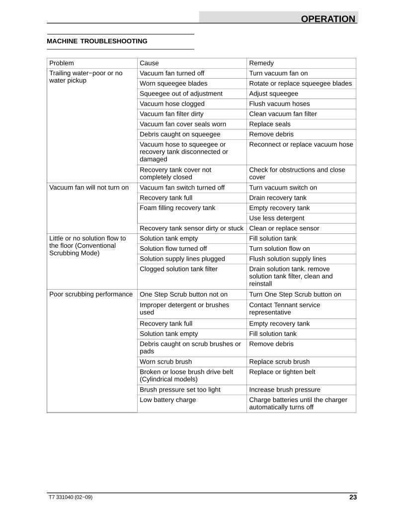
MACHINE TROUBLESHOOTING
Problem Cause Remedy
Trailing water−poor or nowater pickup
Vacuum fan turned off Turn vacuum fan on
Worn squeegee blades Rotate or replace squeegee blades
Squeegee out of adjustment Adjust squeegee
Vacuum hose clogged Flush vacuum hoses
Vacuum fan filter dirty Clean vacuum fan filter
Vacuum fan cover seals worn Replace seals
Debris caught on squeegee Remove debris
Vacuum hose to squeegee orrecovery tank disconnected ordamaged
Reconnect or replace vacuum hose
Recovery tank cover notcompletely closed
Check for obstructions and closecover
Vacuum fan will not turn on Vacuum fan switch turned off Turn vacuum switch on
Recovery tank full Drain recovery tank
Foam filling recovery tank Empty recovery tank
Use less detergent
Recovery tank sensor dirty or stuck Clean or replace sensor
Little or no solution flow tothe floor (ConventionalScrubbing Mode)
Solution tank empty Fill solution tank
Solution flow turned off Turn solution flow on
Solution supply lines plugged Flush solution supply lines
Clogged solution tank filter Drain solution tank. removesolution tank filter, clean andreinstall
Poor scrubbing performance One Step Scrub button not on Turn One Step Scrub button on
Improper detergent or brushesused
Contact Tennant servicerepresentative
Recovery tank full Empty recovery tank
Solution tank empty Fill solution tank
Debris caught on scrub brushes orpads
Remove debris
Worn scrub brush Replace scrub brush
Broken or loose brush drive belt(Cylindrical models)
Replace or tighten belt
Brush pressure set too light Increase brush pressure
Low battery charge Charge batteries until the chargerautomatically turns off

OPERATION
24 T7 331040 (02−09)
Problem Cause Remedy
FaST System does notoperate
FaST switch is turned off Turn on the FaST switch
Accessory circuit breaker tripped Reset circuit breaker
Clogged FaST−PAK supply hoseand/or connector
Soak connector and hose in warmwater and clean
FaST−PAK carton is empty or notconnected
Replace FaST−PAK carton and/orconnect supply hose
FaST system is not primed To prime, operate the FaST solu-tion system for a few minutes
Clogged solution tank filter Drain solution tank. removesolution tank filter, clean andreinstall
Clogged detergent injector See FaST SYSTEMMAINTENANCE
Faulty solution pump Replace solution pump
ec−H2O Model: ec−H2O system indicatorlight blinking red
Mineral deposit build−up in module Flush module (See ec−H2OMODULE FLUSH PROCEDUREon page 37)
ec−H2O Model: Alarm sounds
ec−H2O Model: ec−H2O system indicatorlight solid red
Defective module Contact Service Center
ec−H2O Model: ec−H2O system indicatorlight does not turn on
Defective light or module Contact Service Center
ec−H2O Model: No water flow
Clogged module Contact Service Center
Defective solution pump Replace solution pump

MAINTENANCE
25T7 331040 (02−09)
MAINTENANCE
1
1
2
8
3
9
11
5
4
3
6
310
7
10
3
12
13
14
355033
15

MAINTENANCE
26 T7 331040 (9−2013)
MAINTENANCE CHART
The table below indicates the Person Responsiblefor each procedure.O = Operator.T = Trained Personnel.
IntervalPersonResp. Key Description Procedure
Lubricant/Fluid
No. ofServicePoints
Daily O 1 Side and rearsqueegees
Check for damage and wear − 3Check deflection andleveling
− 6
O 2 Scrub brushes / pads Check for damage, wear,debris
− 2
O 8 Recovery tank Clean tank, screen filter, andfloat sensor
− 1
O 9 Vacuum fan filter Clean − 1O 7 FaST−PAK supply hose
and connector (option)Clean and connect hose tostoring plug when not in use
− 1
O 12 Debris tray (Cylindrical brushes)
Clean − 1
Weekly T 4 Battery cells (Lead acid batteries)
Check electrolyte level DW 3
50Hours
O 11 Disk scrub head floorskirt
Check for damage and wear − 2
O 13 Cylindrical brushes Check taper and rotate frontto rear
− 2
100Hours
T 3 Vacuum Fan and tankseals
Check for damage and wear − 3
T 14 Cylindrical brush drivebelts
Check tension − 2
200Hours
T 4 Battery terminals andcables
Check and clean − 12
500Hours
T 9 Vacuum fan motor(s) Check motor brushes(Check every 100 hoursafter initial 500 hourcheck)
− 1
T 5 Scrub brush motors Check motor brushes(Check every 100 hoursafter initial 500 hourcheck)
− 2
T 6 Propelling motor Check motor brushes(Check every 100 hoursafter initial 500 hourcheck)
− 1
T 10 Tires Check for damage and wear − 31000Hours
T 15 FaST water and airfilters (option)
Replace − 1
LUBRICANT/FLUID
DW Distilled water. . . .
NOTE: More frequent maintenance intervals may be required in extremely dusty conditions.

MAINTENANCE
27T7 331040 (9−2013)
BATTERIES
FOR SAFETY: Before leaving or servicingmachine, stop on level surface, turn offmachine, and remove key.
The lifetime of the batteries is limited to thenumber of charges the batteries receive. To getthe most life from the batteries, only recharge thebatteries when the battery discharge indicator isdown to the last bar. It’s also important tomaintain the proper electrolyte levels during thelife of the battery.
CHECKING THE ELECTROLYTE LEVEL (WET / LEAD ACID BATTERIES ONLY)
NOTE: Do Not check the electrolyte level if themachine is equipped with the battery wateringsystem. Proceed to HYDROLINK BATTERYWATERING SYSTEM (OPTION).
Check the battery electrolyte level weekly formachines equipped with wet/lead acid batteries.
08247
FOR SAFETY: When servicing machine, avoidcontact with battery acid.
The level should be slightly above the batteryplates as shown before charging. Add distilledwater if low. DO NOT OVERFILL. The electrolytewill expand and may overflow when charging.
Before Charging After Charging
NOTE: Make sure the battery caps are in placewhile charging.
CHECKING CONNECTIONS / CLEANING
After every 200 hours of use check for loosebattery connections and clean the surface of thebatteries, including terminals and cable clamps,with a strong solution of baking soda and water.Replace any worn or damaged wires. Do notremove battery caps when cleaning batteries.
Objects made of metal can potentially short circuitthe batteries. Keep all metallic objects off thebatteries.
GEL BATTERIES
Gel batteries do not require any maintenanceother than routine charging.

MAINTENANCE
28 T7 331040 (9−2013)
CHARGING THE BATTERIES WITHOFF−BOARD CHARGER
IMPORTANT: Before charging, make sure thatthe charger setting is properly set for thebattery type.
1. Drive the machine to a flat, dry surface.
NOTE: Make sure the area is well ventilated.
2. Turn the machine ON/OFF key switch off.
FOR SAFETY: Before leaving or servicingmachine, stop on level surface, turn offmachine, and remove key.
3. Tilt the operator seat forward and hook theseat latch into place to hold up the seat
NOTE: Make sure the batteries have the properelectrolyte level before charging. See CHECKINGTHE ELECTROLYTE LEVEL.
4. Plug the charger connector into the machinebattery charging connector.
WARNING: Batteries emit hydrogen gas.Explosion or fire can result. Keepsparks and open flame away. Keepcovers open when charging.
5. Plug the battery charger into the wall outlet.
NOTE: If the red “ABNORMAL CYCLE” lamplights when the TENNANT charger is plugged intoa wall outlet, the charger cannot charge thebattery and there is something wrong with thebattery.
07224
6. The TENNANT charger will startautomatically. When the batteries are fullycharged, the TENNANT charger willautomatically turn off.
NOTE: Do not disconnect he charger’s DC cordfrom the machine’s battery charging connectorwhen the charger is operating. Arcing may result.If the charger must be interrupted during charging,disconnect the AC power supply cord first.
7. After the charger has turned off, unplug thecharger from the machine battery chargingconnector.
8. Unhook the seat latch and lower the operatorseat.

MAINTENANCE
29T7 331040 (9−06)
CHECKING ON−BOARD BATTERY CHARGERSETTINGS
If your machine is equipped with the on−boardcharger, the charger settings must be set for yourbattery type before charging. Failure to properlyset will result in battery damage.
To determine your battery type, see battery label.Contact your battery supplier if not specified.
To verify the setting of the charger, connect thecharger cord into an electrical receptacle. Thecharger will display a sequence of codes. One ofthe codes will either read “GEL” or “Acd”.
GEL = Set for sealed/maintenance free batteries.Acd = Set for wet/lead acid batteries.
To change the settings to use a different type ofbattery, contact your Tennant Servicerepresentative.
CHARGING THE BATTERIES WITH THEON−BOARD CHARGER
NOTE: If your machine is equipped with theon−board battery charger, make sure that thecharger is properly set for your battery type beforecharging (See CHECKING ON−BOARDBATTERY CHARGER SETTINGS).
1. Drive the machine to a flat, dry surface.
NOTE: Make sure the area is well ventilated.
2. Turn the machine ON/OFF key switch off.
FOR SAFETY: Before leaving or servicingmachine, stop on level surface, turn offmachine, and remove key.
3. Tilt the operator seat forward and hook theseat latch into place to hold up the seat
WARNING: Batteries emit hydrogen gas.Explosion or fire can result. Keepsparks and open flame away. Keepcovers open when charging.
4. Connect the charger’s AC power supply cordinto a properly grounded wall outlet.

MAINTENANCE
30 T7 331040 (06−06)
5. The charger will display a sequence of codesonce the cord is connected. Three−digits + the following code:
A = Charging currentU = Battery Voltageh = Charging timeC = Charging ampere−hours [Ah]E = Energy used [Kwh]
6. Press the arrow button to review the codes.
Once the charging cycle begins, the indicatorlights will progress from red, yellow to green.When the green indicator light comes on, thecharging cycle is done. Unplug the charger cord.
If the charger detects a problem, the charger willdisplay an error code. See ON−BOARDBATTERY CHARGER ERROR CODES.
ON−BOARD BATTERY CHARGER ERROR CODES
DISPLAY CODE FAULT SOLUTION
bat Loose or damaged battery cable Check battery cable connections.
Battery exceeded maximum volt-age level.
No action necessary.
E01 Exceeded maximum battery volt-age allowed.
No action necessary.
E02 Safety thermostat exceededmaximum internal temperature.
Check if the charger vents are obstructed.
E03 Exceeded maximum time forcharging phase leaving the batter-ies undercharged due to a sulfatedor faulty battery.
Repeat the charging cycle and if the errorcode E03 reappears check battery orreplace it.
SCt Safety timer exceeded maximumcharging time. Interrupts chargingcycle.
Replace battery.
Srt Possible internal short circuit. Contact Service Center.

MAINTENANCE
31T7 331040 (9−2013)
ELECTRIC MOTORS
FOR SAFETY: Before leaving or servicingmachine, stop on level surface, turn offmachine, and remove key.
The carbon brushes on the vacuum fan motor, thepropelling motor, and the scrub brush motorsshould be inspected after the initial 500 hours ofmachine operation and then every 100 hours afterthe initial 500 hours.
BELTS (Cylindrical Models)
FOR SAFETY: Before leaving or servicingmachine, stop on level surface, turn offmachine, and remove key.
The two brush drive belts are located on thecylindrical brush scrub head. The belts drive thecylindrical brushes. Proper belt tension is a 6 mm(0.25 in) deflection from a force of 2.3 to 2.5 kg(5.0 to 5.4 lb) at the belt midpoint.
Check and adjust the belt tension every 100 hoursof operation.

MAINTENANCE
32 T7 331040 (9−2013)
SCRUB BRUSHES AND PADS
The machine can be equipped with either disk orcylindrical scrub brushes, or cleaning pads. Checkscrub brushes daily for wire or string tangledaround the brush or brush drive hub. Also checkfor brushes damage and wear.
DISK BRUSHES
The scrub brushes should be replaced if a largenumber of bristles are missing or if bristle length isless than 10 mm (0.38 in).
Cleaning pads must be placed on pad drivesbefore they are ready to use. The cleaning pad isheld in place by a pad holder.
Cleaning pads need to be cleaned immediatelyafter use with soap and water. Do not wash thepads with a pressure washer. Hang pads, or liepads flat to dry.
NOTE: Always replace brushes and pads in sets.Otherwise one brush or pad will be moreaggressive than the other.
REPLACING DISK BRUSHES OR PAD DRIVER
1. Stop machine on a level surface. Make surethe scrub head is in the raised position.
2. Turn the machine ON/OFF key switch off.
FOR SAFETY: Before leaving or servicingmachine, stop on level surface, turn offmachine, and remove key.
3. Pull the pin from the side squeegee retainerpivot.
4. Open the side squeegee retainer pivot towardthe front of the machine, then pull the sidesqueegee toward the rear of the machine toaccess the scrub brushes or pads.

MAINTENANCE
33T7 331040 (9−2013)
5. Pull the scrub brush/pad driver downward toremove it from the drive hub.
6. Place the new scrub brush/pad driver onto thedrive hub. Ensure that it is securely mountedonto the brush drive hub.
7. Close the side squeegee and the retainerpivot, then insert the pin.
NOTE: Be sure the pin is inserted completelythrough the bottom.
REPLACING DISK PADS
1. Remove the pad driver from the machine.
2. Squeeze the spring clip together to removethe center disk.
3. Flip or replace the scrub pad, center the scrubpad on the pad driver. Then reinstall thecenter disk to secure the pad in place on thepad driver.
4. Reinsert the pad driver into the machine.
MAINTENANCE
34 T7 331040 (9−2013)
CYLINDRICAL BRUSHES
Check the brush taper and rotate the brushesfrom front-to-rear every 50 hours of machineoperation for maximum brush life and bestscrubbing performance.
The cylindrical brushes should be replaced if largeamounts of bristles are missing, or if theremaining bristle length is less than 15 mm (0.62 in).
NOTE: Replace worn brushes in pairs. Scrubbingwith brushes of unequal bristle length will result indiminished scrubbing performance.
REPLACING OR ROTATING CYLINDRICALBRUSHES
1. Stop machine on a level surface. Make surethe scrub head is in the raised position.
2. Turn the machine ON/OFF key switch off.
FOR SAFETY: Before leaving or servicingmachine, stop on level surface, turn offmachine, and remove key.
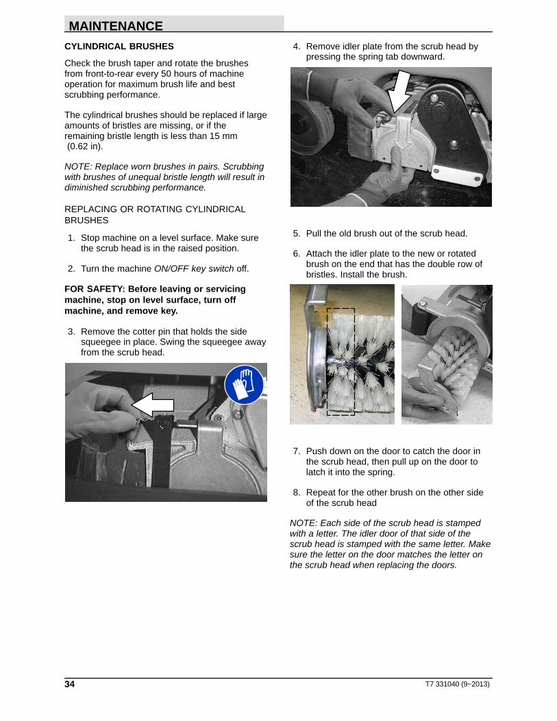
3. Remove the cotter pin that holds the sidesqueegee in place. Swing the squeegee awayfrom the scrub head.
4. Remove idler plate from the scrub head bypressing the spring tab downward.
5. Pull the old brush out of the scrub head.
6. Attach the idler plate to the new or rotatedbrush on the end that has the double row ofbristles. Install the brush.
7. Push down on the door to catch the door inthe scrub head, then pull up on the door tolatch it into the spring.
8. Repeat for the other brush on the other sideof the scrub head
NOTE: Each side of the scrub head is stampedwith a letter. The idler door of that side of thescrub head is stamped with the same letter. Makesure the letter on the door matches the letter onthe scrub head when replacing the doors.

MAINTENANCE
35T7 331040 (9−2013)
CHECKING CYLINDRICAL BRUSH PATTERN
1. Apply chalk, or a similar marking material, toa smooth and level section of the floor.
NOTE: If chalk or other material is not available,allow the brush to spin on the floor for twominutes. A polish mark will remain on the floor.
2. Raise the scrub head, then position thebrushes over the chalked area.
3. Block the front or rear wheels to prevent themachine from moving.
4. Lower the scrub head in the chalked area andslowly press the propel pedal until the scrubbrushes start spinning. Allow the machine toscrub in the same place for 15 to 20 seconds.
5. Raise the scrub head and drive the machineaway from the chalked area.
FOR SAFETY: Before leaving or servicingmachine, stop on level surface, turn offmachine, and remove key.
6. Observe the brush patterns. If the brushpattern is the same width across the entirelength of each brush and both brushes are thesame width, no adjustment is necessary.
10355
7. If the brush patterns are tapered, seeADJUSTING CYLINDRICAL BRUSH TAPERsection of this manual.
10652
8. If the width of the brushes is not the same,see ADJUSTING CYLINDRICAL BRUSHWIDTH section of this manual.
10653

MAINTENANCE
36 T7 331040 (9−2013)
ADJUSTING CYLINDRICAL BRUSH TAPER
1. Stop machine on a level surface. Make surethe scrub head is in the raised position.
2. Turn the machine ON/OFF key switch off.
FOR SAFETY: Before leaving or servicingmachine, stop on level surface, turn offmachine, and remove key.
3. Remove the cotter pin that holds the sidesqueegee in place. Swing the squeegee awayfrom the scrub head.
4. Remove idler plate from the scrub head bypressing the spring tab downward.
5. While holding the flat end of the idler shaftwith a wrench, loosen the mounting screw onthe outside of the idler door.
6. Turn the idler shaft to raise or lower the end ofthe brush as needed to straighten the brushpattern. Tighten the mounting screw.
7. Check the brush patterns again and readjustas necessary until both patterns are thesame.

MAINTENANCE
37T7 331040 (9−2013)
ADJUSTING CYLINDRICAL BRUSH WIDTH
1. Stop machine on a level surface. Make surethe scrub head is in the lowered position.
2. Turn the machine ON/OFF key switch off.
FOR SAFETY: Before leaving or servicingmachine, stop on level surface, turn offmachine, and remove key.
3. Loosen the two scrub head mounting screws.
4. Loosen the jam nut, then adjust the brushwidth adjustment screw. Tighten the jam nutand the two scrub head mounting screwswhen finished.
5. Check the brush patterns again and readjustas necessary until both brush patterns are thesame.

MAINTENANCE
38 T7 331040 (9−2013)
FaST SYSTEM MAINTENANCE (FaST Model)
FOR SAFETY: Before leaving or servicingmachine, stop on level surface, turn offmachine, and remove key.
Every 1000 hours replace the water filter and airfilter located in the FaST detergent injector. Orderfilter kit p/n 9003009.
1. To access the detergent injector assembly,lower the scrub head. The injector assemblyis located on top of the scrub head.
new photo
Disk ModelCylindrical BrushModel
2. Remove the injector assembly from the pinchclamps.
3. Replace the water and air filter. An 8mm hexwrench is required to install the new water filter.
Water Filter (50 Mesh/Brown)
Air Filter (50 Mesh/Brown)
FaST SUPPLY HOSE CONNECTOR
The FaST supply hose connector is located belowthe FaST−PAK holder. Soak the connector inwarm water if detergent buildup is visible. When aFaST−PAK carton is not installed, store thesupply hose connector on the storing plug toprevent the hose from clogging.
MAINTENANCE
39T7 331040 (9−2013)
ec−H2O SYSTEM (ec−H2O Model)
ec−H2O MODULE FLUSH PROCEDURE
This procedure is only required when an alarmsounds and the ec−H2O system indicator lightbegins to blink red.
FOR SAFETY: Before leaving or servicingmachine, stop on level surface and turn offmachine.
1. Drain the solution tank and recovery tank ofall water.
2. Pour 2 gallons (8 liters) of white or ricevinegar into the solution tank at full strength.Do not dilute. Use the rear fill port whenadding vinegar. Do not use the front fill port.
NOTE: Use white or rice vinegar only. Theacidity level should be between 4−8%. Do notuse other acids for this procedure.
3. Disconnect the black connector fitting at thescrub head and place the hose into a bucket.
4. Turn the key to the on position.
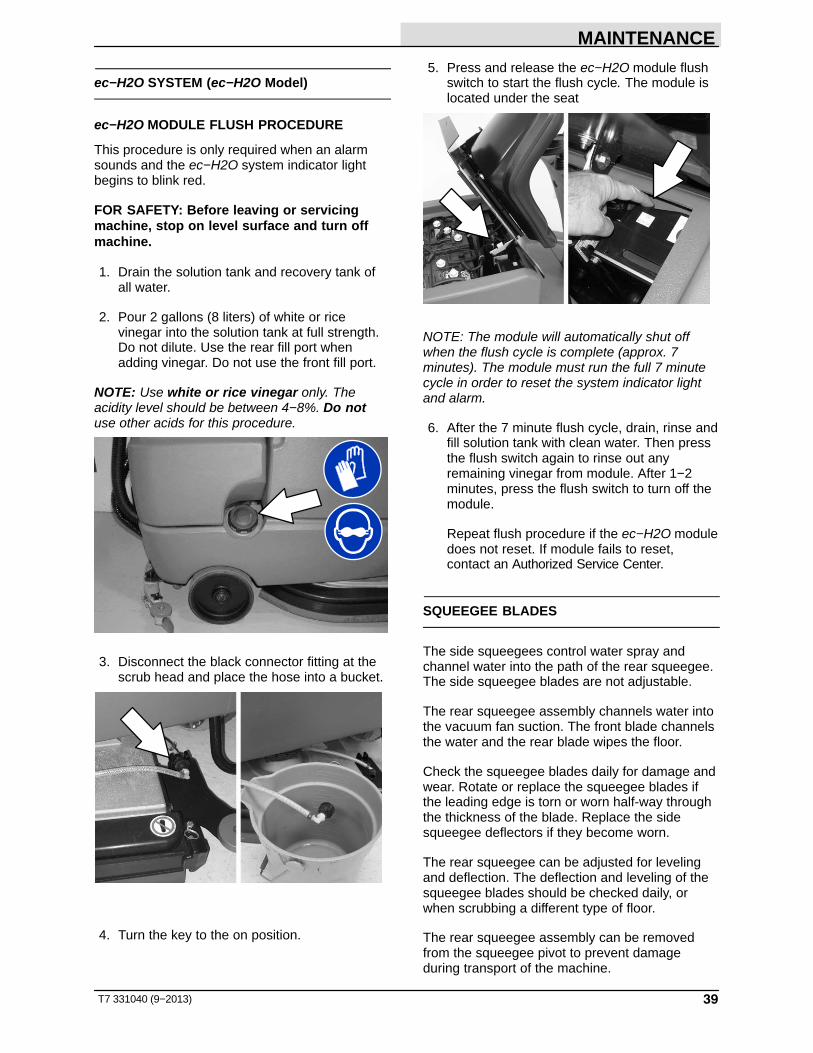
5. Press and release the ec−H2O module flushswitch to start the flush cycle. The module islocated under the seat
NOTE: The module will automatically shut offwhen the flush cycle is complete (approx. 7minutes). The module must run the full 7 minutecycle in order to reset the system indicator lightand alarm.
6. After the 7 minute flush cycle, drain, rinse andfill solution tank with clean water. Then pressthe flush switch again to rinse out anyremaining vinegar from module. After 1−2minutes, press the flush switch to turn off themodule.
Repeat flush procedure if the ec−H2O moduledoes not reset. If module fails to reset,contact an Authorized Service Center.
SQUEEGEE BLADES
The side squeegees control water spray andchannel water into the path of the rear squeegee.The side squeegee blades are not adjustable.
The rear squeegee assembly channels water intothe vacuum fan suction. The front blade channelsthe water and the rear blade wipes the floor.
Check the squeegee blades daily for damage andwear. Rotate or replace the squeegee blades ifthe leading edge is torn or worn half-way throughthe thickness of the blade. Replace the sidesqueegee deflectors if they become worn.
The rear squeegee can be adjusted for levelingand deflection. The deflection and leveling of thesqueegee blades should be checked daily, orwhen scrubbing a different type of floor.
The rear squeegee assembly can be removedfrom the squeegee pivot to prevent damageduring transport of the machine.

MAINTENANCE
40 T7 331040 (9−2013)
REPLACING (OR ROTATING) THE REARSQUEEGEE BLADES
1. Stop machine on a level surface. Make surethe scrub head is in the raised position.
2. Turn the machine ON/OFF key switch off.
FOR SAFETY: Before leaving or servicingmachine, stop on level surface, turn offmachine, and remove key.
3. Remove the squeegee suction hose from therear squeegee assembly. Then loosen bothrear squeegee assembly mounting knobs.
4. Pull the rear squeegee assembly from themachine.
5. Loosen the rear squeegee retaining bandtension latch and remove the retaining band.
6. Remove rear squeegee blade from the rearsqueegee assembly.
7. Loosen the two outer knobs on the rearsqueegee assembly. Remove the frontsqueegee blade from the squeegee assembly.
8. Install the new front squeegee blade or rotatethe existing blade to the new edge. Be surethe holes in the front squeegee blade arehooked onto the tabs on the front bladeclamp.
9. Lightly tighten the two outer knobs.

MAINTENANCE
41T7 331040 (9−2013)
10. Install the new rear squeegee blade or rotatethe existing blade to the new edge. Be surethe holes in the squeegee blade are hookedonto the tabs on the squeegee assembly.
11. Reinstall the rear squeegee retaining bandonto the squeegee assembly. Be sure each ofthe flanges on the retaining band are seatedin the cut outs in the rear squeegee assembly.
12. Tighten the rear squeegee retaining bandtension latch.
13. Reinstall the rear squeegee under thesqueegee mount bracket and tighten all fourknobs.
14. Reinstall the squeegee suction hose onto therear squeegee assembly.
REPLACING SIDE SQUEEGEE BLADES
FOR SAFETY: Before leaving or servicingmachine, stop on level surface, turn offmachine, and remove key.
1. Open the side squeegee.
2. Pull the old side squeegee blade from theside squeegee retainer. Slide the new bladeonto the retainer.
3. Close the side squeegee.

MAINTENANCE
42 T7 331040 (9−2013)
ADJUSTING THE SQUEEGEE GUIDE ROLLER
FOR SAFETY: Before leaving or servicingmachine, stop on level surface, turn offmachine, and remove key.
The squeegee guide rollers are located on bothends of the rear squeegee. The rollers guide thesqueegee blade end along a wall. Loosen the nutlocated at the top of the guide roller and move theroller in or out to adjust how close the end of thesqueegee blade is to the wall. The squeegeeblade end should be further away from the wallwhen the floor curves up into the wall.
LEVELING THE REAR SQUEEGEE
Leveling of the squeegee assures the entirelength of the squeegee is in even contact with thesurface being scrubbed. Perform this adjustmenton an even and level floor.
1. Lower the squeegee and drive the machineforward a few feet.
2. Turn off the machine ON/OFF key switch.
FOR SAFETY: Before leaving or servicingmachine, stop on level surface, turn offmachine, and remove key.
3. Look at the deflection of the squeegee overthe full length of the squeegee blade.
4. If the deflection is not the same over the fulllength of the blade, turn the squeegeeleveling bolt to make adjustments.
The squeegee leveling bolt is located directlybehind the squeegee suction hose. DO NOTdisconnect the suction hose from thesqueegee frame when leveling squeegee.
Turn the squeegee leveling boltcounter-clockwise to increase the deflection atthe ends of the squeegee.
Turn the squeegee leveling bolt clockwise todecrease the deflection at the ends of thesqueegee blade.
5. Drive the machine forward with the squeegeedown to recheck the squeegee bladedeflection if adjustments were made.
6. Readjust the squeegee blade deflection ifnecessary.

MAINTENANCE
43T7 331040 (9−2013)
ADJUSTING REAR SQUEEGEE BLADEDEFLECTION
Deflection is the amount of curl the overallsqueegee blade has when the machine movesforward. The best deflection is when thesqueegee wipes the floor dry with a minimalamount of deflection.
1. Lower the squeegee and drive the machineforward a few meters (feet).
2. Turn off the machine ON/OFF key switch.
FOR SAFETY: Before leaving or servicingmachine, stop on level surface, turn offmachine, and remove key.
3. Look at the amount of deflection or “curl” ofthe squeegee blade. The correct amount ofdeflection is 12 mm (0.50 in) for scrubbingsmooth floors and 15 mm (0.62 in) for roughfloors.
03719
12 mm(0.50 in)
4. If the overall squeegee blade deflection needsto be adjusted, loosen the jam nuts on thesqueegee casters and adjust the height.
5. Drive the machine forward again to recheckthe squeegee blade deflection afteradjustments are made.
6. Readjust the squeegee blade deflection ifnecessary.

MAINTENANCE
44 T7 331040 (9−2013)
SKIRTS AND SEALS
DISK SCRUB HEAD FLOOR SKIRT
FOR SAFETY: Before leaving or servicingmachine, stop on level surface, turn offmachine, and remove key.
The skirt is located in front of the disc brush scrubheads. Check the skirt for damage and wear afterevery 50 hours of operation.
The skirts should clear the floor by 0 to 6 mm (0 to .25 in) when the scrub brushes are new andthe scrub head is down.
RECOVERY TANK SEAL
FOR SAFETY: Before leaving or servicingmachine, stop on level surface, turn offmachine, and remove key.
The recovery tank seal is located on the bottom ofthe recovery tank cover. Check the seal fordamage and wear after every 100 hours ofoperation.
SOLUTION TANK SEALS
FOR SAFETY: Before leaving or servicingmachine, stop on level surface, turn offmachine, and remove key.
There are two solution tank seals. Check the sealfor damage and wear after every 100 hours ofoperation.
A front seal is located on the bottom of thesolution tank cover. A rear seal is located on thebottom of the recovery tank.
TIRES
FOR SAFETY: Before leaving or servicingmachine, stop on level surface, turn offmachine, and remove key.
The machine has three solid rubber tires: one tireis front and two are in the rear. Check the tires fordamage and wear after every 500 hours ofoperation.

MAINTENANCE
45T7 331040 (9−2013)
PUSHING, TOWING, AND TRANSPORTINGTHE MACHINE
PUSHING OR TOWING THE MACHINE
If the machine becomes disabled, it can bepushed from the front or rear, but only tow it fromthe front.
FOR SAFETY: When servicing machine, donot push or tow the machine on inclines withthe brake disabled.
Before attempting to push or tow the machine,disengage the brake as described below.
To disengage the brake, insert the tip of a smallscrew driver between the electronic brake leverand the hub.
For models manufactured before serial number10263298, the propel motor harness connectormust also be disconnected.
Only push or tow the machine on a level surface.Do not exceed 3.2 kp/h (2 mph). It is NOTintended to be pushed or towed at a high speed.
Immediately after pushing or towing the machine,remove the screw driver to enable the parkingbrake.
FOR SAFETY: Do not operate machine withthe brake disabled.
TRANSPORTING THE MACHINEWhen transporting the machine by trailer or truck,be certain to follow the tie−down procedure below:
1. Raise the squeegee and scrub head.
FOR SAFETY: When loading/unloadingmachine onto/off truck or trailer, drain tanksbefore loading machine.
2. Load the machine using a ramp that cansupport the machine weight and operator. Donot operate the machine on a ramp inclinethat exceeds 19.25%.
FOR SAFETY: When transporting machine,use a recommended ramp when loading/unloading into/off truck or trailer.
3. Position the front of machine against the frontof the trailer or truck.
4. Lower the scrub head and squeegee after themachine is positioned on the trailer or truck.
5. Place a block behind each wheel to preventthe machine from rolling.
6. Route the front tie−down straps through thestabilizer arms and then secure the tie−downsto the trailer or truck to prevent the machinefrom tipping.
NOTE: It may be necessary to install tie-downbrackets to the floor of the trailer or truck.
FOR SAFETY: When transporting machine,use tie−down straps to secure machine totruck or trailer.
7. Route the rear tie−down straps through theopening at the center part of the rear axle.

MAINTENANCE
46 T7 331040 (9−2013)
MACHINE JACKING
FOR SAFETY: Before leaving or servicingmachine, stop on level surface, turn offmachine, and remove key.
Empty the recovery and solution tanks beforejacking the machine. Jack up the machine forservice at the designated locations. Use a hoist orjack capable of supporting the weight of themachine. Always stop the machine on a flat, levelsurface and block the tires before jacking up themachine.
Front jacking locations are located on both sidesof the machine.
Rear jacking locations are located on both sidesof the machine at the axles.
FOR SAFETY: When servicing machine, blockmachine tires before jacking machine up. Usea hoist or jack that will support the weight ofthe machine. Jack machine up at designatedlocations only. Block machine up with jackstands.
STORAGE INFORMATION
The following steps should be taken when storingthe machine for extended periods of time.
1. Drain and clean the solution and recoverytanks. Open the recovery tank cover topromote air circulation.
2. Park the machine in a cool, dry area. Do notexpose the machine to rain. Store indoors.
3. Remove the batteries, or charge them everythree months.
FREEZE PROTECTION
FOR SAFETY: Before leaving or servicingmachine, stop on level surface and turn offmachine.
1. Drain the solution tank and recovery tank ofall water.
2. Pour 2 gallons (8 liters) of Propylene GlycolBased / Recreational Vehicle (RV) antifreezeinto the solution tank at full strength. Do notdilute.
3. FaST models: Remove the FaST−PAK andstore in temperatures above freezing.
FOR SAFETY: Avoid eye contact withantifreeze. Wear safety glasses.
4. Turn the machine power on and operate thesolution flow system. Turn the machine offwhen the antifreeze appears at the scrubhead.
Continue with the freeze protection procedure ifmachine is equipped with the ec−H2O system.
ec−H2O Model:
5. Press and release the flush switch on theec−H2O module to cycle the antifreezethrough ec−H2O system. When the antifreezeappears at the scrub head, press the switchagain to turn off the module.
IMPORTANT: Before operating machine, theantifreeze must be flushed from the module asdescribed below.
If the antifreeze is not properly flushed from theec−H2O system, the ec−H2O module may detectan error and not function (ec−H2O switchindicator light will turn red). If this occurs, resetkey and repeat the flush procedure as describedbelow.

MAINTENANCE
47T7 331040 (9−2013)
FLUSHING ANTIFREEZE FROM ec−H2OMODULE:
FOR SAFETY: Before leaving or servicingmachine, stop on level surface and turn offmachine.
1. Drain the antifreeze from the solution tankinto a bucket.
2. Fill the solution tank with cool water until full(See FILLING THE SOLUTION TANK).
3 Disconnect the black connector fitting at thescrub head and place the hose into a bucket.
4. Press and release the ec−H2O module flushswitch to start the flush cycle. The module islocated under the seat.
When the water turns clear, press the moduleswitch again to stop the flush cycle.
Dispose the antifreeze in an environmentally safeway according to local waste disposal regulations.
5. The machine is now ready for scrubbing.

SPECIFICATIONS
T7 331040 (9−2013)48
SPECIFICATIONS
GENERAL MACHINE DIMENSIONS/CAPACITIES
Item Disk 650 mm (26 in)
Cylindrical 700 mm (28 in)
Disk 800 mm (32 in)
Cylindrical 800 mm (32 in)
Length 1520 mm (60 in)
Height 1270 mm (50 in)
Width / frame 740 mm (29 in) 810 mm (31.7 in) 740 mm (29 in) 810 mm (31.7 in)
Width / machine withscrub head
800 mm (31.5 in) 830 mm (32.5 in) 910 mm (36 in) 930 mm (36.5 in)
Width / rear squeegee (roller to roller)
850 mm (33.25 in)
850 mm (33.25 in)
1000 mm (39.25 in)
1000 mm (39.25 in)
Brush diameter 330 mm (13 in) 150 mm (6 in) 410 mm (16 in) 150 mm (6 in)
Brush length − 700 mm (28 in) − 800 mm (32 in)
Scrubbing path width 650 mm (26 in) 700 mm (28 in) 800 mm (32 in) 800 mm (32 in)
Solution tank capacity 110 L (29 gallons)
Recovery tank capacity 110 L (29 gallons)
Weight/net less batteries 265 Kg (585 lbs) 287 kg (632 lbs) 265 Kg (585 lbs) 296 kg (653 lbs)
Weight/with standardbattery package
386 Kg (850 lbs) 407 kg (897 lbs) 386 Kg (850 lbs) 416 kg (918 lbs)
Weight/with heavy dutybattery package
443 Kg (975 lbs) 464 kg (1022 lbs) 443 Kg (975 lbs) 473 kg (1043 lbs)
GVWR 675 Kg (1485 lbs)
Protection Grade IPX3
Values determined as per EN 60335−2−72 Disk 650 mm
Cylindrical 700 mm
Disk 800 mm
Cylindrical 800 mm
Sound pressure level LpA 69 dB(A) 75 dB(A) 69 dB(A) 75 dB(A)
Sound uncertainty KpA 3.5 dB(A) 3.0 dB(A) 3.5 dB(A) 3.0 dB(A)
Sound power level LWA + Uncertainty KWA 85 dB(A) 87 dB(A) 85 dB(A) 87 dB(A)
Vibration − Hand−arm 0.139 m/s2 0.070 m/s2 0.139 m/s2 0.070 m/s2
Vibration − Whole body 0.045 m/s2 0.023 m/s2 0.045 m/s2 0.023 m/s2
Vibration uncertainty K 0.040 m/s2 0.080 m/s2 0.040 m/s2 0.080 m/s2
GENERAL MACHINE PERFORMANCE
Item Measure
Aisle turnaround width for 650 mm (26 in) scrub head 1730 mm (68.5 in)
Aisle turnaround width for 800 mm (32 in) scrub head 1840 mm (72.5 in)
Travel Speed (maximum) 6.4 Km/h (4 mph)
Maximum rated climb and descent angle with full tanks 10.5%
Maximum rated climb and descent angle with empty tanks 19.25%
Maximum rated climb and descent angle when scrubbing 7%

SPECIFICATIONS
49T7 331040 (02−09)
POWER TYPE
Type Quantity Volts Ah Rating Weight (Each)
Batteries (standard lead acid) 4 6 235 @ 20 hr rate 30.0 kg (66 lb)
Batteries (heavy duty aead acid) 4 6 335 @ 20 hr rate 44.5 kg (97.5 lb)
Batteries (Gel) 4 6 180 @ 20 hr rate 30.0 kg (66 lb)
Batteries (heavy duty Gel) 4 6 220 @ 20 hr rate 30.0 kg (66 lb)
Type Use VDC kW (hp)
Electric Motors Scrub brush (Disk) 24 0.45 kW (0.6 hp)
Scrub brush (Cylinderical) 24 0.50 kW (0.75 hp)
Vacuum fan 24 0.45 kW (0.6 hp)
Propelling 24 0.85 kW (1.1 hp)
Type VDC amp Hz Phase VAC
Chargers (Smart) 24 20 60 1 120
24 25 60 1 120
Chargers (Gel/Agm) 24 20 60 1 120
24 20 50 / 60 1 240
Chargers (On−Board) 24 25 50 / 60 1 115
TIRES
Location Type Size
Front (1) Solid 90 mm wide x 260 mm OD (3.5 in wide x 10 in OD)
Rear (2) Solid 80 mm wide x 260 mm OD (3.0 in wide x 10 in OD)
FaST SYSTEM (OPTION)
Item Measure
Solution pump 24 Volt DC, 5A, 5.7 LPM (1.5 GPM) open flow,70 psi bypass setting
Solution flow rate 1.1 LPM (0.30 GPM)
Detergent to water dilution ratio 1:1000
Detergent flow rate 1.35 CC/Minute (0.046 Ounces/Minute)
ec−H2O SYSTEM (OPTION)
Item Measure
Solution pump 24 Volt DC, 5A, 5.7 LPM (1.5 GPM) open flow,70 psi bypass setting
Solution flow rate* 1.1 L/min (0.30 gpm) Disk model
1.5 L/min (0.40 gpm) Cylindrical brush model
1.9 L/min (0.50 gpm) Optional
* If the optional solution flow rates are required, contact an Authorized Service Center.

SPECIFICATIONS
T7 331040 (9−06)50
Frame (Cyl)810 mm (31.7 in)
1270 mm(50 in)
1520 mm(60 in)
For 650 mm (26 in) and 700 mm (28 in) squeegee800 mm (33.25 in)
For 800 mm (32 in) squeegee1000 mm (39.25 in)
Frame (Disk)740 mm (29 in)
1014751
MACHINE DIMENSIONS

INDEX
51T7 331040 (9−2013)
A
Adjusting cylinderical brush taper, 36
Adjusting cylinderical brush width, 37
Adjusting Rear Squeegee Blade Deflection, 43
Adjusting the Squeegee Guide Roller, 42
Attaching the Squeegee Assembly, 9
Audio Alarms (Horn), 22
B
Batteries, 27Charging the Batteries, 28, 29Checking connections / cleaning, 27Checking the electrolyte level, 27Gel Batteries, 27Maintenance, 27Specifications, 49
Battery Charger, Error codes, 30
Battery Discharge Indicator, 17
Before Operating, 10
Belts, 31
Belts (Cylinderical Models), Inspect Belts, 31
Brush Information, 8Available Scrub Head Widths, 7
Brush pattern, Checking cylinderical , 35
Brush taper, Adjusting cylinderical , 36
Brush width, Adjusting cylinderical , 37
Brush, Replacing, 32
Brushes and Pads, 32
C
Capacities, 48
Charger, Checking on−board charger settings, 29
Charger error codes, 30
Charger setings, 29
Charging the Batteries, 28, 29
Checking on−board charger settings, 29
Checking cylinderical brush pattern, 35
Circuit Breakers, 19
Contents, 1
Controls and Instruments, 6
Conventional Scrubbing, 7
Cylindrical brushes, 34
D
Debris tray, 10, 22
Dimensions, 48
Disk brushes, 32
Disk Scrub Head Floor Skirt, 44
Double Scrubbing, 14
Draining and Cleaning the Tanks, 20
E
ec−H2O System Indicator Light, 11, 16
ec−H2O System Troubleshooting, 24
ec−H2O, System, 39
ec−H2O Alarm, 11
ec−H2O Button, 11
ec−H2O Scrubbing (ec−H2O Model), 8
ec−H2O System, 39
Economy Setting, 12
Electric Motors, 31Inspect Electric Motors, 31
Electrical system, BatteriesChecking connections / cleaning, 27Checking the electrolyte level, 27
Emergency Stop Button, 16
Error codes, batttery charger, 30
F
FaST Supply Hose Connector, 38
FaST System, Specifications, 49
FaST System Maintenance (FaST Model), FaSTSupply Hose Connector, 38
FaST System Maintenance(Fast Mode)FaST Detergent Injector Maintenance, 38Replacing the FaST−PAK (FaST Model), 38
FaST−PAK (FaST Model), 9
Fault Indicator, 18
Filling the Solution Tank, 10For Conventional Scrubbing, 10For FaST or ec−H2O Scrubbing, 10
Flushing ec−H2O System Module, ec−H2OModule, 39
Foam Scrubbing System (Fast Mode), 7
Freeze protection, 46ec−H2O System, 46
Fuses, 19

INDEX
T7 331040 (9−2013)52
H
Hazard Light Switch (Option), 19
Hour Meter, 16
How the Machine Works, 7
I
Incline, Rated, 16
Indicators, 17Battery Discharge Indicator, 17Fault Indicator, 18Recovery Tank Full Indicator, 17Solution Tank Empty Indicator, 17
Installing brushes/pads, 9
Installing the FaST−PAK (FaST Model), 9
L
Labels, 4
Leveling the Rear Squeegee, 42
M
Machine components, 5
Machine Dimensions, 50
Machine Jacking, 46
Machine Operation, 10Battery Discharge Indicator, 17Before Operating, 10Circuit Breakers, 19Double Scrubbing, 14ec−H2O System indicator Light, 16Emergency Stop Button, 16Fault Indicator, 18Fuses, 19Hazard Light Switch (Option), 19Hour Meter, 16Pre−Operation Checklist, 10Recovery Tank Full Indicator, 17Scrubbing, 12Setting Scrub Modes, 11
Economy Setting, 12Setting Brush Pressure, 11Setting ec−H2O Button, 11Setting FaST Button, 11Setting Solution Flow (Conventional
Scrubbing Only), 11Solution Tank Empty Indicator, 17Water Pickup Mode (No Scrubbing), 15While Operating the Machine, 15
Machine PerformanceAisle Turnaround width, 48Climb and Descent Angles, 48Travel Speed (Maximum), 48
Machine Setup, 9Attaching Squeegee Assembly, 9Filling the Solution Tank, 10
For Conventional Scrubbing, 10For FaST or ec−H2O Scrubbing, 10
Machine Specifications, 48 − 51
Machine Troubleshooting, 23
Maintenance, 25 − 49Adjusting cylinderical brush taper, 36 − 41Adjusting cylinderical brush width, 37 − 42Batteries
Checking connections / cleaning, 27Checking the electrolyte level, 27
Checking cylinderical brush pattern, 35 − 40Cylinderical brushes, 34 − 39Disk brushes, 32 − 37Replacing or rotating cylinderical brushes, 34 −
39
Maintenance Chart, 26
O
Off−board charger, 28
On−board charger, 29
Operating Sound Level, 48
Operating temperature, 16
Operation, 5 − 29
Options, FaST System Specifications, 49
P
Pad Driver, Replacing, 32
Pad, Replace, 33
Pads, Scrub, 8, 32
Pre−Operation Checklist, 10
Propel System Troubleshooting, 22
Pushing or Towing the Machine, 45
Pushing, Towing, and Transporting the Machine,45
Pushing or Towing the Machine, 45Transporting the Machine, 45

INDEX
53T7 331040 (9−2013)
R
Rated incline, 16
Rear Squeegee Blade, 40Adjusting Rear Squeegee Deflection, 43Leveling the Rear Squeegee, 42Replacing (or Rotating) the Rear Squeegee
Blade, 40
Rear Squeegee Blade, Adjusting the SqueegeeGuide Roller, 42
Recovery Tank Full Indicator, 17
Recovery Tank Seal, 44
Replacing (or Rotating) the Rear SqueegeeBlades, 40
Replacing Disk Brushes or Pad Driver, 32
Replacing disk pads, 33
Replacing or rotating cylinderical brushes, 34
Replacing the Side Squeegee Blades, 41
Rotating cylinderical brushes, 34
S
SafetyLabels, 4Precautions, 2
Screen, FaST System Filter Screen, 38
Scrub brushesAdjusting cylinderical brush taper, 36Adjusting cylinderical brush width, 37Checking cylinderical brush pattern, 35Cylinderical brushes, 34
Scrub brushes and pads, 32Disk brushes, 32Replacing Scrub Pads, 33
Scrub Brushes, Replacing, 32
Scrub Pads, 8
Scrubbing, 12
Setting Brush Pressure, 11
Setting FaST Button, 11
Setting Scrub Modes, 11
Setting Solution Flow (Conventional ScrubbingOnly), 11
Side Squeegee Blades, 41Replacing Side Squeegee Blades, 41
Skirts and Seals, 44Disk Scrub Head Floor Skirt, 44Recovery Tank Seal, 44Solution Tank Seals, 44
Solution Tank Empty Indicator, 17
Solution Tank Seals, 44
Specifications, 48 − 51Battery Chargers, 49Electric Motors, 49FaST System, 49Machine Capacities, 48Machine Dimensions, 48Machine Performance, 48Operating Sound Level, 48Power Type, 49Tires, 49
Squeegee Blades, 39Adjusting the Rear Squeegee Blade Deflection,
43Adjusting the Squeegee Guide Roller, 42Leveling the Rear Squeegee, 42Replacing (or Rotating) the Rear Squeegee
Blades, 40Replacing Side Squeegee Blades, 41
Squeegee, Attaching, 40Rear Squeegee, 40Side Squeegee, 41
Storage information, 46Freeze protection, 46Storing the Machine, 46
T
Temperature, Operating, 16
Tires, 44Specifications, 49
Transporting the Machine, 45
W
Water Pickup Mode (No Scrubbing), 15
While Operating the Machine, 15

INDEX
T7 331040 (9−2013)54