
BATH FLOOD RISK MANAGEMENT PROJECT: TECHNICAL NOTE
46
BLACK & VEATCH | January 2013 1 River Avon downstream of Churchill Bridge – January 2013 BATH FLOOD RISK MANAGEMENT PROJECT: TECHNICAL NOTE FEBRUARY 2013 ©Black & Veatch Holding Company 2011. All rights reserved.
Transcript of BATH FLOOD RISK MANAGEMENT PROJECT: TECHNICAL NOTE
BLACK & VEATCH | January 2013 1
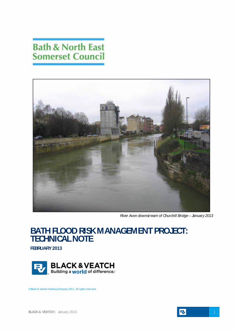
River Avon downstream of Churchill Bridge – January 2013
BATH FLOOD RISK MANAGEMENT PROJECT: TECHNICAL NOTE FEBRUARY 2013
©Black & Veatch Holding Company 2011. All rights reserved.

B&NES| BATH FLOOD RISK MANAGEMENT PROJECT: TECHNICAL NOTE
BLACK & VEATCH | January 2013 1
Table of Contents
1 Introduction ......................................................................................................................................................... 1 2 Scheme Requirements ...................................................................................................................................... 1 3 Scheme Proposals ............................................................................................................................................... 3 4 Next Steps ........................................................................................................................................................... 16
Appendices
Appendix A: Plan of Proposed Development Sites
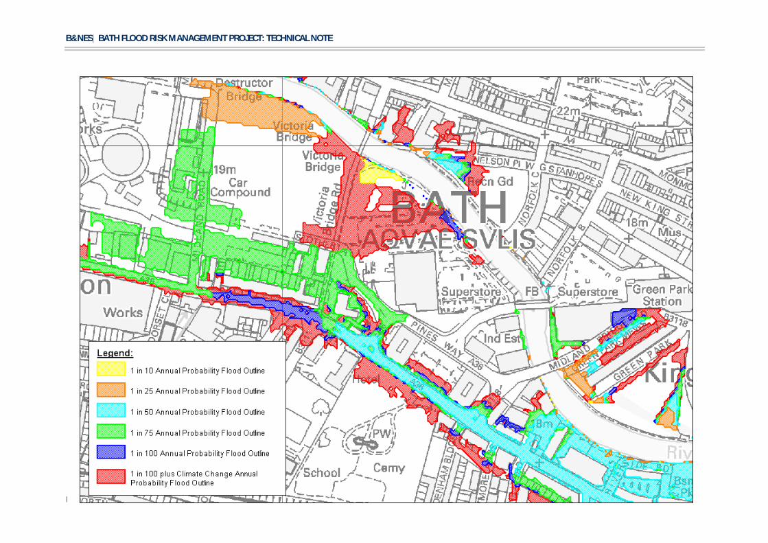
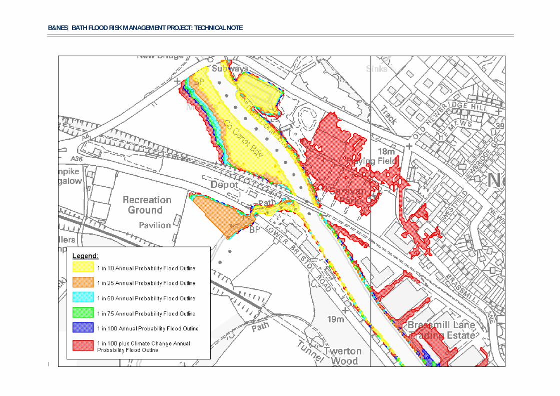
Appendix B: Flood Maps
Appendix C: Hydraulic Modelling
Appendix D: Plan of Proposed Improvements
Document Control
VERSION NO. PREPARED BY REVIEWED BY AUTHORISED FOR ISSUE
ISSUE DATE ISSUE STATUS
A.0 A Wallis / R Jones C Bown C Bown 16/01/13 DRAFT
B.0 A Wallis / R Jones C Bown C Bown 05/02/13 FINAL
Notice:
This report was prepared by Black & Veatch Limited (BVL) solely for use by Bath & North East Somerset Council (B&NES). This report is not addressed to and may not be relied upon by any person or entity other than B&NES for any purpose without the prior written permission of BVL. BVL, its directors, employees and affiliated companies accept no responsibility or liability for reliance upon or use of this report (whether or not permitted) other than by B&NES for the purposes for which it was originally commissioned and prepared.
In producing this report, BVL has relied upon information provided by others. The completeness or accuracy of this information is not guaranteed by BVL

B&NES| BATH FLOOD RISK MANAGEMENT PROJECT: TECHNICAL NOTE
BLACK & VEATCH | January 2013 1
1 Introduction
As part of the proposed Local Development Framework submission for the Bath and North East Somerset area, several new developments are proposed along the corridor of the River Avon in Bath. The proposed development sites are shown in Appendix A.
In order for the developments to satisfy the requirements of the National Planning Policy Framework (NPPF), they must not have an adverse impact on flood risk to third parties and must have a means of safe access/egress during flood conditions. It is proposed to, where necessary, raise all the development sites so that minimum floor levels are above the 1 in 100 (1%) annual probability flood event (with an additional allowance of 20% on peak flows for potential impacts of climate change or other uncertainties). Where possible the access/egress routes will also be raised above this level. However in certain locations this will be achieved through raising flood defence walls between the access routes and the river.
Black & Veatch Ltd (B&V) has been appointed by B&NES to consider flood mitigation measures that will be required to achieve these objectives, and to identify a scheme that will successfully mitigate any resulting increase in flood risk as a result of excluding flood water from parts of the floodplain. This technical note sets out the findings of B&V’s work, presents proposals for mitigating flood risk, and summarises the further work required to implement the solution.
2 Scheme Requirements
2.1 Flood risk The 1960s Bath Flood Defence Scheme was designed to pass flood flows as efficiently as possible through the city. This was achieved by providing a large capacity ‘canalised’ channel, which effectively acts as a flume to convey a significant volume of flow. When the Avon exceeds its bank-full capacity, water will flow onto its floodplain and return to the river where topography and river levels allow. Ground raising within developments would reduce the extent to which water could flow along the floodplain to add to the total volume conveyed through Bath during extreme floods.
There are some small areas where flood storage volume would be lost. However, the volume lost is negligible compared to the volume of water passing down the river when in flood (up to 400m3 or 400 tonnes every second). This is demonstrated by the fact that the computer model of the river and floodplain shows no increase in downstream flood levels if water is excluded completely from development sites by ground raising.
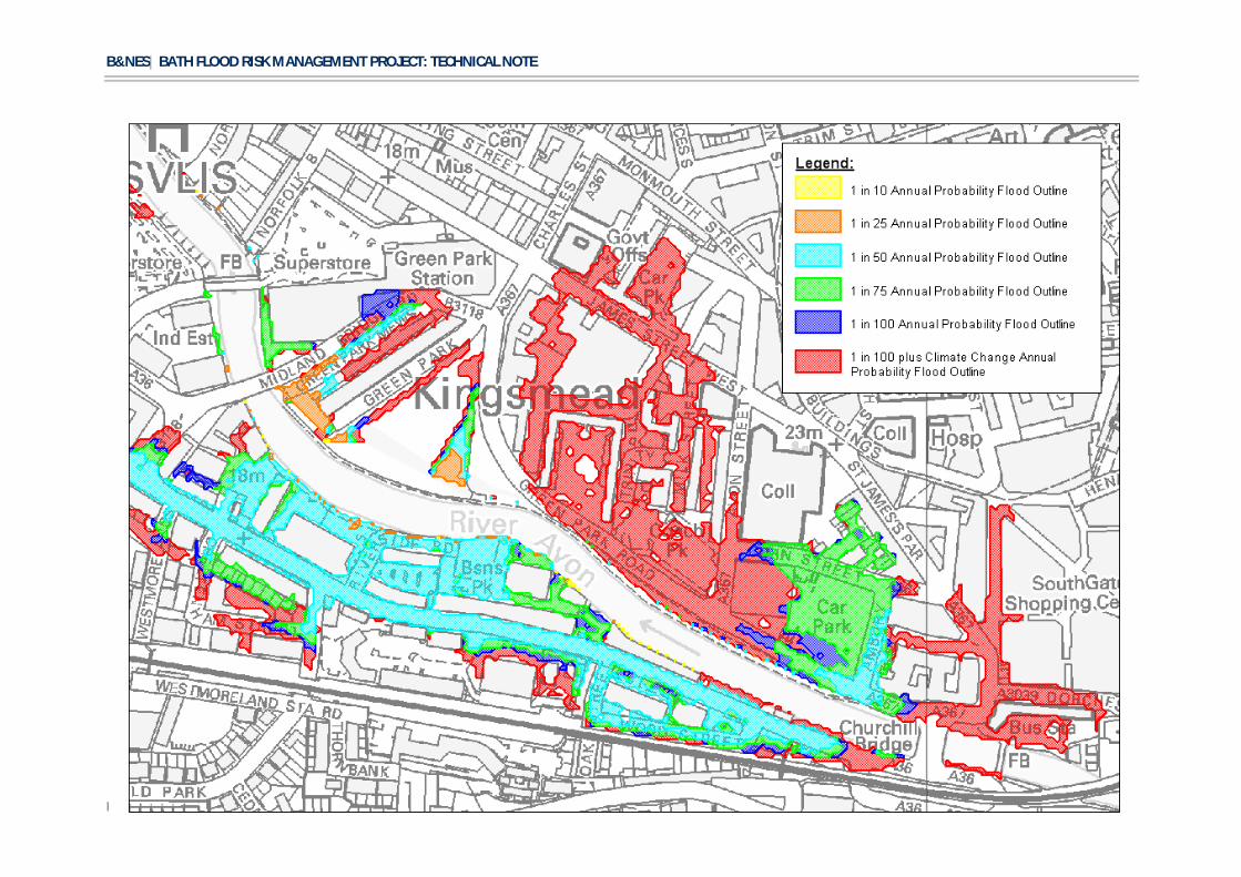
With all the development sites raised (but no mitigation) there is a maximum increase in level of 20mm in the 1 in 25 event, 30mm in the 1 in 50, 60mm in the 1 in 100 and 200mm in the 1 in 100 +20% event. (all probabilities refer to annual probability of exceedance of floods of that magnitude). These increases are to upstream levels as a result of the loss of flood conveyance capacity. This is a reflection of the fact that none of the development sites currently flood until a relatively large flood event. However by the 1 in 100 +20% event, large areas of the development sites are flooded. Appendix B shows the current flood extents under a range of annual probability events.
2.1.1 Channel Capacity As part of the design of the Bath Flood Defence Scheme in the 1960s the intention was that the channel would be ‘self cleansing’. This means that any silt that settled within the channel would be remobilised naturally by higher flows. Within the reach of the channel being considered as part of this study, this seems to have been largely successful. The Environment Agency has had a programme of surveying the bed levels

B&NES| BATH FLOOD RISK MANAGEMENT PROJECT: TECHNICAL NOTE
BLACK & VEATCH | January 2013 2
of the channel in this area and has seen little change over many years, suggesting that there has been no significant change at all in the standard of protection delivered by the original scheme. An extensive exercise was completed by the Environment Agency in 2012 in which the cross sectional areas were compared against survey data from 1985. This showed that in general the cross sectional areas were actually larger in 2012 than 1985.
It is apparent that, whilst in areas there does appear to have been an accumulation of silt, this will not have increased the flood risk as either it would be remobilised in a flood event or is areas where there is little flow (e.g. Pulteney Boat Dock).
2.1.2 Compensatory storage Options to provide compensatory flood storage upstream of Bath have been considered by B&NES as a means of mitigating the increase in flood risk. Previous studies, whilst suggesting upstream storage may be suitable, have all concluded that further more detailed computer modelling should be undertaken to confirm this approach.
This modelling has now been undertaken and confirms that, as stated above, the principal impact of raising developments is a loss of flow conveyance, rather than a loss of flood storage. To provide flood storage that would actually reduce peak flows in Bath would require a volume that is in excess of 10 million cubic metres and would need to be on land that currently does not flood. No suitable sites of this size are available upstream and therefore upstream storage is no longer being considered as part of any flood mitigation measures for these development sites.
There may be other development sites that come forward in the future which may result in a noticeable effect from loss of flood storage if they were raised above flood level. In previous studies, Batheaston Meadows upstream of Bath has been identified as the most suitable location to provide strategic flood storage mitigation. This is due to the availability of some land above flood levels, its proximity to Bath and the fact that it is owned by B&NES. Whilst this land is not required as part of this phase of works it would seem sensible to safeguard this land to allow it to be used in the future if required.
The move from the consideration of upstream flood storage to reduce flood risks towards a solution using compensatory flow conveyance (described below) is in part due to a number of local, national and international directives and strategies. These include the B&NES Public Realm and River Corridor strategies as well as the EU Water Framework Directive. These promote greater use of the river corridor for amenity and biodiversity purposes and encourage greater connection between the river and its floodplain.
2.1.3 Compensatory flow conveyance B&V has investigated whether the provision of compensatory flow conveyance along the river corridor is a viable means of mitigating flood risk. This option was investigated by adapting the existing computational hydraulic model of the River Avon, which was originally developed for the Environment Agency. The model comprises a 1-dimensional (ISIS Flow) representation of the river channel and structures, and a 2-dimensional (Tuflow) representation of the floodplain. The new developments were represented by raising ground levels within the 2-dimensional component. Model runs were undertaken to estimate the impact of this floodplain loss on river levels during extreme flood conditions. A full description of the hydraulic modelling is included in Appendix C.
The model was then modified to test options for providing additional flow conveyance at strategic locations where it is hydraulically feasible to modify the existing river banks. This was achieved by locally widening river cross sections to provide the additional conveyance.
B&NES| BATH FLOOD RISK MANAGEMENT PROJECT: TECHNICAL NOTE
BLACK & VEATCH | January 2013 3
The modelling concluded that the provision of compensatory flow conveyance at several locations would mitigate the increase in flood risk as a result of the loss of floodplain conveyance by excluding floodplain flow from the development sites in extreme flood events. For conveyance improvements to be successful they must take account of the following constraints:
· The level above which any conveyance improvements are provided is important. If the conveyance is provided at too low a level, flow in the Avon will slow down, causing river levels to rise locally. If the level is too high, conveyance will not be provided when required.
· The width of conveyance improvements is also important. Providing too wide a section will slow the flow down, causing an increase in levels. If insufficient width is provided, it will not be possible to completely mitigate the increase in flood risk.
· The conveyance improvements should be hydraulically continuous. Interruptions along the length of improvements, e.g. retaining existing bank profiles where mature trees are present, will not have the required effect. However, small items within the conveyance improvements, such as seating benches and lamp posts, would be acceptable.
· To fully mitigate the impact on flood risk, it will be necessary to complete the improvements in a phased manner depending on which development sites proceed first.
2.2 Safe access / egress Lower Bristol Road will form the main access to several of the proposed developments, which will be raised above the floodplain. NPPF requires that safe access to and from the development is maintained in all floods up to the future 1 in 100 year event.
B&V’s modelling has confirmed that the existing flood defences protecting Lower Bristol Road would be overtopped during a 1 in 50 annual probability event. The existing surface water drainage network in Lower Bristol Road has a limited capacity when discharge to the Avon is prevented by high river levels. Lower Bristol Road is therefore at risk of flooding from both the Avon and surface water. If not addressed, there would be no safe access to / egress from the development sites when the Avon is in flood.
In order to maintain safe access along Lower Bristol Road, the scheme must take account of the following:
· Overtopping of the existing defences must be avoided in the 1 in 100 +20% event. The conveyance improvements alone will not achieve this objective. B&V has estimated that the existing flood defences would need to be approximately 300 to 500mm higher than their current levels. This includes an allowance of 150m for freeboard.
· The scheme must include a means of reducing surface water flooding. This could be achieved through increasing the storage capacity of the drainage system. However, this is likely to be prohibitively expensive. Therefore it will be necessary to provide a pump station to mitigate surface water flooding during periods of high river flow.
3 Scheme Proposals The outline proposed improvements are described in this section. Plans showing the locations of the improvements are provided in Appendix D. B&V has referred to the following information in developing these proposals:
· Recollections of the 1960s Bath Flood Defence Scheme by Trevor Holroyd, who was involved in the development of that scheme. These recollections were assembled by B&V and provided to the Environment Agency in 2005 and form a useful reference.
· Utility service information provided by B&NES, including surface water drainage networks.
B&NES| BATH FLOOD RISK MANAGEMENT PROJECT: TECHNICAL NOTE
BLACK & VEATCH | January 2013 4
· Environmental information provided by B&NES.
· Online resources such as the Environment Agency website, the MAGIC website, the B&NES Adopted Local Plan, previous Environmental Statement for the Bath Riverside Development and the South Quays site.
· Topographical survey of the river banks undertaken by MK Surveys and procured by B&NES.
· 1960s scheme drawings provided by the Environment Agency.
3.1 Locations and description of improvements
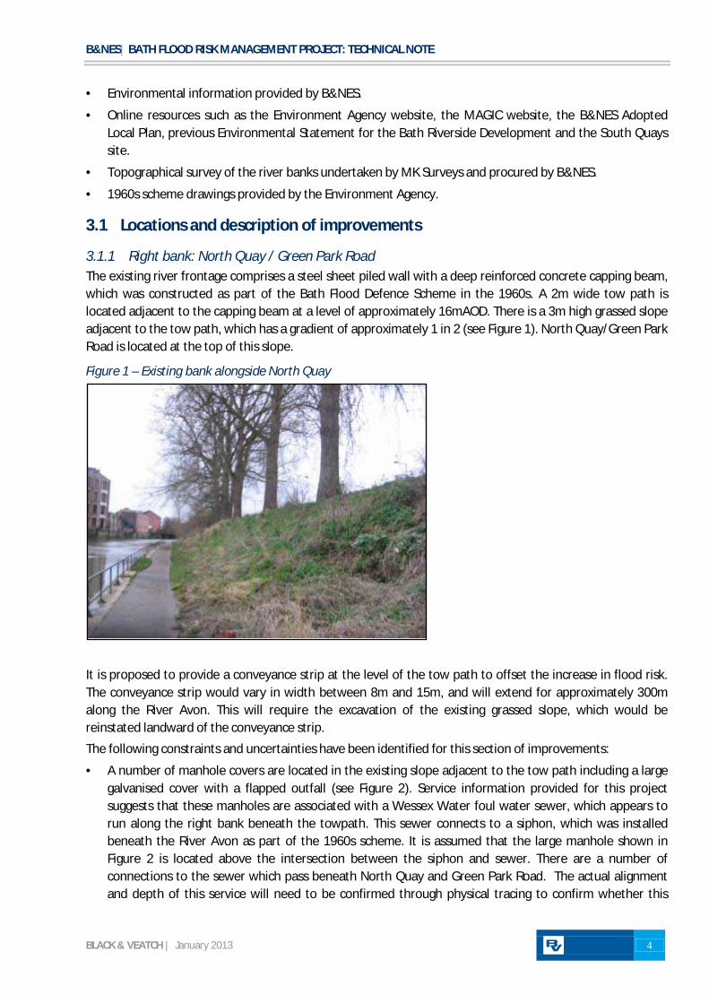
3.1.1 Right bank: North Quay / Green Park Road The existing river frontage comprises a steel sheet piled wall with a deep reinforced concrete capping beam, which was constructed as part of the Bath Flood Defence Scheme in the 1960s. A 2m wide tow path is located adjacent to the capping beam at a level of approximately 16mAOD. There is a 3m high grassed slope adjacent to the tow path, which has a gradient of approximately 1 in 2 (see Figure 1). North Quay/Green Park Road is located at the top of this slope.
Figure 1 – Existing bank alongside North Quay
It is proposed to provide a conveyance strip at the level of the tow path to offset the increase in flood risk. The conveyance strip would vary in width between 8m and 15m, and will extend for approximately 300m along the River Avon. This will require the excavation of the existing grassed slope, which would be reinstated landward of the conveyance strip.
The following constraints and uncertainties have been identified for this section of improvements:
· A number of manhole covers are located in the existing slope adjacent to the tow path including a large galvanised cover with a flapped outfall (see Figure 2). Service information provided for this project suggests that these manholes are associated with a Wessex Water foul water sewer, which appears to run along the right bank beneath the towpath. This sewer connects to a siphon, which was installed beneath the River Avon as part of the 1960s scheme. It is assumed that the large manhole shown in Figure 2 is located above the intersection between the siphon and sewer. There are a number of connections to the sewer which pass beneath North Quay and Green Park Road. The actual alignment and depth of this service will need to be confirmed through physical tracing to confirm whether this

B&NES| BATH FLOOD RISK MANAGEMENT PROJECT: TECHNICAL NOTE
BLACK & VEATCH | January 2013 5
service will need to be diverted to accommodate the proposed conveyance strip. However, in any case it will be necessary to modify manholes located in the existing slope, which will be lowered.
· A medium pressure gas main crosses from the south side to the north side of North Quay/Green Park Road at the upstream end of the proposed conveyance strip. The actual alignment and depth of this service will need to be confirmed through physical tracing. However, it would appear it is a safe distance from the excavations required for the conveyance strip. This utility (along with other utilities within the road) will be diverted as part of any realignment of this road.
· There are approximately 20 mature trees located along the top of the grassed slope. These would need to be removed to accommodate the conveyance strip. Notification to remove these trees will need to be submitted to the Local Planning Authority as the trees are within a Conservation Area. It is assumed that a substantial replanting scheme would be required to mitigate for the loss of mature trees. This will be agreed as part of a landscape mitigation scheme in consultation with the relevant B&NES officers.
· The conveyance strip will be approximately 300m long, and will be located within the functional floodplain of the Avon. It is recommended that pedestrian access ramps should be provided on the grassed slope to provide safe egress during flood conditions. These access ramps will need to be compliant with the requirements of the Disability Discrimination Act 2005.
· The composition of the existing slope is unknown. It is possible that the excavated material may be suitable for use in developing the Avon Street Car Park site. This will need to be confirmed prior to construction.
· It may be necessary for the improvements to encroach onto the existing North Quay/Green Park road, which is likely to contain a number of buried services. The function, alignment, depth and size of these services have not been confirmed. It is understood that this section of road will be removed as part of the development, and it is assumed that these services could therefore be isolated and diverted as part of the development. Encroachment into the road could be avoided by steepening the scope adjacent to the conveyance strip, or by providing retaining structures. However, safe access for maintenance of this slope will need to be considered.
Figure 2 – Large service cover and flapped outfall located opposite Camden Mill

B&NES| BATH FLOOD RISK MANAGEMENT PROJECT: TECHNICAL NOTE
BLACK & VEATCH | January 2013 6
3.1.2 Right Bank: Green Park Downstream of the proposed conveyance improvements described above, the tow path level rises by approximately 2m into Green Park. It is understood that the park was used as a deposit for construction spoil from the 1960s scheme. This was landscaped to create a raised ‘mound’ in the centre of the park (see Figure 3).
It is proposed to locally excavate into this raised ground to introduce a flood conveyance strip at a level of approximately 18mAOD. This will not require any modification of the exiting river bank.
The following constraints and uncertainties have been identified for this section of improvements:
· There are a number of mature trees that would need to be removed to accommodate the conveyance strip. Notification to remove these trees will need to be submitted to the Local Planning Authority as the trees are within a Conservation Area. Compensatory planting may be required to mitigate for the loss of these trees.
· The composition of material to be excavated is unknown. It is likely that this will be comprised of construction waste and/or arisings from the 1960s scheme and therefore could be contaminated.
· The foul sewer discussed in section 3.1.1 runs through the southern extent of Green Park. The actual alignment and depth of this service will need to be confirmed through physical tracing. However, since there will be no excavation below the lower ground level in Green Park (as can be seen in Figure 3), the risk of striking this service when constructing the conveyance strip is considered to be low.
Figure 3 –Green Park (raised ground to left of picture)
3.1.3 Left bank: Churchill Bridge to South Quays site It is understood that the existing river frontage downstream of Churchill Bridge was not intended to be improved during the 1960s scheme. However, the channel was dredged as part of that scheme, and this dredging is understood to have led to the partial collapse of the river wall downstream of Churchill Bridge. This was replaced with a full height reconstituted stone faced reinforced concrete wall. The transition between the vintages of river wall can be seen on site (see Figure 4). All other river walls along this section pre-date the 1960s scheme and the construction and condition are unknown.
The existing flood defence to Lower Bristol Road is provided by high ground levels (the road), flood defence walls, and buildings that are integral to the river frontage. The proposed improvements are described below for discrete sections of this defence. These improvements are required to reduce the flood risk to Lower

B&NES| BATH FLOOD RISK MANAGEMENT PROJECT: TECHNICAL NOTE
BLACK & VEATCH | January 2013 7
Bristol Road. The development sites along Lower Bristol Road themselves will be raised above flood levels. However their main access will be along Lower Bristol Road and to ensure this access is safe in times of flood the flood risk to the road needs to be reduced. These improvements will also provide a benefit to existing properties as well as traffic disruption.
Figure 4 – Transition of river wall construction downstream of Churchill Bridge
Churchill Bridges to Waterfront House
The floodwall section upstream of Waterfront House is approximately 1.5m high and appears to comprise a concrete stem with Bath stone facing. Stone capping is present along part of the wall. The flood wall appears to be founded directly on the river wall capping beam. The presence of reinforcement within the wall is unknown. This flood wall is connected to high ground (road level) by a masonry wall (see Figure 5).
Figure 5 – Flood wall upstream of Waterfront House
Section of wall understood to have been rebuilt in 1960s
Interface between old wall and 1960s wall

B&NES| BATH FLOOD RISK MANAGEMENT PROJECT: TECHNICAL NOTE
BLACK & VEATCH | January 2013 8
Apart from a 20m length immediately downstream of Churchill Bridges, the defences along this section would need to be raised by up to 0.5m to protect Lower Bristol Road up to the future 1 in 100 event. Raising of the existing defences would create a 2m high wall stem. Given the uncertainties about the construction of the flood wall, there are concerns about whether the raised wall would be capable of withstanding the additional hydrostatic loading imposed during a flood. Structural coring of the wall would help to confirm whether it would be viable to raise this wall. However, at this stage it is reasonable to assume that the flood wall should be replaced with a new, reinforced concrete wall and foundation. This could be accommodated within the 3m strip between the river wall and Lower Bristol Road. The wall would likely need to be faced and capped with stone to satisfy aesthetic planning requirements as the site is within a Conservation Area.
In addition to defence improvements along this section, it will be necessary to provide flaps to two large existing outfalls along this length (see Figure 6). These outfalls are believed to be Wessex Water owned, discharging surface water collected from higher ground to the south of the river. If these outfalls remained un-flapped, surcharging of the sewerage system could be possible when flows in the river are high.
The following constraints and uncertainties have been identified for this section of improvements:
· The proposed flood wall would be constructed on private land.
· No ground information is currently available for the design of the new flood wall. It is assumed that the material behind the existing river wall comprises unsuitable made ground, and that this would need to be replaced with a suitable material.
· There do not appear to be any buried services in proximity to the wall, with the exception of a low voltage electricity cable running along the kerbside of Lower Bristol Road. The alignment and depth of services would need to be confirmed through physical tracing prior to construction.
Figure 6 – Large outfall within river wall
Waterfront House
Waterfront House comprises two buildings. The more recent upstream building includes 5 windows, and the adjacent building 4 windows and a door, which face the river at or below ground floor level. The sills of these openings are located below the required defence level (see Figure 7), and therefore represent potential routes for flood water through to Lower Bristol Road. Some of these windows (if not all) currently have the ability to have flood boards placed over them in times of floods. Whilst the scheme will not increase the flood risk to these buildings, it may be necessary to increase the flood-proofing to these windows to preserve the integrity of the defences to Lower Bristol Road. This could be achieved by installing appropriate

B&NES| BATH FLOOD RISK MANAGEMENT PROJECT: TECHNICAL NOTE
BLACK & VEATCH | January 2013 9
glass systems or by providing improved temporary flood boards (if these can be installed by the owner safely when required).
There are a number of small outfalls through the Waterfront House frontage. These outfalls have flaps which appear to be in good condition.
Figure 7 – Windows facing river at Waterfront House
The following constraints and uncertainties have been identified for this section of improvements:
· Waterfront House is situated directly above the river wall, the age and condition of which is unknown. The integrity of the flood defences relies on the integrity of this river wall. It appears that improvements were made to the river wall along the newer part of Waterfront House, and information on this may be available.
· Waterfront House is a Grade II Listed Building therefore any works will required Listed Building Consent.
· The construction of the buildings and their foundations is not currently known. By preventing flow through the buildings, there would be a difference in water level across the walls of approximately 1.5m. The ability of the walls to withstand this hydrostatic loading will need to be confirmed by a structural engineer with relevant experience of historic buildings. This is of critical importance to ensure the safety of residents/employees within the buildings. If the walls are assessed as not being suitable, it may be possible to reinforce them on the internal face.
· The improvements to Waterfront House are likely to be disruptive. It is recommended that B&NES engages with the owner(s) of the buildings early to ensure a mutually acceptable solution is identified efficiently. The improvements will provide a benefit to the owner(s) as they will reduce the risk of internal flooding. However, since the driver for improvements is to facilitate development, there may be some reluctance by the owners to pay for these improvements.
Waterfront House to Camden Mill
The flood defence between the Waterfront House and Camden Mill buildings comprises a 1.2m high masonry wall directly over a masonry river wall (see Figure 8). From the riverward side, the flood wall appears to be of the same vintage as that upstream of Waterfront House. However, the wall section here is thicker. The internal construction of the wall is unknown.
To provide the requisite defence level, the wall would need to be raised by approximately 0.5m. As with the wall upstream of Waterfront House, there are concerns about whether the raised wall would be capable of withstanding the additional hydrostatic loading imposed. At this stage it is reasonable to assume that the

B&NES| BATH FLOOD RISK MANAGEMENT PROJECT: TECHNICAL NOTE
BLACK & VEATCH | January 2013 10
flood wall should be replaced with a new, reinforced concrete wall and foundation. This could be accommodated within the car park between the buildings. The wall would likely need to be faced and capped with stone to satisfy aesthetic planning requirements.
Figure 8 – Flood defence wall between Waterfront House and Camden Mill
The lowest point of Lower Bristol Road is located landward of this section. There is a manhole within the car park between the two buildings (can be seen in Figure 8), which appears to connect to a small un-flapped outfall in the river wall. It is assumed that this is part of the surface water drainage system in this location, which becomes overwhelmed during sustained periods of high flow in the Avon. To mitigate flooding of Lower Bristol Road from surface water, a pumping station would be required to discharge surface water when the existing network is surcharged. The South Quays development is approximately 150m west of the lowest point on Lower Bristol Road, although the lowest point in the drainage network may be in a different location. To minimise any drainage works within the road it would be preferable to locate the pump sump at this lowest point. However in terms of land ownership it would be preferable to locate this within the South Quays development site. The decision on any final location will need to consider the landownership costs against the costs and disruption from doing additional works within the road, and also between the pump and any outfall. The pump would need to have quite a large capacity in the order of 1m3/s. This will be confirmed as part of any detailed design phase based on the contributing drainage network and time that the river levels will be too high for gravity drainage.
The following constraints and uncertainties have been identified for this section of improvements:
· The proposed flood wall would be constructed on private land.
· No ground information is currently available for the design of the new flood wall. It is assumed that the material behind the existing river wall comprises unsuitable made ground, and that this would need to be replaced with a suitable material.
· There are a number of buried services within the car park, including a high voltage cable feeding the electricity substation near Camden Mill. The actual alignment and depth of these services will need to be confirmed through physical tracing. During further design work the difficulties of working in close proximity to these services will be fully addressed.
· There is limited working area near the entrance to the Camden Mill building (see Figure 8). The detailing of the new flood wall would need to take this into account.

B&NES| BATH FLOOD RISK MANAGEMENT PROJECT: TECHNICAL NOTE
BLACK & VEATCH | January 2013 11
· The possibility of contaminated land within the grounds of the petrol station would need to be determined to confirm whether this is an acceptable location for a pump station.
Camden Mill and Bayer Building
As with Waterfront House, both Camden Mill and the Bayer Building include a number of windows and doors facing the river, the sills of which are located below the required flood defence level (see Figure 9).
Figure 9 – Windows facing the river at Camden Mill and Bayer Building
These openings represent potential routes for flood water through to Lower Bristol Road. It will therefore be necessary to flood-proof these windows to preserve the integrity of the defences to Lower Bristol Road. This could be achieved by installing appropriate glass systems or by providing temporary flood boards (if these can be installed by the owner safely when required). It is believed that there is some degree of existing flood proofing within Camden Mill at least. That will be determined as part of the future work.
The following constraints and uncertainties have been identified for this section of improvements:
· Camden Mill is a Grade II Listed Structure; therefore any works will require Listed Building Consent.
· The buildings are situated directly above the river wall, the age and condition of which is unknown. The integrity of the flood defences relies on the integrity of this river wall.
· The construction of the buildings and their foundations is not currently known. By preventing flow through the buildings, there would be a difference in water level across the walls of approximately 1.5m. The ability of the walls to withstand this hydrostatic loading will need to be confirmed by a structural engineer with relevant experience of historic buildings. This is of critical importance to ensure the safety of residents/employees within the buildings. If the walls are assessed as not being suitable, it may be possible to reinforce them on the internal face.
· The improvements to Camden Mill and Bayer Building are likely to be disruptive. It is recommended that B&NES engages with the owner(s) of the buildings early to ensure a mutually acceptable solution is identified efficiently. The improvements will provide a benefit to the owner(s) as they will reduce the risk of internal flooding. However, since the driver for improvements is to facilitate development, there may be some reluctance by the owners to pay for these improvements.

B&NES| BATH FLOOD RISK MANAGEMENT PROJECT: TECHNICAL NOTE
BLACK & VEATCH | January 2013 12
3.1.4 Left bank: South Quays The existing river frontage along the South Quays development site comprises a mixture of different wall constructions, including timber piled walls, masonry walls, and natural bank. It is understood that this section of river frontage was not improved as part of the 1960s scheme, meaning that the walls are in excess of 50 years old. Parts of this frontage are in poor condition, particularly the section downstream of the masonry arches adjacent to the Bayer Building, where there are a number of voids visible (see Figure 10).
Figure 10 – River frontage in poor condition at South Quays site
It is envisaged that the river frontage along South Quays would need to be replaced to facilitate construction of the development site. This presents opportunities to provide a more consistent profile bank and also a new conveyance strip, similar to that created at the new Bath Western Riverside development downstream. The conveyance strip would need to be approximately 4m wide at a level of around 18mAOD, approximately 2m below the proposed ground level in South Quays. However as with other parts of these proposals, this could be refined as part of any more detailed design for this site.
It is envisaged at this stage that the new river frontage would comprise a steel sheet pile wall, which may need to be anchored, with a concrete capping beam. To maximise the development footprint, it is likely that a vertical retaining wall would be required landward of the flood conveyance strip. Access to the conveyance strip would need to be provided at either end. Assuming this can be accommodated within the development, the provision of a conveyance strip within South Quays would be less complicated than providing one on the opposite bank, where there is limited space between the river and Green Park Road.
The following constraints and uncertainties have been identified for this section of improvements:
· The developer is likely to improve the river frontage in this location and the addition of flood conveyance improvements is not likely to add significantly to costs. However, the improvements would need to be considered alongside plans for the development to ensure that they can be accommodated.
· The ground conditions at the site have not been confirmed, although much of this information should be available from previous studies.
· From previous studies it is known that there are high levels of some contaminants in this site and this will need to be considered when designing temporary works for installing a new river frontage.

B&NES| BATH FLOOD RISK MANAGEMENT PROJECT: TECHNICAL NOTE
BLACK & VEATCH | January 2013 13
3.1.5 Left bank: South Bank (Riverside Road) Between the South Quays development site and Midland Bridge Road there is another future development site bordered by the river and Lower Bristol Road. This is considered to be part of the Phase 2 development sites and will not be coming forward in the short term.
At present in extreme flood events there is the potential for flood water to cross this site and enter Lower Bristol Road. This water would then spread along a long length of the road. If this site comes forward for development then it will be necessary to raise ground levels to prevent this flow route. In the short term however it will be necessary to construct a flood wall along the length of this site. This would need to be 200m long and would vary in height between 1 to 1.5m. For the purposes of ensuring robust cost estimates, at this stage it is assumed that a flood wall would be required. However, other solutions such as demountable defences or temporary flood bunds will be considered during the next phase of the work in order to identify savings.
It is assumed that as the wall will not be able to be seen from the other bank and will form the rear boundary of a private site, so an aesthetic facing would not be required.
The following constraints and uncertainties have been identified for this section of improvements:
· The proposed flood wall would be constructed on private land.
· No ground information is currently available for the design of the new flood wall.
· There are some buried services within the site, mainly surface water sewers. The actual alignment and depth of these services will need to be confirmed through physical tracing.
· There are two buildings at the western end of this site adjacent to Midland Bridge Road. These are shown in the figure below. Depending on the current internal floor levels of these buildings they may need some element of flood proofing. This will be determined as part of the next phase of work.
Figure 11 – Buildings at end of South Bank site
3.1.6 Left bank: Bath Western Riverside The first phase of the Bath Western Riverside development included the provision of an 8m wide strip at a level of 16mAOD (see Figure 11). It is proposed to continue this strip throughout the remainder of the Bath Western Riverside development to Destructor Bridge, adopting the same detail. At present this is shown continuing the level of 16mAOD, however as this work progresses there will be further assessment on this to determine the optimum level of this walkway. This will be based on having a low enough level that it

B&NES| BATH FLOOD RISK MANAGEMENT PROJECT: TECHNICAL NOTE
BLACK & VEATCH | January 2013 14
provides the necessary flood conveyance benefits, whilst also being at a high enough level that flooding of the walkway does not occur too frequently.
Figure 12 – Existing conveyance at Bath Western Riverside
3.2 Environmental impacts Table 3.1 provides potential impacts of the proposals at each of the locations. A desk study of the proposals has been undertaken and has identified that generally:
· The whole of Bath has World Heritage Site status. This will not be affected by the proposals which will be sensitively designed to ensure that the character of the riverside is unchanged. A landscape assessment will be required of the proposals in full consultation with the B&NES Landscape Architect.
· During construction there could be negative impacts on the road network from construction traffic which will need to be planned carefully.
· The works to the right bank are within the Bath Conservation Area on the B&NES Adopted Local Plan 2007. Agreement with the B&NES Tree Officer on proposals to remove and replant trees will be required before notification of tree works is provided to them.
· The River Avon is a Site of Nature Conservation Interest (SNCI) and therefore the works must ensure that the river is protected. There are no statutory nature conservation sites within 2km of the proposals apart from Kensington Meadows Local Nature Reserve which is located approximately 1.8km north east and will not be affected.
· Bath has a rich history and therefore the potential for the recovery of buried archaeological deposits or finds is high with any ground breaking activity. Further desk based assessments and a programme of archaeological investigation will be required for any proposals.
· The waterbody classification of the stretch of the River Avon adjacent to the works under the Water Framework Directive is Good Ecological Potential. The proposals will need to be screened to ensure that improving the conveyance during flood events does not affect the ecological potential of the waterbody.

B&NES| BATH FLOOD RISK MANAGEMENT PROJECT: TECHNICAL NOTE
BLACK & VEATCH | January 2013 15
Table 3.1 - Specific Environmental Impacts and Proposed Mitigation of the Bath Flood Risk Management Project Location Key Environmental Impacts, Proposed Mitigation and Opportunities Right Bank: Broad Quay / Green Park Road
· Loss of approximately 20 trees, a tree planting scheme to mitigate for the loss of these trees will be required. · The river side path will be closed for the widening works. A diversion will be required to ensure that the cycle links
to National Cycle Network 4 are maintained. Widening the cycle path in this location will improve the accessibility of the path. Other enhancements could be incorporated to the design to improve the amenity of the area.
· The design should aim to reuse the material excavated from the slope of find a location where it can be recycled. The material will require testing to ensure that it is not contaminated.
Right Bank: Green Park
· Downstream is the Grade II Listed Victoria Bridge. The proposals will need to be landscaped to complement the bridge.
· There are opportunities to enhance the amenity of this area with street furniture and interpretation display materials.
· There will be disruption to the users of the park during the works. Advance notice, sensitive programming and phased working will mitigate this impact.
· Loss of approximately ten mature trees. A tree planting scheme will be required to mitigate for the loss of trees. Left Bank: Churchill Bridge to Waterfront House
· No specific impacts have been identified.
Left Bank: Waterfront House
· Users of the affected properties will be disturbed during flood events if they have to install temporary boards · However, improvements will reduce risk internal flooding of buildings. · Waterfront House is a Grade II Listed Building. Any works to the property will require Listed Building Consent.
Left Bank: Waterfront House to Camden Mill
· Temporary use of the car park to construct the wall. Alternative parking provision may need to be provided.
Left Bank: Camden Mill and Bayer Building
· Users of the affected properties will be disturbed during flood events if they have to install temporary boards. · However, improvements will reduce risk internal flooding of buildings. · Camden Mill is a Grade II Listed Building. Any works to the property will require Listed Building Consent.
Left Bank: South Quays
· The proposals and potential environmental impacts of measures to improve conveyance in this section will be detailed by the eventual developers of the site.
· A previous application for an educational centre in the development was not granted planning permission. An Environmental Statement was prepared in 2006 which noted that there may be potential impacts on environmental receptors such as archaeology, the Newarks Works, protected species, the River Avon SNCI amongst others.
· Any piling to create a new river frontage is likely to need to avoid the salmonids migration periods (15th October 15th April) and may require noise and vibration monitoring.

B&NES| BATH FLOOD RISK MANAGEMENT PROJECT: TECHNICAL NOTE
BLACK & VEATCH | January 2013 16
Location Key Environmental Impacts, Proposed Mitigation and Opportunities Left Bank: Bath Riverside Development
An Environmental Statement has been prepared for the development which identified the following, which will be relevant for extending the conveyance improvements downstream: · Impacts on air quality from dust and emissions will be mitigated by measures included in a Construction
Environmental Management Plan. · A Bronze Age sword was found on the former gas work site indicating evidence for prehistoric activity in the
area; there are also records from the 19th and 20th Century industrial development of the area and the Roman period. A programme of archaeological investigation will be undertaken.
· Slow worms have been recorded and the area has interest for invertebrates. There are sightings of otter; although habitats on site are unsuitable. Bat surveys showed no bat roosts. The developer proposed a number of mitigation measures and enhancements in the form of reed rafts in the River Avon.
· The previous industrial uses of the site have led to contamination. Further ground investigation would be undertaken to establish a remediation plan.
· The development would have effects on microclimate but these effects would be reduced once landscape planting had established.
· Noise impacts were considered negligible as the area is also part of a busy road network. · There would be social impacts from the additional accommodation but this is considered to be outweighed by
the social benefits from the development. · There will be improvements in the visual realm for near views of the site however, there would be a limited loss
of openness which interruption of certain views across the Avon Valley. This would be mitigated with good design.
4 Next Steps
4.1 Screening decision and planning It will be necessary to obtain a screening decision from B&NES planning officers to determine the consenting requirements for the flood mitigation improvements.
The proposals will require planning permission. The proposals are listed on Schedule 2 of the Town and Country Planning (Environmental Impact Assessment) (England and Wales) Regulations 1999 and are within a ‘sensitive site’ (i.e. World Heritage Site) as defined in the regulations however, the nature of the works may preclude the need for a statutory Environmental Impact Assessment (EIA). A comprehensive screening request will be submitted to the planning officers to determine this.
4.2 Design development To address the uncertainties presented in this technical note, it will be necessary to develop the design of the scheme prior to submission of a planning application and Flood Defence Consent application. This would involve the following work:
· Confirming the alignment, function, depth and size of services affected by the proposed improvements. This is likely to require physical service tracing and mapping.
· Undertaking ground investigations to inform the foundation design of new flood walls, bank stability, and the risk of ground contamination.
· Obtaining structural cores from the existing flood walls to confirm their construction, and to conclude whether they can be raised.
· Collaboration with B&NES landscape architects to undertake a Landscape Assessment to ensure the scheme achieves engineering objectives as well as the likely aesthetic requirements raised during the planning process.
· An Extended Phase 1 Habitat Survey to identify any ecological risks of the proposals and an Arboricultural Assessment of any trees to be lost.
· An Archaeological Desk Based Assessment and liaison with the County Archaeologist.

B&NES| BATH FLOOD RISK MANAGEMENT PROJECT: TECHNICAL NOTE
BLACK & VEATCH | January 2013 2
· Consultation with landowners.
· Consultation with statutory stakeholders to obtain their views on the proposals and to identify risks and mitigation. This will include the Environment Agency and the B&NES Planning Officer.

B&NES| BATH FLOOD RISK MANAGEMENT PROJECT: TECHNICAL NOTE
BLACK & VEATCH | January 2013
APPENDIX A
Plan of Proposed Development Sites

B&NES| BATH FLOOD RISK MANAGEMENT PROJECT: TECHNICAL NOTE
BLACK & VEATCH | January 2013

B&NES| BATH FLOOD RISK MANAGEMENT PROJECT: TECHNICAL NOTE
BLACK & VEATCH | January 2013
APPENDIX B
Flood Maps

B&NES| BATH FLOOD RISK MANAGEMENT PROJECT: TECHNICAL NOTE
BLACK & VEATCH | January 2013

B&NES| BATH FLOOD RISK MANAGEMENT PROJECT: TECHNICAL NOTE
BLACK & VEATCH | January 2013

B&NES| BATH FLOOD RISK MANAGEMENT PROJECT: TECHNICAL NOTE
BLACK & VEATCH | January 2013
B&NES| BATH FLOOD RISK MANAGEMENT PROJECT: TECHNICAL NOTE
BLACK & VEATCH | January 2013
B&NES| BATH FLOOD RISK MANAGEMENT PROJECT: TECHNICAL NOTE
BLACK & VEATCH | January 2013

B&NES| BATH FLOOD RISK MANAGEMENT PROJECT: TECHNICAL NOTE
BLACK & VEATCH | January 2013

B&NES| BATH FLOOD RISK MANAGEMENT PROJECT: TECHNICAL NOTE
BLACK & VEATCH | January 2013

B&NES| BATH FLOOD RISK MANAGEMENT PROJECT: TECHNICAL NOTE
BLACK & VEATCH | January 2013
B&NES| BATH FLOOD RISK MANAGEMENT PROJECT: TECHNICAL NOTE
BLACK & VEATCH | January 2013

B&NES| BATH FLOOD RISK MANAGEMENT PROJECT: TECHNICAL NOTE
BLACK & VEATCH | January 2013
APPENDIX C
Hydraulic Modelling

B&NES| BATH FLOOD RISK MANAGEMENT PROJECT: TECHNICAL NOTE
BLACK & VEATCH | January 2013
The ISIS-Tuflow model produced by Halcrow Ltd, as part of the Corston to Avonmouth Flood Zone Compliance Project, was provided by the Environment Agency (EA). Two separate models covered the River Avon from the A4 crossing at Bathford to New Bridge Park & Ride titled Bath_us_2005 and Bath_ds_2005. The downstream model (Bath_ds_2005) was of primary interest, covering the reach of the River Avon between Cleveland Bridge and New Bridge Park Ride. The 1D element of the model was based on the B&V ISIS model produced in 2004 as part of the Bath Flood Defence Study, whilst the 2D element of the model was constructed as part of the Corston to Avonmouth Flood Zone Compliance Project.
Background
The 2005 Halcrow model was reviewed during the early stages of this study. In general it was found to be suitable to use for this project. However the following improvements were made to it.
Updates to the Baseline Model
Representation of Bath Western Riverside
As no representation of the development had been made in the Halcrow model, the 1D and 2D elements of the downstream model were updated.
The walkways already constructed as part of the Western Riverside development were included within the ISIS model cross-sections on the left bank between model cross-sections RC035 and RC033, based on Grant Associates drawings: BWR197-AL-A01-GE-2-020, BWR197-AL-A01-GE-2-022 and BWR197-AL-A01-GE-2-024.
The landscaping proposed as part of the Bath Western Riverside Development was represented in the 2D domain through the use of z-shapes. As permission has been granted for the entire Bath Western Riverside development (including the mitigation works) it was decided that any baseline model should assume full development of this site. Proposed ground levels were taken from Section 3.5 of the Bath Western Riverside Landscape Brief and Masterplan Context for Proposed Replacement of the Destructor Bridge dated 11 July 2012. The final model configuration and ground levels applied in the 2D domain can be seen below in Figure 1.

B&NES| BATH FLOOD RISK MANAGEMENT PROJECT: TECHNICAL NOTE
BLACK & VEATCH | January 2013
Figure 1: Representation of Bath Western Riverside in the 2D domain
Representation of Buildings
Buildings were represented in the 2D domain by artificially increasing the elevation of z-points within the footprint of each building through the use of z-shapes. This prevented conveyance through buildings, creating a barrier to floodplain flows and can be considered a worst case scenario. An arbitrary elevation of 100mAOD was applied to each building which were defined using OS MasterMap data.
Alteration of the 1D-2D Boundary
Review of the Halcrow ISIS model indicated that the tow path on the right bank of the river between Churchill Bridge and Twerton Sluice had been removed, allowing representation of this area to be included in the 2D domain. As it was considered more accurate to represent this conveyance area in the 1D model, the 1D-2D model boundary was amended (2d_code and 2d-bc layers). This also allowed easier (and more accurate) representation of the mitigation options in this area.
1D Model Cross-Sections
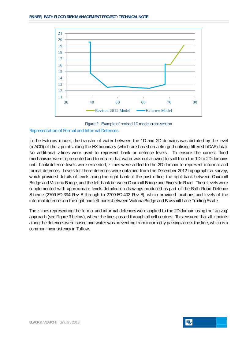
Based on the above change to the 1D-2D model boundary, 1D model cross-sections were reviewed between Henrietta Park and the Weston Cut (Canal) (RC058 to RC021). Where appropriate, cross-sections were amended to extend as far as adjacent buildings and walls and to include the tow path on the right bank. Original cross-section data was obtained from the B&V mode dated 2005 (which was based on topographic survey data). An example of an amended cross-section can be seen below in Figure 2.
B&NES| BATH FLOOD RISK MANAGEMENT PROJECT: TECHNICAL NOTE
BLACK & VEATCH | January 2013
Figure 2: Example of revised 1D model cross-section
Representation of Formal and Informal Defences
In the Halcrow model, the transfer of water between the 1D and 2D domains was dictated by the level (mAOD) of the z-points along the HX boundary (which are based on a 4m grid utilising filtered LiDAR data). No additional z-lines were used to represent bank or defence levels. To ensure the correct flood mechanisms were represented and to ensure that water was not allowed to spill from the 1D to 2D domains until bank/defence levels were exceeded, z-lines were added to the 2D domain to represent informal and formal defences. Levels for these defences were obtained from the December 2012 topographical survey, which provided details of levels along the right bank at the post office, the right bank between Churchill Bridge and Victoria Bridge, and the left bank between Churchill Bridge and Riverside Road. These levels were supplemented with approximate levels detailed on drawings produced as part of the Bath Flood Defence Scheme (2709-ED-394 Rev B through to 2709-ED-402 Rev B), which provided locations and levels of the informal defences on the right and left banks between Victoria Bridge and Brassmill Lane Trading Estate.
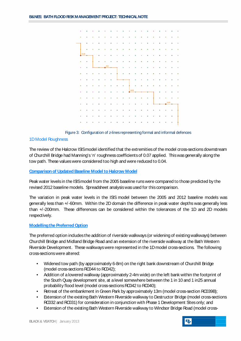
The z-lines representing the formal and informal defences were applied to the 2D domain using the ‘zig-zag’ approach (see Figure 3 below), where the lines passed through all cell centres. This ensured that all z-points along the defences were raised and water was preventing from incorrectly passing across the line, which is a common inconsistency in Tuflow.
11 12 13 14 15 16 17 18 19 20 21
30 40 50 60 70 80
Revised 2012 Model Halcrow Model
B&NES| BATH FLOOD RISK MANAGEMENT PROJECT: TECHNICAL NOTE
BLACK & VEATCH | January 2013
Figure 3: Configuration of z-lines representing formal and informal defences
1D Model Roughness
The review of the Halcrow ISIS model identified that the extremities of the model cross-sections downstream of Churchill Bridge had Manning’s ‘n’ roughness coefficients of 0.07 applied. This was generally along the tow path. These values were considered too high and were reduced to 0.04.
Peak water levels in the ISIS model from the 2005 baseline runs were compared to those predicted by the revised 2012 baseline models. Spreadsheet analysis was used for this comparison.
Comparison of Updated Baseline Model to Halcrow Model
The variation in peak water levels in the ISIS model between the 2005 and 2012 baseline models was generally less than +/-60mm. Within the 2D domain the difference in peak water depths was generally less than +/-200mm. These differences can be considered within the tolerances of the 1D and 2D models respectively.
The preferred option includes the addition of riverside walkways (or widening of existing walkways) between Churchill Bridge and Midland Bridge Road and an extension of the riverside walkway at the Bath Western Riverside Development. These walkways were represented in the 1D model cross-sections. The following cross-sections were altered:
Modelling the Preferred Option
· Widened tow path (by approximately 6-8m) on the right bank downstream of Churchill Bridge (model cross-sections RC044 to RC042);
· Addition of a lowered walkway (approximately 2-4m wide) on the left bank within the footprint of the South Quay development site, at a level somewhere between the 1 in 10 and 1 in25 annual probability flood level (model cross-sections RC042 to RC040);
· Retreat of the embankment in Green Park by approximately 13m (model cross-section RC039B); · Extension of the existing Bath Western Riverside walkway to Destructor Bridge (model cross-sections
RC032 and RC031) for consideration in conjunction with Phase 1 Development Sites only; and · Extension of the existing Bath Western Riverside walkway to Windsor Bridge Road (model cross-

B&NES| BATH FLOOD RISK MANAGEMENT PROJECT: TECHNICAL NOTE
BLACK & VEATCH | January 2013
sections RC032 to RC028) for consideration in conjunction with All Development Sites.
It is proposed to raise the walls along the left bank between Churchill Bridge and the South Quay Development Site as part of the preferred option. This would prevent flooding onto Lower Bristol Road, preventing property flooding and traffic disruption. The representation of this wall raising in the 2D domain can be seen in
Raising of walls downstream of Churchill Bridge
Figure 4 below.
Figure 4: Wall raising along Lower Bristol Road as part of the preferred option
As part of the preferred option, Green Park Road will be raised (or the land in this area following the diversion of Green Park Road as part of the development of the Avon Street Car Park site) between Churchill Bridge and Green Park to prevent flooding. This element of the option was represented in the 2D domain through the use of a z-shape. The elevation of the road raising will be refined during detailed design.
The development sites were represented in the 2D domain by artificially increasing the elevation of z-points within the footprint of each site through the use of z-shapes. This prevented conveyance through each site, creating a barrier to floodplain flows, and can be considered a worst case scenario. The extent of ground raising within each development site boundary was agreed with Bath & North East Somerset Council at a meeting held on Wednesday 24th October 2012. This ground raising within each site can be seen below.
B4 – Manvers Street 100% of site raised

B&NES| BATH FLOOD RISK MANAGEMENT PROJECT: TECHNICAL NOTE
BLACK & VEATCH | January 2013
B6 – Avon Street Car Park 100% raising of area not within riverside path widening
B7 – Green Park Assuming existing store footprint stays (already above flood levels). Car park to be raised.
B8 – BWR East Assumed 8m strip can be left alongside river. Remainder of site raised.
B9a – South Quays 100% of site raised

B&NES| BATH FLOOD RISK MANAGEMENT PROJECT: TECHNICAL NOTE
BLACK & VEATCH | January 2013
B13a – Stable Yard Assume Stable Yard itself remains as current. 8m strip left alongside river with remainder of site raised.
B9b – South Bank 100% of site raised
B13b – Lower Bristol Road Riverside strip left as existing, remainder of site raised
B13c – Cars Mill Phase 1 Riverside strip left as existing, remainder of site raised
B&NES| BATH FLOOD RISK MANAGEMENT PROJECT: TECHNICAL NOTE
BLACK & VEATCH | January 2013
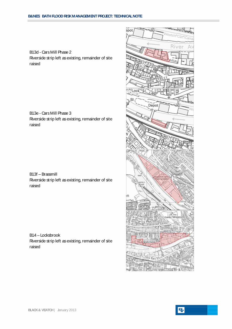
B13d - Cars Mill Phase 2 Riverside strip left as existing, remainder of site raised
B13e - Cars Mill Phase 3 Riverside strip left as existing, remainder of site raised
B13f – Brassmill Riverside strip left as existing, remainder of site raised
B14 – Locksbrook Riverside strip left as existing, remainder of site raised

B&NES| BATH FLOOD RISK MANAGEMENT PROJECT: TECHNICAL NOTE
BLACK & VEATCH | January 2013
B15 – The Maltings 100% of site raised
B18 – Westmark 100% of site raised
B19 – TA centre 100% of site raised
B20 – Onega Centre Assumed 8m riverside strip to be left, remainder of site raised

B&NES| BATH FLOOD RISK MANAGEMENT PROJECT: TECHNICAL NOTE
BLACK & VEATCH | January 2013
B21 – Hinton Garage Assumed riverside strip to be left, remainder of site raised
Two scenarios were modelled representing the preferred option. The first scenario considered the inclusion of Phase 1 Development Sites only (B4, B6, B7, B8 and B13a) and the second scenario considered the inclusion of All Development Sites.
Results of the Preferred Option
Table 1 to Table 3 below summarise the change in flood levels at selected key locations at different annual probability events.
Change in level from baseline (mm) Location Phase 1 Development Sites All Development Sites Pulteney Bridge -20 -30 St James Railway Bridge -30 -30 Churchill Bridge -30 -40 New Windsor Bridge 0 0 Twerton Sluices 0 0 New Bridge 0 0
Table 1: 1 in 50 Annual Probability Event
Change in level from baseline (mm) Location Phase 1 Development Sites All Development Sites Pulteney Bridge -80 -60 St James Railway Bridge -40 -40 Churchill Bridge -40 -40 New Windsor Bridge 0 +10 Twerton Sluices 0 +10 New Bridge 0 0
Table 2: 1 in 100 Annual Probability Event
Change in level from baseline (mm) Location Phase 1 Development Sites All Development Sites Pulteney Bridge +10 +20 St James Railway Bridge +10 0 Churchill Bridge 0 0 New Windsor Bridge +10 0 Twerton Sluices 0 +10 New Bridge 0 0
B&NES| BATH FLOOD RISK MANAGEMENT PROJECT: TECHNICAL NOTE
BLACK & VEATCH | January 2013
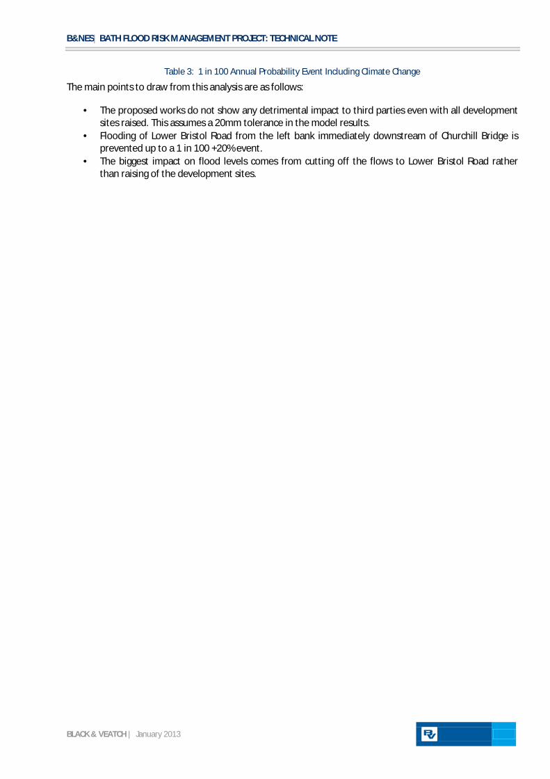
Table 3: 1 in 100 Annual Probability Event Including Climate Change
The main points to draw from this analysis are as follows:
· The proposed works do not show any detrimental impact to third parties even with all development sites raised. This assumes a 20mm tolerance in the model results.
· Flooding of Lower Bristol Road from the left bank immediately downstream of Churchill Bridge is prevented up to a 1 in 100 +20% event.
· The biggest impact on flood levels comes from cutting off the flows to Lower Bristol Road rather than raising of the development sites.
B&NES| BATH FLOOD RISK MANAGEMENT PROJECT: TECHNICAL NOTE
BLACK & VEATCH | January 2013
APPENDIX D
Plan of Scheme Proposals

B&NES| BATH FLOOD RISK MANAGEMENT PROJECT: TECHNICAL NOTE
BLACK & VEATCH | January 2013

B&NES| BATH FLOOD RISK MANAGEMENT PROJECT: TECHNICAL NOTE
BLACK & VEATCH | January 2013