Basis of Structural DesignSteel plate girder Steel plate girder: heavy flanges and thin web welded...
29
Basis of Structural Design Course 3 Structural action: trusses and beams Course notes are available for download at https://www.ct.upt.ro/studenti/cursuri/stratan/bsd.htm
Transcript of Basis of Structural DesignSteel plate girder Steel plate girder: heavy flanges and thin web welded...
Basis of Structural Design
Course 3
Structural action: trusses and beams
Course notes are available for download athttps://www.ct.upt.ro/studenti/cursuri/stratan/bsd.htm
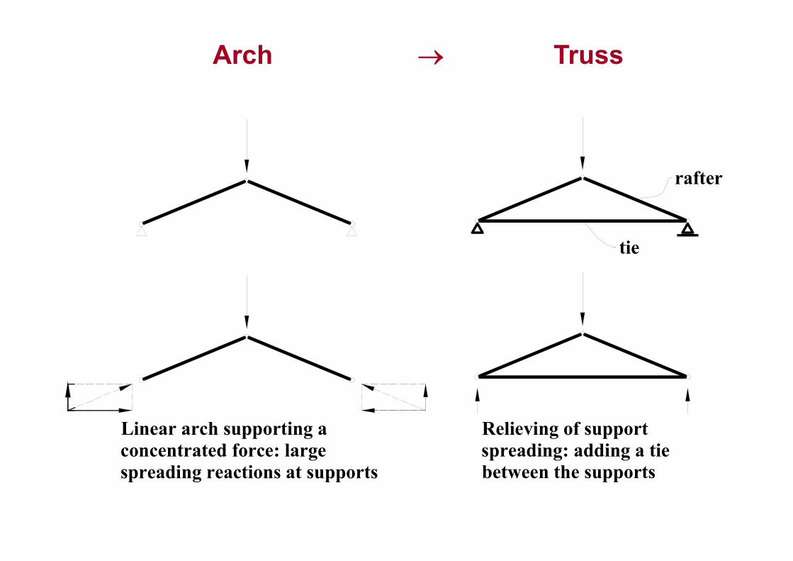
Arch
Linear arch supporting aconcentrated force: largespreading reactions at supports
rafter
tie
Relieving of supportspreading: adding a tiebetween the supports
Truss
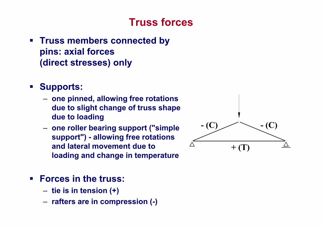
Truss forces
Truss members connected by pins: axial forces (direct stresses) only
Supports:– one pinned, allowing free rotations
due to slight change of truss shape due to loading
– one roller bearing support ("simple support") - allowing free rotations and lateral movement due to loading and change in temperature
Forces in the truss:– tie is in tension (+)
– rafters are in compression (-)
- (C) - (C)
+ (T)
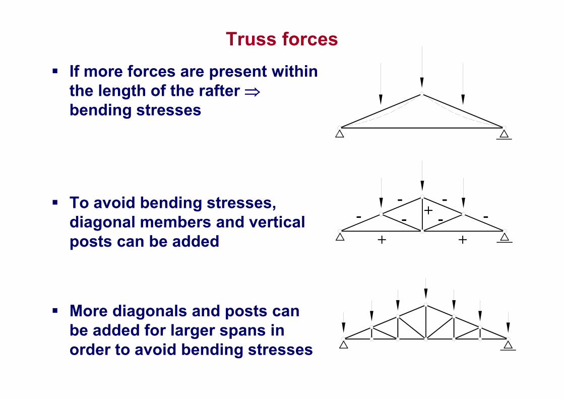
Truss forces
If more forces are present within the length of the rafter bending stresses
To avoid bending stresses, diagonal members and vertical posts can be added
More diagonals and posts can be added for larger spans in order to avoid bending stresses
-
+ +
-
---
-+
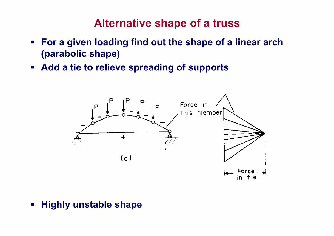
Alternative shape of a truss
For a given loading find out the shape of a linear arch (parabolic shape)
Add a tie to relieve spreading of supports
Highly unstable shape
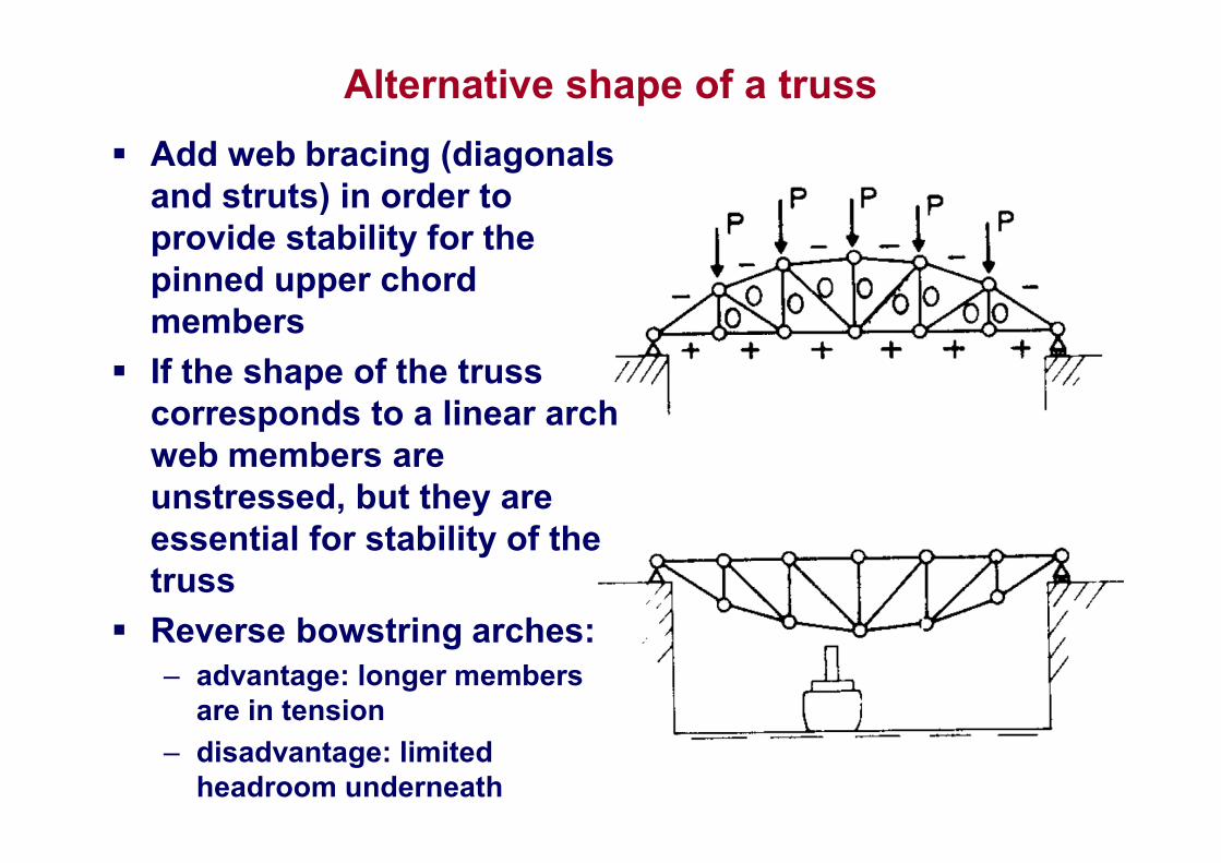
Alternative shape of a truss
Add web bracing (diagonals and struts) in order to provide stability for the pinned upper chord members
If the shape of the truss corresponds to a linear arch web members are unstressed, but they are essential for stability of the truss
Reverse bowstring arches:– advantage: longer members
are in tension
– disadvantage: limited headroom underneath
Truss shapes
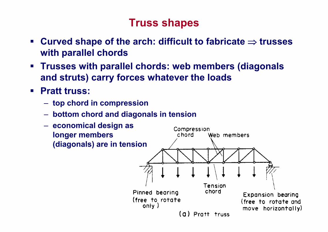
Curved shape of the arch: difficult to fabricate trusses with parallel chords
Trusses with parallel chords: web members (diagonals and struts) carry forces whatever the loads
Pratt truss:– top chord in compression
– bottom chord and diagonals in tension
– economical design as longer members (diagonals) are in tension
Truss shapes
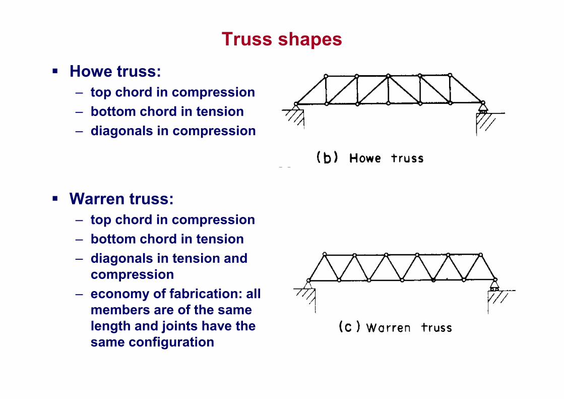
Howe truss:– top chord in compression
– bottom chord in tension
– diagonals in compression
Warren truss:– top chord in compression
– bottom chord in tension
– diagonals in tension and compression
– economy of fabrication: all members are of the same length and joints have the same configuration
Truss joints
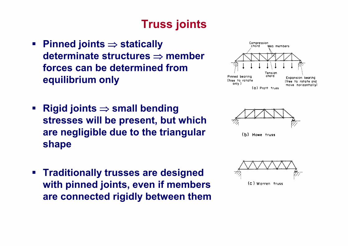
Pinned joints statically determinate structures member forces can be determined from equilibrium only
Rigid joints small bending stresses will be present, but which are negligible due to the triangular shape
Traditionally trusses are designed with pinned joints, even if members are connected rigidly between them
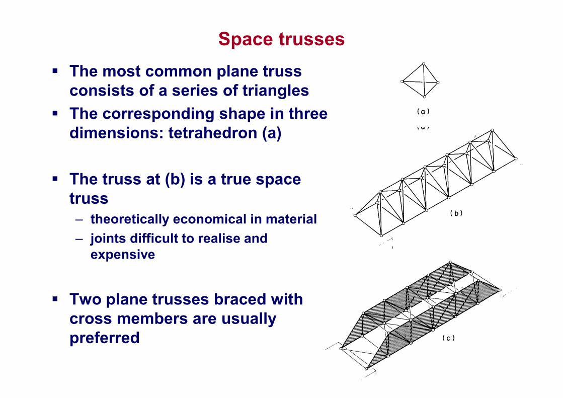
Space trusses
The most common plane truss consists of a series of triangles
The corresponding shape in three dimensions: tetrahedron (a)
The truss at (b) is a true space truss– theoretically economical in material
– joints difficult to realise and expensive
Two plane trusses braced with cross members are usually preferred
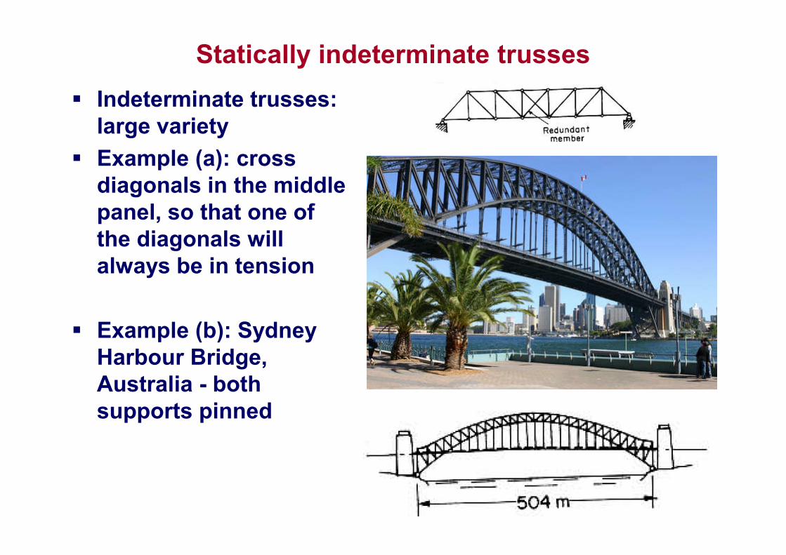
Statically indeterminate trusses
Indeterminate trusses: large variety
Example (a): cross diagonals in the middle panel, so that one of the diagonals will always be in tension
Example (b): Sydney Harbour Bridge, Australia - both supports pinned
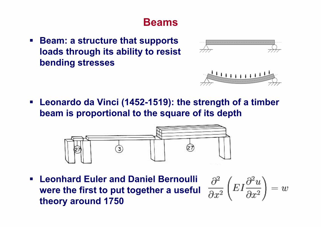
Beams
Beam: a structure that supports loads through its ability to resist bending stresses
Leonardo da Vinci (1452-1519): the strength of a timber beam is proportional to the square of its depth
Leonhard Euler and Daniel Bernoulli were the first to put together a useful theory around 1750
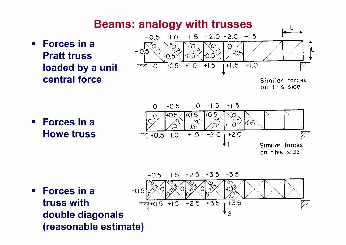
Beams: analogy with trusses
Forces in a Pratt truss loaded by a unit central force
Forces in a Howe truss
Forces in a truss with double diagonals(reasonable estimate)
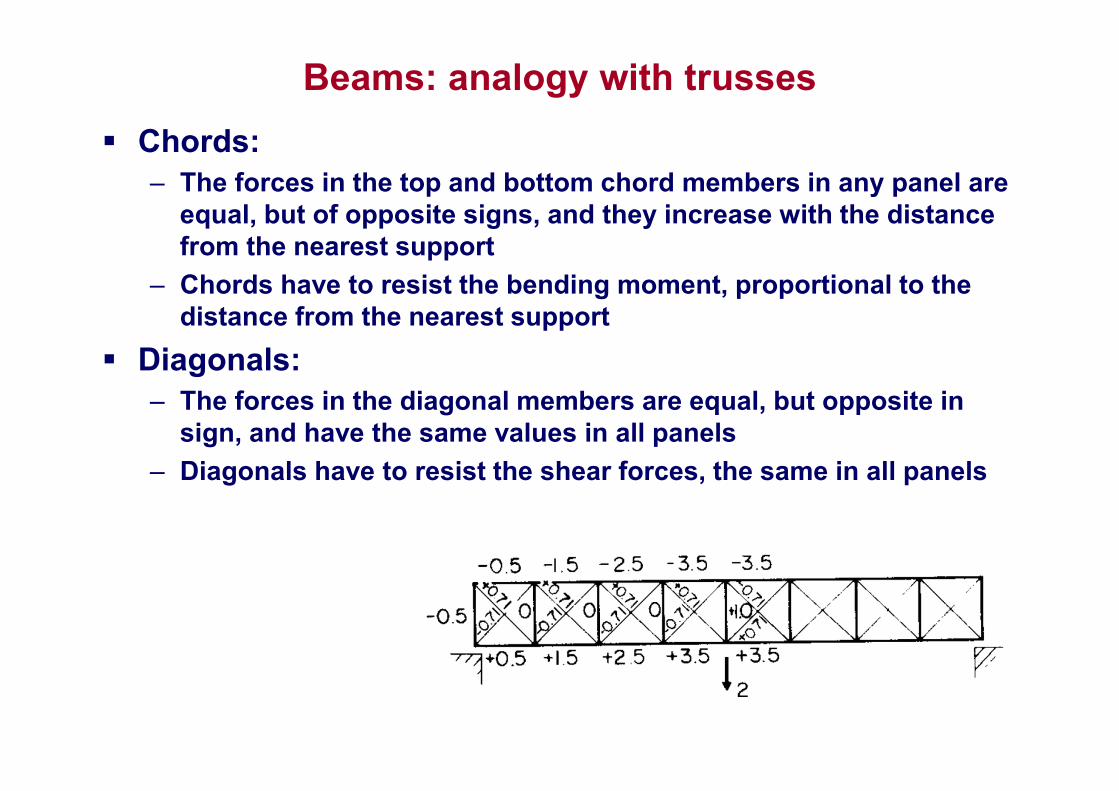
Beams: analogy with trusses
Chords:– The forces in the top and bottom chord members in any panel are
equal, but of opposite signs, and they increase with the distance from the nearest support
– Chords have to resist the bending moment, proportional to the distance from the nearest support
Diagonals:– The forces in the diagonal members are equal, but opposite in
sign, and have the same values in all panels
– Diagonals have to resist the shear forces, the same in all panels
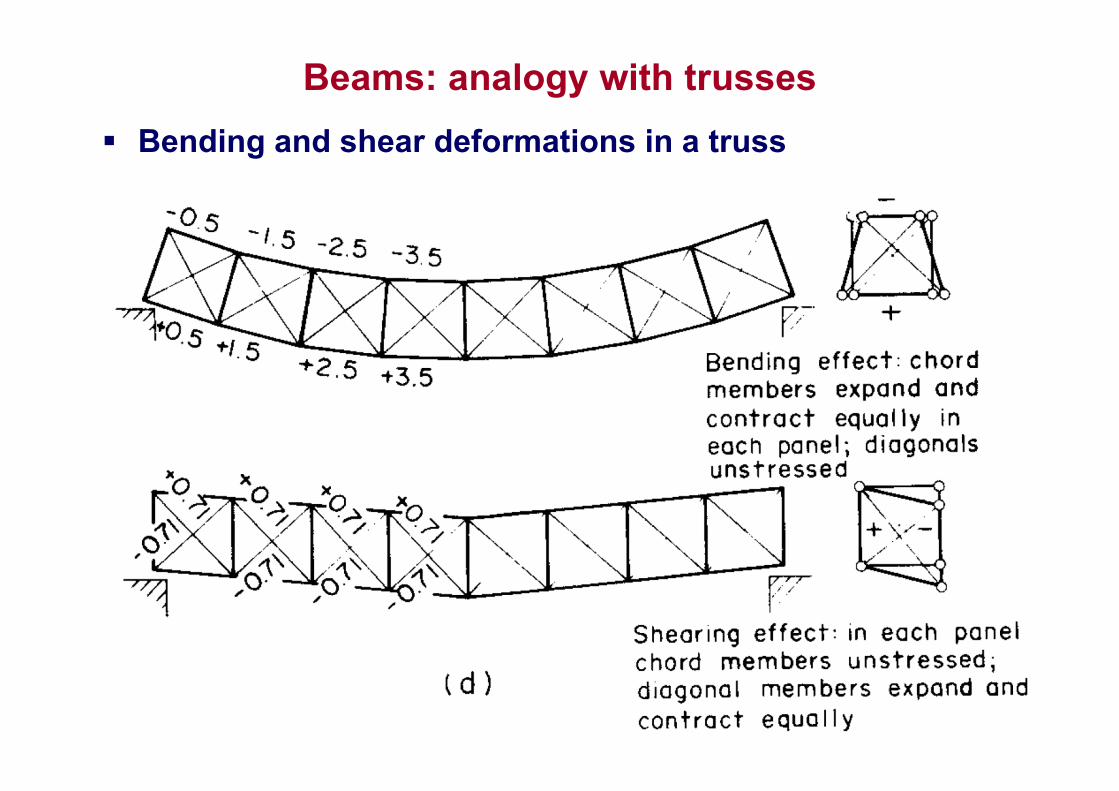
Beams: analogy with trusses
Bending and shear deformations in a truss
Steel plate girder
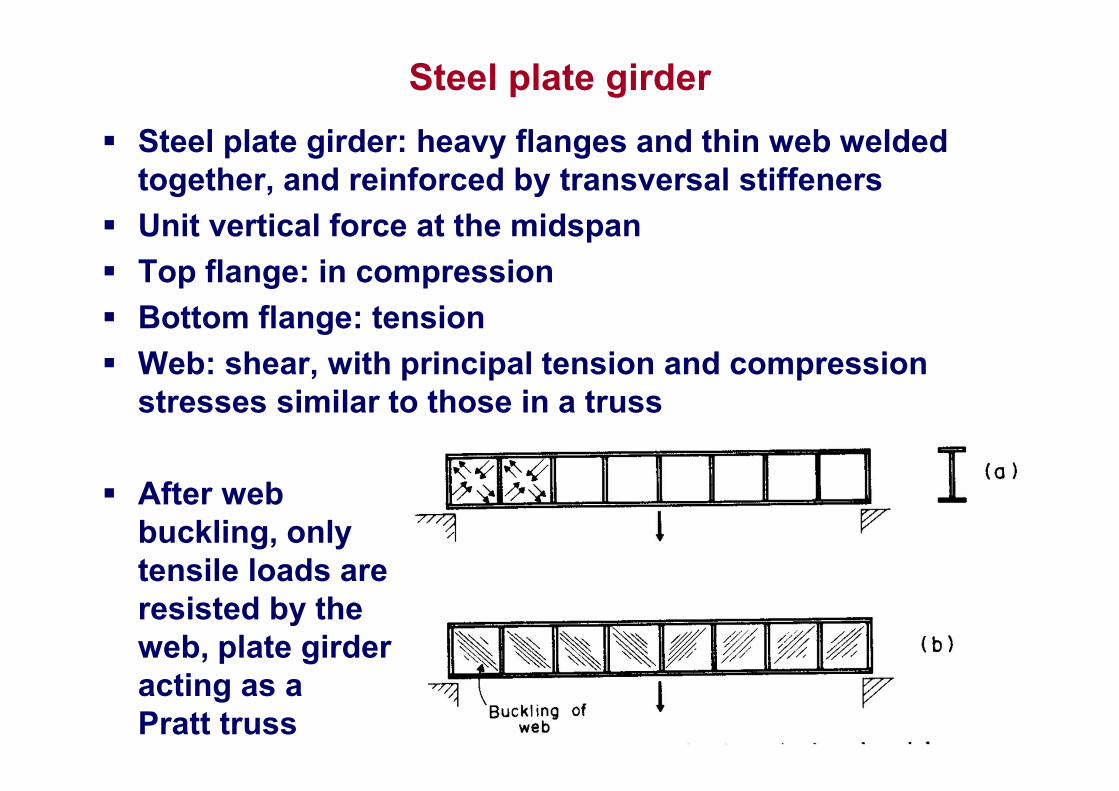
Steel plate girder: heavy flanges and thin web welded together, and reinforced by transversal stiffeners
Unit vertical force at the midspan
Top flange: in compression
Bottom flange: tension
Web: shear, with principal tension and compression stresses similar to those in a truss
After web buckling, only tensile loads are resisted by the web, plate girder acting as a Pratt truss
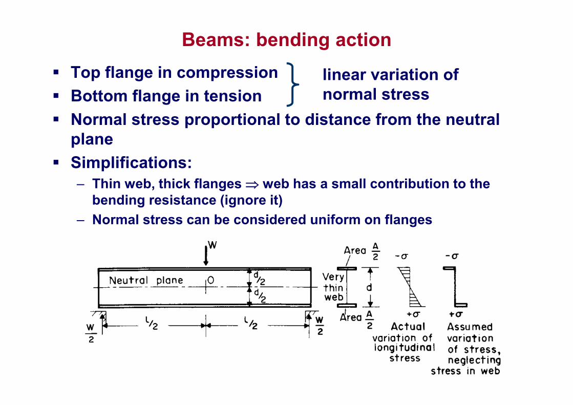
Beams: bending action
Top flange in compression
Bottom flange in tension
Normal stress proportional to distance from the neutral plane
Simplifications:– Thin web, thick flanges web has a small contribution to the
bending resistance (ignore it)
– Normal stress can be considered uniform on flanges
linear variation of normal stress
Beams: bending action
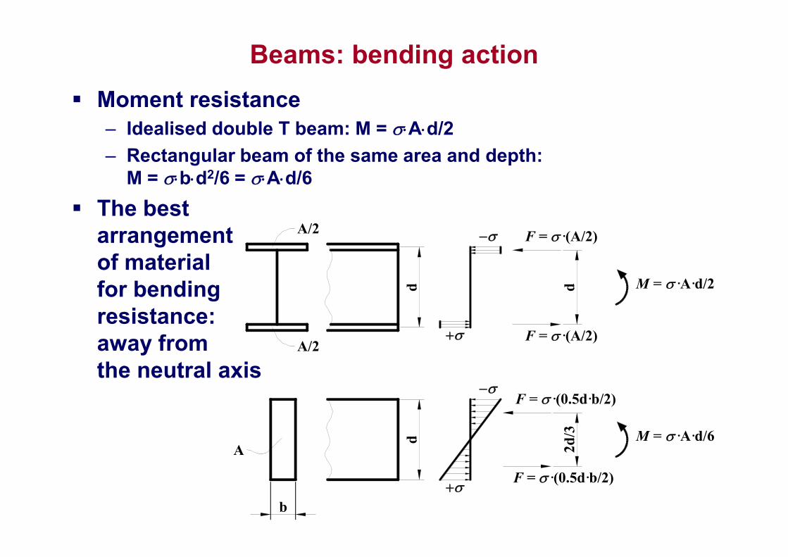
Moment resistance– Idealised double T beam: M = Ad/2
– Rectangular beam of the same area and depth: M = bd2/6 = Ad/6
The best arrangement of material for bending resistance: away from the neutral axis
d
F = ·(A/2)
F = ·(A/2)
d M = ·A·d/2
A/2
A/2
d
b
F = ·(0.5d·b/2)
F = ·(0.5d·b/2)
2d
/3 M = ·A·d/6A
Beams: bending action
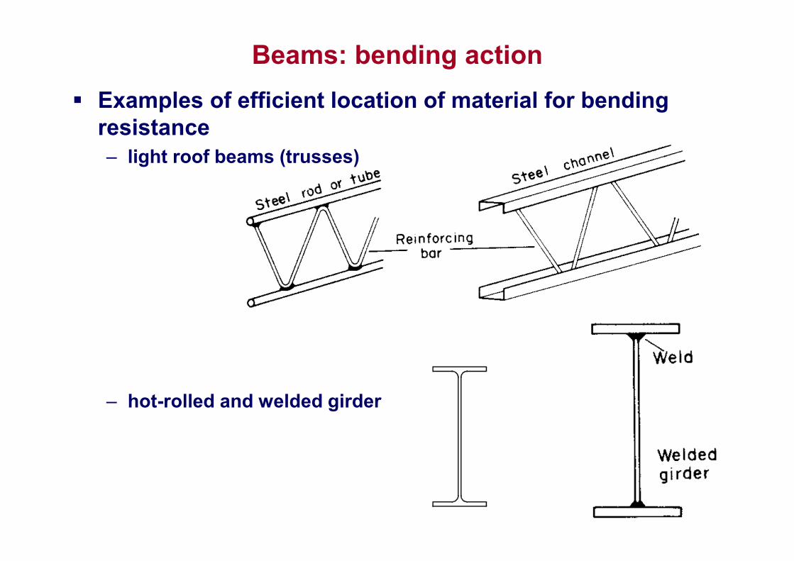
Examples of efficient location of material for bending resistance– light roof beams (trusses)
– hot-rolled and welded girder
Beams: bending action
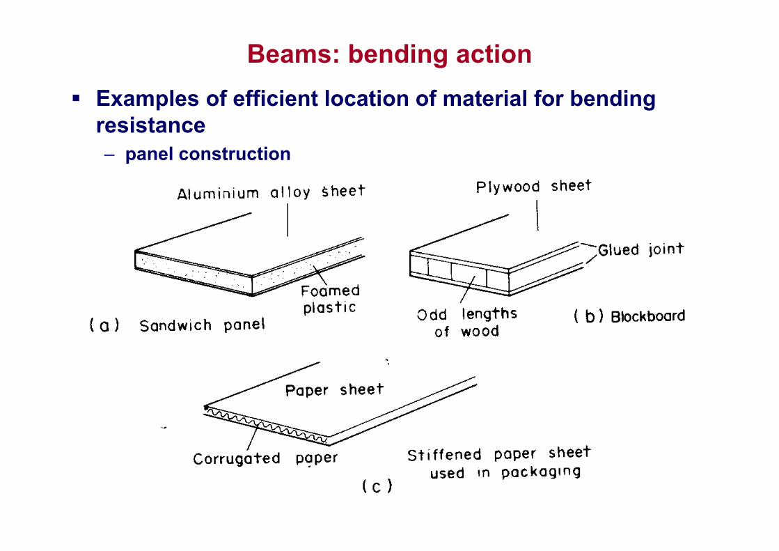
Examples of efficient location of material for bending resistance– panel construction
Beams: bending action
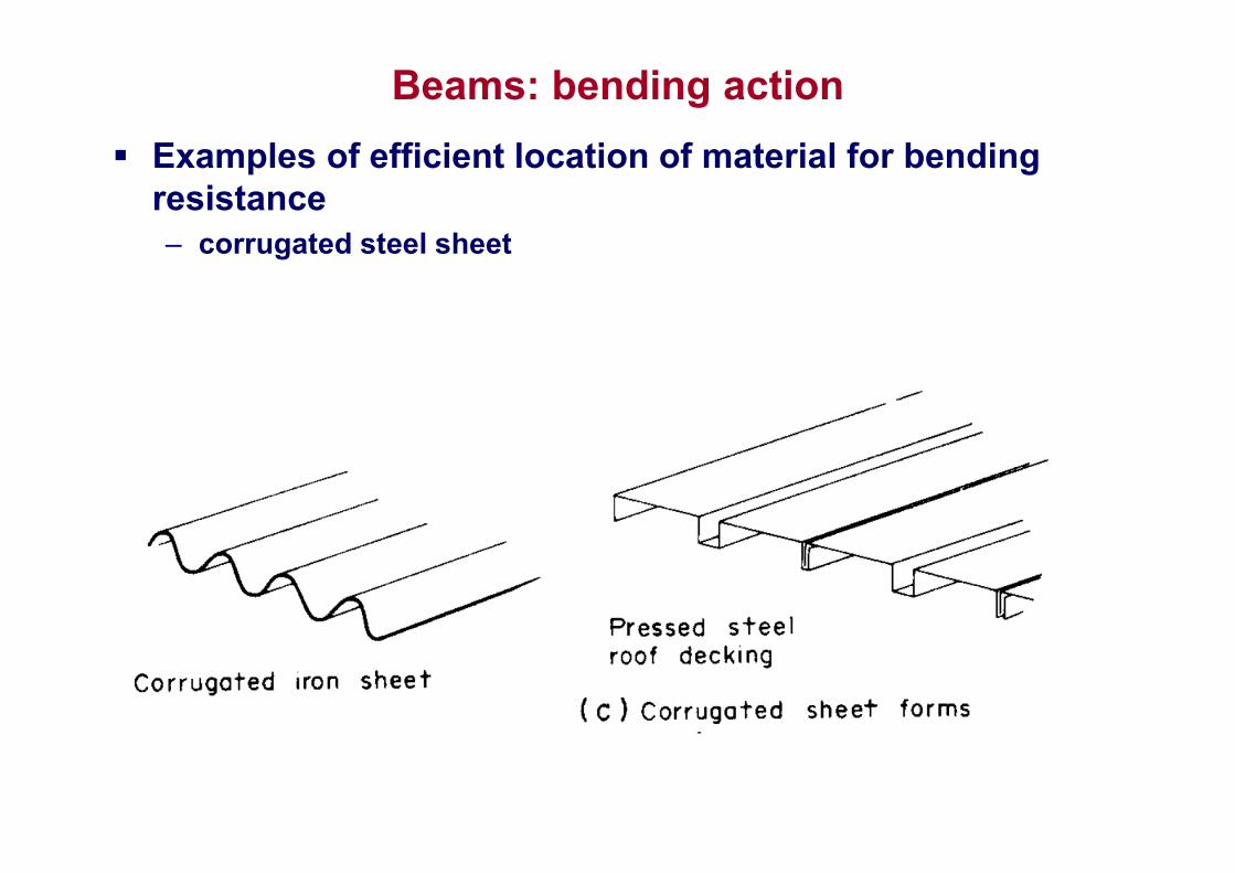
Examples of efficient location of material for bending resistance– corrugated steel sheet
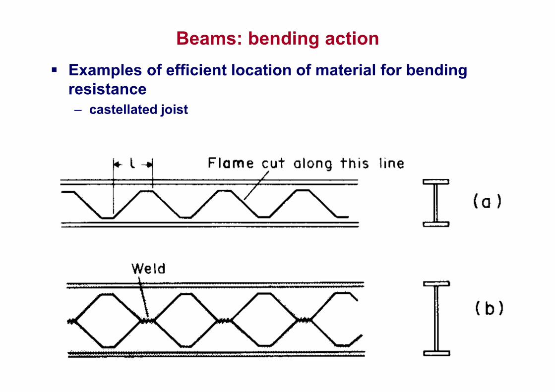
Beams: bending action
Examples of efficient location of material for bending resistance– castellated joist
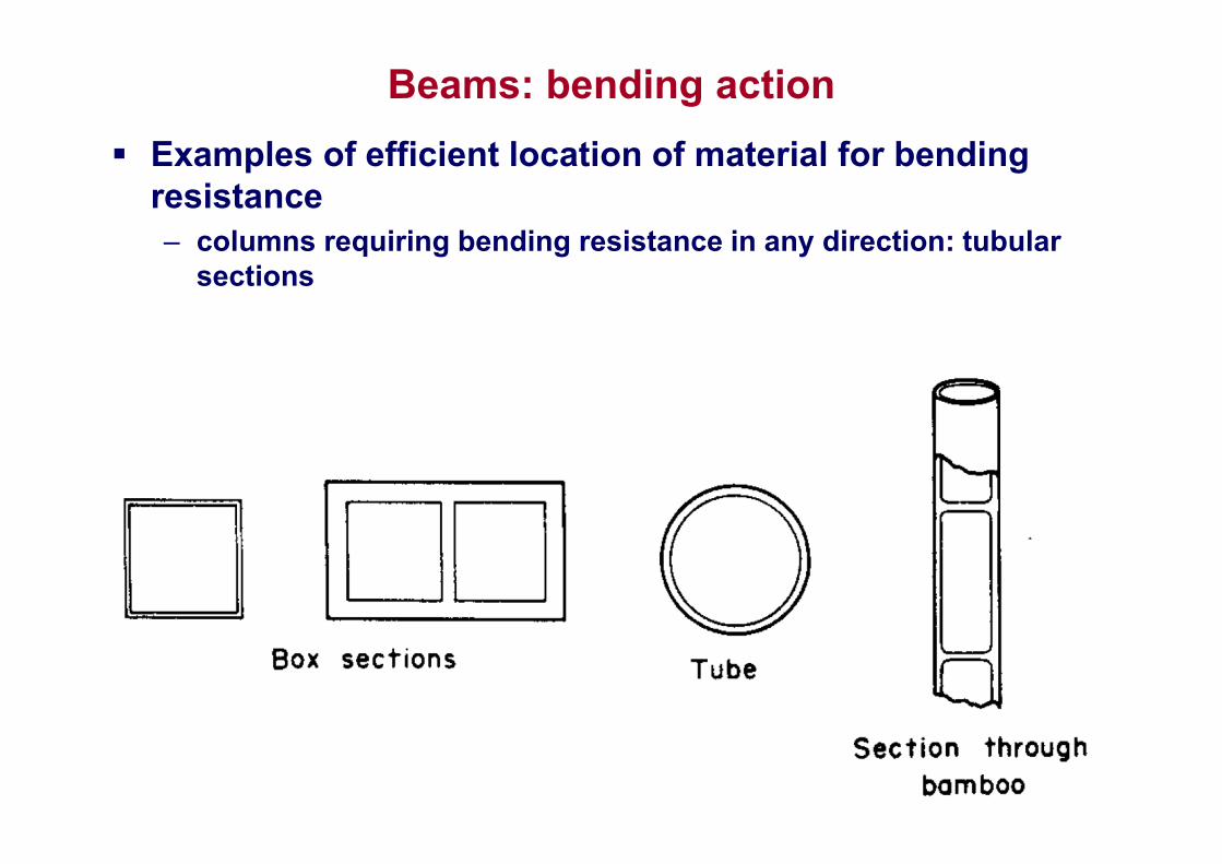
Beams: bending action
Examples of efficient location of material for bending resistance– columns requiring bending resistance in any direction: tubular
sections
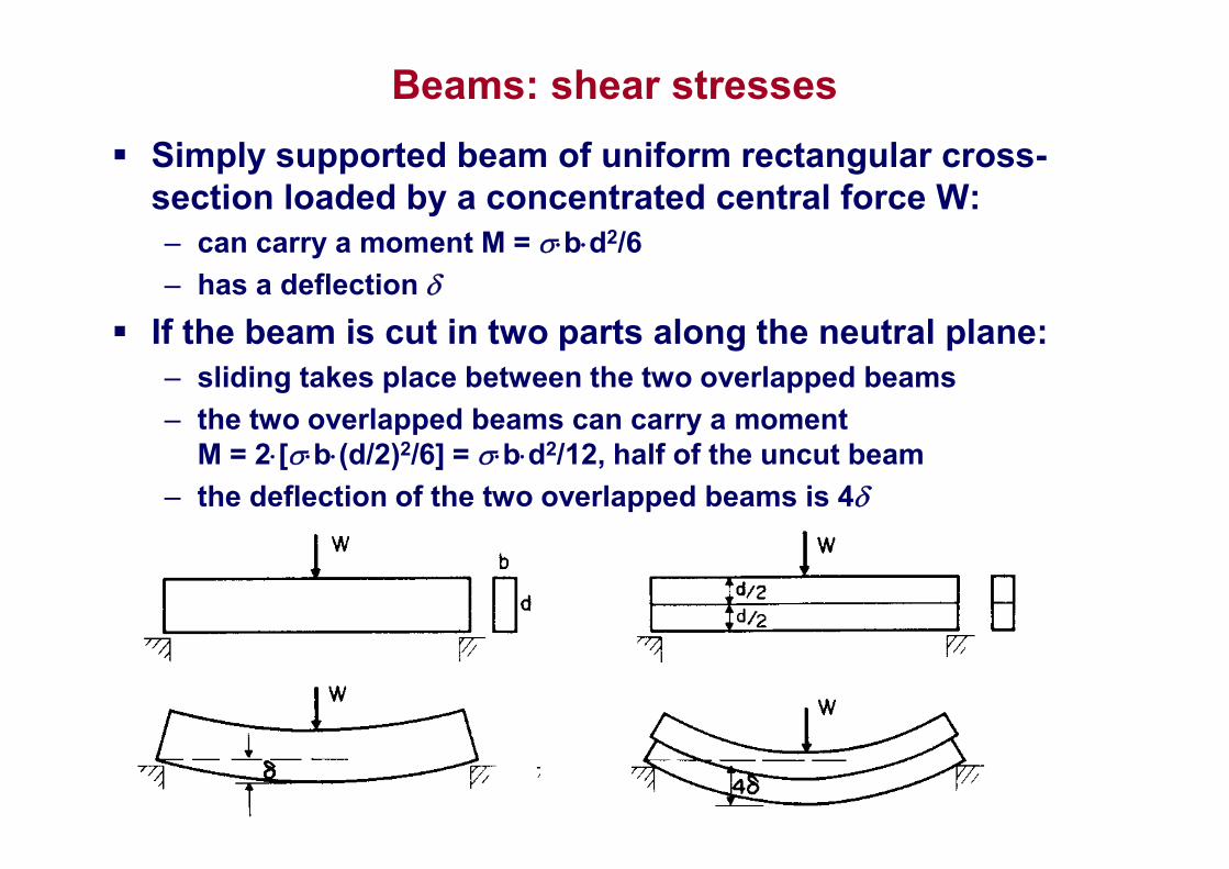
Beams: shear stresses
Simply supported beam of uniform rectangular cross-section loaded by a concentrated central force W:– can carry a moment M = bd2/6
– has a deflection
If the beam is cut in two parts along the neutral plane:– sliding takes place between the two overlapped beams
– the two overlapped beams can carry a moment M = 2[b(d/2)2/6] = bd2/12, half of the uncut beam
– the deflection of the two overlapped beams is 4
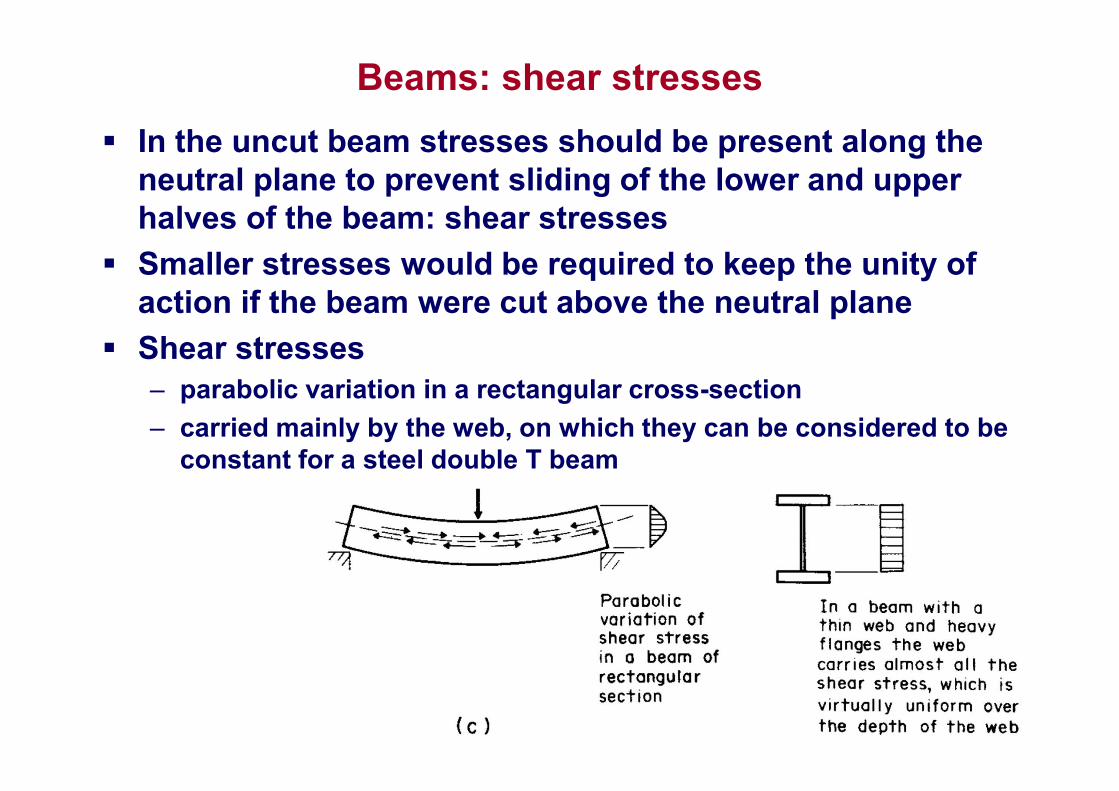
Beams: shear stresses
In the uncut beam stresses should be present along the neutral plane to prevent sliding of the lower and upper halves of the beam: shear stresses
Smaller stresses would be required to keep the unity of action if the beam were cut above the neutral plane
Shear stresses – parabolic variation in a rectangular cross-section
– carried mainly by the web, on which they can be considered to be constant for a steel double T beam
Structural shapes
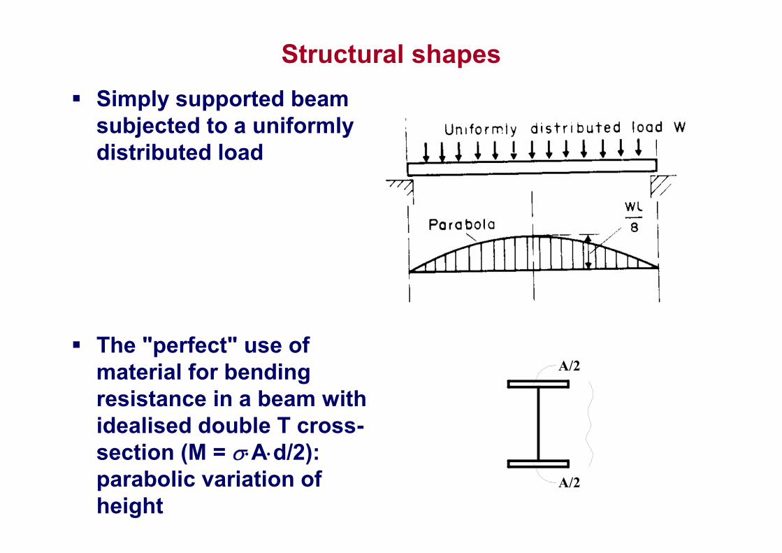
Simply supported beam subjected to a uniformly distributed load
The "perfect" use of material for bending resistance in a beam with idealised double T cross-section (M = Ad/2): parabolic variation of height
A/2
A/2
Structural shapes
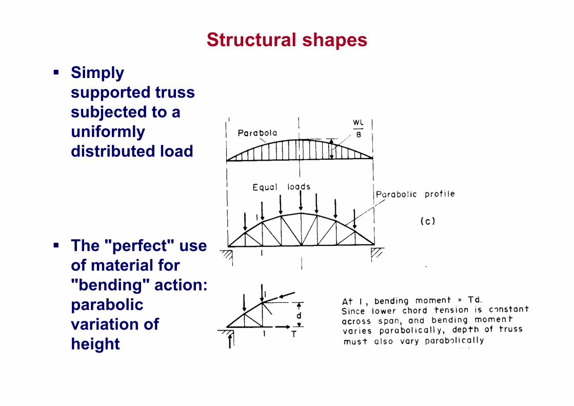
Simply supported truss subjected to a uniformly distributed load
The "perfect" use of material for "bending" action: parabolic variation of height
Structural shapes
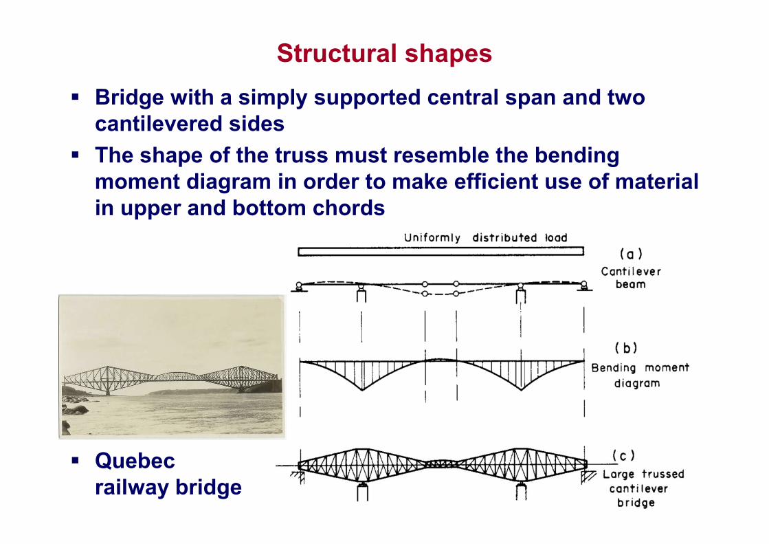
Bridge with a simply supported central span and two cantilevered sides
The shape of the truss must resemble the bending moment diagram in order to make efficient use of material in upper and bottom chords
Quebec railway bridge
Structural shapes
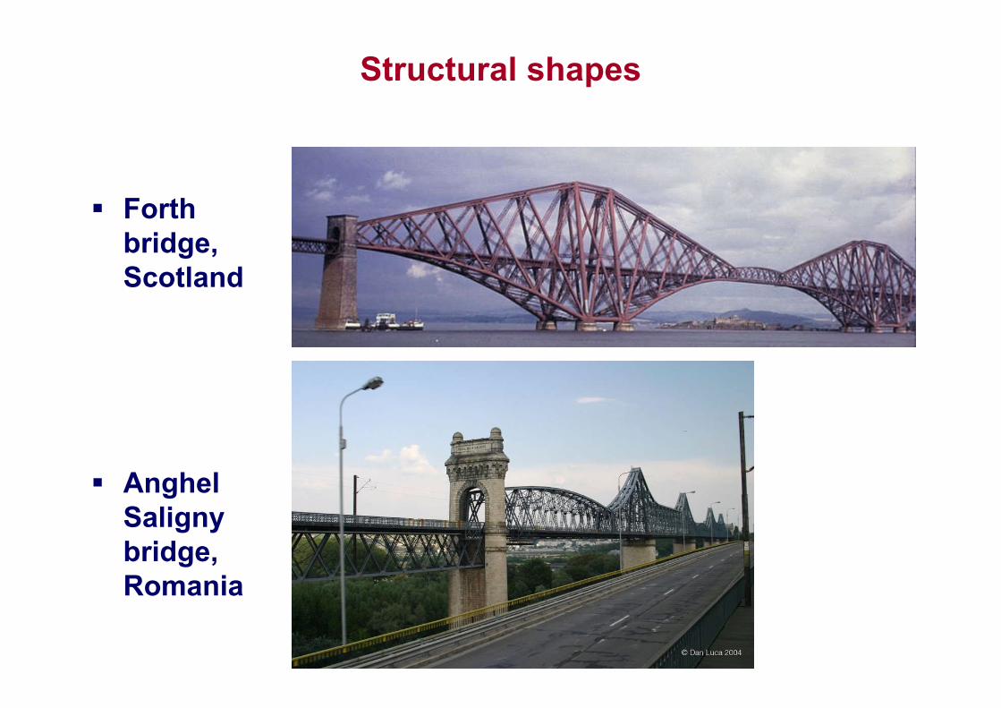
Forth bridge, Scotland
Anghel Salignybridge, Romania