Basics of CT
101
-
Upload
mohamed-shaaban -
Category
Health & Medicine
-
view
123 -
download
2
Transcript of Basics of CT


•Principle of Raw Data.
•Terms used in CT.
•Image processing.

The X-Ray Concept
• Electrons Gush.
• Object.
• Film/Screen.
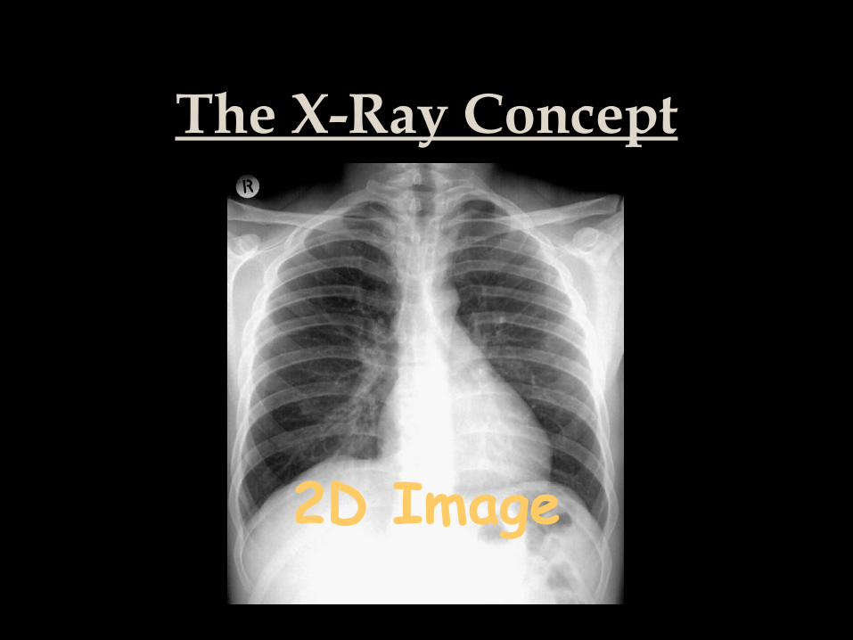
The X-Ray Concept
2D Image

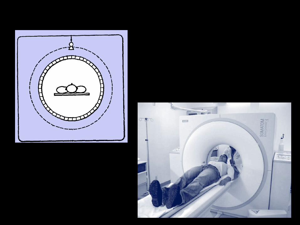
CT
• Stronger X-Ray.
• Rotating Tube.
• A Row of Detectors.

Tube
Object
Detectors
COMPUTERFilm

Raw Data

Field of View(FOV)


10 volt.75 HU
A6 + B6 + C6 + D6 + E6 + F6 + G6 = 75 HU
12 volt.90 HU
A7 + B7 + C7 + D7 + E7 + F7 + G7 = 90 HU
20 volt.102 HUA8 + B8 + C8 + D8 + E8 + F8 + G8 = 102 HU
30volt.
307 HUD1 + D2 + D3 + D4 + D5 + D6 + D7 = 307 HU
43 volt.
360 HU
E1 + E2 + E3 + E4 + E5 + E6 + E7 = 360 HU

X + Y = 8
X + Z = 10
Y + Z = 12
X = 3
Y = 5
Z = 7
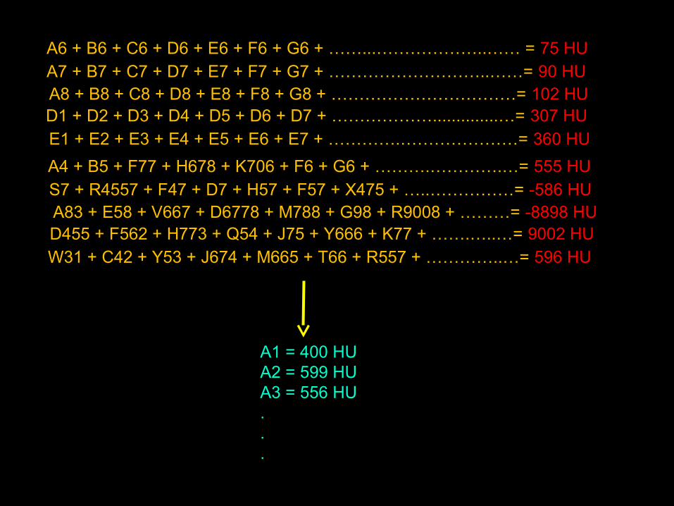
A6 + B6 + C6 + D6 + E6 + F6 + G6 + ……...………………..…… = 75 HU A7 + B7 + C7 + D7 + E7 + F7 + G7 + ………………………..……= 90 HU A8 + B8 + C8 + D8 + E8 + F8 + G8 + ……………………………= 102 HU D1 + D2 + D3 + D4 + D5 + D6 + D7 + ………………..............…= 307 HU E1 + E2 + E3 + E4 + E5 + E6 + E7 + ………….…………………= 360 HU
A4 + B5 + F77 + H678 + K706 + F6 + G6 + ……….………….…= 555 HU S7 + R4557 + F47 + D7 + H57 + F57 + X475 + …..……………= -586 HU A83 + E58 + V667 + D6778 + M788 + G98 + R9008 + ………= -8898 HU D455 + F562 + H773 + Q54 + J75 + Y666 + K77 + …….…..…= 9002 HU W31 + C42 + Y53 + J674 + M665 + T66 + R557 + …………..…= 596 HU
A1 = 400 HUA2 = 599 HUA3 = 556 HU...

1. Attenuation Value (HU): White/Grey/Black.
2. Place: X-Y-Z.

X
Y Z
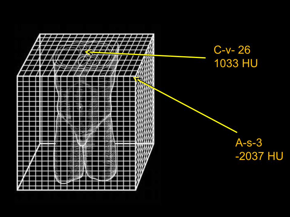
A-s-3-2037 HU
C-v- 261033 HU


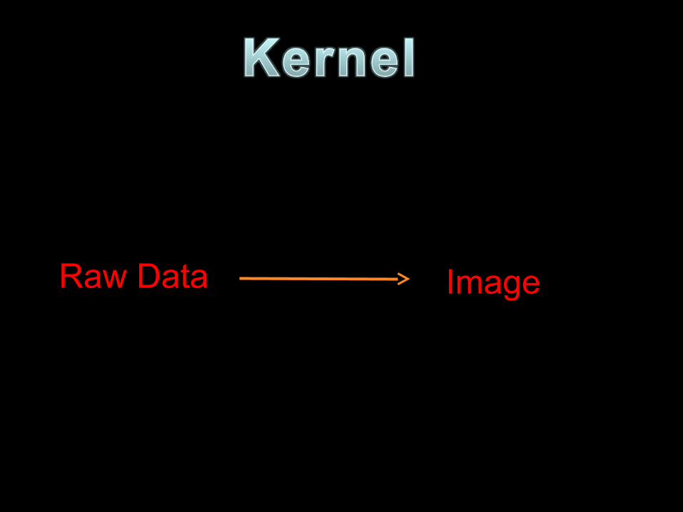
Raw Data Image

Raw Data

Image Image


- 3000 30000

- 3000 30000
Center
20 HU
500 500Width
- 480 HU 520 HU

- 3000 3000
Center
20 HU
Width
- 480 HU 520 HU

- 30003000
Center
70 HU
Width
- 10 HU 150 HU
80

- 30003000
Center
-1000 HU
Width
- 1900 HU -100 HU
900

Field of View(FOV)


0.5 mm


19 10 20 -99 -19 -20 -88 -56 75 22 77 265 154 332143 31
5 mm
Volume Average Artifact

Voxel Pixel


Pixel


Collimation

Collimation
• 1 mm.→ 10 – 5 – 2 – 1 – 0.75 mm.
• 2 mm.→ 10 – 5 – 2 – 1 mm.
• 3 mm. → 10 – 5 – 2 mm.

Collimation
1 mm.
2 mm.
3 mm.

Collimation
▲Collimation ( Beam Width)→
▲ scan time
▲ exposure
▲ motion artifact
▲ thinnest possible slice thickness

Table Increment


Pitch
• T = table increment.• W = beam width (collimation).
Pitch = T/W

Pitch
• Table increment = 10 mm.• Width = 10 mm.
Pitch = 1
Pitch = T/W

Pitch = 1
• NO GAP
• NO OVERLAP
10 mm.
10 mm.

Pitch
• Table increment = 5 mm.• Width = 10 mm.
Pitch = 0.5
Pitch = T/W

Pitch = 0.5
• NO GAP
• OVERLAP
5 mm.
10 mm.

Pitch
• Table increment = 10 mm.• Width = 5 mm.
Pitch = 2
Pitch = T/W

Pitch = 2
• GAP
• NO OVERLAP
10 mm.
5 mm.
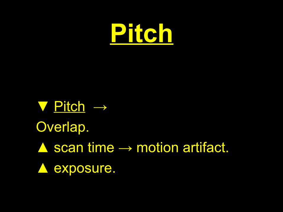
Pitch
▼ Pitch →
Overlap.
▲ scan time → motion artifact.
▲ exposure.


Break


• Reconstruction =
Raw Data Axial / Coronal / Sagittal images.→
• Reformatting =
(Axial) Images Coronal / Sagittal Images.→

Multi-Planar Reformatting
MPR

Multi-Planar ReformattingMPR

MPR

MPR
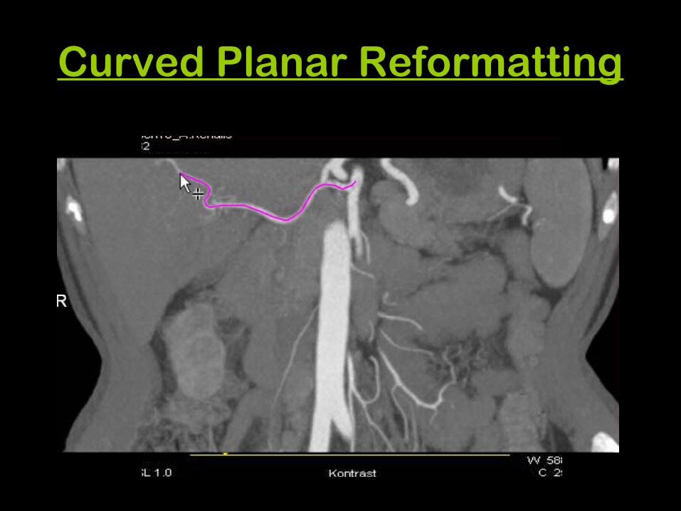
Curved Planar Reformatting

Curved Planar Reformatting

Curved Planar Reformatting

Curved Planar Reformatting

Curved Planar Reformatting

Curved Planar Reformatting

Maximum Intensity Projection
MIP

MIP

MIP
23 -10 38 103 232 -100 10 1 12 4 232

MIP

MIP

MIP

MIP

23 -10 38 103 232 -100 10 1 12 4 -100
MinIP

MinIP
MIP Min IP

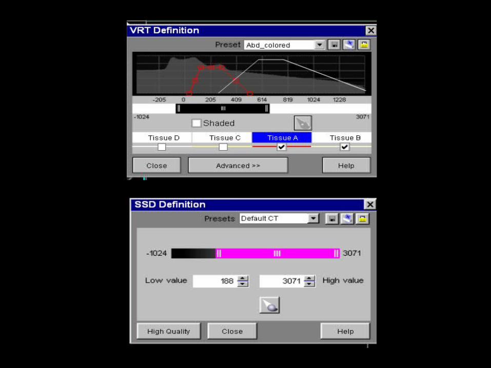
Surface Shaded Display
SSD

Surface Shaded DisplaySSD

Surface Shaded DisplaySSD

Surface Shaded DisplaySSD
280
276
170

Surface Shaded DisplaySSD

Surface Shaded DisplaySSD

Volume Rendering Technique
VRT

Volume Rendering TechniqueVRT

Volume Rendering TechniqueVRT


Volume Rendering TechniqueVRT

Volume Rendering TechniqueVRT

Volume Rendering TechniqueVRT

VIRTUAL ENDOSCOPY

VIRTUAL ENDOSCOPY
The voxels located on the edge of a structure are identified, usually by intensity thresholding, and these voxels are displayed. The remaining voxels in the image are usually invisible.

VIRTUAL ENDOSCOPY

VIRTUAL ENDOSCOPY

VIRTUAL ANGIOSCOPY

VIRTUAL NEPHROSCOPY

Image Display
• MPR / Curved MPR.
• MIP / Min IP.
• SSD.
• VRT.
• Virtual Endoscopy.

THANK YOU