


Digitale kundeoplevelser den 29. januar - Morten Schroeder, Wilke

BASIC TIGER®
Device Driver Manual

.

About this manual 1Device driver 2Applications 3BASIC Tiger® Graphic Toolkit 4Frequently asked questions 5Index 6Appendix 7

Editor Klaus HiltropIllustrations JojiCover Werbeagentur Kordoni, AachenEdition 5th Edition Juli 2001 - Version 5.0
Copyright © 1994-2001 by Wilke Technology GmbHKrefelder Str. 14752070 Aachen / Germany
This manual, together with the hardware and software which itdescribes, is copyrighted and may not be in any way copied,translated or rendered in any other form without the expresswritten consent of Wilke Technology GmbH.
Trademarks BASIC Tiger®, TINY Tiger®, TigerCube® are registeredtrademarks of Wilke Technology GmbH.TouchMemory® is registered trademark of DallasSemiconductors.WindowsTM, Windows 95, Windows NT are registeredtrademarks of Microsoft Corp.
The names of products and processes in this publication, whichare at the same time trademarks, have not been specificallyidentified as such. These names are trademarks of therespective trademark owners. Simply because the ® sign ismissing, it cannot be concluded that these names are freecommodity names.
Note The editors, translators and authors of this publication havetaken great care with the texts, illustrations and programs.Nevertheless, errors cannot be completely excluded. WilkeTechnology thus assumes no warranty, legal responsibility orliability for consequences resulting from incorrect information.Should any errors be discovered in this publication, or in thesoftware, we welcome any comments and suggestions
The information in this manual should not be regarded as awarranty of certain product properties or features, and is subjectto change in the interests of technical improvement.
All rights reserved • Printed in GermanyPrinted on chlorine-free bleached paper

List of contents
Wilke Technology GmbH • www.wilke-technology.com • eMail: [email protected] i
List of contents1 About this manual 3
Device driver 3New device drivers in Version 5.0 5What was new in version 4 6How this manual is organized 7Typographic conventions and symbols 8BASIC Tiger® 9
Multitasking 10Functions 11
2 Device driver 15
Standard pin usage of device drivers 17Device driver functions 19
Inquire level of a buffer 20Inquire free space in a buffer 21Delete buffer content 23Inquire version number of the driver during running time 25Device driver warning codes 27Device driver error codes 28
A/D-Inputs with Analog1 31A/D-Inputs with Analog2 33
User-Function-Codes ANALOG2.TDD 35Measuring into FIFO 37Measuring into a String variable 39Measuring with 12-bit resolution 42Set sample rate 43
A/D inputs with Analog3 45Secondary addresses of the ANALOG3.TDD 47User-Function-Codes of the ANALOG3.TDD 48Scale measurement range 48Adjust input voltage range 51Define channel groups 52Delete channel group 52Read A/D-value singly and from a channel group 53
LCD panel and keyboard 55ESC-Commands 56

List of contents
Wilke Technology GmbH • www.wilke-technology.com • eMail: [email protected]
LCD Panel 57Type list 59Connect LCD Panel 61User-Function-Codes (LCD) 62Control characters of the LC-display 63ESC-Commands LC-display: 64Position cursor: ESC A 65Activate special character set: ESC S 67Load special character set: ESC L 69Reset special character set: ESC R 71Menu on the LCD Panel: ESC M 73Define cursor: ESC c 75LCD Panel - Special character sets 76Pre-defined special character sets 78
LCD1 Keyboard 87User-Function-Codes keyboard 87ESC commands keyboard: 90Keyboard-Auto-Repeat: ESC r 91Key codes: ESC Z or. ESC z 93Key attributes: ESC a 94DIP-switch: ESC D 96Reading in DIP-switches 98Scan addresses: ESC k 99
Sound 101ESC-command Sound 101Deactivate sound: ESC C 103Beep: ESC B 105Key click: ESC K 107Control character tone 109
LCD-6963 - Graphic display 111Type list LCD-6963 113Connecting the graphic LC-display 114User-Function-Codes LCD-6963.TDD 115Control characters of the graphic LC-display 117ESC commands LCD-6963 (Text) 118
LCD-6963 Position cursor: ESC A 120LCD-6963-Mode: ESC m 121Graphic display on / off: ESC G 123Text display on / off: ESC T 125LCD-6963 Define cursor: ESC c 126

List of contents
Wilke Technology GmbH • www.wilke-technology.com • eMail: [email protected] iii
LCD-6963 - Special character set 128LCD-6963 graphics 131
Output on the graphic screen 132Graphic LCD functions (overview) 135
MF-II-PC Keyboard 137Parallel printer 143Parallel input 147
User-Function-Codes of PIN1.TDD 149Pulse I/O 151Count pulses 153Encoder 158
Secondary addresses of ENC1.TDD 159User-Function-Codes of ENC1.TDD 160Connecting an Encoder 161Dynamic counter 162
Frequency meter 165Measure pulse lengths with high resolution 169Measure pulse lengths with TIMERA 173Output pulse with high resolution 177
User-Function-Codes of PLSOUT1.TDD 178Output pulse with TIMERA 181
Secondary addresses of PLSO2_xx.TDD 182User-Function-Codes of PLSO2_xx.TDD 182
PWM1 (Pulse width modulation) 185PWM2 (Pulse width modulation) 189
PWM output 191User-Function-Codes of PWM2.TDD 193Setting the Output-rate 195Over-sampling 196Using the Reload-Buffer 197Sound output with PWM2 199
SER1B - Serial interfaces 201User-Function-Codes of SER1B_xx.TDD 206Handshake 209
Output 209Output and controlling the buffer 210Input characters 210RS-485-Mode 213RS-485 in 9-Bit mode 217
Master and Slave with 9-bit addresses 218

List of contents
Wilke Technology GmbH • www.wilke-technology.com • eMail: [email protected]
SER2 - Serial interfaces through software 223User-Function-Codes of the SER2_xx.TDD 227
SER4 - Serial direct in strings with up to 614200baud 233Check the data flow in the DACC mode 236Data output in the DACC mode 238Data output with Reload in the DACC mode 239Data receipt in the DACC mode 242Data receipt with Reload in the DACC mode 244
CAN 247Description of the device driver CAN1_xx.TDD 247CAN messages in the I/O-buffer of the driver 250
Standard frame 251Extended Frame 253
CAN User-Function-Codes 255Bus-Timing and transfer rate 257
Bustiming-Register 0 258Bustiming-Register 1 258
Error Register 260Arbitration-Lost error 262ECC Error Register 263RXERR receive error counter 265TXERR send error counter 265
Receive filter with Code and Mask 266Set Access-Code and Access-Mask 266Standard-Frame with Single-Filter configuration 270Extended Frame wit Single-Filter configuration 275Standard-Frame with Dual-Filter configuration 279Extended-Frame with Dual-Filter configuration 283
Sending CAN messages 287Receive CAN messages 291I/O buffer 297Automatic bit rate detection 299CAN-bus hardware connection example 302A short introduction to CAN 303Special features of the BASIC-Tiger®-CAN module 305Error situations 306References to CAN 307
CAN-SLIO Board 308CAN-SLIO Board 309CAN-SLIO chip 311

List of contents
Wilke Technology GmbH • www.wilke-technology.com • eMail: [email protected] v
Identifier of the SLIO 311Automatic bit rate detection 311SLIO message format 312
Finding SLIOs on the bus 314Some special features for interested parties 322
Remote Frames 322Bit-Timing 322Oscillator and calibration 322Initialization 323Sign-On Message 323
Register overview 324SLIO Digital I/O's 325SLIO analog outputs 332Analog configuration 338Starting the A/D conversion 341Two SLIOs on one bus 347
Touch-Memory 353Real-Time-Clock / Clock 359Time-base Timer 365SET1.TDD 375RES1.TDD 377
3 Applications 381
Plug & Play Lab keyboard customization 382Program "Version" 385Program "KEY_NO" 387Program "LCD_SPCC" 388Program "LCD_SPC4" 389Program "SER1_DEM" 391Program „Ana1_Dem“ 393Program „Serial, 8x“ 396Step motor with PLSO2 397Music with PLSO1 409
4 BASIC-TIGER® Graphic Toolkit 417
Graphic LC display 421Large numbers 426Mini keyboard 429Serial interfaces 434
Mouse 435

List of contents
Wilke Technology GmbH • www.wilke-technology.com • eMail: [email protected]
Printer port 444Analog inputs 446Photoresistor 448
Measuring instrument 453Oscilloscope 456Oscilloscope recorder 458Encoder 463Touchpanel 475
Touchpanel Cursor 482Touchpanel as keyboard 485Touchpanel as keyboard with ANALOG2.TDD 489Touchpanel as complete keyboard 495
5 Frequently asked questions 507
Tips and assistance 511BASIC Tiger®-Service-Hotline: 511
6 Index 515
7 Appendix 521
ASCII codes 521EBCDIC codes 522The Baudot Code Set 523Gray Code 524ANSI Control Sequences 525Windows 95/98/NT Shortcuts 527Short-Cuts Tiger-BASIC® Version 5 529Designation of resistors and capacitors 531
Color codes 531Value designation by characters 532Tolerance designation by characters 533Medium step size of resistor-growth between values: 535Normed series of resistor values 535
BASIC-Tiger® module A – Pin description 543TINY-Tiger® – Pin description 547TINY-Tiger® Modul E – Pin description 551BASIC-Tiger® CAN module – Pin description 555
Wilke Technology GmbH • www.wilke-technology.com • eMail: [email protected] 1
About this manual 1Device driver 2Applications 3BASIC Tiger® Graphic Toolkit 4Frequently asked questions 5Index 6Appendix 7

About this manual
Wilke Technology GmbH • www.wilke-technology.com • eMail: [email protected]
1
3
1 About this manualWelcome to the BASIC Tiger® development system.
This manual will introduce you to programming the BASIC Tiger® and will help youget off to a quick start.
Programming micro-controllers used to be the domain of specialists. Theprogramming itself generally took place in Assembler, which meant that the programswere fast, but difficult to understand. The development work for even small projectsoften dragged on for months. If BASIC was chosen as a programming language theprocessing speeds were relatively slow and with limited possibilities.
BASIC Tiger® fills this gap. The innovative modified BASIC instruction set makesprogramming very simple and reduces the familiarization period. BASIC Tiger® has avery high processing speed and thus puts many controllers, which have beenprogrammed in Assembler or C to shame. Multitasking, with no complicatedoverheads, leads to better-structured and easier to care for programs. A growinglibrary of functions and example applications is available for repetitive programmingtasks. Since the BASIC Tiger® supports device drivers that are constantly beingupdated, it can grow with the project and thus cope with tasks that had not even beenthought of at the start of the project.
If you want to start programming immediately, follow the instructions for installationand then go directly to the "Quick start/First steps" section.
Device driverDevice drivers extend Tiger BASIC®, by using I/O functions that allow externaldevices to be used easily. Instead of using numerous BASIC instructions for variousI/O devices, which may be new to the user, all peripheral equipment can be controlledwith the following BASIC instructions:
• PRINT• PRINT_USING• PUT• INPUT• INPUT_LINE• GET

About this manual
Wilke Technology GmbH • www.wilke-technology.com • eMail: [email protected]
1
4
These instructions only work on an external device when used in conjunction with anI/O device driver. The device driver knows the device-specific characteristics andforms the user-device interface. Different devices can react differently to PUTinstructions. For example, a Robot-Arm changes its position, an analog outputmodifies its value, a modem generates a corresponding audio sequence, etc. Thesedifferent characteristics are taken into account by the device driver, not in the BASICsyntax.
Certain device drivers need specific pins or ports. Consequently, these are thenblocked to IN and OUT instructions. A number of device drivers can also share anI/O-pin, e.g. in the form of a bus.
To ensure that a certain device driver is available in a program, it is installed at thebeginning of the MAIN task. During installation with the instruction,INSTALL_DEVICE, the device driver is assigned a number as a device number. Thepreviously mentioned I/O instructions always address the device driver through thisdevice number.
The device number in the I/O instructions can also be a variable. This enables flexibleI/O management. The data flows can easily be diverted to other devices if necessary.
Input and output instructions often use secondary addresses, function codes andcommands to control the device via the driver.
Secondary addresses, like in-house telephone numbers, select a certain channelof a device. Device drivers can, but do not have to support secondary addresses. If, forexample, a device driver has 4 channels, the secondary address specifies one of the 4channels. Device drivers can also have virtual channels, which are addressed by asecondary address. Control information can be written in these channels, or statusinformation read from them. Their mode of operation depends on the respectivedevice driver. Details can be found in the descriptions of the device drivers.
Function codes can be used to execute control functions or to obtain statusinformation from the device. A device driver's description determines if functioncodes are supported and if so, which ones.
���

About this manual
Wilke Technology GmbH • www.wilke-technology.com • eMail: [email protected]
1
5
New device drivers in Version 5.0If you are already an experienced Tiger-BASIC® user you will definitely be interestedin the new developments. The following is a brief summary of the most importantnew developments in the device driver sector since the last update. You will find thenew sections of the last but one update in the next heading ‘What was new inversion 3’. New instructions, functions and device drivers are listed in the other twomanuals.
Further device drivers have been added.
ANALOG3 - A/D-driver for analog module EP11......................................45MF2 - MF-II-PC-Keyboard ......................................................................137SER2 - Serielle Schnittstellen: durch Software.......................................223SER4 - Seriell direkt in Strings mit bis zu 614200baud ..........................233CAN1_xx – CAN-Bus-Treiber für Modul TCAN ......................................247
Some of the existing device drivers have been given extended functions:
• The RTS0 pin of the SER1B_nn.TDD can now be set with a User-Functioncode.
• The Encoder appears dynamically when the device driver is transferred to atable. Fast turning then creates more steps than the decoder has actuallyproduced. Additionally, this speed information can be read out.
• PLSO1 now uses a WORD variable for the number of pulses (previouslyLONG).

About this manual
Wilke Technology GmbH • www.wilke-technology.com • eMail: [email protected]
1
6
What was new in version 4More device drivers have been added.
Apart from the driver TMEM1.TDD all new drivers work together withTIMERA.TDD. The time-base driver TIMERA ensures that the appended devicedrivers perform their task irrespective of BASIC in the background. A number ofdrivers can be coupled to the time base simultaneously.
CNT1 - Counter ......................................................................................153ENC1 - Encoder......................................................................................158FREQ1 – Frequency meter.....................................................................165PLSI2 - Pulse length measuring .............................................................173PLSO2 - Pulse output .............................................................................181TMEM - TouchMemory ...........................................................................353SET1.TDD – CPU load testing ...............................................................375RES1.TDD – CPU load testing ...............................................................377
Some of the existing device drivers have been given extended functions:
• LCD1 can be installed a number of times. Moreover both LCD and keyboardscan can be deactivated separately.
• LCD1: there is now a reset command for new initialization.• SER1 now supports the RS-485 mode, including addresses with a set 9th bit.• PWM2 now accepts not only strings but also addresses in the Flash so that
the voice data can be output directly from the Flash (with no PEEK in string)for a voice output.
• Some buffered device drivers have different sized buffers. The size of thebuffer can be found in the file name.
• Output on a graphic LC-display is now largely supported, though byfunctions (see chapter 'Graphics' in the programming manual). A graphictoolkit is also being prepared on which special developments with graphicLCD can be carried out. Please take a look at our current advertising andinternet pages (www.wilke-technology.com).
About this manual
Wilke Technology GmbH • www.wilke-technology.com • eMail: [email protected]
1
7
How this manual is organizedA brief overview of the manual will help you to quickly find what you are lookingfor.
Chapter 1 is a short introduction.
Chapter 2 describes the device drivers. The device drivers provideelementary support using I/O-devices like LCD's, printers,ADC, PWM-output, etc.
Chapter 3 provides applications that may be run immediately on thePlug & Play Lab. These applications will also be a good basisfor your own programs.
Chapter 4 presents graphic applications that may be run immediately onthe Graphic Toolkit for the BASIC-Tiger® These applicationswill also be a good basis for your own programs, even if you donot have the Graphic Toolkit.
Chapter 5 lists some frequently asked questions. Sometimes the questionsof other users and the corresponding answers will help to seethings from another point of view.
Chapter 6 is the index of this manual.
Chapter 7 is the appendix which is the same in all 3 BASIC Tiger®
manuals.
The Installation and Hardware manual shows how to install your BASIC Tiger®
development system and provides information about the hardware. The differentdevelopment platforms are described as well as the BASIC Tiger® and TINY Tiger®
modules and the expansion modules.
The Programming Manual explains how to use the Tiger-BASIC® language.

About this manual
Wilke Technology GmbH • www.wilke-technology.com • eMail: [email protected]
1
8
Typographic conventions and symbolsThe following fonts and symbols will be used so that you can quickly recognizeimportant information:
Element Meaning
KEY Key name, RETURN
Program listing Tiger BASIC program listing
Instruction Tiger BASIC® instruction
Variable Placeholder for elements which have to be enteredaccording to your application.
[ ] Elements whose entry is optional.
�Important notice, please read carefully!
��� Tips and hints to facilitate your work.

About this manual
Wilke Technology GmbH • www.wilke-technology.com • eMail: [email protected]
1
9
BASIC Tiger®
This chapter will tell you about the special features of BASIC Tiger®.
About this manual
Wilke Technology GmbH • www.wilke-technology.com • eMail: [email protected]
1
10
MultitaskingThe most striking feature of BASIC Tiger® is its multitasking ability. AlthoughBASIC Tiger® modules are not much bigger than a CPU chip, they contain a completemultitasking control computer with its own program memory (FLASH), mainmemory (SRAM + FLASH) and a number of standard I/Os. A number ofTiger BASIC® programs (Tasks) can be loaded into the Tiger's program memory andare permanently stored there, similar to the hard disk of a PC; until they areoverwritten by new programs. The FLASH memory can also be used as a permanentstorage for data which can then be written, read and deleted from BASIC programs.The main memory can be up to many Mbytes of SRAM and can be protected againstpower failures.
The advantage of multitasking immediately becomes apparent if one considers realtasks for a control computer. An application rarely consists of only one singlemonolithic task with linear processing in a large loop. Even small applicationsnormally have 3, 4, 5 or more separate tasks, which have to be processed largelyindependently of one another. One only has to consider outputs on a printer, inputs viakeyboards or serial inputs, etc., which often hang up applications. Additionalprogramming and test work is often required to avoid such situations. These programsaccordingly become more difficult to understand and maintain.
If multitasking is used in programming, the risk of a hang-up can be reduced. Inputs,outputs, closed control routines or evaluations are processed in separate tasks. Forexample, if a compute-bound evaluation has not yet been completed, required controlsignals can still be generated, a dialogue with an interface continued, informationrefreshed on displays and control keys monitored. Such multitasking programs notonly run faster and more reliably, they are easier to maintain and understand.Additional tasks can be easily added at a later date as required. The individualperformance requirements can be finely balanced by setting priorities for the tasks;control tasks can keep an eye on important functions and possibly start emergencyprograms and trigger alarms.
Programming in multitasking is very easy with BASIC Tiger® and can beimplemented with only a few lines of BASIC. A simple example can be found in theInstallation Manual under the heading 'Quick start / First steps'.

About this manual
Wilke Technology GmbH • www.wilke-technology.com • eMail: [email protected]
1
11
FunctionsThe constantly growing library of functions forms a powerful tool for the effectiveimplementation of programming tasks with few instructions. BASIC Tiger® functionscover the areas
• Integer arithmetic• Floating-point arithmetic• String operations• Special functions
Repetitive programming tasks can utilize complete functions with high processingspeeds and a compact code.
The 32-Bit integer arithmetic of the BASIC Tiger is characterized by high speed andaccuracy, which are more than capable for many applications.
32 Bit arithmetic provides the number range -2,147,483,648 to + 2,147,483,647. Asan example, this can be used within an application to provide an instrument systemscale of -20,000 to +20,000 with a resolution of 0.000 01. This example couldrepresent values used with process variables such as pressure, travel, speed and manymore, Examples are frequently found in research projects and control tasks. Thefunctions in the integer arithmetic field include EXP, LD, MOD, SGN, ABS, RND,BIT, MASK, IMASK, LREAL, HREAL, LLTOR, LEN, LEN_FIFO, FREE_FIFO,READ_FIFO, etc.
Floating-point arithmetic works with double precision in BASIC Tiger (15-16significant digits), and thus meets even high, scientific requirements. Moreover, anumber of important functions are also available for complex calculations, such asSIN, COS., TAN, COT, ASIN, ACOS, ATAN, ACOT, SINH, COSH, TANH, COTH,LOG, LN, EXP, EXPE, SQRT, etc.
A number of powerful functions have been added to the normal string functions suchas CHR$, LEFT$, RIGHT$, MID$, etc. These additional functions enable complextasks to be programmed concisely and quickly. This permits the use of string typevariables in a much more general context than would traditionally be the case. Thesearch, select, replace, fill, fragment and convert programs in particular can now beprogrammed with the new string functions very quickly and exhibit impressively highprocessing speeds. The new string functions include UPPER$, CONVERT$, NTOS$,RTOS$, STOS$, NFROMS, RFROMS, SELECT$, INDEX, REMOVE$,REMDOUBLE$, STRI$, etc.
Finally, there are special functions from the 'near-system' area, which provide diversestatus information, such as process time, version no., error information, etc.

About this manual
Wilke Technology GmbH • www.wilke-technology.com • eMail: [email protected]
1
12
Empty Page

Wilke Technology GmbH • www.wilke-technology.com • eMail: [email protected] 13
About this manual 1Device driver 2Applications 3BASIC Tiger® Graphic Toolkit 4Frequently asked questions 5Index 6Appendix 7

Device driver
Wilke Technology GmbH • www.wilke-technology.com • eMail: [email protected]
2
15
2 Device driverThrough the use of device drivers, which take into account the device-specificcharacteristics of peripheral equipment, BASIC Tiger® achieves a high level offlexibility and performance, yet is still easy to handle. Irrespective of I/O devicestype, those I/O channels which work with device drivers are always addressed via the6 standard BASIC instructions PRINT, PRINT USING, PUT, INPUT, INPUT LINEand GET. The systematic selection by means of a device number, optional secondaryaddress and function code enables a systematic, easy-to-understand program structure.
The change from standard I/O's to alternative channels, the addition of further I/Ochannels and the transition to other hardware is greatly simplified. An I/O instructionsuch as:
"PUT #PUMP, OUTPUT4"
This directs the unformatted output of the variable "OUTPUT4" to the device"PUMP", which in physical reality may consist of a number of very differentchannels: e.g. an asynchronous serial channel, a PWM output, a parallel interface or acompletely different type.
The physical characteristics of an I/O device are, to a large extent, defined in thedevice driver and are made available to the BASIC program through the instruction:
INSTALL_DEVICE #No, Name.
To direct an input or output to a different physical device, all that needs to be done isto select a different device driver or modify a parameter in the INSTALL_DEVICEinstruction.
The job of the device driver is to make life easier for the programmer. Instead ofwasting time with complicated programs to select I/O devices, the actualprogramming work can concentrate on the operation of the respective device. Detailswhich are specific to a particular transfer, such as buffer supervision, generation andevaluation of strobe signals, handling physical addresses and runtime performance,are carried out by the device driver. The current set of device drivers is beingconstantly expanded. Custom drivers can be developed for special requirements.
For an example of how things can be simplified through device drivers, take a look atthe driver ‘LCD1.TDD’, which is responsible for selecting an LCD display andkeyboard matrix with up to 128 keys, shift LED and beeper. The driver manages notonly the normal selection of these devices including buffered input and output, aseries of high-capacity ESC sequences are also available which can be used to

Device driver
Wilke Technology GmbH • www.wilke-technology.com • eMail: [email protected]
2
16
individually adjust, for example, key codes, refresh rate, key click, attributes, specialcharacters, etc. This one driver replaces over 1000 lines of BASIC code.
The use of this driver is shown, among others, in the application programs‘ANA1_DEM.TIG’ and ‘LCD_SPC2.TIG’. (see page 60).

Device driver
Wilke Technology GmbH • www.wilke-technology.com • eMail: [email protected]
2
17
Standard pin usage of device driversThe following table shows usage of pins and resources device driver. Only the databus (L6-0...L6-7) can (up to now) be shared by several device drivers at the sametime. The device driver TIMERA is a time base for the device driversANALOG2.TDD and PWM2.TDD and can serve as a time base for several devicedrivers at the same time.
Some tasks which could be assumed to be a device driver can be found amongst thefunctions, e.g. I²C or many tasks concerning LCD-6963, which are graphic functions.

Device driver
Wilke Technology GmbH • www.wilke-technology.com • eMail: [email protected]
2
18
E_P
orts
AN
ALO
G
LCD
1
LCD
-6963
PR
N1
PIN
1
PLS
IN1
PLS
O1
PW
Mx
SE
Rx
RT
C1
CA
N
E_PORTs � kL6-0 � � � � �
L6-1 � � � � �
L6-2 � � � � �
L6-3 � � � � �
L6-4 � � � � �
L6-5 � � � � �
L6-6 � � � � �
L6-7 � � � � �
L7-0 �
L7-1 �
L7-2 �
L7-3 �
L8-0 � �
L8-1 � �
L8-2 �
L8-3 �
L8-4 �
L8-5L8-6 �
L8-7 �
L9-0 �
L9-1 �
L9-2 �
L9-3 �
L9-4 �
L9-5 �
L3-3 �
L3-4 �
L3-5 �
L3-6 � LL3-7 � LL4-0
L4-1(Modus)L4-2 � sAn0 �
An1 �
An2 �
An3 �
Alarm �
Timer � �
k=keyboard, L=LCD, s=sound
Device driver
Wilke Technology GmbH • www.wilke-technology.com • eMail: [email protected]
2
19
Device driver functionsIn addition to a device number and channel number a third parameter can be passed tomost device drivers, called a User Function Code. If the device driver does not havemultiple channels a secondary address ‘#0’ must be entered. Using the instructionGET the device driver is queried and returns a value. With the instruction PUTcontrol commands are sent to the device driver. Even if no output takes place theoutput parameter of the instruction PUT must be present. If it is not needed it is only adummy.
The following User Functions are supported by many device drivers. Each devicedriver might have special functions which are described in each chapter.
The query and control commands are bytes represented by a 3rd parameter with theprefix character ‘#’, after the device number and channel number. Instead of numbers,symbols should be used, defined in the include file ‘UFUNCn.INC’. This makes thesource text more legible. ‘n’ in the file name UFUNCn.INC stands for ‘1’, ‘2’, or ‘3’as new UFUNC files may contain changes which are incompatible with olderversions. For new applications please use the UFUNC file with the highest number.
Include the file UFUNC3.INC in your source code. This allows to use the symbolicnames instead of numbers for the User-Function-Codes.
���

Device driver
Wilke Technology GmbH • www.wilke-technology.com • eMail: [email protected]
2
20
User-Function-Codes (UFC) for the input instruction GET:
No SymbolPrefix UFCI_
Description
1 UFCI_IBU_FILL No. of bytes in input buffer (Byte)
2 UFCI_IBU_FREE Free space in input buffer (Byte)
3 UFCI_IBU_VOL Size of input buffer (Byte)
33 UFCI_OBU_FILL Number of bytes in output buffer (Byte)
34 UFCI_OBU_FREE Free space in output buffer (Byte)
35 UFCI_OBU_VOL Size of output buffer (Byte)
65 UFCI_LAST_ERRC Last error code
99 UFCI_DEV_VERS Driver version
User-Function-Codes for output (instruction PUT):
No SymbolPrefix: UFCO_
Description
1 UFCO_IBU_ERASE Delete input buffer
33 UFCO_OBU_ERASE Delete output buffer
65 UFCO_ERRC_RESET reset most recent OK-/WARNING-/ERROR-Code
Inquire level of a bufferBuffered device drivers are asked the level of the buffer with the User-Function codeUFCI_xxx_FILL. 'xxx' stands for IBU=Input buffer or OBU=Output buffer. Theinstruction GET reads a numerical number with the value zero, which cannot bedistinguished from a real zero, from an empty buffer. To read a valid value it must beensured that sufficient bytes were in the buffer.

Device driver
Wilke Technology GmbH • www.wilke-technology.com • eMail: [email protected]
2
21
The following example program inquires the level of the input buffer of the secondarychannel 1. The command 'UFCI_IBU_FILL' is a byte, though the answer read fromthe driver is least a WORD number since the buffer is larger than 256 bytes. Theremust be at least 4 bytes in the buffer to read a valid LONG number. The exampleprogram demonstrates the structure of the inquiry.
Program example:
'--------------------------------------------------------------------'Name: UFCI_FILL.TIG'requests the fill level of the input buffer before reading'here: secondary address 1'--------------------------------------------------------------------#INCLUDE UFUNC3.INC 'User Function Codes#INCLUDE DEFINE_A.INC 'general symbol definitions
TASK MAIN 'begin task MAIN BYTE EVER LONG L 'var of type LONG WORD FILL_LEVEL 'variable for fill_level
INSTALL_DEVICE #1, "SER1B_K1.TDD", & BD_38_400, DP_8N, YES, & 'setting SER0 BD_19_200, DP_8N, YES 'setting SER1
FOR EVER = 0 TO 0 STEP 0 GET #1, #0, #UFCI_IBU_FILL, 2, FILL_LEVEL IF FILL_LEVEL > 3 THEN 'if min. 1 LONG in the buffer,then GET #1, #0, 1, L 'read one byte to L PRINT #1, "read a LONG" 'confirm ENDIF NEXTEND 'end task MAIN
Inquire free space in a bufferIf you attempt to write into an output buffer which does not have sufficient space forthe bytes to be output., the corresponding tasks waits until enough space is free in thebuffer. Sometimes this waiting is unwanted or at least a Time-Out should preventinfinitely long waiting times.
Before output you can inquire the free space in the buffer. The command'UFCI_OBU__FILL' is a byte, though the answer read from the driver is least aWORD number since the buffer is larger than 256 bytes. The example program

Device driver
Wilke Technology GmbH • www.wilke-technology.com • eMail: [email protected]
2
22
demonstrates the structure of the inquiry. The PRINT instruction outputs twoadditional characters: CR and LF. This has to be taken into account when inquiringthe free space in the buffer.
Program example:
'--------------------------------------------------------------------'Name: UFCI_FREE.TIG'requests the free space of the output buffer before writing'--------------------------------------------------------------------#INCLUDE UFUNC3.INC 'User Function Codes#INCLUDE DEFINE_A.INC 'general symbol definitions
TASK MAIN 'begin task MAIN LONG L 'var of type LONG WORD FREE_SPACE 'variable for free space
INSTALL_DEVICE #1, "SER1B_K1.TDD", & BD_38_400, DP_8N, YES, & 'setting SER0 BD_19_200, DP_8N, YES 'setting SER1
GET #1, #1, #UFCI_OBU_FREE, 2, FREE_SPACE IF FREE_SPACE > 10 THEN 'if min. 11 bytes free space PRINT #1, #0, "brown fox" 'write the string + CR LF ENDIF'...END 'end task MAIN

Device driver
Wilke Technology GmbH • www.wilke-technology.com • eMail: [email protected]
2
23
Once again, but this time with a construction dealing with a Time-Out.
Program example:
'--------------------------------------------------------------------'Name: TIME_OUT.TIG'requests the free space of the output buffer before writing'and branches after a time-out'--------------------------------------------------------------------#INCLUDE UFUNC3.INC 'User Function Codes
TASK MAIN 'begin task MAIN LONG L 'var of type LONG WORD FREE_SPACE 'variable for free space LONG T, TIME_OUT 'time in ticks and time-out
INSTALL_DEVICE #1, "SER1B_K1.TDD", & BD_38_400, DP_8N, YES, & 'setting SER0 BD_19_200, DP_8N, YES 'setting SER1
TIME_OUT = 10000 'time-out in msec
FREE_SPACE = 0 'assume: no space T = TICKS() 'value of tick counter WHILE FREE_SPACE < 11 & 'as long as not enough space AND DIFF_TICKS(T) < TIME_OUT 'and time-out not reached GET #1, #1, #UFCI_OBU_FREE, 2, FREE_SPACE 'get actual value ENDWHILE IF DIFF_TICKS(T) < TIME_OUT THEN 'was it a time-out? GOTO T_OUT 'then branch ELSE PRINT #1, #1, "brown fox" 'write the string + CR LF ENDIF'...
T_OUT:'here code to handle time-out
END 'end task MAIN
Delete buffer contentSometimes a buffer has to be deleted to start with an empty buffer as of a define time.The command 'UFCO_IBU_ERASE' is a byte. The example program onlydemonstrates the way in which the delete command is written.

Device driver
Wilke Technology GmbH • www.wilke-technology.com • eMail: [email protected]
2
24
Program example:
'--------------------------------------------------------------------'Name: UFCO_ERASE.TIG'erases the contant of the input buffer'here: secondary address 1'--------------------------------------------------------------------#INCLUDE UFUNC3.INC 'User Function Codes#INCLUDE DEFINE_A.INC 'general symbol definitions
TASK MAIN 'begin task MAIN INSTALL_DEVICE #1, "SER1B_K1.TDD", & BD_38_400, DP_8N, YES, & 'setting SER0 BD_19_200, DP_8N, YES 'setting SER1'... PUT #1, #0, #UFCO_IBU_ERASE, 0 '0 is dummy'...END 'end task MAIN

Device driver
Wilke Technology GmbH • www.wilke-technology.com • eMail: [email protected]
2
25
Inquire version number of the driver during running timeThe user interface provides information on the version number of the device driverwith the command 'Device driver list' in the menu 'View'. The version numbers canalso be inquired during running time, for example to show them for service purposes.
The version number is coded as a LONG number in 4 bytes. The following structureapplies:
Byte 3 Byte 2 Byte 1 Byte 0
highNibble
lowNibble
highNibble
lowNibble
always 0 0=normal1=beta
numberbeforedecimalpoint
1st decimal 2nd
decimalletter
Examples
00 00 10 00
1.00a
00 00 10 42
1.04c
00 00 56 78
5.67i
00 01 10 00
beta 1.00a
#INCLUDE UFUNCn.INCGET #2,#0, #UFCI_DEV_VERS, 2, wVersion

Device driver
Wilke Technology GmbH • www.wilke-technology.com • eMail: [email protected]
2
26
Program example:
'--------------------------------------------------------------------'Name: VERSION1.TIG'--------------------------------------------------------------------#INCLUDE UFUNC3.INC 'definition USER-FUNCTIONS
TASK MAIN 'begin task MAIN'install LCD-driver (BASIC-Tiger) INSTALL DEVICE #1, "LCD1.TDD"'install LCD-driver (TINY-Tiger)'INSTALL DEVICE #1, "LCD1.TDD", 0, 0, 0, 0, 0, 0, 80h, 8
STRING VRS$ 'var of type STRING CALL GET_DEV_VERS ( 1, VRS$ ) 'get version of device 1 PRINT #1, "Version: "; VRS$END 'end task MAIN
'--------------------------------------------------------------------'subroutine: create version string'--------------------------------------------------------------------SUB GET_DEV_VERS ( BYTE D; VAR STRING V$ ) LONG V, V1 'vars of type LONG STRING C$, V1$ 'vars of type STRING
V1$ = "" GET #D, #0, #UFCI_DEV_VERS, 4, V 'read version number IF V > 0FFFFh THEN 'check if beta version V1$ = "b" ENDIF V = V BITAND 0FFFFh 'mask out version number V$ = STRI$(V,"UH<4><4> 0.0.0.0.0") 'convert number into string C$ = RIGHT$ ( V$, 1 ) 'convert right digit V = ASC ( C$ ) + 49 'into letter V$ = V1$+LEFT$(V$,1)+"."+MID$(V$,1,2)+CHR$(V)END 'end subroutine

Device driver
Wilke Technology GmbH • www.wilke-technology.com • eMail: [email protected]
2
27
Device driver warning codesThe following warning codes are returned by the device driver when inquiring the lasterror code. A warning means that a function has not been executed normally. For abetter understanding of the BASIC program the file DEFINE_A.INC should beintegrated and the defined abbreviations used.
Code Symbol DEVW_ Description
1 DEVW_FAULT Device is busy
2 DEVW_INBU_OVL Input buffer overflow
3 DEVW_ILL_CHR Forbidden character
4 DEVW_OBU_SPACE Not enough space in output buffer
5 DEVW_NO_INPUT No input data present

Device driver
Wilke Technology GmbH • www.wilke-technology.com • eMail: [email protected]
2
28
Device driver error codesThe following error codes are returned by the device driver when inquiring the lasterror code. For a better understanding of the BASIC program the file DEFINE_A.INCshould be integrated and the defined abbreviations used.
Code Symbol DEVE_ Description
128 DEVE_FAULT Error – general
129 DEVE_FATAL Fatal Device-Error, serious fundamentaldevice error (e.g. install was unsuccessful)
130 DEVE_FUNC_NAV Function not available
131 DEVE_SADR_NAV Secondary ADR not available
132 DEVE_SFCODE_NAV SYSTEM function code not available
133 DEVE_UFCODE_NAV USER function code not available
134 DEVE_TOUT1 Timeout-1 has occurred
135 DEVE_TOUT2 Timeout-2 has occurred
136 DEVE_TVERS Tiger-VERSION is too old
137 DEVE_PARAM_WERT Parameter value not possible
138 DEVE_MANY Too many parameters
139 DEVE_MISS Parameter missing
140 DEVE_INT_NAV INTERRUPT not available
141 DEVE_TIM_NAV TIMER not available
142 DEVE_RAM_NAV RAM not available
143 DEVE_RESO_NAV RESOURCE not available
144 DEVE_FREQ_NAV FREQUENZ not available
145 DEVE_SIZ Parameter size error
146 DEVE_PARTYP Parameter type error
147 DEVE_IOINST_NAV I/O instruction not available
148 DEVE_NOW_DIS Function is NOW disabled
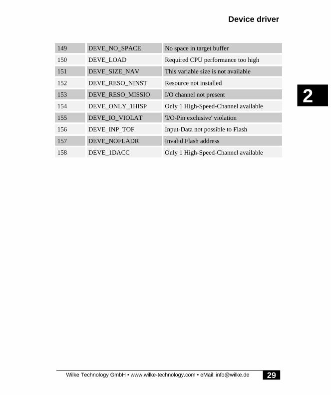
Device driver
Wilke Technology GmbH • www.wilke-technology.com • eMail: [email protected]
2
29
149 DEVE_NO_SPACE No space in target buffer
150 DEVE_LOAD Required CPU performance too high
151 DEVE_SIZE_NAV This variable size is not available
152 DEVE_RESO_NINST Resource not installed
153 DEVE_RESO_MISSIO I/O channel not present
154 DEVE_ONLY_1HISP Only 1 High-Speed-Channel available
155 DEVE_IO_VIOLAT 'I/O-Pin exclusive' violation
156 DEVE_INP_TOF Input-Data not possible to Flash
157 DEVE_NOFLADR Invalid Flash address
158 DEVE_1DACC Only 1 High-Speed-Channel available

Device driver
Wilke Technology GmbH • www.wilke-technology.com • eMail: [email protected]
2
30
Empty Page

A/D-Inputs with Analog1
Wilke Technology GmbH • www.wilke-technology.com • eMail: [email protected]
2
31
A/D-Inputs with Analog1The device driver ‘ANALOG1’ reads the instantaneous value of the analog inputs.
File name: ANALOG1.TDD
INSTALL DEVICE #D, "ANALOG1.TDD"
D is a constant, variable or expression of the data type BYTE,WORD, LONG in the range from 0→63 and stands for thedevice number of the driver.
The device driver ANALOG1.TDD reads the 4 internal analog inputs. Theinstantaneous values are read. The secondary addresses, 0 to 3, correspond to the 4input channels. All 4 channels can be read at once with 8 bit resolution, usingsecondary address 4. Only one variable is specified. The 4 bytes are read into a stringor a LONG value.
The resolution is 8 bits if BYTEs are read (e.g.: GET #n,#sa,1,CHAR) or 10 Bit ifWORD or LONG values are read.
The resolution can be improved and the noise "calculated out" with the aid of theFIFO buffer and the command INTEGRAL_FIFO.
Examples:
GET #4,#0,1,Value reads 1 byte from A/D-channel 0 via analog1-driver, channel 4.This 1 byte is assigned to Value (8-Bit resolution). Value is ofthe type LONG, WORD or BYTE:
GET #4,#3,2,Value reads 2 bytes from A/D-channel 3 via analog1-driver. These 2bytes are assigned to Value (10-Bit resolution). Value is of thetype LONG or WORD:
GET #4,#4,4,Value reads 1 byte from each A/D-channel, 0 to 3, via analog1-driver.These 4 bytes are assigned to Value (4 x 8-Bit resolution).Value is of the type LONG. The byte from channel 0 is theleast significant byte.
GET #4,#5,8,W$ reads 4 channels using 10-bits for each. The values can beoutput, in several configurations. As an example:Using analog1 driver to access A/D channels 0 to 3, 2 bytes areused for each channel, to allow 10 bit resolution, and assigned

Device driver
Wilke Technology GmbH • www.wilke-technology.com • eMail: [email protected]
2
32
to W$. W$ must be a string to accept 4 x 2 bytes. The lowerorder byte of channel 1 is the least significant byte of W$.The function NFROMS (Number from String) reads the bytesin their correct form out of the string.
The sample code below shows a combination of reading 4 analog channels andprinting the value of one channel to an output device.
GET #4,#5,8,W$PRINT #1, NFROMS ( W$, 0, 2 ) ‘ output value of channel 0
Program example:
'--------------------------------------------------------------------'Name: ANALOG1.TIG'--------------------------------------------------------------------TASK Main 'begin task MAIN ARRAY Value(4) OF LONG 'array of type LONG LONG K 'var of type LONG'install LCD-driver (BASIC-Tiger) INSTALL DEVICE #1, "LCD1.TDD"'install LCD-driver (TINY-Tiger)' INSTALL DEVICE #1, "LCD1.TDD", 0, 0, 0, 0, 0, 0, 80h, 8 INSTALL DEVICE #4, "ANALOG1.TDD" 'install ADC-driver
FOR EVER = 0 TO 0 STEP 0 'endless loop FOR K = 0 TO 3 '4 channels GET #4, #K, 2, Value(K) 'get value from ADC NEXT 'next channel PRINT #1, "<1>"; 'clear screen FOR K = 0 TO 3 '4 channels PRINT #1, "AD"; K; ":"; 'show channel no. PRINT #1, Value(K) 'show value NEXT 'next channel WAIT_DURATION 100 'wait 100 ms NEXTEND 'end task MAIN

A/D-Inputs with Analog2
Wilke Technology GmbH • www.wilke-technology.com • eMail: [email protected]
2
33
A/D-Inputs with Analog2The device driver ‘ANALOG2’ samples the analog value and stores the recovereddata into a FIFO buffer. The data sampling rate is controlled by the time base devicedriver, TIMERA.
Further information on ANALOG2.TDD:
• User-Function-Codes ANALOG2.TDD• Measuring into FIFO• Measuring into a String variable• Measuring with 12-bit resolution• Set sample rate
File name: ANALOG2.TDD
INSTALL DEVICE #D, "ANALOG2.TDD"
D is a constant, variable or expression of the data type BYTE,WORD, LONG in the range from 0→63 and stands for thedevice number of the drivers.
The Device Driver ANALOG2.TDD reads analog measured values and transfers theminto a FIFO buffer or a STRING variable. Analog reading operations aresynchronized using driver ‘TIMERA.TDD’, yielding a high performance independentof the BASIC program. The TIMER driver provides a reference frequency, which isdivided by the ANALOG2’s pre-scaler to yield the actual sample rate. The driver isconfigured using User Function Codes, UFC. Subsequent changes can be made in thesame way.
ANALOG2 supports resolutions of 8-Bit, 10-Bit, and 12-Bit-interpolated. The analogvalues are read into a string or into a FIFO buffer. The following modes of driveroperation are supported to read data ;
• from one channel of your choice• from channel 0 and 1• from channel 0, 1 and 2• from channel 0, 1, 2, and 3
As a result there are many configurations for the employment of the driver, i.e. whichchannels are to be used, at what resolution and to which type of buffer the recovereddata is to be transferred. Furthermore, the choice of sampling rate to be used can be

Device driver
Wilke Technology GmbH • www.wilke-technology.com • eMail: [email protected]
2
34
influenced in different ways. Some options determine the driver's behavior, regardingthe use of STRING and FIFO type buffers. The following paragraphs will show thedifference between ‘Measure into String’ and ‘Measure into FIFO’ and what must beobserved in the use of a variety of configurations.
The analog system is configured by User Function Codes, which are defined assymbols in the include file UFUNCn.INC. Once the driver has been configured, itneedn't be reconfigured before each new measurement. Within the command thatinvokes the driver, some configuration parameters can be given explicitly, i.e. offsetwithin a string, the number of measurements. This configuration is only valid for thismeasurement. The configuration set by the use of User Function Codes remainsunaffected.
The following table shows an overview of the ANALOG2 driver special FunctionCodes . The file, UFUNCx.INC, must be included in a program using the driver sothat the compiler will be aware of used symbol names.

A/D-Inputs with Analog2
Wilke Technology GmbH • www.wilke-technology.com • eMail: [email protected]
2
35
User-Function-Codes ANALOG2.TDDUser Function Codes of ANALOG2.TDD to set parameters (PUT):
No SymbolPrefix: UFCO_
Description
128 UFCO_AD2_CHAN set single channel mode (FIFO, STRING):0, 1, 2, 3The channel set will also be the channel used inthe multiple channel mode, when only onechannel is used.
129 UFCO_AD2_RESO Set resolution (FIFO, STRING):8 = 8-Bit10 = 10-Bit12 = 12-Bit
130 UFCO_AD2_INTEG Integration width at 12-Bit (FIFO, STRING):16, 32, 64, or 128
132 UFCO_AD2_ANZ No. of measurements (per channel) (FIFO)0 = endless (FIFO only)n = no. of measurements (LONG)
133 UFCO_AD2_PSCAL The pre-scaler, which divides the referencefrequency of "TIMERA.TDD" (for both FIFO& STRING usage):0,1 = no pre-scalern = divider (WORD)
134 UFCO_AD2_STOP Stop AD-Sampling (FIFO, STRING):parameter is only dummy
135 UFCO_AD2_GROF Set string size adjustment-flag (STRING)0 = spontaneous assignment of string size at endof each measurement process.else = dynamic adjustment of string size duringmeasurement process, if required.
136 UFCO_AD2_SCAN Set multiple channels mode and no. of channelsused (FIFO, STRING):1, 2, 3 or 4 channelsn = 1: channel set by UFC_AD2_CHANn = 2: 2-Channels: Ch-0, Ch-1n = 3: 3-Channels: Ch-0, Ch-1, Ch-2
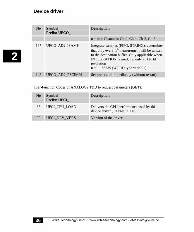
Device driver
Wilke Technology GmbH • www.wilke-technology.com • eMail: [email protected]
2
36
No SymbolPrefix: UFCO_
Description
n = 4: 4-Channels: Ch-0, Ch-1, Ch-2, Ch-3
137 UFCO_AD2_ISAMP Integrate-samples (FIFO, STRING): determinesthat only every nth measurement will be writtento the destination buffer. Only applicable whenINTEGRATION is used, i.e. only at 12-Bitresolutionn = 1...65535 (WORD type variable)
143 UFCO_AD2_PSCIMM Set pre-scaler immediately (without restart)
User-Function Codes of ANALOG2.TDD to request parameters (GET):
No SymbolPrefix: UFCI_
Description
68 UFCI_CPU_LOAD Delivers the CPU performance used by thisdevice driver (100%=10.000)
99 UFCI_DEV_VERS Version of the driver
A/D-Inputs with Analog2
Wilke Technology GmbH • www.wilke-technology.com • eMail: [email protected]
2
37
Measuring into FIFOFirst set the resolution, the (maximum) measuring rate, and the number of channels tobe used.
If you want to generate an un-interrupted flow of measured data, then a FIFO buffer isto be used for the measurement. The speed of the subsequent data processingdetermines the maximum possible measuring rate that can be used to prevent the riskof FIFO overflows and data corruption.. Speed of subsequent buffer data processing isrelated to the size of the FIFO buffer used. Larger buffers allow larger speedvariations. However, transferring data into a FIFO buffer and recovering data from theFIFO buffer is slower than capturing into a string.
Note that when the FIFO buffer is full then the device driver will cease measuring.The process must be restarted to make further measurements.
With a 12-bit resolution, the integration depth can be chosen, i.e. the size of internalintegration buffer. The number of measurements made can be reduced if not everymeasurement is transferred to your string or FIFO buffer. In such a way,measurements will be generated which are integrated but not close together in time,reducing the amount of data produced.
After using the User Function Codes to configure the driver, data transfer into a FIFObuffer will start:
PUT #D, FIFO_Name
D is a constant, variable or expression of type BYTE, WORD,LONG in the range from 0 to 63 and acts as the driver‘s devicenumber.
FIFO_Name is the name of the FIFO buffer capturing the analog data. Thebuffer is a FIFO using Byte variables when measuring with an8-bit resolution and Word variables for 10- or 12-Bitmeasurement resolution. The FIFO buffer is set to empty onstart-up.
NOTE: values produced by the integrating action under 12-bit resolution are onlyvalid after the FIFO buffer has been completely filled.
Data processing can be stopped by the User Function Code:
UFCO_AD2_STOP.

Device driver
Wilke Technology GmbH • www.wilke-technology.com • eMail: [email protected]
2
38
Program example:
'--------------------------------------------------------------------'Name: ANALOG2F.TIG'--------------------------------------------------------------------#INCLUDE DEFINE_A.INC 'general defines#INCLUDE UFUNC3.INC 'User Function Codes
TASK MAIN 'begin task MAIN FIFO SAMPLE (256) OF WORD 'Sample-buffer WORD A, B, C, D 'var. for analog values'install LCD-driver (BASIC-Tiger) INSTALL DEVICE #LCD, "LCD1.TDD"'install LCD-driver (TINY-Tiger)'INSTALL DEVICE #LCD, "LCD1.TDD", 0, 0, 0, 0, 0, 0, 80h, 8'install TIMER-A driver (time-base timer: 1001Hz) INSTALL_DEVICE #TA, "TIMERA.TDD", 3, 156'install ANALOG-2 driver INSTALL_DEVICE #AD2, "ANALOG2.TDD"
PUT #AD2,#0,#UFCO_AD2_RESO, 10 'resolution PUT #AD2,#0,#UFCO_AD2_SCAN, 4 'no. of channels PUT #AD2,#0,#UFCO_AD2_STOVL, 0 'stop on overflow PUT #AD2,#0,#UFCO_AD2_PSCAL, 5 'prescaler: 1001/5=200S/sec PUT #AD2,SAMPLE 'start measurement
K = 0 WHILE K < 127 'end when FIFO is full K = LEN_FIFO(SAMPLE) PRINT #LCD, "<1>Length=";K ENDWHILE '---------------------------- WHILE LEN_FIFO(SAMPLE) > 4 'show FIFO GET_FIFO SAMPLE, A PRINT #LCD, "<1bh>A<12><0><0f0h>";A; GET_FIFO SAMPLE, B PRINT #LCD, "<1bh>A<12><1><0f0h>";B; GET_FIFO SAMPLE, C PRINT #LCD, "<1bh>A<12><2><0f0h>";C; GET_FIFO SAMPLE, D PRINT #LCD, "<1bh>A<12><3><0f0h>";D; ENDWHILE PRINT #LCD, "<1Bh>A<0><3><0F0h>ready";END 'end task MAIN
A/D-Inputs with Analog2
Wilke Technology GmbH • www.wilke-technology.com • eMail: [email protected]
2
39
Measuring into a String variableFirst choose the resolution, the (maximum) measuring rate, and the number ofchannels to be used. (see the example command below)
If you want to generate sectioned measurements you should measure into a string.Advantages: measuring into a string needs less CPU resources and string dataprocessing is faster than FIFO data processing . For example, if the data should besent on a serial channel then the string could immediately be sent in segments of 240bytes. This is the limit of the instructions PRINT and PUT. Measurement willautomatically be stopped when the string is full.
First, declare a string of the size required. Then install the time base driver,TIMERA.TDD, and set it to the highest frequency required in the application.Configure the pre-scaler, resolution, number of channels and number ofmeasurements.
The output-string must exist at all times ! Transient variables (e.g. local strings usedin sub-routines or temporary strings (expressions) must NOT be used. Globalstrings or strings local to the relevant Task must be used.
Any measurements made do not have to be inserted from the string position 0. Anoffset can be declared to determine from which point within the string newmeasurements can be written. The string variable needn't be empty. Any data storedprior to this offset starting position will NOT be affected. If the offset goes beyond theend of the string variable, undefined values will be stored in the string positions priorto the offset.
The measurement process will be terminated when the predefined number ofmeasurements has been taken or when the string is full. However, the string datamight not reach the maximum length. As an example, when after measuring with 4channels at a resolution of 8-bits there may be 2 bytes left in the string. These 2 byteswill remain undefined, as one measurement produces 4 bytes.
After configuration with User Function Codes, data transfer into a STRING will start:
PUT #D, String [, Position, Number, Growth_Flag ]
D is a constant, variable or expression of the type BYTE, WORD,LONG in the range from 0 to 63 and acts as the driver’s devicenumber.
�

Device driver
Wilke Technology GmbH • www.wilke-technology.com • eMail: [email protected]
2
40
String is the name of the string capturing the analog data.The string must exist at all times, global or task-local.Note: the string is not set to empty.
Position is a variable, constant or expression of the type BYTE, WORDor LONG and specifies the start position in the string.Default = 0.
Number is a variable, constant or expression of the type BYTE, WORDor LONG and specifies the number of measurements.Measuring on more than one channel will produce more bytesper measurement. Measurements with a resolution of 12 bit or10 bit generate 2 bytes per channel and per measurement.Number= 0: measurement will run until the string is full.
Growth_Flag is a variable, constant or expression of the type BYTE, WORDor LONG and determines if the size of the string growsgradually or if the string size is set at once after themeasurement has been finished:0: string grows gradually.<> 0: string size set after the measurement has been finished.
When the offset, number of measurements, or growth_flag parameters are not given,then the configuration set by the User Function Codes will be used. When offset,number of measurements, or growth_flag are given then these settings are only activefor this measurement and do not change the configuration set by the User FunctionCodes.
If the string becomes full before the requested number of measurements have beenmade, then the process is stopped regardless. This may produce undefined values atthe end of the string. As an example, if 8 bytes per measurement are required, i.e. 4channels at 10-bit resolution, and the string is not a multiple of 8, the last reading willbe corrupted.
The measurement can be stopped by using the User Function Code
UFCO_AD2_STOP.
A/D-Inputs with Analog2
Wilke Technology GmbH • www.wilke-technology.com • eMail: [email protected]
2
41
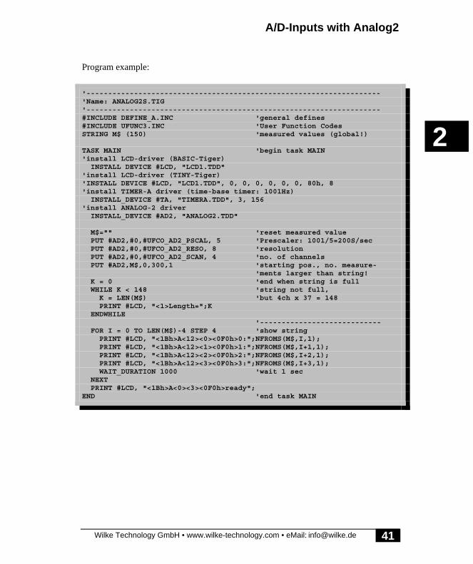
Program example:
'--------------------------------------------------------------------'Name: ANALOG2S.TIG'--------------------------------------------------------------------#INCLUDE DEFINE_A.INC 'general defines#INCLUDE UFUNC3.INC 'User Function CodesSTRING M$ (150) 'measured values (global!)
TASK MAIN 'begin task MAIN'install LCD-driver (BASIC-Tiger) INSTALL DEVICE #LCD, "LCD1.TDD"'install LCD-driver (TINY-Tiger)'INSTALL DEVICE #LCD, "LCD1.TDD", 0, 0, 0, 0, 0, 0, 80h, 8'install TIMER-A driver (time-base timer: 1001Hz) INSTALL_DEVICE #TA, "TIMERA.TDD", 3, 156'install ANALOG-2 driver INSTALL_DEVICE #AD2, "ANALOG2.TDD"
M$="" 'reset measured value PUT #AD2,#0,#UFCO_AD2_PSCAL, 5 'Prescaler: 1001/5=200S/sec PUT #AD2,#0,#UFCO_AD2_RESO, 8 'resolution PUT #AD2,#0,#UFCO_AD2_SCAN, 4 'no. of channels PUT #AD2,M$,0,300,1 'starting pos., no. measure- 'ments larger than string! K = 0 'end when string is full WHILE K < 148 'string not full, K = LEN(M$) 'but 4ch x 37 = 148 PRINT #LCD, "<1>Length=";K ENDWHILE '---------------------------- FOR I = 0 TO LEN(M$)-4 STEP 4 'show string PRINT #LCD, "<1Bh>A<12><0><0F0h>0:";NFROMS(M$,I,1); PRINT #LCD, "<1Bh>A<12><1><0F0h>1:";NFROMS(M$,I+1,1); PRINT #LCD, "<1Bh>A<12><2><0F0h>2:";NFROMS(M$,I+2,1); PRINT #LCD, "<1Bh>A<12><3><0F0h>3:";NFROMS(M$,I+3,1); WAIT_DURATION 1000 'wait 1 sec NEXT PRINT #LCD, "<1Bh>A<0><3><0F0h>ready";END 'end task MAIN

Device driver
Wilke Technology GmbH • www.wilke-technology.com • eMail: [email protected]
2
42
Measuring with 12-bit resolutionAt a resolution of 12 bits an integration buffer is used in order to calculate a higherresolution than the 10 bit the hardware delivers. The integration depth (size of theinternal integration buffer) can be adjusted. The measured values are correct after theintegration buffer has been filled.
The number of measurements made can be reduced by transferring only every nth
value into the string or FIFO buffer. Integrated measurements are generated at a lowersample rate, using this method.
PUT #7, #0, #UFCO_AD2_RESO, 12 ‘ set 12 bit resolutionPUT #7, #0, #UFCO_AD2_INTEG, 32 ‘ set 32 bit integration bufferPUT #7, #0, #UFCO_AD2_ISAMP, 64 ‘ only every 9th measurement taken ‘ this divides sample rate by 9
The accuracy of integrated values improves with the size of the integration bufferused, i.e. bigger array gives higher accuracy. However, the inherent low- pass filtereffect of an integrator will remove the higher frequency components from therecorded signal spectrum.
The following condition must be met when using the 12 bit resolution for singlemeasurements: the value set with UFCO_AD2_ISAMP must be bigger or equal theintegration buffer size set with UFCO_AD2_INTEG. (Example: 4-channel volt meterANA2_4XV.TIG in the subdirectory APPLICAT)
�

A/D-Inputs with Analog2
Wilke Technology GmbH • www.wilke-technology.com • eMail: [email protected]
2
43
Set sample rateThe sample rate will be derived from the base frequency supplied by theTIMERA.TDD device driver. The pre-scaler of the device driver, ANALOG2.TDD,converts the driver’s base frequency to the required sample rate:
You will find further information concerning the device driver TIMERA.TDD onpages 365 and following pages. The pre-scaler is set by using the User Function Code,UFCO_AD2_PSCAL. For an example, please see ‘Measuring into FIFO’ and‘Measuring into a String’.
When using high sampling speeds, this device-driver together in combination withdriver TIMERA.TDD can place such a demand on CPU resources that other taskswithin a program may be affected. The load placed onto the CPU by this driver can bedetermined by using the User-Function-Code, ‘UFCI_CPU_LOAD.Certain values that would result in system-overload, will not be accepted by thedriver.NOTE: TIMERA.TDD must be installed prior to installing ANALOG2.TDD.
�
pre-scalerof
devicedriver
range 1
divisionfactor
xxMHzrange 2
range 3
TIMERA otherdevice driver
range clock

A/D inputs with Analog3
Wilke Technology GmbH • www.wilke-technology.com • eMail: [email protected]
2
45
A/D inputs with Analog3The device driver ‘ANALOG3’ reads in analog values from the external A/D-moduleEP11.
Further information on ANALOG3.TDD:
• Secondary addresses of the ANALOG3.TDD• User-Function-Codes of the ANALOG3.TDD• Scale measurement range• Adjust input voltage range• Define channel groups• Delete channel group• Read A/D-value and read from a channel group
File name: ANALOG3.TDD
INSTALL DEVICE #D, "ANALOG3.TDD", P1,..., P11
D is a constant, variable or expression of the data type BYTE,WORD, LONG in the range 0...63 and stands for the devicenumber of the driver.
P1...P11 are further parameters which determine the connection of theEP11-module to BASIC-Tiger®. These parameters aredescribed in the following table.
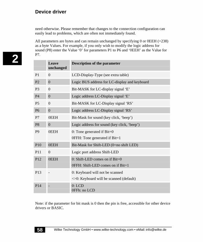
All parameters are bytes and can leave the standard value unchanged by specifying 0or 0EEH (=238).

Device driver
Wilke Technology GmbH • www.wilke-technology.com • eMail: [email protected]
2
46
Standard
leaveunchang
ed
Description of parameter
P1 6 0 Logical BUS address for EP11
P2 8 0 Logical port address for: -RD, -WR, HBEN, -CE
P3 0 0eeh Bit number for Signal ‘-RD’
P4 1 0eeh Bit number for signal ‘-WR’
P5 3 0eeh Bit number for signal ‘-HBEN’
P6 5 0eeh Bit number for signal ‘-CE’
P7 1 0eeh I/O Access-Speed-Reduction (1=no,2...32)
P8 0 0eeh Always 0, reserved parameter
P9 0 0eeh 0 = no address signals used1 = an address line for 2 A/D ports2 = two address lines for 4 A/D ports3 = three address lines for 8 A/D-Ports
P10 7 0 Logical port address for address signals from EP11
P11 0 0eeh First bit-position for address signals (0...7)e.g. two address signals at port 8, first position 6:L86 and L87 are address signals
I/O Access-Speed-Reduction is set to '1' with the combination BASIC-Tiger® A,Tiny-Tiger® in combination with the module EP11, i.e. without speed reduction. Adifferent value may be necessary if compatible A/D-modules come onto the marketwhich convert more slowly or if faster BASIC-Tiger® modules become available.
The control lines may partly be used together with other device drivers, particularlywith the control lines of the graphic LCD.
The device driver ANALOG3.TDD reads in analog measured values from theexternal analog channels of the analog extension module EP1. The measurements arethen executed with the GET instruction and the results then read.

A/D inputs with Analog3
Wilke Technology GmbH • www.wilke-technology.com • eMail: [email protected]
2
47
The resolution is 12 bit. The driver supports the different modes of the A/D inputs ofthe EP11 module:
• Input voltage 0...5V• Input voltage -5V...+ 5V• Input voltage 0...10V• Input voltage -10V...+ ..+10V
Two different read modes are available:
• from a random channel• from a channel group compiled beforehand
The channel modes are set and the groups compiled before the measurement. Themeasurement is then executed initiated with the GET instruction and the results readin directly.
The settings for the analog measuring system are carried out by an output of strings tocertain secondary addresses. Settings which have been made once are retained and donot have to be repeated before each measurement.
The following table shows an overview of the special functions of the driver on thesecondary address.
Secondary addresses of the ANALOG3.TDDSecondary address Description
0...63 PUT: Set the input voltage rangesfor channels 0 to 63
GET: Read from a single channel
64...71 PUT: Define channel groups (8 groups are possible)
GET: Read from channel group of all defined channels

Device driver
Wilke Technology GmbH • www.wilke-technology.com • eMail: [email protected]
2
48
User-Function-Codes of the ANALOG3.TDDUser-Function-Codes of the ANALOG3.TDD to set parameters (PUT):
No SymbolPrefix: UFCO_
Description
144 UFCO_AD3_FACTOR Sets the value which is delivered with amaximum A/D measured value of thecorresponding channel (WORD).4096 corresponds to factor 1
Scale measurement rangeA value can be set which is then used to scale the measured value with the User-Function-code UFCO_AD3_FACTOR. The scaling factor can be set individually forevery channel by writing to the secondary address of the channel. If several values arewritten to a secondary address the factors will be issued as of the secondary addressand for the following addresses. After a Reset the values are set to the factor 1,corresponding to the factor value 4096.
The A/D- converter delivers as maximum value 4095. The following calculation iscarried out with the factor:
Measurement result = (measurement * factor + 2048) / 4096
2048 are added after multiplication for rounding off. A factor value of e.g. 100 leadsto the following calculation at a maximum value of the A/D converter:
Measurement result = (4095 * 100 + + 2048) / 4096
leading to a measurement result of 100. The factor value thus also specifies thedesired value for end scale deflection.

A/D inputs with Analog3
Wilke Technology GmbH • www.wilke-technology.com • eMail: [email protected]
2
49
Program example:
'--------------------------------------------------------------------'Name: ANA3_8XV.TIG'--------------------------------------------------------------------TASK Main 'begin task MAIN BYTE EVER, K REAL V, W ARRAY Value(8) OF WORD 'array of type WORD
DIR_PORT 8,0
'install LCD-driver (BASIC-Tiger) INSTALL DEVICE #1, "LCD1.TDD"'install LCD-driver (TINY-Tiger)'INSTALL DEVICE #1, "LCD1.TDD", 0, 0, 0, 0, 0, 0, 80h, 8 INSTALL DEVICE #4, "ANALOG3.TDD", & 'install ADC-driver 6, & 'port for data bus = default 8, & 'port for ctrl lines = default 3, & 'pin number for -RD = default 4, & 'pin number for -WR = default 5, & 'pin number for HBEN = default 7, & 'pin number for -CE = default 22, & 'speed reduction = default (no) 0, & 'reserved parameter always 0 3, & 'no. of address lines = default 8, & 'port for address lines = default 0 & 'bit position of address lines = default
PRINT #1,"EP11_001 - Test" PUT #4, #0, "00 00 00 00 00 00 00 00"% 'ch0...7: all 0...5V 'set factors for 4 channels SET_LEN$ ( FACTOR$, 8 ) 'init string 4for 4 WORDs F4 = 100 'factor for channel 4 FACTOR$ = NTOS$( FACTOR$, 0, 2, F4 ) 'insert into string F5 = 2550 'factor for channel 5 FACTOR$ = NTOS$( FACTOR$, 0, 2, F5 ) 'insert into string F6 = 10000 'factor for channel 6 FACTOR$ = NTOS$( FACTOR$, 0, 2, F6 ) 'insert into string F7 = 2550 'factor for channel 7 FACTOR$ = NTOS$( FACTOR$, 0, 2, F7 ) 'insert into string PUT #4, #4, FACTOR$ 'set factor f. channels 4,5,6,7
FOR EVER = 0 TO 0 STEP 0 'endless loop FOR K = 0 TO 7 '8 channels GET #4, #K, 2, VALUE(K) 'read value from ADC NEXT 'next channel PRINT #1, "<1>"; 'clear screen FOR K = 0 TO 7 STEP 2 'show 8 channels V = (LTR(Value(K))/4096.0 * 5000.0)/1000.0 USING "UD<1><1> 0.0.0.0.1" PRINT_USING #1, K;":"; 'channel no. + value USING "NF<1><1> <3> 0 0 0 0 0 0 0 1.3 0 0 0 0 0 0 0"

Device driver
Wilke Technology GmbH • www.wilke-technology.com • eMail: [email protected]
2
50
PRINT_USING #1, V; 'channel no. + value V = (LTR(Value(K+1))/4096.0 * 5000.0)/1000.0 USING "UD<1><1> 0.0.0.0.1" PRINT_USING #1, " ";K+1;":"; 'channel no. + value USING "NF<1><1> <3> 0 0 0 0 0 0 0 1.3 0 0 0 0 0 0 0" PRINT_USING #1, V 'channel no. + value
NEXT 'next channel WAIT_DURATION 100 'wait 100 ms NEXTEND 'end task MAIN

A/D inputs with Analog3
Wilke Technology GmbH • www.wilke-technology.com • eMail: [email protected]
2
51
Adjust input voltage rangeAn input voltage range for the A/D converter can be set at the extension module EP11for every channel. The desired area is coded in the lower two bits of a byte. A byte istransferred to the device driver with PUT for every channel to be set. The first channelto be set is selected by writing to a certain secondary address. The following bytes areused accordingly to the following channels. The table shows the coding for the areas:
Binary coding HEX coding Input voltage range
00000000b 0 unipolar 0V...+5V
00000001b 1 bipolar –5V...+5V
00000010b 2 unipolar 0V...+10V
00000011b 3 bipolar –10V...+10VV
The following example sets the input voltage range of the channels 17 to 22:
'...' +---------------------- Kanal 17: 0V... +5V' ! +------------------- Kanal 18: 0V...+10V' ! ! +---------------- Kanal 19: -5V... +5V' ! ! ! +------------- Kanal 20: -10V...+10V' ! ! ! ! +---------- Kanal 21: -10V...+10V' ! ! ! ! ! +--------Kanal 22: -5V... +5VPUT #AD3, #17, "00 02 01 03 03 01"%'...

Device driver
Wilke Technology GmbH • www.wilke-technology.com • eMail: [email protected]
2
52
Define channel groupsIf certain A/D channels are read more often and other channels only rarely, channelgroups can be formed to compile the reading of certain channels. The device driverANALOG3.TDD supports up to 8 groups. Each group can contain up to 64 channels.The groups are defined by an output of strings with the instruction PUT to thesecondary addresses 64...71.
Secondary address Channel group
64 Channel group 0
65 Channel group 1
66 Channel group 2
67 Channel group 3
68 Channel group 4
69 Channel group 5
70 Channel group 6
71 Channel group 7
The output strings contain the channel numbers. Channel numbers outside the validrange will be ignored. Channel may be freely compiled into a group. Double usage aswell as overlapping with other groups is also allowed. The channels will later be readin the order in which they have been defined. A group can be recompiled at any timeby simple resetting it.
...PUT #AD3, #71, "3F 00 01 2B 03"% ' channelgroup 7: 5 channelsPUT #AD3, #65, "<0><1><29><17>" ' channelgroup 1: 4 channelsPUT #AD3, #66, FILL$(64,"<4>") ' channelgroup 2: 64 channels...
Delete channel groupTo delete a group, set a channel outside the range of values, e.g. channel 99.
PUT #AD3, #64, "<99>" ' group 0: empty

A/D inputs with Analog3
Wilke Technology GmbH • www.wilke-technology.com • eMail: [email protected]
2
53
Read A/D-value singly and from a channel groupAn A/D value is read from a channel by simply reading from the correspondingsecondary address. Since the resolution is 12 bit, a WORD (2 bytes) will be neededfor every analog value.
GET #AD3, #10, 2, wVar ' reads value from channel 10
Reading with the instruction GET on the secondary addresses 64 to 71 reads allchannels in this group, though the maximum number of bytes that the variable cancontain. The channels will be read in the order in which they have been definedbeforehand in the group.

Device driver
Wilke Technology GmbH • www.wilke-technology.com • eMail: [email protected]
2
54
Program example:
'--------------------------------------------------------------------'Name: ANALOG3.TIG'sets EP11 channel 0...7 to range 0...5V'groups channels 0...7, reads, and displays the values'--------------------------------------------------------------------TASK Main 'begin task MAIN BYTE EVER 'for endless loop WORD W 'analog value REAL V 'value in Volt
DIR_PORT 8,0
'install LCD-driver (BASIC-Tiger) INSTALL DEVICE #1, "LCD1.TDD"'install LCD-driver (TINY-Tiger)'INSTALL DEVICE #1, "LCD1.TDD", 0, 0, 0, 0, 0, 0, 80h, 8 INSTALL DEVICE #4, "ANALOG3.TDD", & 'install ADC-driver 6, & 'port for data bus = default 8, & 'port for ctrl lines = default 3, & 'pin number for -RD = default 4, & 'pin number for -WR = default 5, & 'pin number for HBEN = default 7, & 'pin number for -CE = default 22, & 'speed reduction = default (no) 0, & 'reserved parameter always 0 3, & 'no. of address lines = default 8, & 'port for address lines = default 0 & 'bit position of address lines = default
PRINT #1,"EP11_001 - Test" PUT #4, #0, "00 00 00 00 00 00 00 00"% 'ch0...7: all 0...5V
FOR EVER = 0 TO 0 STEP 0 'endless loop GET #4, #0, 2, W 'read value from ADC V = (LTR(W)/4096.0 * 5000.0)/1000.0 'analog value in Volt USING "NF<1><1> <2> 0 0 0 0 0 0 0 1.2 0 0 0 0 0 0 0" PRINT_USING #1, "<1Bh>A<0><1><F0h>Analog:";V;"V"; WAIT_DURATION 100 'wait 100 ms NEXTEND 'end task MAIN
LCD panel and keyboard
Wilke Technology GmbH • www.wilke-technology.com • eMail: [email protected]
2
55
LCD panel and keyboardThis device driver supports three common units which normally are used together:
• LCD Panel that have the popular Hitachi-Controller HD44780, or acompatible unit. The display can be connected directly. Only a potentiometeris used for contrast adjustment, where necessary.
• LCD1 Keyboard with SHIFT and CTRL keys. The keyboard can have up to 128keys, where individual rows of the keyboard matrix can also be defined asDIP switches. External hardware on the keyboard daughterboard consists of afew low-cost HC-MOS-IC and keyboard matrix diodes. One example can befound in the circuit diagram of the Plug & Play Lab. A further exampleshowing a keyboard connected to the extended input pins is in the HardwareManual (Extended I/O system).
• Sound, acoustic signals such as BEEP, ALARM and key click's. Acorresponding output device is connected to pin L42 (Tiger A pin-No. 35) forthis purpose, e.g. the buzzer of the Plug & Play Labs.TINY Tiger® modules do not have the pin L42. This is the pin needed byLCD1 to operate the 'buzzer'. Extra parameters must be used when installingdevice driver, LCD1, to determine which pin is to be used with the driver.Most example programs contain the appropriate line containing theparameters for Tiny Tiger.
The description of LCD1 is subdivided into 3 parts LCD panel, keyboard, and sound.

Device driver
Wilke Technology GmbH • www.wilke-technology.com • eMail: [email protected]
2
56
ESC-CommandsCommands to the LCD1 device driver can also be sent with the normal data flow inPRINT or PUT instructions in the form of ESC sequences. The command sequencethen starts with <ESC> Code, followed by a command code and a different number ofparameters depending on the command. The sequence ends with an Eos code.
ESC: <1Bh>
EOS: <F0h>
Command codes are case sensitive!
<27> X p1, p2, p3, ...pn <F0h>
Eos code
Parameter n
Parameter 1
Command X
Esc code
The arguments in the following Esc commands (x, y, n) are always BYTES unlessotherwise specified. The commands are case sensitive. �

LCD Panel
Wilke Technology GmbH • www.wilke-technology.com • eMail: [email protected]
2
57
LCD PanelFurther information on LCD1.TDD, LCD panel:
• Type list• Connect LCD Panel• User-Function-Codes (LCD)• Control characters of the LC-display• ESC-Commands LC-display:• Position cursor: ESC A• Activate special character set: ESC S• Load special character set: ESC L• Reset special character set: ESC R• Menu on the LCD Panel: ESC M• Define cursor: ESC c• LCD Panel - Special character sets• Pre-defined special character sets
File name: LCD1.TDD
INSTALL DEVICE #D, "LCD1.TDD" [, LCD-Type, P2, ..., P14 ]
D is a constant, a variable or an expression of the data typeBYTE, WORD, LONG in the range from 0 to 63 and stands forthe device number of the driver.
LCD-Type specifies which type of LCD module is connected. In order touse the codes in the LCD type column of the following table,include the file UFUNCn.INC at the start of your program. Thelater the UFUNC-file version, the higher the n value inUFUNCn.INC.
P2...P14 are further parameters which modify the standard pinconfiguration of the LCD panel, the Keyboard 'Shift' LED, the'beep' audio output and key clicks. These parameters aredescribed at the end of LCD1 driver description section.Specification of a different LCD panel type alone, usually doesnot require the use of these parameters.
The device driver LCD1.TDD assumes that the components LCD panel, keyboard,Shift-LED and audio output are connected in the manner described in this chapter.You should always use the standard configuration unless special circuit requirements
Device driver
Wilke Technology GmbH • www.wilke-technology.com • eMail: [email protected]
2
58
need otherwise. Please remember that changes to the connection configuration caneasily lead to problems, which are often not immediately found.
All parameters are bytes and can remain unchanged by specifying 0 or 0EEH (=238)as a byte Values. For example, if you only wish to modify the logic address forsound (P8) enter the Value ‘0’ for parameters P1 to P6 and ‘0EEH’ as the Value forP7.
Leaveunchanged
Description of the parameter
P1 0 LCD-Display-Type (see extra table)
P2 0 Logic BUS address for LC-display and keyboard
P3 0 Bit-MASK for LC-display signal ‘E’
P4 0 Logic address LC-Display signal ‘E’
P5 0 Bit-MASK for LC-Display signal ‘RS’
P6 0 Logic address LC-Display signal ‘RS’
P7 0EEH Bit-Mask for sound (key click, ‘beep’)
P8 0 Logic address for sound (key click, ‘beep’)
P9 0EEH 0: Tone generated if Bit=0
0FFH: Tone generated if Bit=1
P10 0EEH Bit-Mask for Shift-LED (0=no shift LED)
P11 0 Logic port address Shift-LED
P12 0EEH 0: Shift-LED comes on if Bit=0
0FFH: Shift-LED comes on if Bit=1
P13 - 0: Keyboard will not be scanned
<>0: Keyboard will be scanned (default)
P14 - 0: LCD0FFh: no LCD
Note: if the parameter for bit mask is 0 then the pin is free, accessible for other devicedrivers or BASIC.

LCD Panel
Wilke Technology GmbH • www.wilke-technology.com • eMail: [email protected]
2
59
The specification of a different LCD panel type is normally sufficient fordevelopment work. When installing the LCD1 device driver, parameters can be usedto configure the port to control external components.
Type listIntegrate the newest include file ‘UFUNCn.INC’ to use the identifier for the LCDtype. Parameter ‘LCD-Type’:
No LCD-Type Lines x Columns Refresh-Mode
1 LCD1_1_8 1 x 8 1:8
2 LCD1_1_12 1 x 12 1:8
3 LCD1_1_16 1 x 16 1:8
4 LCD1_1_20 1 x 20 1:8
5 LCD1_1_40 1 x 40 1:8
6 LCD1_2_8 2 x 8 1:8
7 LCD1_2_12 2 x 12 1:8
8 LCD1_2_16 2 x 16 1:8
9 LCD1_2_20 2 x 20 1:8
10 LCD1_2_40 2 x 40 1:8
11 LCD1_4_20 4 x 20 1:8
12 LCD2_2_8 2 x 8 1:16
13 LCD2_2_12 2 x 12 1:16
14 LCD2_2_16 2 x 16 1:16
15 LCD2_2_20 2 x 20 1:16
16 LCD2_2_40 2 x 40 1:16
17 LCD2_4_20 4 x 20 (default) 1:16
18 LCD2_2_24 2 x 24 1:16
19 LCD2_4_16 4 x 16 1:16
20 LCDNJU_4_24 4 x 24

Device driver
Wilke Technology GmbH • www.wilke-technology.com • eMail: [email protected]
2
60
21 LCDNJU_1_16 1 x 16
22 LCDNJU_2_16 2 x 16
23 LCDNJU_2_24 2 x 24
24 LCDNJU_2_32 2 x 32
25 LCDNJU_2_40 2 x 40
26 LCDNJU_4_8 4 x 8
27 LCDNJU_4_16 4 x 16
28 LCDNJU_4_20 4 x 20
If no LCD type is specified, Type 17 is the default type used.
Examples:
Change the LCD panel type to a model with 2 lines of 40 characters (‘LCD1_2_40’ isdefined in the include file ‘DEFINE_A.INC’):
INSTALL_DEVICE “LCD1.TDD“, LCD1_2_40
Put the sound pin to L87. Leave the rest of the configuration unchanged:
INSTALL_DEVICE “LCD1.TDD“, 0, 0, 0, 0, 0, 0, 80h, 8
The device driver LCD1 can be installed more than one time, e.g. in order to connectmultiple LCDs or multiple keyboards. All devices will still use the same data bus, butdifferent control lines. The LCD as well as the keyboard can be disabled.
Disable keyboard scanning, but leave the rest of the configuration unchanged:
INSTALL_DEVICE “LCD1.TDD, 0,0,0,0,0,0,0eeh,0,0eeh,0eeh,0,0eeh,0
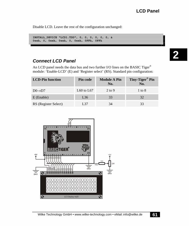
LCD Panel
Wilke Technology GmbH • www.wilke-technology.com • eMail: [email protected]
2
61
Disable LCD. Leave the rest of the configuration unchanged:
INSTALL_DEVICE “LCD1.TDD“, 0, 0, 0, 0, 0, 0, &0eeh, 0, 0eeh, 0eeh, 0, 0eeh, 0FFh, 0FFh
Connect LCD PanelAn LCD panel needs the data bus and two further I/O lines on the BASIC Tiger®
module: ‘Enable-LCD’ (E) and ‘Register select’ (RS). Standard pin configuration:
LCD-Pin function Pin code Module A PinNo.
Tiny-Tiger® PinNo.
D0→D7 L60 to L67 2 to 9 1 to 8
E (Enable) L36 33 32
RS (Register Select) L37 34 33

Device driver
Wilke Technology GmbH • www.wilke-technology.com • eMail: [email protected]
2
62
Since LCD panels have their own controller, they can crash or become unstableindependently of their controlling environment. This can occur due to staticdischarges in the vicinity of the LCD panel or data cable crosstalk. The latter occursparticularly in very long cables. Experience has shown that an appropriate groundconnection is critical when using long data cables. If the display does crash, onesolution is to reset the LCD panel from the controlling module sending the UFCcommand UFCO_LCD_RESET to the LCD1 device driver.
User-Function-Codes (LCD)User Function Codes of LCD1.TDD to request parameters (GET):
No SymbolPrefix UFCI_
Description
33 UFCI_OBU_FILL Number of bytes in output buffer (Byte)
34 UFCI_OBU_FREE Free space in output buffer (Byte)
35 UFCI_OBU_VOL Size of output buffer (Byte)
65 UFCI_LAST_ERRC Last error code
99 UFCI_DEV_VERS Driver version
User Function Codes of LCD1.TDD to set parameters (PUT):
No SymbolPrefix: UFCO_
Description
1 UFCO_IBU_ERASE Delete keyboard input buffer
33 UFCO_OBU_ERASE Delete LCD output buffer
176 UFCO_LCD_RESET reset LCD

LCD Panel
Wilke Technology GmbH • www.wilke-technology.com • eMail: [email protected]
2
63
Control characters of the LC-displayControl characters are written directly to the LCD device with no Esc and Eos.
CLR <01> deletes the LCD screen
HOME <02> sets the cursor in the top left corner
FS <05> Cursor 1 position to the right
BS <08> Cursor 1 position to the left
LF, DO <0Ah> Cursor 1 position down
UP <0Bh> Cursor 1 position up
FF <0Ch> Form Feed
CR <0Dh> Carriage Return
PRINT #LCD, “<1>“;
Deletes the LCD screen and moves the cursor to its ‘home’ position (X=0, Y=0). Thiscan be directly followed by text command:
PRINT #LCD, “<1>Hello World“

Device driver
Wilke Technology GmbH • www.wilke-technology.com • eMail: [email protected]
2
64
ESC-Commands LC-display:Overview:
ESC, A, x, y, EOS Absolute cursor addressing
ESC, S, n, EOS Activate special character set n
n=0→15
ESC, L, n, Data, EOS Load special character set n
n=0→15
64 Bytes Data Example: pg. 388
ESC, R, n, EOS Reset special character set n
if n>15: reset all
ESC, M, n, EOS Tz String Menu selection n
n is the index in the menu
Tz is the break character Example: pg. 73
ESC, c, n, EOS Define cursor
n=0: Cursor off
n=1: Cursor on
n>1: Cursor on + flash
ESC sequences must always be output in a PRINT or PUT instruction. If the linelength allows, a number of ESC sequences can be output in one instruction.

LCD Panel
Wilke Technology GmbH • www.wilke-technology.com • eMail: [email protected]
2
65
Position cursor: ESC APRINT #D, “<1Bh>A“; CHR$(x); CHR$(y); “<F0h>“;
This positions the display cursor using absolute reference values.
D is a constant, a variable or expression of the data type BYTE,WORD, LONG in the range from 0→63 and stands for thedevice number of the driver.
x x-coordinate (column), at which the cursor is to be positioned.
y y-coordinate (line), at which the cursor is to be positioned.
Column and row numbers start at 0. The possible value range depends on the LCDtype used. Entered values for x and y, which are too large are set 0.
A 4x20 LCD panel uses the following numbering system:
0 1 2 3 4 5 6 7 8 9 10 11 12 13 14 15 16 17 18 19
0
1
2
3

Device driver
Wilke Technology GmbH • www.wilke-technology.com • eMail: [email protected]
2
66
Program example:
'--------------------------------------------------------------------'Name: GOTOXY.TIG'--------------------------------------------------------------------'An asterisk ('*') moves over the LC-display from'left to right and back.'--------------------------------------------------------------------TASK MAIN 'begin task MAIN BYTE X 'var of type BYTE'install LCD-driver (BASIC-Tiger) INSTALL DEVICE #1, "LCD1.TDD"'install LCD-driver (TINY-Tiger)'INSTALL DEVICE #1, "LCD1.TDD", 0, 0, 0, 0, 0, 0, 80h, 8 PRINT #1, "<1Bh>c<0><F0h>"; 'disable cursor PRINT #1, "<1>"; 'clear screen LOOP 9999999 'many loops FOR X = 0 TO 19 'loop over all columns CALL STARXY (X,1) '"*" at line 1, column X NEXT 'next column FOR X = 18 TO 1 STEP -1 'loop over all columns CALL STARXY (X,1) '"*" at line 1, column X NEXT 'next column ENDLOOPEND 'end task MAIN
'--------------------------------------------------------------------'Sub: cursor at position (x, y), print "*" and delete after 200ms'--------------------------------------------------------------------SUB STARXY (BYTE X,Y) 'begin subroutine STARXY PRINT #1, "<1Bh>A"; CHR$(X);& 'output "*" at position CHR$(Y); "<F0h>*"; 'line X, column Y WAIT DURATION 200 'wait 200 ms PRINT #1, "<1Bh>A"; CHR$(X);& 'output "*" at position CHR$(Y); "<F0h> "; 'line X, column YEND 'end subroutine STARXY

LCD Panel
Wilke Technology GmbH • www.wilke-technology.com • eMail: [email protected]
2
67
Activate special character set: ESC SPRINT #D, “<1BH>S“; CHR$(n); “<F0H>“;
Activates a special character set.
D is a constant, a variable or expression of the data type BYTE,WORD, LONG in the range from 0→63 and stands for thedevice number of the drivers.
n Number of the special character set (between 0 and 15).
There are 16 special character sets, of which only one can ever be active at one time.This determines the appearance of the 8 special characters available to be displayed.This means that all visible special characters must always be from the same specialcharacter set.
Characters from other special character sets, which are currently on display, areimmediately converted to the appropriate new character set.

Device driver
Wilke Technology GmbH • www.wilke-technology.com • eMail: [email protected]
2
68
Program example:
'--------------------------------------------------------------------'Name: SELECT_FONT.TIG'--------------------------------------------------------------------'repeats displaying all 16 special character sets one-by-one'for 2 seconds each.'--------------------------------------------------------------------TASK MAIN 'begin task MAIN BYTE X 'var of type BYTE'install LCD-driver (BASIC-Tiger) INSTALL DEVICE #1, "LCD1.TDD"'install LCD-driver (TINY-Tiger)'INSTALL DEVICE #1, "LCD1.TDD", 0, 0, 0, 0, 0, 0, 80h, 8 PRINT #1, "<1Bh>c<0><F0h>"; 'set cursor off PRINT #1, "<1>"; 'clear screen FOR X=0 TO 7 'loop over all chars PRINT #1, CHR$(80h + X); "-"; 'output of char NEXT 'next char LOOP 9999999 'many loops FOR X=0 TO 15 'loop over all fonts PRINT #1,"<1Bh>S";CHR$(X);"<F0h>";'activate font no. X WAIT DURATION 2000 'wait 2 sec NEXT 'next font ENDLOOPEND 'end task MAIN
Further details of the special characters of the LC-display can be found on pages 63f.

LCD Panel
Wilke Technology GmbH • www.wilke-technology.com • eMail: [email protected]
2
69
Load special character set: ESC LPRINT #D, “<1BH>L“; CHR$(n); Data record; “<F0H>“;
Defines or loads a special character set with configuration data.
D is a constant, a variable or expression of the data type BYTE,WORD, LONG in the range from 0→63 and stands for thedevice number of the drivers.
n Number of the special character set (between 0 and 15).
Data record 64 Bytes, which determines the font structure.
This ESC sequence loads your own special character set. Individual special charactersets are required if a custom symbol has to be shown, or if the standard character setdoes not provide certain foreign language characters, i.e. ß or Σ. The special characterset is transferred to the LCD and stored there. The character set has to be re-loadedafter every power up.

Device driver
Wilke Technology GmbH • www.wilke-technology.com • eMail: [email protected]
2
70
Program example:
'--------------------------------------------------------------------'Name: LOAD_FNT.TIG'--------------------------------------------------------------------'All characters of special character set 7 are shown on the'display. In a loop this special character set is loaded with'user defined characters and then set back to the standard'special character set every 2 seconds. On the LC-display you'can view these changes constantly.'--------------------------------------------------------------------TASK MAIN 'begin task MAIN STRING CSET$ 'var of type STRING BYTE X 'var of type BYTE'install LCD-driver (BASIC-Tiger) INSTALL DEVICE #1, "LCD1.TDD"'install LCD-driver (TINY-Tiger)'INSTALL DEVICE #1, "LCD1.TDD", 0, 0, 0, 0, 0, 0, 80h, 8
CSET$ = "& 'data for USER-font04 04 04 04 00 00 00 00& 'data char 001 02 02 04 00 00 00 00& 'data char 100 00 00 07 00 00 00 00& 'data char 200 00 00 04 02 02 01 00& 'data char 300 00 00 04 04 04 04 00& 'data char 400 00 00 04 08 08 10 00& 'data char 500 00 00 1C 00 00 00 00& 'data char 610 08 08 04 00 00 00 00"% 'data char 7
PRINT #1, "<1Bh>c<0><F0h>"; 'set cursor off PRINT #1, "<01h>"; 'clear screen FOR X=0 TO 7 'loops over all chars PRINT #1, CHR$(80h + X); " "; 'show chars of special font NEXT 'next char PRINT #1, "<1Bh>S<7><F0h>"; 'set special char set 7 on LOOP 9999999 'many loops WAIT DURATION 2000 'wait 2 sec. PRINT #1, "<1Bh>L<7>";CSET$;"<F0h>";'special font USER-defined WAIT DURATION 2000 'wait 2 sec. PRINT #1, "<1Bh>R<7><F0h>"; '"standard" special font ENDLOOPEND 'end task MAIN
Further details of the LCD special characters can be found on the page 63.
See also: Esc command S (activate character set) and Esc command R (reset characterset).

LCD Panel
Wilke Technology GmbH • www.wilke-technology.com • eMail: [email protected]
2
71
Reset special character set: ESC RPRINT #D, “<1BH>R“; CHR$(n); “<F0H>“;
Removes a previously self-defined special character set and resets this to the defaultspecial character set as printed on page 78.
D is a constant, a variable or expression of the data type BYTE,WORD, LONG in the range from 0→63 and stands for thedevice number of the drivers.
n Number of the special character set (between 0 and 15)
If a value greater than the maximum permitted font number, 15, is specified for n, allspecial character sets are reset to their defaults.

Device driver
Wilke Technology GmbH • www.wilke-technology.com • eMail: [email protected]
2
72
Program example:
'--------------------------------------------------------------------'Name: LOAD_FNT.TIG'--------------------------------------------------------------------'All characters of special character set 7 are shown on the'display. In a loop this special character set is loaded with'user defined characters and then set back to the standard'special character set every 2 seconds. On the LC-display you'can view these changes constantly.'--------------------------------------------------------------------TASK MAIN 'begin task MAIN STRING CSET$ 'var of type STRING BYTE X 'var of type BYTE'install LCD-driver (BASIC-Tiger) INSTALL DEVICE #1, "LCD1.TDD"'install LCD-driver (TINY-Tiger)'INSTALL DEVICE #1, "LCD1.TDD", 0, 0, 0, 0, 0, 0, 80h, 8
CSET$ = "& 'data for USER-font04 04 04 04 00 00 00 00& 'data char 001 02 02 04 00 00 00 00& 'data char 100 00 00 07 00 00 00 00& 'data char 200 00 00 04 02 02 01 00& 'data char 300 00 00 04 04 04 04 00& 'data char 400 00 00 04 08 08 10 00& 'data char 500 00 00 1C 00 00 00 00& 'data char 610 08 08 04 00 00 00 00"% 'data char 7
PRINT #1, "<1Bh>c<0><F0h>"; 'set cursor off PRINT #1, "<01h>"; 'clear screen FOR X=0 TO 7 'loops over all chars PRINT #1, CHR$(80h + X); " "; 'show chars of special font NEXT 'next char PRINT #1, "<1Bh>S<7><F0h>"; 'set special char set 7 on LOOP 9999999 'many loops WAIT DURATION 2000 'wait 2 sec. PRINT #1, "<1Bh>L<7>";CSET$;"<F0h>";'special font USER-defined WAIT DURATION 2000 'wait 2 sec. PRINT #1, "<1Bh>R<7><F0h>"; '"standard" special font ENDLOOPEND 'end task MAIN
Further details of the LCD special characters can be found on pages following 63.
See also: Esc command S (activate character set) and Esc command L (load characterset).

LCD Panel
Wilke Technology GmbH • www.wilke-technology.com • eMail: [email protected]
2
73
Menu on the LCD Panel: ESC MPRINT #D, “<1BH>M“; CHR$(n); “<F0H>“; Menu$;
The command 'M' allows a portion of a string to be displayed. The chosen portion(string element) is indexed by the byte after ‘M’. This facility can be used to create auser menu selection.
D is a constant, a variable or expression of the data type BYTE,WORD, LONG in the range from 0→63 and stands for thedevice number of the drivers.
n Index of the current menu item to be shown
Menu$ String containing the individual menu elements to be shown.This string initially contains the break character (in the example“:“), followed by the menu elements. The individual elementsare separated by the break characters. The first element's indexvalue is 0, the second element is 1, etc. The end of the selectionstring is marked by a double break character.
WARNING:If the index is larger than the number of elements within the string, empty elementswill be output! In the example program, there are 4 entries in the string (Index 0 to 3).With an index of n=5 an empty string would be displayed after “Your choice: “.

Device driver
Wilke Technology GmbH • www.wilke-technology.com • eMail: [email protected]
2
74
Program example:
'--------------------------------------------------------------------'Name: MENU.TIG'--------------------------------------------------------------------'With keys <Up> and <Down> the index for the menu item to select'is increased resp. decreased and the new menu item selected is'shown on the LC-display, with <Return> the selected index is shown'and the program is ended.'--------------------------------------------------------------------#INCLUDE KEYB_PP.INC 'English keyboard layout
TASK MAIN 'begin task MAIN STRING KEY$ 'var of type STRING BYTE M, N, FLAG 'vars of type BYTE'install LCD-driver (BASIC-Tiger) INSTALL DEVICE #1, "LCD1.TDD"'install LCD-driver (TINY-Tiger)'INSTALL DEVICE #1, "LCD1.TDD", 0, 0, 0, 0, 0, 0, 80h, 8 CALL INIT_KEYB (1) 'set keyboard etc.
M = 0 'menu index = 0 FLAG = 1 'flag = 1 (true) WHILE FLAG = 1 'while flag = true CALL SHOWMENU (M) 'show menu item M FOR N = 0 TO 0 STEP 0 'endless loop until N=1(GET!) RELEASE_TASK 'release rest of task time GET #1, #0, #1, 1, N 'N=chars in keyboard buffer NEXT 'end of endless loop GET #1, 1, KEY$ 'read from keyboard buffer SWITCH KEY$ 'conditional branch (content) CASE _CR: 'KEY$ = <Return>: FLAG = 0 'flag = false CASE _UP: 'KEY$ = <Up>: M = (M - 1) BITAND 3 'decrease index (min. 0) CASE _DO: 'KEY$ = <Down>: M = (M + 1) BITAND 3 'increase index (max. 3) ENDSWITCH 'end of conditional branch ENDWHILE PRINT #1, _CLR; 'clear screen PRINT #1, "Menu index is:"; M 'output to LC-displayEND 'end task MAIN
'--------------------------------------------------------------------'Subroutine: output currently selected menu item to LC-display'--------------------------------------------------------------------SUB SHOWMENU (BYTE I) 'begin subroutine SHOWMENU PRINT #1, _CLR; 'clear screen PRINT #1, "your choice: "; 'output of menu item no. I PRINT #1, "<1Bh>M";CHR$(I);& "<F0h>:AUTO :MANUAL :ALARM :STOP ::";END 'end subroutine SHOWMENU

LCD Panel
Wilke Technology GmbH • www.wilke-technology.com • eMail: [email protected]
2
75
Define cursor: ESC cPRINT #D, “<1Bh>c“; CHR$(n); “<F0h>“;
Defines the appearance of the cursor on the display.
D is a constant, a variable or expression of the data type BYTE,WORD, LONG in the range from 0→63 and stands for thedevice number of the drivers.
n determines the form of the cursorn=0: Cursor is inactiven=1: Cursor is activen>1: Cursor is active and flashing
Program example:
'--------------------------------------------------------------------'Name: CURSOR.TIG'--------------------------------------------------------------------TASK MAIN 'begin task MAIN'install LCD-driver (BASIC-Tiger) INSTALL DEVICE #1, "LCD1.TDD"'install LCD-driver (TINY-Tiger)'INSTALL DEVICE #1, "LCD1.TDD", 0, 0, 0, 0, 0, 0, 80h, 8
LOOP 9999999 'many loops FOR X = 0 TO 2 'loop from 0 to 2 PRINT #1,"<1Bh>c";CHR$(X);"<F0h>";'set cursor-mode SWITCHI X 'switch by index CASE 0: 'if x=0: PRINT #1, "<1>Cursor off"; 'output "cursor off" CASE 1: 'if x=1: PRINT #1, "<1>Cursor on"; 'output "cursor on" CASE 2: 'if x=2: PRINT #1, "<1>Cursor blinks"; 'output "cursor blinks" ENDSWITCH 'end of switch WAIT DURATION 3000 'wait 3 sec NEXT 'next value ENDLOOPEND 'end task MAIN

Device driver
Wilke Technology GmbH • www.wilke-technology.com • eMail: [email protected]
2
76
LCD Panel - Special character setsA number of applications require special characters to be displayed. As an example,German "umlaut" characters are not included in the standard character set, but may beadded in as special characters if required.
The LCD device driver supports the programming of the special character sets for theLCD panel with its ESC command sequences.
Each special character set consists of 8 characters of 8 bytes each. Within each ofthese bytes, the 5 lowest order bits are used for display purposes. Each character setthus consists of 64 bytes, which are declared during a programs definition.
There are 16 special character sets. Only one of these sets can ever be active.Remember, each special set contains 8 unique characters to be used on the display.This means that a display can only contain characters from the standard character setplus characters from the single specified special set, not a combination from the 16special sets.
Bit 7 6 5 4 3 2 1 0
Byte 7 (0Eh)
Byte 6 (1Fh)
Byte 5 (1Bh)
Byte 4 (11h)
Byte 3 (1Fh)
Byte 2 (1Fh)
Byte 1 (11h)
Byte 0 (11h)

LCD Panel
Wilke Technology GmbH • www.wilke-technology.com • eMail: [email protected]
2
77
The codes for the special characters start at 80h for special character set 0.
Special character set Codes Special character set Codes
0 80h→87h 8 C0h→C7h
1 88h→8Fh 9 C8h→CFh
2 90h→97h 10 D0h→D7h
3 98h→9Fh 11 D8h→DFh
4 A0h→A7h 12 E0h→E7h
5 A8h→AFh 13 E8h→EFh
6 B0h→B7h 14 F0h→F7h
7 B8h→BFh 15 F8h→FFh
If a special character is 'printed' to the panel, the character set from which it wasderived is automatically set as the active special character set. Consequently, allcharacters from other special character sets currently displayed on the panel areautomatically converted to the appropriate character from the now active characterset.
In the following example, characters from the special character set 0 are to bedisplayed (äöüÄÖÜ..). After a brief pause, the display changes since characters froma different special character set are printed and only one special character set can beactive at a time.
Device driver
Wilke Technology GmbH • www.wilke-technology.com • eMail: [email protected]
2
78
Program example:
'--------------------------------------------------------------------' Name: SPECCHR1.TIG'--------------------------------------------------------------------TASK MAIN 'begin task MAIN'install LCD-driver (BASIC-Tiger) INSTALL DEVICE #1, "LCD1.TDD"'install LCD-driver (TINY-Tiger)'INSTALL DEVICE #1, "LCD1.TDD", 0, 0, 0, 0, 0, 0, 80h, 8 PRINT #1, "80818283"% 'output of special font #0 WAIT_DURATION 2000 'wait 2 sec PRINT #1, "8C8D8E8F"% 'output of special font #1END 'end task MAIN
Pre-defined special character setsAll 16 special character sets are prefixed in the LCD1. The following pages show all16 special character sets of the LCD1 driver. You can also view these character setswith the Program "LCD_SPCC" on page 388.

LCD Panel
Wilke Technology GmbH • www.wilke-technology.com • eMail: [email protected]
2
79
Special character set 0 (80h...87h)
80h 81h 82h 83h
84h 85h 86h 87h
Special character set 1 (88h...8Fh)
88h 89h 8Ah 8Bh
8Ch 8Dh 8Eh 8Fh

Device driver
Wilke Technology GmbH • www.wilke-technology.com • eMail: [email protected]
2
80
Special character set 2 (90h...97h)
90h 91h 92h 93h
94h 95h 96h 97h
Special character set 3 (98h...9Fh)
98h 99h 9Ah 9Bh
9Ch 9Dh 9Eh 9Fh

LCD Panel
Wilke Technology GmbH • www.wilke-technology.com • eMail: [email protected]
2
81
Special character set 4 (A0h...A7h)
A0h A1h A2h A3h
A4h A5h A6h A7h
Special character set 5 (A8h...AFh)
A8h A9h AAh ABh
ACh ADh AEh AFh

Device driver
Wilke Technology GmbH • www.wilke-technology.com • eMail: [email protected]
2
82
Special character set 6 (B0h...B7h)
B0h B1h B2h B3h
B4h B5h B6h B7h
Special character set 7 (B8h...BFh)
B8h B9h BAh BBh
BCh BDh BEh BFh

LCD Panel
Wilke Technology GmbH • www.wilke-technology.com • eMail: [email protected]
2
83
Special character set 8 (C0h...C7h)
C0h C1h C2h C3h
C4h C5h C6h C7h
Special character set 9 (C8h...CFh)
C8h C9h CAh CBh
CCh CDh CEh CFh

Device driver
Wilke Technology GmbH • www.wilke-technology.com • eMail: [email protected]
2
84
Special character set 10 (D0h...D8h)
D0H D1H D2H D3H
D4h D5h D6h D7h
Special character set 11 (D8h...DFh)
D8h D9h DAh DBh
DCh DDh DEh DFh

LCD Panel
Wilke Technology GmbH • www.wilke-technology.com • eMail: [email protected]
2
85
Special character set 12 (E0h...E7h)
E0h E1h E2h E3h
E4h E5h E6h E7h
Special character set 13 (E8h...EFh)
E8h E9h EAh EBh
ECh EDh EEh EFh

Device driver
Wilke Technology GmbH • www.wilke-technology.com • eMail: [email protected]
2
86
Special character set 14 (F0h...F7h)
F0h F1h F2h F3h
F4h F5h F6h F7h
Special character set 15 (F8h...FFh)
F8h F9h FAh FBh
FCh FDh FEh FFh

LCD1 Keyboard
Wilke Technology GmbH • www.wilke-technology.com • eMail: [email protected]
2
87
LCD1 KeyboardKeyboards with up to 128 keys can be connected simply. The size of the keyboard,the key codes and other attributes such as ‘Shift’, ‘ctrl’, ‘shift-lock’ can be modified.Individual rows of the keyboard matrix can also be defined as DIP switches.
Further information on LCD1.TDD, keyboard:
• User-Function-Codes keyboard• ESC commands keyboard:• Keyboard-Auto-Repeat: ESC r• Key codes: ESC Z or. ESC z• Key attributes: ESC a• DIP-switch: ESC D• Reading in DIP-switches• Scan addresses: ESC k
The keyboard is a part of the extended inputs. The keyboard needs the data busL60...L67 and furthermore two I/O lines ‘aclk’ and ‘keyb’ (‘keyb’=’In-enable’). Onthe Plug & Play Lab the jumpers on J22 must be set. As the connection of thekeyboard is closely related to the extended inputs and outputs you will find moredetailed information about the hardware of the keyboard in the Hardware Manualunder 'Extended I/O system'.
Keyboard input is stored in a buffer. Size, fill level, or remaining space in the buffercan be questioned using User Function Codes (page 18 and following pages).
User-Function-Codes keyboardUser Function Codes of LCD1.TDD to request parameters (GET):
No SymbolPrefix UFCI_
Description
1 UFCI_IBU_FILL No. of bytes in input buffer (Byte)
2 UFCI_IBU_FREE Free space in input buffer (Byte)
3 UFCI_IBU_VOL Size of input buffer (Byte)
65 UFCI_LAST_ERRC Last error code
99 UFCI_DEV_VERS Driver version

Device driver
Wilke Technology GmbH • www.wilke-technology.com • eMail: [email protected]
2
88
Additional to the common User Function Codes of I/O buffers there are the followingcommands for the instruction PUT:
No. Symbol Description
1 UFCI_IBU_FILL No. of bytes in input buffer (Byte)
2 UFCI_IBU_FREE Free space in input buffer (Byte)
3 UFCI_IBU_VOL Size of input buffer (Byte)
128 UFCO_SET_ISEP set separator character(s) for INPUT
129 UFCO_RES_ISEP Delete separator character(s) for INPUT
130 UFCO_KB_ECHO generate echo on LCD (YES/NO)
For the instruction INPUT the characters COMMA and RETURN are standard separatorcharacters terminating INPUT. With UFCO_SET_ISEP new separator characters canbe added. With UFCO_RES_ISEP separator characters can be deleted from the list.The characters to be added or deleted are given as code areas:
PUT #D, #C, #UFCO_SET_ISEP, Startcode, Endcode, Startcode, Endcode
If you delete the standard separator characters without setting new ones then anINPUT instruction will only terminate when the input buffer is full.
Example: set new separator LINE-FEED for the instruction INPUT on device driverLCD1 (supposed device number 2):
PUT #2,#0, #UFCO_RES_ISEP, 0, 255 ‘ delete all separatorsPUT #2,#0, #UFCO_SET_ISEP, 10, 10 ‘ set Line Feed as separator
Example: set all control characters as well as characters above 7Fh as separatorcharacters for the instruction INPUT on device driver LCD1 (supposed devicenumber 2):
PUT #2, #0, #UFCO_RES_ISEP, 0, 255 ‘ delete all separators ‘ set new code areas as separatorsPUT #2, #0, #UFCO_SET_ISEP, 0, 31, 127, 255
�

LCD1 Keyboard
Wilke Technology GmbH • www.wilke-technology.com • eMail: [email protected]
2
89
Example: delete COMMA from the separator character list for the instruction INPUTon device driver LCD1:
PUT #2, #0, #UFCO_RES_ISEP, 2ch, 2ch ‘ delete comma from sep.char list‘ orPUT #2, #0, #UFCO_RES_ISEP, ‘,,’ ‘ delete comma from sep.char list
Further example:
PUT #1, #0, #UFCI_SET_ISEP, 'acXZ55'‘ set as INPUT separators the following characters:‘ a, b, c, X, Y, Z, 5
Example: generate echo on LCD:
PUT #2, #0, #UFCO_SER_ECHO, JA

Device driver
Wilke Technology GmbH • www.wilke-technology.com • eMail: [email protected]
2
90
ESC commands keyboard:ESC, Z, Data, EOS Keyboard codes; always 128 bytes of data
Example: P. 382
ESC, z, Data, EOS Keyboard-Shift-Codes; always 128 bytes of data
Example: P. 382
ESC, a, Data, EOS Keyboard-Attribute-Codes; always 128 bytes of data
0 = normal key
1 = CTRL-key
2 = Shift-Lock-key
3 = Shift-key
4 = Key without auto-repeat Exam.: P. 382
ESC, D, Num, n1, n16, EOS Num = always 16
n1→n16:
0 = DIP-switch column
1 = Key column
ESC, k, n1, n16, EOS Keyboard scan addresses (logical addresses)
ESC, r, n1, n2, EOS Auto-Repeat of keyboard
n1: Delay in 16msec, 0=without
n2: Frequency in 16msec
To hear the key click on the Plug & Play Lab, connect BASIC Tiger® pin L42 to‘beep’. The sound pin of TINY Tiger® must be defined in the INSTALL_DEVICEline of the LCD driver installation (see example programs using LCD1).

LCD1 Keyboard
Wilke Technology GmbH • www.wilke-technology.com • eMail: [email protected]
2
91
Keyboard-Auto-Repeat: ESC rPRINT #D, “<1Bh>r“; CHR$(n1); CHR$(n2); “<F0h>“;
This command adjusts the delay and repeat rate of the keyboard.
D is a constant, a variable or expression of the data type BYTE,WORD, LONG in the range from 0→63 and stands for thedevice number of the drivers.
n1 Delay (time between keystroke and generation of the 1st code)in 16 ms (0=inactive)
n2 Repeat rate in 16 ms (a new code is generated by the keyboardevery n2x16 ms)
A delay of 250 ms and a repeat rate of 30 codes/second has proven its worth for PCs.This means for n1 =16 (16 * 16 = 256 ms) and for n2=2 (every 32 ms acode = approx. 31 codes/second). If keys are to receive no auto-repeat function theyhave a special key attribute (See key attribute: ESC-a)

Device driver
Wilke Technology GmbH • www.wilke-technology.com • eMail: [email protected]
2
92
Program example:
'--------------------------------------------------------------------'Name: REPEAT.TIG'--------------------------------------------------------------------'reads characters from the keyboard. Pressing <F1> doubles the'typematic rate or halves it again. By pressing the <ESC> key'the program is ended.'--------------------------------------------------------------------#INCLUDE KEYB_PP.INC 'English keyboard layout
TASK MAIN 'begin task MAIN STRING A$ 'var of type STRING BYTE Mode 'var of type BYTE'install LCD-driver (BASIC-Tiger) INSTALL DEVICE #1, "LCD1.TDD"'install LCD-driver (TINY-Tiger)'INSTALL DEVICE #1, "LCD1.TDD", 0, 0, 0, 0, 0, 0, 80h, 8 CALL INIT_KEYB(1) 'set keyboard etc.
PRINT #1, "<1>"; 'clear screen CALL TYPERATE (62,8) 'very slow typematic rate A$ = "" 'initialize A$ Mode = 0 'initialize Mode WHILE A$ <> "<1Bh>" 'while not <ESC> pressed FOR N = 0 TO 0 STEP 0 'endless loop until N=1(GET!) RELEASE_TASK 'release rest of task time GET #1, #0, #1, 1, N 'N=chars in keyboard buffer NEXT 'end of endless loop GET #1, 1, A$ 'read from keyboard buffer IF A$ = "<F1h>" THEN 'if <F1> pressed: IF Mode = 0 THEN '<- if Mode = 0: Mode = 1 ' toggle mode CALL TYPERATE (31,4) ' double type rate ELSE ' else: Mode = 0 ' toggle mode CALL TYPERATE (62,8) ' halve type rate ENDIF ELSE 'else: PRINT #1, A$; 'output char ENDIF ENDWHILE 'end of input loop PRINT #1, ,"<1>Program end" 'CR, CS & output to displayEND 'end task MAIN
'--------------------------------------------------------------------'subroutine sets the typematic rate for the keyboard'--------------------------------------------------------------------SUB TYPERATE (BYTE n1,n2) 'begin subroutine TYPERATE PRINT #1, "<1Bh>r"; CHR$(n1);& 'set new typerate CHR$(n2); "<F0H>";END 'end subroutine TYPERATE

LCD1 Keyboard
Wilke Technology GmbH • www.wilke-technology.com • eMail: [email protected]
2
93
Key codes: ESC Z or. ESC zPRINT #K, “<1Bh>Z“; Data record; “<F0h>“;PRINT #D, “<1Bh>z“; Data record; “<F0h>“;
These commands can be used to assign a character code to all 128 keys.
D is a constant, a variable or expression of the data type BYTE,WORD, LONG in the range from 0→63 and stands for thedevice number of the drivers.
Data record 128 Bytes that determine the character code for the respectivekey. The first byte determines the assignment for the key withscan code 0, the second the assignment for the key with scancode 1 etc. 128 bytes must always be specified.
The command ESC Z allows keyboard definition, i.e. which keys are assigned whichcode. Unused or non-existent keys are assigned a dummy value so that exactly 128bytes are always transferred with this command. Any number of keys can be assignedthe same code. For example, if the code 97 (61h) is entered to bytes 15, 54 and 87,each of the associated keys is assigned the character ‘a’.
The command 'ESC Z' only provides assignment for 'unshifted' keystrokes. Use thecommand 'ESC z' for assigning 'shifted' key codes. The syntax for these twocommands is identical. Both definitions should be made in direct succession for acomplete definition of the keyboard configuration.
The file KEYB_PP.INC, located in subdirectory INC, is one example of how thiscommand is used.

Device driver
Wilke Technology GmbH • www.wilke-technology.com • eMail: [email protected]
2
94
Key attributes: ESC aPRINT #D, “<1Bh>a“; Data record; “<F0h>“;
This command is used to assign a character code to the attributes of all 128 keys(normal key, shift key).
D is a constant, variable or expression of the data type BYTE,WORD, LONG in the range from 0→63 and stands for thedevice number of the drivers.
Data record 128 Bytes that determine the attribute of the respective keys.The first byte determines the attribute for the key with scancode 0, the second the attribute for the key with scan code 1 etc.128 bytes must always be specified.
The 'ESC a' command specifies the attributes of all 128 keys, i.e. whether a keygenerates a normal, a Shift, a Shift-Lock or a Ctrl key character. A total of 5 attributesare available for each of the keys :
0 Pressed key generates a normal character
1 Pressed key is a Ctrl key character
2 Pressed key is a Shift-Lock key character
3 Pressed key is a Shift key character
4 Pressed key without auto-repeat
Unused keys are assigned the value 0. This means that this command always transfersexactly 128 bytes. Any number of keys can be assigned the same attribute (e.g. for anumber of Shift or Ctrl keys). Thus, by assigning the attribute 3 to the bytes 29 and73, the respective keys are defined as Shift keys.
Attributes 1, 2 and 3 overwrite the character codes set for these keys. For example, ifkey 49 has the character code 69 and the attribute 1, it does not generate the character‘E’, but is used as a Ctrl key. Attributes 1 to 4 have some special characteristics:
1 (CTRL) If a Ctrl key is pressed together with another key whichgenerates a character code, the Ctrl key generates an offset onthis character code. This offset is -64 (-40h).

LCD1 Keyboard
Wilke Technology GmbH • www.wilke-technology.com • eMail: [email protected]
2
95
2 (SHIFT-LOCK) sets the Shift-Lock. If this is set, all keys which generate acharacter code and which are then pressed generate thischaracter code from the table with the "shifted" configuration.The Shift-LED is activated.
3 (SHIFT) If a shift key is pressed together with another key whichgenerates a character code, this is taken from the "shifted" codetable. A Shift-Lock that has been set is also reset. The Shift-LED is activated when the shift key is pressed.
4 Attribute 4 (no Auto-Repeat) has the effect that even with anactive REPEAT function (see command ESC r) , no automaticcharacter repeat is carried out for this key. This can be practicalfor keys such as Esc, Return or the Function keys.
The file KEYB_PP.INC, located in subdirectory INC, is one example of how thiscommand is used.

Device driver
Wilke Technology GmbH • www.wilke-technology.com • eMail: [email protected]
2
96
DIP-switch: ESC DPRINT #D, “<1Bh>D“; CHR$(Num); CHR$(n1);...; CHR$(n16); “<F0h>“;
This command determines which scan columns of the keyboard are to contain DIPswitches or keyboard keys.
D is a constant, a variable or expression of the data type BYTE,WORD, LONG in the range from 0→63 and stands for thedevice number of the drivers.
Num A number always set to 16 or 10h.
n1, ..., n16 BYTE information0: a DIP switches are used in this column.1: keyboard keys are used in this column.
The first option of the D command is a number which must be 16 or 10h.
16 keyboard columns are scanned. Keystrokes that are detected are processedaccording to their function. Note that the keystrokes are debounced to ensure reliableinformation. Apart from special keys such as Shift, key inputs are stored in thekeyboard buffer.
The status of switches fitted to keyboard columns can be found by using the driver'ssecondary address equal to the appropriate columns. These switches maybe DIPswitches or normal switches. Note that no scan codes are stored in the keyboardbuffer.
The following program is an example for the Plug & Play Lab.

LCD1 Keyboard
Wilke Technology GmbH • www.wilke-technology.com • eMail: [email protected]
2
97
Program example:
'--------------------------------------------------------------------'Name: DIP_SWITCH.TIG'--------------------------------------------------------------------TASK MAIN 'begin task MAIN BYTE DIP 'var of type BYTE'install LCD-driver (BASIC-Tiger) INSTALL DEVICE #1, "LCD1.TDD"'install LCD-driver (TINY-Tiger)'INSTALL DEVICE #1, "LCD1.TDD", 0, 0, 0, 0, 0, 0, 80h, 8
PUT #1,& "<1BH>D<16><1><1><1><1><1><1><0><0><1><1><1><1><1><1><1><1><0F0H>"
LOOP 9999999 'many loops GET #1, #7, 1, DIP 'read DIP-switch PRINT #1, "<1>DIP-switch 1:"; DIP 'output to LC-display GET #1, #8, 1, DIP 'read DIP-switch PRINT #1, "DIP-switch 2:"; DIP 'output to LC-display WAIT DURATION 300 'wait 300 ms ENDLOOPEND 'end task MAIN

Device driver
Wilke Technology GmbH • www.wilke-technology.com • eMail: [email protected]
2
98
Reading in DIP-switches
DIP-switches are connected to the keyboard matrix and need one column, thus oneaddress.
Keyboard DIP-switches can be read by specifying the secondary address. Thisspecifies the keyboard matrix row and is between 1 and 16. The secondary address 0(standard) prompts the driver to read characters out of the keyboard buffer.
Reading a DIP switch means that the result of the last keyboard scan is read. Since akeyboard scan takes approximately 20milliseconds, the DIP switches can only be readcorrectly 20 msec after a reset or power up.
Sec.Address Function
0 Scanned characters are read out of the keyboard buffer.
Key inputs are debounced, coded and processed according to thecurrent Auto-Repeat setting.
1→16 The scanned value of the specified row is read. All rows can be read,including those with normal keys.
Example:
GET #1, #7, 1, DIP ‘ read DIP-Switch from row 7
�

LCD1 Keyboard
Wilke Technology GmbH • www.wilke-technology.com • eMail: [email protected]
2
99
Scan addresses: ESC kPRINT #D, “<1Bh>k“; CHR$(n1);...; CHR$(n16); “<F0h>“;
This command determines which addresses are scanned for the keyboard columns.
D is a constant, a variable or expression of the data type BYTE,WORD, LONG in the range from 0→63 and stands for thedevice number of the drivers.
n1, ..., n16 list of 16 logical addresses.
If extended inputs have also been installed on a keyboard matrix, the LCD1 driverscan process uses the listed addresses to scan the appropriate keyboard columns, togain key codes.
For the Plug & Play Lab an example program:
'--------------------------------------------------------------------'Name: DIP_SWITCH.TIG'--------------------------------------------------------------------TASK MAIN 'begin task MAIN BYTE DIP 'var of type BYTE'install LCD-driver (BASIC-Tiger) INSTALL DEVICE #1, "LCD1.TDD"'install LCD-driver (TINY-Tiger)'INSTALL DEVICE #1, "LCD1.TDD", 0, 0, 0, 0, 0, 0, 80h, 8
PUT #1,& "<1BH>D<16><1><1><1><1><1><1><0><0><1><1><1><1><1><1><1><1><0F0H>"
LOOP 9999999 'many loops GET #1, #7, 1, DIP 'read DIP-switch PRINT #1, "<1>DIP-switch 1:"; DIP 'output to LC-display GET #1, #8, 1, DIP 'read DIP-switch PRINT #1, "DIP-switch 2:"; DIP 'output to LC-display WAIT DURATION 300 'wait 300 ms ENDLOOPEND 'end task MAIN

Device driver
Wilke Technology GmbH • www.wilke-technology.com • eMail: [email protected]
2
100
Empty Page
Sound
Wilke Technology GmbH • www.wilke-technology.com • eMail: [email protected]
2
101
SoundThe device driver ‘LCD1.TDD’ provides an audio output for the following purposes:
• Key click• Beep (control character code 7)• Error tone
Further information on LCD1.TDD, sound:
• Deactivate sound: ESC C• Beep: ESC B• Key click: ESC K• Control character tone
ESC-command SoundA buzzer is used for the audio output which is controlled from Tiger BASIC® moduleA pin L42. The sound pin of TINY Tiger® must be defined in theINSTALL_DEVICE line using extra parameters. A ‘low’ level at the sound pinactivates the sound. There are 3 different audio signals: click, beep and alarm. Theduration and melody for the 3 audio signals can be set at any point in time.

Device driver
Wilke Technology GmbH • www.wilke-technology.com • eMail: [email protected]
2
102
Esc, C, n, Eos Stop sound
n = 1: Click
n = 2: Standard beep
n = 3: Alarm tone
Esc, B, w1, ...w11, Eos Set Beep parameter (11x WORD)
Keyboard click
w1 Length of 1st pause (in 10msec)
w2 Length of ON phase (in 10msec)
w3 Length of 2nd Pause (in 10msec)
Standard-Beep:
w4 Length of ON (in 10msec)
w5 Length of PAUSE (in 10msec)
w6 Number of pulses
Alarm-Beep:
w7 Length of ON (in 10msec)
w8 Length of PAUSE (in 10msec)
w9 Number of pulses in group
w10 Pause between groups
w11 Number of groups
Esc, K, n, Eos Key click n=0: ON, n=255: OFF

Sound
Wilke Technology GmbH • www.wilke-technology.com • eMail: [email protected]
2
103
Deactivate sound: ESC CPRINT #D, “<1Bh>C“; CHR$(n); “<F0h>“;
This command deactivates the audio signal.
D is a constant, a variable or expression of the data type BYTE,WORD, LONG in the range from 0→63 and stands for thedevice number of the drivers.
n specifies which audio signal is to be deactivatedn=1: the click is deactivatedn=2: the standard-beep is deactivatedn=3: the alarm tone is deactivated
The command, ESC C, stops a tone which is being output. All other tones are thenoutput normally. The alarm tone, for example, is normally output over a longerperiod. If a user remedies the cause of the alarm, or acknowledges this via thekeyboard, the alarm tone output can be immediately interrupted with this command.

Device driver
Wilke Technology GmbH • www.wilke-technology.com • eMail: [email protected]
2
104
Program example:
'--------------------------------------------------------------------'Name: STOP_SND.TIG'--------------------------------------------------------------------'All three signal sounds (click, beep, alarm) are output twice.'First time each sound is output completely, second time output'is stopped immediately or after a short while.'--------------------------------------------------------------------TASK MAIN 'begin task MAIN'install LCD-driver (BASIC-Tiger) INSTALL DEVICE #1, "LCD1.TDD"'install LCD-driver (TINY-Tiger)'INSTALL DEVICE #1, "LCD1.TDD", 0, 0, 0, 0, 0, 0, 80h, 8
PRINT #1, "<1Bh>c<0><F0h>"; 'set cursor off PRINT #1, "<1>Click<0>" 'output of click "<0>" WAIT DURATION 2000 'wait 2 sec PRINT #1, "<1>Beep<7>" 'output of beep "<7>" WAIT DURATION 2000 'wait 2 sec PRINT #1, "<1>Alarm (7 Sec)<20>" 'output of alarm "<20>" WAIT DURATION 10000 'wait 10 sec PRINT #1, "<1>Just a moment!" 'output "just a moment" WAIT DURATION 2000 'wait 2 sec PRINT #1, "<1>Click<0>" 'output of click "<0>" PRINT #1, "<1Bh>C";CHR$(1);"<F0h>"; 'stop output of click WAIT DURATION 2000 'wait 2 sec PRINT #1, "<1>Beep<7>" 'output of beep "<7>" PRINT #1, "<1Bh>C";CHR$(2);"<F0h>"; 'stop output of beep WAIT DURATION 2000 'wait 2 sec PRINT #1, "<1>Alarm (7 Sek)<20>" 'output of alarm "<20>" WAIT DURATION 2000 'wait 2 sec PRINT #1, "aborted" 'output "stopped" PRINT #1, "<1Bh>C";CHR$(3);"<F0h>"; 'stop output of alarm WAIT DURATION 8000 'wait 2 sec PRINT #1, "<1>Program end" 'CS & output "end prg."END 'end task MAIN
In the first run, all three audio signals are completed once. In the second run, theoutputs for click and beep are immediately aborted (i.e. the tone is imperceptible), thealarm tone output is stopped after 2 seconds.

Sound
Wilke Technology GmbH • www.wilke-technology.com • eMail: [email protected]
2
105
Beep: ESC BPRINT #K, “<1Bh>B“; Data record; “<F0h>“;
This command controls the output form of the BEEP control character (7). Theparameters determine the number and duration of the tone as well as the pausesbetween the individual tones.
K Channel number of the device drivers
Data record 11 WORD parameters with the following meaning:w1: Length of first pause for click (in 10 ms)w2: Length of ON-Phase for click(in 10 ms)w3: Length of second pause for click(in 10 ms)w4: Length of ON-Phase for beep (in 10 ms)w5: Pause between two ON-Phases of beep (in 10 ms)w6: Number of ON-Phases for beepw7: Length of On-Phase for alarm (in 10 ms)w8: Pause between two ON-Phases of alarm (in 10 ms)w9: Number of ON-Phases in a group for alarmw10: Pause between two groups of the alarm (in 10 ms)w11: Number of output of the group of the alarm
The WORD parameters are transferred to the device driver as a STRING. This stringis 22 characters long and contains the parameters in the sequence:
• Low-Byte w1, High-Byte w1,• Low-Byte w2, High-Byte w2,• ...• Low-Byte w11, High-Byte w11.
Conversion can be carried out with the function NTOS$ (see Example).
Following example: In the first run, all three audio signals are completed, as pre-defined by the device driver. In the second run, the command ESC B is used tomodify the audio output signals.

Device driver
Wilke Technology GmbH • www.wilke-technology.com • eMail: [email protected]
2
106
Program example:
'--------------------------------------------------------------------'Name: SET_SND.TIG'--------------------------------------------------------------------'All three signal sounds (click, beep, alarm) are output twice.'First time each sound is output as defined by the device driver,'second time modified by the ESC-B command.'--------------------------------------------------------------------TASK MAIN 'begin task MAIN STRING A$ 'var of type STRING ARRAY W(12) OF WORD 'array of type WORD'install LCD-driver (BASIC-Tiger) INSTALL DEVICE #1, "LCD1.TDD"'install LCD-driver (TINY-Tiger)'INSTALL DEVICE #1, "LCD1.TDD", 0, 0, 0, 0, 0, 0, 80h, 8
A$ = "0000000000000000000000" 'initialize A$ W(1) = 1 'click: length 1. pause W(2) = 10 'click: length on-phase W(3) = 1 'click: length 2. pause W(4) = 50 'beep: length on-phase W(5) = 10 'beep: pause betw. on-phases W(6) = 1 'beep: number of pulses W(7) = 20 'alarm: length on-phase W(8) = 20 'alarm: pause betw. on-phases W(9) = 3 'alarm: number pulses/group W(10) = 50 'alarm: pause betw. groups W(11) = 3 'alarm: number of groups PRINT #1, "<1Bh>c<0><F0h>"; 'set cursor off PRINT #1, "<1>Click<0>" 'output of click "<0>" WAIT DURATION 2000 'wait 2 sec PRINT #1, "<1>Beep<7>" 'output of beep "<7>" WAIT DURATION 2000 'wait 2 sec PRINT #1, "<1>Alarm (7 Sec)<20>" 'output of alarm "<20>" WAIT DURATION 10000 'wait 10 sec FOR X = 0 TO 10 'loop X over all parameters A$ = NTOS$ ( A$, X*2, 2, W(X+1) ) 'put W(X) into A$ NEXT 'next value for X PRINT #1, "<1Bh>B"; A$; "<F0h>"; 'set new sound data PRINT #1, "<1>Click<0>" 'output of click "<0>" WAIT DURATION 2000 'wait 2 sec PRINT #1, "<1>Beep<7>" 'output of beep "<7>" WAIT DURATION 2000 'wait 2 sec PRINT #1, "<1>Alarm (7 Sec)<20>" 'output of alarm "<20>" WAIT DURATION 7000 'wait 7 sec PRINT #1, "<1>Program end" 'CR, CS & output "end prg."END 'end task MAIN

Sound
Wilke Technology GmbH • www.wilke-technology.com • eMail: [email protected]
2
107
Key click: ESC KPRINT #D, “<1Bh>K“; CHR$(n); “<F0h>“;
This command switches the key click on or off.
D is a constant, a variable or expression of the data type BYTE,WORD, LONG in the range from 0→63 and stands for thedevice number of the drivers.
n determines whether key click is to be switched on or offn=0: the key click is activatedn=255: the key click is deactivated

Device driver
Wilke Technology GmbH • www.wilke-technology.com • eMail: [email protected]
2
108
Program example:
'--------------------------------------------------------------------'Name: KEYCLICK.TIG'--------------------------------------------------------------------'Reads characters from keyboard. By pressing the <F1> key'the keyclick is switched on and off. Pressing the <ESC> key'ends the programm.'--------------------------------------------------------------------#INCLUDE KEYB_PP.INC 'English keyboard layout
TASK MAIN 'begin task MAIN STRING A$ 'var of type STRING BYTE Mode, N 'vars of type BYTE'install LCD-driver (BASIC-Tiger) INSTALL DEVICE #1, "LCD1.TDD"'install LCD-driver (TINY-Tiger)'INSTALL DEVICE #1, "LCD1.TDD", 0, 0, 0, 0, 0, 0, 80h, 8 CALL INIT_KEYB(1) 'set keyboard etc.
PRINT #1, "<1>"; 'clear screen A$ = "" 'reset var A$ Mode = 0 'reset var Mode WHILE A$ <> "<1Bh>" 'while <ESC> not pressed FOR N = 0 TO 0 STEP 0 'endless loop until N=1(GET!) RELEASE_TASK 'release rest of task time GET #1, #0, #1, 1, N 'N=chars in keyboard buffer NEXT 'end of endless loop GET #1, 1, A$ 'read from keyboard buffer IF A$ = "<F1h>" THEN 'if <F1> is pressed IF Mode = 0 THEN '<- if mode = 0: Mode = 1 ' toggle mode PRINT #1,"<1Bh>K";CHR$(255);"<F0H>"; 'switch keyclick off ELSE ' else: Mode = 0 ' toggle mode PRINT #1,"<1Bh>K";CHR$(0);"<F0H>"; 'switch keyclick on ENDIF ELSE 'else: PRINT #1, A$; 'output to LC-display ENDIF ENDWHILE 'end of input-loop PRINT #1, ,"<1>End Program" 'CR, CS & output to displayEND 'end task MAIN

Sound
Wilke Technology GmbH • www.wilke-technology.com • eMail: [email protected]
2
109
Control character toneControl characters are written directly to the LCD device without Esc and Eos.
CLICK <00> Key click
BELL <07> Standard bell
ALARM <14h> Alarm-Beep
PRINT #1, “<0>“PRINT #1, “<7>“PRINT #1, “<14h>“
The example command above generates a key click. Pin L42 (BASIC Tiger® moduleA Pin-No. 35) is connected to the ‘beep’-pin of the Plug & Play Lab.

Device driver
Wilke Technology GmbH • www.wilke-technology.com • eMail: [email protected]
2
110
Empty Page

LCD-6963 - Graphic display
Wilke Technology GmbH • www.wilke-technology.com • eMail: [email protected]
2
111
LCD-6963 - Graphic displayThis device driver allows output to graphic LCDs carrying the T6963C controller.Graphic applications are supported by functions (see chapter 'Graphic').
Note: For the development of graphic applications a special graphic toolkit is inpreparation. Please keep yourself informed using our web page www.wilke-technology.com.
Further information on LCD-6963.TDD:
• Type list LCD-6963• Connecting the graphic LC-display• User-Function-Codes LCD-6963.TDD• Control characters of the graphic LC-display• ESC commands LCD-6963 (Text)• LCD-6963 Position cursor: ESC A• LCD-6963-Mode: ESC m• Graphic display on / off: ESC G• Text display on / off: ESC T• LCD-6963 Define cursor: ESC c• LCD-6963 - Special character set• LCD-6963 graphics• Output on the graphic screen• Graphic LCD functions (overview)
File name: LCD-6963.TDD
INSTALL DEVICE #D, "LCD-6963.TDD" [, P1, ..., P6 ]
D is a constant, variable or expression of the data type BYTE,WORD, LONG in the range 0...63 and stands for the devicenumber of the driver.
P1...P6 are further parameters which alter the standard pinconfiguration of the LC-display.
Device driver
Wilke Technology GmbH • www.wilke-technology.com • eMail: [email protected]
2
112
All parameters P1...P6 are bytes and can remain unchanged by entering 0 or0EEH (=238) as a value. If you wish to change the bit assignments of the controllines, all of the parameters P3a to P3d must be specified whereas if ‘0EEH’ is enteredonce as a value for the 3rd parameter, this means that all control lines remainunchanged.
Leaveunchanged
Description of the parameter
P1 0 Logical data bus address (6 or 8)
P2 0 Logical port address of control lines (4, 6, 7, 8 or 9)
P3aP3bP3cP3d
0EEH Bit-MASK for the control lines of the LC-displayWR–RD–CEC/D
P4 0EEH LCD-Type (see table)
P5 0 transmission speed in kByte/Sec. (4...120)concerns CPU load. Overall transfer speed.
P6 0EEH transmission speed (concerns LCD interface characteristics.Change only if LCD seems to slow and data gets lost duringtransfer.Choose 10h for high speed, 1xh for lower speeds
There are a number of different graphic-LCDs with the T6963 controller in varioussizes and with different numbers of pixels. Differences can hereby arise:
• with the side ratios of the pixels. The following are common:square pixel (picture shown 1:1),oblong pixel (upright).This leads to a corresponding distortion in the side ratio of a graphic display.
• with the character generator. There are displays with fixed and adjustablecharacter sizes from 5x8...8x8 dots.
Note: The control lines may partly be used together with other device drivers,particularly with the control lines of the EP11-14-driver ANALOG3.TDD.
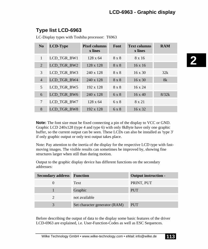
LCD-6963 - Graphic display
Wilke Technology GmbH • www.wilke-technology.com • eMail: [email protected]
2
113
Type list LCD-6963LC-Display types with Toshiba processor: T6963
No LCD-Type Pixel columnsx lines
Font Text columnsx lines
RAM
1 LCD_TGR_BW1 128 x 64 8 x 8 8 x 16
2 LCD_TGR_BW2 128 x 128 8 x 8 16 x 16
3 LCD_TGR_BW3 240 x 128 8 x 8 16 x 30 32k
4 LCD_TGR_BW4 240 x 128 8 x 8 16 x 30 8k
5 LCD_TGR_BW5 192 x 128 8 x 8 16 x 24
6 LCD_TGR_BW6 240 x 128 6 x 8 16 x 40 8/32k
7 LCD_TGR_BW7 128 x 64 6 x 8 8 x 21
8 LCD_TGR_BW8 192 x 128 6 x 8 16 x 32
Note: The font size must be fixed connecting a pin of the display to VCC or GND.Graphic LCD 240x128 (type 4 and type 6) with only 8kByte have only one graphicbuffer, so the current output can be seen. These LCDs can also be installed as 'type 3'if only graphic output or only text output takes place.
Note: Pay attention to the inertia of the display for the respective LCD type with fast-moving images. The visible results can sometimes be improved by, showing finestructures larger when still than during motion.
Output to the graphic display device has different functions on the secondaryaddresses:
Secondary address Function Output instruction -
0 Text PRINT, PUT
1 Graphic PUT
2 not available
3 Set character generator (RAM) PUT
Before describing the output of data to the display some basic features of the driverLCD-6963 are explained, i.e. User-Function-Codes as well as ESC Sequences.

Device driver
Wilke Technology GmbH • www.wilke-technology.com • eMail: [email protected]
2
114
Concerning output of data please see under 'Output on the graphic screen' page 132.Gaphic on LC-display is largely supported, though by functions (see chapter'Graphics' in the programming manual).
Connecting the graphic LC-displayA graphic LC-display requires the data bus and four further I/O lines from theBASIC-Tiger® module. The following table shows the standard pin assignment:
LCD-Pin-Function Pin name Pin-No.
BASIC-Tiger®
Pin-No.
Tiny-Tiger®
D0...D7 L60...L67 2...9 1...8
-WR L80 14 13
-RD L81 15 14
-CE L82 16 15
C/D L83 17 16
We recommend that you provide the 4 CTRL lines of the LCD with a Pull-UP resistorsince the Tiger-Pins have a high resistance during the Power-On Phase and the LCDcould enter an undefined status. <-CE> at least should be switched in this way. Except‘-CE’ the control lines can be shared with other devices, e.g. the analog extensionmodules EP11 to EP14 in connection with the device driver ANALOG3.TDD.
Moreover, the graphic LC-display also has a reset input alongside the power supplyand contrast adjustment. The display must have a RESET (see LCD documents)during a Power-ON and is thus normally connected to the System-RESET.(Remember: the reset pin of the BASIC-Tiger® or Tiny-Tiger® is not an output.)
Since LC-displays have their own controller they can crash or otherwise becomeunstable independent of the controlling environment. This can occur due to staticdischarges in the vicinity of the LC-display or crosstalk in the data cable, particularlywhen this is very long. Experience has shown the ground connection to be verycritical in long data cables. One remedy in such situations is to reset the LC-displayfrom the controlling module. A free port pin could be connected to the RESET-inputof the LCD so that the LCD can be reset under the control of the BASIC program.
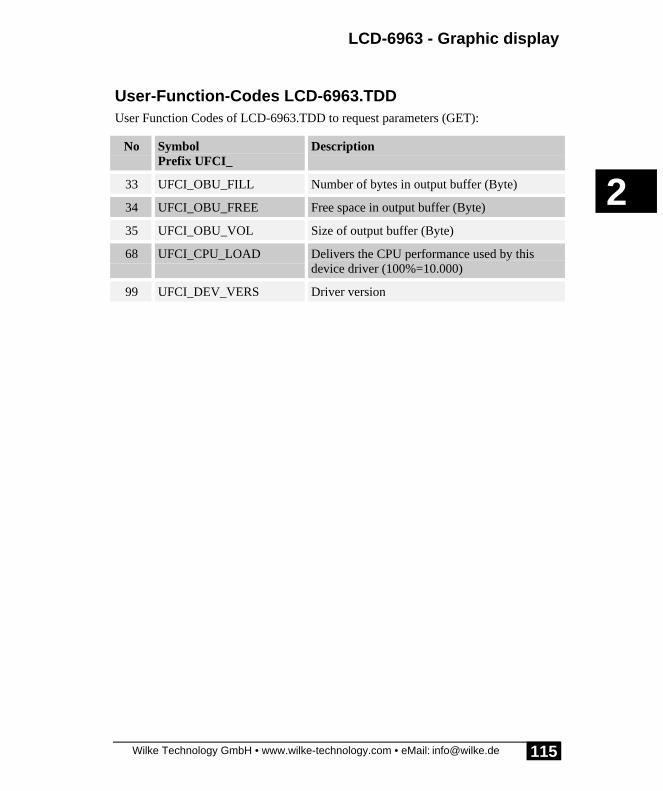
LCD-6963 - Graphic display
Wilke Technology GmbH • www.wilke-technology.com • eMail: [email protected]
2
115
User-Function-Codes LCD-6963.TDDUser Function Codes of LCD-6963.TDD to request parameters (GET):
No SymbolPrefix UFCI_
Description
33 UFCI_OBU_FILL Number of bytes in output buffer (Byte)
34 UFCI_OBU_FREE Free space in output buffer (Byte)
35 UFCI_OBU_VOL Size of output buffer (Byte)
68 UFCI_CPU_LOAD Delivers the CPU performance used by thisdevice driver (100%=10.000)
99 UFCI_DEV_VERS Driver version

Device driver
Wilke Technology GmbH • www.wilke-technology.com • eMail: [email protected]
2
116
User Function Codes of LCD-6963.TDD to set parameters (PUT):
No SymbolPrefix: UFCO_
Description
1 UFCO_IBU_ERASE Delete input buffer
33 UFCO_OBU_ERASE Delete output buffer
144 UFCO_LCD_TYPE Set new LCD type. UFCO_LCD_RESET mustfollow.
159 UFCO_CPU_LOAD Set relative CPU performance usable by thisdevice driver (4...88%)
156 UFCO_LCD_TXTSIZ Sets number of lines and number of charactersper line:1. parameter byte: number of lines2. parameter byte: number of characters per lineThe reset command must be given afterwards.
157 UFCO_LCD_LINE 2 parameter determines what happensa) at end of line:
0: continues on next line1: continues on the same line2: stops
b) at end of screen:
0: continues at home position1: continues on the beginning of the last line ofthe screen2: stops
158 UFCO_LCD_PARAM Sets all LCD parameters as set in INSTALL-line
159 UFCO_LCD_PWR sets CPU load to 4...128
176 UFCO_LCD_RESET resets LCD (by software only, newinitialization)
The device driver can be very demanding of the CPU, sometimes greatly restrictingaccess to CPU resources for other tasks. By using the User Function Code,UFCO_CPU_LOAD, the user can limit the percentage of CPU resources the drivercan use. This limit can be set to a value between 4% and 88% of total CPU resources.

LCD-6963 - Graphic display
Wilke Technology GmbH • www.wilke-technology.com • eMail: [email protected]
2
117
Control characters of the graphic LC-displayControl characters are written directly to the LCD-device with no ESC and EOS.
HOME <02> Sets the cursor in the top left corner
FS <05> Cursor 1 position to the right
BS <08> Cursor 1 position to the left
LF, DO <0Ah> Cursor 1 position down
UP <0Bh> Cursor 1 position up
CR <0Dh> Carriage return
PRINT #LCD, “<1>“;
moves the cursor to the ‘home’ position (X=0, Y=0). This can be directly followed byfurther text:
PRINT #LCD, “<2>Hello World“

Device driver
Wilke Technology GmbH • www.wilke-technology.com • eMail: [email protected]
2
118
ESC commands LCD-6963 (Text)Commands to the LCD1-6963 device driver can also be sent with the normal dataflow in PRINT or PUT instructions in the form of ESC sequences. The commandsequence then starts with <ESC> code, followed by a command character and avarying number of parameters depending on the command. The sequence ends withan EOS character.
ESC: <1Bh>
EOS: <F0h>
Command character: this is case-sensitive!
<27> X p1, p2, p3, ...pn <F0h>
EOS character
Parameter n
Parameter 1
Command X
ESC character
The arguments of the following ESC-commands (x, y, n) are always BYTES unlessotherwise specified. The commands are case-sensitive. �

LCD-6963 - Graphic display
Wilke Technology GmbH • www.wilke-technology.com • eMail: [email protected]
2
119
Summary :
ESC-SEQUENCE Description
ESC, A, x, y, EOS Absolute cursor address
ESC, c, n, EOS Define cursorn=0: Cursor = 1 Linen=1: Cursor = 2 Lines
n=7: Cursor = 8 Lines
Bit 3: 0=blink off, 1=blink on (n+10h)Bit 4: 0=with cursor, 1=without cursor (n+20h)
ESC, m, n, EOS Mode:Bits 4+3: Text and graphic operation00 = Mode OR01 = Mode XOR10 = Mode XOR11 = Mode ANDBit-0: 0 = Internal character set, 1 = Special char. set.
ESC, G, n, EOS Graphicn=0: offn=1: on
ESC, T, n, EOS Textn=0: offn=1: on
ESC sequences must always be output in a PRINT or PUT instruction. A number ofESC sequences can be output in an instruction if the line length allows.

Device driver
Wilke Technology GmbH • www.wilke-technology.com • eMail: [email protected]
2
120
LCD-6963 Position cursor: ESC APRINT #D, “<1Bh>A“; CHR$(x); CHR$(y); “<F0h>“;
Absolute positioning of the cursor on the display.
D is a constant, variable or expression of the data type BYTE,WORD, LONG in the range from 0...63 and stands for thedevice number of the driver.
x x-co-ordinate (column) at which the cursor is to be positioned.
y y-co-ordinate (line), at which the cursor is to be positioned.
Lines and columns are counted from 0. The possible value range depends on the LC-display used. Values for x and y which are too large will be set to the maximumvalue.
Program example:
'--------------------------------------------------------------------'Name: T69ESC_A.TIG'--------------------------------------------------------------------user_var_strict 'variables must be declared#include DEFINE_A.INC 'general defines#include LCD_4.INC 'definitions for LCD Typ 4#include GR_TK1.INC 'definitions for Graphic Toolkit
TASK MAIN 'begin task MAIN CALL Init_LCDpins 'init LCD pins 'LCD-4=240x128, 150 KB/s INSTALL_DEVICE #1,"LCD-6963.TDD",0,0,0EEH,LCD_TYPE,150,11H 'show various positions PRINT #1, "<1Bh>A<0><0><0F0h>X<3Ch>--0,0" PRINT #1, "0...29 column" PRINT #1, "0...15 line" PRINT #1, "<1Bh>A<1><5><0F0h>X<3Ch>--1,5" PRINT #1, "<1Bh>A<8><7><0F0h>15,7--<3Eh>X"END 'end task MAIN
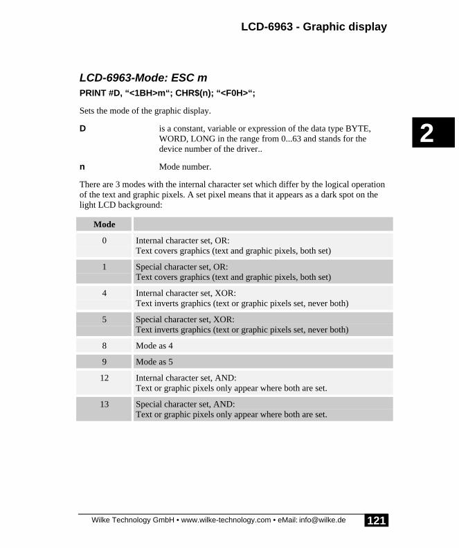
LCD-6963 - Graphic display
Wilke Technology GmbH • www.wilke-technology.com • eMail: [email protected]
2
121
LCD-6963-Mode: ESC mPRINT #D, “<1BH>m“; CHR$(n); “<F0H>“;
Sets the mode of the graphic display.
D is a constant, variable or expression of the data type BYTE,WORD, LONG in the range from 0...63 and stands for thedevice number of the driver..
n Mode number.
There are 3 modes with the internal character set which differ by the logical operationof the text and graphic pixels. A set pixel means that it appears as a dark spot on thelight LCD background:
Mode
0 Internal character set, OR:Text covers graphics (text and graphic pixels, both set)
1 Special character set, OR:Text covers graphics (text and graphic pixels, both set)
4 Internal character set, XOR:Text inverts graphics (text or graphic pixels set, never both)
5 Special character set, XOR:Text inverts graphics (text or graphic pixels set, never both)
8 Mode as 4
9 Mode as 5
12 Internal character set, AND:Text or graphic pixels only appear where both are set.
13 Special character set, AND:Text or graphic pixels only appear where both are set.

Device driver
Wilke Technology GmbH • www.wilke-technology.com • eMail: [email protected]
2
122
Program example:
'--------------------------------------------------------------------'Name: T69ESC_M.TIG'--------------------------------------------------------------------user_var_strict 'variables must be declared#include DEFINE_A.INC 'general defines#include LCD_4.INC 'definitions for LCD Typ 4#include GR_TK1.INC 'definitions for Graphic Toolkit
DATALABEL T69MGR_M
TASK MAIN 'begin task MAINT69MGR_M::DATA FILTER "T69MGR_M.BMP", "GRAPHFLT", 0 'load graphic BYTE I STRING GCLR$(130) 'string clears display
CALL Init_LCDpins 'init LCD pins 'LCD-4=240x128, 150 KB/s INSTALL_DEVICE #1,"LCD-6963.TDD",0,0,0EEH,LCD_TYPE,150,11H
GCLR$ = "<2>" 'create GCLR string LOOP 16 GCLR$ = GCLR$ + " " ENDLOOP GCLR$ = GCLR$ + "<2>"
PRINT #1, "<1Bh>T<1><0F0h>" 'set text on PRINT #1, "<1Bh>G<1><0F0h>" 'set graphic on PUT #1, #1, T69MGR_M, 0, 0, GR_SIZE'output graphic WAIT_DURATION 1000 'wait 1 sec PRINT #1, "<1Bh>m<0><0F0h>"; 'mode OR FOR I = 0 TO 7 PRINT #1, "mode OR mode OR "; NEXT WAIT_DURATION 3000 'wait 3 sec
PRINT #1, GCLR$; PRINT #1, "<1Bh>m<1><0F0h>"; 'mode XOR FOR I = 0 TO 7 PRINT #1, "mode XORmode XOR"; NEXT WAIT_DURATION 3000 'wait 3 sec
PRINT #1, GCLR$; PRINT #1, "<1Bh>m<3><0F0h>"; 'mode AND FOR I = 0 TO 7 PRINT #1, "mode ANDmode AND"; NEXTEND 'end task MAIN

LCD-6963 - Graphic display
Wilke Technology GmbH • www.wilke-technology.com • eMail: [email protected]
2
123
Graphic display on / off: ESC GPRINT #D, “<1BH>G“; CHR$(n); “<F0H>“;
Switches the display's graphics on or off.
D is a constant, variable or expression of the data type BYTE,WORD, LONG in the range from 0...63 and stands for thedevice number of the driver..
n 0 = off, 1 = on.
This ESC sequences switches the graphics on the display on or off. The text content isnot affected.

Device driver
Wilke Technology GmbH • www.wilke-technology.com • eMail: [email protected]
2
124
Program example:
'--------------------------------------------------------------------' Name: T69ESC_G.TIG'--------------------------------------------------------------------user_var_strict 'variables must be declared#include DEFINE_A.INC 'general defines#include LCD_4.INC 'definitions for LCD Typ 4#include GR_TK1.INC 'definitions for Graphic Toolkit
DATALABEL T69MGR
TASK MAIN 'begin task MAINT69MGR::DATA FILTER "T69MGR.BMP", "GRAPHFLT", 0 'load graphic
CALL Init_LCDpins 'init LCD pins 'LCD-4=240x128, 150 KB/s INSTALL_DEVICE #1,"LCD-6963.TDD",0,0,0EEH,LCD_TYPE,150,11H
PRINT #1, "<1Bh>T<1><0F0h><1Bh>A<4><0><0F0h>Text ON" PRINT #1, "<1Bh>m<1><0F0h>"; 'mode XOR PUT #1, #1, T69MGR, 0, 0, GR_SIZE'output graphic PRINT #1, "<1Bh>G<1><0F0h><1Bh>A<3><3><0F0h>Graphic ON " WAIT_DURATION 3000 'wait 3 sec PRINT #1, "<1Bh>G<0><0F0h><1Bh>A<3><3><0F0h>Graphic OFF" WAIT_DURATION 3000 'wait 3 sec PRINT #1, "<1Bh>G<1><0F0h><1Bh>A<3><3><0F0h>Graphic ON "END 'end task MAIN
More information on the special characters of the LC-display can be found on pages63f.
See also: Esc command S (activate character set) and Esc command R (reset characterset).

LCD-6963 - Graphic display
Wilke Technology GmbH • www.wilke-technology.com • eMail: [email protected]
2
125
Text display on / off: ESC TPRINT #D, “<1BH>T“; CHR$(n); “<F0H>“;
Switches the display's text on or off.
D is a constant, variable or expression of the data type BYTE,WORD, LONG in the range from 0...63 and stands for thedevice number of the driver.
n 0 = off, 1 = on.
This ESC sequences switches the text on the display on or off. The graphic content isnot affected.
Program example:
'--------------------------------------------------------------------'Name: T69ESC_T.TIG'--------------------------------------------------------------------user_var_strict 'variables must be declared#include DEFINE_A.INC 'general defines#include LCD_4.INC 'definitions for LCD Typ 4#include GR_TK1.INC 'definitions for Graphic Toolkit
DATALABEL T69MGR
TASK MAIN 'begin task MAINT69MGR::DATA FILTER "T69MGR.BMP", "GRAPHFLT", 0 'load graphic
CALL Init_LCDpins 'init LCD pins 'LCD-4=240x128, 150 KB/s INSTALL_DEVICE #1,"LCD-6963.TDD",0,0,0EEH,LCD_TYPE,150,11H
PRINT #1, "<1Bh>G<1><0F0h>Graphic ON" PRINT #1, "<1Bh>m<1><0F0h>"; 'mode XOR PUT #1, #1, T69MGR, 0, 0, GR_SIZE'output graphic PRINT #1, "<1Bh>T<1><0F0h><1Bh>A<3><3><0F0h>Text ON " WAIT_DURATION 3000 'wait 3 sec PRINT #1, "<1Bh>T<0><0F0h>" WAIT_DURATION 3000 'wait 3 sec PRINT #1, "<1Bh>T<1><0F0h><1Bh>A<3><3><0F0h>&For 3sec<1Bh>A<2><4><0F0h>Text was OFF"END 'end task MAIN

Device driver
Wilke Technology GmbH • www.wilke-technology.com • eMail: [email protected]
2
126
LCD-6963 Define cursor: ESC cPRINT #D, “<1Bh>c“; CHR$(n); “<F0h>“;
Defines the appearance of the cursor on the display.
D is a constant, variable or expression of the data type BYTE,WORD, LONG in the range from 0...63 and stands for thedevice number of the driver.
n Determines the form of the cursorn=0: cursor is a linen=1: cursor is two lines...n=7: cursor is eight linesBit-3: Cursor (0...7) + 8 or -> cursor blinkingBit-4: Cursor (0...7) + 16 or +10h -> cursor off

LCD-6963 - Graphic display
Wilke Technology GmbH • www.wilke-technology.com • eMail: [email protected]
2
127
Program example:
'--------------------------------------------------------------------'Name: T69ESC_C.TIG'--------------------------------------------------------------------user_var_strict 'variables must be declared#include DEFINE_A.INC 'general defines#include LCD_4.INC 'definitions for LCD Typ 4#include GR_TK1.INC 'definitions for Graphic Toolkit
TASK MAIN 'begin task MAIN BYTE N
CALL Init_LCDpins 'init LCD pins 'LCD-4=240x128, 150 KB/s INSTALL_DEVICE #1,"LCD-6963.TDD",0,0,0EEH,LCD_TYPE,150,11H
PRINT #1,"<1>Cursor modes:" PRINT #1,"0...7: constant" PRINT #1,"8...15: blinking" FOR N=0 TO 15 'various shapes for cursor PRINT #1,"<1BH>c";CHR$(N);"<0F0H>"; PRINT #1,"<1BH>A<0><4><0F0H>n = ";N;" A";CHR$(8); WAIT_DURATION 1000 'wait 1 sec NEXT PRINT #1,"<1BH>c";CHR$(16);"<0F0H>"; '---> without cursor ! PRINT #1,"<1BH>A<0><4><0F0H>n = 16 "; PRINT #1,"<1BH>A<0><6><0F0H>no Cursor: A<8>";END 'end task MAIN
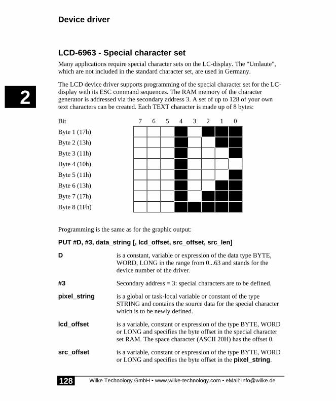
Device driver
Wilke Technology GmbH • www.wilke-technology.com • eMail: [email protected]
2
128
LCD-6963 - Special character setMany applications require special character sets on the LC-display. The "Umlaute",which are not included in the standard character set, are used in Germany.
The LCD device driver supports programming of the special character set for the LC-display with its ESC command sequences. The RAM memory of the charactergenerator is addressed via the secondary address 3. A set of up to 128 of your owntext characters can be created. Each TEXT character is made up of 8 bytes:
Bit 7 6 5 4 3 2 1 0
Byte 1 (17h)
Byte 2 (13h)
Byte 3 (11h)
Byte 4 (10h)
Byte 5 (11h)
Byte 6 (13h)
Byte 7 (17h)
Byte 8 (1Fh)
Programming is the same as for the graphic output:
PUT #D, #3, data_string [, lcd_offset, src_offset, src_len]
D is a constant, variable or expression of the data type BYTE,WORD, LONG in the range from 0...63 and stands for thedevice number of the driver.
#3 Secondary address = 3: special characters are to be defined.
pixel_string is a global or task-local variable or constant of the typeSTRING and contains the source data for the special characterwhich is to be newly defined.
lcd_offset is a variable, constant or expression of the type BYTE, WORDor LONG and specifies the byte offset in the special characterset RAM. The space character (ASCII 20H) has the offset 0.
src_offset is a variable, constant or expression of the type BYTE, WORDor LONG and specifies the byte offset in the pixel_string.

LCD-6963 - Graphic display
Wilke Technology GmbH • www.wilke-technology.com • eMail: [email protected]
2
129
This means that only part of the special character can be newlydefined.
scr_len is a variable, constant or expression of the type BYTE, WORDor LONG and specifies the number of bytes to be output aftersrc_offset.
If ‘lcd_offset’ = 0 the data record for space (ASCII-Code = 20H) begins, and after8 bytes this is followed by the data record for ‘!’ (ASCII 21H), etc. The completeRAM character generator comprises 128 text characters of 8 bytes each, whoselowest-order 5 bits are used for the display. This means that a total of 1024 bytesdescribe the special character set. It is practical to always set the entire charactergenerator so that all text characters in the code range from 20H...9FH lead to definedresults. If individual text characters or character groups are to altered later on in theprogram run, all that needs be done is to reset these bytes.
You can switch between an internal and external character generator with the ESCsequence "ESC-m". At the same time this command determines the mode for text andgraphic pixel operations.

Device driver
Wilke Technology GmbH • www.wilke-technology.com • eMail: [email protected]
2
130
Program example:
'--------------------------------------------------------------------'Name: T69SPEC1.TIG'--------------------------------------------------------------------user_var_strict 'variables must be declared#include DEFINE_A.INC 'general defines#include LCD_4.INC 'definitions for LCD Typ 4#include GR_TK1.INC 'definitions for Graphic Toolkit
STRING M$(8), S$(8) 'strings for special chars
TASK MAIN 'begin task MAIN CALL Init_LCDpins 'init LCD pins 'LCD-4=240x128, 150 KB/s INSTALL_DEVICE #1,"LCD-6963.TDD",0,0,0EEH,LCD_TYPE,150,11H
PRINT #1, "<1Bh>m<0><0F0h>" 'internal char set PRINT #1, " 1 1 1 1 1" 'output which changes WAIT_DURATION 1000 'after 1 sec
S$ = "&. . . . . . . . & 'Space. . . . . . . . &. . . . . . . . &. . . . . . . . &. . . . . . . . &. . . . . . . . &. . . . . . . . &. . . . . . . . "B
M$ = "&. . . . . * . . & 'man. . . . * * * . &. . . . . * . . &. . . * * * * * &. . . . . * . . &. . . . * . * . &. . . * . . . * &. . . . . . . . "B
PUT #1, #3, S$ 'set special char for ' ' PUT #1, #3, M$, (31h-20h)*8 'set special char for '1'
PRINT #1, "<1Bh>m<8><0F0h>" 'external char setEND 'end task MAIN
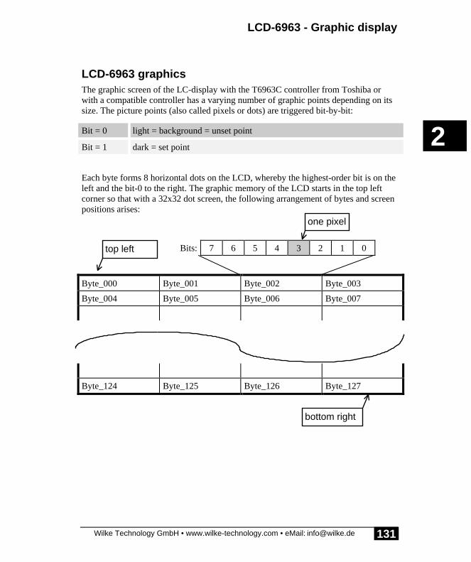
LCD-6963 - Graphic display
Wilke Technology GmbH • www.wilke-technology.com • eMail: [email protected]
2
131
LCD-6963 graphicsThe graphic screen of the LC-display with the T6963C controller from Toshiba orwith a compatible controller has a varying number of graphic points depending on itssize. The picture points (also called pixels or dots) are triggered bit-by-bit:
Bit = 0 light = background = unset point
Bit = 1 dark = set point
Each byte forms 8 horizontal dots on the LCD, whereby the highest-order bit is on theleft and the bit-0 to the right. The graphic memory of the LCD starts in the top leftcorner so that with a 32x32 dot screen, the following arrangement of bytes and screenpositions arises:
Bits: 7 6 5 4 3 2 1 0
Byte_000 Byte_001 Byte_002 Byte_003
Byte_004 Byte_005 Byte_006 Byte_007
Byte_124 Byte_125 Byte_126 Byte_127
top left
bottom right
one pixel

Device driver
Wilke Technology GmbH • www.wilke-technology.com • eMail: [email protected]
2
132
Output on the graphic screenPUT #D, #1, pixel_string [, lcd_offset, src_offset, src_len]
D is a constant, variable or expression of the data type BYTE,WORD, LONG in the range from 0...63 and stands for thedevice number of the driver.
#1 Secondary address = 1: graphics are output
pixel_string is a global or task-local variable or constant of the typeSTRING and contains the source data for the graphic to beshown on the LCD.
lcd_offset is a variable, constant or expression of the type BYTE, WORDor LONG and specifies the byte offset in the LCD graphicRAM. The top left corner of the screen has the offset 0.
src_offset is a variable, constant or expression of the type BYTE, WORDor LONG and specifies the byte offset in the pixel_string.This means that only part of the graphic data can be output.
scr_len is a variable, constant or expression of the type BYTE, WORDor LONG and specifies the number of bytes to be output aftersrc_offset..
Some examples of graphic output instructions:
PUT #7, #1, A$ ' Output dots starting in top left cornerPUT #7, #1, B$,64 ' Skip 64 x 8 dots in the LCDPUT #7, #1, C$,0,0,128 ' Show 128 x 8 dots in top of LCD
The graphic is only output with the instruction PUT, never with PRINT. The pixelstring must always exist! This means that variables with a limited life, e.g. localstrings (in subroutines) or temporary strings (expressions) are not allowed. Correct:global or task-local strings.
The driver writes graphic data alternately in one of two internal graphic buffers. Theadvantage of this is that all pixels are visible simultaneously, even with a fast picturerefresh rate. This strategy means that there are always 2 internal display storages:
�

LCD-6963 - Graphic display
Wilke Technology GmbH • www.wilke-technology.com • eMail: [email protected]
2
133
• the visible graphic storage last described with PUT,• the last but one graphic storage, which will also be the one to be shown next
If the whole screen is not written, each pixel which is not re-written receives thevalues of the LAST but one graphic output and not the dots of the graphic outputbeing shown. The following diagram thus shows that after writing part of the outputin step 3, the previously visible ‘44444’ does not appear as ‘55444’ but ‘55333’:
Step before writinginvisible
after writingvisible
Buffer a: 22222
Buffer b: 11111
1. write: 33333 Buffer b: 33333
Buffer a: 22222
2. write: 44444 Buffer a: 44444
Buffer b: 33333
3. write: 55 Buffer b: 55333
Buffer a: 44444
If pixel_string=““ (empty), only the internal buffer is switched over.
Graphic outputs normally contain considerably more data than text outputs. This iswhy this device driver works with a different access method than, e.g., the driver‘LCD1.TDD’.
Instead of transporting data bytes from a source buffer (in the BASIC program) to atarget buffer (in the device driver), a ‘direct access’ is carried out. With this methodthe PUT instruction does not transfer any data bytes, rather, the device driver receivesa Pointer to the place (data string ) where the source data is to be found.
This method has a number of advantages, in particular, storage space is spared and theprogram execution is much faster. Although the pointer is transferred immediatelyafter execution of the PUT instruction, no data has been sent. Nevertheless, the nextBASIC instruction is carried out whilst the device driver transfers the data to thegraphic LCD. You should thus pay attention to the following when using this driver:
The source buffer (string) must always exist, i.e. it must be global or task-local. Thismeans that variables with a limited life, e.g. local strings (in subroutines) or temporarystrings (expressions) are not allowed.
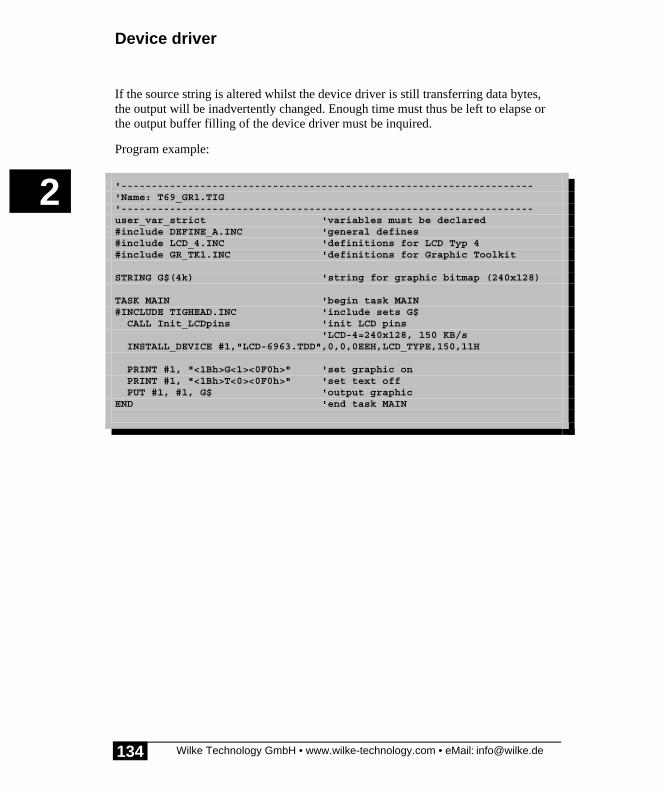
Device driver
Wilke Technology GmbH • www.wilke-technology.com • eMail: [email protected]
2
134
If the source string is altered whilst the device driver is still transferring data bytes,the output will be inadvertently changed. Enough time must thus be left to elapse orthe output buffer filling of the device driver must be inquired.
Program example:
'--------------------------------------------------------------------'Name: T69_GR1.TIG'--------------------------------------------------------------------user_var_strict 'variables must be declared#include DEFINE_A.INC 'general defines#include LCD_4.INC 'definitions for LCD Typ 4#include GR_TK1.INC 'definitions for Graphic Toolkit
STRING G$(4k) 'string for graphic bitmap (240x128)
TASK MAIN 'begin task MAIN#INCLUDE TIGHEAD.INC 'include sets G$ CALL Init_LCDpins 'init LCD pins 'LCD-4=240x128, 150 KB/s INSTALL_DEVICE #1,"LCD-6963.TDD",0,0,0EEH,LCD_TYPE,150,11H
PRINT #1, "<1Bh>G<1><0F0h>" 'set graphic on PRINT #1, "<1Bh>T<0><0F0h>" 'set text off PUT #1, #1, G$ 'output graphicEND 'end task MAIN

LCD-6963 - Graphic display
Wilke Technology GmbH • www.wilke-technology.com • eMail: [email protected]
2
135
Graphic LCD functions (overview)The folllowing table shows the numerous functions developed especially for graphicson LCDs. The Programmig Manual contains a chapter for the graphic functions.
Function name Pixel-graphi
c
Vectorgraphi
c
OR2 � 2 graphics are overlayed withunconditioned OR
OR3 � 3 graphics are overlayed withunconditioned OR
OR4 � 4 graphics are overlayed withunconditioned OR
AND2 � 2 graphics are overlayed withunconditioned AND
AND3 � 3 graphics are overlayed withunconditioned AND
AND4 � 4 graphics are overlayed withunconditioned AND
XOR1 � 2 graphics are overlayed withunconditioned XOR
GRAPHIC_MASK_COPY � 2 graphics are combined using amask
GRAPHIC_MIRROR � mirrors agraphic: X-, Y- or X+Y axis
GRAPHIC_EXP_STRI � expands graphic bytes
GRAPHIC_COPY � copies graphic window
GRAPHIC_FILL_MASK � fills a square mask into a graphic
INVERT � inverts pixel values
DRAW_LINE � begins a line inside graphic area
DRAW_NEXT_LINE � continues a line inside graphic area
CLOSE_LINE � closes a line

Device driver
Wilke Technology GmbH • www.wilke-technology.com • eMail: [email protected]
2
136
Function name Pixel-graphi
c
Vectorgraphi
c
END_LINE � ends a line
SET_ROTATION � sets rotation angle 0,01-Grad
SET_SCALE � sets scale (100% = 1000)
SET_BASE � sets Basis point X/Y
SET_GRAREA � sets graphic area: destin + B x H
SET_DOT � sets DOT to 0 or 1
FILL_AREA � fills graphic area
Supporting functions:
DISTANCE calculates distance between 2 co-ordinates
QUICK_WORD_SIN calculates fast sine in WORD
QUICK_WORD_COS calculates fast cosine in WORD

MF-II-PC Keyboard
Wilke Technology GmbH • www.wilke-technology.com • eMail: [email protected]
2
137
MF-II-PC KeyboardThe device driver ‘MF2_xxxx’ enables the connection of a PC keyboard of the typeMF-II. Only 2 resistors are needed as an external component for this purpose alongwith the keyboard socket.
File name:: MF2_8xpp.TDD
INSTALL DEVICE #D, "MF2_8xPp.TDD"
D is a constant, variable or expression of the data type BYTE,WORD, LONG in the range 0...63 and stands for the devicenumber of the driver.
x in the file name specifies the pin to connect the keyboard'sclock line.
Pp in the file name stands for:P: internal portp: pin for keyboard's data line.
The clock and the data line have a pull-up resistor against VCC. The power supply forthe keyboard is provided at the socket. The current consumption can be found in thedata sheet for the keyboard.
Size and level of the input buffer as well as the driver version can be inquired with theUser-Function codes.

Device driver
Wilke Technology GmbH • www.wilke-technology.com • eMail: [email protected]
2
138
Example of a connection for an MF-II keyboard:

MF-II-PC Keyboard
Wilke Technology GmbH • www.wilke-technology.com • eMail: [email protected]
2
139
Since an MF-II keyboard sends no ASCII codes but requires further code conversionsteps, rather complicated measures are required to obtain the desired key function. Asa basis, certain Include files are provided along with the example program which canbe adjusted to your needs. MF2_TR.INC is the only Include file to be integrated in theapplication. MF2_TR.INC itself integrates all further Include files.
The application calls subroutines which are found in the files MF2_TR.INC,MF2_TR_D.INC. This is where conversion to ASCII takes place. In the next layerMF2_PH.INC, MF2_PH_D.INC, the (physical) connection to the driver and thus thekeyboard is carried out.
The initialization 'InitKeybTables' is called once before using the keyboard. Thenumber of the language (1=English, 2=German, 3=English and German) is transferredas the argument.
The subroutine 'InitKeybDev' with the device number as argument (WORD) is alsocalled once. If the driver is integrated a number of times, 'InitKeybDev' will also becalled a number of times with the device number.
The subroutine 'GetAsciiKey’ delivers in a WORD:
• with no signal 0000h• the character if the ASCII-character is in the low-byte, the scan code if in the
high-byte• 0 if the key with the extended code is in the low-byte, the scan code if in the
high-byte

Device driver
Wilke Technology GmbH • www.wilke-technology.com • eMail: [email protected]
2
140
The subroutine 'CheckKeybFlags' provides information on the momentary status ofspecial keys such as Ctrl, Alt, Shift, etc.
Byte 0
Bit 0: right Shift key pressedBit 1: left Shift key pressedBit 2: Ctrl key pressedBit 3: ALT key pressedBit 4: Scroll-Lock is activeBit 5: Num-Lock is activeBit 6: Caps-Lock is activeBit 7: Insert is active
Byte 1
Bit 0: left Ctrl key pressedBit 1: left ALT key pressedBit 2: System-Request is pressedBit 3: Pause key is toggledBit 4: Scroll-Lock key pressedBit 5: Num-Lock key pressedBit 6: Caps-Lock key pressedBit 7: Insert key pressed
Byte 2 (LED)
Bit 0: Scroll-Lock LEDBit 1: Num-Lock LEDBit 2: Caps-Lock LEDfurther bits not used.
Byte 3
Bit 0: last code was the 'E1 hidden code'Bit 1: last code was the 'E0 hidden code'Bit 2: right Ctrl key pressedBit 3: right ALT key pressedfurther bits not used.

MF-II-PC Keyboard
Wilke Technology GmbH • www.wilke-technology.com • eMail: [email protected]
2
141
'MF2_PH.INC' contains some useful subroutines:
Subroutine (arguments) Function
ResetKbd ( WORD wDevId ) RESET keyboard
SetKbdTypematicRate ( WORD wDevId; BYTE bTpRate )
sets Typematic rate of the MF-IIkeyboard
SetKbdIndicators ( WORD wDevId; BYTE bLEDsMask )
set the LED# of the MF-II keyboard(bLEDsMask, 0=off, 1=on):Bit 0: Scroll-LockBit 1: Num-LockBit 2 Caps-Lock
ClearKbdBuffer ( WORD wDevId ) deletes the MF-II keyboard buffer
GetKbdScanCode ( WORD wDevId; VAR BYTE bCode )
gets a character from the keyboard buffer.If the buffer is empty, 'bCode' remainsunchanged.
SetKbdScanCodeTable ( WORD wDevId; BYTE bTableId )
sets the Scan-Code table for the keyboardin 'bTableId'
GetKbdBufferFillSize(WORD wDevId;VAR LONG lBufSize )
reads the level of the keyboard buffer
All subroutines for the MF-II keyboard are re-entrant, i.e. several tasks can be usedsimultaneously.
Note: Scan-Code-Sets: the MF-II subroutines are written for the Scan-Code-Set 1.
The following example program shows that using the keyboard has become easierfrom a user's point of view with the enclosed Include files.

Device driver
Wilke Technology GmbH • www.wilke-technology.com • eMail: [email protected]
2
142
Program example:
'--------------------------------------------------------------------'Name: MF2_1.TIG'shows how to use MF-II keyboard with BASIC Tiger'--------------------------------------------------------------------'connect the 4 relevant Pins of an MF-II keyboard:
'--------------------------------------------------------------------user var strict 'check var declarations#include UFUNC3.INC 'User Function Codes#include DEFINE_A.INC 'general symbol definitions#include MF2_TR.INC
WORD wKeybDevId1 'Keyboard Device NumberLONG lKeybExtFlags1 'Keyboard FlagsBYTE bKeybActLang1 'Keyboard Layout(Language)
'--------------------------------------------------------------------TASK Main WORD wKey 'key (WORD) BYTE bIsActive LONG lComplexMask
'install LCD-driver (BASIC-Tiger) INSTALL DEVICE #LCD, "LCD1.TDD"'install LCD-driver (TINY-Tiger)'INSTALL DEVICE #1, "LCD1.TDD", 0, 0, 0, 0, 0, 0, 80h, 8
INSTALL DEVICE #KEYB1, "MF2_8081.TDD" 'L80=clock, L81=data
wKeybDevId1 = KEYB1 'initialize the keyboard variables lKeybExtFlags1 = 0 bKeybActLang1 = LANG_GERMAN
CALL InitKeybTables( bKeybActLang1 ) 'init step 1 CALL InitKeybDev( wKeybDevId1 ) 'init step 2
LOOP 9999999 'many loops 'read a key from keyboard buffer translated into ASCII CALL GetAsciiKey(wKeybDevId1, lKeybExtFlags1, bKeybActLang1, wKey) IF wKey <> 0 THEN 'if valid code PRINT #LCD, CHR$(wKey); 'show on LCD ENDIF ENDLOOPEND

Parallel printer
Wilke Technology GmbH • www.wilke-technology.com • eMail: [email protected]
2
143
Parallel printerThe device driver ‘PRN1’ allows you to connect a parallel Printer without additionalcircuitry.
File name: PRN1.TDD (PRN1_.TDD with smaller buffers)
INSTALL DEVICE #D, "PRN1.TDD" [, P1, ..., P7 ]
D is a constant, a variable or expression of the data type BYTE,WORD, LONG in the range from 0→63 and stands for thedevice number of the drivers.
Data bus L60→L67 (Pin-No. 2→9) is the data bus, which is also usedfor LCD, extended I/O-Pins and keyboard).
Busy Pin L70 (Pin-No. 10) is the input pin for the 'busy' signal.
Strobe Pin L71 (Pin-No. 11) is the output pin for strobe signal.
P1...P7 are further parameters which modify the standard pinconfiguration of the PRN1 drivers. The sequence of theparameter input must be retained. The values entered must alsobe correct. However, you do not have to specify all 7parameters.
Description of the parameter
P1 Reserved (set to 0)
P2 Number of burst characters
P3 Logic port address of the data bus (default=6)
P4 Logic port address for signal ‘busy’ (default=7)
P5 True-Bit mask for signal ‘busy’, specifies bit position (default=1)
P6 Logic port address for signal ‘strobe’ (default=7)
P7 True-Bit mask for signal ‘strobe’, specifies bit position. (default=2)
The number of burst characters can be set for very fast devices. Characters aretransferred very quickly in groups (burst).

Device driver
Wilke Technology GmbH • www.wilke-technology.com • eMail: [email protected]
2
144
The driver PRN1 driver and the LCD1 driver as well as the extended I/Os can beoperated simultaneously. Data which is output on these device drivers is initiallyinternally buffered (1-4 Kbyte). Output on the printer is by means of the instructionsPRINT, PRINT_USING or PUT.
In order to have more than one parallel output the device driver may be installedseveral times. The pins for ‘-strobe’ and ‘busy’ must then be installed to different I/Opins.
Size, filling level, and remaining space in the input buffer can be questioned withUser Function Codes (page 18 and following pages).
Example of a 36-pin Centronics connector:
Consult your printer manual to determine whether the printer requires certain signallevels on other lines. The driver serves the data bus, ‘strobe’ and pays attention to the‘busy’ signal.
���

Parallel printer
Wilke Technology GmbH • www.wilke-technology.com • eMail: [email protected]
2
145
Program example:
'--------------------------------------------------------------------'Name: PRN1.TIG'--------------------------------------------------------------------TASK MAIN 'begin task MAIN'install LCD-driver (BASIC-Tiger) INSTALL DEVICE #1, "LCD1.TDD"'install LCD-driver (TINY-Tiger)'INSTALL DEVICE #1, "LCD1.TDD", 0, 0, 0, 0, 0, 0, 80h, 8 INSTALL_DEVICE #5, "PRN1_K1.TDD" 'install printer-driver
PRINT #1, "Attention: printing" 'output to LCD PRINT #5, "Hello printer<12>" 'output to printer w. FFEND 'end task MAIN

Device driver
Wilke Technology GmbH • www.wilke-technology.com • eMail: [email protected]
2
146
Empty Page

Parallel input
Wilke Technology GmbH • www.wilke-technology.com • eMail: [email protected]
2
147
Parallel inputThe device driver ‘PIN1’ creates a parallel input using only a few electroniccomponents.
File name: PIN1.TDD (PIN1_.TDD with smaller buffers)
INSTALL DEVICE #D, "PIN1.TDD" [ P1, , P7 ]
D is a constant, a variable or expression of the data type BYTE,WORD, LONG in the range from 0→63 and stands for thedevice number of the drivers.
P1...P7 are further parameters setting the pin usage of PRN1.Parameters must be given in the order shown in the table below.It is not necessary to give all 7 parameters.
The external circuit of the parallel input latches the data byte with the strobe-signal.The strobe signal also sets a flip-flop indicating the Tiger-Module that a data byte isin the latch. The flip-flop delivers the busy signal for the external device.
The Tiger-Module reads the data byte setting the read line ‘low’. This resets the flip-flop. The busy line will still remain high for a while through the R-C-circuit.
Description
P1 No. of wait loops
P2 No. of burst characters
P3 Logical port address of data bus (standard L60...L67)
P4 Logical port address for data-valid (strobe latch, standard L80)
P5 True bit mask for data-valid, gives bit position (standard low).
P6 Logical port address for read signal
P7 True bit mask for read signal, gives bit position (standard low).
Parameter 1 determines how long the input routine will wait for further inputcharacters. Usually one character is read every 1msec. Parameter 2 determines howmany characters will be read in this burst mode.
The device drivers PIN1 (parallel-in), PRN1 (parallel-out), LCD1 as well as extendedI/O are supported at the same time. Data read on the parallel input are stored in the

Device driver
Wilke Technology GmbH • www.wilke-technology.com • eMail: [email protected]
2
148
device drivers input buffer. The instructions GET, INPUT, or INPUT_LINE are usedto read the buffer content.
In order to have more than one parallel input the device driver may be installedseveral times. The pins for ‘-strobe’ and ‘read’ must then be installed to different I/Opins.
Size, filling level, and remaining space in the input buffer can be questioned withUser Function Codes (page 18 and following pages).
Example of parallel input:
The timing for ‘busy’ is determined by the R-C-circuit and can be adapted ifnecessary.
���

Parallel input
Wilke Technology GmbH • www.wilke-technology.com • eMail: [email protected]
2
149
Consult the manual of the sending device to determine whether certain signal levelson other lines are required. The driver needs the data bus and ‘strobe’. The externalcircuit generates the ‘busy’ signal.
User-Function-Codes of PIN1.TDDUser-Function-Codes (UFC) for the input instruction GET:
No SymbolPrefix UFCI_
Description
1 UFCI_IBU_FILL No. of bytes in input buffer (Byte)
2 UFCI_IBU_FREE Free space in input buffer (Byte)
3 UFCI_IBU_VOL Size of input buffer (Byte)
65 UFCI_LAST_ERRC Last error code
99 UFCI_DEV_VERS Driver version
User-Function-Codes for output (instruction PUT):
No SymbolPrefix: UFCO_
Description
1 UFCO_IBU_ERASE Delete input buffer

Device driver
Wilke Technology GmbH • www.wilke-technology.com • eMail: [email protected]
2
150
Program example:
'--------------------------------------------------------------------'Name: PIN1.TIG'--------------------------------------------------------------------TASK Main 'begin task MAIN'install LCD-driver (BASIC-Tiger) INSTALL DEVICE #1, "LCD1.TDD"'install LCD-driver (TINY-Tiger)'INSTALL DEVICE #1, "LCD1.TDD", 0, 0, 0, 0, 0, 0, 80h, 8 INSTALL_DEVICE #2, "PIN1_K05.TDD" 'install parallel-in driver
PRINT #1, "<1>Parallel In" LOOP 999999999 'many loops GET #2, 1, A$ 'read from parallel port IF A$ <> "" THEN 'if data, PRINT #1, A$; 'output to LC-display ENDIF ENDLOOPEND 'end task MAIN
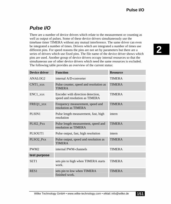
Pulse I/O
Wilke Technology GmbH • www.wilke-technology.com • eMail: [email protected]
2
151
Pulse I/OThere are a number of device drivers which relate to the measurement or counting aswell as output of pulses. Some of these device drivers simultaneously use thetimebase timer TIMERA without any mutual interference. The same driver can evenbe integrated a number of times. Drivers which are integrated a number of times usedifferent pins. For speed reasons the pins are not set by parameters but there are aseries of drivers which use fixed pins. The file name of the device driver shows whichpins are used. Another group of device drivers occupy internal resources so that thesimultaneous use of other device drivers which need the same resources is excluded.The following table provides an overview of the current status:
Device driver Function Resource
ANALOG2 internal A/D-converter TIMERA
CNT1_xxx Pulse counter, speed and resolution asTIMERA
TIMERA
ENC1_xxx Encoder with direction detection,speed and resolution as TIMERA
TIMERA
FREQ1_xxx Frequency measurement, speed andresolution as TIMERA
TIMERA
PLSIN1 Pulse length measurement, fast, highresolution
intern
PLSI2_Pxx Pulse length measurement, speed andresolution as TIMERA
TIMERA
PLSOUT1 Pulse output, fast, high resolution intern
PLSO2_Pxx Pulse output, speed and resolution asTIMERA
TIMERA
PWM2 internal PWM-channels TIMERA
test purpose
SET1 sets pin to high when TIMERA startswork.
TIMERA
RES1 sets pin to low when TIMERAfinished work.
TIMERA

Device driver
Wilke Technology GmbH • www.wilke-technology.com • eMail: [email protected]
2
152
The timebase driver TIMERA can be set to a maximum of 12.5kHz. This leads to atheoretical upper limit of 6.25 kHz for all pulse device drivers which use TIMERA.For drivers which measure pulse lengths of frequency it is not practical to adjust theTIMERA during measurement since otherwise values occur in the results bufferwhose unit is not known. More information on the TIMERA drive can be found frompage 365.

Count pulses
Wilke Technology GmbH • www.wilke-technology.com • eMail: [email protected]
2
153
Count pulsesThis device driver counts the number of rising or falling flanks on one or two pins.The counter is a LONG number. The momentary value can be read out at any time.During installation of the driver the file name specifies which pins are used forcounting. The counter resolution is determined by the TIMERA setting.
File name: CNT1_Ppp.TDD
INSTALL DEVICE #D, "CNT1_Ppp.TDD", P1, P2
D is a constant, variable or expression of the data type BYTE,WORD, LONG in the range from 0...63 and stands for thedevice number of the driver.
Ppp in the file name stands for:P: internal portpp: first pin and second pin.
P1 is a parameter which further specifies the use of both pins:
P1 Mode
0 only pulses at pin are counted
1 pulses at both pins are counted
2 pulses at the 1st pin are counted, the 2nd pindetermines the direction of counting, positive levelat 2nd pin means 'count up'.
3 pulses at the 1st pin are counted, the 2nd pindetermines the direction of counting, negative levelat 2nd pin means 'count down'.

Device driver
Wilke Technology GmbH • www.wilke-technology.com • eMail: [email protected]
2
154
P2 is a parameter which determines which flanks are to be countedby the counter:
P2
0 only rising flanks are counted
1 only falling flanks are counted
2 both flanks are counted

Count pulses
Wilke Technology GmbH • www.wilke-technology.com • eMail: [email protected]
2
155
Pulse counting is started by the output of a dummy value:
PUT #D, 1000
The device driver provides two LONG counter levels for two-channel counting. Thecounter levels can be read both synchronoulsy and asynchronously. The readoperation can reset the counters to 0 if required.
The various read modes are assigned to the secondary addresses of the driver asfollows:
Sec.-Addr.
Read operation
0 The level of the first counter is read and a copy of the 2nd counter levelgenerated.
1 The last generated copy of the second counter level is read. You can stillread the current 2nd counter level during this operation.
2 The level of the first counter is read and a copy of the 2nd counter levelgenerated. Both counters are also set to 0.
3 The level of the second counter is read.
Example:
GET #D, #0, 0, Z1 ' read counter 0 and generate ' a copy of the 2. counter
User-Function-Codes for the device driver CNT1 are defined in the Include file -‘UFUNCn.INC’. Here the UFCs for input (instruction GET):
No SymbolPrefix: UFCI_
Description
65 UFCI_LAST_ERRC last Error-Code
99 UFCI_DEV_VERS Driver version

Device driver
Wilke Technology GmbH • www.wilke-technology.com • eMail: [email protected]
2
156
The User-Function-Codes of the device driver CNT1 for output (instruction PUT):
No SymbolPrefix: UFCO_
Description
131 UFCO_CNT_EDGE set flank counting:
0: rising flank1: falling flank2: both flanks
149 UFCO_CNT_STOP stop counting flanks
Example:
PUT #D, #0, #UFCO_CNT_STOP, 0 ' stop counting edges.
The following example program counts pulses with rising flanks at pin L80. Countingis positive, i.e. upwards, if pin L81 is 'high' and negative, i.e. downwards, if pin L81 is'low'.

Count pulses
Wilke Technology GmbH • www.wilke-technology.com • eMail: [email protected]
2
157
Program example:
'--------------------------------------------------------------------'Name: CNT1.TIG'--------------------------------------------------------------------TASK Main 'begin task MAIN'install LCD-driver (BASIC-Tiger) INSTALL DEVICE #1, "LCD1.TDD"'install LCD-driver (TINY-Tiger)'INSTALL DEVICE #1, "LCD1.TDD", 0, 0, 0, 0, 0, 0, 80h, 8 INSTALL_DEVICE #2, "TIMERA.TDD",1,250 'time base 10kHz INSTALL_DEVICE #3, "CNT1_801.TDD",1,2 'install pulse counter driver
PRINT #1, "<1>Count pulses on" PRINT #1, "L80 and L81" 'low = up PUT #3, 0 'start counting LOOP 999999999 'many loops GET #3, #0, 0, N 'read number of pulses PRINT #1, "<1BH>A<0><2><0F0H>pulses L80:";N;" "; GET #3, #1, 0, N 'read number of pulses PRINT #1, "<1BH>A<0><3><0F0H>pulses L81:";N;" "; WAIT_DURATION 100 ENDLOOPEND 'end task MAIN

Device driver
Wilke Technology GmbH • www.wilke-technology.com • eMail: [email protected]
2
158
EncoderThis device driver enables the connection of an encoder. Encoders supply 2 pulsechains containing a rotation direction information during rotation. There is no endstop and no absolute position. The device driver ENC1 counts the pulses taking intoaccount the direction in a LONG counter. The momentary value can be read out atany time. The file name of the device driver shows which pins are used duringinstallation of the driver. The maximum speed of rotation for the encoder without anypulses being lost is determined by the TIMERA setting.
Further Information on ENC1_xx.TDD:
• Secondary addresses of ENC1.TDD• User-Function-Codes of ENC1.TDD• Connecting an Encoder
File name: ENC1_Ppp.TDD
INSTALL DEVICE #D, "ENC1_Ppp.TDD"
D is a constant, variable or expression of the data type BYTE,WORD, LONG in the range from 0...63 and stands for thedevice number of the driver.
Ppp in the file name stands for:P: internal portpp: first pin and second pin.
The encoder device driver provides a long counter, which counts up with a rotation inone direction and down with a rotation in the opposite direction. The initial counterlevel for the encoder is set by a simple PUT instruction:
PUT #17, 0 ' set reset valuePUT #17, 12345 ' set reset value 12345PUT #17, L ' L = LONG

Encoder
Wilke Technology GmbH • www.wilke-technology.com • eMail: [email protected]
2
159
Secondary addresses of ENC1.TDDThere can be read a normal or a dynamic counter from different secondary addresses.When reading out a counter level the counter level is either retained or reset to thepre-set initial level.
Sec.-Addr.
Read operation (GET)
0 Reads the counter level
1 Reads the counter level and resets the counters to the last set reset value.
2 Reads the dynamic counter level
3 Reads the dynamic counter level and resets both counters to the last setreset value.
4 Reads both counters into a string (8 bytes)low 4 bytes: count level of normal counterhigh 4 bytes: count level of dynamic countersee also function: NFROMS
5 Reads both counters into a string (8 bytes) and resets the counters to thelast set reset value.low 4 bytes: count level of normal counterhigh 4 bytes: count level of dynamic countersee also function: NFROMS
6 Reads a revolution speed index:
0: fast...255: quiet
SecAddr.
Write with PUT
0 Sets the resetvalue and restarts the counter at 0. The resetvalue will onlybe entered into the counter when read the next time with reset.
1 Sets the resetvalue without restarting or stopping the counters.
2 Sets a new value into the dynamic conter without starting or stopping acounter.
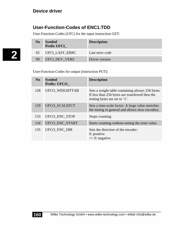
Device driver
Wilke Technology GmbH • www.wilke-technology.com • eMail: [email protected]
2
160
User-Function-Codes of ENC1.TDDUser-Function-Codes (UFC) for the input instruction GET:
No SymbolPrefix UFCI_
Description
65 UFCI_LAST_ERRC Last error code
99 UFCI_DEV_VERS Driver version
User-Function-Codes for output (instruction PUT):
No SymbolPrefix: UFCO_
Description
128 UFCO_WEIGHTTAB Sets a weight table containing always 256 bytes.If less than 256 bytes are transferred then theresting bytes are set to ‘1’.
129 UFCO_SCALEFCT Sets a time-scale factor. A large value stretchesthe timing in general and allows slow encoders.
133 UFCO_ENC_STOP Stops counting
134 UFCO_ENC_START Starts counting without setting the reset value.
135 UFCO_ENC_DIR Sets the direction of the encoder:0: positive<> 0: negative
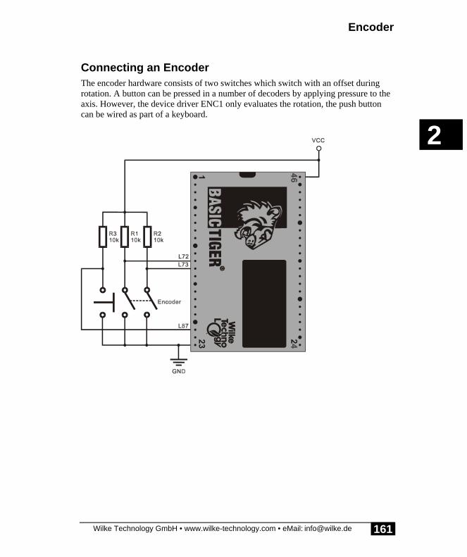
Encoder
Wilke Technology GmbH • www.wilke-technology.com • eMail: [email protected]
2
161
Connecting an EncoderThe encoder hardware consists of two switches which switch with an offset duringrotation. A button can be pressed in a number of decoders by applying pressure to theaxis. However, the device driver ENC1 only evaluates the rotation, the push buttoncan be wired as part of a keyboard.

Device driver
Wilke Technology GmbH • www.wilke-technology.com • eMail: [email protected]
2
162
Program example:
'--------------------------------------------------------------------'Name: ENC1.TIG'--------------------------------------------------------------------#INCLUDE UFUNC3.INC 'User Function definitionsTASK Main 'begin task MAIN LONG P'install LCD-driver (BASIC-Tiger) INSTALL DEVICE #1, "LCD1.TDD"'install LCD-driver (TINY-Tiger)'INSTALL DEVICE #1, "LCD1.TDD", 0, 0, 0, 0, 0, 0, 80h, 8 INSTALL_DEVICE #2, "TIMERA.TDD",1,250 'time base 10kHz INSTALL_DEVICE #3, "ENC1_801.TDD" 'install encoder driver
PRINT #1, "<1>Encoder on L80/81" PUT #3, 0 'start encoder LOOP 999999999 'many loops GET #3, #0, 4, P 'read encoder position PRINT_USING #1, "<1BH>A<0><1><0F0H>Encoder:";P;" "; WAIT_DURATION 100 ENDLOOPEND 'end task MAIN
Dynamic counterThe first example program shows how to read the steps the encoder really has done.However, it is not easy to adjust large numbers with the encoder. Large steps shouldbe done to roughly approach the desired value, actually count more than the encoderreally does, then count every step to fine adjust the value. Without dynamic readingmany rotations must be done to change a large number.
Dynamic reading means that one physical step of the encoder is translated into morelogical steps. The higher the speed of the physical steps the more dynamic the logicalsteps are. In order to adapt a slower encoder to the dynamic reading, the long step-timing of the slow encoder is divided by a factor, so that the timing values are withinthe range of the dynamic time table.

Encoder
Wilke Technology GmbH • www.wilke-technology.com • eMail: [email protected]
2
163
Adaptation of an encoder is a matter of testing and ‘feeling’. Mechanical factors likesize and style of the knob play a role. The following table shows the timings for 2different encoders which are manipulated by hand. The encoder with only 6 steps perrotation needs for one fast step more time than the fine encoder for a slow step. Thedivider factor brings the slow timing into the right range:
few pulses(6/revolution)
many pulses(180/revolution)
fast 3 R/sec = 55.5 ms per step 3 R/sec = 1.8 ms per step
medium 1 R/sec = 167 ms per step 1 R/sec = 5.6 ms per step
slow 1/6 R/sec = 1000 ms per step 1/6 R/sec = 33.3 ms per step
Divider 10 1
fast 3 R/sec = 2,5 (10)ticks per step see above
medium 1 R/sec = 16,7 (10)ticks per step see above
slow 1/6 R/sec = 100 (10)ticks per step see above
The device driver uses a standard table made for an encoder with 30 steps. Thisencoder is on the BASIC-Tiger® Graphic Toolkit. You may use this table a basis foryour own encoder. As the internal table contains 256 bytes the rest of the table isfilled with ‘1’ bytes.:
WGHT$ = &64 64 64 64 64 64 32 28 18 10 08 04 04 04 04 03&03 03 03 03 03 03 02 02 02 02 02 02 02 02 02 02"%

Device driver
Wilke Technology GmbH • www.wilke-technology.com • eMail: [email protected]
2
164
The example program runs on the Plug & Play Lab. A further impressive example isENC_WEIGHT.TIG in the subdirectory LCD-Kit. For this example you need agraphic LCD as a display.
Program example:
'--------------------------------------------------------------------'Name: ENC1_WGHT.TIG'Demonstrates the dynamic-function of the encoder driver'With higher rotating speed the driver'counts in higher steps.'Also shown: Speed-Index values.'for graphic LCD see also ENC_WEIGHT.TIG in subdirectory LCD-Kit'--------------------------------------------------------------------user_var_strict 'variables must be declared#include DEFINE_A.INC 'general defines#include UFUNC3.INC 'definitions of user function codes
TASK MAIN LONG dwEnc, dwEnc_DYN, SPEED_NDX LONG N, SPEED REAL SPEED_REAL STRING DYN_WEIGHT$ (256) 't table for dynamic steps
'install LCD-driver (BASIC-Tiger) install_device #LCD, "LCD1.TDD"'install LCD-driver (TINY-Tiger)'INSTALL DEVICE #1, "LCD1.TDD", 0, 0, 0, 0, 0, 0, 80h, 8 install_device #TA, "TIMERA.TDD",3,156 'time base 1kHz install_device #ENC, "ENC1_801.TDD" 'Encoder driver PUT #LCD, "<1bh>c<0><0f0h>" 'cursor off PRINT #LCD, "<1>Encoder on L80/81" DYN_WEIGHT$ = "& 'init weight table64 64 64 64 64 64 32 28 18 10 08 04 04 04 04 03&03 03 03 03 03 03 02 02 02 02 02 02 02 02 02 02"% put #ENC, #0, #UFCO_WEIGHTTAB, DYN_WEIGHT$ 'dynamic weight table put #ENC, #0, #UFCO_ENC_DIR, 1 'set counting direction = NEGATIVE put #ENC, 0 'start encoder counting
while 0 = 0 'endless loop get #ENC, #0, 4, dwEnc 'read STATIC turned steps get #ENC, #2, 4, dwEnc_DYN 'read DYNAMIC turned steps get #ENC, #6, 4, SPEED_NDX 'read Speed-Index: 00...FF SPEED_REAL = LOG (256000.0/(SPEED_NDX+1)) SPEED = INT (110*(SPEED_REAL-3)) print #LCD, "<1Bh>A<0><1><0F0h>Steps:";dwEnc;" "; print #LCD, "<1Bh>A<0><2><0F0h> dyn.:";dwEnc_DYN;" "; print #LCD, "<1Bh>A<0><3><0F0h>Speed:";SPEED;" "; wait_duration 100 'd endwhileEND

Frequency meter
Wilke Technology GmbH • www.wilke-technology.com • eMail: [email protected]
2
165
Frequency meterThis device driver measures the frequency at a pin by evaluating the pulse lengths(high and low). The special mode of operation means a high accuracy at a low gatetime, particularly at low frequencies. The file name of the device driver determineswhich pins are used to measure the frequency during installation of the driver. Themaximum recordable frequency is determined by the TIMERA setting t.
File name: FREQ1_Pp.TDD
INSTALL DEVICE #D, "FREQ1_Pp.TDD", P1
D is a constant, variable or expression of the data type BYTE,WORD, LONG in the range from 0...63 and stands for thedevice number of the driver.
Ppp in the file name stands for:P: internal portp: measuring pin.
P1 Triggering with0: rising flank1: falling flank2: next flank
The measurement is started by sending the desired number of measurements to thedriver with a PUT instruction:
PUT #D, Number
The driver FREQ1 initially waits for the next suitable flank. The maximum number ofmeasurements specified in Number are then performed. TIMERA specifies when themeasuring pin is controlled with the pre-set time-slot pattern. Each change of flank atthe pin triggers a measurement.
Note: If the TIMERA frequency is altered during measurements this produces valueswhich are no longer reconstructable.�

Device driver
Wilke Technology GmbH • www.wilke-technology.com • eMail: [email protected]
2
166
User-Function-Codes for input (instruction GET):
No SymbolPrefix: UFCI_
Description
1 UFCI_IBU_FILL Capacity of input buffer (Byte)
2 UFCI_IBU_FREE Free space in input buffer (Byte)
3 UFCI_IBU_VOL Size of input buffer (Byte)
65 UFCI_LAST_ERRC Last Error-Code
99 UFCI_DEV_VERS Driver version
User-Function-Codes for output (instruction PUT):
No SymbolPrefix: UFCO_
Description
1 UFCO_IBU_ERASE Delete input buffer
129 UFCO_FRQ_GATE Set gate time to max. meas. time (6...65535)
131 UFCO_FRQ_EDGE Sets the trigger flank to start measurement:0: rising flank1: falling flank2: next flank
134 UFCO_FRQ_CAL Sets the calibration factor
149 UFCO_FRQ_STOP Stops the measurement
The command UFCO_FRQ_GATE is used to set the maximum measuring time inTIMERA units. The measuring pin is monitored and flanks registered during thisperiod. The real measuring time is always equal to or less than this gate time.
Frequency meter
Wilke Technology GmbH • www.wilke-technology.com • eMail: [email protected]
2
167
The frequency device driver provides the results of the measurement at varioussecondary addresses in different units:
Sec.-Addr.
Read operation
0 Result in mHz (=1/1000Hz)
1 Result as average period length in µsec
A calibration factor can be entered to compensate quartz inaccuracies in the module.The value 65536=10000H has the same meaning 100%, i.e. if this value is specifiedas the calibration factor the measured value is output unchanged. Deviations up ordown can be corrected accordingly in steps of 1/65536.

Device driver
Wilke Technology GmbH • www.wilke-technology.com • eMail: [email protected]
2
168
Program example:
#INCLUDE UFUNC3.INCTASK Main LONG F
INSTALL DEVICE #1, "LCD1.TDD"
INSTALL_DEVICE #2, "TIMERA.TDD",1,200 INSTALL_DEVICE #3, "FREQ1_80.TDD",0
GET #3, #0, #UFCI_IBU_VOL, 0, VOL PRINT #1, "buffer size:";VOL WAIT_DURATION 3000
PRINT #1, "<1>Frequency on L80" PUT #3,#0,#UFCO_FRQ_GATE, 5000 PUT #3, 0 LOOP 999999999 GET #3,#0,#UFCI_IBU_FILL,0,FILLING IF FILLING > 0 THEN GET #3, #0, 4, F USING "UD<7><1> 3,3,3,3.3" PRINT_USING #1, "<1BH>A<0><2><0F0H> freq0:";F;" "; GET #3,#0,#UFCI_IBU_FILL,0,FILLING WHILE FILLING = 0 GET #3,#0,#UFCI_IBU_FILL,0,FILLING ENDWHILE GET #3, #1, 4, F F = F / 10 USING "UD<7><1> 3,3,3,3.3" PRINT_USING #1, "<1BH>A<0><3><0F0H>period:";F;"msec"; ENDIF ENDLOOPEND

Measure pulse lengths with high resolution
Wilke Technology GmbH • www.wilke-technology.com • eMail: [email protected]
2
169
Measure pulse lengths with high resolutionThe device driver ‘PLSIN1’ measures the length of high pulses at a resolution of up to0.4 µsec and writes the value to a buffer so that pulses in quick succession can berecorded. The measuring area is specified during installation of the driver. However,the area can also be altered at a later time through commands to the driver.
File name: PLSIN1.TDD
INSTALL DEVICE #D, "PLSIN1.TDD", Area
D is a constant, variable or expression of the data type BYTE,WORD, LONG in the range from 0...63 and stands for thedevice number of the driver.
Area is a parameter to determine the area.
Area Timebase Resolution Time area
1 2.500.000 kHz 0.400 µsec 0.0004...26.214 msec
2 625.000 kHz 1.600 µsec 0.0016...104.856 msec
3 156.250 kHz 6.400 µsec 0.0064...419.424 msec
Secondary address 0 selects the channel 0 of the pulse-in-device driver. The input pinis always Pin L84.
The device driver PLSIN1 measures very short pulses at resolutions down to 0.4µsecand hereby uses hardware resources of the BASIC-Tiger® or Tiny-Tiger® module.Since other fast drivers may also need these hardware resources, the simultaneous useof a number of drivers is excluded.
Possible uses of the driver PLSIN1.TDD together with PLSOUT1.TDD in BASIC-Tiger® and Tiny-Tiger® modules
PLSOUT1 PLSIN1
1 channel —
— 1 channel
The incoming measured values are buffered in a 256 Byte buffer. The measuredvalues are WORD, so that 128 values with a maximum pulse length of 65535 units

Device driver
Wilke Technology GmbH • www.wilke-technology.com • eMail: [email protected]
2
170
can be saved. One unit is identical with the resolution of the area, e.g. 1.6 µsec inarea 2. The buffer statuses and any errors can be inquired with ‘USER-FUNCTION-CODEs’, or ‘UFC’ for short.
Example: read a pulse length measured value from the buffer:
GET #11, 2, wVar
User-Function-Codes for input (instruction GET):
No Symbol Description
1 UFCI_IBU_FILL Capacity of input buffer (Byte)
2 UFCI_IBU_FREE Free space in input buffer (Byte)
3 UFCI_IBU_VOL Size of input buffer (Byte)
65 UFCI_LAST_ERRC Last Error-Code
99 UFCI_DEV_VERS Driver version
160 UFCI_IPL_OVL Number of buffer overflows since this counterwas last read.Resets counter to 0.
User-Function-Codes for output (instruction PUT):
No SymbolPrefix: UFCO_
Description
1 UFCO_IBU_ERASE Delete input buffer
128 UFCO_IPL_RNG Set area
Example: inquire version number of driver:
GET #11,#0, #UFCI_DEV_VERS, 2, wVersion

Measure pulse lengths with high resolution
Wilke Technology GmbH • www.wilke-technology.com • eMail: [email protected]
2
171
Example: set area 2:
PUT #11,#0, #UFCO_IPL_RNG, 2
Example: inquire full level of pulse length buffer. The command ‘UFCI_IBU_FILL’is a byte, but the read reply from the driver is at least a WORD-number:
GET #11,#0, #UFCI_IBU_FILL, 2, wVar

Device driver
Wilke Technology GmbH • www.wilke-technology.com • eMail: [email protected]
2
172
Program example:
'--------------------------------------------------------------------'Name: PLSIN1.TIG'--------------------------------------------------------------------#INCLUDE UFUNC3.INC 'Define User Function Codes
TASK MAIN 'begin task MAIN WORD I, PLEN'install LCD driver (BASIC-Tiger) INSTALL DEVICE #1, "LCD1.TDD"'install LCD driver (TINY-Tiger)'INSTALL DEVICE #1, "LCD1.TDD", 0, 0, 0, 0, 0, 0, 80h, 8 INSTALL DEVICE #8, "PLS1IN.TDD", 1 '1 = range
PRINT #1, "connect pin L80" 'connect pin L80 PRINT #1, " with pin L84" 'with pin L84 OUT 8, 00000001b, 0 'Pin L80 low DIR_PIN 8, 0, 0 'Pin L80 output
PUT #8,#0, #UFCO_IPL_RNG, 1 'range 1 WAIT_DURATION 1000 OUT 8, 00000001b, 1 '1 pulse on pin L80 OUT 8, 00000001b, 0 GET #8, 2, PLEN 'reads 0 if no pulse PRINT #1, "<1>Pulse length:" PRINT #1, PLEN;" *0.4microsec"
PUT #8,#0, #UFCO_IPL_RNG, 2 'range 2 WAIT_DURATION 1000 OUT 8, 00000001b, 1 '1 pulse on pin L80 OUT 8, 00000001b, 0 GET #8, 2, PLEN 'reads 0 if no pulse PRINT #1, PLEN;" *1.6microsec"
PUT #8,#0, #UFCO_IPL_RNG, 3 'range 3 WAIT_DURATION 1000 OUT 8, 00000001b, 1 '1 pulse on pin L80 OUT 8, 00000001b, 0 GET #8, 2, PLEN 'reads 0 if no pulse PRINT #1, PLEN;" *6.4microsec"END 'End Task MAIN

Measure pulse lengths with TIMERA
Wilke Technology GmbH • www.wilke-technology.com • eMail: [email protected]
2
173
Measure pulse lengths with TIMERAThis device driver measures the pulse length (high and low) at a pin. The file namegiven during installation of the driver specifies the pins at which the pulse lengthmeasurement is to take place. The resolution is determined by the TIMERA setting.
File name: PLSI2_Pp.TDD
INSTALL DEVICE #D, "PLSI2_Pp.TDD", P1, P2
D is a constant, variable or expression of the data type BYTE,WORD, LONG in the range from 0...63 and stands for thedevice number of the driver.
Ppp in the file name stands for:P: internal portp: measuring pin.
P1 is a parameter which sets the measurement to 16 or 32 bit32: sets a 32-bit measurementany other or smaller value sets a 16-bit measurement.
P2 is a parameter which automatically extends the sign fromWORD to LONG in a 16-bit measurement.0: sign is extended1: sign not extended
The measurement is started by transferring a value to the driver with a PUTinstruction. The transferred value determines the action of the driver:
Value Read operation
0 Stops the measurement
1 Starts the measurement with the next flank
2 Starts the measurement with the next rising flank
3 Starts the measurement with the next falling flank
Once the measurement has started PLSI2 waits for the matching flank in the cycled ofthe TIMERA ticks. Once the flank has arrived the measurement is carried out in timeunits specified by TIMERA. The 'high' part of the pulse is saved as positive number in

Device driver
Wilke Technology GmbH • www.wilke-technology.com • eMail: [email protected]
2
174
the buffer, the 'low' part as a negative number. The measurement is stopped when thebuffer is full or when a stop command is sent.
A 16-bit measurement has certain advantages:
• Lower load on the CPU.• The buffer can hold more measured values.
Since WORD variables have no sign the measured values should be read out with aLONG variable. The driver automatically adds the appropriate sign from WORD toLONG. If the measured value were to be read out with WORD variables or theautomatic sign extension deactivated all measured values for the 'low' part of the pulse65536 would be minus the measured time.
Note: If the TIMERA frequency is altered during measurements this produces valueswhich are no longer reconstructable.
User-Function-Codes for input (instruction GET):
No SymbolPrefix: UFCI_
Description
1 UFCI_IBU_FILL Capacity of input buffer (Byte)
2 UFCI_IBU_FREE Free space in input buffer (Byte)
3 UFCI_IBU_VOL Size of input buffer (Byte)
65 UFCI_LAST_ERRC Last Error-Code
99 UFCI_DEV_VERS Driver version
�

Measure pulse lengths with TIMERA
Wilke Technology GmbH • www.wilke-technology.com • eMail: [email protected]
2
175
User-Function-Codes for output (instruction PUT):
No SymbolPrefix: UFCO_
Description
1 UFCO_IBU_ERASE Delete input buffer
128 UFCO_PLS_SIGN 0: 16-bit values are evaluated with sign (-32767...+32768)1: 16-bit values are evaluated without sign(0...65535)
133 UFCO_PLS_STOP Stops the measurement
Program example:
'--------------------------------------------------------------------'Name: PLSI2.TIG'--------------------------------------------------------------------user_var_strict#include define_a.inc#include UFUNC3.INCTASK Main 'begin task MAINLONG FILLING, F'install LCD-driver (BASIC-Tiger) INSTALL DEVICE #1, "LCD1.TDD"'install LCD-driver (TINY-Tiger)'INSTALL DEVICE #1, "LCD1.TDD", 0, 0, 0, 0, 0, 0, 80h, 8 INSTALL_DEVICE #2, "TIMERA.TDD",1,250 'time base 10kHz INSTALL_DEVICE #3, "PLSI2_80.TDD",0 'install pulse length measurement INSTALL DEVICE #4, "SER1B_K1.TDD", BD_19_200, DP_8N, YES, BD_19_200,DP_8N, YES USING "UD<8><1> 3,3,3,3.3" 'set decimal point at /1000
PRINT #1, "<1>pulses on L80"; run_task disp'0 = stop measurement immediately'1 = start measurement with next edge'2 = start measurement with next rising edge'3 = start measurement with next falling edge PUT #3, 2 'start at next edge LOOP 999999999 'many loops GET #3,#0,#UFCI_IBU_FILL,0,FILLING 'if results are in the buffer IF FILLING > 1 THEN GET #3, #0, 4, F 'read result in mHz F = ABS(F) PRINT_USING #1, "<1BH>A<0><2><0F0H>plsl0 L80:";F; PRINT_USING #4, "plsl0:";F;"<9>"; GET #3, #0, 4, F 'read result in mHz F = ABS(F)

Device driver
Wilke Technology GmbH • www.wilke-technology.com • eMail: [email protected]
2
176
PRINT_USING #1, "<1BH>A<0><3><0F0H>plsl1 L80:";F; PRINT_USING #4, "plsl1:";F PUT #3, #0, #UFCO_IBU_ERASE, 0 'ase buffer PUT #3, 2 'ing edge WAIT_DURATION 10 ENDIF ENDLOOPEND 'end task MAIN
TASK disp BYTE i LONG f
for i = 0 to 0 step 0 get #3, #0, #UFCI_IBU_FILL, 0, f print #1, "<1bh>A<0><1><0f0h>fill: ";f;" "; wait_duration 100 nextEND
Output pulse with high resolution
Wilke Technology GmbH • www.wilke-technology.com • eMail: [email protected]
2
177
Output pulse with high resolutionThe device driver ‘PLSOUT1’ is able to generate pulses with a resolution of up to0.4 µsec. The area is determined during installation of the driver. However, the areacan also be altered at a later time through commands to the driver.
File name: PLSOUT1.TDD
INSTALL DEVICE #D, "PLSOUT1.TDD", Area
D is a constant, variable or expression of the data type BYTE,WORD, LONG in the range from 0...63 and stands for thedevice number of the driver.
Area is a parameter to determine the area.
Area Timers Resolution Time area
1 2.500.000 kHz 0.400 µsec 0.0004...26.214 sec
2 625.000 kHz 1.600 µsec 0.0016...104.856 sec
3 156.250 kHz 6.400 µsec 0.0064...419.424 sec
Secondary address 0 selects the channel 0 of the pulse-out-device driver. The possiblenumber of channels depends on the module In BASIC-Tiger® or Tiny-Tiger® modulesversion 1.0xx only this channel is available. The input pin is always Pin L86.
The device driver PLSOUT1 enables a very fast pulse output up to 1.25 MHz herebyuses hardware resources of the BASIC-Tiger® or Tiny-Tiger® module. Since otherfast drivers may also need these hardware resources, the simultaneous use of anumber of drivers is excluded.
Possible uses of the driver PLSOUT1.TDD together with PLSIN1.TDD in BASIC-Tiger® and Tiny-Tiger® modules
PLSOUT1 PLSIN1
1 channel —
— 1 channel

Device driver
Wilke Technology GmbH • www.wilke-technology.com • eMail: [email protected]
2
178
Pulse output:
PUT #D, #0, cnt, duty, cycle
D is a constant, variable or expression of the data type BYTE,WORD, LONG in the range from 0...63 and stands for thedevice number of the driver.
cnt is a constant, variable or expression of the data type LONG andspecifies the number of pulses to be output.
duty is a constant, variable or expression of the data type WORD inthe range from 0...65535 and specifies the time in units of theset area for which the pulse should be ‘low’.
cycle is a constant, variable or expression of the data type WORD inthe range from 0...65535 and specifies the total time of a pulsein units of the set area.
Attention: this device driver needs variables of the above given type: LONG for cnt,and WORD for cycle and duty.
When counting pulses then the current Tiger modules are restricted to the followingvalues of CYCLE and DUTY: CYCLE, range-1 min. 32, range-2 min. 8, range-3 min. 3 DUTY, range-1 min. 31, range-2 min. 7, range-3 min. 2 Smaller values with COUNT <> 0 will cause a runtime error.
User-Function-Codes of PLSOUT1.TDDUser-Function-Codes for input (instruction GET):
No SymbolPrefix: UFCI_
Description
176 UFCI_OPL_STAT read current Count-Down value0: last pulse just finishingn: n complete pulses follow-1: already at a standstill

Output pulse with high resolution
Wilke Technology GmbH • www.wilke-technology.com • eMail: [email protected]
2
179
User-Function-Codes for the device drivers PLSOUT1 for output are defined in theInclude-File ‘UFUNCn.INC’ (instruction PUT):
No Symbol Description
144 UFCO_OPL_RNG set area
145 UFCO_OPL_CNT set new number of pulses
Example: (area: 3) output 10 pulses with the cycle time 32µsec (5*6.4µsec) and theLow-Time of 12.8µsec (2* 6.4µsec):
PUT #10, #0, 10, 2, 5
Example: Set area 2 during the runtime:
PUT #10,#0, #UFCO_OPL_RNG, 2
Example: read the number of pulses following the pulse which is currently running:
GET #10,#0, #UFCI_OPL_STAT, 4, CNT
Example: with running, possibly infinite pulse output, set the new number of pulsesto 1. The output can thus be aborted, whereby the scanning rate and the frequency areretained, the last pulse is still completely output:
PUT #10,#0, #UFCO_OPL_CNT, 1
As an example of an application for the device driver PLSOUT1.TDD you will find aprogram in the sub-directory APPLICAT which outputs a melody via the output pin:PO_JUKEB.TIG.

Device driver
Wilke Technology GmbH • www.wilke-technology.com • eMail: [email protected]
2
180
Program example:
'--------------------------------------------------------------------'Name: PLSOUT1.TIG'--------------------------------------------------------------------#INCLUDE UFUNC3.INC
TASK MAIN WORD I, DUTY LONG CYCLE LONG N, COUNT INSTALL_DEVICE #9, "PLSOUT1.TDD", 3 'Time base range = 3
COUNT = 1 '1 pulse with length CYCLE = 20 '20x 6,4usec = 128usec DUTY = 10 'duty 50% PUT #9, COUNT, DUTY, CYCLE 'pulse output on pin 86
COUNT = 3 'one long pulse 'program waits for its end CYCLE = 65534 '0.42 sec DUTY = 32767 'duty 50% PUT #9, COUNT, DUTY, CYCLE 'pulse output on pin 86 'count down ends FOR N=999999999 TO 0 STEP -1 'when N=0 is read GET #9,#0,#UFCI_OPL_STAT, 4, N 'read count down NEXT
COUNT = 200 '200pulses of length CYCLE = 360 '360x 6,4usec = 2,3msec DUTY = 18 'duty 5% PUT #9, COUNT, DUTY, CYCLE 'pulse output on pin 86 'count down ends FOR N=999999999 TO 0 STEP -1 'when N=0 is read GET #9,#0,#UFCI_OPL_STAT, 4, N 'read count down NEXTEND

Output pulse with TIMERA
Wilke Technology GmbH • www.wilke-technology.com • eMail: [email protected]
2
181
Output pulse with TIMERAThis device driver outputs pulses to a pin whose overall time (Cycle) and 'high'-share(Duty) can be adjusted. During installation of the driver the file name specifies the pinat which the pulses are to be output. The resolution is determined by the TIMERAsetting.
Further information on PLSO2_xx.TDD
• Secondary addresses of PLSO2_xx.TDD• User-Function-Codes of PLSO2_xx.TDD
File name: PLSO2_Pp.TDD
INSTALL DEVICE #D, "PLSO2_Pp.TDD", P1, P2
D is a constant, variable or expression of the data type BYTE,WORD, LONG in the range from 0...63 and stands for thedevice number of the driver.
Ppp in the file name stands for:P: internal portp: measuring pin.
P1 is a parameter which sets the inactive level.
TIMERA.TDD must be installed before PLSO2_xx.TDD.
The pulse output is started by transferring the values 'Number of pulses', Cycle andDuty to the driver with a PUT instruction.
PUT #D, cnt, duty, cycle
cnt is a constant, variable or expression of the data type BYTE,WORD, LONG in the range from 0...63 and stands for thedevice number of the driver.cnt=0 means; infinite.
duty is a constant, variable or expression of the data type BYTE,WORD, LONG in the range from 0...65535 and specifies thetime in units of the set area for which the pulse should be‘high’. 'duty' is always smaller than 'cycle'.

Device driver
Wilke Technology GmbH • www.wilke-technology.com • eMail: [email protected]
2
182
cycle is a constant, variable or expression of the data type BYTE,WORD, LONG in the range from 0...65535 and specifies thetotal time of a pulse in units of the set area.
Values written to the secondary address are 'Reload values' which are taken overdirectly when the current pulses are output. Example:
PUT #D, cnt, duty, cycle ' start puls outputPUT #D, #1, cnt1, duty1, cycle1 ' set values for next pulses
Secondary addresses of PLSO2_xx.TDDThe following information can be read at different secondary addresses of the driver:
Secondary Addr. Information
0 how many pulses still have to be output (without reload)
1 how many pulses still have to be output acc. to reload
2 how many pulses still have to be output (with reload)
User-Function-Codes of PLSO2_xx.TDDUser-Function-Codes for input (instruction GET):
No SymbolPrefix: UFCI_
Description
65 UFCI_LAST_ERRC Last Error-Code
99 UFCI_DEV_VERS Driver version
147 UFCI_PO2_REST Supplies the number of pulses still to be output.2147483647 (7FFFFFFF) is reset for infinite.
Example: read number of pulses still to be output:
GET #10,#0, #UFCI_OPL_REST, 0, varREST

Output pulse with TIMERA
Wilke Technology GmbH • www.wilke-technology.com • eMail: [email protected]
2
183
User-Function-Codes for output (instruction PUT):
No SymbolPrefix: UFCO_
Description
128 UFCO_PO2_LEVEL Sets the resting level at the pulse output pin
133 UFCO_PO2_STOP Stops the pulse output0: immediately (level not specified)1: with next 'high' level2: with next 'low' level
134 UFCO_PO2_ADJ Sets a new number during pulse output anddeletes the Reload- buffer.This allows an immediate stop.
Example: set new values for Number, Duty, Cycle during current pulse output:
PUT #10,#0, #UFCO_OPL_ADJ, cnt, duty, cycle

Device driver
Wilke Technology GmbH • www.wilke-technology.com • eMail: [email protected]
2
184
Program example:
'--------------------------------------------------------------------'Name: PLSO2.TIG'--------------------------------------------------------------------#INCLUDE UFUNC3.INC
TASK MAIN LONG REST, REST0, REST1, REST2
'install LCD-driver (BASIC-Tiger) INSTALL DEVICE #1, "LCD1.TDD"'install LCD-driver (TINY-Tiger)'INSTALL DEVICE #1, "LCD1.TDD", 0, 0, 0, 0, 0, 0, 80h, 8 INSTALL_DEVICE #13, "TIMERA.TDD", 1,250 '10 kHz INSTALL_DEVICE #20, "PLSO2_80.TDD" 'pulses on pin L80
PUT #20, 400, 12, 24 '400 pulses 2,4microsec cycle 'into reload buffer: PUT #20, #1, 800, 6, 12 '800 pulses 1,2microsec cycle
GET #20, #2, 4, REST2 'total no. of pulses WHILE REST2 > 0 GET #20, #0, #UFCI_OPL_REST, 4, REST'pulses still to be output GET #20, #0, 4, REST0 'outputting now GET #20, #1, 4, REST1 'are in reload GET #20, #2, 4, REST2 'total, same as UFCI_OPL_REST PRINT #1, "<1BH>A<0><0><0F0H>";REST;" total pulses";" "; PRINT #1, "<1BH>A<0><1><0F0H>";REST0;" pulses";" "; PRINT #1, "<1BH>A<0><2><0F0H>";REST1;" reload pulses";" "; PRINT #1, "<1BH>A<0><3><0F0H>";REST2;" total pulses";" "; ENDWHILE 'READYEND
See also: Application STEPPER.TIG

PWM1 (Pulse width modulation)
Wilke Technology GmbH • www.wilke-technology.com • eMail: [email protected]
2
185
PWM1 (Pulse width modulation)File name: PWM1.TDD
INSTALL DEVICE #D, "PWM1.TDD" [, f0, r0, f1, r1 ]
D is a constant, variable or expression of the data type BYTE,WORD, LONG in the range from 0→63 and stands for thedevice number of the drivers.
f0, f1 specifies the frequency for channel 0:0: high frequency1: medium frequency2: low frequency
r0, r1 specifies the resolution for channel 0:0: 6-Bit1: 7-Bit2: 8-Bit
This device driver enables pulse width modulated analog output on 2 pins of BASIC-Tiger® or Tiny-Tiger® using the instruction PUT.
Function Pin Module-APin No.
Tiny-TigerPin No.
PWM channel 0 L72 12 11
PWM channel 1 L73 13 12
The channel number is specified by secondary address given in the output instruction.At resolution of 8 bit values from 0→255 are output at the respective PWM-output. Avalue directed to a PWM output will be retained there until a new value is set. Atresolution of 7 bit values from 0→127 are possible, at 6 bit values from 0→63.

Device driver
Wilke Technology GmbH • www.wilke-technology.com • eMail: [email protected]
2
186
In the include file UFUNCn.INC symbols are defined for frequencies and resolution.The following table shows the relationship between frequency and resolution(approximate values). Default setting is 8-bit, 20kHz:
Frequency 6-Bit 7-Bit 8-Bit
High 80kHz 40kHz 20kHz
Medium 20kHz 10kHz 5kHz
Low 5kHz 2.5kHz 1.25kHz
max. cycle 63 127 255
At run time further configuration of the device driver PWM1 can be made by UserFunction Codes. Using any of the User Function Codes will stop the PWM output.After changing the resolution, frequency, etc. output must be restarted.
User Function Codes for PUT:
No Symbol Description
144 UFCO_PWM_SPEED Set speed
Arguments of the command:
0 PWM_SPEED_HI High speed
1 PWM_SPEED_MED Medium speed
2 PWM_SPEED_LO Low speed
145 UFCO_PWM_RESO Set resolution
Arguments of the command:
0 PWM_RESO_6BIT 6 Bit
1 PWM_RESO_7BIT 7 Bit
2 PWM_RESO_8BIT 8 Bit

PWM1 (Pulse width modulation)
Wilke Technology GmbH • www.wilke-technology.com • eMail: [email protected]
2
187
The frequency of PWM1 can be requested by User Function Codes at run time:
No Symbol Description
144 UFCI_PWM_FREQU Query current frequency
Response of the driver:
0 PWM_FREQU_HI See speed table
1 PWM_FREQU_MED See speed table
2 PWM_FREQU_LO See speed table
Program example:
'--------------------------------------------------------------------'Name: PWM1.TIG'--------------------------------------------------------------------TASK MAIN 'begin task MAIN REAL PI, W 'vars of type REAL LONG I, P 'vars of type LONG'install LCD-driver (BASIC-Tiger) INSTALL DEVICE #1, "LCD1.TDD"'install LCD-driver (TINY-Tiger)'INSTALL DEVICE #1, "LCD1.TDD", 0, 0, 0, 0, 0, 0, 80h, 8 INSTALL_DEVICE #6, "PWM1.TDD" 'install PWM-driver
PI = 3.14159265359 'set PI PRINT #1, "PWM-Test an Pin L72" 'output to LC-display LOOP 9999999 'many loops FOR I = 0 TO 360 STEP 5 'loop from 0 to 360 W = I * PI / 180 'deg. --> rad. P = 100 + 90 * SIN (W) 'convert to LONG PUT #6, #0, P 'PWM-output to channel 0 NEXT 'next value ENDLOOPEND 'end task MAIN

Device driver
Wilke Technology GmbH • www.wilke-technology.com • eMail: [email protected]
2
188
Empty Page

PWM2 (Pulse width modulation)
Wilke Technology GmbH • www.wilke-technology.com • eMail: [email protected]
2
189
PWM2 (Pulse width modulation)This device driver allows time synchroneous output of pulse width modulated analogvalues. It can be used to output speech, music, and similar fast analog curves.
Further information on PWM2.TDD:
• PWM output• User-Function-Codes of PWM2.TDD• Setting the Output-rate• Over-sampling• Using the Reload-Buffer• Sound output with PWM2
File name: PWM2.TDD
INSTALL DEVICE #D, "PWM2.TDD" [, Ch, Reso, Frq, Ovs, decof, sh, PS ]
D is a constant, variable or expression of type BYTE, WORD,LONG in the range from 0 to 63 and acts as the driver‘s devicenumber.
Ch is a parameter to select the channel (0 or 1)
Reso is a parameter to select the resolution:0: 6-Bit1: 7-Bit2: 8-Bit
Frq is a parameter to select the PWM carrier frequency:0: high1: medium2: low
Ovs is a parameter to select over-sampling:1: no over-samplingn=2...255: Number (n-1) of intermediate values that will begeneratedNote: Over-sampling is ______________
decof is a parameter to select the decoding-flag:0: No Decoding

Device driver
Wilke Technology GmbH • www.wilke-technology.com • eMail: [email protected]
2
190
Currently, only 0 can be used for this parameter value.Note: Decoding flag refers to ______________
sh is a parameter to select Downshift:0: no Downshift1: one Downshift (7-bit)2: two Downshifts (6-bit).Note: Decoding flag refers to ______________
PS is a parameter to select the pre-scalers:0,1: no Pre-Scaler2...65535: Pre-scaler ‘s divisor.
The Device Driver PWM2.TDD outputs the values from a String as a PWM-Signal.(PWM = Pulse-Width-Modulation). Output is synchronized using driver‘TIMERA.TDD’, yielding high performance independent of the BASIC program. TheTIMER driver provides a base-frequency which is divided by the PWM’s pre-scalerto yield the actual output rate. The driver is configured during installation, subsequentchanges can be made through User Function Codes.
The output-data is contained byte-wise in the string.
The output-string must exist at all times ! Transient variables (e.g. local strings in sub-routines or temporary strings (expressions) must NOT be used. Instead, use Globalstrings or strings local to the Task.
The string is loaded into the PWM Driver using the PUT command with secondaryaddress 0. The bytes appear in the selected output-speed as a PW-modulated signal onthe output pin.
NOTE: The output-pin is determined by a parameter during driver-installation, not bythe secondary address !
Secondary Address 1 is used for "Reload-Data", which will be automatically output assoon as no other data is available for output. This ensures seamless transfer from onedata-string to the next. The transfer from the Reload-Buffer into the output bufferhappens at the instant that the output-buffer is empty. If the reload-buffer is loadedtoo late, it will only be transferred on the next cycle.
Using User-Function-Code UFCI_PWM_RELOAD, the BASIC-Program can query ifthe transfer already happened, and if the reload-buffer is available. If this is the case,the next data-string can be written to the secondary address.
�

PWM2 (Pulse width modulation)
Wilke Technology GmbH • www.wilke-technology.com • eMail: [email protected]
2
191
Besides an adjustable resolution and carrier frequency-range, ‘Over-sampling’ can beadjusted. Using this option, intermediate values are interpolated and output, thussmoothing the signal curve. This can also be used to keep the size of the output-data-string small.
With a PWM-Resolution of 7 or 6 Bits, the driver can automatically scale the outputvalues by shifting the bits of an 8 bit value.
PWM outputOutput is started using the following command:
PUT #D [, #Sec_Adr] Str$ [, Offs, No, Rpt, Sh_dn ]
D is a constant, variable or expression of type BYTE, WORD,LONG in the range from 0 to 63 and acts as the driver‘s devicenumber.
#Sec_Adr is a constant, variable or expression of type BYTE, WORD,LONG in the range from 0 to 63 and acts as the secondaryaddress. If omitted, sec. Address 0 is assumed. 1 addresses thereload-buffer.
Str$ is the data-string.Str$ must be static, i.e. global or local to task
Offs is a constant, variable or expression of type BYTE, WORD orLONG and determines the offset into the string from whichdata is to be output. Default is 0 (i.e. from beginning of string).
No is a constant, variable or expression of type BYTE, WORD orLONG and determines the number of bytes that is to be output.If zero is used, data is output until the end of the string.
Rpt is a constant, variable or expression of type BYTE, WORD orLONG and determines the number of repetitions. Zero =infinite repetitions.
Sh_dn is a constant, variable or expression of type BYTE, WORD orLONG and determines the number of downshifts. This is usedto adjust the effective data-size to the actual resolution (6,7,8-Bit) of the PWM Driver. Possible values are 0, 1 or 2.

Device driver
Wilke Technology GmbH • www.wilke-technology.com • eMail: [email protected]
2
192
PWM output appears on the following pin:
Function Pin Module-APin-No.
Tiny-TigerPin-No.
PWM-Channel 0 L72 12 11
PWM-Channel 1 L73 13 12
File UFUNCn.TIG, contains symbol-declarations for frequency and resolution. Theirnames and relationship between frequency and resolution is shown below (values areapprox.):
No Symbol Frequency
6-Bit 7-Bit 8-Bit
0 PWM_SPEED_HI Hi 80kHz 40kHz 20kHz
1 PWM_SPEED_MED Medium 20kHz 10kHz 5kHz
2 PWM_SPEED_LO Low 5kHz 2.5kHz 1.2kHz
After installation, driver parameters can be adjustments at run-time using additionalUser-Function-Codes.
Adjusting parameters has no effect on the current PWM output, the new parametersbecome active with the next start.
The following table gives an overview of the particular Function-Codes for thisdriver. File UFUNCn.INC must be included for the compiler to be able to recognizethem.

PWM2 (Pulse width modulation)
Wilke Technology GmbH • www.wilke-technology.com • eMail: [email protected]
2
193
User-Function-Codes of PWM2.TDDUser-Function Codes for setting parameters: PUT:
No SymbolPrefix: UFCO_
Description
46 UFCO_PWM_DFLT Reset to defaults
144 UFCO_PWM_FREQU Set PWM-Carrier Frequency (see Table)0: hi1: medium2: low
145 UFCO_PWM_RESO_ Set PWM-Resolution:6: 6-Bit7: 7-Bit8: 8-Bit
146 UFCO_PWM_PSCAL Set Pre-Scaler:0, 1: no pre-scalern: Divisor (WORD)
147 UFCO_PWM_OSAMP Over-sampling: # of intermediate values:1: none2...255: Generate n-1 Intermediate values.
154 UFCO_PWM_STOP Stop: stop output.
159 UFCO_PW2_PSCIMM Set pre-scaler immediately (without restart)

Device driver
Wilke Technology GmbH • www.wilke-technology.com • eMail: [email protected]
2
194
User-Function-Codes to query PWM2.TDD (GET):
No SymbolPrefix: UFCI_
Description
68 UFCI_CPU_LOAD Load put on CPU by this driver (100%=10.000)
144 UFCI_PWM_FREQU Actual PWM-Carrier-Frequency in Hz.(Values are approximate)
145 UFCI_PWM_ACT Output active
0: Output is taking place.0FFh: idle
146 UFCI_PWM_RELOAD Reload-Buffer state:0: emptynon-0: contains data.

PWM2 (Pulse width modulation)
Wilke Technology GmbH • www.wilke-technology.com • eMail: [email protected]
2
195
Setting the Output-rateThe output-rate is a function of the base-frequency provided by device driverTIMERA. The pre-scaler of device Driver PWM2 divides that base-frequency.
Thus, the actual output rate is calculated as:
Range-Frequency / Divisor / pre-scaler
For example, an output rate of 500 values per second is set using:
PUT #13, 2, 125 ' TIMERA Range 2, Divisor 125 = 5kHzPUT #8, #0, #UFCO_PW2_PSCAL, 10 ' Pre-Scaler divides by 10
pre-scalerof
devicedriver
range 1
divisionfactor
xxMHzrange 2
range 3
TIMERA otherdevice driver
range clock

Device driver
Wilke Technology GmbH • www.wilke-technology.com • eMail: [email protected]
2
196
The pre-scaler is adjusted using User-Function-Code UFCO_PWM2_PSCAL.
When using high speeds, this Device-driver together with driver TIMERA can placesuch a load onto the CPU so as to negatively affect other tasks. The load placed ontothe CPU by this driver can be queried using User-Function-Code‘UFCI_CPU_LOAD.Certain values that would result in system-overload will not be accepted by the driver.
NOTE: TIMERA must be installed prior to PWM2.
The output-rate must not be confused with the carrier-frequency of the PWM Signal.While various output-rates can be defined using the timer and pre-scaler, only 3different carrier-frequencies are available and these are dependent on the resolution.
Over-samplingWith PWM2.TDD, the output-rate determines the speed at which new values aretaken from the data-string. Using Interpolation, intermediate values can be generated,which are output at the selected rate, thus reducing the speed at which data is takenfrom the data-string.
n - 1 n n + 1 n + 2
PWM carrier frequ.
output rate
Output with one intermediate value:
n n + 1 n + 1 n + 2
interpolatedvalue
interpolatedvalue
�

PWM2 (Pulse width modulation)
Wilke Technology GmbH • www.wilke-technology.com • eMail: [email protected]
2
197
The following is an example with only 2 characters: 10h and 0C0h. The maximumvalue of 0FFh can be output, but the plug-and-play lab cuts this off at ca. 4V, sincethe PWM amplifier output is only capable of 4 V. Also note, that frequencies above400Hz will not be amplified by the amplifier. The example code generates an outputrate of 612 bytes per second and two output-bytes with an output swing of 306 Hz.
Program example:
'--------------------------------------------------------------------'Name: PWM2_1.TIG'--------------------------------------------------------------------USER VAR STRICT 'check var declarations#INCLUDE UFUNC3.INC 'User Function Codes#INCLUDE DEFINE_A.INC 'general symbol definitions
TASK MAIN 'begin task MAIN BYTE flag 'var of type BYTE WORD i, slen, rate 'vars of type WORD LONG rest 'var of type LONG STRING PWM$ 'var of type STRING'install LCD-driver (BASIC-Tiger) INSTALL DEVICE #LCD, "LCD1.TDD"'install LCD-driver (TINY-Tiger)'INSTALL DEVICE #1, "LCD1.TDD", 0, 0, 0, 0, 0, 0, 80h, 8 INSTALL_DEVICE #TA, "TIMERA.TDD", 3, 255 '156250/255=612Hz 'ch reso freq ovs inib sh ps INSTALL_DEVICE #PWM2, "PWM2.TDD", 0, 8, 0, 0, 0, 1, 1
PWM$ = "<10><0C0h>" 'set PWM$ slen = LEN (PWM$) 'determine length of PWM$ PRINT #LCD, "PWM2"; 'output to LCD' src$, offs, len, repeat, shift PUT #PWM2, #0, PWM$, 0, slen, 1000, 0 'start PWM2 output FOR i = 0 TO 0 STEP 0 'endless loop GET #PWM2, #0, #UFCI_PW2_REST, 4, rest 'get remaining pulses PRINT #LCD, "<1Bh>A<0><1><0F0h>Rest";rest;" "; WAIT_DURATION 100 'wait 100 ms NEXT 'end of endless loopEND 'end task MAIN
Using the Reload-BufferBelow is an example in which a sinusoidal curve with 18 points is calculated in astring. This sinusoidal curve is output continuously by virtue of the reload-buffer.With an output-rate of 122 Hz and a string-length of 18 characters, an output-frequency of 6. 7Hz is achieved.
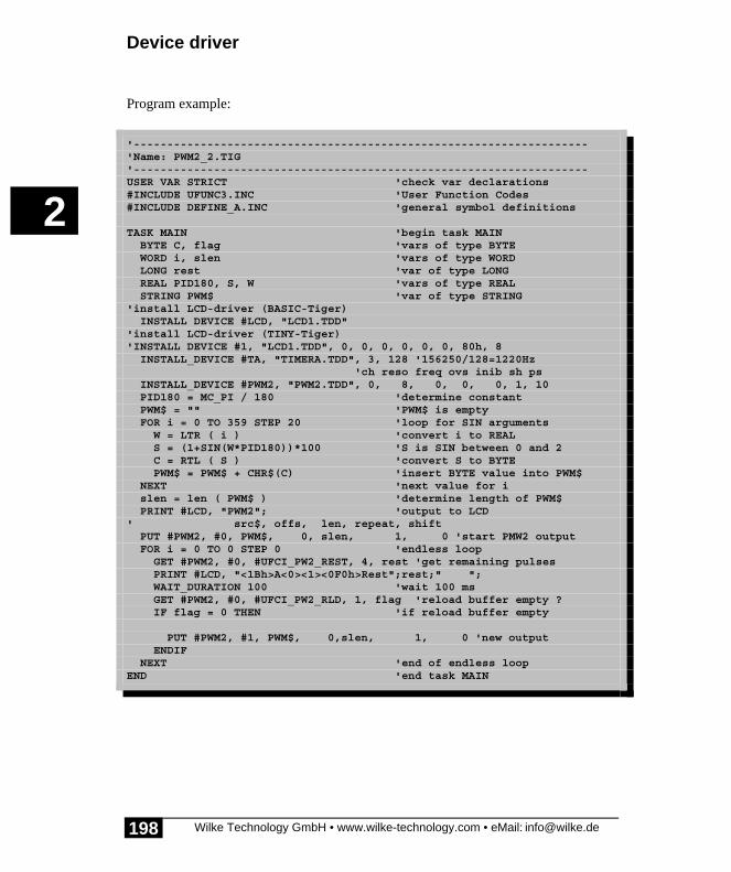
Device driver
Wilke Technology GmbH • www.wilke-technology.com • eMail: [email protected]
2
198
Program example:
'--------------------------------------------------------------------'Name: PWM2_2.TIG'--------------------------------------------------------------------USER VAR STRICT 'check var declarations#INCLUDE UFUNC3.INC 'User Function Codes#INCLUDE DEFINE_A.INC 'general symbol definitions
TASK MAIN 'begin task MAIN BYTE C, flag 'vars of type BYTE WORD i, slen 'vars of type WORD LONG rest 'var of type LONG REAL PID180, S, W 'vars of type REAL STRING PWM$ 'var of type STRING'install LCD-driver (BASIC-Tiger) INSTALL DEVICE #LCD, "LCD1.TDD"'install LCD-driver (TINY-Tiger)'INSTALL DEVICE #1, "LCD1.TDD", 0, 0, 0, 0, 0, 0, 80h, 8 INSTALL_DEVICE #TA, "TIMERA.TDD", 3, 128 '156250/128=1220Hz 'ch reso freq ovs inib sh ps INSTALL_DEVICE #PWM2, "PWM2.TDD", 0, 8, 0, 0, 0, 1, 10 PID180 = MC_PI / 180 'determine constant PWM$ = "" 'PWM$ is empty FOR i = 0 TO 359 STEP 20 'loop for SIN arguments W = LTR ( i ) 'convert i to REAL S = (1+SIN(W*PID180))*100 'S is SIN between 0 and 2 C = RTL ( S ) 'convert S to BYTE PWM$ = PWM$ + CHR$(C) 'insert BYTE value into PWM$ NEXT 'next value for i slen = len ( PWM$ ) 'determine length of PWM$ PRINT #LCD, "PWM2"; 'output to LCD' src$, offs, len, repeat, shift PUT #PWM2, #0, PWM$, 0, slen, 1, 0 'start PMW2 output FOR i = 0 TO 0 STEP 0 'endless loop GET #PWM2, #0, #UFCI_PW2_REST, 4, rest 'get remaining pulses PRINT #LCD, "<1Bh>A<0><1><0F0h>Rest";rest;" "; WAIT_DURATION 100 'wait 100 ms GET #PWM2, #0, #UFCI_PW2_RLD, 1, flag 'reload buffer empty ? IF flag = 0 THEN 'if reload buffer empty
PUT #PWM2, #1, PWM$, 0,slen, 1, 0 'new output ENDIF NEXT 'end of endless loopEND 'end task MAIN

PWM2 (Pulse width modulation)
Wilke Technology GmbH • www.wilke-technology.com • eMail: [email protected]
2
199
Sound output with PWM2Using PWM2 curves of any shape can be output at high speed. The carrier frequencymust be at least double as high as the highest frequency of the curve. Choose forspeech and music at a resolution of 8 bit a carrier frequency of 20kHz. The output ratemust as well be the double of the highest frequency to be reproduced. The output ateis the same as the sampling rate when the curve (e.g. sound) was recorded. Anexternal filter suppresses the carrier frequency and smoothes the steps which causedby the sampling steps.
As one sample is one byte a mono-recording of sound at a sampling rate of 8kHzproduces 8kbyte data per second. After 4 seconds the capacity of a string is reached(32kbytes). In order to produce good sound quality with BASIC-Tiger® modules it isrecommended to capture the sound on a PC and bring it into the right structure using asound processing program. The mono 8-bit sound can be included as data file into theflash. 8kHz mono have proven to give a good quality. With a lower sample rate moresound can be put into the same memeory space. At any rate sampling should be doneat a high sampling rate on a PC (22ksamples, possibly stereo) and then recalculated to8-bit mono. Tiger-BASIC® needs finally raw data, i.e. no file header. The compilerinstruktion DATA- in conjunction with the filter WAVEFLT can also import WAV-files. 16-bit-stereo data converting them direct into 8-bit-mono. However, the filtercannot change the sample rate.
Interesting effects can be achieved using an output rate different from the sample rate.The result of a lower output rate are lower tones, at higher output rate they becomehigher (Micky Mouse effect).

Device driver
Wilke Technology GmbH • www.wilke-technology.com • eMail: [email protected]
2
200
Program example:
'---------------------------------------------------------------------'Name: PWM2_SOUND1.TIG'outputs a sound with sound data in flash'---------------------------------------------------------------------user_var_strict 'variables must be declared#include DEFINE_A.INC 'general defines#include UFUNC3.INC 'definitions of user function codes
DATALABEL Sound0, EndSound0 'sound address in flashSTRING pwm$(31k) 'PWM-String
TASK MAINSound0:: 'sound in flashDATA FILE "Fifth.pcm" 'put own sound (raw data, mono, 8-bit)EndSound0::
' --------------------------------- Variables in MAINBYTE ever 'endless loopWORD slen, empty 'length of string, flag install_device #TA, "TIMERA.TDD", 2,78 '8kHz install_device #PWM2,"PWM2.TDD",& 0, & 'channel 8, & 'resolution 0, & 'frequency 0, & 'oversample 0, & 'reserved, always 0 0, & 'shifts 1 'prescaler
put #TA, 2,78 'funny: try different speeds for ever = 0 to 0 step 0 slen = EndSound0 - Sound0 'calc len of sound put #PWM2, #0, sound0, & 'output string 0, & 'offset slen, & 'length 1, & 'no. of outputs (repeats) 0 'shift
empty = 0 'assume output is running while empty = 0 'wait as long as output runs get #PWM2, #0, #UFCI_PW2_ACT, 0, empty endwhile wait_duration 2000 'wait 2 seconds next 'againEND

SER1B - Serial interfaces
Wilke Technology GmbH • www.wilke-technology.com • eMail: [email protected]
2
201
SER1B - Serial interfacesThe device driver ‘SER1’ supports both internal serial interfaces. This device driverenables serial input and output. During installation of the device driver, transferparameters for the serial interfaces can be specified. However, these can also bemodified later through commands to the driver.
Further information on SER1B_xx.TDD:
• User-Function-Codes of SER1B_xx.TDD• Handshake• Output• Output and controlling the buffer• Input characters• RS-485-Mode• RS-485 in 9-Bit mode• Master and Slave with 9-bit addresses
File name: SER1B_K8.TDD (with 8K buffers)SER1B_K1.TDD (with 1K buffers)SER1B_R1.TDD (with 256 byte buffers)
INSTALL DEVICE #D, "SER1B_xx.TDD" [, P1, …, P12]
D is a constant, variable or expression of the data type BYTE,WORD, LONG in the range from 0→63 and stands for thedevice number of the drivers.

Device driver
Wilke Technology GmbH • www.wilke-technology.com • eMail: [email protected]
2
202
leaveunchanged
Description of the parameter
P1 0EEH is a parameter to determine the baudrate, channel 0
P2 0EEH is a parameter to determine the number of databits and parity,channel 0
P3 0EEH = NO: characters detected as faulty by the hardware aresuppressed.= YES: fowards any incorrectly received characters to thereceive buffer, channel 0
P4 0EEH is a parameter to determine the baudrate, channel 1
P5 0EEH is a parameter to determine the number of databits and parity,channel 1
P6 0EEH = NO: characters detected as faulty by the hardware aresuppressed.= YES: forwards any incorrectly received characters to thereceive buffer, channel 1
P7 0EEH Bit mask for Transmit-Enable-Pin, channel 0
P8 0 Logical address for Transmit-Enable, channel 0
P9 0EEH 0: Transmit-Enable is high level
1: Transmit-Enable is low level
P10 0EEH Bit mask for Transmit-Enable-Pin, channel 1
P11 0 Logical address for Transmit-Enable, channel 1
P12 0EEH 0: Transmit-Enable is high level
1: Transmit-Enable is low level
P1 and P4 is a parameter to determine the baud rate.”M” sets parameters of Microsoft Mouse on channel 0

SER1B - Serial interfaces
Wilke Technology GmbH • www.wilke-technology.com • eMail: [email protected]
2
203
Baud rates:
Name dec. Meaning Module type “A“
BD_50 0 50 Bd
BD_75 1 75 Bd
BD_110 2 110 Bd
BD_150 3 150 Bd
BD_200 4 200 Bd
BD_300 5 300 Bd available
BD_600 6 600 Bd available
BD_900 7 900 Bd
BD_1_200 8 1,200 Bd available
BD_1_800 9 1,800 Bd
BD_2_400 10 2,400 Bd available
BD_3_600 11 3,600 Bd
BD_4_800 12 4,800 Bd available
BD_7_200 13 7,200 Bd
BD_9_600 14 9,600 Bd available
BD_14_400 15 14,400 Bd
BD_19_200 16 19,200 Bd available
BD_28_800 17 28,800 Bd
BD_38_400 18 38,400 Bd available
BD_57_600 19 57,600 Bd
BD_76_800 20 76,800 Bd available
BD_115_200 21 115,200 Bd
BD_153_600 22 153,600 Bd available
BD_230_400 23 230,400 Bd
BD_307_200 24 307,200 Bd

Device driver
Wilke Technology GmbH • www.wilke-technology.com • eMail: [email protected]
2
204
Name dec. Meaning Module type “A“
460_800 25 460,800 Bd
614_400 26 614,400 Bd available
“M” sets parameters ofMicrosoft Mouse
available
P2 and P5 is a parameter to determine the number of data bits and theparity.
Number of data bits, parity:
Name dec. Meaning Module type “A“
DP_7N 0 7 Data, No Parity available
DP_7E 1 7 Data, Even available
DP_7O 2 7 Data, Odd available
DP_8N 3 8 Data, No Parity available
DP_8E 4 8 Data, Even available
DP_8O 5 8 Data, Odd available
DP_9N 6 9 Data, No Parity available
DP_9E 7 9 Data, Even available
DP_9O 8 9 Data, Odd available
The driver's parameters are transferred by using 3 bytes per channel. These can bespecified in various ways in the INSTALL_DEVICE instruction.
An example of parameter specification with comma separators using the expressionspredefined in ‘DEFINE_A.INC’:
#INCLUDE DEFINE_A.INCINSTALL DEVICE #2, "SER1B_K1.TDD", BD_19_200, DP_8N, JA,&BD_9600, DP_7E, NOetc.

SER1B - Serial interfaces
Wilke Technology GmbH • www.wilke-technology.com • eMail: [email protected]
2
205
The interface parameters can be modified at any time during a program by specifyinga command, e.g.:
PUT #2,#0, #UFCO_SET_SERIAL, BD_300, DP_8N, YES
Note: you cannot change between RS-232 mode and RS-485 mode at run-time.
Secondary address 0 selects serial channel 0, secondary address 1 selects serialchannel 1.
Support of the interface parameters defined in ‘DEFINE_A.INC’ depends on thehardware used, i.e. module type, or external components. (see tables)
BASIC-Tiger® supports one stop bit only. If necessary a second stopbit can besimulated using the 9-bit mode with the 9th bit always set. Please see ‘RS-485 in 9-Bitmode’.
Both received data and sent data is buffered in a 1Kbyte buffer. The status of thebuffer and the presence of errors can be checked by using a ‘USER-FUNCTION-CODE’, (UFC).
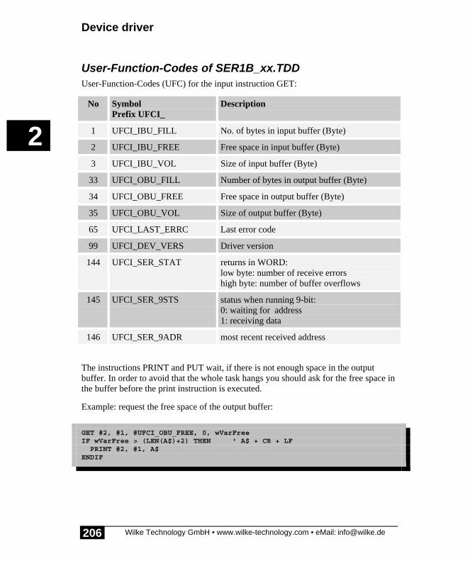
Device driver
Wilke Technology GmbH • www.wilke-technology.com • eMail: [email protected]
2
206
User-Function-Codes of SER1B_xx.TDDUser-Function-Codes (UFC) for the input instruction GET:
No SymbolPrefix UFCI_
Description
1 UFCI_IBU_FILL No. of bytes in input buffer (Byte)
2 UFCI_IBU_FREE Free space in input buffer (Byte)
3 UFCI_IBU_VOL Size of input buffer (Byte)
33 UFCI_OBU_FILL Number of bytes in output buffer (Byte)
34 UFCI_OBU_FREE Free space in output buffer (Byte)
35 UFCI_OBU_VOL Size of output buffer (Byte)
65 UFCI_LAST_ERRC Last error code
99 UFCI_DEV_VERS Driver version
144 UFCI_SER_STAT returns in WORD:low byte: number of receive errorshigh byte: number of buffer overflows
145 UFCI_SER_9STS status when running 9-bit:0: waiting for address1: receiving data
146 UFCI_SER_9ADR most recent received address
The instructions PRINT and PUT wait, if there is not enough space in the outputbuffer. In order to avoid that the whole task hangs you should ask for the free space inthe buffer before the print instruction is executed.
Example: request the free space of the output buffer:
GET #2, #1, #UFCI_OBU_FREE, 0, wVarFreeIF wVarFree > (LEN(A$)+2) THEN ' A$ + CR + LF PRINT #2, #1, A$ENDIF

SER1B - Serial interfaces
Wilke Technology GmbH • www.wilke-technology.com • eMail: [email protected]
2
207
User-Function-Codes for output (instruction PUT):
No SymbolPrefix: UFCO_
Description
1 UFCO_IBU_ERASE Delete input buffer
33 UFCO_OBU_ERASE Delete output buffer
65 UFCO_ERRC_RESET reset most recent OK-/WARNING-/ERROR-Code
94 UFCO_SET_SERIAL set serial parameter
128 UFCO_SET_ISEP set limiter characters for instruction INPUT
129 UFCO_RES_ISEP delete limiter characters for INPUT
130 UFCO_SER_ECHO generate echo chars into the output buffer(YES/NO)
131 UFCO_SER_9BIT 9-bit mode only: set 9th bit to ‘0’ or ‘1’
132 UFCO_SER_9ADR 9-bit mode only: set address of this modulevalue 0…0FFh. Setting 100h clears the address.
133 UFCO_SER_9RTS set RTS to’0’ = not ready’1’ = ready
Example: set new parameter to serial channel 1:
PUT #2,#1, #UFCO_SET_SERIAL, BD_38_400, DP_8E, YES
The standard limiter signs of the instruction INPUT are COMMA and RETURN. Otherlimiter characters can be set using the User Function Code UFCO_SET_ISEP. Beforenew characters are set the existing ones can be deleted from the list. Characters to beadded to the list or deleted from the list are given in code areas.
PUT #D, #C, #UFCO_SET_ISEP, startcode, endcode, startcode, endcode

Device driver
Wilke Technology GmbH • www.wilke-technology.com • eMail: [email protected]
2
208
If you delete the limiter characters without setting new ones the instruction INPUTwill terminate only when the input string or input variable is full.
Example: set new limiter character for the instruction INPUT on the serial channel 0:
PUT #2,#0, #UFCO_RES_ISEP, 0, 255 ‘ delete all limiter charsPUT #2,#0, #UFCO_SET_ISEP, 10, 10 ‘ set LF as limiter char
Example: set all control characters as well as characters above 7Fh as limitercharacters for the instruction INPUT on the serial channel 0:
PUT #2,#0, #UFCO_RES_ISEP, 0, 255 ‘ delete all limiter charsPUT #2,#0, #UFCO_SET_ISEP, 0, 31, 7fh, 0ffh
Example: delete COMMA as limiter character for the instruction INPUT on the serialchannel 0:
PUT #2,#0, #UFCO_RES_ISEP, 2ch, 2ch ‘ delete limiter chars comma‘ orPUT #2,#0, #UFCO_RES_ISEP, ‘,,’
Example:
PUT #2,#0, #UFCO_SET_ISEP, ‘acXZ55’‘ set the following chars as limiter chars:‘ a, b, c, X, Y, Z, 5
Example: generate echo on serial channel 0:
PUT #2,#0, #UFCO_SER_ECHO, YES
�

SER1B - Serial interfaces
Wilke Technology GmbH • www.wilke-technology.com • eMail: [email protected]
2
209
HandshakeThe device driver ‘SER1.TDD’ supports hardware handshaking on serial channel 0.Data can only be transmitted when the CTS line is set to a V.24 positive level, i.e.there is a 'SPACE' on the line. When the serial channel 0 input buffer becomes full,the RTS line is set to ‘MARK’ or a negative RS-232 level.
In order to use your own software handshake protocol on channel 0, CTS should beconnected to constant ‘SPACE’ or with the RTS output.
TTL level RS-232 level Name Comment
high>2V
negative–3V to –15V
MARK busy, not readyidle state on transmit line
low<0.8V
positive+3V to +15V
SPACE readytransmitted TTL-low bits on transmit line
OutputOutput is done with PUT, PRINT or PRINT_USING.
Put outputs characters as bytes they are without conversion into ASCII (numbers) andwithout appending CR and LF. Only one argument is possible.
PRINT or PRINT_USING format numbers before outputting them. Numbers areconverted into ASCII-characters. A sequence of CR+LF is appended. More than oneoutput argument are allowed. Semicolon and comma have special functions.PRINT_USING works like PRINT but formats numbers according a given format(see USING).

Device driver
Wilke Technology GmbH • www.wilke-technology.com • eMail: [email protected]
2
210
Difference between output with PUT and PRINT:
Instruction Output
PUT #SER, 255 1 byte with the value 255
PUT #SER, 12345678h 4 bytes (low 1st): 78h, 56h, 34h, 12h
PRINT #SER, 255 5 bytes: ASCII 2, 5, 5, CR, LF
PRINT #SER, 12345678h 11 bytes (decimal value): “305419896”, CR, LF
Output and controlling the bufferIf output is proceeded even if there is not enough space in the buffer left then theinstruction PUT or PRINT (and with this the whole task) waits. Long or endlesswaiting can be avoided when the buffer level is requested before carry out the PUT otPRINT instruction.
Example: output only if there is enough space in the output buffer:
GET #SER, #0, #UFCI_OBU_FREE, 0, FREE ' request space in buffer IF FREE > 30 THEN ' if at least 30 bytes free PUT #SER, A ' ENDIF
Input charactersThe device driver stores received bytes in the input buffer. There is one input bufferfor each channel. The bytes are read with GET, INPUT or INPUT_LINE.
INPUT and INPUT_LINE read and wait until a separator character is read. Aseparator character breaks an input stream into two inputs. The most commonseparator for inputs is the character RETURN.
GET does not wait, and only reads if something is in the buffer. If a numerical valueshould be read, then the value is read as zero, if
• the buffer is empty• the buffer contained a zero value

SER1B - Serial interfaces
Wilke Technology GmbH • www.wilke-technology.com • eMail: [email protected]
2
211
Both cases are distinguished, if the buffer is requested before reading. For a valid readoperation enough bytes for the variable to be read should be there.
Example: check if at least one byte is in the input buffer:
GET #SER, #0, #UFCI_IBU_FILL, 0, FI ' read input buffer level IF FI > 0 THEN ' if s.th. is in the buffer GET #SER, #0, 1, B ' then read a byte ENDIF
The following example program shows the different ways of output and how to readfrom a buffer. Connect a terminal and step through the program.

Device driver
Wilke Technology GmbH • www.wilke-technology.com • eMail: [email protected]
2
212
Program example:
'--------------------------------------------------------------------'Name: SER1B_1.TIG'send and receives characters and displays them on the LCD'connect terminal at SER0'--------------------------------------------------------------------#INCLUDE DEFINE_A.INC 'general definitions#INCLUDE UFUNC3.INC 'User Function Codes
TASK MAIN BYTE EVER 'for endless loop WORD FREE 'free space in buffer WORD FI 'fill level of buffer LONG A
INSTALL_DEVICE #SER, "SER1B_K1.TDD", & 'install serial driver BD_9_600, DP_8N, YES, & 'setting SER0 BD_9_600, DP_8N, YES 'setting SER1'install LCD-driver (BASIC-Tiger) INSTALL DEVICE #LCD, "LCD1.TDD"'install LCD-driver (TINY-Tiger)'INSTALL DEVICE #LCD, "LCD1.TDD", 0, 0, 0, 0, 0, 0, 80h, 8
PUT #SER, "abcd" 'outputs 4 bytes on channel 0 PRINT #SER, "abcd" 'prints on channel 0 (6 bytes) PRINT #SER, "abcd"; 'prints on channel 0 (4 bytes) PRINT #SER, #0, "abcd" 'prints also on channel 0
A = 44434241h 'A contains ASCII "ABCD" GET #SER, #0, #UFCI_OBU_FREE, 0, FREE 'request free space in buffer IF FREE > 3 THEN 'if at least 4 bytes free PUT #SER, A 'once with PUT ENDIF
PRINT #SER, A 'once with PRINT '44434241h = decimal 1145258561 USING "UH<8><8> 0 0 0 0 8" 'format as HEX, 8 digits PRINT_USING #SER, A
FOR EVER = 0 TO 0 STEP 0 'endless loop GET #SER, #0, #UFCI_IBU_FILL, 0, FI 'read filling of input buffer IF FI > 0 THEN 'if something is in the buffer GET #SER, #0, 1, B 'then read one byte PRINT #LCD, B; 'display it as a number ENDIF NEXTEND

SER1B - Serial interfaces
Wilke Technology GmbH • www.wilke-technology.com • eMail: [email protected]
2
213
RS-485-ModeBoth channels of the serial interface can also be operated as RS-485-interfaces. Acontrol pin is hereby needed to activate the RS-485-transmitter when transmission isto take place and deactivates the transmit module after the last bit has been sent.
Additional parameters during installation of the driver determine the control pins andpolarity of the control:
INSTALL DEVICE #D, "SER1.TDD" [, P1,..., P12]
D is a constant, variable or expression of the data type BYTE,WORD, LONG in the range from 0...63 and stands for thedevice number of the driver.
The existing RTS0 pin can be specified as the control pin for the serial channel 0, thispin can never be used for the serial channel 1, though any other free internal I/O pincan be used.
In the RS-485-mode the driver control pin is activated approx. 25µsec beforetransmission starts and deactivated approx. 25µsec after the last bit has been sent.

Device driver
Wilke Technology GmbH • www.wilke-technology.com • eMail: [email protected]
2
214
A corresponding resistor in the control line should hold the level for 'not enabled' inthe hardware before initialization of the module since otherwise a non-initializedmodule can block the RS-485-Bus.
The handshake pin for channel 0 (CTS) must be fixed to 'ready' in the RS-485-mode,in other words to TTL-low.

SER1B - Serial interfaces
Wilke Technology GmbH • www.wilke-technology.com • eMail: [email protected]
2
215

Device driver
Wilke Technology GmbH • www.wilke-technology.com • eMail: [email protected]
2
216
Program example:
'--------------------------------------------------------------------'Name: SER_485.TIG'--------------------------------------------------------------------#INCLUDE DEFINE_A.INC 'general definitions
TASK MAIN'setup both serial channels to control a RS-485 driver chip'set port 9, pin 5 (RTS) as transmit control for serial 0'set port 8, pin 0 as transmit control for serial 1'set both control pins to 1 => enabled=high INSTALL_DEVICE #2, "SER1B_K4.TDD",& BD_19_200, DP_8N, JA, BD_19_200, DP_8N, JA,00100000b,9,0,00000001b,8,0
PRINT #2, "hello world" 'print on both channels PRINT #2, #1, "again hello world"END

SER1B - Serial interfaces
Wilke Technology GmbH • www.wilke-technology.com • eMail: [email protected]
2
217
RS-485 in 9-Bit modeBASIC-Tiger® supports RS-485-operation in the 9-bit mode. All connectedparticipants in the network receive an address (1 Byte). Addresses are identified onthe bus by a set 9th bit, whereas data receive a non-set 9th bit. This procedurefacilitates the decision as to whether data sent on the bus are for the module or not,and thus takes a load off the CPU. IF the address on the bus corresponds with themodule address the following data is written into the receive buffer of the moduleuntil a new 'invalid' address appears on the bus. Addresses are not saved in the receivebuffer.
Note: in 9-bit mode handshake, error counting, and local echo are not available.
Note: setting an address with the value 100h deletes the previous set address.
User-Function-Codes can be used to inquire the status of the module, i.e. whether thisis waiting for an address (nothing received) or whether data is being received:
GET #2,#0, #UFCI_SER_9STS, 0, STATUS
The following example program only shows how the 9th bit is controlled with User-Function-Codes and how a module address is set. A real application needs at least onetransmitter on the bus and one receiver.

Device driver
Wilke Technology GmbH • www.wilke-technology.com • eMail: [email protected]
2
218
Program example:
'--------------------------------------------------------------------'Name: SER1_9B.TIG'--------------------------------------------------------------------#INCLUDE DEFINE_A.INC#INCLUDE UFUNC3.INC
TASK MAIN'setup both serial channels to control a RS-485 driver chip'set port 9, pin 5 (RTS) as transmit control for serial 0'set port 8, pin 0 as transmit control for serial 1'set both control pins to 1 => enabled=high INSTALL_DEVICE #SER, "SER1B_K4.TDD",& BD_19_200, DP_8N, JA, BD_19_200, DP_8N, JA,00100000b,9,0,00000001b,8,0
PUT #SER, #0, #UFCO_SER_9ADR, 85 'set module address to 85
FOR I = 0 TO 0 STEP 0 'endless loop PUT #SER, #0, #UFCO_SER_9BIT, 0 'reset Bit 9 PUT #SER, #1, #UFCO_SER_9BIT, 0 'also channel 1 PUT #SER, #0, "A" PUT #SER, #1, "B" WAIT_DURATION 500 'wait half a second PUT #SER, #0, #UFCO_SER_9BIT, 1 'set bit 9 PUT #SER, #1, #UFCO_SER_9BIT, 1 'also channel 1 PUT #SER, #0, "A" PUT #SER, #1, "B" WAIT_DURATION 500 'wait half a second NEXTEND
Master and Slave with 9-bit addressesA simple practical example shows how the sender, called 'Master’ sends an addresswith 9th bit set, and subsequently sends data without the 9th bit set. Connect a ‚Slave’running SER1_9B_SLAVE.TIG. As the slave program displays the data using thePRINT instruction in this example the Master sinds only ASCII characters.
When applicating the 9-bit addresses the following must be considered: when givingthe command to set the bit 9 e.g. ‚high’then the command is processed immediately(setting a bit in the UART). This will take effect also on characters which are still inthe output buffer and not yet sent. Before setting (or resetting) the 9th bit you shouldrequest the output buffer level and, if necessary, wait. Sending data of more than one

SER1B - Serial interfaces
Wilke Technology GmbH • www.wilke-technology.com • eMail: [email protected]
2
219
character takes more time than the PUT- or PRINT-instruction need, which just storesthe output data in the buffer. The device driver then sends the data as fast as theinterrupts from the UART allow. When bit 9 is set too early then data will be sentwith 9th bit set.
Program example:
'--------------------------------------------------------------------'Name: SER1_9B_MASTER.TIG'Master sends an address with set 9th bit and subsequent data'Connect a slave containing SER1_9B_SLAVE.TIG'--------------------------------------------------------------------user var strict 'check var declarations#include UFUNC3.INC 'User Function Codes#include DEFINE_A.INC 'general symbol definitions
#define CH9 0 'channel used for 9-bit RS-485#define MASTER 99 'address of master#define SLAVE1 1 'address of slave 1#define SLAVE2 2 'address of slave 2
TASK MAIN BYTE ever
'setup both serial channels to control a RS-485 driver chip'set port 9, pin 5 (RTS) as transmit control for serial 0'set port 8, pin 0 as transmit control for serial 1'set both control pins to 1 => enabled=high install_device #SER, "SER1B_K1.TDD", & BD_19_200, DP_9N, YES, & 'setting SER0 BD_19_200, DP_9N, YES 'setting SER1'install LCD-driver (BASIC-Tiger) INSTALL DEVICE #1, "LCD1.TDD"'install LCD-driver (TINY-Tiger)'INSTALL DEVICE #1, "LCD1.TDD", 0, 0, 0, 0, 0, 0, 80h, 8
put #SER, #CH9, #UFCO_SER_9ADR, MASTER 'set module address
for ever = 0 to 0 step 0 'endless loop put #SER, #CH9, #UFCO_SER_9BIT, 1 'set bit 9 put #SER, #CH9, SLAVE1 'send address SLAVE1 wait_duration 3 'wait until sent
put #SER, #CH9, #UFCO_SER_9BIT, 0 'reset Bit 9 print #SER, #CH9, "hello slave 1" 'send message to SLAVE1 print #LCD, "<1>sent to slave 1"; 'display it on LCD wait_duration 20 'wait until sent ' ---------------------------- put #SER, #CH9, #UFCO_SER_9BIT, 1 'set bit 9 put #SER, #CH9, SLAVE2 'send address SLAVE2 wait_duration 3 'wait until sent

Device driver
Wilke Technology GmbH • www.wilke-technology.com • eMail: [email protected]
2
220
put #SER, #CH9, #UFCO_SER_9BIT, 0 'reset Bit 9 print #SER, #CH9, "hello slave 2" 'send message to SLAVE2 print #LCD, "<1>sent to slave 2"; 'display it on LCD wait_duration 200 'reduce speed of loop nextEND
The module called ‚Slave’ sets its address and receives from ‘Master’ (ASCII-)data.Controlled by the 9-bit addresses the device driver filters the data. Connect a Masterwith SER1_9B_MASTER.TIG.

SER1B - Serial interfaces
Wilke Technology GmbH • www.wilke-technology.com • eMail: [email protected]
2
221
Program example:
'--------------------------------------------------------------------'Name: SER1_9B_SLAVE.TIG'Slave sets its address and receives data (ASCII) from Master.'The device driver filters the data by the use of 9-bit addresses.'Connect a master containing SER1_9B_MASTER.TIG'--------------------------------------------------------------------user var strict 'check var declarations#include UFUNC3.INC 'User Function Codes#include DEFINE_A.INC 'general symbol definitions
#define CH9 0 'channel used for 9-bit RS-485#define MASTER 99 'address of master#define SLAVE1 1 'address of slave 1#define SLAVE2 2 'address of slave 2
TASK MAIN BYTE ever WORD fi 'buffer fill level STRING c$
'setup both serial channels to control a RS-485 driver chip'set port 9, pin 5 (RTS) as transmit control for serial 0'set port 8, pin 0 as transmit control for serial 1'set both control pins to 1 => enabled=high install_device #SER, "SER1B_K1.TDD", & BD_19_200, DP_9N, YES, & 'setting SER0 BD_19_200, DP_9N, YES 'setting SER1'install LCD-driver (BASIC-Tiger) INSTALL DEVICE #1, "LCD1.TDD"'install LCD-driver (TINY-Tiger)'INSTALL DEVICE #1, "LCD1.TDD", 0, 0, 0, 0, 0, 0, 80h, 8
put #SER, #CH9, #UFCO_SER_9ADR, SLAVE2 'set module address
for ever = 0 to 0 step 0 'endless loop get #SER, #CH9, #UFCI_IBU_FILL, 0, fi while fi > 0 'as long as data in buffer get #SER, #CH9, 1, c$ 'read a byte print #LCD, c$; 'dsiplay it on LCD endwhile 'ASCII and CRLF only nextEND

Device driver
Wilke Technology GmbH • www.wilke-technology.com • eMail: [email protected]
2
222
Empty Page

SER2 - Serial interfaces through software
Wilke Technology GmbH • www.wilke-technology.com • eMail: [email protected]
2
223
SER2 - Serial interfaces through softwareThis device driver enables an asynchronous serial input and output on internal I/O-pins. The interface has been implemented purely in the software. When installing thedriver the file name determines at which pins the serial input and output takes place.The baud rate is determined by the TIMERA setting as well as the prescaler of thedevice driver.
The driver can be set to individual requirements:
• RxD + TxD: activate/deactivate individual channels.• RxD + TxD: each with 256 byte FiFo buffer.• RxD + TxD: with flow control: RTS / CTS activate/deactivate.• TxD: RS-485 bus access control TE activate/deactivate.• Data-Bits: Data format: 1...8 Bits.• Parity-Bit: No, Even, Odd, Mark, Space.• Baud rates: quasi-infinitely variable baud rates via TIMERA and Prescaler
in the range from 12 kBd -send (with 1 x TxD) up to 3 Bd.• Level: TRUE + INVERSE level possible for RS-232 with/without power
driver.• PINs: RxD, TxD, RTS, CTS and TE can be laid to almost any I/O-pin of the
Tiger.• Channels: up to 8 serial channels (RxD / TxD in random mixture).
Note: SER2_XX.TDD puts much more strain on the CPU than a driver such asSER1B_xx.TDD since several System-Task calls are carried out for every single bit.The following should therefore be taken into account when using this driver:
• only use SER2 if no free CPU performance is available.• do not select too high a total baud rate for all RxD and TxD channels:• with current modules: sum total = max. approx. 10 kBaud.• e.g.: 5 X TxD at 1200 Bd or: 1 X RxD + TxD at 4800 Bd.• The Debug function can be impaired with a higher CPU work-load.
File name: SER2_pp.TDD
INSTALL DEVICE #D, "SER2_pp.TDD", P1,...P7
Note: TIMERA.TDD must be integrated beforehand.

Device driver
Wilke Technology GmbH • www.wilke-technology.com • eMail: [email protected]
2
224
D is a constant, variable or expression of the data type BYTE,WORD, LONG in the range 0...63 and stands for the devicenumber of the driver.
pp in the file name stands for the position of the send pin(Port,Pin). A table further below in the text shows the locationof the pins arising from the selection of the device driver.
P1...P7 the following table shows the meaning of the parameters P1 toP7:

SER2 - Serial interfaces through software
Wilke Technology GmbH • www.wilke-technology.com • eMail: [email protected]
2
225
leaveunchanged
Description of the parameter
P1 0EEH is a parameter to determine the number of data bits. Value:1...8
P2 0EEH is a parameter to determine the parity:0 = NO1 = SPACE2 = Even3 = Odd4 = MARK
P3 0EEH 0 = TRUE1 = INVERS
P4 - Transmitter Pre-Scaler0 = no Transmitter present1 = without Prescaler2...255 = Prescaler Factor
P5 - Receive Oversample0,1,2 = no Receiver present3...255 = Oversample-Factor
P6 - Reserved, always 1.
P7 0EEH Hardware-Handshake Pins:lower 3 Bits:000 = no Handshake-Pins001 = CTS-Pin (input, controls send activity)010 = RTS-Pin (output, shows whether RxD has space in thebuffer)011 = RTS+CTS100 = Transmitter-Enable f. RS-485 (output, shows whetherdata in TxD buffer)

Device driver
Wilke Technology GmbH • www.wilke-technology.com • eMail: [email protected]
2
226
The device driver uses on to four I/O-pins which can be laid almost at random on theinternal I/O pins of the Tiger module. The following table shows which assignmentsare possible by selecting the suitable driver file:
Driver name TxD (out) RxD (in) CTS (in) orTE (out)
RTS (out)
SER2_33.TDD L33 L34 L35 L70
SER2_34.TDD L34 L35 L70 L71
SER2_35.TDD L35 L70 L71 L72
SER2_40.TDD L40 L42 L33 L34
SER2_42.TDD L42 L33 L34 L35
SER2_60.TDD L60 L61 L62 L63
SER2_61.TDD L61 L62 L63 L64
SER2_62.TDD L62 L63 L64 L65
SER2_63.TDD L63 L64 L65 L66
SER2_64.TDD L64 L65 L66 L67
SER2_65.TDD L65 L66 L67 L40
SER2_66.TDD L66 L67 L40 L42
SER2_67.TDD L67 L40 L42 L33
SER2_70.TDD L70 L71 L72 L73
SER2_71.TDD L71 L72 L73 L60
SER2_72.TDD L72 L73 L60 L61
SER2_73.TDD L73 L60 L61 L62
SER2_80.TDD L80 L81 L82 L83
SER2_81.TDD L81 L82 L83 L84
SER2_82.TDD L82 L83 L84 L85
SER2_83.TDD L83 L84 L85 L86
SER2_84.TDD L84 L85 L86 L87
SER2_85.TDD L85 L86 L87 L70

SER2 - Serial interfaces through software
Wilke Technology GmbH • www.wilke-technology.com • eMail: [email protected]
2
227
Driver name TxD (out) RxD (in) CTS (in) orTE (out)
RTS (out)
SER2_86.TDD L86 L87 L70 L71
SER2_87.TDD L87 L70 L71 L72
Both incoming and sent data will be buffered in a buffer of 256 bytes. Size, level orremaining space of the input and output buffer as well as the driver version can beinquired with the User-Function codes.
User-Function-Codes of the SER2_xx.TDDUser-Function-Codes for inquiries (instruction GET):
No SymbolPrefix UFCI_
Description
1 UFCI_IBU_FILL No. of bytes in input buffer (Byte)
2 UFCI_IBU_FREE Free space in input buffer (Byte)
3 UFCI_IBU_VOL Size of input buffer (Byte)
33 UFCI_OBU_FILL Number of bytes in output buffer (Byte)
34 UFCI_OBU_FREE Free space in output buffer (Byte)
35 UFCI_OBU_VOL Size of output buffer (Byte)
65 UFCI_LAST_ERRC Last error code
99 UFCI_DEV_VERS Driver version
If there is not enough space in the output buffer and you nevertheless wish to outputthe instruction PUT or Print (and thus the complete task) waits until space once againbecomes free in the buffer.
Example: inquire the level of the output buffer to determine whether there is enoughspace for the output:
GET #2, #0, #UFCI_OBU_FILL, 0, wVarFillIF wVarFill > (LEN(A$)+2) THEN ' A$ + CR + LF PRINT #2, #0, A$ENDIF

Device driver
Wilke Technology GmbH • www.wilke-technology.com • eMail: [email protected]
2
228
User-Function-Codes for the instruction PUT following command:
No SymbolPrefix: UFCO_
Description
1 UFCO_IBU_ERASE Delete input buffer
33 UFCO_OBU_ERASE Delete output buffer
94 UFCO_SET_SERIAL set serial parameter
128 UFCO_SET_ISEP set limiter characters for instruction INPUT
129 UFCO_RES_ISEP delete limiter characters for INPUT
Example: set new parameter on serial channel. The parameters will be output in thesame way as in the INSTALL line, but only the first 5 parameters are authorised:
' data,par,inv,TxPre,RxOvs,-,handshakePUT #SER2, 8, 3, 1, 3, 3,1, 0
COMMA and RETURN are regarded as separator characters by default for theinstruction INPUT. The separator characters can be changed using the User-Function-Code UFCO_SET_ISEP. Before setting new characters the already set characters canbe deleted. The characters to be set or deleted are specified as code areas:
PUT #D, #C, UFCO_SET_ISEP, Startcode, Endcode, Startcode, Endcode
If you delete the standard separators without setting new ones an INPUT instructionwill only be terminated when the Input buffer is full.
Example: set new separator LINE-FEED for the instruction input on the serialchannel 0:
PUT #2,#0, #UFCO_RES_ISEP, 0, 255 ‘ delete all separatorsPUT #2,#0, #UFCO_SET_ISEP, 10, 10 ‘ set Line-Feed as separator
�

SER2 - Serial interfaces through software
Wilke Technology GmbH • www.wilke-technology.com • eMail: [email protected]
2
229
Example: set all control characters as well as characters as of 7Fh as separatorcharacters for the instruction input on the serial channel 0:
PUT #2, #0, #UFCO_RES_ISEP, 0, 255 ‘ delete all separators ‘ set new code area as separatorsPUT #2, #0, #UFCO_SET_ISEP, 0, 31, 127, 255
Example: delete comma as separator character for the instruction input on the serialchannel 0:
PUT #2, #0, #UFCO_RES_ISEP, 2ch, 2ch ‘ delete comma as separator‘ oderPUT #2, #0, #UFCO_RES_ISEP, ‘,,’ ‘ delete comma as separator
A further example:
PUT #1, #0, #UFCI_SET_ISEP, 'acXZ55'‘ set as INPUT separators the following characters:‘ a, b, c, X, Y, Z, 5
Example: produce echo on serial channel 0:
PUT #2, #0, #UFCO_SER_ECHO, YES
The example program sends on pin L80 (TxD and receives on pin L81 (RxD).Connect both pins.

Device driver
Wilke Technology GmbH • www.wilke-technology.com • eMail: [email protected]
2
230
Program example:
'--------------------------------------------------------------------'Name: SER2.TIG'sends characters, and diplays received characters'connect pins L80 (TxD) and L81 (RxD)'--------------------------------------------------------------------user_var_strict 'variables must be declared#include DEFINE_A.INC 'general defines#include UFUNC3.INC 'definitions of user function codes
TASK MAIN BYTE I STRING A$
'install LCD-driver (BASIC-Tiger) INSTALL DEVICE #lcd, "LCD1.TDD"'install LCD-driver (TINY-Tiger)'INSTALL DEVICE #1, "LCD1.TDD", 0, 0, 0, 0, 0, 0, 80h, 8 INSTALL_DEVICE #TA, "TIMERA.TDD",2,173 '3612Hz for 1200baud INSTALL_DEVICE #SER2,"SER2_80.TDD", & 8, & 'data bits 0, & 'parity 0=none 0, & 'invert 0=true, 1=invers 3, & 'tx prescaler 3, & 'rx oversample 1, & 'reserved, always 1 0 'handshake, 0=none
PUT #SER2, "hello world<13><10>" 'output with PUT PRINT #SER2, "again hello world" 'output with PRINT FOR I = 0 TO 0 STEP 0 GET #SER2, 1, A$ 'read received characters PRINT #LCD, A$; 'show on LCD NEXTEND
The following example is useful for experiments since individual characters are sentand received characters shown at the press of a key
Program example:
'--------------------------------------------------------------------'Name: SER2A.TIG'reads keyboard of Plug & Play Lab'sends the chars on SER2, and displays chars'received from SER2 on the LCD'connect pins L80 (TxD) and L81 (RxD)

SER2 - Serial interfaces through software
Wilke Technology GmbH • www.wilke-technology.com • eMail: [email protected]
2
231
'--------------------------------------------------------------------user_var_strict 'variables must be declared#include DEFINE_A.INC 'general defines#include UFUNC3.INC 'definitions of user function codes#include KEYB_PP.INC 'for keyboard of Plug & Play Lab
TASK MAIN BYTE ever STRING key$, s$ 'key and serial character
'install LCD-driver (BASIC-Tiger) INSTALL DEVICE #LCD, "LCD1.TDD"'install LCD-driver (TINY-Tiger)'INSTALL DEVICE #LCD, "LCD1.TDD", 0, 0, 0, 0, 0, 0, 80h, 8 install_device #TA, "TIMERA.TDD",2,173 '3612Hz for 1200baud
INSTALL_DEVICE #SER2,"SER2_80.TDD", & 8, & 'data bits 0, & 'parity 0=none 0, & 'invert 0=true, 1=invers 3, & 'tx prescaler 3, & 'rx oversample 1, & 'reserved, always 1 0 'handshake, 0=none
call init_keyb ( LCD ) 'init keyboard driver
for ever = 0 to 0 step 0 'endless loop get #SER2, 1, s$ 'read received characters if s$ <> "" then 'if serial char there print #LCD, asc(s$); 'show on LCD as ASCII code endif get #LCD, 1, key$ 'read keyboard if key$ <> "" then 'if key there put #SER2, key$ 'send on soft serial port endif wait_duration 50 'loop speed nextEND

Device driver
Wilke Technology GmbH • www.wilke-technology.com • eMail: [email protected]
2
232
Empty Page

SER4 - Serial direct in strings with up to 614200baud
Wilke Technology GmbH • www.wilke-technology.com • eMail: [email protected]
2
233
SER4 - Serial direct in strings with up to614200baudThis device driver is largely compatible with SER1_xx.TDD, but enables higher baudrates (up to 614200baud) as well as the serial input and output directly in stringswhich assume the function of the I/O buffer. SER4 thus supports a high datathroughput particularly at higher baud rates.
Further information on SER4_xx.TDD: :
• Control the data flow in the DACC-mode• Data output in the DACC-mode• Data output with Reload in the DACC-mode• Data receipt in the DACC-mode• Data receipt with Reload in the DACC-mode• Special features of the SER4 device driver
File name: SER4_K1.TDD
INSTALL DEVICE #D, "SER4_K1.TDD", P1,...P12
D is a constant, variable or expression of the data type BYTE,WORD, LONG in the range 0...63 and stands for the devicenumber of the driver.
P1...P12 the following table shows the meaning of the parameters P1 toP12: :
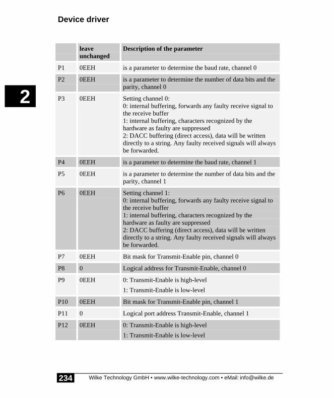
Device driver
Wilke Technology GmbH • www.wilke-technology.com • eMail: [email protected]
2
234
leaveunchanged
Description of the parameter
P1 0EEH is a parameter to determine the baud rate, channel 0
P2 0EEH is a parameter to determine the number of data bits and theparity, channel 0
P3 0EEH Setting channel 0:0: internal buffering, forwards any faulty receive signal tothe receive buffer1: internal buffering, characters recognized by thehardware as faulty are suppressed2: DACC buffering (direct access), data will be writtendirectly to a string. Any faulty received signals will alwaysbe forwarded.
P4 0EEH is a parameter to determine the baud rate, channel 1
P5 0EEH is a parameter to determine the number of data bits and theparity, channel 1
P6 0EEH Setting channel 1:0: internal buffering, forwards any faulty receive signal tothe receive buffer1: internal buffering, characters recognized by thehardware as faulty are suppressed2: DACC buffering (direct access), data will be writtendirectly to a string. Any faulty received signals will alwaysbe forwarded.
P7 0EEH Bit mask for Transmit-Enable pin, channel 0
P8 0 Logical address for Transmit-Enable, channel 0
P9 0EEH 0: Transmit-Enable is high-level
1: Transmit-Enable is low-level
P10 0EEH Bit mask for Transmit-Enable pin, channel 1
P11 0 Logical port address Transmit-Enable, channel 1
P12 0EEH 0: Transmit-Enable is high-level
1: Transmit-Enable is low-level

SER4 - Serial direct in strings with up to 614200baud
Wilke Technology GmbH • www.wilke-technology.com • eMail: [email protected]
2
235
Baud is a parameter to determine the baud rate. The followingsymbolic identifiers are specified in DEFINE_A.INC:
Data_Par is a parameter to determine the number of data bits and theparity . The following symbolic identifiers are specified inDEFINE_A.INC:
Number data bits, parity:
Rec.flag = NO, characters will be suppressed which are recognized bythe hardware as faulty .= YES, forwards any faulty receive characters to the receivebuffer.
‘etc.’ stands for the data of the second serial channel. The datarepeats itself in the same form as for the first channel.
In the buffered mode, data which is to be sent is initially written in the output bufferof the device driver. Received date also initially enters the receive buffer of the driver.The buffers can be accessed via the instructions PUT, PRINT, PRINT_USING, GET,INPUT and INPUT_LINE.
In the DACC mode (DACC = Direct ACCess) the data to be sent is saved directly in aTiger-BASIC® string. Since strings can be accessed immediately this increases theefficiency saves CPU-time. The advantages of the DACC mode are felt particularly athigh baud rates and high data throughputs.
The DACC mode supports block transfers via a serial channel. The block size can bedynamically controlled during the communication process.
The DACC string must always exist! Thus, variables with only a temporary life, suchas local strings (in subroutines) or temporary strings (expressions), are not allowed.Correct: global or task-local strings.
In the DACC mode the instruction PUT is used to both send and receive data. Theinstructions PRINT, PRINT_USING, INPUT and INPUT_LINE cannot be used in theDACC mode.The instruction GET serves only for status inquiries, not to read data.
In the DACC mode references to static variables are transferred, no data are moved.To enable a smooth data stream, Reload-strings are transferred to the driver during
�
�

Device driver
Wilke Technology GmbH • www.wilke-technology.com • eMail: [email protected]
2
236
both send and receive so that these can change the string as soon as the first string isfull or
The data traffic in SER4 is settled via the following secondary address:
Sec.-Adr.
Symbol (defined inUFUNCn.INC)
Description
Channel 0
0 - Buffered I/O, channel 0
10H DACC0_TX Transfer reference to Send string
12H DACC0_TRLD Transfer reference to Send-Reload string
14H DACC0_RX Transfer reference to Receive string
16H DACC0_RRLD Transfer reference to Receive-Reload string
Channel 1
1 - Buffered I/O, channel 1
11H DACC1_TX Transfer reference to Send string
13H DACC1_TRLD Transfer Send-Reload string
15H DACC1_RX Transfer reference to Receive string
17H DACC1_RRLD Transfer reference to Receive-Reload string
If a serial channel is installed in the DACC mode it can only be accessed in this mode.If, for example, channel 0 has been installed in the DACC mode the secondaryaddress 0 is not available for data traffic. However, status information will inquiredvia the secondary address 0. At the same time channel 1 is automatically 'buffered' inthis mode in this case since only one a channel at a time can be in the DACC mode .
Check the data flow in the DACC modeIn the DACC mode the device driver accesses data in the string whilst at the sametime the string can also be accessed by BASIC program which continue to run. ABASIC program thus has to be prevented from accessing a string whilst a send orreceive event is using the string.
During sending the string length and the contents of the string are never changed bythe device driver.

SER4 - Serial direct in strings with up to 614200baud
Wilke Technology GmbH • www.wilke-technology.com • eMail: [email protected]
2
237
During receive the string is modified in different ways: data will be written at thespecified points in the string. The string length can also change or remain the samedepending on the setting.
The data flow can be observed and controlled by reading the status of the devicedriver. Information on the status of the send, receive and reload string is obtained byreading the status at different secondary addresses.
User-Function-Codes for inquiries (instruction GET):
No. Symbol PrefixUFCI_
Sec.-Adr.
Description
147 UFCI_SER_STAT Status
0 4 bytes provide information on the send stringlow WORD: number of unsent bytes in thesend stringhigh WORD: Send-Reload string length
1 4 Bytes provide information on the receivestringlow WORD: number of received bytes in thereceive stringhigh WORD: Receive-Reload string length
2 8 Bytes provide information on the send andreceive stringlowest WORD(1): number of unsent bytes inthe send stringWORD(1): Send-Reload string lengthWORD(2): number of received bytes in thereceive stringhigh WORD(3): Receive-Reload string length
The following lines show how the 8-byte long status is split:
GET #7, #2, #UFCI_SER4_STAT, 8, stat$ ' read DACC status (8 Byte)PRINT #1, " TxD=";NFROMS (stat$,0,2)' Transmit-Buffer statusPRINT #1, "Rel-TxD=";NFROMS (stat$,2,2)' Transmit-RELOAD buffer statusPRINT #1, " RxD=";NFROMS (stat$,4,2)' Receive-Buffer statusPRINT #1, "Rel-RxD=";NFROMS (stat$,6,2)' Receive-RELOAD-Buffer status

Device driver
Wilke Technology GmbH • www.wilke-technology.com • eMail: [email protected]
2
238
User-Function-Codes for the instruction PUT following command:
No Symbol Description
1 UFCO_IBU_ERASE D input buffer
33 UFCO_OBU_ERASE Delete output buffer
135 UFCI_SER_GROF Growth-Flag:2: String size does not change.3: String size set at the start of receipt by theparameters 'Offset' and 'Length'. String neverbecomes shorter.4: String size set to exactly the required lengthat the start of receipt by the parameters 'Offset'and 'Length'. String becomes longer or shorter.
Data output in the DACC modeFor data output in the DACC mode, the data are saved in a string and the devicedriver sent a reference to this string with PUT. Unless otherwise specified thecomplete string will be output.
As soon as the string is transferred to the driver the serial send process starts and canalso be interrupted by this if Handshake lines exist.
1) PUT #7, #10H, X$ ' pass X$ to be output in full length
2) PUT #7, #10H, X$, 17 ' pass X$ for output, starting at pos 17 to the end
3) PUT #7, #10H, X$, 8, 32 ' pass X$ to output 32 bytes beginning at pos 8
The following example program outputs data in the DACC mode, i.e. instead ofprinting to a buffer a string of 5kBytes will be sent to the device driver. The Numberof bytes still to be output will be shown. Since the Handshake is taken into account,CTS must signal ready for operation so that the output can start. Connect for examplea terminal to SER0.

SER4 - Serial direct in strings with up to 614200baud
Wilke Technology GmbH • www.wilke-technology.com • eMail: [email protected]
2
239
Program example:
'--------------------------------------------------------------------'Name: SER4_TX.TIG'send serial data in DACC mode'--------------------------------------------------------------------user_var_strict 'variables must be declared#include DEFINE_A.INC 'general defines#include UFUNC3.INC 'definitions of user function codes
STRING tx$(5k) 'global string
TASK Main BYTE ever 'for endless loop WORD fo 'no. of bytes still to be sent'install LCD-driver (BASIC-Tiger) install_device #LCD, "LCD1.TDD"'install LCD-driver (TINY-Tiger)'INSTALL DEVICE #LCD, "LCD1.TDD", 0, 0, 0, 0, 0, 0, 80h, 8 install_device #SER, "SER4_K1.TDD", & BD_19_200, DP_8N, DACC, & 'setting channel 0 BD_19_200, DP_8N, YES 'setting channel 1
tx$ = "this has been sent using SER4 DACC mode<13><10>" put #SER, #DACC0_TX, tx$ 'send short string
tx$ = fill$ ( "x", 5k ) 'build a long string put #SER, #DACC0_TX, tx$ 'send long string
for ever = 0 to 0 step 0 'endless loop 'show no. of bytes to be sent get #SER, #0, #UFCI_SER4_STAT, 4, fo 'chars to be send fo = fo bitand 0FFFFh print #LCD, "<1Bh>A<0><0><0F0h>to be sent:";fo;" "; nextEND
Data output with Reload in the DACC modeData blocks can be output without interruption if a Reload string is sent to the driveralong with the currently active send string. As soon as the active string has been fullyoutput the Reload-string is taken over at this point and the output continued. After theReload string has been taken over a new Reload string can be transferred. A statusinquiry determines when this time has been reached.
1) PUT #7, #12H, A$ ' pass A$ as a reload value: full length

Device driver
Wilke Technology GmbH • www.wilke-technology.com • eMail: [email protected]
2
240
2) PUT #7, #12H, A$, 17 ' same as above, starting at pos 17 to the end
3) PUT #7, #12H, A$, 8, 32 ' same as above, 32 bytes starting at pos 8

SER4 - Serial direct in strings with up to 614200baud
Wilke Technology GmbH • www.wilke-technology.com • eMail: [email protected]
2
241
Program example:
'--------------------------------------------------------------------'Name: SER4_TX_RELOAD.TIG'send serial data in DACC mode'uses reload buffer to get a continuous output'--------------------------------------------------------------------user_var_strict 'variables must be declared#include DEFINE_A.INC 'general defines#include UFUNC3.INC 'definitions of user function codes
ARRAY tx$(2) OF STRINGS(1k) 'global strings
TASK Main BYTE ever 'for endless loop BYTE j 'array index LONG fo 'no. of bytes still to be sent LONG rest, rld 'in the reload buffer'install LCD-driver (BASIC-Tiger) install_device #LCD, "LCD1.TDD"'install LCD-driver (TINY-Tiger)'INSTALL DEVICE #LCD, "LCD1.TDD", 0, 0, 0, 0, 0, 0, 80h, 8 install_device #SER, "SER4_K1.TDD", & BD_19_200, DP_8N, DACC, & 'setting channel 0 BD_19_200, DP_8N, YES 'setting channel 1
tx$(0) = fill$ ( "a", 1k ) '1kbyte of 'a' tx$(1) = fill$ ( "b", 1k ) '1kbyte of 'b' put #SER, #DACC0_TX, tx$(0) 'begin to send
j = 0 for ever = 0 to 0 step 0 'endless loop 'show no. of bytes to be sent get #SER, #0, #UFCI_SER4_STAT, 4, fo rest = fo bitand 0FFFFh print #LCD, "<1Bh>A<0><0><0F0h>to be sent:";rest;" "; rld = fo shr 16 'and how much is in reload buffer print #LCD, "<1Bh>A<0><1><0F0h> in reload:";rld;" "; if rld = 0 then 'if reload is empty put #SER, #DACC0_TRLD, tx$(j) 'then re-load endif if j = 0 then j = 1 else j = 0 endif nextEND

Device driver
Wilke Technology GmbH • www.wilke-technology.com • eMail: [email protected]
2
242
Data receipt in the DACC modeFor data receipt in the DACC mode a reference to a string is sent to the device driverwith PUT. The received data is saved in the string. During receipt the string can beaccessed from BASIC. Unless otherwise specified the string will be filled fromaddress 0 up to the maximum string length.
1) PUT #7, #14H, X$ ' pass X$ to input data until string is full
2) PUT #7, #14H, X$, 17 ' pass X$ to input start at pos 17, until string full
3) PUT #7, #14H, X$, 8, 32 ' pass X$ to input 32 Bytes, start at pos 8
The following example program shows the number of received characters, the lengthof the receive string (in this example constant) as well as the receive string itself. It isassumed that only printable ASCII characters are received. The receive process can befollowed on the Plug & Play Lab. For this purpose connect a terminal to SER0 andenter characters via the terminal keyboard. The number of received characters growsfrom 0 to 10 and string forward spaced with "xxxxxxxxxx" contains the receivedcharacters.

SER4 - Serial direct in strings with up to 614200baud
Wilke Technology GmbH • www.wilke-technology.com • eMail: [email protected]
2
243
Program example:
'--------------------------------------------------------------------'Name: SER4_TX.TIG'receives serial data in DACC mode (without reload)'--------------------------------------------------------------------user_var_strict 'variables must be declared#include DEFINE_A.INC 'general defines#include UFUNC3.INC 'definitions of user function codes
STRING rx$(10) 'global string
TASK Main BYTE ever 'for endless loop WORD ibu_fill 'input buffer fill level'install LCD-driver (BASIC-Tiger) install_device #LCD, "LCD1.TDD"'install LCD-driver (TINY-Tiger)'install_device #LCD, "LCD1.TDD", 0, 0, 0, 0, 0, 0, 80h, 8 install_device #SER, "SER4_K1.TDD", & BD_19_200, DP_8N, DACC, & 'setting channel 0 BD_19_200, DP_8N, YES 'setting channel 1
rx$ = fill$ ( "x", 10 )'constant receive string length
put #SER, #DACC0_RX, rx$ 'pass receive string
for ever = 0 to 0 step 0 'endless loop 'show no. of bytes received get #SER, #1, #UFCI_SER4_STAT, 4, ibu_fill 'chars received ibu_fill = len(rx$) - (ibu_fill bitand 0FFFFh) print #LCD, "<1Bh>A<0><0><0F0h>received:";ibu_fill;" "; print #LCD, "<1Bh>A<0><1><0F0h>len(rx$):";len(rx$);" "; print #LCD, "<1Bh>A<0><2><0F0h> rx$:";rx$;" "; nextEND

Device driver
Wilke Technology GmbH • www.wilke-technology.com • eMail: [email protected]
2
244
Data receipt with Reload in the DACC modeData block's can be received without interruption if are Reload string is sent to Thedriver along with The currently active receive string. As soon as the active string hasbeen fully received the Reload-string is taken over at this point and the receiptcontinued. After the Reload string has been taken over a new Reload string can betransferred. A status inquiry determines when this time has been reached.
1) PUT #7, #16H, A$ ' pass A$ as a reload value: full length
2) PUT #7, #16H, A$, 17 ' same as above, starting at pos 17 to the end
3) PUT #7, #16H, A$, 8, 32 ' same as above, 32 bytes starting at pos 8
The following example program shows the number of received characters, how manycharacters are in the Reload buffer as well as the contents of both string, here in theform of 2 Array-elements. The received date will always be appended to the string'collect$' every the Reload buffer receives new data to release the string for the nextReload-event. The Length as well as the contents of the receive string can be viewedusing the command 'Monitored Print-outs’ in the menu 'View'. It is assumed that onlyprintable ASCII characters are received. The receive process and the transfer of theReload string can be followed on the Plug & Play Lab. For this purpose connect aterminal to SER0 and enter characters via the terminal keyboard. The number ofreceived characters grows from 0 to 10 and the forward spaced string with"xxxxxxxxxx" contains the received characters. When the buffer is full the receiptwill be continued in the Reload buffer. The Length 10 is temporarily shown in thedisplay of the Reload buffer length.

SER4 - Serial direct in strings with up to 614200baud
Wilke Technology GmbH • www.wilke-technology.com • eMail: [email protected]
2
245
Program example:
'--------------------------------------------------------------------'Name: SER4_RX_RELOAD.TIG'receives serial data on channel SER0 in DACC mode'uses reload buffer and collects data in collect$ (here: max 1k)'--------------------------------------------------------------------user_var_strict 'variables must be declared#include DEFINE_A.INC 'general defines#include UFUNC3.INC 'definitions of user function codes
ARRAY rx$(2) OF STRINGS(10) 'array with 2 strings a 10 bytesSTRING collect$(1k) 'collects received data
TASK Main BYTE ever 'for endless loop BYTE j 'array index BYTE r LONG fi 'no. of bytes received LONG rfill, rld 'in the reload buffer STRING c$(2)'install LCD-driver (BASIC-Tiger) install_device #LCD, "LCD1.TDD"'install LCD-driver (TINY-Tiger)'INSTALL DEVICE #LCD, "LCD1.TDD", 0, 0, 0, 0, 0, 0, 80h, 8 install_device #SER, "SER4_K1.TDD", & BD_19_200, DP_8N, DACC, & 'setting channel 0 BD_19_200, DP_8N, YES 'setting channel 1
rx$(0) = fill$ ( "0", 10 ) '10 bytes of '0' rx$(1) = fill$ ( "1", 10 ) '10 bytes of '1' put #SER, #DACC0_RX, rx$(0) 'pass receive string put #SER, #DACC0_RRLD, rx$(1) 'pass receive reload string
j = 0 collect$ = "" 'begin with empty collect$ for ever = 0 to 0 step 0 'endless loop 'show no. of bytes received get #SER, #1, #UFCI_SER4_STAT, 4, fi rfill = len(rx$(0)) - (fi bitand 0FFFFh) print #LCD, "<1Bh>A<0><0><0F0h>received:";rfill;" "; rld = len(rx$(0)) - (fi shr 16) print #LCD, "<1Bh>A<0><1><0F0h> reload:";rld;" "; print #LCD, "<1Bh>A<0><2><0F0h> rx$(0):";rx$(0);" "; print #LCD, "<1Bh>A<0><3><0F0h> rx$(1):";rx$(1);" "; if rld > 0 then wait_duration 300 'just to see the reload value collect$ = collect$ + rx$(j)'collect received data c$ = chr$ ( j+30h ) '0 or 1 rx$(j) = fill$ ( c$, 10 ) 'prepare string for display put #SER, #DACC0_RRLD, rx$(j)'pass receive reload string if j = 0 then 'toggle array index j = 1

Device driver
Wilke Technology GmbH • www.wilke-technology.com • eMail: [email protected]
2
246
else j = 0 endif endif nextEND
Special features of the SER4 device driver
The following restrictions must be observed depending on the operating mode of thedevice driver SER4:
No. Keyword Comment
1 Receive error • characters always taken over in DACC mode,suppression not planned.
2 Internally bufferedmode
• Baud rates up to 153600 baud are available• all setting parameters are possible
3 Operation withstrings(DACC)
• only possible on one channel at one time, theother channel is available in the buffered modeduring this.
• All baud rates available• Only 8 data bits (not 7 or 9)• Control functions adapted to DACC mode are
available
4 High baud rates • Modules without built-in drive chips• External driver chips must be suitable for the
baud rate

CAN
Wilke Technology GmbH • www.wilke-technology.com • eMail: [email protected]
2
247
CANThe device driver ‘CAN1_xx.TDD’ supports the internal CAN interface of theBASIC-Tiger®-CAN module.
This section contains:
• Description of the device driver CAN1_xx.TDD• CAN messages in the I/O-buffer of the driver• CAN User-Function codes• Bus timing and transfer rate• Error register• Receive filter with Code and Mask• Sending CAN messages• Receiving CAN messages• I/O buffer• Automatic bit rate detection• CAN-bus hardware connection example• A short introduction to CAN• Special features of the BASIC-Tiger®-CAN module• References to CAN• CAN-SLIO Board
Description of the device driver CAN1_xx.TDDThis device driver enables input and output on the CAN-bus in connection with theBASIC-Tiger®-CAN module. The parameters of the CAN interface can be specifiedduring installation of the driver. Some parameters can also be changed during therunning time by commands to the driver.
File names: CAN1_K8.TDD (with 8K buffers)CAN1_K1.TDD (with 1K buffers)CAN1_R1.TDD (with 256 byte buffers)
INSTALL DEVICE #D, "CAN1_xx.TDD", “Code, Mask, Bt0, Bt1, Mod, Oc”
D is a constant, variable or expression of the data type BYTE,WORD, LONG in the range 0...63 and stands for the devicenumber of the driver.
Code is a parameter to determine the Access-Code. 'Code' is always4 bytes long. The range of values for the Access code with
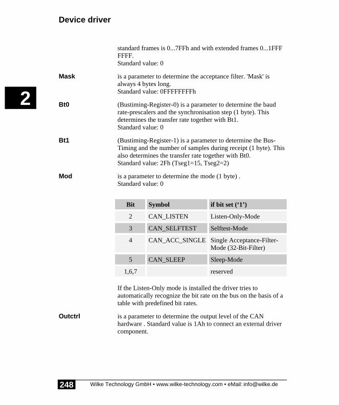
Device driver
Wilke Technology GmbH • www.wilke-technology.com • eMail: [email protected]
2
248
standard frames is 0...7FFh and with extended frames 0...1FFFFFFF.Standard value: 0
Mask is a parameter to determine the acceptance filter. 'Mask' isalways 4 bytes long.Standard value: 0FFFFFFFFh
Bt0 (Bustiming-Register-0) is a parameter to determine the baudrate-prescalers and the synchronisation step (1 byte). Thisdetermines the transfer rate together with Bt1.Standard value: 0
Bt1 (Bustiming-Register-1) is a parameter to determine the Bus-Timing and the number of samples during receipt (1 byte). Thisalso determines the transfer rate together with Bt0.Standard value: 2Fh (Tseg1=15, Tseg2=2)
Mod is a parameter to determine the mode (1 byte) .Standard value: 0
Bit Symbol if bit set (‘1’)
2 CAN_LISTEN Listen-Only-Mode
3 CAN_SELFTEST Selftest-Mode
4 CAN_ACC_SINGLE Single Acceptance-Filter-Mode (32-Bit-Filter)
5 CAN_SLEEP Sleep-Mode
1,6,7 reserved
If the Listen-Only mode is installed the driver tries toautomatically recognize the bit rate on the bus on the basis of atable with predefined bit rates.
Outctrl is a parameter to determine the output level of the CANhardware . Standard value is 1Ah to connect an external drivercomponent.

CAN
Wilke Technology GmbH • www.wilke-technology.com • eMail: [email protected]
2
249
Example for an installation for 500 kBit:
install_device #CAN, "CAN1_K1.TDD", & 0,0,0,0, & ' access code 0ffh,0ffh,0ffh,0ffh, & ' access mask 0,2Fh, & ' bustim1, bustim2 0,1Ah ' mode, outctrl

Device driver
Wilke Technology GmbH • www.wilke-technology.com • eMail: [email protected]
2
250
CAN messages in the I/O-buffer of the driverThe I/O buffers of the Tiger-BASIC®-CAN device driver always contains completeCAN messages and no further bytes. A CAN message starts with the Frame-Info-byte,which determines whether this is a message with an 11 or 29-Bit-Identifier and howmany data bytes are contained therein. The Frame-Info-Byte also contains the RTR-bit. This is followed by 3 Identifier-bytes (standard frame) or 5 Identifier-bytes(extended frame) and then the data bytes depending on the frame type. A CANmessage can transfer 0...8 bytes as useful data.
The Frame-Info-Byte also contains information on
• the frame type (11 or 29 ID-Bits)• the number of data bytes (0...8)• whether this is a Remote-Transmit-Request
The Identifier can
• be 29 bits long and the occupies 4 bytes in the buffer• be 11 bits long and then occupies 2 bytes in the buffer
A standard frame occupies a maximum of 11 bytes, an extended frame a maximum of13 bytes in the buffer. If the device driver does not have at least 13 bytes free in thebuffer free during receipt the message will be rejected and an error registered 'Bufferoverflow'. Between 341 messages (only standard frames without data) and78 message (only extended frames, all with 8 data bytes) fit in a 1kByte bufferdepending on the length of the individually received CAN message.

CAN
Wilke Technology GmbH • www.wilke-technology.com • eMail: [email protected]
2
251
Standard frameThe illustration shows the structure of the standard frame with enlarged Frame-Info-Byte (top) and the ID-byte (enlarged bottom). The length of the message is setautomatically by the device driver. The 11 ID-bits must first be flush left with thehighest-order bit in the two bytes, as shown in the illustration.
0 R T R 0 0 DLC3 DLC2 DLC1 DLC0
info ID1 ID2 data0 data1 data2 data3 data4 data5 data6 data7
ID10 ID9 ID8 ID7 ID6 ID5 ID4 ID3 ID2 ID1 ID0 0 0 0 0 0
4 Bi ts geben Anzahl derDatenbytes in der Message
an. Maximal 8
Frame-Format : 0
Remote Transmi t Request
Structure of the 'Standard Frame'
Standard Frame, Info-bits:
FF Frame-Format bit, here FF=0.0: Standard Frame 1: extended Frame
RTR Remote Transmit Request, send request. Messages with a setRTR-bit will be processed directly by the driver and do notappear in the buffer.
DLC 4 bits specify the number of data bytes in the message (0...8).This bit sets the device driver.

Device driver
Wilke Technology GmbH • www.wilke-technology.com • eMail: [email protected]
2
252
The 11-Bit-Identifier of the CAN message can be found in both ID-bytes, offset by 5bits to the left. The format here is 'high-byte first’, unlike the WORD variables inTiger-BASIC® which are 'low-byte first'.
The ID-bytes are followed by as many data bytes as specified by DLC.
Example for the generation of standard frames in Tiger-BASIC®:
t_id = 7FFh shl 5 ' Transmit-ID, leftbound in WORD' Standardframe mit Frame-Info-Byte, 2 empty ID-Bytes, Datamsg$ = "<0><0><0>" + data$msg$ = ntos$ ( msg$, 1, -2, t_id ) ' insert ID with high-Byte first ' length will be set by device driverprint #CAN, msg$; ' PRINT, with semicolon!!' orput #CAN, msg$

CAN
Wilke Technology GmbH • www.wilke-technology.com • eMail: [email protected]
2
253
Extended Frame
1 R T R 0 0 DLC3 DLC2 DLC1 DLC0
info ID1 ID2 data0 data1 data2 data3 data4 data5 data6 data7
ID10
ID9 ID8 ID7 ID6 ID5 ID4 ID3 ID2 ID1 ID0 0 0 0
4 Bits geben Anzahl derDatenbytes in der Message
an. Maximal 8
Frame-Format: 1
Remote Transmit Request
ID3 ID4
ID11
ID12
ID13
ID14
ID15
ID23
ID22
ID21
ID20
ID19
ID18
ID17
ID16
ID24
ID25
ID26
ID27
ID28
Structure of the 'extended Frame'
Extended Frame, Info-Bits:
FF Frame-Format-Bit, here FF=1.0: Standard Frame1: extended Frame
RTR Remote Transmit Request, send request. Messages with a setRTR-bit will be processed directly by the driver and do notappear in the buffer.
DLC 4 bits specify the number of data bytes in the message (0...8).
The 29-Bit-Identifier of the CAN message can be found in the 4 ID-bytes, offset by 3bits to the left. The format here is 'high-byte first’, unlike the LONG-variables whichare 'low-byte first'.
The ID-bytes are followed by as many data bytes as specified by DLC.

Device driver
Wilke Technology GmbH • www.wilke-technology.com • eMail: [email protected]
2
254
Example for the generation of extended frames in Tiger-BASIC®:
t_id = 1FFFFFFFh shl 3 ' Transmit-ID, linksbuendig in LONG' extended Frame mit Frame-Info-Byte, 4 leeren ID-Bytes, Datenmsg$ = "<80h><0><0><0><0>" + data$msg$ = ntos$ ( msg$, 1, -4, t_id ) ' ID einbauen mit high-Byte zuerst ' Laenge wird vom Treiber eingesetztprint #CAN, msg$; ' PRINT mit Semikolon!!' oderput #CAN, msg$

CAN
Wilke Technology GmbH • www.wilke-technology.com • eMail: [email protected]
2
255
CAN User-Function-CodesUser-Function-Codes for inquiries (Instruction GET):
No SymbolPrefix UFCI_
Description
1 UFCI_IBU_FILL No. of bytes in input buffer (Byte)
2 UFCI_IBU_FREE Free space in input buffer (Byte)
3 UFCI_IBU_VOL Size of input buffer (Byte)
33 UFCI_OBU_FILL Number of bytes in output buffer (Byte)
34 UFCI_OBU_FREE Free space in output buffer (Byte)
35 UFCI_OBU_VOL Size of output buffer (Byte)
65 UFCI_LAST_ERRC Last error code
152 UFCI_CAN_MODE reads CAN register MODE
153 UFCI_CAN_STAT reads CAN register STAT
154 UFCI_CAN_ALC reads copy from ‘arbitration lost register’
155 UFCI_CAN_ECC reads copy from ‘error code capture register’
156 UFCI_CAN_EWL reads copy from ‘error warning limit register’
157 UFCI_CAN_RXERR reads copy from ‘rx error counter register’
158 UFCI_CAN_TXERR reads copy from ‘tx error counter register’
159 UFCI_CAN_RMC reads copy from ‘rx message counter’
99 UFCI_DEV_VERS Driver version

Device driver
Wilke Technology GmbH • www.wilke-technology.com • eMail: [email protected]
2
256
User-Function-Codes for output (Instruction PUT):
No SymbolPrefix: UFCO_
Description
1 UFCO_IBU_ERASE Delete input buffer
33 UFCO_OBU_ERASE Delete output buffer
65 UFCO_ERRC_RESET reset most recent OK-/WARNING-/ERROR-Code
136 UFCO_CAN_CODE sets CAN register CODE
137 UFCO_CAN_MASK sets CAN register MASK
138 UFCO_CAN_MODE sets CAN register MODE
139 UFCO_CAN_BUSTIM0 sets CAN register BUSTIM0
140 UFCO_CAN_BUSTIM1 sets CAN register BUSTIM1
141 UFCO_CAN_OUTCTRL sets CAN register OUTCTRL
176 UFCO_CAN_RESET CAN soft reset
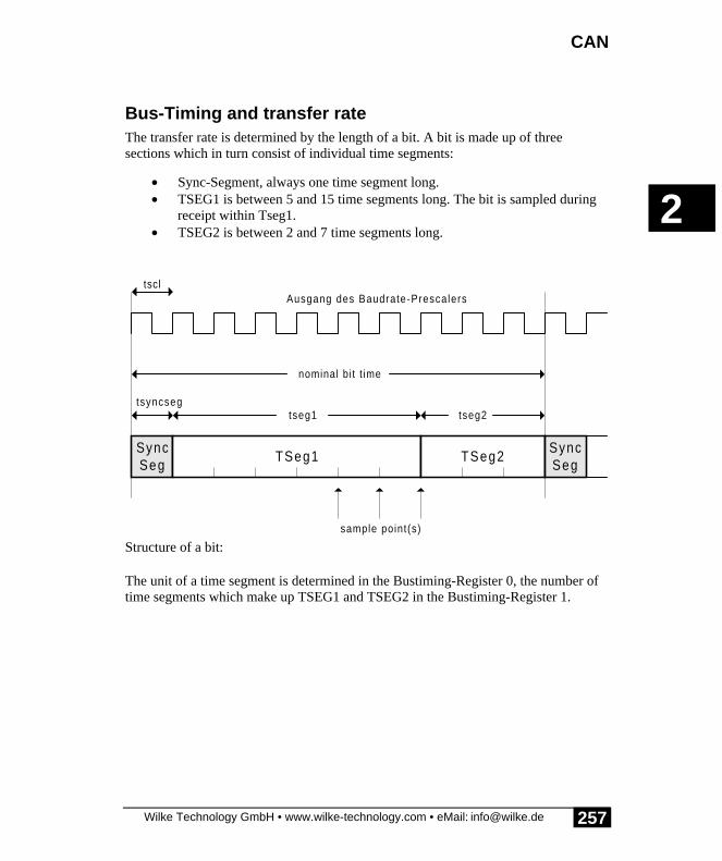
CAN
Wilke Technology GmbH • www.wilke-technology.com • eMail: [email protected]
2
257
Bus-Timing and transfer rateThe transfer rate is determined by the length of a bit. A bit is made up of threesections which in turn consist of individual time segments:
• Sync-Segment, always one time segment long.• TSEG1 is between 5 and 15 time segments long. The bit is sampled during
receipt within Tseg1.• TSEG2 is between 2 and 7 time segments long.
SyncSeg
TSeg1 TSeg2SyncSeg
nominal bi t t ime
tseg1 tseg2
tscl
sample point(s)
Ausgang des Baudrate-Prescalers
tsyncseg
Structure of a bit:
The unit of a time segment is determined in the Bustiming-Register 0, the number oftime segments which make up TSEG1 and TSEG2 in the Bustiming-Register 1.

Device driver
Wilke Technology GmbH • www.wilke-technology.com • eMail: [email protected]
2
258
Bustiming-Register 0The length of a time segment 'tscl' is determined in the Bustiming-Register 0, bythe baud rate-prescaler BRP. The 6-bit prescaler can assume values between 0 and31.
1 Time segment: tscl = 0,1 * (BRP+1) µsec
1 Bit time = Tsync + Tseg1 + Tseg2
The upper bits in this register determine the synchronisation step. The value SJWdetermines the maximum number of clock cycles by which a bit may be shortened orextended to compensate phase differences between different bus controllers throughresynchronisation.
Bustiming-Register 0
Bit7 Bit6 Bit5 Bit4 Bit3 Bit2 Bit1 Bit0
SJW1 SJW0 BRP5 BRP4 BRP3 BRP2 BRP1 BRP0
Bustiming-Register 1Bustiming-Register-1 determines the number of time segments in Tseg1 andTseg2 and how often the received bit is sampled (once or three times).
Bustiming-Register 1
Bit7 Bit6 Bit5 Bit4 Bit3 Bit2 Bit1 Bit0
SAM TSEG2.2 TSEG2.1 TSEG2.0 TSEG1.3 TSEG1.2 TSEG1.1 TSEG1.0
SAM=1: The bus is sampled three times. Recommend for slow andmedium-speed buses if filtration of spikes on the bus bringsadvantages.
SAM=0: The bus is sampled once. Recommend for fast buses.
Which values of Tseg1 and Tseg2 guarantee a safe receipt depends on the physicalcharacteristics of the transmission medium, including driver components, optical

CAN
Wilke Technology GmbH • www.wilke-technology.com • eMail: [email protected]
2
259
coupling device. These characteristics finally determine the achievable baud rate andline length.
Some common settings can be found in the following table (achievable bus lengthsare only references):
Bit rate Bustim0 Bustim1 Bt1Tseg1
Bt1Tseg2
Buslength
1 Mbit 0 43h 3 4 25m
500 kBit 0 5Ch 12 5 100m
250 kBit 1 5Ch 12 5 250m
125 kBit 3 5Ch 12 5 500m
100 kBit 4 5Ch 12 5 650m
The bit rate can be specified during installation of the driver by parameters.
During the running time the Bustiming settings can be changed using User-Function-Codes.Note: the output buffer should be empty whilst setting Bustim0 or Bustim1 since theinternal CAN chip is temporarily in the rest mode. It is also temporarily not ready toreceive.
Example: set 100kBit acc. to above table during the running time:
PUT #CAN, #0, #UFCO_CAN_BUSTIM0, 4PUT #CAN, #0, #UFCO_CAN_BUSTIM1, 5CH

Device driver
Wilke Technology GmbH • www.wilke-technology.com • eMail: [email protected]
2
260
Error RegisterBoth the correct receipt of a CAN message and faulty statuses on the CAN bus triggera Receiver-Interrupt. During the Interrupt-processing the device driver determineswhether a fault-free package has been received or whether errors have occurred. Inany case the values associated with error statuses will be refreshed and be given aUser-Function code for the next error inquiry. If further errors occur before the errorinquiry the later error code will be saved in each case.
The following error inquiries are possible:
User-Function-Code Bit(s) Meaning
UFCI_CAN_STAT 0 Receive Buffer Status: 0: empty 1: full
1 Receive Overrun: 0: no 1: yes
Data-Overrun. Occurs if a new CAN-Message isreceived although there is not enough space in thereceive area of the CAN-Chip. This does not relateto the buffer of the device driver.
2 Transmit Buffer: 0: blocked 1: free
3 Send: 0: active 1: done
4 Receive: 0: free 1: active
5 Send: 0: free 1: active
6 Error: 0: ok
1: one or both error counters (RXERR, TXERR )have exceeded the value set for Error-Warning-Limit.
7 Bus-Status: 0: ON 1: OFF
If OFF the CAN-Hardware no longer takes part inactivities on the bus.
UFCI_CAN_ALC 0...4 Arbitration-Lost-Capture. Shows at which bit incl.RTR-Bit the bus access was lost.
5...7 Reserved
UFCI_CAN_ECC 0...4 Error-Code-Capturespecifies in which segment the error occurred.Detailed description later in the text.

CAN
Wilke Technology GmbH • www.wilke-technology.com • eMail: [email protected]
2
261
5 Direction: 0: Tx 1: Rx
6,7 Error type
UFCI_CAN_RXERR 0...7 Rx-error counter. counts up with receive errors andback down again to 0 with a correct receipt.
See also Error-Warning-Limit
UFCI_CAN_TXERR 0...7 Tx-error counter. counts up with send errors andback down again to 0 if sent correctly.
See also Error-Warning-Limit

Device driver
Wilke Technology GmbH • www.wilke-technology.com • eMail: [email protected]
2
262
Arbitration-Lost errorThe inquiry of the ALC-Register can provide more information about that bit positionat which the bus access was lost. At first the highest-order Identifier bit appears on theCAN bus after the start bit. 10 further Identifier bits follow in the case of a standardframe. since the 'Extended Frames’ must be compatible with the standard frames these10 Identifier bits are always followed by an RTR-bit. The next bit now decideswhether this is a Standard-Frame or an 'Extended Frame’. It is called the IDE bit,Identifier Extension. The remaining 18 Identifier bits follow a reserved bit in the caseof the 'Extended Frame’. The Arbitration-Lost-Register can follow arbitration up tothe 31st bit, i.e. up to the RTR-bit of an 'Extended Frame’.
Since all participants access the bus simultaneously, the first recessive bit which isoverwritten by a dominant bit shows the lost bus access. The bit position is hereby ameasure of the priority of the participant which prevents bus access.
Remember: The buffered value is refreshed in the DEVICE at every Interrupt. Sincethe ALC register of the CAN hardware is reset when it is read, an Arbitration-Losterror which has occurred and been registered once will be overwritten at the nextcorrect receipt. Single Arbitration-Lost statuses can therefore only be recorded if thereis sufficient time to read out the value from the driver. Repetitive Arbitration-Loststatuses are recorded statistically.

CAN
Wilke Technology GmbH • www.wilke-technology.com • eMail: [email protected]
2
263
ECC Error RegisterAfter a bus error has occurred, the device driver saves the ECC register (Error CodeCapture) of the CAN chip. The inquiry of the ECC-Register provides information onthe bus error:

Device driver
Wilke Technology GmbH • www.wilke-technology.com • eMail: [email protected]
2
264
ECC-Code Reason of the bus error
2 ID.28 to ID.21
3 ‚start of frame’
4 Bit SRTR (Substitute RTR)
5 Bit DIE (Identifier Extended)
6 ID.20 bis ID.18
7 ID.17 bis ID.13
8 CRC-Sequenz
9 reserved bit 0
10 Data field
11 DLC (Data Length Code)
12 Bit RTR
13 reserved bit 1
14 ID.4 to ID.0
15 ID.12 to ID.5
17 Active Error Flag
18 Intermission
19 tolerate dominant bits
22 Passive Error Flag
23 Error Delimiter
24 CRC-Delimiter
25 Acknowledge-Slot
26 End of Frame
27 Acknowledge-Delimiter
28 Overload Flag

CAN
Wilke Technology GmbH • www.wilke-technology.com • eMail: [email protected]
2
265
RXERR receive error counterThe receive error counter is read out at every CAN-Interrupt in the DEVICE driver.The last value can be inquired with a User-Function code. The inquiry doesn't changethe meter reading.
...get #CAN, #0, #UFCI_CAN_RXERR, 1, rx_err...
If the meter reading exceeds the set Error-Warning limit (standard: 96) bit 6 will beset in the status register.
If the meter reading exceeds 127, the internal CAN chip switches to the 'Bus-Error-Passive' mode and bit 7 will be set in the status register. In this mode the CAN-hardware sends no further error telegrams but continues to send and receive itstelegrams. Error-free data telegrams on the bus reduce the error counter again.
TXERR send error counterThe send error counter in the device driver will be read out in the event of Error-Interrupts. The last value can be inquired with a User-Function code. The inquirydoesn't change the meter reading.
...get #CAN, #0, #UFCI_CAN_TXERR, 1, tx_err...
If the meter reading exceeds the set Error-Warning limit (standard: 96) bit 6 will beset in the status register.
If the meter reading exceeds 127, the internal CAN chip switches to the 'Bus-Error-Passive' mode and bit 7 will be set in the status register. In this mode the CAN-hardware sends no further error telegrams but continues to send and receive itstelegrams. Error-free data telegrams on the bus reduce the error counter again.
If the meter reading exceeds 255, the CAN chip switches to the 'Bus-Off status'. Thisstatus can only be quit by a hardware reset or software reset.

Device driver
Wilke Technology GmbH • www.wilke-technology.com • eMail: [email protected]
2
266
Receive filter with Code and MaskThe set Access-Code together with the Access-Filter determines which CAN-messages are received. The Access-Mask sets bits to 'don’t care' if necessary. The bitsof the received Identifiers which are not 'don’t care’ must correspond with the code sothat the message can be received.
There now follow instructions for:
• Set Access-Code and Access-Mask• Standard-Frame with Single filter configuration• Extended Frame with Single filter configuration• Standard-Frame with Dual filter configuration• Extended Frame with Dual filter configuration
The received CAN-message can be present as a Standard-Frame or as an Extended-Frame. There are also filter modes: 'Single filter configuration’ or 'dual filterconfiguration’.
Set Access-Code and Access-MaskAccess-Code and Access-Mask are registers and part of the CAN hardware and areset during installation of the device driver. If no parameters are specified Access-Code is set to 0 and Access-Mask to 0FFFFFFFFh so that all messages pass throughthe filter.
The code and the mask can be seen as simple bit patterns or as numbers. For example,a LONG number is suitable to store the bits of the Access-Code or the Access-Mask .One problem here is that the CAN number starts with the highest-order byte, theTiger-BASIC® LONG number however with the lowest-order:
CAN-Access-Code and Mask MSB LSB
Tiger-BASIC® LONG number LSB MSB
In addition the 11 bits and/or 29 bits are flush left in the 32 bit for the Identifierdepending on the frame type. Numbers start, however, on the right with the lowest bitand have no 'don’t care’ bit to the right of this. There can be a zero to the left of anumber, but this is not important.

CAN
Wilke Technology GmbH • www.wilke-technology.com • eMail: [email protected]
2
267
If you therefore wish to see the Identifier from the Access-Code as a number the bytesfirst have to be mirrored and
• the value of the Access-Code shifted 21 bits (5+16) to the right with an 11-Bit Identifier
• the value of the Access-Code shifted 3 bits to the right with a 29-BitIdentifier.
CAN-Access-Code and Mask MSB LSB
Mirror bytes: 11-Bit-ID
id = byte_mirr ( id, 4 )
LONG intermediate result LSB MSB
shift right to LSB:
id shr 21
Tiger-BASIC® LONG number LSB MSB
Conversely: if you have a number and want to store it in a CAN register Access-Codeor Access-Mask then
• the bits in the number first have to be moved to the left• then the bytes in the number mirrored
Remember that the Function NTOS$ can mirror the bytes by specifying a negativevalue as an argument for the number of bytes:
• msg$ = ntos$ ( msg$, 1, -2, t_id ) inserts an 11-bit Identifier present asa WORD number with the ID-bits in the correct position into a string andhereby mirrors the bytes.
• msg$ = ntos$ ( msg$, 1, -4, t_id ) does the same for a 29-bit Identifier,which is present as a LONG number with the ID-bits at the correct position.
The sequence does not change in a string:
id$ = “<1Fh><AAh><BBh><33h>“
or
id$ = “1F AA BB 33“%
Device driver
Wilke Technology GmbH • www.wilke-technology.com • eMail: [email protected]
2
268
Step the following example program to understand these conditions in the 'Monitoredexpressions'.
Program example:
'-----------------------------------------------------------------'Name: CAN_SET_FILTER.TIG'sets filter configuration'demostrates how to set accress code and access mask'in different variations'only one CAN-Tiger is necessary as nothing is sent or received'Please use the command 'Watches' from the menu 'View'
'-----------------------------------------------------------------user var strict 'check var declarations#INCLUDE UFUNC3.INC 'User Function Codes#INCLUDE DEFINE_A.INC 'general symbol definitions#INCLUDE CAN.INC 'CAN definitions
LONG ac_code, ac_maskSTRING id$
'-----------------------------------------------------------------TASK MAIN install_device #LCD, "LCD1.TDD" 'install LCD-driver install_device #CAN, "CAN1_K1.TDD", & 'install CAN-driver "12 34 56 78 & 'access code EF FF FE FF & 'access mask 10 45 & 'bustim1, bustim2 08 1A"% 'single filter mode, outctrl
using "UH<8><8> 0 0 0 4 4" 'to display ID in whole program
'show access code und access mask after installation get #CAN, #0, #UFCI_CAN_CODE, 0, ac_code ac_code = byte_mirr ( ac_code, 4 ) 'byte order mirrored for LONG print_using #LCD, "<1>ac_code:";ac_code get #CAN, #0, #UFCI_CAN_MASK, 0, ac_mask 'and read ac_mask = byte_mirr ( ac_mask, 4 ) 'byte order mirrored for LONG print_using #LCD, "ac_mask:";ac_mask'the same lines are in show_codemask wait_duration 1000
'see byte order ('watches' id$ and ac_code) get #CAN, #0, #UFCI_CAN_CODE, 4, id$ 'test: read access code get #CAN, #0, #UFCI_CAN_CODE, 0, ac_code 'and read into a LONG wait_duration 1000
ac_code = byte_mirr ( (1FFFFFFFFh shl 3), 4 )'biggest access code put #CAN, #0, #UFCO_CAN_CODE, ac_code 'and set call show_codemask 'and display wait_duration 1000

CAN
Wilke Technology GmbH • www.wilke-technology.com • eMail: [email protected]
2
269
'this is the same: id$ = "FF FF FF F8"% '1FFFFFFF left bound put #CAN, #0, #UFCO_CAN_CODE, id$ 'and set call show_codemask 'and display wait_duration 1000
'set new code for the following read test ac_code = byte_mirr ( (12345678h shl 3), 4 ) 'becomes 0C0B3A291h put #CAN, #0, #UFCO_CAN_CODE, ac_code 'and set call show_codemask 'and display wait_duration 1000'step from here get #CAN, #0, #UFCI_CAN_CODE, 0, ac_code 'see byte order ac_code = byte_mirr ( ac_code, 4 ) 'after each step ac_code = ac_code shr 3 print_using #LCD, "<1>ac_code:";ac_code
END
'-----------------------------------------------------------------'displays access code and access mask an'-----------------------------------------------------------------SUB show_codemask get #CAN, #0, #UFCI_CAN_CODE, 0, ac_code ac_code = byte_mirr ( ac_code, 4 ) 'byte order mirrored for LONG print_using #LCD, "<1>ac_code:";ac_code get #CAN, #0, #UFCI_CAN_MASK, 0, ac_mask 'and read ac_mask = byte_mirr ( ac_mask, 4 ) 'byte order mirrored for LONG print_using #LCD, "ac_mask:";ac_maskEND

Device driver
Wilke Technology GmbH • www.wilke-technology.com • eMail: [email protected]
2
270
Standard-Frame with Single-Filter configurationIn the 'single filter’ mode with a Standard-Frame, all ID-bits including the RTR-bitand the first two data bytes are passed through the Access filter and compared withthe set code. Messages with less than 2 data bytes can also pass through the filter, i.e.data bytes which are not present always fulfil the filter condition. The 4 lowest bitsbetween the RTR-bit and data should be masked 'don’t care’ for reasons ofcompatibility.
In the example program CAN_FILTER_SS.TIG the Access-Code is set to 4EE0 0000after installation. The mask determine which bits of the set code are relevant. Thevalue F11F FFFF has a total of 6 '0'-bits within the area of the Identifier (the 11 bitleft-adjusted) which indicate that these bits in the message on the bus mustcorrespond with the Access-Code so that the message will be received. The test showsthat those values with an 'E' or 'F' in the second position and an 'E' in the third positioncome through. There may be an F at the third position since the 12th bit is the RTR-bit. Thus, exactly those messages whose bits match the relevant bits of the Access-Code will be received
The illustration shows the Access-Code, Access-Mask and an Identifier as anexample. Only the ID-bits are shown. The other bits in the example are 'don’t care’any way:
DB
2.0 D
B2.1
DB
2.2 D
B2.3
DB
2.4 D
B2.5
DB
2.6 D
B2.7
DB
1.0 D
B1.1
DB
1.2 D
B1.3
DB
1.4 D
B1.5
DB
1.6 D
B1.7
RT
R ID
0 ID
1 ID
2 ID
3 ID
4 ID
5 ID
6 ID
7 ID
8 ID
9 ID
10
Code Byte 3 LSB 7 | 6 | 5 | 4 | 3 | 2 | 1 | 0
MSB Code Byte 0 7 | 6 | 5 | 4 | 3 | 2 | 1 | 0
Code Byte 1 7 | 6 | 5 | 4 | 3 | 2 | 1 | 0
Code Byte 2 7 | 6 | 5 | 4 | 3 | 2 | 1 | 0
unused
Mask Byte 3 LSB 7 | 6 | 5 | 4 | 3 | 2 | 1 | 0
MSB Mask Byte 0 7 | 6 | 5 | 4 | 3 | 2 | 1 | 0
Mask Byte 1 7 | 6 | 5 | 4 | 3 | 2 | 1 | 0
Mask Byte 2 7 | 6 | 5 | 4 | 3 | 2 | 1 | 0
unused

CAN
Wilke Technology GmbH • www.wilke-technology.com • eMail: [email protected]
2
271
ID10 ID9 ID8 ID7 ID6 ID5 ID4 ID3 ID2 ID1 ID0 RTR
Code: 4EEh 0 1 0 0 1 1 1 0 1 1 1 0
Mask: F11h 1 1 1 1 0 0 0 1 0 0 0 1
x=notrelevant
x x x x 1 1 1 x 1 1 1 x
ID: 0Eeh 0 0 0 0 1 1 1 0 1 1 1 0
ID: 7Feh 0 1 1 1 1 1 1 1 1 1 1 0

Device driver
Wilke Technology GmbH • www.wilke-technology.com • eMail: [email protected]
2
272
Program example:
'-----------------------------------------------------------------'Name: CAN_Filter_SS.TIG'single filter configuration'sends standard frames with different IDs for filter test'receives filtered CAN messages and displays on LCD'knows standard and extended frame'connect a second CAN-Tiger with the same program'-----------------------------------------------------------------user var strict 'check var declarations#INCLUDE UFUNC3.INC 'User Function Codes#INCLUDE DEFINE_A.INC 'general symbol definitions#INCLUDE CAN.INC 'CAN definitions
BYTE frameformat, msg_len, can_statLONG ac_code, ac_maskLONG r_id 'Rx IDSTRING id$(4), msg$(13), data$(8)
'-----------------------------------------------------------------TASK MAIN BYTE ever 'for endless loop WORD ibu_fill 'input buffer fill level
install_device #LCD, "LCD1.TDD" 'install LCD-driver install_device #CAN, "CAN1_K1.TDD", & 'install CAN-driver "4E E0 00 00 & 'access code F1 1F FF FF & 'access mask 10 45 & 'bustim1, bustim2 08 1A"% 'single filter mode, outctrl
'code and mask are set like this now:'01001110111 RTR --data-- --data-- code (relevant 11 bits)'11110001000 1 11111111 11111111 mask (bits 0 count, 1=don't care)'thus messages with the following bit pattern will pass:'01001110111 RTR --data-- --data-- code (relevant 11 bits)'xxxx111x111 x xxxxxxxx xxxxxxxx'received frames are 0EEh, 0FEh, 1EEh, 1FEh, etc
using "UH<8><8> 0 0 0 4 4" get #CAN, #0, #UFCI_CAN_CODE, 0, ac_code ac_code = byte_mirr ( ac_code, 4 ) 'byte order mirrored for LONG print_using #LCD, "<1>ac_code:";ac_code
get #CAN, #0, #UFCI_CAN_MASK, 0, ac_mask 'and read ac_mask = byte_mirr ( ac_mask, 4 ) 'byte order mirrored for LONG print_using #LCD, "ac_mask:";ac_mask
run_task generate_frames 'generates incrementing IDs
'display now IDs of received frames for ever = 0 to 0 step 0 'endless loop
CAN
Wilke Technology GmbH • www.wilke-technology.com • eMail: [email protected]
2
273
get #CAN, #0, #UFCI_IBU_FILL, 0, ibu_fill if ibu_fill > 2 then 'if at least one message get #CAN, #0, 1, frameformat 'get frame info byte msg_len = frameformat bitand 1111b 'length if frameformat bitand 80h = 0 then 'if standard frame get #CAN, #0, CAN_ID11_LEN, r_id 'get ID bytes r_id = byte_mirr ( r_id, 2 ) disable_tsw using "UH<4><4> 0 0 0 0 4" else 'else it is extended frame get #CAN, #0, CAN_ID29_LEN, r_id'and no SLIO message r_id = byte_mirr ( r_id, 4 ) disable_tsw using "UH<8><8> 0 0 0 4 4" endif print_using #LCD, "<1Bh>A<0><2><0F0h>ID rcvd:";r_id; enable_tsw
if msg_len > 0 then 'if contains data get #CAN, #0, msg_len, data$ 'get them out of the buffer endif endif
' HEX format for one byte
nextEND
'-----------------------------------------------------------------'generates standard frames with incrementing ID'-----------------------------------------------------------------TASK generate_frames BYTE ever 'for endless loop WORD obu_free 'output buffer free space LONG t_id 'Tx ID STRING msg$(13)
t_id = 0 'standard identifier for ever = 0 to 0 step 0 'endless loop get #CAN, #0, #UFCI_OBU_FREE, 0, obu_free if obu_free > 13 then'frame info 0 = standard, 2 ID bytes, no data msg$ = "<0><0><0>" msg$ = ntos$ ( msg$, 1, -2, t_id ) 'insert ID high byte 1st put #CAN, #0, msg$ 'send a standard frame message disable_tsw using "UH<4><4> 0 0 0 0 4" 'to display ID print_using #LCD, "<1Bh>A<0><3><0F0h>ID sent:";t_id; enable_tsw 'this counts up t_id by 1 'when considering the shift by 5 'of the extended ID t_id = t_id + 100000b 'next ID

Device driver
Wilke Technology GmbH • www.wilke-technology.com • eMail: [email protected]
2
274
t_id = t_id bitand 0FFFFh 'remain with standard fraem ID endif wait_duration 30 nextEND

CAN
Wilke Technology GmbH • www.wilke-technology.com • eMail: [email protected]
2
275
Extended Frame wit Single-Filter configurationWith an Extended-Frame all ID-bits including the RTR-bit are passed through thefilter. The 2 lowest bits should be masked 'don’t care’ for reasons of compatibility.
RT
R ID
0 ID
1 ID
2 ID
3 ID
4 ID
5 ID
6 ID
7 ID
8 ID
9 ID
10 ID
11 ID
12 ID
13 ID
14 ID
15 ID
16 ID
17 ID
18 ID
19 ID
20 ID
21 ID
22 ID
23 ID
24 ID
25 ID
26 ID
27 ID
28
Code Byte 3 LSB 7 | 6 | 5 | 4 | 3 | 2 | 1 | 0
MSB Code Byte 0 7 | 6 | 5 | 4 | 3 | 2 | 1 | 0
Code Byte 1 7 | 6 | 5 | 4 | 3 | 2 | 1 | 0
Code Byte 2 7 | 6 | 5 | 4 | 3 | 2 | 1 | 0
unused
Mask Byte 3 LSB 7 | 6 | 5 | 4 | 3 | 2 | 1 | 0
MSB Mask Byte 0 7 | 6 | 5 | 4 | 3 | 2 | 1 | 0
Mask Byte 1 7 | 6 | 5 | 4 | 3 | 2 | 1 | 0
Mask Byte 2 7 | 6 | 5 | 4 | 3 | 2 | 1 | 0
unused

Device driver
Wilke Technology GmbH • www.wilke-technology.com • eMail: [email protected]
2
276
Program example:
'-----------------------------------------------------------------'Name: CAN_Filter_ES.TIG'single filter configuration'sends extended frames with different IDs for filter test'receives filtered CAN messages and displays on LCD'knows standard and extended frame'connect a second CAN-Tiger with the same program'-----------------------------------------------------------------user var strict 'check var declarations#INCLUDE UFUNC3.INC 'User Function Codes#INCLUDE DEFINE_A.INC 'general symbol definitions#INCLUDE CAN.INC 'CAN definitions
BYTE frameformat, msg_len, can_statLONG ac_code, ac_maskLONG r_idSTRING id$(4), msg$(13), data$(8)
'-----------------------------------------------------------------TASK MAIN BYTE ever 'for endless loop WORD ibu_fill 'input buffer fill level
install_device #LCD, "LCD1.TDD" 'install LCD-driver install_device #CAN, "CAN1_K1.TDD", & 'install CAN-driver "6D 55 D9 98 & 'access code EF FF FE FF & 'access mask 10 45 & 'bustim1, bustim2 08 1A"% 'single filter mode, outctrl
using "UH<8><8> 0 0 0 4 4" 'to display ID in whole program
get #CAN, #0, #UFCI_CAN_CODE, 4, id$ 'test: read access code 'check byte order with View - Watches get #CAN, #0, #UFCI_CAN_CODE, 0, ac_code ac_code = byte_mirr ( ac_code, 4 ) 'byte order mirrored for LONG print_using #LCD, "<1>ac_code:";ac_code wait_duration 2000
'code and mask will be set for extended frames like this now:
'87654321 09876543 21098765 43210Rxx RTR, 2x don't care'01101101 01010101 11011001 10011000 code (29 relevant bits+RTR)'11101111 11111111 11111110 11111111 mask (0-bits are relevant)'RTR and not used bits don't care'thus messages with the following bit pattern will pass:'xxx0xxxx xxxxxxxx xxxxxxx1 xxxxxxxx'bit 5 must be set and bit 25 must be 0
ac_code = byte_mirr ( (0DAABB33h shl 3), 4 ) ' new access code
CAN
Wilke Technology GmbH • www.wilke-technology.com • eMail: [email protected]
2
277
put #CAN, #0, #UFCO_CAN_CODE, ac_code 'and set'this is the same:' id$ = "FD 55 D9 98"% ' new access code' put #CAN, #0, #UFCO_CAN_CODE, id$ ' and set
'check again byte order with View - Watches get #CAN, #0, #UFCI_CAN_CODE, 4, id$ 'read access code into string'or read like this, but must mirror for LONG get #CAN, #0, #UFCI_CAN_CODE, 0, ac_code 'and read into a LONG ac_code = byte_mirr ( ac_code, 4 ) print_using #LCD, "<1>ac_code:";ac_code wait_duration 1000
ac_mask = byte_mirr ( 0EFFFFEFFh, 4 ) 'access mask put #CAN, #0, #UFCO_CAN_MASK, ac_mask 'set get #CAN, #0, #UFCI_CAN_MASK, 0, ac_mask 'and read ac_mask = byte_mirr ( ac_mask, 4 ) 'byte order mirrored for LONG print_using #LCD, "ac_mask:";ac_mask
run_task generate_frames 'generates incrementing IDs
'display now IDs of received frames for ever = 0 to 0 step 0 'endless loop get #CAN, #0, #UFCI_IBU_FILL, 0, ibu_fill
if ibu_fill > 2 then 'if at least one message get #CAN, #0, 1, frameformat 'get frame info byte msg_len = frameformat bitand 1111b 'length if frameformat bitand 80h = 0 then 'if standard frame get #CAN, #0, CAN_ID11_LEN, r_id 'get ID bytes r_id = byte_mirr ( r_id, 2 ) r_id = r_id shr 5 else 'else it is extended frame get #CAN, #0, CAN_ID29_LEN, r_id'and no SLIO message r_id = byte_mirr ( r_id, 4 ) r_id = r_id shr 3 if msg_len > 0 then 'if contains data get #CAN, #0, msg_len, data$ 'get them and free the buffer endif endif disable_tsw using "UH<8><8> 0 0 0 4 4" ' display ID print_using #LCD, "<1Bh>A<0><2><0F0h>ID rcvd:";r_id; enable_tsw
if msg_len > 0 then 'if contains data get #CAN, #0, msg_len, data$ 'get them out of the buffer endif endif
' HEX format for one byte
nextEND

Device driver
Wilke Technology GmbH • www.wilke-technology.com • eMail: [email protected]
2
278
'-----------------------------------------------------------------'generates extended frames with incrementing ID'-----------------------------------------------------------------TASK generate_frames BYTE ever WORD obu_free LONG t_id STRING msg$(13)
using "UH<8><8> 0 0 0 4 4" 'to display ID in whole program t_id = 0AABB00h shl 3 'extended identifier for ever = 0 to 0 step 0 'endless loop get #CAN, #0, #UFCI_OBU_FREE, 0, obu_free if obu_free > 13 then'frame info 80h = extended, 4 ID bytes, no data msg$ = "<80h><0><0><0><0>" msg$ = ntos$ ( msg$, 1, -4, t_id ) 'insert ID high byte 1st put #CAN, #0, msg$ 'send a standard frame message print_using #LCD, "<1Bh>A<0><3><0F0h>ID sent:";t_id shr 3; 'this counts by 1 in bytes 0 and 3 'when considering the shift by 3 'of the extended ID t_id = t_id + 08000008h 'next ID endif wait_duration 50 nextEND

CAN
Wilke Technology GmbH • www.wilke-technology.com • eMail: [email protected]
2
279
Standard-Frame with Dual-Filter configurationWith a Standard-Frame, all ID-bits including the RTR-bit and the first data byteare passed through the Access filter and compared with the set code. Messages withless than 2 data bytes can also pass through the filter. Moreover all ID-bits includingRTR-bits are passed through the second Access filter and compared with the set code.If the comparison with one of the two filters is successful the CAN message will bereceived. If the first data byte is unimportant for filtering the 4 lowest bits in the filtermask are set to 'don’t care’. Both filters then work in the same way.
In the display of the example program on the LCD you can clearly see a group filterseverything whose third HEX number is an 'e' in a double filter whereas the secondfilter allows everything whose second HEX number is an 'A' to pass through. Most ofthe time numbers on the LCD are according to the patter 'xxE0’, thus E is fixed andthe positions xx are counted consecutively (Filter1). If however the second number isan A the third position will be counted through with the E.
DB
1.0 D
B1.1
DB
1.2 D
B1.3
DB
1.4 D
B1.5
DB
1.6 D
B1.7
RT
R ID
0 ID
1 ID
2 ID
3 ID
4 ID
5 ID
6 ID
7 ID
8 ID
9 ID
10Code Byte3 7 | 6 | 5 | 4
MSB Code Byte 0 7 | 6 | 5 | 4 | 3 | 2 | 1 | 0
Code Byte1 7 | 6 | 5 | 4
Code Byte 2 7 | 6 | 5 | 4 | 3 | 2 | 1 | 0
Mask Byte3 7 | 6 | 5 | 4
MSB Mask Byte 0 7 | 6 | 5 | 4 | 3 | 2 | 1 | 0
Mask Byte1 7 | 6 | 5 | 4
Mask Byte 2 7 | 6 | 5 | 4 | 3 | 2 | 1 | 0
Code Byte1 3 | 2 | 1 | 0
Mask Byte1 3 | 2 | 1 | 0
Code Byte3 3 | 2 | 1 | 0
Mask Byte3 3 | 2 | 1 | 0
Filter 1
Filter 2
message

Device driver
Wilke Technology GmbH • www.wilke-technology.com • eMail: [email protected]
2
280
Program example:
'-----------------------------------------------------------------'Name: CAN_Filter_SD.TIG'dual filter configuration'in dual filter mode there are 2 codes and 2 masks with 16 bits'sends standard frames with different IDs for filter test'receives filtered CAN messages and displays on LCD'knows standard and extended frame'connect a second CAN-Tiger with the same program'-----------------------------------------------------------------user var strict 'check var declarations#INCLUDE UFUNC3.INC 'User Function Codes#INCLUDE DEFINE_A.INC 'general symbol definitions#INCLUDE CAN.INC 'CAN definitions
BYTE frameformat, msg_len, can_statLONG ac_code, ac_maskLONG r_id 'Rx IDSTRING id$(4), msg$(13), data$(8)
'-----------------------------------------------------------------TASK MAIN BYTE ever 'for endless loop WORD ibu_fill 'input buffer fill level
install_device #LCD, "LCD1.TDD" 'install LCD-driver install_device #CAN, "CAN1_K1.TDD", & 'install CAN-driver "4E E0 4A E0 & 'access code FF 1F F0 FF & 'access mask 10 45 & 'bustim1, bustim2 00 1A"% 'dual filter mode, outctrl
'in the first 2 bytes code and mask are set like this now:'01001110111 RTR --data-- --data-- code (relevant 11 bits)'11110001000 1 1111 mask (bits 0 count, 1=don't care)'thus messages with the following bit pattern will pass:'01001110111 RTR --data-- --data-- code (relevant 11 bits)'xxxx111x111 x xxxx'received frames have a 7 in the low nibble'here visible as an E in the 3rd nibble
'in the second 2 bytes code and mask are set like this now:'01001110111 RTR --data-- --data-- code (relevant 11 bits)'11110001000 1 1111 mask (bits 0 count, 1=don't care)'thus messages with the following bit pattern will pass:'01001110111 RTR --data-- --data-- code (relevant 11 bits)'xxxx111x111 x xxxx'received frames have an A in the 2nd nibble
using "UH<8><8> 0 0 0 4 4" 'to display ID in whole program get #CAN, #0, #UFCI_CAN_CODE, 0, ac_code ac_code = byte_mirr ( ac_code, 4 ) 'byte order mirrored for LONG

CAN
Wilke Technology GmbH • www.wilke-technology.com • eMail: [email protected]
2
281
print_using #LCD, "<1>ac_code:";ac_code get #CAN, #0, #UFCI_CAN_MASK, 0, ac_mask 'and read ac_mask = byte_mirr ( ac_mask, 4 ) 'byte order mirrored for LONG print_using #LCD, "ac_mask:";ac_mask
run_task generate_frames 'generates incrementing IDs
'display now IDs of received frames for ever = 0 to 0 step 0 'endless loop get #CAN, #0, #UFCI_IBU_FILL, 0, ibu_fill
if ibu_fill > 2 then 'if at least one message get #CAN, #0, 1, frameformat 'get frame info byte msg_len = frameformat bitand 1111b 'length if frameformat bitand 80h = 0 then 'if standard frame get #CAN, #0, CAN_ID11_LEN, r_id 'get ID bytes r_id = byte_mirr ( r_id, 2 ) disable_tsw using "UH<4><4> 0 0 0 0 4" else 'else it is extended frame get #CAN, #0, CAN_ID29_LEN, r_id r_id = byte_mirr ( r_id, 4 ) disable_tsw using "UH<8><8> 0 0 0 4 4" endif print_using #LCD, "<1Bh>A<0><2><0F0h>ID rcvd:";r_id; enable_tsw if msg_len > 0 then 'if contains data get #CAN, #0, msg_len, data$ 'get them out of the buffer endif endif nextEND
'-----------------------------------------------------------------'generates standard frames with incrementing ID'-----------------------------------------------------------------TASK generate_frames BYTE ever 'for endless loop WORD obu_free 'output buffer free space LONG t_id 'Tx ID STRING msg$(13)
t_id = 0 'standard identifier for ever = 0 to 0 step 0 'endless loop get #CAN, #0, #UFCI_OBU_FREE, 0, obu_free if obu_free > 13 then'frame info 0 = standard, 2 ID bytes, no data msg$ = "<0><0><0>" msg$ = ntos$ ( msg$, 1, -2, t_id ) 'insert ID high byte 1st put #CAN, #0, msg$ 'send a standard frame message disable_tsw using "UH<4><4> 0 0 0 0 4" print_using #LCD, "<1Bh>A<0><3><0F0h>ID sent:";t_id;

Device driver
Wilke Technology GmbH • www.wilke-technology.com • eMail: [email protected]
2
282
enable_tsw 'this counts up t_id by 1 'when considering the shift by 5 'of the extended ID t_id = t_id + 100000b 'next ID endif wait_duration 30 nextEND

CAN
Wilke Technology GmbH • www.wilke-technology.com • eMail: [email protected]
2
283
Extended-Frame with Dual-Filter configurationBoth filters work in the same way with an Extended-Frame. The first two ID-bytes arepassed through the two Access filters and compared with the set code. OnlyID13...ID28 will be evaluated. If the comparison with one of the two filters is signalsacceptance, the CAN message will be received.
ID13
ID14
ID15
ID16
ID17
ID18
ID19
ID20
ID21
ID22
ID23
ID24
ID25
ID26
ID27
ID28
Code Byte 3 LSB 7 | 6 | 5 | 4 | 3 | 2 | 1 | 0
MSB Code Byte 0 7 | 6 | 5 | 4 | 3 | 2 | 1 | 0
Code Byte 1 7 | 6 | 5 | 4 | 3 | 2 | 1 | 0
Code Byte 2 7 | 6 | 5 | 4 | 3 | 2 | 1 | 0
Mask Byte 3 LSB 7 | 6 | 5 | 4 | 3 | 2 | 1 | 0
MSB Mask Byte 0 7 | 6 | 5 | 4 | 3 | 2 | 1 | 0
Mask Byte 1 7 | 6 | 5 | 4 | 3 | 2 | 1 | 0
Mask Byte 2 7 | 6 | 5 | 4 | 3 | 2 | 1 | 0
Filter 1
Filter 2
message

Device driver
Wilke Technology GmbH • www.wilke-technology.com • eMail: [email protected]
2
284
Program example:
'-----------------------------------------------------------------'Name: CAN_Filter_ED.TIG'dual filter configuration'in dual filter mode there are 2 codes and 2 masks with 16 bits.'sends extended frames with different IDs for filter test,'receives filtered CAN messages and displays on LCD.'knows standard and extended frame.'connect a second CAN-Tiger with the same program.'-----------------------------------------------------------------user var strict 'check var declarations#INCLUDE UFUNC3.INC 'User Function Codes#INCLUDE DEFINE_A.INC 'general symbol definitions#INCLUDE CAN.INC 'CAN definitions
BYTE frameformat, msg_len, can_statLONG ac_code, ac_maskLONG r_id 'Rx IDSTRING id$(4), msg$(13), data$(8)
'-----------------------------------------------------------------TASK MAIN BYTE ever 'for endless loop WORD ibu_fill 'input buffer fill level
install_device #LCD, "LCD1.TDD" 'install LCD-driver install_device #CAN, "CAN1_K1.TDD", & 'install CAN-driver "10 55 10 AA & 'access code FF 00 EF 00 & 'access mask 10 45 & 'bustim1, bustim2 00 1A"% 'dual filter mode, outctrl
'in the first 2 bytes code and mask are set like this now:
'87654321 09876543 21098765 43210Rxx RTR, 2x don't care'00010000 01010101 code (29 relevant bits+RTR)'11111111 00000000 mask (0-bits are relevant)'RTR and not used bits don't care'thus messages with the following bit pattern will pass:'xxxxxxxx 01010101'eceived frames have a 55h in the 2nd byte
'in the second 2 bytes code and mask are set like this now:
'87654321 09876543 21098765 43210Rxx RTR, 2x don't care'00010000 10101010 code (29 relevant bits+RTR)'11101111 00000000 mask (0-bits are relevant)'RTR and not used bits don't care'thus messages with the following bit pattern will pass:'xxx1xxxx 10101010'received frames begin with 0AAh, 10AAh, 20AAh, etc.

CAN
Wilke Technology GmbH • www.wilke-technology.com • eMail: [email protected]
2
285
using "UH<8><8> 0 0 0 4 4" 'to display ID in whole program get #CAN, #0, #UFCI_CAN_CODE, 0, ac_code ac_code = byte_mirr ( ac_code, 4 ) 'byte order mirrored for LONG print_using #LCD, "<1>ac_code:";ac_code
get #CAN, #0, #UFCI_CAN_MASK, 0, ac_mask 'and read ac_mask = byte_mirr ( ac_mask, 4 ) 'byte order mirrored for LONG print_using #LCD, "ac_mask:";ac_mask
run_task generate_frames 'generates incrementing IDs
'display now IDs of received frames for ever = 0 to 0 step 0 'endless loop get #CAN, #0, #UFCI_IBU_FILL, 0, ibu_fill
if ibu_fill > 2 then 'if at least one message get #CAN, #0, 1, frameformat 'get frame info byte msg_len = frameformat bitand 1111b 'length if frameformat bitand 80h = 0 then 'if standard frame get #CAN, #0, CAN_ID11_LEN, r_id 'get ID bytes r_id = byte_mirr ( r_id, 2 ) else 'else it is extended frame get #CAN, #0, CAN_ID29_LEN, r_id'and no SLIO message r_id = byte_mirr ( r_id, 4 ) 'show unshifted endif print_using #LCD, "<1Bh>A<0><2><0F0h>ID rcvd:";r_id;
if msg_len > 0 then 'if contains data get #CAN, #0, msg_len, data$ 'get them out of the buffer endif endif nextEND
'-----------------------------------------------------------------'generates extended frames with incrementing ID'-----------------------------------------------------------------TASK generate_frames BYTE ever 'for endless loop WORD obu_free 'output buffer free space LONG t_id 'Tx ID STRING msg$(13)
t_id = 10000020h 'extended identifier for ever = 0 to 0 step 0 'endless loop get #CAN, #0, #UFCI_OBU_FREE, 0, obu_free if obu_free > 11 then'frame info 80h = extended, 4 ID bytes, no data msg$ = "<80h><0><0><0><0>" msg$ = ntos$ ( msg$, 1, -4, t_id ) 'insert ID high byte 1st put #CAN, #0, msg$ 'send a standard frame message disable_tsw using "UH<8><8> 0 0 0 4 4" print_using #LCD, "<1Bh>A<0><3><0F0h>ID sent:";t_id;

Device driver
Wilke Technology GmbH • www.wilke-technology.com • eMail: [email protected]
2
286
enable_tsw 'this counts by 1 in bytes 2 and 3 'when considering the shift by 3 'of the extended ID t_id = t_id + 0008000h 'next ID t_id = t_id bitand 0FFFFh 'remain with standard fraem ID endif wait_duration 50 nextEND
CAN
Wilke Technology GmbH • www.wilke-technology.com • eMail: [email protected]
2
287
Sending CAN messagesThe CAN device driver supports the following methods of dispatch:
Send single messages which contain 0...8 characters and whose Identifiers canbe specified individually as required. Every CAN message is output with a PUT orPrint instruction. With the Print instruction you must remember that the version willbe formatted and any additional bytes (CR, LF) appended.
Send data, which may also contain more the 8 characters. The device driver createsas many CAN data packets from this are needed to dispatch the complete amount anduses the Identifier specified at the start of the string. The data are transferred to thebuffer with a single PUT or PRINT instruction.
Reply to a 'Remote Transmission Request’ by providing a message especiallyfor this purpose in the device driver. The message provided will be automatically sentby the driver if an RTR-Message is received.
The CAN device driver expect a CAN message in the predefined format as anargument. The first byte will be interpreted as a Frame-Format byte . The next 2 or4 bytes are the message's Identifier depending on the Frame-format. A typical CANoutput as a Standard Frame looks as follows:
PUT #CAN, #0, “<Frame-Format><ID1><ID2>data”
<Frame-Format> contains information that this is a Standard-Frame.
<ID1> contains the upper bits 3...10 of the Identifier.
<ID2> contains the lower bits 0...2 of the Identifier at the bit positions5, 6 and 7. The remaining bits in this byte are insignificant.
data are data bytes which are transferred in the message.0...8 data bytes are possible.
With 0...8 data bytes this generates a CAN message. If more than 8 data bytes arecontained the device driver packs the data into several CAN messages and uses thesame Identifier.
PUT #CAN, #0, “<Frame-Format><ID1><ID2>abcdefghijklmnopqrs”
becomes the following CAN messages:
“<Frame-Format><ID1><ID2>abcdefgh”
“<Frame-Format><ID1><ID2>ijklmnop”

Device driver
Wilke Technology GmbH • www.wilke-technology.com • eMail: [email protected]
2
288
“<Frame-Format><ID1><ID2>qrs”
If the data are sent via the secondary address 1 the RTR-bit will be set in the messageand thus a 'Remote Transmission Request’ produced.
A single message with a maximum of 8 data bytes at the secondary address 2 leaves aresponse which will be sent when the device driver itself receives a 'Remotetransmission Request’.
Sec.-Adr. Function
0 Normal data dispatch
1 Data dispatch with 'Remote transmission Request'
2 Deposit a response message which will be sent when the device driveritself receives a 'Remote Transmission Request’.
The following program shows a simple send example for standard frame CAN-messages.
Program example:
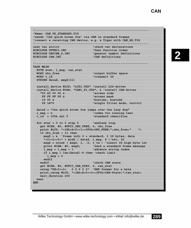
CAN
Wilke Technology GmbH • www.wilke-technology.com • eMail: [email protected]
2
289
'-----------------------------------------------------------------'Name: CAN_TX_STANDARD.TIG'sends 'the quick brown fox' via CAN in standard frames'connect a receiving CAN device, e.g. a Tiger with CAN_RX.TIG'-----------------------------------------------------------------user var strict 'check var declarations#INCLUDE UFUNC3.INC 'User Function Codes#INCLUDE DEFINE_A.INC 'general symbol definitions#INCLUDE CAN.INC 'CAN definitions
'-----------------------------------------------------------------TASK MAIN BYTE ever, i_msg, can_stat WORD obu_free 'output buffer space WORD t_id 'transmit ID STRING data$, msg$(11)
install_device #LCD, "LCD1.TDD" 'install LCD-driver install_device #CAN, "CAN1_K1.TDD", & 'install CAN-driver "50 A0 00 00 & 'access code FF FF FF FF & 'access mask 10 45 & 'bustim1, bustim2 08 1A"% 'single filter mode, outctrl
data$ = "the quick brown fox jumps over the lazy dog" i_msg = 0 'index for running text t_id = 155h shl 5 'standard identifier
for ever = 0 to 0 step 0 'endless loop get #CAN, #0, #UFCI_OBU_FREE, 0, obu_free print #LCD, "<1Bh>A<0><1><0F0h>OBU_FREE:";obu_free;" "; if obu_free > 11 then msg$ = & 'frame info 0 = standard, 2 ID bytes, data "<0><0><0>" + mid$ ( data$, i_msg, 8 )'nfo, ID msg$ = ntos$ ( msg$, 1, -2, t_id ) 'insert ID high byte 1st print #CAN, #0, msg$; 'send a standard frame message i_msg = i_msg + 1 'advance string index if i_msg > len(data$)-8 then 'check limit i_msg = 0 endif endif 'check CAN state get #CAN, #0, #UFCI_CAN_STAT, 0, can_stat using "UH<2><2> 0 0 0 0 2" 'HEX format for a byte print_using #LCD, "<1Bh>A<0><0><0F0h>CAN-State:";can_stat; wait_duration 200 nextEND

Device driver
Wilke Technology GmbH • www.wilke-technology.com • eMail: [email protected]
2
290
The following program shows a simple send example for extended frame CAN-messages.
Program example:
'-----------------------------------------------------------------'Name: CAN_TXEXTENDED.TIG'sends 'the quick brown fox' via CAN in extended frames'connect a receiving CAN device, e.g. a CAN-Tiger'-----------------------------------------------------------------user var strict 'check var declarations#INCLUDE UFUNC3.INC 'User Function Codes#INCLUDE DEFINE_A.INC 'general symbol definitions#INCLUDE CAN.INC 'CAN definitions
'-----------------------------------------------------------------TASK MAIN BYTE ever, i_msg, can_stat WORD obu_free 'output buffer space LONG t_id 'extended ID 4 bytes STRING data$, msg$(13)
install_device #LCD, "LCD1.TDD" 'install LCD-driver install_device #CAN, "CAN1_K1.TDD", & 'install CAN-driver "50 A0 00 00 & 'access code FF FF FF FF & 'access mask 10 45 & 'bustim1, bustim2 08 1A"% 'single filter mode, outctrl
data$ = "the quick brown fox jumps over the lazy dog" i_msg = 0 'index for running text t_id = 01733F055h shl 3 'extended identifier
for ever = 0 to 0 step 0 'endless loop get #CAN, #0, #UFCI_OBU_FREE, 0, obu_free print #LCD, "<1Bh>A<0><1><0F0h>OBU_FREE:";obu_free;" "; if obu_free > 13 then msg$ = & 'frame info 80h = exetended, 4 ID bytes, data "<80h><0><0><0><0>" + mid$ ( data$, i_msg, 8 ) msg$ = ntos$ ( msg$, 1, -4, t_id ) 'insert ID high byte 1st print #CAN, #0, msg$; 'send an extended frame message i_msg = i_msg + 1 'advance string index if i_msg > len(data$)-8 then ' check limit i_msg = 0 endif endif 'check CAN state get #CAN, #0, #UFCI_CAN_STAT, 0, can_stat using "UH<2><2> 0 0 0 0 2" 'HEX format for a byte print_using #LCD, "<1Bh>A<0><0><0F0h>CAN-State:";can_stat; wait_duration 200 nextEND

CAN
Wilke Technology GmbH • www.wilke-technology.com • eMail: [email protected]
2
291
Receive CAN messagesThe CAN device driver receives CAN messages and put these in the receive buffer.Reading out the receive buffer with the CAN device driver is a special process anddiffers from reading out other buffers (e.g. of the serial or parallel driver), since herethe messages in the buffer can contain further information in addition to the data. Themessages will always be read completely and processed according to the messagetype:
Two read modes read differently from the secondary addresses 0 and 1:
Sec.Adr.
0 The bytes in the CAN message will be read as they are in the buffer,including Frame-Format and ID-bytes.
1 Only data bytes will be read. Frame-Format and ID-bytes will beignored. The length information of partially read CAN messages will beautomatically corrected in the buffer .
Caution: the CAN-message must be read completely from the secondary address 0since otherwise the next read operation will not start with the Frame-Info byte of thenext CAN message.
Single messages containing 0...8 characters and whose frame format ID and Identifierprecede the data bytes are read out via the secondary address 0. The Frame-Info bytewill at first be read to determine whether this is a 'Standard-Frame’ or an 'extendedFrame’ and how many data bytes are contained therein. The ID-bytes which indicatethe application-specific type of message will then be read. The data bytes will then beread in.
The example program CAN_RX1.TIG reads the received messages from the buffer,distinguishes thereby between standard frames and extended frames and shows thesein a hexadecimal form.
Program example:

Device driver
Wilke Technology GmbH • www.wilke-technology.com • eMail: [email protected]
2
292
'-----------------------------------------------------------------'Name: CAN_RX1.TIG'receives unfiltered CAN messages and displays on LCD'knows standard and extended frame'displays also status'connect with a sending CAN device, e.g. a Tiger with CAN_TX1.TIG'-----------------------------------------------------------------user var strict 'check var declarations#INCLUDE UFUNC3.INC 'User Function Codes#INCLUDE DEFINE_A.INC 'general symbol definitions#INCLUDE CAN.INC 'CAN definitions
'-----------------------------------------------------------------TASK MAIN BYTE ever, frameformat, msg_len, can_stat WORD ibu_fill 'input buffer fill level LONG r_id 'received ID STRING msg$(8), data$(8)
install_device #LCD, "LCD1.TDD" 'install LCD-driver install_device #CAN, "CAN1_K1.TDD", & 'install CAN-driver "50 A0 00 00 & 'access code FF FF FF FF & 'access mask 10 45 & 'bustim1, bustim2 08 1A"% 'single filter mode, outctrl
print #LCD, "<1Bh>A<0><0><0F0h>STAT LEN ID";
for ever = 0 to 0 step 0 'endless loop get #CAN, #0, #UFCI_IBU_FILL, 0, ibu_fill print #LCD, "<1Bh>A<0><3><0F0h>IBU_FILL:";ibu_fill;" "; if ibu_fill > 2 then 'if at least one message get #CAN, #0, 1, frameformat 'get frame info byte msg_len = frameformat bitand 1111b 'length if frameformat bitand 80h = 0 then 'if standard frame get #CAN, #0, CAN_ID11_LEN, r_id 'get ID bytes r_id = byte_mirr ( r_id, 2 ) 'byte order for Tiger WORD r_id = r_id shr 5 'shift right bound using "UH<8><3> 0 0 0 0 3" 'to display ID else 'else it is extended frame get #CAN, #0, CAN_ID29_LEN, r_id 'get ID bytes r_id = byte_mirr ( r_id, 4 ) 'low byte 1st in LONG r_id = r_id shr 3 'shift right bound using "UH<8><8> 0 0 0 4 4" 'to display ID endif print_using #LCD, "<1Bh>A<9><1><0F0h>";r_id;
using "UH<1><1> 0 0 0 0 1" 'display length print_using #LCD, "<1Bh>A<6><1><0F0h>";msg_len; if msg_len > 0 then 'if contains data get #CAN, #0, msg_len, data$ 'get them and display msg$ = " " '8 spaces msg$ = stos$ ( msg$, 0, data$, msg_len )'prepare for LCD field

CAN
Wilke Technology GmbH • www.wilke-technology.com • eMail: [email protected]
2
293
print #LCD, "<1Bh>A<0><2><0F0h>data:";msg$; else print #LCD, ;" "; endif endif
get #CAN, #0, #UFCI_CAN_STAT, 0, can_stat 'CAN status using "UH<2><2> 0 0 0 0 2" 'HEX format for one byte print_using #LCD, "<1Bh>A<1><1><0F0h>";can_stat; nextEND

Device driver
Wilke Technology GmbH • www.wilke-technology.com • eMail: [email protected]
2
294
Data is read out via the secondary address 1 irrespective of the Frame-Format andIdentifier bytes. The device driver only reads the data bytes and ignores the Identifier.Incompletely read CAN messages keep their frame format and ID byte, the length iscorrected accordingly by the driver so that the next read operation again finds anintact CAN-message in the buffer.
Program example:
'-----------------------------------------------------------------'Name: CAN_RX2.TIG'receives CAN data and displays them, ignores IDs'displays data as text (send ASCII only)'displays also status'connect a sending CAN device, e.g. a Tiger with CAN_TXS.TIG'-----------------------------------------------------------------user var strict 'check var declarations#INCLUDE UFUNC3.INC 'User Function Codes#INCLUDE DEFINE_A.INC 'general symbol definitions#INCLUDE CAN.INC 'CAN definitions
'-----------------------------------------------------------------TASK MAIN BYTE ever, frameformat, msg_len, can_stat WORD ibu_fill 'output buffer fill level LONG r_id STRING id$(4), data$, line$
install_device #LCD, "LCD1.TDD" 'install LCD-driver install_device #CAN, "CAN1_K1.TDD", & 'install CAN-driver "50 A0 00 00 & 'access code FF FF FF FF & 'access mask 10 45 & 'bustim1, bustim2 08 1A"% 'single filter mode, outctrl
print #LCD, "<1Bh>A<0><0><0F0h>STAT LEN ID";
line$ = "" for ever = 0 to 0 step 0 'endless loop get #CAN, #0, #UFCI_IBU_FILL, 0, ibu_fill print #LCD, "<1Bh>A<0><3><0F0h>IBU_FILL:";ibu_fill;" "; get #CAN, #1, 0, data$ if data$ <> "" then line$ = line$ + data$ if len(line$) > 20 then 'if longer than LCD line line$ = right$ ( line$, 20 ) endif print #LCD, "<1Bh>A<0><2><0F0h>";line$; endif get #CAN, #0, #UFCI_CAN_STAT, 0, can_stat using "UH<2><2> 0 0 0 0 2" 'HEX format for a byte print_using #LCD, "<1Bh>A<1><1><0F0h>";can_stat; next

CAN
Wilke Technology GmbH • www.wilke-technology.com • eMail: [email protected]
2
295
END
Receipt of a 'Remote Transmission Request’ leads to a message which hasbeen especially provided for this purpose in the device driver being sent. The receivedCAN message would otherwise be treated as a CAN message without RemoteTransmission Request’.

Device driver
Wilke Technology GmbH • www.wilke-technology.com • eMail: [email protected]
2
296
Program example:
'-----------------------------------------------------------------'Name: CAN_RTR.TIG'prepares a RTR-message and sends then 2 different messages'in a loop.'RTR message and loop message have different IDs'connect a CAN device which uses a RTR message to get the'response, e.g. a CAN Tiger with CAN_RTRS.TIG'-----------------------------------------------------------------user var strict 'check var declarations#INCLUDE UFUNC3.INC 'User Function Codes#INCLUDE DEFINE_A.INC 'general symbol definitions#INCLUDE CAN.INC 'CAN definitions
'-----------------------------------------------------------------TASK MAIN BYTE ever 'endless loop STRING rtr_msg$(13)
install_device #LCD, "LCD1.TDD" 'install LCD-driver install_device #CAN, "CAN1_K1.TDD", & 'install CAN-driver "50 A0 00 00 & 'access code FF FF FF FF & 'access mask 10 45 & 'bustim1, bustim2 08 1A"% 'single filter mode, outctrl
rtr_msg$ = "<0><0FFh><0E0h>RTR-resp"'RTR response string as standardframe put #CAN, #2, rtr_msg$ 'prepare device driver print #LCD, "RTR-message prepared" 'now do something else for ever = 0 to 0 step 0 'endless loop wait_duration 3000 put #CAN, #0, "<0><0FFh><0C0h>abcdefgh" wait_duration 3000 put #CAN, #0, "<0><0FFh><080h>ijklmnop" nextEND
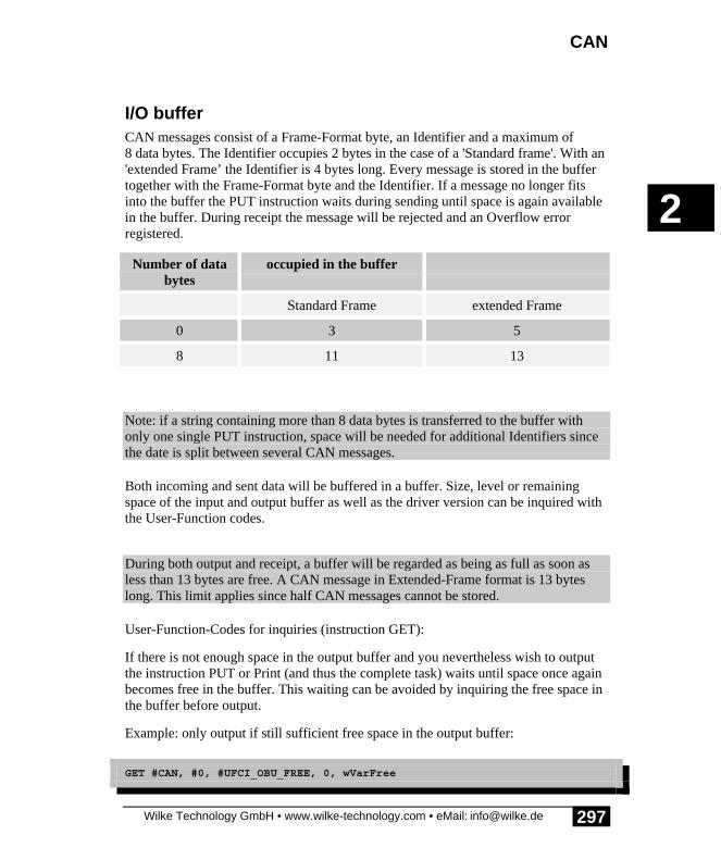
CAN
Wilke Technology GmbH • www.wilke-technology.com • eMail: [email protected]
2
297
I/O bufferCAN messages consist of a Frame-Format byte, an Identifier and a maximum of8 data bytes. The Identifier occupies 2 bytes in the case of a 'Standard frame'. With an'extended Frame’ the Identifier is 4 bytes long. Every message is stored in the buffertogether with the Frame-Format byte and the Identifier. If a message no longer fitsinto the buffer the PUT instruction waits during sending until space is again availablein the buffer. During receipt the message will be rejected and an Overflow errorregistered.
Number of databytes
occupied in the buffer
Standard Frame extended Frame
0 3 5
8 11 13
Note: if a string containing more than 8 data bytes is transferred to the buffer withonly one single PUT instruction, space will be needed for additional Identifiers sincethe date is split between several CAN messages.
Both incoming and sent data will be buffered in a buffer. Size, level or remainingspace of the input and output buffer as well as the driver version can be inquired withthe User-Function codes.
During both output and receipt, a buffer will be regarded as being as full as soon asless than 13 bytes are free. A CAN message in Extended-Frame format is 13 byteslong. This limit applies since half CAN messages cannot be stored.
User-Function-Codes for inquiries (instruction GET):
If there is not enough space in the output buffer and you nevertheless wish to outputthe instruction PUT or Print (and thus the complete task) waits until space once againbecomes free in the buffer. This waiting can be avoided by inquiring the free space inthe buffer before output.
Example: only output if still sufficient free space in the output buffer:
GET #CAN, #0, #UFCI_OBU_FREE, 0, wVarFree

Device driver
Wilke Technology GmbH • www.wilke-technology.com • eMail: [email protected]
2
298
IF wVarFree > (LEN(A$)) THEN PUT #CAN, #0, A$ENDIF
Example: check whether there is a message in the input buffer (the shortest possiblemessage is 3 bytes long):
GET #CAN, #0, #UFCI_IBU_FILL, 0, wVarFillIF wVarFill > 2 THEN ‘ lies die CAN-NachrichtENDIF

CAN
Wilke Technology GmbH • www.wilke-technology.com • eMail: [email protected]
2
299
Automatic bit rate detectionIf the driver is installed in the 'Listen-Only' mode it tries to automatically recognizethe bit rate. In the 'listen-only’ mode the CAN chip itself cannot send anything so thatthe otherwise familiar error telegrams will not be produced as long as the bit rate hasnot been recognized. Which bit rates are actually recognized can be set in a table. Ifno table is transferred during installation an internal table will be used.
The following prerequisites must be met to detect the bit rate:
• An operative bus with data traffic is assumed, i.e. there must be at least twoactive participants who send something.
• The table must contain the correct bit rate.
The bit rate detection starts with the first setting from the table, as a rule the highestpossible bit rate. No receive error occurs with the next data packet on the CAN bus ifthe bit rate is already correct. If a receive error does however occur, then the driverswitches to the next bit rate in the table and waits for a new CAN telegram. The driverwaits in every case until sufficient CAN telegrams have either enabled a recognitionof the bit rate or the table of possible values has been processed three times. If the bitrate wasn't recognized, the CAN device driver will not be installed. If CAN telegramsare only sent very rarely over the bus and the correct bit rate is only at the end of thetable, the detection takes accordingly longer. If the bit rate wasn't recognized, thedevice driver quits the 'listen-only’ mode.

Device driver
Wilke Technology GmbH • www.wilke-technology.com • eMail: [email protected]
2
300
The table contains the settings for the registers 'bustim0’ and 'bustim1’ in the CANchip. 2 bytes will therefore be needed for every setting. The table must contain at least4 bytes otherwise the internal table which contains the following values will be used
Program example:
'-----------------------------------------------------------------'Name: CAN_ABR.TIG'auto bitrate selection from pre-defined table'rest similar to CAN_RX1.TIG'connect with a CAN bus with sending devices'-----------------------------------------------------------------user var strict 'check var declarations#INCLUDE UFUNC3.INC 'User Function Codes#INCLUDE DEFINE_A.INC 'general symbol definitions#INCLUDE CAN.INC 'CAN definitions
'-----------------------------------------------------------------TASK MAIN BYTE ever, frameformat, msg_len, can_stat WORD ibu_fill 'input buffer fill level LONG r_id 'received ID STRING msg$(8), data$(8)
install_device #LCD, "LCD1.TDD" 'install LCD-driver print #LCD, "trying to find <10><13>CAN bitrate.<10><13>Please wait..." install_device #CAN, "CAN1_K1.TDD", & 'install CAN-driver "50 A0 00 00 & 'access code FF FF FF FF & 'access mask 00 00 & 'bustim1, bustim2 0A 1A & 'single filter + listen only, outctrl 00 43 & '1 Mbit here on table with bytes 00 5C & '500 kbit for bustim0 and bustim1 01 5C & '250 kbit for auto bitrate 03 5C & '125 kbit detection 04 5C & '100 kbit 09 5C & ' 50 kbit 10 45 & ' 49 kbit for SLIO: TSYNC + TSEG1 + TSEG2 = 10 0F 7F & ' 25 kbit 1F 7F"% ' 12.5 kbit
print #LCD, "<1>STAT LEN ID";
for ever = 0 to 0 step 0 'endless loop get #CAN, #0, #UFCI_IBU_FILL, 0, ibu_fill print #LCD, "<1Bh>A<0><3><0F0h>IBU_FILL:";ibu_fill;" "; if ibu_fill > 3 then 'if at least one message get #CAN, #0, 1, frameformat 'which frame format? msg_len = frameformat bitand 1111b if frameformat bitand 80h = 0 then 'if standard frame get #CAN, #0, CAN_ID11_LEN, r_id 'get ID bytes r_id = byte_mirr ( r_id, 2 ) 'byte order for Tiger WORD

CAN
Wilke Technology GmbH • www.wilke-technology.com • eMail: [email protected]
2
301
r_id = r_id shr 5 'shift right bound using "UH<8><3> 0 0 0 0 3" 'to display ID else 'else it is extended frame get #CAN, #0, CAN_ID29_LEN, r_id 'get ID bytes r_id = byte_mirr ( r_id, 4 ) 'low byte 1st in LONG r_id = r_id shr 3 'shift right bound using "UH<8><8> 0 0 0 4 4" 'to display ID endif print_using #LCD, "<1Bh>A<9><1><0F0h>";r_id;
using "UH<1><1> 0 0 0 0 1" 'display length print_using #LCD, "<1Bh>A<6><1><0F0h>";msg_len; if msg_len > 0 then 'if contains data get #CAN, #0, msg_len, data$ 'get them and display msg$ = " " '8 spaces msg$ = stos$ ( msg$, 0, data$, msg_len )'prepare for LCD field print #LCD, "<1Bh>A<0><2><0F0h>data:";msg$; else print #LCD, ;" RTR "; endif endif
get #CAN, #0, #UFCI_CAN_STAT, 0, can_stat 'CAN status using "UH<2><2> 0 0 0 0 2" 'HEX format for one byte print_using #LCD, "<1Bh>A<1><1><0F0h>";can_stat; nextEND

Device driver
Wilke Technology GmbH • www.wilke-technology.com • eMail: [email protected]
2
302
CAN-bus hardware connection exampleA terminating resistor of 120 ohms should be provided at each end of the line in thehardware. There is a DIP switch to activate or deactivate the terminating resistor onthe TCAN adapter for this purpose.
R1120R
R2
120R
VCC
total bus length up to 1000m
R30, or 16.5...140k
TxD1
GND2
VCC3
RxD4 Vref 5CANL6CANH 7Rs 8
U2PCA82C250/251
VCC
TxD1
GND2
VCC3
RxD4 Vref 5CANL 6CANH 7Rs 8PCA82C251
TxD 1
GND 2
VCC 3
RxD4
Vref5 CANL6 CANH7 Rs8
PCA82C251
TxD 1
GND 2
VCC 3
RxD 4Vref5 CANL6 CANH7 Rs8PCA82C251
BATT 45aVCC46a
Vref 43aAGND 44a
Alarm 38a
AN1 40a
L613a
AN0 39a
WAKE1a
L41/PC 37a
L602a
L40 36a
AN3 42a
L33 30a
L8620a
L42 35a
L8519a
AN2 41a
L8418a
L37 34a
L8317a
L36 33a
L8216a L35 32aL8115a
L34 31a
L8014a L73(PWM)13a
L90/TXD0 24a
L72(PWM)12a
L8721a
L7111a
Reset22a
L7010a
GND23a
L679a
L95/RTS029a
L668a
L92/CTS0 26a
L657a
L94/RXD1 28a
L646a
L93/TXD1 27a
L635a L624a
L91/RXD0 25a
1b2b3b4b5b6b7b8b9b
10b11b12b13b14b15b16b17b18b19b20b21b22b23b CAN_Tx0 24bCAN_Rx0 25bGND
26bCAN_Tx1 27bCAN_Rx1 28bVCC 29b30b31b32b33b34b35b36b37b38b39b40b41b42b43b44b45b46b
U?TCAN
Pay attention to the terminals of the bus with 120 ohm resistors.

CAN
Wilke Technology GmbH • www.wilke-technology.com • eMail: [email protected]
2
303
A short introduction to CANCAN is an abbreviation for Controllers Area Network. Originally, CAN wasdeveloped as a communications protocol to exchange information in motor vehicles.CAN is now just as common in automation engineering and domestic engineering.The basis for the CAN bus is a hardware which makes the connection to the CAN busand takes care of the actual message dispatch and message receipt, similar to a UARTat the RS 232 interface, though checksums, error control and repetition of themessages in the event of errors as well as bus arbitration and bus prioritisation. Thereare a number of manufacturers who have implemented the CAN-interface on theirprocessor and there are external CAN chips which can be connected to processorswhich do not have a CAN-interface 'on-board’.
Compact data packets are sent on the CAN bus, referred to in the following as CANmessages. A message consists of an Identifier and between 0 and 8 data bytes from auser point of view. There are two variants of the bit protocol on the bus, with 11-Bit-Identifiers in accordance with CAN 2.0A and with 29-Bit-Identifiers inaccordance with CAN 2.0B. Both variants exist next to each other, and both havetheir advantages and disadvantages. Modern chips support either CAN2.0B or at leastaccept the existence of 29 bit Identifiers on the (CAN2.0B passive).
Bus accesses and access priorities are defined by the CAN specification and arehandled completely by the CAN hardware. The application software places the CANmessage with a 'label' in the CAN send mail box. The label, or Identifier, is nothowever an address label but an identification of the contents of the CAN message,e.g. the temperature information from sensor 'A’, or the adjustment information forpressure controller 'X’. Any bus user for whose application the message is importantwill be programmed to accept this message . The sender cannot find out whether anyother node has accepted the message.
A receiving filter in the CAN hardware pre-filters the messages according to certaincriteria so that all messages reach the application. The biggest differences between thedifferent implementations of CAN hardware are in the receiving part. Both themanner of the filtration and the number of the messages which are saved in thereceive mail box are very different. An attempt is made to only allow those messagesthrough the filter which are important for the application.
So-called 'Remote Transmission Requests’ can be sent out on the CAN bus.The corresponding bus users are requested to respond with a specific message. Thus,for example, the request to report the 'Temperature Boiler 2' can appear on the bus.The applications in the single CAN nodes determine whether a response will be madeto such send requests and the contents of the response.

Device driver
Wilke Technology GmbH • www.wilke-technology.com • eMail: [email protected]
2
304
The bus accesses take place in a fixed time grid. All bus users synchronizethemselves with every bus access. The accesses take place at the same time. The idlelevel on the bus is the '1'. This level is not the dominant one. A '1' can be overwrittenby a '0', thus the term 'dominant' for the '0'. A bus access starts with a dominant '0'.This is followed by the '1' and '0' levels of the Identifier, starting with the highest-order bit. The lower priority bus users have '1'-bits in the higher-order bit positionsand can therefore be overwritten by the prioritized bus users with a '0'. As soon as auser is unable to place his '1' during a bus access he aborts the bus access to try againlater. This renewed trial is carried out automatically by the CAN hardware and neednot be programmed in the application, which knows nothing at all of this. Only if abus access proves impossible after a number of attempts, and the bus thereforeapparently permanently occupied by dominant users, will the application be able torecognize this status by an inquiry to the error registers of the CAN hardware.
The most concise differences to the majority of other networks and bus systems arecompared here:
Most other industrial bus systems CAN bus
Every user receives an address andmessages are given a destination address,sometimes together with an originaddress.
There aren't any addresses. The messagesare provided with a content declarationinstead of the address. The users haveprogrammable input filters which allowcertain messages to pass through.
An acknowledgement of receipt is oftenscheduled. The receiver then confirms thecorrect receipt of the transmission.
At the end of a message package theCAN hardware confirms that this hasbeen received correctly on the bus(Acknowledge). Whether any user has infact accepted the message is unknown.
Rules exist for the bus access so that twousers never use the bus simultaneously.
Several users can access the bus withCAN simultaneously. Prioritized usersreplace the others, who automaticallyaccess the bus later, during the access.The bus access is handled completely bythe CAN hardware.
CAN
Wilke Technology GmbH • www.wilke-technology.com • eMail: [email protected]
2
305
Special features of the BASIC-Tiger®-CAN moduleOther modules or units can be connected directly to the BASIC-Tiger®-CAN moduleif the distances are short, for example on the same PCB or at least in the same system-unit cover. An external bus driver is required for larger distances (e.g. PCA82C250).
The CAN hardware is supported by the CAN device drivers, available in a number ofvariants. The file names have the following meaning:
CAN_nn.TDD nn represents the buffer sizeR1: 256 bytesK1: 1 kByteK8: 8 kBytes
During installation, parameters can be specified which define the CAN messagefiltering properties and the bus timing. These parameters can be changed by UserFunction Codes during the running time.
The BASIC-Tiger®-CAN module supports CAN2.0B, in other words can send andreceive messages with 29-bit identifiers. As a rule messages are prepared togetherwith the Identifier in a string and then transferred to the CAN driver with a PUT orPRINT instruction. This buffers the messages if necessary. Received messages arefiled in the receive buffer of the device driver until they are read by BASIC withGET. The special format of the CAN messages has to be taken into account in everycase.

Device driver
Wilke Technology GmbH • www.wilke-technology.com • eMail: [email protected]
2
306
Error situationsIn the following, some error situations are listed and it will be shown how these canbe recognized .
Error Possible cause
What is seen on the Scope: a userpermanently and continually sends on thebus although the application only wantedto send a single message.
The sending user, or better: theirhardware, receives no Acknowledge fromanother bus user. The CAN hardwarethus sends the message again and again.
Possible reasons:
Only one active user is on the bus. Theothers are either unavailable, switched offor have not been initialized.
The bit rate of this participant doesn'tcorrespond with the bit rate of the otherbus users.
Messages which are safely sent don'tarrive.
Receive errors occur. Have the errorregister shown to be able to drawconclusions on the error.If the error registers are all right, it couldbe that the filters don not let the Identifierpass.
When sending, the error register is setimmediately.
The bus is possibly permanently occupiedby a higher prioritized user (overload) orthe bit rate is wrong.Is there another active user? At least onebus user must set the ACK bit.

CAN
Wilke Technology GmbH • www.wilke-technology.com • eMail: [email protected]
2
307
References to CAN[1] Wolfgang Lawrenz: CAN Controller Area Network, Grundlagen und Praxis.
Hüthig Verlag, 1994, ISBN 3-7785-2263-9
[2] Konrad Etschberger: CAN Controller Area Network, Grundlagen, Protokolle,Bausteine, Anwendungen. Verlag Hanser, 1994, ISBN 3-446-17596-2
[3] Bosch CAN Spezifikation Version 2.0 1991
[4] CiA: CAN in Automation e.V. Users Group, Am Weichselgarten 25, D-91058Erlangen, Germany; Tel: +49 9131 601091, Fax: +49 9131 601092
[5] SJA1000 data book as PDF-file on the Internet:http://www-eu3.semiconductors.com/pip/SJA1000
[6] P82C150 CAN-SLIO data book as PDF-file on the Internet:http://www-eu3.semiconductors.com/pip/P82C150
Extensive additional bibliographical references can be found in the books.
Device driver
Wilke Technology GmbH • www.wilke-technology.com • eMail: [email protected]
2
308
CAN-SLIO BoardTo be able to take the first steps in the CAN world, at least, or even better three bususers are needed. So either you have
• experience already with CAN and other bus users. You know this equipmentquite well.
• bought at least two TCAN modules, an adapter for the Plug & Play Lab andhave prepared a different hardware platform for the second TCAN module.
• bought the TCAN development packet, containing two boards with theCAN-SLIO modules from Philips as additional bus users.
This section contains:
• CAN-SLIO-Board• CAN-SLIO chip• Identifier for the SLIO• Automatic detection of bit rates• SLIO message format• Status byte - Data byte 1• Finding SLIOs on the bus• Some unusual features for interested parties• Remote Frames• Bit timing• Oscillator and calibration• Initialization• Sign-On-Message• Register overview• SLIO digital I/O's• SLIO analog outputs• Analog configuration• Starting the A/D conversion• Two SLIOs on one bus

CAN-SLIO Board
Wilke Technology GmbH • www.wilke-technology.com • eMail: [email protected]
2
309
CAN-SLIO BoardThe CAN-SLIO Board is an I/O device which is connected serially via the CAN busremote from the control unit. The main feature is the CAN-SLIO chip, which isdescribed in detail in the following sections (SLIO = Serial-Linked I/O). The boardcontains:
• a power supply with voltage regulator• the CAN driver chip• an add-on terminating resistor for the CAN bus• a DIP switch to set the Identifier• two potentiometers to set 2 analog voltages• a simple filter circuit for the quasi-analog outputs• 2 N fets and 2 P-FETs for random use• terminal screws for 16 digital I/O's• terminal screws for the CAN bus• terminal screws for the power supply, if the socket isn't used

Device driver
Wilke Technology GmbH • www.wilke-technology.com • eMail: [email protected]
2
310
Technical data for the CAN-SLIO board:
Outsidemeasurements/weight:
approx. 100 x 85 x 27 mm/approx. 75 g
Power supply 8V...24V / approx. 22 mA (unloaded I/O)
Load capacity of the I/O pins ±4 mA, all pins together < 200 mW
Reset Power-ON Reset on the board by R-C link
Temperature range -40...+85° C
A/D input Resolution 6...7 bit, up to 6 channels via analogswitch
D/A outputs 2 DPM (distributed pulse modulated) resolution 10-bit repeat frequency 1024 bit times
To put the board into operation, connect it to a CAN-bus with a quartz-controlled user(screw terminals 'H' and 'L'). Such a user can be e.g. a BASIC-Tiger®-CAN module onthe CAN adapter of the Plug & Play Lab. If the SLIO board is at the physical end ofthe bus switch the DIP switch next to the terminal screw to 'ON' to connect theterminating resistor. If the board isn't at the bus end, turn the DIP switch off.
Wire further hardware which is to be connected to the I/O pins.
Set the desired ID bits with the 4 DIP switches. All bus users should have a clearIdentifier which is unique in the bus system.
Load one of the example programs into the TCAN 4/4 module. The basic exampleprogram is 'SLIO_FIND1.TIG', which finds the SLIO chip. This also take care ofautomatic bit rate detection and permanent resynchronization of the SLIO chip.

CAN-SLIO Board
Wilke Technology GmbH • www.wilke-technology.com • eMail: [email protected]
2
311
CAN-SLIO chipThe CAN-SLIO chip P82C150 is a serially connected I/O chip (SLIO = Serial-LinkedI/O) whose register can be written via the CAN bus. The SLIO chip supports theprotocol specifications 2.0A and 2.0B(passive). Cuts in the bit timing exist due to theautomatic bit rate detection, provided this is used. In a system with P82C150 nodeswith automatic bit rates detection at least one active CAN node must be with quartz.
A SLIO chip which must recognize the bit rate itself is located on the CAN-SLIOboard. This is possible in the range of bit times from of 8 µ sec to approx. 50 µ sec.The following examples are set to a bit time of approx. 22 µsec.
Identifier of the SLIOThe CAN-SLIO processes 11 bit Identifiers. 29 bit Identifiers are ignored. 4 bits ofthe receive mask are read in after the reset of the port pins P0...P3. This port pin canbe used as an I/O pin after this. Thus, up to 16 SLIO chips can be operated on one bus(if using an external clock this number is reduced to 8). Every SLIO chip uses2 Identifiers which differ in the lowest bit. The higher priority is reserved for messagereception (bit ID.0=0).
ID.10 ID.9 ID.8 ID.7 ID.6 ID.5 ID.4 ID.3 ID.2 ID.1 ID.0
0 1 P3 1 0 P2 P1 P0 1 0 DIR
DIR 0: Messages which are sent by the Host to the SLIO chip (writeregister, configuration).1: Messages which are sent by the SLIO chip to the Host (readregister, RTR).
P0, P1, P2, P3 Programmable ID bits which are read after the reset of 1the pinP0...P3.
Automatic bit rate detectionThe SLIO chip is in the Sleep mode after switching on or a Reset. The internaloscillator is stopped and all output drivers are de-activated. It switches to the'differential mode' after the first dominant bit on the bus. The bit rate must first berecognized to make the chip available on the CAN bus. For this purpose the SLIOchip needs a certain bit pattern on the bus. This bit pattern creates a certain messagewith defined Identifier and defined data bytes. The same message is later to re-
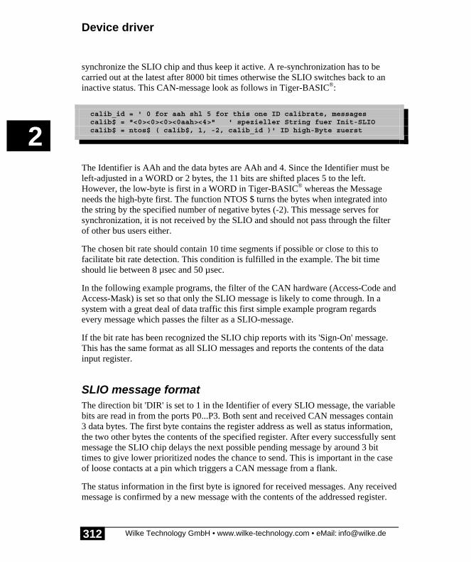
Device driver
Wilke Technology GmbH • www.wilke-technology.com • eMail: [email protected]
2
312
synchronize the SLIO chip and thus keep it active. A re-synchronization has to becarried out at the latest after 8000 bit times otherwise the SLIO switches back to aninactive status. This CAN-message look as follows in Tiger-BASIC®:
calib_id = ' 0 for aah shl 5 for this one ID calibrate, messages calib$ = "<0><0><0><0aah><4>" ' spezieller String fuer Init-SLIO calib$ = ntos$ ( calib$, 1, -2, calib_id )' ID high-Byte zuerst
The Identifier is AAh and the data bytes are AAh and 4. Since the Identifier must beleft-adjusted in a WORD or 2 bytes, the 11 bits are shifted places 5 to the left.However, the low-byte is first in a WORD in Tiger-BASIC® whereas the Messageneeds the high-byte first. The function NTOS $ turns the bytes when integrated intothe string by the specified number of negative bytes (-2). This message serves forsynchronization, it is not received by the SLIO and should not pass through the filterof other bus users either.
The chosen bit rate should contain 10 time segments if possible or close to this tofacilitate bit rate detection. This condition is fulfilled in the example. The bit timeshould lie between 8 µsec and 50 µsec.
In the following example programs, the filter of the CAN hardware (Access-Code andAccess-Mask) is set so that only the SLIO message is likely to come through. In asystem with a great deal of data traffic this first simple example program regardsevery message which passes the filter as a SLIO-message.
If the bit rate has been recognized the SLIO chip reports with its 'Sign-On' message.This has the same format as all SLIO messages and reports the contents of the datainput register.
SLIO message formatThe direction bit 'DIR' is set to 1 in the Identifier of every SLIO message, the variablebits are read in from the ports P0...P3. Both sent and received CAN messages contain3 data bytes. The first byte contains the register address as well as status information,the two other bytes the contents of the specified register. After every successfully sentmessage the SLIO chip delays the next possible pending message by around 3 bittimes to give lower prioritized nodes the chance to send. This is important in the caseof loose contacts at a pin which triggers a CAN message from a flank.
The status information in the first byte is ignored for received messages. Any receivedmessage is confirmed by a new message with the contents of the addressed register.

CAN-SLIO Board
Wilke Technology GmbH • www.wilke-technology.com • eMail: [email protected]
2
313
(Exception: sees analog configuration). If the SLIO chip has received a CAN messageis responds with a message containing the 4 status bits, the previously receivedregister address as well as the contents of the register. (Exceptions see A/Dconfiguration). Read registers are read in this way and the write process is confirmedby write registers.
Status byte - Data-Byte 1
Status Register Address
RSTD EW BM1 BM0 A3 A2 A1 A0
RSTD 1: Sign-On message0: Other message
EW 1: 'error warning limit' (32) reached. Bit is set if the ReceiveError Counter or the Transmit Error Counter has exceeded thevalue 32. Always 1 in the 'Sign-On' message.
BM0, BM1 Bus mode status bits (see below).
A0...A3 Register address. Determines which internal SLIO register is tobe read or written.
The bus mode is shown in the status bits BM0 and BM1:
Bus mode Bits Reception Level Transmission
BM1 BM0 recessive dominant Tx1 Tx0
0=differential 0 0 Rx0>Rx1 Rx0<Rx1 enabled enabled
1=one wireRx1
0 1 Rx1<REF Rx1>REF enabled enabled
2=one wireRx0
1 0 Rx0>REF Rx0<REF disabled enabled
3=sleep 1 1 Rx0>REFand
Rx1<REF
Rx0<REFand
Rx1>REF
disabled enabled
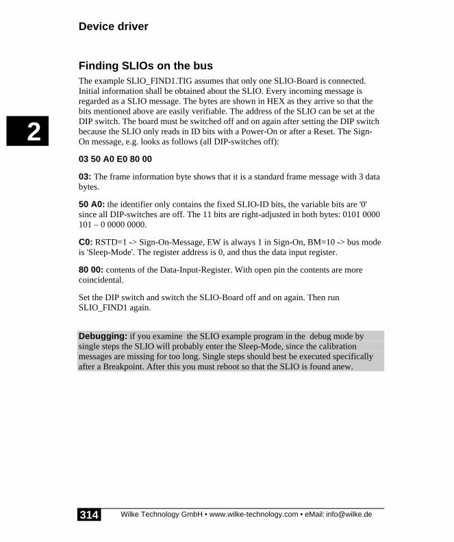
Device driver
Wilke Technology GmbH • www.wilke-technology.com • eMail: [email protected]
2
314
Finding SLIOs on the busThe example SLIO_FIND1.TIG assumes that only one SLIO-Board is connected.Initial information shall be obtained about the SLIO. Every incoming message isregarded as a SLIO message. The bytes are shown in HEX as they arrive so that thebits mentioned above are easily verifiable. The address of the SLIO can be set at theDIP switch. The board must be switched off and on again after setting the DIP switchbecause the SLIO only reads in ID bits with a Power-On or after a Reset. The Sign-On message, e.g. looks as follows (all DIP-switches off):
03 50 A0 E0 80 00
03: The frame information byte shows that it is a standard frame message with 3 databytes.
50 A0: the identifier only contains the fixed SLIO-ID bits, the variable bits are '0'since all DIP-switches are off. The 11 bits are right-adjusted in both bytes: 0101 0000101 – 0 0000 0000.
C0: RSTD=1 -> Sign-On-Message, EW is always 1 in Sign-On, BM=10 -> bus modeis 'Sleep-Mode'. The register address is 0, and thus the data input register.
80 00: contents of the Data-Input-Register. With open pin the contents are morecoincidental.
Set the DIP switch and switch the SLIO-Board off and on again. Then runSLIO_FIND1 again.
Debugging: if you examine the SLIO example program in the debug mode bysingle steps the SLIO will probably enter the Sleep-Mode, since the calibrationmessages are missing for too long. Single steps should best be executed specificallyafter a Breakpoint. After this you must reboot so that the SLIO is found anew.

CAN-SLIO Board
Wilke Technology GmbH • www.wilke-technology.com • eMail: [email protected]
2
315
Program example:
'-----------------------------------------------------------------'Name: SLIO_FIND1.TIG'finds SLIO chip(s) or reports an error.'connect CAN-SLIO-Boards with different addresses'-----------------------------------------------------------------user var strict 'check var declarations#INCLUDE UFUNC3.INC 'User Function Codes#INCLUDE DEFINE_A.INC 'general symbol definitions#INCLUDE CAN.INC 'CAN definitions#INCLUDE CANSLIO.INC 'definitions for CAN SLIO chip
#define NOT_READY 0 'SLIO status#define READY 1
'ID bit positions#define ID_SLIO1 00000000000b 'ID bit setting of this SLIO
BYTE slio_statWORD slio1_id, calib_idLONG ac_code, ac_maskSTRING id$(4), calib$(5)STRING slio1_dout$(6), slio1_doe$(6)
'-----------------------------------------------------------------TASK MAIN BYTE ever WORD fi STRING id1$, c$
install_device #LCD, "LCD1.TDD"
'waiting for code of SLIO but filtering out the keep-alive code'these bits are left bound in the 32-bit code and mask'010100001010 <- fix SLIO bits'00100111000 <- filter: 1:don't care, 0: bit must fit
install_device #CAN, "CAN1_K1.TDD", & "50 A0 00 00 & 'access code 27 1F FF FF & 'access mask 10 45 & 'bit time 20usec (poss.: 8...50usec) 08 1A"% 'single filter mode, outctrl
calib_id = 0aah shl 5 'ID of calibration messages calib$ = "<0><0><0><0aah><4>" 'special string to init the SLIO calib$ = ntos$ ( calib$, 1, -2, calib_id )'insert ID high byte 1st
'-----------------------------------------------------------------'sends calibration messages and waits for'(filtered) SLIO messages as response
print #LCD, "trying to find SLIO";

Device driver
Wilke Technology GmbH • www.wilke-technology.com • eMail: [email protected]
2
316
slio_stat = NOT_READY while slio_stat = NOT_READY 'check SLIO state put #CAN, calib$ 'calibration message on the bus wait_duration 50 get #CAN, #0, #UFCI_IBU_FILL, 2, fi if fi > 5 then 'if at least one message is there print #LCD, "<1bh>A<0><1><0f0h>"; 'set cursor while fi > 0 'read buffer get #CAN, 1, c$ using "UH<2><2> 0 0 0 0 2" 'and show HEX print_using #LCD, asc(c$);" "; get #CAN, #0, #UFCI_IBU_FILL, 2, fi 'more? endwhile print #LCD, "<1bh>A<0><2><0f0h>SLIO found"; slio_stat = READY endif endwhile
for ever = 0 to 0 step 0 'endless loop nextEND
A somewhat more complicated subroutine 'be found_slios' which takes furtherconditions into account has been written for the following examples:
There can be a number of SLIOs on the bus.
There may still be bus users who have no SLIO.
There may be no SLIO at all but the program should still run.
The SLIOs need regular calibration bit patterns on the CAN bus otherwise they enterthe Sleep mode and the outputs become inactive.
The subroutine waits a second to give all SLIOs which may be present the possibilityto send their Sign-On messages and also to be taken into account by the application.On the other hand, the system does not wait any longer because it could be that noSLIO reports. This example reports this fact and ends the main programme.
The received messages are checked to see whether they also originate from a SLIO.No other bus user may have one of the possible 16 SLIO IDs. Messages others thanSLIO messages are only read out from the buffer and rejected in the detection phase.
The task 'keep_alive’ sends the calibration message to wake up the SLIOs and thenkeep them active. A calibration message should occur on the bus at the latest after8000 bit times. They are not received by any user, they only generate a bit pattern

CAN-SLIO Board
Wilke Technology GmbH • www.wilke-technology.com • eMail: [email protected]
2
317
necessary for the re-synchronization of the SLIOs. During the detection phase thecalibration message is sent slightly more often.
The task 'keep_alive’ also sends messages wherever this is necessary. This is notnecessary in this example since only the detection is to be demonstrated. The otherexamples do, however, use the output of the task 'keep_alive' through the variable'can_out$'.
If you now wish to understand this example in detail you can regard this subroutine as'Black-box' in the following examples.
Debugging: if you examine the SLIO example program in the debug mode bysingle steps the SLIO will probably enter the Sleep-Mode, since the calibrationmessages are missing for too long. Single steps should best be executed specificallyafter a Breakpoint. After this you must reboot so that the SLIO is found anew.

Device driver
Wilke Technology GmbH • www.wilke-technology.com • eMail: [email protected]
2
318
Program example:
'-----------------------------------------------------------------'Name: SLIO_FIND2.TIG'finds SLIO chip(s) or reports an error.'connect CAN-SLIO-Boards with different addresses'-----------------------------------------------------------------user var strict 'check var declarations#INCLUDE UFUNC3.INC 'User Function Codes#INCLUDE DEFINE_A.INC 'general symbol definitions#INCLUDE CAN.INC 'CAN definitions#INCLUDE CANSLIO.INC 'definitions for CAN SLIO chip
#define ALIVETIME 50 'approx. 2200 * 22usec#define SLIOSLOT 10000 'msec time to sign on (SLIOs)
'ID bit positions#define ID_SLIO1 00000000000b 'ID bit setting of this SLIO
'gloabal variablesBYTE no_of_slios 'counter for SLIOs in systemWORD slio1_id, calib_id 'ID of SLIO and calib. messageLONG ac_code, ac_mask 'access code and access maskLONG slio_equip '1 bit for each SLIOLONG alive_wait 'half wait time in 'keep_alive'STRING calib$(5) 'calibration messageSTRING can_out$(13) 'message to be sent
'-----------------------------------------------------------------TASK MAIN BYTE ever 'endless loop WORD fi 'buffer fill level STRING c$
install_device #LCD, "LCD1.TDD" 'install LCD driver
'waiting for code of SLIO but filtering out the keep-alive code'these bits are left bound in the 32-bit code and mask'010100001010 <- fix SLIO bits (50Ah)'00100111000 <- filter: 1:don't care, 0: bit must fit (271h)
install_device #CAN, "CAN1_K1.TDD", & "50 A0 00 00 & 'access code 27 1F FF FF & 'access mask 10 45 & 'bit time 20usec (poss.: 8...50usec) 08 1A"% 'single filter mode, outctrl
call find_slios 'generates a list of all SLIOs 'of the system if slio_equip = 0 then 'if found no SLIO goto no_slio_found 'then abort program else print #LCD, "<1Bh>A<0><2><0F0h>";no_of_slios;" SLIOs found";

CAN-SLIO Board
Wilke Technology GmbH • www.wilke-technology.com • eMail: [email protected]
2
319
endif for ever = 0 to 0 step 0 'endless loop print #LCD, "<1bh>A<0><3><0f0h>task main running" next
no_slio_found: stop_task keep_alive print #LCD, "<1>no SLIO found" print #LCD, "program terminated"END
'-----------------------------------------------------------------'Sends calibration messages and waits for'(filtered) SLIO messages as response'Within a certain time slot all SLIOs must have sent their'sign_on messages. Filter should be set by main program.'Non-SLIO messages or extended frames are just removed'from the buffer.'-----------------------------------------------------------------SUB find_slios () BYTE ever, i 'loop variables WORD ibu_fill 'input buffer fill length BYTE frameformat, msg_len 'frame format and length of message LONG r_id LONG t STRING msg$(13), data$(8) 'message and data
slio_equip = 0 'begin with 'no SLIO' no_of_slios = 0 calib_id = 0aah shl 5 'ID of calibration messages calib$ = "<0><0><0><0aah><4>" 'special string to init the SLIO calib$ = ntos$ ( calib$, 1, -2, calib_id )'insert ID high byte 1st can_out$ = "" 'must be initialized
alive_wait = ALIVETIME/2 'in init phase shorter run_task keep_alive 'sends calibration messages 'and keeps SLIOs synchronized print #LCD, "trying to find SLIOs"; t = ticks() 'begin of time slot while diff_ticks ( t ) < SLIOSLOT 'within the time slotrx_cont: wait_duration 50 get #CAN, #0, #UFCI_IBU_FILL, 0, ibu_fill if ibu_fill > 2 then 'if at least one message get #CAN, #0, 1, frameformat 'get frame info byte msg_len = frameformat bitand 1111b 'length if frameformat bitand 80h = 0 then 'if standard frame get #CAN, #0, CAN_ID11_LEN, r_id 'get ID bytes r_id = byte_mirr ( r_id, 2 ) r_id = r_id shr 5 'if no SLIO message if r_id bitand SLIO_ID_IMASK <> SLIO_FIX_ID then 'free buffer if msg_len > 0 then 'if contains data: throw away

Device driver
Wilke Technology GmbH • www.wilke-technology.com • eMail: [email protected]
2
320
get #CAN, #0, msg_len, data$'get them and free the buffer endif goto rx_cont 'wait for next message endif else 'else it is extended frame get #CAN, #0, CAN_ID29_LEN, r_id'and no SLIO message if msg_len > 0 then 'if contains data get #CAN, #0, msg_len, data$ 'get them and free the buffer endif goto rx_cont 'wait for next message endif'-----------------------------------------------------------------'here: it was a SLIO message. Find out its address'and enter into bit list
r_id = r_id bitand SLIO_ID_MASK 'settable SLIO address bits if bit ( r_id, 8 ) = 1 then 'if P8 set then r_id = ( r_id bitand 111000b ) + 40h endif r_id = r_id shr 3 'shift away lower 3 ID bits set_bit slio_equip, r_id 'set bit number in list print #LCD, "<1Bh>A<0><1><0F0h>SLIO ";r_id;" found" no_of_slios = no_of_slios + 1 'count the found SLIO 'ignore here info in data bytes if msg_len > 0 then 'if contains data get #CAN, #0, msg_len, data$ 'get them out of the buffer'' using "UH<2><2> 0.0.0.0.2" ' format for HEX output'' for i = 0 to len ( data$ ) - 1 all bytes of the string'' print_using #LCD, asc ( mid$ ( data$, i, 1 ) );' in HEX'' next endif endif endwhile alive_wait = ALIVETIME 'normal wait time 'keep_alive'END
'-----------------------------------------------------------------'Sends calibration messages in order to keep the SLIO synchronized.'After max. 8000 bit times a calibration message must be sent.
'If can_out$ is not empty it will be sent and set to empty again
'-----------------------------------------------------------------TASK keep_alive BYTE ever
for ever = 0 to 0 step 0 'endless loop put #CAN, calib$ 'send calibration message wait_duration alive_wait 'wait max 8000 bit times if can_out$ <> "" then put #CAN, can_out$ 'send message can_out$ = "" 'empty = sent endif wait_duration alive_wait 'wait max 8000 bit times

CAN-SLIO Board
Wilke Technology GmbH • www.wilke-technology.com • eMail: [email protected]
2
321
nextEND

Device driver
Wilke Technology GmbH • www.wilke-technology.com • eMail: [email protected]
2
322
Some special features for interested partiesSo as not to unnecessarily make the rather complicated topic more difficult in theintroduction, certain special weren't mentioned there.
Remote FramesRemote-Frames can be used to call remote messages via the CAN bus, in other wordsinquire peak values and obtain information. Although the SLIO answers also withouta set RTR bit, the bit may of course be set. Received Remote Frames must, however,set the DLC (data length code) to 3 or else will they be ignored. The answer alwayscontains the bytes of the data input register.
Bit-TimingThe nominal bit time of the CAN-SLIO chip is subdivided into 10 bit segments. Thesynchronization segment and the Propagation Time Segment initialize the bit. Phase 1follows with 4 segments, at the end of which the bit is scanned. Phase 2 is also4 segments long. This timing structure is not alterable. The quartz-controlled hostshould also be set so that the bit time is subdivided into 10 segments.
1 bit time
BT1 BT2 BT3 BT4 BT5 BT6 BT7 BT8 BT9 BT10
Sync Prop phase_1 phase_2
Oscillator and calibrationThe SLIO chip has an internal R-C oscillator which is automatically calibrated by theCAN messages on the bus. During the start every message is used to adjust the bittime. A certain bit pattern on the bus is necessary for an exact calibration. Example ofa suitable calibration message ( | = Stuffbit, the important bits are underlined):
SOF arbitration controlfield
data byte1
data byte2
CRC field
0 000101010100 000|010 10101010 0000|0100 000|01011100000|0
Identifier is AAh, two data bytes with the values AAh, 4 are contained in the message.
CAN-SLIO Board
Wilke Technology GmbH • www.wilke-technology.com • eMail: [email protected]
2
323
InitializationAll outputs of the CAN_SLIO in the reset phase (RST = high) are high-impedance.The 4 ID-bits are read in at the pins P0...P3.. The other ID bits are permanently fixed .In accordance with the CAN definition, two nodes may not use the same Identifier. ACAN-SLIO has one of the 16 possible bit combinations.
Reset state:
Status bits Identifier bits
RSTD = 1 ID.3 equal to P0
EW = 1 ID.4 equal to P1
BM1 = 0 ID.5 equal to P2
BM0 = 0 ID.8 equal to P3
The SLIO-chip must have received at least 3 news messages on the bus before theBus mode is changed. The first message is used to measure the bit time if the messagecontains a sequence '010101'. The 2nd and 3rd message will not be confirmed with anACK despite correct reception. The SLIO chip sends its 'sign-on' message after 3messages have been received correctly.
The CAN-SLIO chip also evaluates messages as having been received correctly if anError Passive Frame follows these due to the missing ACK. This situation arises if aHost cooperates with one or more CAN -SLIOs and the SLIOs are not yet calibrated.
Sign-On MessageThis special message is sent by every CAN-SLIO once after the chip has beencalibrated. The ready status of the node is indicated by this.
The Sign-On message reports the contents of the data input register and differs fromother messages by the set bit RSTD:
RSTD = 1: Sign-On messageRSDT = 0: Other messages
Note: The EW-bit is set in the Sign-On message. Nevertheless, the status and theError counter are reset to 0.

Device driver
Wilke Technology GmbH • www.wilke-technology.com • eMail: [email protected]
2
324
Register overviewRegisteraddress
Register name Function
0 Data input Contains the input levels of the Pins P0 to P15
1 Event Positive Edge Activates the deposit of a message when the bit isset with a positive flank at the pins P0...P15
2 Event Negative Edge Activates the deposit of a message when the bit isset with a negative flank at the pins P0...P15
3 Data output Contains the output levels of the Pins P0 to P15
4 Output Enable Activates the output driver when the bit is set atthe pins P0...P15
5 Analog Configuration Bits 0...4: without functionBits 5,6,7: position of analog switchBits 8,9,10: position of monitoring switchBit 11: without functionBits 12,13,14: result of analog comparatorsBits 15: starts A/D conversion if set
6 DPM1 Distributed Pulse Modulation. Contains the 10-Bitanalog value in the bits 6...15. Quasi-Analogoutput 1 at pin P10
7 DPM2 Distributed Pulse Modulation. Contains the 10-Bitanalog value in the bits 6...15. Quasi-Analogoutput 2 at pin P4
8 A/D conversion Contains the 10 bit result of the A/D conversion inthe bits 6...15

CAN-SLIO Board
Wilke Technology GmbH • www.wilke-technology.com • eMail: [email protected]
2
325
SLIO Digital I/O'sThe SLIO chip provides 16 pins, which can work as digital inputs or digital outputs.Some pins can however assume other functions, e.g. analog inputs, analog outputs aswell as reading in the ID-bit after the Reset. Some pins are therefore speciallyconnected on the CAN-SLIO board and not simply led onto the pin contact strip:
P0...P3 have pull-up resistors of 47k and pull-down resistors of 4k7 toadjust the ID bits with the DIP switch.
P4, P10 are possible quasi-analog outputs and led over simple R-Cfilters.
P15, P16 are connected via a 100k resistance and P15 has a 3.3nFcondenser against mass. This allocation is necessary to use P15as analog-in.
Digital inputs: All pins are inputs with approx. 500 k input resistance after a Resetor Power-On. The level statuses are reflected in the 'Data-in’ register (address 0). Theregister Output-Enable' (address 4) has a bit for every port pin which is set to '0' andthus deactivates the output driver.
Digital outputs: The register 'Output-Enable' (address 4) has a bit for every port pinwhich activates the output driver when set to '1'. The register must be describedexplicitly to activate output pins. The bit pattern for all activated outputs is written tothe register 'Data-output' (address 3).
Events: CAN-messages are sent automatically if the bit is set for the desired pin inthe registers 'Event Positive Edge’ and/or 'Event Negative Edge’ and correspondingflank appears.
The following example program sets all port pins as outputs and switches themalternately to high and low. The subroutine 'find_slios' together with the task'keep_alive' to find the SLIO(s) as described under 'find SLIOs on the bus'. TheIdentifier of the SLIO found last is used. The ports become outputs by setting all bitsto '1' in the 'Output-Enable’ register. 0000 and FFFFh are then written alternately inthe 'Data-output' register. Since the SLIO responds with a confirmation message whenit has received the message the task 'show_slio' outputs this SLIO message and theIdentifier on the LCD in HEX. Foreign messages, which automatically includeextended frames, are rejected by 'show_slio', only the receive buffer is cleared.
Debugging: if you examine the SLIO example program in the debug mode by singlesteps the SLIO will probably enter the Sleep-Mode, since the calibration messages are

Device driver
Wilke Technology GmbH • www.wilke-technology.com • eMail: [email protected]
2
326
missing for too long. Single steps should best be executed specifically after aBreakpoint. After this you must reboot so that the SLIO is found anew.

CAN-SLIO Board
Wilke Technology GmbH • www.wilke-technology.com • eMail: [email protected]
2
327
Program example:
'-----------------------------------------------------------------'Name: SLIO_HIGH_LOW.TIG'blinks all I/O pins of SLIO 'high-low''connect CAN-SLIO-Board, all DIP-switches off'-----------------------------------------------------------------user var strict 'check var declarations#INCLUDE UFUNC3.INC 'User Function Codes#INCLUDE DEFINE_A.INC 'general symbol definitions#INCLUDE CAN.INC 'CAN definitions#INCLUDE CANSLIO.INC 'definitions for CAN SLIO chip
#define ALIVETIME 50 'wait approx. 2500 * 20usec#define SLIOSLOT 1000 'msec time to sign on (SLIOs)
#define NOT_READY 0 'SLIO status#define READY 1
'ID bit positions#define ID_SLIO1 00000000000b 'ID bit setting of this SLIO
'gloabal variablesBYTE no_of_slios 'counter for SLIOs in systemBYTE slio_statWORD slio1_id, calib_id 'ID of SLIO and calib. messageLONG ac_code, ac_mask 'access code and access maskLONG slio_equip '1 bit for each SLIOLONG alive_wait 'half wait time in 'keep_alive'STRING calib$(5) 'calibration messageSTRING slio1_dout$(6), slio1_doe$(6)'data out, data out enableSTRING can_out$(13) 'message to be sent
'-----------------------------------------------------------------TASK MAIN BYTE ever 'endless loop WORD fi 'buffer fill level
install_device #LCD, "LCD1.TDD"
'waiting for code of SLIO but filtering out the keep-alive code'these bits are left bound in the 32-bit code and mask'010100001010 <- fix SLIO bits (50Ah)'00100111000 <- filter: 1:don't care, 0: bit must fit (271h)
install_device #CAN, "CAN1_K1.TDD", & "50 A0 00 00 & 'access code 27 1F FF FF & 'access mask 10 45 & 'bit time 22usec (poss.: 8...50usec) 08 1A"% 'single filter mode, outctrl
'ID of this SLIO: 0=standard frame '+ 2 ID bytes shifted by 5

Device driver
Wilke Technology GmbH • www.wilke-technology.com • eMail: [email protected]
2
328
' slio1_id = (SLIO_FIX_ID bitor ID_SLIO1) shl 5 ' SLIO-Identifier'slio1_id will be last found SLIO calib_id = 0aah shl 5 'ID of calibration messages can_out$ = "" 'must be initialized
call find_slios 'generates a list of all SLIOs 'of the system if slio_equip = 0 then 'if found no SLIO goto no_slio_found 'then abort program else print #LCD, "<1Bh>A<0><2><0F0h>";no_of_slios;" SLIOs found"; endif wait_duration 1500 print #LCD, "<1>";
run_task show_slio 'shows what SLIO(s) send
slio1_doe$ = "<0><0><0><4><0FFh><0FFh>" 'SLIO_OUT_ENABLE slio1_doe$ = ntos$ ( slio1_doe$, 1, -2, slio1_id)'insert ID high byte1st can_out$ = slio1_doe$ wait_duration 100 for ever = 0 to 0 step 0 'endless loop ---------- slio1_dout$ = "<0><0><0><3><0FFh><0FFh>" 'SLIO_DATA_OUT slio1_dout$ = ntos$ ( slio1_dout$, 1, -2, slio1_id )'zuerst insert IDhigh byte 1st can_out$ = slio1_dout$ wait_duration 100 slio1_dout$ = "<0><0><0><3><0><0>" slio1_dout$ = ntos$ ( slio1_dout$, 1, -2, slio1_id )'insert ID can_out$ = slio1_dout$ wait_duration 100 next 'endless loop ----------
no_slio_found: 'no SLIO found stop_task keep_alive print #LCD, "<1>no SLIO found" print #LCD, "program terminated"END
'-----------------------------------------------------------------'Displays content of SLIO messages'Line 1 on LCD: ID'Line 2 on LCD: data bytes in HEX'-----------------------------------------------------------------TASK show_slio BYTE ever, i 'loop variables WORD ibu_fill 'input buffer fill length BYTE frameformat, msg_len 'frame format and length ofmessage LONG r_id 'receive ID STRING msg$(13), data$(8) 'message and data
for ever = 0 to 0 step 0 'endless looprx_cont:

CAN-SLIO Board
Wilke Technology GmbH • www.wilke-technology.com • eMail: [email protected]
2
329
get #CAN, #0, #UFCI_IBU_FILL, 0, ibu_fill if ibu_fill > 2 then 'if at least one message get #CAN, #0, 1, frameformat 'get frame info byte msg_len = frameformat bitand 1111b 'length if frameformat bitand 80h = 0 then 'if standard frame get #CAN, #0, CAN_ID11_LEN, r_id 'get ID bytes r_id = byte_mirr ( r_id, 2 ) r_id = r_id shr 5 'if no SLIO message if r_id bitand SLIO_ID_IMASK <> SLIO_FIX_ID then 'free buffer if msg_len > 0 then 'if contains data: throw away get #CAN, #0, msg_len, data$'get them and free the buffer endif goto rx_cont 'wait for next message endif else 'else it is extended frame get #CAN, #0, CAN_ID29_LEN, r_id'and no SLIO message if msg_len > 0 then 'if contains data get #CAN, #0, msg_len, data$ 'get them and free the buffer endif goto rx_cont 'wait for next message endif '---------------------------- 'here: it was a SLIO message using "UH<3><3> 0 0 0 0 3" 'to display ID print_using #LCD, "<1Bh>A<0><1><0F0h> ID:";r_id 'ID of SLIO print #LCD, " <13>DATA:";'clear data line if msg_len > 0 then 'if contains data get #CAN, #0, msg_len, data$ 'get them and display using "UH<2><2> 0.0.0.0.2" 'format for HEX output for i = 0 to len ( data$ ) - 1 'all bytes of the string print_using #LCD, asc ( mid$ ( data$, i, 1 ) );'in HEX next endif endif nextEND
'-----------------------------------------------------------------'Sends calibration messages and waits for'(filtered) SLIO messages as response'Within a certain time slot all SLIOs must have sent their'sign_on messages. Filter should be set by main program.'Non-SLIO messages or extended frames are just removed'from the buffer.'-----------------------------------------------------------------SUB find_slios () BYTE ever, i 'loop variables WORD ibu_fill 'input buffer fill length BYTE frameformat, msg_len 'frame format and length of message LONG r_id LONG t STRING msg$(13), data$(8) 'message and data
slio_equip = 0 'begin with 'no SLIO' no_of_slios = 0

Device driver
Wilke Technology GmbH • www.wilke-technology.com • eMail: [email protected]
2
330
calib_id = 0aah shl 5 'ID of calibration messages calib$ = "<0><0><0><0aah><4>" 'special string to init the SLIO calib$ = ntos$ ( calib$, 1, -2, calib_id )'insert ID high byte 1st
alive_wait = ALIVETIME/2 'in init phase shorter run_task keep_alive 'sends calibration messages 'and keeps SLIOs synchronized print #LCD, "trying to find SLIOs"; t = ticks() 'begin of time slot while diff_ticks ( t ) < SLIOSLOT 'within the time slotfind_cont: wait_duration 50 get #CAN, #0, #UFCI_IBU_FILL, 0, ibu_fill if ibu_fill > 2 then 'if at least one message get #CAN, #0, 1, frameformat 'get frame info byte msg_len = frameformat bitand 1111b 'length if frameformat bitand 80h = 0 then 'if standard frame get #CAN, #0, CAN_ID11_LEN, r_id 'get ID bytes r_id = byte_mirr ( r_id, 2 ) r_id = r_id shr 5 'if no SLIO message if r_id bitand SLIO_ID_IMASK <> SLIO_FIX_ID then 'free buffer if msg_len > 0 then 'if contains data: throw away get #CAN, #0, msg_len, data$'get them and free the buffer endif goto find_cont 'wait for next message endif else 'else it is extended frame get #CAN, #0, CAN_ID29_LEN, r_id'and no SLIO message if msg_len > 0 then 'if contains data get #CAN, #0, msg_len, data$ 'get them and free the buffer endif goto find_cont 'wait for next message endif'-----------------------------------------------------------------'here: it was a SLIO message. Find out its address'and enter into bit list. Use this address in test program.
slio1_id = ( r_id bitand 7FEh) shl 5 ' take this address for test 'mask out DIR bit r_id = r_id bitand SLIO_ID_MASK 'settable SLIO address bits if bit ( r_id, 8 ) = 1 then 'if P8 set then r_id = ( r_id bitand 111000b ) + 40h endif r_id = r_id shr 3 'shift away lower 3 ID bits set_bit slio_equip, r_id 'set bit number in list print #LCD, "<1Bh>A<0><1><0F0h>SLIO ";r_id;" found" no_of_slios = no_of_slios + 1 'count the found SLIO 'ignore here info in data bytes if msg_len > 0 then 'if contains data get #CAN, #0, msg_len, data$ 'get them out of the buffer'' using "UH<2><2> 0.0.0.0.2" ' format for HEX output'' for i = 0 to len ( data$ ) - 1 all bytes of the string'' print_using #LCD, asc ( mid$ ( data$, i, 1 ) );' in HEX'' next

CAN-SLIO Board
Wilke Technology GmbH • www.wilke-technology.com • eMail: [email protected]
2
331
endif endif endwhile alive_wait = ALIVETIME 'normal wait time 'keep_alive'END
'-----------------------------------------------------------------'Sends calibration messages in order to keep the SLIO synchronized.'After max. 8000 bit times a calibration message must be sent.
'-----------------------------------------------------------------TASK keep_alive BYTE ever
for ever = 0 to 0 step 0 'endless loop put #CAN, calib$ 'send calibration message wait_duration alive_wait 'wait max 8000 bit times if can_out$ <> "" then put #CAN, can_out$ 'send message can_out$ = "" 'empty = sent endif wait_duration alive_wait 'wait max 8000 bit times nextEND

Device driver
Wilke Technology GmbH • www.wilke-technology.com • eMail: [email protected]
2
332
SLIO analog outputsThe SLIO chip provides two quasi-analog outputs. These outputs are led over simpleR-C filters on the CAN-SLIO board.
The analog value is produced by generating more or less '1'-bits over a fixed period oftime (DMP=Distributed Pulse Modulation). If the '1'-bits are integrated a low voltageis produced by few '1'-bits per time unit and a high voltage by numerous '1'-bits pertime unit (0...5V). A compromise must be made during integration between speed ofreaction of the analog voltage and ripple. The production of an analog value iscompleted after 1024 bit times and is then repeated. Basis for the number of '1'-bits isthe content of the register 'DPM1' for pin P10 or 'DMP2' for pin P4. The registercontains the 10-Bit value for the DPM output left-adjusted in a WORD.
The output driver for the pins which must be used for analog output must be activatedin the register 'Output-Enable'.
The example program creates a saw-tooth curve on the pin P10 by outputtingascending analog values. The subroutine 'find_slios' together with the task'keep_alive' finds the SLIO(s) as described under 'find SLIOs on the bus'. The mainloop of the programme then assumes the task of re-calibrating the SLIOs since a fastand constant recurring output takes place anyway here. The task 'show_slio' showsthe incoming SLIO messages and the Identifier on the LCD in HEX as a control.Foreign messages, which automatically include extended frames, are rejected by'show_slio', only the receive buffer is cleared.
Debugging: if you examine the SLIO example program in the debug mode by singlesteps the SLIO will probably enter the Sleep-Mode, since the calibration messages aremissing for too long. Single steps should best be executed specifically after aBreakpoint. After this you must reboot so that the SLIO is found anew.
Program example:
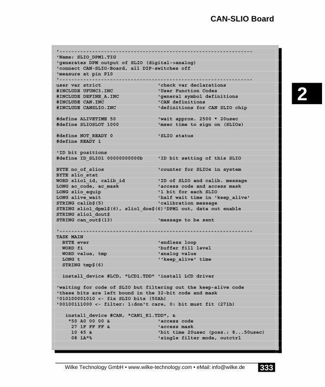
CAN-SLIO Board
Wilke Technology GmbH • www.wilke-technology.com • eMail: [email protected]
2
333
'-----------------------------------------------------------------'Name: SLIO_DPM1.TIG'generates DPM output of SLIO (digital->analog)'connect CAN-SLIO-Board, all DIP-switches off'measure at pin P10'-----------------------------------------------------------------user var strict 'check var declarations#INCLUDE UFUNC3.INC 'User Function Codes#INCLUDE DEFINE_A.INC 'general symbol definitions#INCLUDE CAN.INC 'CAN definitions#INCLUDE CANSLIO.INC 'definitions for CAN SLIO chip
#define ALIVETIME 50 'wait approx. 2500 * 20usec#define SLIOSLOT 1000 'msec time to sign on (SLIOs)
#define NOT_READY 0 'SLIO status#define READY 1
'ID bit positions#define ID_SLIO1 00000000000b 'ID bit setting of this SLIO
BYTE no_of_slios 'counter for SLIOs in systemBYTE slio_statWORD slio1_id, calib_id 'ID of SLIO and calib. messageLONG ac_code, ac_mask 'access code and access maskLONG slio_equip '1 bit for each SLIOLONG alive_wait 'half wait time in 'keep_alive'STRING calib$(5) 'calibration messageSTRING slio1_dpm1$(6), slio1_doe$(6)'DPM1 out, data out enableSTRING slio1_dout$STRING can_out$(13) 'message to be sent
'-----------------------------------------------------------------TASK MAIN BYTE ever 'endless loop WORD fi 'buffer fill level WORD value, tmp 'analog value LONG t ''keep_alive' time STRING tmp$(6)
install_device #LCD, "LCD1.TDD" 'install LCD driver
'waiting for code of SLIO but filtering out the keep-alive code'these bits are left bound in the 32-bit code and mask'010100001010 <- fix SLIO bits (50Ah)'00100111000 <- filter: 1:don't care, 0: bit must fit (271h)
install_device #CAN, "CAN1_K1.TDD", & "50 A0 00 00 & 'access code 27 1F FF FF & 'access mask 10 45 & 'bit time 20usec (poss.: 8...50usec) 08 1A"% 'single filter mode, outctrl

Device driver
Wilke Technology GmbH • www.wilke-technology.com • eMail: [email protected]
2
334
'ID of this SLIO: 0=standard frame '+ 2 ID bytes shifted by 5 slio1_id = (SLIO_FIX_ID bitor ID_SLIO1) shl 5 ' SLIO identifier calib_id = 0aah shl 5 'ID of calibration messages can_out$ = "" 'must be initialized
call find_slios 'generates a list of all SLIOs 'of the system if slio_equip = 0 then 'if found no SLIO goto no_slio_found 'then abort program else print #LCD, "<1Bh>A<0><2><0F0h>";no_of_slios;" SLIOs found"; endif wait_duration 1500 print #LCD, "<1>";
run_task show_slio 'shows what SLIO(s) send
slio1_doe$ = "<0><0><0><4><0FFh><0FFh>" 'SLIO_OUT_ENABLE slio1_doe$ = ntos$ ( slio1_doe$, 1, -2, slio1_id)'insert ID high byte1st can_out$ = slio1_doe$ wait_duration 1000
slio1_dout$ = "<0><0><0><3><0FFh><0FFh>" 'SLIO_DATA_OUT slio1_dout$ = ntos$ ( slio1_dout$, 1, -2, slio1_id )'zuerst insert IDhigh byte 1st can_out$ = slio1_dout$ wait_duration 1000 slio1_dout$ = "<0><0><0><3><0><0>" slio1_dout$ = ntos$ ( slio1_dout$, 1, -2, slio1_id )'insert ID can_out$ = slio1_dout$ wait_duration 1000
slio1_dpm1$ = "<0><0><0><6><0><0>" 'SLIO_DPM1 slio1_dpm1$ = ntos$ ( slio1_dpm1$, 1, -2, slio1_id )'first insert IDhigh byte 1st value = 0 t = ticks() stop_task keep_alive 'main loop will do this now for ever = 0 to 0 step 0 'endless loop ---------- tmp = value shl 5 '10 bit right bound in WORD tmp$ = ntos$ ( slio1_dpm1$, 4, -2, tmp )'insert value high byte 1st can_out$ = tmp$ put #CAN, tmp$ value = modulo_inc ( value, 0, 7FFh, 7Fh ) 'inc step 7Fh if diff_ticks ( t ) > 50 then 'value depends on bit time put #CAN, calib$ 'send calibration message t = ticks() endif next 'endless loop ----------
no_slio_found: 'no SLIO found stop_task keep_alive print #LCD, "<1>no SLIO found"

CAN-SLIO Board
Wilke Technology GmbH • www.wilke-technology.com • eMail: [email protected]
2
335
print #LCD, "program terminated"END
'-----------------------------------------------------------------'Displays content of SLIO messages'Line 1 on LCD: ID'Line 2 on LCD: data bytes in HEX'-----------------------------------------------------------------TASK show_slio BYTE ever, i 'loop variables WORD ibu_fill 'input buffer fill length BYTE frameformat, msg_len 'frame format and length ofmessage LONG r_id STRING msg$(13), data$(8) 'message and data
for ever = 0 to 0 step 0 'endless looprx_cont: get #CAN, #0, #UFCI_IBU_FILL, 0, ibu_fill if ibu_fill > 2 then 'if at least one message get #CAN, #0, 1, frameformat 'get frame info byte msg_len = frameformat bitand 1111b 'length if frameformat bitand 80h = 0 then 'if standard frame get #CAN, #0, CAN_ID11_LEN, r_id 'get ID bytes r_id = byte_mirr ( r_id, 2 ) r_id = r_id shr 5 'if no SLIO message if r_id bitand SLIO_ID_IMASK <> SLIO_FIX_ID then 'free buffer if msg_len > 0 then 'if contains data: throw away get #CAN, #0, msg_len, data$'get them and free the buffer endif goto rx_cont 'wait for next message endif else 'else it is extended frame get #CAN, #0, CAN_ID29_LEN, r_id'and no SLIO message if msg_len > 0 then 'if contains data get #CAN, #0, msg_len, data$ 'get them and free the buffer endif goto rx_cont 'wait for next message endif '---------------------------- 'here: it was a SLIO message using "UH<3><3> 0 0 0 0 3" 'to display ID print_using #LCD, "<1Bh>A<0><1><0F0h> ID:";r_id 'ID of SLIO print #LCD, " <13>DATA:";'clear data line if msg_len > 0 then 'if contains data get #CAN, #0, msg_len, data$ 'get them and display using "UH<2><2> 0.0.0.0.2" 'format for HEX output for i = 0 to len ( data$ ) - 1 'all bytes of the string print_using #LCD, asc ( mid$ ( data$, i, 1 ) );'in HEX next endif endif nextEND

Device driver
Wilke Technology GmbH • www.wilke-technology.com • eMail: [email protected]
2
336
'-----------------------------------------------------------------'Sends calibration messages and waits for'(filtered) SLIO messages as response'Within a certain time slot all SLIOs must have sent their'sign_on messages. Filter should be set by main program.'Non-SLIO messages or extended frames are just removed'from the buffer.'-----------------------------------------------------------------SUB find_slios () BYTE ever, i 'loop variables WORD ibu_fill 'input buffer fill length BYTE frameformat, msg_len 'frame format and length of message LONG r_id LONG t STRING msg$(13), data$(8) 'message and data
slio_equip = 0 'begin with 'no SLIO' no_of_slios = 0 calib_id = 0aah shl 5 'ID of calibration messages calib$ = "<0><0><0><0aah><4>" 'special string to init the SLIO calib$ = ntos$ ( calib$, 1, -2, calib_id )'insert ID high byte 1st
alive_wait = ALIVETIME/2 'in init phase shorter run_task keep_alive 'sends calibration messages 'and keeps SLIOs synchronized print #LCD, "trying to find SLIOs"; t = ticks() 'begin of time slot while diff_ticks ( t ) < SLIOSLOT 'within the time slotfind_cont: wait_duration 50 get #CAN, #0, #UFCI_IBU_FILL, 0, ibu_fill if ibu_fill > 2 then 'if at least one message get #CAN, #0, 1, frameformat 'get frame info byte msg_len = frameformat bitand 1111b 'length if frameformat bitand 80h = 0 then 'if standard frame get #CAN, #0, CAN_ID11_LEN, r_id 'get ID bytes r_id = byte_mirr ( r_id, 2 ) r_id = r_id shr 5 'if no SLIO message if r_id bitand SLIO_ID_IMASK <> SLIO_FIX_ID then 'free buffer if msg_len > 0 then 'if contains data: throw away get #CAN, #0, msg_len, data$'get them and free the buffer endif goto find_cont 'wait for next message endif else 'else it is extended frame get #CAN, #0, CAN_ID29_LEN, r_id'and no SLIO message if msg_len > 0 then 'if contains data get #CAN, #0, msg_len, data$ 'get them and free the buffer endif goto find_cont 'wait for next message endif'-----------------------------------------------------------------

CAN-SLIO Board
Wilke Technology GmbH • www.wilke-technology.com • eMail: [email protected]
2
337
'here: it was a SLIO message. Find out its address'and enter into bit list. Use this address in test program.
slio1_id = ( r_id bitand 7FEh) shl 5 'take this address for test 'mask out DIR bit r_id = r_id bitand SLIO_ID_MASK 'settable SLIO address bits if bit ( r_id, 8 ) = 1 then 'if P8 set then r_id = ( r_id bitand 111000b ) + 40h 'generate 4-bit addr endif r_id = r_id shr 3 'shift away lower 3 ID bits set_bit slio_equip, r_id 'set bit number in list print #LCD, "<1Bh>A<0><1><0F0h>SLIO ";r_id;" found" no_of_slios = no_of_slios + 1 'count the found SLIO 'ignore here info in data bytes if msg_len > 0 then 'if contains data get #CAN, #0, msg_len, data$ 'get them out of the buffer'' using "UH<2><2> 0.0.0.0.2" ' format for HEX output'' for i = 0 to len ( data$ ) - 1 all bytes of the string'' print_using #LCD, asc ( mid$ ( data$, i, 1 ) );' in HEX'' next endif endif endwhile alive_wait = ALIVETIME 'normal wait time 'keep_alive'END
'-----------------------------------------------------------------'Sends calibration messages in order to keep the SLIO synchronized.'After max. 8000 bit times a calibration message must be sent.
'-----------------------------------------------------------------TASK keep_alive BYTE ever LONG t
t = ticks() for ever = 0 to 0 step 0 'endless loop if diff_ticks ( t ) > 50 then 'value depends on bit time put #CAN, calib$ 'send calibration message t = ticks() endif if can_out$ <> "" then put #CAN, can_out$ 'send message can_out$ = "" 'empty = sent endif nextEND

Device driver
Wilke Technology GmbH • www.wilke-technology.com • eMail: [email protected]
2
338
Analog configurationThe SLIO chip provides quite a complex structure to record analog input signals. Aresolution of 7..8 bit is achieved. The conversion rate is just as high as the output rateat the quasi-analog output. A conversion needs 1024 bit times.
The A/D converter in the upper part of the illustration uses the pin P15 as an analoginput and P16 as feedback output. The input assignment consists of R1 and R2 (each100 k) and C1 (3.3 nF). This type of input is available on the CAN-SLIO board at thepin Ai15. The pin P15 must remain open if Ai15 is used.
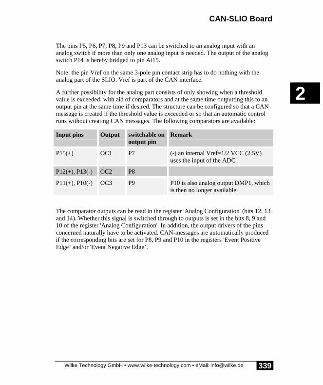
CAN-SLIO Board
Wilke Technology GmbH • www.wilke-technology.com • eMail: [email protected]
2
339
The pins P5, P6, P7, P8, P9 and P13 can be switched to an analog input with ananalog switch if more than only one analog input is needed. The output of the analogswitch P14 is hereby bridged to pin Ai15.
Note: the pin Vref on the same 3-pole pin contact strip has to do nothing with theanalog part of the SLIO. Vref is part of the CAN interface.
A further possibility for the analog part consists of only showing when a thresholdvalue is exceeded with aid of comparators and at the same time outputting this to anoutput pin at the same time if desired. The structure can be configured so that a CANmessage is created if the threshold value is exceeded or so that an automatic controlruns without creating CAN messages. The following comparators are available:
Input pins Output switchable onoutput pin
Remark
P15(+) OC1 P7 (-) an internal Vref=1/2 VCC (2.5V)uses the input of the ADC
P12(+), P13(-) OC2 P8
P11(+), P10(-) OC3 P9 P10 is also analog output DMP1, whichis then no longer available.
The comparator outputs can be read in the register 'Analog Configuration' (bits 12, 13and 14). Whether this signal is switched through to outputs is set in the bits 8, 9 and10 of the register 'Analog Configuration'. In addition, the output drivers of the pinsconcerned naturally have to be activated. CAN-messages are automatically producedif the corresponding bits are set for P8, P9 and P10 in the registers 'Event PositiveEdge’ and/or 'Event Negative Edge’.

Device driver
Wilke Technology GmbH • www.wilke-technology.com • eMail: [email protected]
2
340
The 'Analog Configuration' register (address 5):
ADC OC3 OC2 OC1 0 M3 M2 M1 S3 S2 S1 0 0 0 0 0
Bit(s) Function
0...4 no function
S3 S2 S1 position of analog switch
0 0 0 no switch closed
0 0 1 P7 at P14
0 1 0 P6 at P14
0 1 1 P5 at P14
1 0 0 P8 at P14
1 0 1 P9 at P14
1 1 0 P13 at P14
1 1 1 reserved
position of monitoring switch
M1 1: OC1 at P7
M2 1: OC3 at P9
M3 1: OC2 at P8
11 no function
result of analog comparators
OC1 1: P15 > Vref-internal (2.5V)
OC2 1: P13 > P12
OC3 1: P11 > P10
ADC 1: starts A/D conversion
CAN-SLIO Board
Wilke Technology GmbH • www.wilke-technology.com • eMail: [email protected]
2
341
There are some rules (in every case the danger of a short-circuit):
• if the analog switch is set, P14 may not be an output if.• if M1 is set, i.e. OC1 is switched to P7, P7 may not be an output.• if M2 is set, i.e. OC3 is switched to P9, P9 may not be an output.• if M3 is set, i.e. OC2 is switched to P8, P8 may not be an output.
Starting the A/D conversionA conversion needs 1024 bit times and delivers an accuracy of 7...8 bits.
The A/D converter is started, if
• the register 'A/D-Conversion' is described. The answer is carried outautomatically after conversion.
• the register 'Analog Configuration' is described with set bit 'ADC'. Theanswer is carried out automatically after conversion.
The example program reads analog measured values on the pin P15. The subroutine'find_slios' together with the task 'keep_alive' finds the SLIO(s) as describedunder 'find SLIOs on the bus'. The task 'show_slio' shows the incoming SLIOmessages and the Identifier on the LCD in HEX as a control. Foreign messages,which automatically include extended frames, are rejected by 'show_slio', only thereceive buffer is cleared.
Debugging: if you examine the SLIO example program in the debug mode by singlesteps the SLIO will probably enter the Sleep-Mode, since the calibration messages aremissing for too long. Single steps should best be executed specifically after aBreakpoint. After this you must reboot so that the SLIO is found anew.
Program example:
'-----------------------------------------------------------------'Name: SLIO_ANA1.TIG'Reads the analog input of the SLIO at P15, and displays'the value in HEX (0...7FFh)'Connect CAN-SLIO-Board'-----------------------------------------------------------------user var strict 'check var declarations#INCLUDE UFUNC3.INC 'User Function Codes#INCLUDE DEFINE_A.INC 'general symbol definitions#INCLUDE CAN.INC 'CAN definitions#INCLUDE CANSLIO.INC 'definitions for CAN SLIO chip
#define ALIVETIME 50 'wait approx. 2500 * 20usec

Device driver
Wilke Technology GmbH • www.wilke-technology.com • eMail: [email protected]
2
342
#define SLIOSLOT 1000 'msec time to sign on (SLIOs)#define NOT_READY 0 'SLIO status#define READY 1
'ID bit positions#define ID_SLIO1 00000000000b 'ID bit setting of this SLIO
'gloabal variablesBYTE no_of_slios 'counter for SLIOs in systemBYTE slio_statWORD slio1_id, calib_id 'ID of SLIO and calib. messageLONG ac_code, ac_mask 'access code and access maskLONG slio_equip '1 bit for each SLIOLONG alive_wait 'half wait time in 'keep_alive'WORD acfg 'analog configuration bitsSTRING calib$(5) 'calibration messageSTRING slio1_doe$(6) 'data out enableSTRING slio1_acfg$(6), slio1_ain$(6)'analog config, analog inSTRING can_out$(13k) ' message to be sent to SLIO
'-----------------------------------------------------------------TASK MAIN BYTE ever 'endless loop WORD fi 'buffer fill level STRING tmp$(6)
install_device #LCD, "LCD1.TDD"
'waiting for code of SLIO but filtering out the keep-alive code'these bits are left bound in the 32-bit code and mask'010100001010 <- fix SLIO bits (50Ah)'00100111000 <- filter: 1:don't care, 0: bit must fit (271h)
install_device #CAN, "CAN1_K1.TDD", & "50 A0 00 00 & 'access code 27 1F FF FF & 'access mask 10 45 & 'bit time 20usec (poss.: 8...50usec) 08 1A"% 'single filter mode, outctrl
'ID of this SLIO: 0=standard frame '+ 2 ID bytes shifted by 5 slio1_id = (SLIO_FIX_ID bitor ID_SLIO1) shl 5 ' SLIO identifier calib_id = 0aah shl 5 'ID of calibration messages can_out$ = "" 'must be initialized
call find_slios 'generates a list of all SLIOs 'of the system if slio_equip = 0 then 'if found no SLIO goto no_slio_found 'then abort program else print #LCD, "<1Bh>A<0><2><0F0h>";no_of_slios;" SLIOs found"; endif wait_duration 1500 print #LCD, "<1>";

CAN-SLIO Board
Wilke Technology GmbH • www.wilke-technology.com • eMail: [email protected]
2
343
run_task show_slio 'shows what SLIO(s) send
slio1_doe$ = "<0><0><0><4><0><0>" 'SLIO_OUT_ENABLE all inputs slio1_doe$ = ntos$ ( slio1_doe$, 1, -2, slio1_id)'insert ID high byte1st can_out$ = slio1_doe$ 'have it output wait_duration 100 'prepare the analog config message slio1_acfg$ = "<0><0><0><5><0><0>" 'SLIO_OUT_ENABLE all inputs slio1_acfg$ = ntos$ ( slio1_acfg$, 1, -2, slio1_id)'insert ID high byte1st' aooo-mmmsss----- acfg = 1000000000000000b 'only 'start conversion bit' set 'ooo = 0, mmm = 0: nothing monitored 'sss = 0, no analog switch for ever = 0 to 0 step 0 'endless loop ---------- tmp$ = ntos$ ( slio1_acfg$, 4, -2, acfg)'insert config word can_out$ = tmp$ 'have it output, starts A/D wait_duration 1000 next 'endless loop ----------
no_slio_found: 'no SLIO found stop_task keep_alive print #LCD, "<1>no SLIO found" print #LCD, "program terminated"END
'-----------------------------------------------------------------'Displays content of SLIO messages'Line 1 on LCD: ID'Line 2 on LCD: data bytes in HEX'-----------------------------------------------------------------TASK show_slio BYTE ever, i 'loop variables BYTE frameformat, msg_len 'frame format and length of message WORD ibu_fill 'input buffer fill length WORD value 'analog value LONG r_id 'receive ID STRING msg$(13), data$(8) 'message and data
for ever = 0 to 0 step 0 'endless looprx_cont: get #CAN, #0, #UFCI_IBU_FILL, 0, ibu_fill if ibu_fill > 2 then 'if at least one message get #CAN, #0, 1, frameformat 'get frame info byte msg_len = frameformat bitand 1111b 'length if frameformat bitand 80h = 0 then 'if standard frame get #CAN, #0, CAN_ID11_LEN, r_id 'get ID bytes r_id = byte_mirr ( r_id, 2 ) r_id = r_id shr 5 'if no SLIO message if r_id bitand SLIO_ID_IMASK <> SLIO_FIX_ID then 'free buffer if msg_len > 0 then 'if contains data: throw away

Device driver
Wilke Technology GmbH • www.wilke-technology.com • eMail: [email protected]
2
344
get #CAN, #0, msg_len, data$'get them and free the buffer endif goto rx_cont 'wait for next message endif else 'else it is extended frame get #CAN, #0, CAN_ID29_LEN, r_id'and no SLIO message if msg_len > 0 then 'if contains data get #CAN, #0, msg_len, data$ 'get them and free the buffer endif goto rx_cont 'wait for next message endif '---------------------------- 'here: it was a SLIO message using "UH<3><3> 0 0 0 0 3" 'to display ID print_using #LCD, "<1Bh>A<0><1><0F0h> ID:";r_id 'ID of SLIO if msg_len = 3 then 'if contains data get #CAN, #0, msg_len, data$ 'get them and display if nfroms ( data$, 0, 1 ) = 8 then 'og register value = nfroms ( data$, 1, 2 ) value = byte_mirr ( value, 2 ) shr 5 using "UH<3><3> 0.0.0.0.3" ' format for HEX output print_using #LCD, " P15:";value; endif endif ' msg_len endif ' ibu_fill nextEND
'-----------------------------------------------------------------'Sends calibration messages and waits for'(filtered) SLIO messages as response'Within a certain time slot all SLIOs must have sent their'sign_on messages. Filter should be set by main program.'Non-SLIO messages or extended frames are just removed'from the buffer.'-----------------------------------------------------------------SUB find_slios () BYTE ever, i 'loop variables WORD ibu_fill 'input buffer fill length BYTE frameformat, msg_len 'frame format and length of message LONG r_id LONG t STRING msg$(13), data$(8) 'message and data
slio_equip = 0 'begin with 'no SLIO' no_of_slios = 0 calib_id = 0aah shl 5 'ID of calibration messages calib$ = "<0><0><0><0aah><4>" 'special string to init the SLIO calib$ = ntos$ ( calib$, 1, -2, calib_id )'insert ID high byte 1st
alive_wait = ALIVETIME/2 'in init phase shorter run_task keep_alive 'sends calibration messages 'and keeps SLIOs synchronized print #LCD, "trying to find SLIOs"; t = ticks() 'begin of time slot
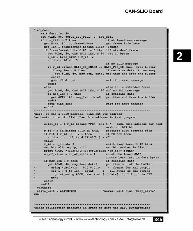
CAN-SLIO Board
Wilke Technology GmbH • www.wilke-technology.com • eMail: [email protected]
2
345
while diff_ticks ( t ) < SLIOSLOT 'within the time slotfind_cont: wait_duration 50 get #CAN, #0, #UFCI_IBU_FILL, 0, ibu_fill if ibu_fill > 2 then 'if at least one message get #CAN, #0, 1, frameformat 'get frame info byte msg_len = frameformat bitand 1111b 'length if frameformat bitand 80h = 0 then 'if standard frame get #CAN, #0, CAN_ID11_LEN, r_id 'get ID bytes r_id = byte_mirr ( r_id, 2 ) r_id = r_id shr 5 'if no SLIO message if r_id bitand SLIO_ID_IMASK <> SLIO_FIX_ID then 'free buffer if msg_len > 0 then 'if contains data: throw away get #CAN, #0, msg_len, data$'get them and free the buffer endif goto find_cont 'wait for next message endif else 'else it is extended frame get #CAN, #0, CAN_ID29_LEN, r_id'and no SLIO message if msg_len > 0 then 'if contains data get #CAN, #0, msg_len, data$ 'get them and free the buffer endif goto find_cont 'wait for next message endif'-----------------------------------------------------------------'here: it was a SLIO message. Find out its address'and enter into bit list. Use this address in test program.
slio1_id = ( r_id bitand 7FEh) shl 5 ' take this address for test 'mask out DIR bit r_id = r_id bitand SLIO_ID_MASK 'settable SLIO address bits if bit ( r_id, 8 ) = 1 then 'if P8 set then r_id = ( r_id bitand 111000b ) + 40h endif r_id = r_id shr 3 'shift away lower 3 ID bits set_bit slio_equip, r_id 'set bit number in list print #LCD, "<1Bh>A<0><1><0F0h>SLIO ";r_id;" found" no_of_slios = no_of_slios + 1 'count the found SLIO 'ignore here info in data bytes if msg_len > 0 then 'if contains data get #CAN, #0, msg_len, data$ 'get them out of the buffer'' using "UH<2><2> 0.0.0.0.2" ' format for HEX output'' for i = 0 to len ( data$ ) - 1 all bytes of the string'' print_using #LCD, asc ( mid$ ( data$, i, 1 ) );' in HEX'' next endif endif endwhile alive_wait = ALIVETIME 'normal wait time 'keep_alive'END
'-----------------------------------------------------------------'Sends calibration messages in order to keep the SLIO synchronized.

Device driver
Wilke Technology GmbH • www.wilke-technology.com • eMail: [email protected]
2
346
'After max. 8000 bit times a calibration message must be sent.'-----------------------------------------------------------------TASK keep_alive BYTE ever
for ever = 0 to 0 step 0 'endless loop put #CAN, calib$ 'send calibration message wait_duration alive_wait 'wait max 8000 bit times if can_out$ <> "" then put #CAN, can_out$ 'send message can_out$ = "" 'empty = sent endif wait_duration alive_wait 'wait max 8000 bit times nextEND

CAN-SLIO Board
Wilke Technology GmbH • www.wilke-technology.com • eMail: [email protected]
2
347
Two SLIOs on one busThe following example is a combination of SLIO_DPM1.TIG andSLIO_HIGH_LOW.TIG. It produces DPM outputs on SLIO1 (digital->analog) anddigital rectangular outputs on SLIO2. Set all DIP-switches on one CAN-SLIO boardto OFF and only DIP-switch ID3 to ON on the other CAN-SLIO board.
Program example:
'-----------------------------------------------------------------'Name: SLIO_2.TIG'2 SLIOs in the system'generates DPM output on SLIO1 (digital->analog)'generates digital output on SLIO2 (sqaure wave)'connect'1 CAN-SLIO-Board, all DIP-switches off'1 CAN-SLIO-Board, only DIP-switch ID3 on'measure at pin P10'-----------------------------------------------------------------user var strict 'check var declarations#INCLUDE UFUNC3.INC 'User Function Codes#INCLUDE DEFINE_A.INC 'general symbol definitions#INCLUDE CAN.INC 'CAN definitions#INCLUDE CANSLIO.INC 'definitions for CAN SLIO chip
#define ALIVETIME 50 'wait approx. 2500 * 20usec#define SLIOSLOT 1000 'msec time to sign on (SLIOs)
#define NOT_READY 0 'SLIO status#define READY 1
'ID bit positions#define ID_SLIO1 00000000000b 'ID bit setting of SLIO2#define ID_SLIO2 00000001000b 'ID bit setting of SLIO2
BYTE no_of_slios 'counter for SLIOs in systemBYTE slio_12_found 'flag showing SLIOs 1 and 2 foundBYTE slio_statWORD slio1_id, slio2_id, calib_id 'ID of SLIOs and calib. messageLONG ac_code, ac_mask 'access code and access maskLONG slio_equip '1 bit for each SLIOLONG alive_wait 'half wait time in 'keep_alive'STRING calib$(5) 'calibration messageSTRING slio1_dpm1$(6), slio1_doe$(6)'DPM1 out, data out enableSTRING slio2_doe$(6) 'data out enable SLIO2STRING slio1_dout$STRING slio2_dout$STRING can_out$(13) 'message to be sent
'-----------------------------------------------------------------TASK MAIN

Device driver
Wilke Technology GmbH • www.wilke-technology.com • eMail: [email protected]
2
348
BYTE ever 'endless loop WORD fi 'buffer fill level WORD value, tmp 'analog value LONG t ''keep_alive' time LONG digi 'for digital output STRING tmp$(6)
install_device #LCD, "LCD1.TDD" 'install LCD driver
'waiting for code of SLIO but filtering out the keep-alive code'these bits are left bound in the 32-bit code and mask'010100001010 <- fix SLIO bits (50Ah)'00100111000 <- filter: 1:don't care, 0: bit must fit (271h)
install_device #CAN, "CAN1_K1.TDD", & "50 A0 00 00 & 'access code 27 1F FF FF & 'access mask 10 45 & 'bit time 20usec (poss.: 8...50usec) 08 1A"% 'single filter mode, outctrl
'ID of this SLIO: 0=standard frame '+ 2 ID bytes shifted by 5 calib_id = 0aah shl 5 'ID of calibration messages can_out$ = "" 'must be initialized
call find_slios 'generates a list of all SLIOs 'of the system if slio_equip = 0 then 'if found no SLIO goto no_slio_found 'then abort program else print #LCD, "<1Bh>A<0><2><0F0h>";no_of_slios;" SLIOs found"; endif if slio_equip bitand 000000011b <> 3 then 'if found not found SLIO1/2 print #LCD, "<1Bh>A<0><3><0F0h>SLIO1/2 not found"; endif wait_duration 1500 print #LCD, "<1>";
slio1_id = (SLIO_FIX_ID bitor ID_SLIO1) shl 5 'SLIO1 identifier slio2_id = (SLIO_FIX_ID bitor ID_SLIO2) shl 5 'SLIO2 identifier run_task show_slio 'shows what SLIO(s) send
slio1_doe$ = "<0><0><0><4><0FFh><0FFh>" 'SLIO1_OUT_ENABLE slio1_doe$ = ntos$ ( slio1_doe$, 1, -2, slio1_id)'insert ID high byte1st can_out$ = slio1_doe$ wait_duration 1000
slio1_dout$ = "<0><0><0><3><0FFh><0FFh>" 'SLIO1_DATA_OUT slio1_dout$ = ntos$ ( slio1_dout$, 1, -2, slio1_id )'zuerst insert IDhigh byte 1st can_out$ = slio1_dout$ wait_duration 1000 slio1_dout$ = "<0><0><0><3><0><0>" 'SLIO1_DATA_OUT slio1_dout$ = ntos$ ( slio1_dout$, 1, -2, slio1_id )'insert ID

CAN-SLIO Board
Wilke Technology GmbH • www.wilke-technology.com • eMail: [email protected]
2
349
can_out$ = slio1_dout$ wait_duration 1000
slio2_doe$ = "<0><0><0><4><0FFh><0FFh>" 'SLIO2_OUT_ENABLE slio2_doe$ = ntos$ ( slio2_doe$, 1, -2, slio2_id)'insert ID high byte1st can_out$ = slio2_doe$ slio2_dout$ = "<0><0><0><3><0FFh><0FFh>" 'SLIO1_DATA_OUT slio2_dout$ = ntos$ ( slio2_dout$, 1, -2, slio2_id )'insert ID wait_duration 1000
slio1_dpm1$ = "<0><0><0><6><0><0>" 'SLIO1_DPM1 slio1_dpm1$ = ntos$ ( slio1_dpm1$, 1, -2, slio1_id )'zuerst insert IDhigh byte 1st value = 0 digi = 0 'digital output value t = ticks() stop_task keep_alive 'main loop will do this now for ever = 0 to 0 step 0 'endless loop ---------- tmp = value shl 5 '10 bit right bound in WORD tmp$ = ntos$ ( slio1_dpm1$, 4, -2, tmp )'insert value high byte 1st put #CAN, tmp$ tmp$ = ntos$ ( slio2_dout$, 4, -2, digi )'insert value high byte 1st put #CAN, tmp$ digi = digi + 1 'change dig. output value value = modulo_inc ( value, 0, 7FFh, 7Fh ) 'inc step 7Fh if diff_ticks ( t ) > 50 then 'value depends on bit time put #CAN, calib$ 'send calibration message t = ticks() endif next 'endless loop ----------
no_slio_found: 'no SLIO found stop_task keep_alive print #LCD, "<1>no SLIO found" print #LCD, "program terminated"END
'-----------------------------------------------------------------'Displays content of SLIO messages'Line 1 on LCD: ID'Line 2 on LCD: data bytes in HEX'-----------------------------------------------------------------TASK show_slio BYTE ever, i 'loop variables WORD ibu_fill 'input buffer fill length BYTE frameformat, msg_len 'frame format and length ofmessage LONG r_id STRING msg$(13), data$(8) 'message and data
for ever = 0 to 0 step 0 'endless looprx_cont: get #CAN, #0, #UFCI_IBU_FILL, 0, ibu_fill

Device driver
Wilke Technology GmbH • www.wilke-technology.com • eMail: [email protected]
2
350
if ibu_fill > 2 then 'if at least one message get #CAN, #0, 1, frameformat 'get frame info byte msg_len = frameformat bitand 1111b 'length if frameformat bitand 80h = 0 then 'if standard frame get #CAN, #0, CAN_ID11_LEN, r_id 'get ID bytes r_id = byte_mirr ( r_id, 2 ) r_id = r_id shr 5 'if no SLIO message if r_id bitand SLIO_ID_IMASK <> SLIO_FIX_ID then 'free buffer if msg_len > 0 then 'if contains data: throw away get #CAN, #0, msg_len, data$'get them and free the buffer endif goto rx_cont 'wait for next message endif else 'else it is extended frame get #CAN, #0, CAN_ID29_LEN, r_id'and no SLIO message if msg_len > 0 then 'if contains data get #CAN, #0, msg_len, data$ 'get them and free the buffer endif goto rx_cont 'wait for next message endif '---------------------------- 'here: it was a SLIO message using "UH<3><3> 0 0 0 0 3" 'to display ID print_using #LCD, "<1Bh>A<0><1><0F0h> ID:";r_id 'ID of SLIO print #LCD, " <13>DATA:";'clear data line if msg_len > 0 then 'if contains data get #CAN, #0, msg_len, data$ 'get them and display using "UH<2><2> 0.0.0.0.2" 'format for HEX output for i = 0 to len ( data$ ) - 1 'all bytes of the string print_using #LCD, asc ( mid$ ( data$, i, 1 ) );'in HEX next endif endif nextEND
'-----------------------------------------------------------------'Sends calibration messages and waits for'(filtered) SLIO messages as response'Within a certain time slot all SLIOs must have sent their'sign_on messages. Filter should be set by main program.'Non-SLIO messages or extended frames are just removed'from the buffer.'-----------------------------------------------------------------SUB find_slios () BYTE ever, i 'loop variables WORD ibu_fill 'input buffer fill length BYTE frameformat, msg_len 'frame format and length of message LONG r_id LONG t STRING msg$(13), data$(8) 'message and data
slio_equip = 0 'begin with 'no SLIO' no_of_slios = 0

CAN-SLIO Board
Wilke Technology GmbH • www.wilke-technology.com • eMail: [email protected]
2
351
calib_id = 0aah shl 5 'ID of calibration messages calib$ = "<0><0><0><0aah><4>" 'special string to init the SLIO calib$ = ntos$ ( calib$, 1, -2, calib_id )'insert ID high byte 1st
alive_wait = ALIVETIME/2 'in init phase shorter run_task keep_alive 'sends calibration messages 'and keeps SLIOs synchronized print #LCD, "trying to find SLIOs"; t = ticks() 'begin of time slot while diff_ticks ( t ) < SLIOSLOT 'within the time slotfind_cont: wait_duration 50 get #CAN, #0, #UFCI_IBU_FILL, 0, ibu_fill if ibu_fill > 2 then 'if at least one message get #CAN, #0, 1, frameformat'get frame info byte msg_len = frameformat bitand 1111b 'length if frameformat bitand 80h = 0 then 'if standard frame get #CAN, #0, CAN_ID11_LEN, r_id 'get ID bytes r_id = byte_mirr ( r_id, 2 ) r_id = r_id shr 5 'if no SLIO message if r_id bitand SLIO_ID_IMASK <> SLIO_FIX_ID then 'free buffer if msg_len > 0 then 'if contains data: throw away get #CAN, #0, msg_len, data$'get them and free the buffer endif goto find_cont 'wait for next message endif else 'else it is extended frame get #CAN, #0, CAN_ID29_LEN, r_id'and no SLIO message if msg_len > 0 then 'if contains data get #CAN, #0, msg_len, data$ 'get them and free the buffer endif goto find_cont 'wait for next message endif'-----------------------------------------------------------------'here: it was a SLIO message. Find out its address'and enter into bit list. Use this address in test program.
slio1_id = ( r_id bitand 7FEh) shl 5 'take this address for test 'mask out DIR bit r_id = r_id bitand SLIO_ID_MASK 'settable SLIO address bits if bit ( r_id, 8 ) = 1 then 'if P8 set then r_id = ( r_id bitand 111000b ) + 40h 'generate 4-bit addr endif r_id = r_id shr 3 'shift away lower 3 ID bits set_bit slio_equip, r_id 'set bit number in list
using "UH<1><1> 0 0 0 0 1" 'to display slio_equip print_using #LCD, "<1Bh>A<0><1><0F0h>SLIO_equip ";slio_equip no_of_slios = no_of_slios + 1 'count the found SLIO 'ignore here info in data bytes if msg_len > 0 then 'if contains data get #CAN, #0, msg_len, data$ 'get them out of the buffer'' using "UH<2><2> 0.0.0.0.2" ' format for HEX output'' for i = 0 to len ( data$ ) - 1 all bytes of the string

Device driver
Wilke Technology GmbH • www.wilke-technology.com • eMail: [email protected]
2
352
'' print_using #LCD, asc ( mid$ ( data$, i, 1 ) );' in HEX'' next endif endif endwhile alive_wait = ALIVETIME 'normal wait time 'keep_alive'END
'-----------------------------------------------------------------'Sends calibration messages in order to keep the SLIO synchronized.'After max. 8000 bit times a calibration message must be sent.
'-----------------------------------------------------------------TASK keep_alive BYTE ever LONG t
t = ticks() for ever = 0 to 0 step 0 'endless loop if diff_ticks ( t ) > 50 then 'value depends on bit time put #CAN, calib$ 'send calibration message t = ticks() endif if can_out$ <> "" then put #CAN, can_out$ 'send message can_out$ = "" 'empty = sent endif nextEND

Touch-Memory
Wilke Technology GmbH • www.wilke-technology.com • eMail: [email protected]
2
353
Touch-MemoryThe device driver ‘TMEM.TDD’ supports the serial connection with Touch-Memorymodules in series DS199x from Dallas Semiconductor. During installation of thedriver the file name specifies at which pin the Touch-Memory is connected. Thetransmission timing is determined by the TIMERA setting.
File name: TMEM_Pp.TDD
INSTALL DEVICE #D, "TMEM_Pp.TDD", ResTim, PresTim, NCTim
D is a constant, variable or expression of the data type BYTE,WORD, LONG in the range from 0...63 and stands for thedevice number of the driver.
Ppp in the file name stands for:P: internal portp: measuring pin.
ResTim is a parameter to determine the remaining time in TIMERA-Ticks.
PresTim is a parameter to determine the time for 'Wait For Presence' inTIMERA-Ticks.
NCTim is a parameter to determine the time in TIMERA-Ticks, whichhas to be waited after a 'Presence'-Signal until communication(No-Communication-Time).
A byte is always read or written at the speed of the TIMERA-Ticks. The timing for'Reset', 'Wait for Presence' and 'No Communication after Presence' can be varied withthe installation parameters.
Use the instruction PUT to write up to 256 bytes in the Touch-Memory:
PUT #D, String$
D is a constant, variable or expression of the data type BYTE,WORD, LONG in the range from 0...63 and stands for thedevice number of the driver.
String$ contains the bytes to be written in the Touch-Memory. The datais initially transferred to the output buffer and then sent fromthe device driver to the external chip.
Device driver
Wilke Technology GmbH • www.wilke-technology.com • eMail: [email protected]
2
354
To read data from a Touch-Memory, the desired number of bytes to be read is outputat secondary channel 1 with the instruction PUT:
PUT #D, #1, Number
D is a constant, variable or expression of the data type BYTE,WORD, LONG in the range from 0...63 and stands for thedevice number of the driver.
Number specifies how many bytes are to be read from the Touch-Memory. The data is initially transferred to the input buffer andthen read from the device driver with the instruction GET.
Once the read command has been sent the buffer level can be queried to determinewhether the desired number of characters can be read:
The Touch-Memory is reset by outputting a random value at secondary address 2. The'Presence' signal is checked at the same time:
PUT #D, #2, Dummy
Both incoming and sent data are held in a buffer. Size, level or remaining space in theinput and output buffer, status information as well as the driver version can be queriedwith User-Function-Codes.
Touch-Memory
Wilke Technology GmbH • www.wilke-technology.com • eMail: [email protected]
2
355
User-Function-Codes for inquiry (instruction GET):
No SymbolPrefix UFCI_
Description
1 UFCI_IBU_FILL Level of input buffer (Byte)
2 UFCI_IBU_FREE Free space in input buffer (Byte)
3 UFCI_IBU_VOL Size of input buffer (Byte)
33 UFCI_OBU_FILL Level of output buffer (Byte)
34 UFCI_OBU_FREE Free space in output buffer (Byte)
35 UFCI_OBU_VOL Size of output buffer (Byte)
65 UFCI_LAST_ERRC Last Error-Code
99 UFCI_DEV_VERS Device version
160 UFCI_TMEM_OVL Overflow-Status:0: okn: number of buffer overflows
161 UFCI_TMEM_PRS Presence-Status:0: ok<>0: not present
User-Function-Codes of I/O-buffer for the instruction PUT:
No Symbol Description
1 UFCO_IBU_ERASE Delete input buffer
33 UFCO_OBU_ERASE Delete output buffer
The Touch-Memory is connected to the Portpin with one line. The line has a Pull-up-resistor of 4k7 against VCC.

Device driver
Wilke Technology GmbH • www.wilke-technology.com • eMail: [email protected]
2
356
Program example:
'--------------------------------------------------------------------'Name: TMEM1.TIG'DS1993'--------------------------------------------------------------------user_var_strict#include DEFINE_A.INC 'general definitions#include UFUNC3.INC 'user function codes
TASK MAIN BYTE TMEM_PRES 'TMEM presence flag BYTE FAM_CODE 'family code of the chip LONG SNR, I 'serial number BYTE CHKSUM 'CRC checksum byte STRING A$
INSTALL_DEVICE #TA,"TIMERA.TDD",2,125 '5 kHz INSTALL_DEVICE #LCD, "LCD1.TDD" 'text LCD 4x20'Port 8 pin 0 is TouchMemory Bus RESET, PRESENCE, NO-COMM INSTALL_DEVICE #TMEM, "TMEM_80.TDD", 3, 20, 5
'see if TMEM is present PUT #TMEM, #2, 0 'RESET iBus (sec addr #2) WAIT_DURATION 25 'to set present flag
GET #TMEM, #0, #UFCI_TMEM_PRS, 1, TMEM_PRES PRINT #LCD, "<1>TMEM-Flg=";TMEM_PRES '0=present, 255=not present WAIT_DURATION 2000
PUT #TMEM, "<033H>" 'write command "READ ROM" WAIT_DURATION 10
PUT #TMEM,#1, 8 'set device driver to WAIT_DURATION 25 'to READ 8 bytes
GET #TMEM, #0, 1, FAM_CODE 'read the first byte PRINT #LCD, "<1>Fam.Code:";FAM_CODE PRINT #LCD, "SNR:"; GET #TMEM, #0, 6, A$ 'read a byte FOR I = 5 TO 0 STEP -1 'next 6 bytes serial number SNR = NFROMS(A$,I,1) 'MSB HEX number on LCD USING "UH<2><2> 0 0 0 0 0" PRINT_USING #LCD, SNR; NEXT GET #TMEM, #0, 1, CHKSUM 'next bytes checksum USING "UH<2><2> 0 0 0 0 0" 'format for HEX number on LCD PRINT_USING #LCD,"<10><13>CRC:";CHKSUM'and display as HEX '---------------------------- PUT #TMEM, "<0FH><26h><0>Hello 1-wire"'"write scratchpad" WAIT_DURATION 50 'write command to TMEM Bus PUT #TMEM, #2, 0 'RESET iBus WAIT_DURATION 25

Touch-Memory
Wilke Technology GmbH • www.wilke-technology.com • eMail: [email protected]
2
357
PUT #TMEM, "<033H>" 'write command "READ ROM" WAIT_DURATION 10
PUT #TMEM,#1, 8 'READ 8 bytes WAIT_DURATION 20 GET #TMEM,#0, 4, I '4 bytes from Input-Buffer
PUT #TMEM, "<0AAH>" '"read scratchpad" WAIT_DURATION 30 'write command to Bus
PUT #TMEM,#1, 12 'read 12 Bytes WAIT_DURATION 25 GET #TMEM, #0, 12, A$ 'read 12 bytes from buffer A$ = RIGHT$ (A$,5) PRINT #LCD, A$; 'and displayEND

Device driver
Wilke Technology GmbH • www.wilke-technology.com • eMail: [email protected]
2
358
Empty Page

Real-Time-Clock / Clock
Wilke Technology GmbH • www.wilke-technology.com • eMail: [email protected]
2
359
Real-Time-Clock / ClockThe device driver ‘RTC1’ supports the internal real-time clock, or simulates it if themodule is not equipped with an RTC.
File name: RTC1.TDD
INSTALL DEVICE #D, "RTC1.TDD" [, P1, P2 ]
D is a constant, a variable or expression of the data type BYTE,WORD, LONG in the range from 0→63 and stands for thedevice number of the drivers.
P1 and P2 are additional parameters that modify the standard pinconfiguration of the RTC1 driver.
Description of parameter
P1 Logic port address for connection of the real-time clock
P2 True-Bit mask for connection of the real-time clock, specifies bit position.
The internal clock is a LONG counter using seconds as units.
The integrated clock module can be backed up via an external battery connection.This clock continues to run as long as the battery supplies power. If no clock ispresent, Tiger BASIC® assumes the task of the seconds counter. The counter restartsfrom 0 following a reset. The timer is set by the output of an output instruction using aLONG number and is read with an input instruction.
If the RTC is physically present, it takes approximately 3 seconds after power-on orafter setting the clock before the (new) time can be read.
The file ‘TIMECVT.TIG’ contains subroutines which convert the seconds counterinto a time display with minutes, hours and date. Similar subroutines are alsoprovided to set the seconds counter. All subroutines relating to the clock in the file‘TIMECVT.TIG’ assume that the counter started from 0 seconds at 0.00 hours onJanuary 1st, 1980. You can specify any start time in your system, but can then nolonger use the existing conversion subroutines.

Device driver
Wilke Technology GmbH • www.wilke-technology.com • eMail: [email protected]
2
360
The alarm function is only supported by the real-time clock. The alarm time is set andread via the secondary address 1: Setting the alarm time means that the clock sets thealarm pin ‘high’. When the alarm time is reached, the real-time clock sets the‘Alarm’-Pin of the BASIC Tiger® module to ‘low’.
Secondary address Function
0 Set and read time
1 Set alarm time (only modules with real-time clock)
INSTALL DEVICE #RTC, "RTC1.TDD" ' Timer / clock WAIT_DURATION 5000 ' wait until installed LONG ALARMTIME ALARMTIME = 301234 PUT #RTC, #1, ALARMTIME
RTC1 User Function Codes and reply of the driver:
No Symbol Description
160 UFCI_RTC_STAT0 Query Status of RTC chip
Reply of the driver:
0 RTC_INITIAL State after Power-ON
1 RTC_INSTALLING Installation proceeding
2 RTC_NO_RTC No RTC present
3 RTC_PRESENT OK, RTC present
4 RTC_RETRY Retrying to find RTC
161 UFCI_RTC_STAT1 Status of RTC Device Driver
Reply of the driver:
0 RTC_READY Ready
1 RTC_BUSY Busy

Real-Time-Clock / Clock
Wilke Technology GmbH • www.wilke-technology.com • eMail: [email protected]
2
361
The RTC is slow or fast maximum approx. ±4.3 seconds a day. This is the accuracy ofthe clock crystal of the RTC (±50 ppm).
In expressions like WHILE or IF...THEN the RTC value should be compared onlyusing ‘greater than’, ‘less than’, ‘greater-equal’ or ‘less-equal’, never ‘equal’. TheRTC may skip a second from time to time due to internal corrections.�

Device driver
Wilke Technology GmbH • www.wilke-technology.com • eMail: [email protected]
2
362
Program example:
'--------------------------------------------------------------------'Name: RTC1.TIG'--------------------------------------------------------------------#INCLUDE UFUNC3.INC 'User Function CodesTASK Main 'begin task MAIN LONG Seconds, Prev_Sec 'declare variables of type LONG'install LCD-driver (BASIC-Tiger) INSTALL DEVICE #1, "LCD1.TDD"'install LCD-driver (TINY-Tiger)'INSTALL DEVICE #1, "LCD1.TDD", 0, 0, 0, 0, 0, 0, 80h, 8 INSTALL DEVICE #3, "RTC1.TDD" 'install RTC-driver
RTCSTAT = RTC_INITIAL WHILE RTCSTAT < RTC_NO_RTC 'while searching for RTC GET #3, #0, #UFCI_RTC_STAT0, 1, RTCSTAT 'get status of RTC PRINT #1,"<1>installing"; WAIT_DURATION 200 ENDWHILE IF RTCSTAT = RTC_PRESENT THEN 'if RTC found Seconds = 12345678 'preset value PUT #3, Seconds 'set RTC in absolute seconds RTCSTAT = RTC_BUSY WHILE RTCSTAT = RTC_BUSY 'while RTC busy GET #3, #0, #UFCI_RTC_STAT1, 1, RTCSTAT 'get status of RTC PRINT #1,"<1>busy"; WAIT_DURATION 200 ENDWHILE LOOP 9999999 'many loops Prev_Sec = Seconds 'keep old time WHILE Seconds = Prev_Sec 'while current = old time GET #3,0, Seconds 'read RTC ENDWHILE PRINT #1,"<1>RTC-Time =<0>";Seconds; 'if new time, show it ENDLOOP ELSE 'if no RTC PRINT #1, "<1>No RTC found" ENDIFEND 'end task MAIN

Real-Time-Clock / Clock
Wilke Technology GmbH • www.wilke-technology.com • eMail: [email protected]
2
363
The following circuit shows how the module, together with the rest of the applicationcircuit, can be initially switched off using the ‘alarm’ output pin of the real timeclock. When the alarm time is reached everything is switched on again.
Please note that the module will not completely switch off when it is supplied via theI/O-pins by a part of the circuit that is not switched off. The FET must be rated tomanage the total current consumption of your application.

Device driver
Wilke Technology GmbH • www.wilke-technology.com • eMail: [email protected]
2
364
Empty Page

Time-base Timer
Wilke Technology GmbH • www.wilke-technology.com • eMail: [email protected]
2
365
Time-base Timer This device driver forms an internal, adjustable time base that is used by other devicedrivers to perform task time synchronization. E.g. the fast analog sampling driver‘ANALOG2’ uses ‘TIMERA’ as a sampling frequency base, PWM2 uses it to outputsynchron sound samples. The range and divisor factors are specified duringinstallation. However, the settings can also be altered at a later point, by passing datato the driver.
File name: TIMERA.TDD
INSTALL DEVICE #D, "TIMERA.TDD", Range, Divisor factor
D is a constant, a variable or expression of the data type BYTE,WORD, LONG in the range 0→63 and stands for the devicenumber of the driver.
Range is a parameter to determine the range or basic clock pulse.
Divisor factor is a parameter to determine the factor by which the basic clockpulse is to be divided.
As an example, the device driver TIMERA.TDD can be used to form the time-basefor the high-speed analog device driver ANALOG2.TDD. At any instant, there is onlyone time base setting. This is applied to all other drivers utilizing the time-base driver.
Note: TIMERA.TDD must be installed before dependant device drivers.

Device driver
Wilke Technology GmbH • www.wilke-technology.com • eMail: [email protected]
2
366
Three range frequencies can be derived from the base frequency by use of one ofthree range divisors.
Range Range frequency Resolution Time range
0 Stop timer
1 2,500,000 kHz 0.400 µsec 0.0004→26.214 msec
2 625,000 kHz 1.600 µsec 0.0016→104.856 msec
3 156,250 kHz 6.400 µsec 0.0064→419.424 msec
4 external triggered at L70
By performing an additional division, a fine adjustment of the selected frequency canbe made.
During program run-time, the time base is set by sending the range and divisor factoras data bytes to the device driver. The values for the range and divisor factor areBYTES. Note that the information can also be transferred as 2 characters of a string,2 bytes of a WORD variable or WORD constant.
range 1
xxMHzrange 2
range 3
TIM
ra

Time-base Timer
Wilke Technology GmbH • www.wilke-technology.com • eMail: [email protected]
2
367
Note: TIMERA will accept new parameters only when it is not in use by any devicedriver.
Example:To generate a time base frequency of 4960Hz, use driver range 2 and a factor of 126.This divides the range 2 frequency of 625KHz by 126 to produce a frequency of4960.3Hz.
RANGE = 2 ‘ BYTE-Variable RANGEFACTOR = 126 ‘ BYTE-Variable FACTORPUT #2,#0, RANGE, FACTOR ‘ set new time basis
If a number of device drivers require the time base, the highest frequency required isset in the device driver ‘TIMERA’. Any device drivers needing a lower frequency usea pre-scaler to derive the necessary frequency from the time base clock pulse.
Note: TIMERA can result in a heavy CPU load. Example: if TIMERA is used by 4device drivers and is set to 5000Hz, then 4x5000 = 20,000 little system tasks areexecuted per second.
The tables on the following pages show the range and divisor factor values to producethe frequencies given in the left hand column. These values are for the 'TIMERA'device driver.
�
�

Device driver
Wilke Technology GmbH • www.wilke-technology.com • eMail: [email protected]
2
368
Frequ. Factor
range 1
12.500 200
12.438 201
12.376 202
12.315 203
12.255 204
12.195 205
12.136 206
12.077 207
12.019 208
11.962 209
11.905 210
11.848 211
11.792 212
11.737 213
11.682 214
11.628 215
11.574 216
11.521 217
11.468 218
11.416 219
11.364 220
11.312 221
11.261 222
11.211 223
11.161 224
Frequ. Factor
11.111 225
11.062 226
11.013 227
10.965 228
10.917 229
10.870 230
10.823 231
10.776 232
10.730 233
10.684 234
10.638 235
10.593 236
10.549 237
10.504 238
10.460 239
10.417 240
10.373 241
10.331 242
10.288 243
10.246 244
10.204 245
10.163 246
10.121 247
10.081 248
10.040 249
10.000 250
Frequ. Factor
9.960 251
9.920 252
9.881 253
9.842 254
9.803 255
9.765 0
Frequ. Factor
range 2
12.500 50
12.255 51
12.019 52
11.792 53
11.574 54
11.364 55
11.161 56
10.965 57
10.776 58
10.593 59
10.417 60
10.246 61
10.081 62
9.920 63
9.765 64
9.615 65
9.469 66
9.328 67
9.191 68
9.057 69
8.928 70
8.802 71
8.680 72
8.561 73
8.445 74

Time-base Timer
Wilke Technology GmbH • www.wilke-technology.com • eMail: [email protected]
2
369
Frequ. Factor
8.333 75
8.223 76
8.116 77
8.012 78
7.911 79
7.812 80
7.716 81
7.621 82
7.530 83
7.440 84
7.352 85
7.267 86
7.183 87
7.102 88
7.022 89
6.944 90
6.868 91
6.793 92
6.720 93
6.648 94
6.578 95
6.510 96
6.443 97
6.377 98
6.313 99
6.250 100
Frequ. Factor
6.188 101
6.127 102
6.067 103
6.009 104
5.952 105
5.896 106
5.841 107
5.787 108
5.733 109
5.681 110
5.630 111
5.580 112
5.530 113
5.482 114
5.434 115
5.387 116
5.341 117
5.296 118
5.252 119
5.208 120
5.165 121
5.122 122
5.081 123
5.040 124
5.000 125
4.960 126
Frequ. Factor
4.921 127
4.882 128
4.844 129
4.807 130
4.770 131
4.734 132
4.699 133
4.664 134
4.629 135
4.595 136
4.562 137
4.528 138
4.496 139
4.464 140
4.432 141
4.401 142
4.370 143
4.340 144
4.310 145
4.280 146
4.251 147
4.222 148
4.194 149
4.166 150
4.139 151
4.111 152
Frequ. Factor
4.084 153
4.058 154
4.032 155
4.006 156
3.980 157
3.955 158
3.930 159
3.906 160
3.881 161
3.858 162
3.834 163
3.810 164
3.787 165
3.765 166
3.742 167
3.720 168
3.698 169
3.676 170
3.654 171
3.633 172
3.612 173
3.591 174
3.571 175
3.551 176
3.531 177
3.511 178

Device driver
Wilke Technology GmbH • www.wilke-technology.com • eMail: [email protected]
2
370
Frequ. Factor
3.491 179
3.472 180
3.453 181
3.434 182
3.415 183
3.396 184
3.378 185
3.360 186
3.342 187
3.324 188
3.306 189
3.289 190
3.272 191
3.255 192
3.238 193
3.221 194
3.205 195
3.188 196
3.172 197
3.156 198
3.140 199
3.125 200
3.109 201
3.094 202
3.078 203
3.063 204
Frequ. Factor
3.048 205
3.033 206
3.019 207
3.004 208
2.990 209
2.976 210
2.962 211
2.948 212
2.934 213
2.920 214
2.906 215
2.893 216
2.880 217
2.866 218
2.853 219
2.840 220
2.828 221
2.815 222
2.802 223
2.790 224
2.777 225
2.765 226
2.753 227
2.741 228
2.729 229
2.717 230
Frequ. Factor
2.705 231
2.693 232
2.682 233
2.670 234
2.659 235
2.648 236
2.637 237
2.626 238
2.615 239
2.604 240
2.593 241
2.582 242
2.572 243
2.561 244
2.551 245
2.540 246
2.530 247
2.520 248
2.510 249
2.500 250
2.490 251
2.480 252
2.470 253
2.460 254
2.450 255
2.441 0

Time-base Timer
Wilke Technology GmbH • www.wilke-technology.com • eMail: [email protected]
2
371
Frequ. Factor
range 3
13.020 12
12.019 13
11.160 14
10.416 15
9.765 16
9.191 17
8.680 18
8.223 19
7.812 20
7.440 21
7.102 22
6.793 23
6.510 24
6.250 25
6.009 26
5.787 27
5.580 28
5.387 29
5.208 30
5.040 31
4.882 32
4.734 33
4.595 34
4.464 35
4.340 36
Frequ. Factor
4.222 37
4.111 38
4.006 39
3.906 40
3.810 41
3.720 42
3.633 43
3.551 44
3.472 45
3.396 46
3.324 47
3.255 48
3.188 49
3.125 50
3.063 51
3.004 52
2.948 53
2.893 54
2.840 55
2.790 56
2.741 57
2.693 58
2.648 59
2.604 60
2.561 61
2.520 62
Frequ. Factor
2.480 63
2.441 64
2.403 65
2.367 66
2.332 67
2.297 68
2.264 69
2.232 70
2.200 71
2.170 72
2.140 73
2.111 74
2.083 75
2.055 76
2.029 77
2.003 78
1.977 79
1.953 80
1.929 81
1.905 82
1.882 83
1.860 84
1.838 85
1.816 86
1.795 87
1.775 88
Frequ. Factor
1.755 89
1.736 90
1.717 91
1.698 92
1.680 93
1.662 94
1.644 95
1.627 96
1.610 97
1.594 98
1.578 99
1.562 100
1.547 101
1.531 102
1.516 103
1.502 104
1.488 105
1.474 106
1.460 107
1.446 108
1.433 109
1.420 110
1.407 111
1.395 112
1.382 113
1.370 114

Device driver
Wilke Technology GmbH • www.wilke-technology.com • eMail: [email protected]
2
372
Frequ. Factor
1.358 115
1.346 116
1.335 117
1.324 118
1.313 119
1.302 120
1.291 121
1.280 122
1.270 123
1.260 124
1.250 125
1.240 126
1.230 127
1.220 128
1.211 129
1.201 130
1.192 131
1.183 132
1.174 133
1.166 134
1.157 135
1.148 136
1.140 137
1.132 138
1.124 139
1.116 140
Frequ. Factor
1.108 141
1.100 142
1.092 143
1.085 144
1.077 145
1.070 146
1.062 147
1.055 148
1.048 149
1.041 150
1.034 151
1.027 152
1.021 153
1.014 154
1.008 155
1.001 156
995 157
988 158
982 159
976 160
970 161
964 162
958 163
952 164
946 165
941 166
Frequ. Factor
935 167
930 168
924 169
919 170
913 171
908 172
903 173
897 174
892 175
887 176
882 177
877 178
872 179
868 180
863 181
858 182
853 183
849 184
844 185
840 186
835 187
831 188
826 189
822 190
818 191
813 192
Frequ. Factor
809 193
805 194
801 195
797 196
793 197
789 198
785 199
781 200
777 201
773 202
769 203
765 204
762 205
758 206
754 207
751 208
747 209
744 210
740 211
737 212
733 213
730 214
726 215
723 216
720 217
716 218

Time-base Timer
Wilke Technology GmbH • www.wilke-technology.com • eMail: [email protected]
2
373
Frequ. Factor
713 219
710 220
707 221
703 222
700 223
697 224
694 225
691 226
688 227
685 228
682 229
679 230
676 231
673 232
670 233
667 234
664 235
662 236
659 237
656 238
653 239
651 240
648 241
645 242
643 243
640 244
Frequ. Factor
637 245
635 246
632 247
630 248
627 249
625 250
622 251
620 252
617 253
615 254
612 255
610 0

Device driver
Wilke Technology GmbH • www.wilke-technology.com • eMail: [email protected]
2
374
User-Function-Codes for input (instruction GET):
Name No Description
UFCI_LAST_ERRC <65> Last error code
UFCI_DEV_VERS <99> Driver version
Example: finding the device driver version number:
GET #2,#1, #UFC_DEV_VERS, 2, wVersion

SET1.TDD
Wilke Technology GmbH • www.wilke-technology.com • eMail: [email protected]
2
375
SET1.TDDThe device driver ‘SET1’ helps during the development phase in conjunction withRES1.TDD, to determine the load on the CPU via the device driver coupled to theTIMERA.
File name: SET1.TDD
INSTALL DEVICE #D, "SET1.TDD", P1
D is a constant, variable or expression of the data type BYTE,WORD, LONG in the range from 0...63 and stands for thedevice number of the driver.
P1 is a parameter which specifies the pin to be used for testpurposes. The parameter consists of a 2-digit number. The tenunits digit specifies the (internal) port an, the one units digit thepin number of the port.
The device driver SET1.TDD is used in conjunction with RES1.TDD during thedevelopment phase to determine the load on the CPU through the device driverconnected to TIMERA. At the start of every TIMERA Time-Tick the driver SET1sets the pin specified during installation to 'high'. At the end of the Time-Tick, i.e.when all connected devices have performed their task, RES1 resets the pin to 'low'.The activity of the TIMERA-dependent device driver can be monitored with anoscilloscope. The time during which the signal is at the 'high' pin is that used by thecorresponding device driver. The time when the signal is 'low' is at the disposal ofother drivers and BASIC.
Note:a) the pin used must be initialized as an output in the BASIC program.b) SET1.TDD is integrated after TIMERA.TDD, but before the dependent devicedriver.

Device driver
Wilke Technology GmbH • www.wilke-technology.com • eMail: [email protected]
2
376
Program example:
'--------------------------------------------------------------------'Name: SET1.TIG'--------------------------------------------------------------------#INCLUDE UFUNC3.INC
TASK MAIN LONG REST INSTALL_DEVICE #13, "TIMERA.TDD", 1,250 '10 kHz INSTALL_DEVICE #19, "SET1.TDD", 70 'set pin L70 high INSTALL_DEVICE #20, "PLSO2_80.TDD" 'pulses on pin L80 INSTALL_DEVICE #21, "PLSO2_81.TDD" 'pulses on pin L81 INSTALL_DEVICE #23, "RES1.TDD", 70 'set pin L70 low
DIR_PIN 7,0,0 'set test pin as ouput
PUT #20, 400, 12, 24 '400 pulses 2,4microsec cycle PUT #21, 800, 6, 12 '800 pulses 1,2microsec cycle REST = 1 WHILE REST > 0 GET #20, #0, #UFCI_OPL_REST, 4, rest'pulses still to be output ENDWHILE 'readyEND

RES1.TDD
Wilke Technology GmbH • www.wilke-technology.com • eMail: [email protected]
2
377
RES1.TDDThe device driver ‘RES1’ helps during the development phase in conjunction withSET1.TDD, to determine the load on the CPU via the device driver coupled to theTIMERA.
File name: RES1.TDD
INSTALL DEVICE #D, "RES1.TDD"
D is a constant, variable or expression of the data type BYTE,WORD, LONG in the range from 0...63 and stands for thedevice number of the driver.
P1 is a parameter which specifies the pin to be used for testpurposes. The parameter consists of a 2-digit number. The tenunits digit specifies the (internal) port an, the one units digit thepin number of the port.
The device driver RES1.TDD is used in conjunction with SET1.TDD during thedevelopment phase to determine the load on the CPU through the device driverconnected to TIMERA. At the start of every TIMERA Time-Tick the driver SET1sets the pin specified during installation to 'high'. At the end of the Time-Tick, i.e.when all connected devices have performed their task, RES1 resets the pin to 'low'.The activity of the TIMERA-dependent device driver can be monitored with anoscilloscope. The time during which the signal is at the 'high' pin is that used by thecorresponding device driver. The time when the signal is 'low' is at the disposal ofother drivers and BASIC.
Note:a) the pin used must be initialized as an output in the BASIC program.b) RES1.TDD is integrated after the device drivers dependent on TIMERA.TDD.

Device driver
Wilke Technology GmbH • www.wilke-technology.com • eMail: [email protected]
2
378
Program example:
'--------------------------------------------------------------------'Name: RES1.TIG'--------------------------------------------------------------------#INCLUDE UFUNC3.INC
TASK MAIN LONG REST INSTALL_DEVICE #13, "TIMERA.TDD", 1,250 '10 kHz INSTALL_DEVICE #19, "SET1.TDD", 70 'set pin L70 high INSTALL_DEVICE #20, "PLSO2_80.TDD" 'pulses on pin L80 INSTALL_DEVICE #21, "PLSO2_81.TDD" 'pulses on pin L81 INSTALL_DEVICE #23, "RES1.TDD", 70 'set pin L70 low
DIR_PIN 7,0,0 'set test pin as ouput
PUT #20, 400, 12, 24 '400 pulses 2,4microsec cycle PUT #21, 800, 6, 12 '800 pulses 1,2microsec cycle REST = 1 WHILE REST > 0 GET #20, #0, #UFCI_OPL_REST, 4, rest'pulses still to be output ENDWHILE 'readyEND

Wilke Technology GmbH • www.wilke-technology.com • eMail: [email protected] 379
About this manual 1Device driver 2Applications 3BASIC Tiger® Graphic Toolkit 4Frequently asked questions 5Index 6Appendix 7

Applications
Wilke Technology GmbH • www.wilke-technology.com • eMail: [email protected]
3
381
3 ApplicationsThis chapter contains example applications to help you get started with programmingthe BASIC Tiger®. Hints and suggestions are also made for your own programs. Allof the programs listed here can be found in the subdirectory APPLICAT.
This chapter contains the following examples:
Plug & Play Lab keyboard customization ...............................................382Request system parameters: Version.TIG..............................................385Scan codes: KEY_NO ............................................................................387special characters on LCD: LCD_SPCC.TIG .........................................388LCD character sets: LCD_SPC4.TIG .....................................................389Serial I/O: SER1_DEM ...........................................................................391Read analog channels: ANA1_DEM.TIG................................................393Switch serial channels: 8X_SER1.TIG ...................................................396Step motor PLSO2_STEPPER.TIG........................................................397Music with PLSO1 PLSO1_JUKEBOX.TIG............................................409
Applications
Wilke Technology GmbH • www.wilke-technology.com • eMail: [email protected]
3
382
Plug & Play Lab keyboard customizationFile name: KEYB_PP.INC
Includes: none
Reconfiguration of the Plug & Play Lab keyboard is carried out in the subroutine inthe include file ‘KEYB_PP.INC’.
You can also use this include file in your own applications. The file should beincluded in your application (#INCLUDE) and the subroutine called with aspecification of the device number ‘INIT_KEYB (Device-No)’. The subroutine thencustomizes the keyboard of the Plug & Play Labs to the device driver.
Program example:
'--------------------------------------------------------------------'BASIC-Tiger Include file: KEYB_GR2.INC 27.03.1997 v1.1'--------------------------------------------------------------------'Settings for the BASIC-Tiger "PLUG & PLAY Lab":
' Keyboard codes + Key attributes
'Note: --> INSTALL_DEVICE ... is done in BASIC program' --> Call: CALL INIT_KEYB (device no.)'--------------------------------------------------------------------
'--------------------------------------------------------------------'CTRL-codes with significance for LCD device driver: LCD1.TDD'--------------------------------------------------------------------#DEFINE _CLR "<01H>" 'CTRL-'A' = clear screen + cursor home#DEFINE _HOME "<02H>" 'CTRL-'B' = cursor home#DEFINE _FS "<05H>" 'CTRL-'E' = cursor right#DEFINE _BS "<08H>" 'CTRL-'H' = cursor left#DEFINE _DO "<0AH>" 'CTRL-'J' = cursor down = <LF>#DEFINE _UP "<0BH>" 'CTRL-'K' = cursor up
#DEFINE _LF "<0AH>" 'CTRL-'J' = line feed = <DO>#DEFINE _CR "<0DH>" 'CTRL-'M' = carriage return#DEFINE _FF "<0CH>" 'CTRL-'L' = form feed
#DEFINE _CLICK "<00H>" 'CTRL-'@' = key click (priority high)#DEFINE _BELL "<07H>" 'CTRL-'G' = standard beep (priority medium)#DEFINE _ALARM "<14H>" 'CTRL-'T' = alarm beep (priority low)
#DEFINE _ESC "<1BH>" 'ESCAPE
#DEFINE _KEIN_CURSOR "<1BH>c<0><F0H>" '<- cursor off#DEFINE _KONST_CURSOR "<1BH>c<1><F0H>" '<- cursor on (underline)#DEFINE _BLINK_CURSOR "<1BH>c<2><F0H>" '<- blinking cursor (block)

Applications
Wilke Technology GmbH • www.wilke-technology.com • eMail: [email protected]
3
383
'--------------------------------------------------------------------'German characters for LCD device driver: LCD1.TDD'--------------------------------------------------------------------#DEFINE _a "<80H>" 'character "ae" to LC-display#DEFINE _o "<81H>" 'character "oe" to LC-display#DEFINE _u "<82H>" 'character "ue" to LC-display#DEFINE _UA "<83H>" 'character "Ae" to LC-display#DEFINE _UO "<84H>" 'character "Oe" to LC-display#DEFINE _UU "<85H>" 'character "Ue" to LC-display
'--------------------------------------------------------------------'ESC-sequences with significance for LCD device driver: LCD1.TDD'--------------------------------------------------------------------#DEFINE _MENU_X "<1BH>M";CHR$(X);"<F0H>"; 'menue selection#DEFINE _POS_XY "<1BH>A";CHR$(X);CHR$(Y);"<F0H>"; 'cursor position
'--------------------------------------------------------------------'Subroutine: set key-codes + attributes + other'--------------------------------------------------------------------
'Input: 1 numerical parameter (BYTE, WORD or LONG)' = device no. of LCD-/keyboard device driver'--------------------------------------------------------------------SUB INIT_KEYB (LONG DEV_NR)STRING A$ (128) 'string with 128 chars max.
A$="& 'key-codes un-shifted6B6C8180230890916D2C2E2D00000A20& '00..0F100D0000000000000000000000000000& '10..1F00000000000000000000000000000000& '20..2F00000000000000000000000000000000& '30..3F1BF1F2F3F4F5F6F75E31323334353637& '40..4F1D71776572747A750F6173646667686A& '50..5F003C79786376626EF8F9FA00001AFBFC& '60..6F38393086277FFDFE696F70822B080B05"% '70..7FPRINT #DEV_NR, "<1BH>Z";A$;"<F0H>"; 'set key-codes un-shifted
A$="& 'key-codes shifted4B4C84832708B0B14D3B3A5F00000A20& '00..0F100D0000000000000000000000000000& '10..1F00000000000000000000000000000000& '20..2F00000000000000000000000000000000& '30..3F1BF1F2F3F4F5F6F7B42122862425262F& '40..4F1D51574552545A550F4153444647484A& '50..5F003E59584356424EF8F9FA00001AFBFC& '60..6F28293D3FB37FFDFE494F50852A080B05"% '70..7FPRINT #DEV_NR, "<1BH>z";A$;"<F0H>"; 'set key-codes shifted
A$="& 'key attributes00000000000000000000000003000000& '00..0F00000000000000000100000000000000& '10..1F

Applications
Wilke Technology GmbH • www.wilke-technology.com • eMail: [email protected]
3
384
00000000000000000000000000000000& '20..2F00000000000000000000000000000000& '30..3F04000000000000000000000000000000& '40..4F00000000000000000200000000000000& '50..5F03000000000000000000000000000000& '60..6F00000000000000000000000000000000"% '70..7FPRINT #DEV_NR, "<1BH>a";A$;"<F0H>"; 'set key attributes
PRINT #DEV_NR, "<1BH>K<0><F0H>"; 'key-click: 0 = ONPRINT #DEV_NR, "<1BH>r<20><5><F0H>"; 'typematic ratePRINT #DEV_NR,& 'keys/DIP-Switches"<1BH>D<16><1><1><1><1><1><1><0><0><1><1><1><1><1><1><1><1><F0H>";END '= RETURN from subroutine
Applications
Wilke Technology GmbH • www.wilke-technology.com • eMail: [email protected]
3
385
Program "Version"File name: VERSION.TIG
Includes: none
Device driver: LCD1.TDD
This program queries of certain system variables and shows these on the LCD panel:
• BASIC Tiger® module version• BASIC Tiger® module type• Total size of Flash memory• Size of Flash memory for data
Program example:
'--------------------------------------------------------------------'Name: VERSION.TIG'--------------------------------------------------------------------USER_VAR_STRICT#INCLUDE DEFINE_A.INC 'general definitions#INCLUDE UFUNC3.INC
TASK MAIN 'begin task MAIN'install LCD-driver (BASIC-Tiger) INSTALL DEVICE #LCD, "LCD1.TDD"'install LCD-driver (TINY-Tiger)'INSTALL DEVICE #LCD, "LCD1.TDD", 0, 0, 0, 0, 0, 0, 80h, 8
STRING VRS$ 'var of type STRING CALL GET_DEV_VERS ( VRS$ ) 'call subroutine
'output of module-version & -type, FLASH- & User-FLASH-size
PRINT #LCD, "Version: "; VRS$ PRINT #LCD, " Module:"; SYSVARN ( TIGER_MODULE, 2 ) PRINT #LCD, " Flash:"; SYSVARN ( FLASH_GSIZE, 9 ) / 1024; " KB" PRINT #LCD, " Flash:"; SYSVARN ( FLASH_DSIZE, 9 ) / 1024; " KB"END 'end task MAIN
'--------------------------------------------------------------------'subroutine: create version string'--------------------------------------------------------------------SUB GET_DEV_VERS ( VAR STRING V$ ) 'begin subroutine LONG V 'vars of type LONG STRING C$ 'vars of type STRING V = SYSVARN ( TIGER_VERS, 0 ) 'read version as LONG V$ = STRI$ (V,"UH<4><4> 0.0.0.0.0") 'convert to string

Applications
Wilke Technology GmbH • www.wilke-technology.com • eMail: [email protected]
3
386
C$ = RIGHT$ ( V$, 1 ) 'get version letter V = ASC ( C$ ) + 42 ' " V$ = "V" + LEFT$ ( V$, 1 ) + "." +& 'put version stringMID$ ( V$, 1, 2 ) + CHR$ ( V ) 'togetherEND 'end subroutine

Applications
Wilke Technology GmbH • www.wilke-technology.com • eMail: [email protected]
3
387
Program "KEY_NO"File name: KEY_NR.TIG
Includes: none
Device driver: LCD1.TDD
This program shows the results of a keyboard code scan as a decimal and hexadecimalnumber on the LCD panel.
The codes thus correspond to the position in the code tables. Your own keyboard canbe adapted to the keyboard driver in the device driver LCD1.TDD.
Program example:
'--------------------------------------------------------------------' Name: KEY_NO.TIG' Date: 05.12.1996'Purpose: shows the n u m b e r s of keys as scanned by' device driver "LCD1.TDD"'--------------------------------------------------------------------TASK MAIN 'begin task MAIN'install LCD-driver (BASIC-Tiger) INSTALL DEVICE #1, "LCD1.TDD"'install LCD-driver (TINY-Tiger)'INSTALL DEVICE #1, "LCD1.TDD", 0, 0, 0, 0, 0, 0, 80h, 8
USING "UD<4><1> 0.0.0.0.4UH<2><2> 0.0.0.0.2" 'format string PRINT #1, "<1>==== KEY_NO.TIG ===="; FOR X=0 TO 0 STEP 0 'endless loop FOR N=0 TO 0 STEP 0 'endless loop until N=1(GET!) RELEASE_TASK 'release rest of task time GET #1, #0, #1, 1, N 'N=chars in keyboard buffer NEXT 'end of endless loop GET #1, 1, A$ 'read from keyboard buffer PRINT #1, "<2><10>Key-Nr ="; 'output to LC-display PRINT USING #1, ASC(A$);" ($";ASC(A$);")" 'show key-no. NEXT 'end of endless loopEND 'end task MAIN

Applications
Wilke Technology GmbH • www.wilke-technology.com • eMail: [email protected]
3
388
Program "LCD_SPCC"File name: LCD_SPCC.TIG
Includes: none
Device driver: LCD1.TDD
All 13 jumpers of the ‘bus’-header connector on the Plug & Play Lab must beplugged.
This program shows the currently defined special character sets on the LCD panel inan interesting manner. In this case, these are the 16 pre-defined character sets in thedevice driver.
The "Main" task
• starts the task ‘LIVING_CODE’.• shows which special character set is currently selected.• shows the 8 characters of the character set in line 3.• calls the subroutine ‘WAIT_KEY_SWITCH
(SPECCHR1)’ to enable a switchover to the next characterset.
The task ‘LIVING_CODE’ prints the 8 special characters at the same point on thedisplay in an endless loop. Those character sets that have been designed for a flowingrepresentation then "come alive". This applies to all character sets for bar charts andto the rotating line.
The subroutine ‘WAIT_KEY_SWITCH (SPECCHR1)’ increments or decrementsaccording to the input of the variable ‘SPECCHR1’ in steps of 8 and thus switches tothe preceding or following special character set.
‘WAIT_FOR_1CHAR’ waits for the entry of a key.

Applications
Wilke Technology GmbH • www.wilke-technology.com • eMail: [email protected]
3
389
Program "LCD_SPC4"File name: LCD_SPC4.TIG
Includes: KEYB_PP.INC
Device driver: LCD1.TDD
All 13 jumpers of the ‘bus’-header connector on the Plug & Play Lab must beplugged.
This program demonstrates certain applications of the 16 pre- character sets for theLCD panel predefined in the device driver. To enable the use of the Plug & Play Labkeyboard the file KEYB_PP.INC is first included. The initiating strings for the devicedriver and the subroutine ‘INIT_KEYB (Device No.)’ are defined in this file. The‘Main’ task calls ‘INIT_KEYB (LCD)’ to adapt the LCD1 driver to thePlug & Play Lab keyboard.
The variable ‘MAIN_SEL$’ contains the menu, which is shown spread over 3 lines inthis program. The menu can be shifted up or down with the arrow keys while theselection pointer remains fixed in line 2.
The subroutine ‘SELECT’, together with the subroutine ‘WAIT_KEY_SEL’generates this type of menu display and returns the number of the selected menu itemto the ‘MAIN’ task after a selection key is pressed. The subroutine ‘WRAP’ makessure that the range for the selection is observed (here 0→5). The selection isprocessed in an IF...ELSE IF-chain. The program branches into subroutines, each ofwhich starts the demonstration task and stops this again when a key is pressed.
Oscilloscope
‘OSCILLOSCOPE’ starts the task ‘OSCILLO’, which demonstrates an oscilloscopedisplay on the LCD panel in an endless loop. In the meantime, ‘OSCILLOSCOPE’waits for a key input by calling ‘WAIT_FOR_1CHAR’. The demonstration task isterminated after an input is made and the ‘MAIN’ task restores the menu.
‘OSCILLO’ itself calculates 20 sine values and assigns each value a special characterdepending on the line of the display. The special character set used is already includedin the device driver ‘LCD1’.
Spectrum
‘SPECT’ in principle functions in the same way as ‘OSCILLO’, though a differentspecial character set is used and the values shown are random values.

Applications
Wilke Technology GmbH • www.wilke-technology.com • eMail: [email protected]
3
390
Thin lines
The task ‘THIN’ shows how the special character set can be used. The subroutine‘DRAW_BOX’ draws a frame of thin lines.
‘WALK_TEXT’ then runs a text within the frame by continually recompiling string inA$ and printing the left part with a corresponding length in the box.
Thick lines
The task ‘THICK’ draw a number of frames of thick lines and similarly runs a text ina box.
Arrows
The task ‘ARR’ shows large arrows to the left and right of the displayed text, whichflash alternately with a graphic pattern field. The text is displayed using two PRINTinstructions and the line break which takes place on the LCD. Both the arrows andpatterned field consist of a field of 4 characters in width over the 4 lines of the LCDpanel. Graphic elements of a special character set of the device driver ‘LCD1’ are alsoused here, similar to the following example.
The subroutine ‘PRINT_DIGIT’ prints the entire field in the specified column of theLC-display.
Big Numbers
The task ‘BIG_NUM’ uses a field of 4 characters in width over the 4 lines of the LCDpanel to show big numbers. Each number is prepared in the string ‘CHGEN$’ andconsists of graphic elements which are available in a special character set of thedevice drivers ‘LCD1’. ‘CHGEN$’ lists the special characters 0→7 or ‘Space’ to beused in the subroutine ‘PRINT_DIDGIT’. Thus, 16 characters in CHGEN$ write a bignumber in a 4x4 field. The subroutine ‘PRINT_DIGIT’ prints the entire field in thespecified column of the LC-display.

Applications
Wilke Technology GmbH • www.wilke-technology.com • eMail: [email protected]
3
391
Program "SER1_DEM"File name: SER1_DEM.TIG
Includes: KEYB_PP.INC, DEFINE_A.INC, DEFINE_I.INC
Device driver: LCD1.TDD, SER1.TDD
All 13 jumpers of ‘bus’-header connector on the Plug & Play Lab must be plugged.
This program uses the two serial interfaces for both inputs and outputs in 7 tasks. Thecharacters received through the serial ports are shown, as well as keyboard entries anda counter on the LCD panel. Note that the LEDs at port 8 also flash.
Firstly the definitions to adapt the device driver are included. This adapts thePlug & Play Lab keyboard, general definitions outside and inside the ‘MAIN’ taskand user functions. The interface parameters are specified during installation of theserial driver. An alternative notation for the installation of the driver is specified as acomment in the listing. The possible modification of the transmission parameter forthe serial interface during the program run is also commented with instruction ‘PUT’.In each case the easier to read parameters as pre-defined in the INCLUDE files areused in place of the meaningless numbers (‘BD_19_200’ instead of ‘16’).
The ‘MAIN’ task starts the other tasks and then ensures that the LEDs at port 8 flash,while incrementing ‘N’ as the variable for the FOR...NEXT loop.
The task ‘LCD_DISPLAY’ shows the value of the global variable ‘N’.
‘SER1_OUT’ constantly sends the text " Hello World".
‘SER0_OUT’ calculates two sine values which when multiplied by 39 specify atabulator position at which ‘*’ or ‘#’ are displayed. Since the sine value can also benegative, the zero point of the TAB function is shifted to position 40. Connect aterminal, or PC running a terminal program, to SER0 and as a result you will see twoendless, floating sine curves.
The tasks ‘SER0_IN’ and ‘SER1_IN’ both (!) use the subroutine APPEND to showcharacters from the receive buffers in line 1 and line 2.
The subroutine ‘APPEND’ can be used by both tasks, since subroutines generate aseparate set of variables for each call in Tiger BASIC®.
Planning must be carried out to provide the correct display of the output from severaltasks on the LCD panel. Either each task is to use only one PRINT instruction foroutput so as not to be interrupted during output, or each PRINT instruction must set

Applications
Wilke Technology GmbH • www.wilke-technology.com • eMail: [email protected]
3
392
the cursor to the correct position at the beginning. If this rule is ignored, the LCDpanel display will be corrupted.
The task ‘KEY_IN’ also reads characters from the keyboard buffer with the aid of‘APPEND’ and shows these on the LCD panel on line 3.
The job of the subroutine ‘APPEND’ is not only to compile the output string but alsoto make sure that no control characters enter the string.

Applications
Wilke Technology GmbH • www.wilke-technology.com • eMail: [email protected]
3
393
Program „Ana1_Dem“File name: ANA1_DEM.TIG
Includes: KEYB_PP.INC
Device driver: LCD1.TDD, ANALOG1.TDD
All 13 jumpers of ‘bus’-header connector on the Plug & Play Lab must be in position.Pin L42 is connected to the pin ‘beep’ and analog input ’An3’ to the pin ‘micro’ onthe 9-pin header connector in the analog area. The jumper is to the far left on J13 sothat the microphone is connected to the microphone amplifier input. Set thepotentiometer of J13 to maximum. The program ‘ANA1_DEM.TIG’ shows an analogsignal in various ways on the LCD panel. After starting the program, you should firstselect the desired analog input.
In the subsequent scroll menu, you have the following choices:
Selection Function
Slow Sampling Measure with 6S/sec, display as oscilloscope
Fast Sampling Measure with 333S/sec, display as oscilloscope
Numerical displays big numbers
Linear Test displays increasing values which are generated internally
Acoustic level displays the level on An3 integrated over 256 values
The ‘MAIN’ task initially includes the device driver and initializes diverse variablesas well as the LCD1 driver for the keyboard of the Plug & Play Lab. The analogchannel is then selected (apart from function ‘Acoustic level: fixed at ‘An3’). Thesubroutine ‘SELECT1’ ensures that the selection index is always between 0 and themaximum value for the corresponding menu. The subsequent selection of the functionalso uses this subroutine. Branching to the subroutine which executes the selectedfunction takes place in an IF...ELSE chain.
Slow Sample
‘CONT_OSCILLOSCOPE’ starts the task ‘CONT_OSCILLO’, which implements anoscilloscope display on the LCD panel in an endless loop. In the meantime,‘CONT_OSCILLOSCOPE’ waits for a key input by calling ‘WAIT_FOR_1CHAR’.
Applications
Wilke Technology GmbH • www.wilke-technology.com • eMail: [email protected]
3
394
The demonstration task is terminated after an input is made and the ‘MAIN’ taskrestores the menu.
‘CONT_OSCILLO’ itself initializes the LCD panel and the time-slot pattern and thenreads in a measured value. The measured value is limited to 31 since the LCD panelhas 32 lines. The measured value is inserted at position 20 in the array variable‘OSZ’. The columns of the LCD panel count from 0 to 19. The subroutine‘PRINT_OSZ’ shifts the contents of ‘OSZ’ one place to the left and ensures thedisplay on the LCD panel.
‘PRINT_OSZ’ assigns every position of the display a special character depending onthe value in ‘OSZ’. The special character set used is already contained in the devicedriver ‘LCD1’. The entire content of the LCD panel is then printed in a PRINTinstruction.
Fast Sample
‘SAMPLE_OSCILLOSCOPE’ starts the task ‘SAMPLE_OSCILLO’, whichimplements an oscilloscope display on the LCD panel in an endless loop. In themeantime, ‘SAMPLE_OSCILLOSCOPE’ waits for a key input by calling‘WAIT_FOR_1CHAR’. The demonstration task is terminated after an input is madeand the ‘MAIN’ task restores the menu.
‘SAMPLE_OSCILLO’ itself initializes the LCD panel and the time-slot pattern andthen reads in a measured value. The measured value is limited to 31 since the LCDpanel has 32 lines. The measured value is inserted at positions 1 to 20 in the arrayvariable ‘OSZ’. The columns of the LCD panel count from 0 to 19. The subroutine‘PRINT_OSZ’ shifts the contents of ‘OSZ’ one place to the left and ensures thedisplay on the LCD panel.
‘PRINT_OSZ’ assigns every position of the display a special character depending onthe value in ‘OSZ’. The special character set used is already contained in the devicedriver ‘LCD1’. The entire content of the LCD panel is then printed in a PRINTinstruction.
Numerical
‘ANALOG_BIG_NUMBERS’ starts the task ‘AN_BIG_NUM’, which uses the 4lines of the LCD panel to display values as big numbers in an endless loop. In themeantime, ‘ANALOG_BIG_NUMBERS’ waits for a key input by calling‘WAIT_FOR_1CHAR’. The task ‘AN_BIG_NUM’ is terminated after an input ismade and the ‘MAIN’ task restores the menu.
‘AN_BIG_NUM’ itself initializes the LCD panel and the time-slot pattern as well asthe string which is later used to generate the big numbers. A measured value is read in

Applications
Wilke Technology GmbH • www.wilke-technology.com • eMail: [email protected]
3
395
and the individual numbers transferred in succession to ‘PRINT_DIGIT’ togetherwith the position at which the number is to appear on the display.
‘PRINT_DIGIT’ uses one of the special character sets of the device driver ‘LCD1’ tocreate the big numbers. 16 characters from the character generator string CHGEN$each specify the indices within the special character set or a space character is needed.The numbers are generated with 16 special characters and space in a field, which is 4characters wide over the 4 lines of the LCD panel.
Linear Test
This test function generates a set of 20 measured values, which increase linearly andare displayed. Values are not read in from an analog input.
Acoustic level
‘ACOUSTIC_LEVEL’ starts the tasks ‘ACOUSTIC_LEV’ and ‘SHOW_OSZ’, eachof which implement measured value recording and display on the LCD panel inendless loops. In the meantime, ‘ACOUSTIC-_LEVEL’ waits for a key input bycalling ‘WAIT_FOR_1CHAR’. The tasks ‘ACOUSTIC_LEV’ and ‘SHOW_OSZ’ areterminated after an input is made and the ‘MAIN’ task restores the menu.
The task ‘ACOUSTIC_LEV’ first collects 8 measured values from input ‘An3’ anddetermines the amplitude as the difference between the minimum and maximumvalue. The mean value of 256 amplitudes represents the current acoustic level. Thevalue determined in this way is saved in the global variable _NEXT_OSZ_VALUE.
The task ‘SHOW_OSZ’ initializes the LCD panel and the time-slot pattern and insertsthe value _NEXT_OSZ_VALUE into the array variable OSZ at position 20, 8 timesevery second. The subroutine ‘PRINT_OSZ’ shifts the contents of ‘OSZ’ one place tothe left and ensures the display on the LCD panel.

Applications
Wilke Technology GmbH • www.wilke-technology.com • eMail: [email protected]
3
396
Program „Serial, 8x“File name: 8X_SER1.TIG
Includes: UFUNCn.INC
Device driver: SER1.TDD
Using two integrated circuits for transmit and receive you can make 8 switchableserial channels from one:
One of 8 external serial transmit lines is selected by an analog switch and connectedto receive input of the Tiger module. The transmit output of the module enables theselected output of the 74HC138 as soon as a bit with TTL level ‘0’ is sent. Theselected output also goes low while all unselected outputs remain in idle state(TTL ’1’). The example circuit does not use RTS and CTS which must then beconnected. If you need the handshake lines, the same circuit is necessary twice.
The example application supposes to receive via serial 1 a request to get someinformation from serial 0. For example the 8 serial lines could be connected tobalances or similar devices, which are requested for a measured value. The value isthen forwarded via serial 1.

Applications
Wilke Technology GmbH • www.wilke-technology.com • eMail: [email protected]
3
397
Step motor with PLSO2File name: PLSO2_STEPPER.TIG
Includes: -
Device driver TIMERA.TDD, PLSO2_xx.TDD(, SER1B_K1.TDD)
Many machines and production facilities today call for a powerful drive to movecertain equipment and workpieces. The step motor is becoming increasingly popularin this field, supported also by the increased emergence of robots which would beinconceivable without such drives.
The step motor offers the advantage of exact positioning, a determinable speed andadjustable force (even at a standstill). This can all be realised without an acknowledgefacility.
Dynamic behaviours can be programmed by splitting the desired movements intosingle steps which can be realised with other drive systems. It is always sensible tospecify the number of steps for a revolution. 36 or 100 steps per revolution aretypical, leading to a step angle of 10° and 3.6°.
In principle one can say that a bipolar step motor consists of a moving magnet coreand two fixed coils. The orientation the core can now be influenced with the aid of thepolarity of the current in the coils.

Applications
Wilke Technology GmbH • www.wilke-technology.com • eMail: [email protected]
3
398
The polarity of the windings is changed for every step so that currents flow in variousdirections and corresponding magnetic force relationships arise in the motor:
W0 W1
Steps 1 2 3 4
1 + - + -
2 - + + -
3 - + - +
4 + - - +
If a motor as shown above has carried out these 4 steps it will have completed onewhole revolution. The step angle will therefore be 90°. Common bipolar step motorsneed 36...100 steps to complete one whole revolution depending on the design of thewindings.
Circuit
This control circuit now has the task of supplying the coils of the step motor withcurrent in the right direction. It consists of a meter, two final stages and a currentlimiter, primarily for the idle status of the motor, when only the dc resistances of thecoils are effective.

Applications
Wilke Technology GmbH • www.wilke-technology.com • eMail: [email protected]
3
399
Driver stage for the windings
The final stage supplies the windings with current in the right direction. The 74HC86acts here as an Inverter. If the circuit input is 'low' the transistors Q830, Q831 andQ833 block. The other transistors conduct, so that the current in the wiring diagramflows from right to the left through the winding. If the circuit input is 'high' thereverse situation occurs. The direction of current is affected by the two logicalconditions.
Q843FT5756-Darl
Q831FT5759-Darl. Q841
FT5759-Darl.
Q830BC 547
Q833FT5756-Darl.
R83112K
R84112K
Q840BC 547
R8402k2
R8302k2
R84312K
R83312K
8
7
9
10
12
11
119
8
7 10
12
VCC
89
10
U2C74HC86
+ Us
W1.3 W1.4
R83247k
R84247k
MI1 M1A
1/2 StepperMotor
If the winding is also controlled in this way, all you need worry about is the correctsequence. Let's simply go through all combinations:

Applications
Wilke Technology GmbH • www.wilke-technology.com • eMail: [email protected]
3
400
Counter 74HCT191
The job of the counter is to ensure the step pattern for both final stages and thus thewindings when pulses are received at the outputs. The direction of counting is pre-setat pin 5. Thus, the bit pattern can be run forwards and backwards at the outputs.
R110K R2
10KB
1QB
2QA 3
CTEN4
D/U5
QC 6
QD 7D9 C10
LOAD11
MAX/MIN 12
RCO 13CLK14
A15
U174HC191
VCC
GND
1
23
U2A
SN74HC86
MI1
Stepper Motor Coil A
Stepper2.sch
MI1
MI2
Stepper Motor Coil B
Stepper3.sch
MI2
VCC
DIRSTEP
GND
The XOR-fence leads to the following 'high'-'low' conditions at the inputs to bothdriver stages:
QB QA MI1 MI2
0 0 0 0
0 1 1 0
1 0 1 1
1 1 0 1

Applications
Wilke Technology GmbH • www.wilke-technology.com • eMail: [email protected]
3
401
Current limitation
When the motor rotates there is a mutual induction which reduces the flowing coilcurrent with an increasing speed. However, if the motor is at a standstill only theohmic resistance is effective. The consequence is a much higher current at standstill.It is thus sensible or even necessary to limit the current . The transistors must supplyenough current depending on the motor and be cooled accordingly. If the coil currentrises, the voltage at the limiting resistor (here 4Ohm) also rises. If the voltage at theresistor drops to the same extent as the LED flow voltage, the transistor starts to blockand thus limits the current.
R8901k
Q890BD 140
R8904R
D890LED
+ 12V
+ Us
This resistor is chosen so that the circuit supplies enough current to run butsignificantly limits the current at a standstill.
Software
This application shows how a bipolar step motor with a direction selection pin(normal I/O-Pin) and a pulse output pin is controlled. What is required is a slow startup with an acceleration phase in several stages and equivalent braking phases. Thepulses are generated by PLSO2 device driver. The pulse output is set on pin L80, thedirection is selected on pin L81. The example program consists of the program 'Main',which is used representatively for any random application for the step motor control.

Applications
Wilke Technology GmbH • www.wilke-technology.com • eMail: [email protected]
3
402
Subroutine 'init_stepper'
An acceleration table is initially calculated on the basis of the defined defaults in thesubroutine 'init_stepper'. Values for the required number of acceleration phases aresaved in an Array:
• the number of TIMERA-cycles for a step of the step motor• how many steps each acceleration phase should last.
The step motor should make some slow steps to get itself going. The next steps can bea little faster. The step speed thus increases up to maximum speed. The first phasesare shorter than the later ones when the motor is already running quite fast. The sameprocedure is run in reverse to stop the motor.
Subroutine 'stepper'
This subroutine ensures that the right acceleration and braking sequences areexecuted. It first checks whether enough steps have been carried out. The higheracceleration stages do not then have to be reached. The motor is only accelerateduntil the number of acceleration steps for each phase has been run twice – because ofthe braking steps – plus approx. 20%. The maximum speed is thus only reached witha correspondingly higher number of steps.
max_speed
min_speed
Startgeschwindigkeit
Geschwindigkeit

Applications
Wilke Technology GmbH • www.wilke-technology.com • eMail: [email protected]
3
403
Report
The report function consists of some PRINT-lines in the subroutine 'stepper’ as wellas from the subroutine 'report' which are called a number of times. The built-in reportfunction is used for test purposes and should be commented for real applications. Thereport subroutine shows the data for every acceleration and braking phase:
• which phase (Array-Index) is in the reload buffer• how many steps will be executed in this phase• how many TIMERA units step time has (higher value=slow)• how many steps are still to be executed• how many braking steps are to be executed
Note: If the report function from the example is used a terminal should be connectedat SER0. If no terminal is connected the PRINT-instructions must be commentedsince the program otherwise comes to a standstill when the output buffer is full. Allreport points are marked '@report'.

Applications
Wilke Technology GmbH • www.wilke-technology.com • eMail: [email protected]
3
404
Program example:
'-----------------------------------------------------------------'Name: PLSO2_STEPPER.TIG'Demonstartes how PLSO2 controls a stepper motor'The main program set the values, and the sub routine''stepper' does the work.'Pre-defined are:'maximum speed in steps per second'after which time'in how many acceleration phases'the max. speed should be reached'-----------------------------------------------------------------user var strict 'check var declarations#INCLUDE UFUNC3.INC 'User Function Codes#INCLUDE DEFINE_A.INC 'general symbol definitions
'motor direction pin#define P_DIR 8 'port for direction control#define M_DIR 00000010b 'bit mask for direction control#define N_DIR 1 'pin number of direction control#define RIGHT 0FFh 'pin level for right turn#define LEFT 0 'pin level for left turn
'motor data 'enter following values as REAL!#define MAX_SPEED 300 'in steps per second#define MIN_SPEED 20 'in steps per second#define T_ACCEL 1000 'acceleration time in msec#define ACCEL_STEPS 8 'no. of acceleration phases#define MIN_SLOW_STEPS 3 'minmium slowest steps#define ISPD 0 'array index speed#define ISTEP 1 'array index no_of_steps#define ILIM 2 'array index min. no. of steps
'global variables' steps to doBYTE direction 'direction of rotationREAL ta_unit 'TIMERA cycle timeARRAY speeds(ACCEL_STEPS,3) of LONG'series of speed settings
LONG nsteps, step_cnt 'internal step settingLONG brk_steps 'so many needed to breakLONG phases, phaseWORD cycle, duty 'PLSO2 parameterLONG reload, rest 'device driver request
'-----------------------------------------------------------------'main'calls init routine and uses subroutine stepper'-----------------------------------------------------------------

Applications
Wilke Technology GmbH • www.wilke-technology.com • eMail: [email protected]
3
405
TASK MAIN BYTE ever 'endless loop
INSTALL_DEVICE #TA, "TIMERA.TDD", 1,250 '10 kHz ta_unit = 0.0001 'TIMERA cycle time INSTALL_DEVICE #OPL2, "PLSO2_80.TDD" 'pulses on pin L80
call init_stepper 'init acceleration table
direction = LEFT 'turn left call stepper ( 5 ) 'no. of steps call stepper ( 8 ) call stepper ( 20 ) call stepper ( 55 ) call stepper ( 128 ) call stepper ( 200 ) call stepper ( 400 ) call stepper ( 2000 )END
'-----------------------------------------------------------------'Name: stepper'uses PLSO2 to control the motor'values are given in global variables:'TIMERA determines the speed
'passed value:'LONG no_of_steps ' steps to do
'global declared variables'BYTE direction ' direction of rotation'WORD cycle, duty ' speed'LONG reload, rest'REAL ta_unit ' TIMERA cycle time'ARRAY speeds(ACCEL_STEPS,3) of LONG'series of speed settings'LONG nsteps, step_cnt ' internal step setting'LONG brk_steps ' so many needed to break'LONG phases, phase ' phases
'-----------------------------------------------------------------SUB stepper ( no_of_steps )
out P_DIR, M_DIR, direction 'set direction 'how many accel. phases? for phases = ACCEL_STEPS - 1 to 1 step -1 if no_of_steps > speeds ( phases, ILIM ) then goto do_phases endif next
do_phases: '--------------------------------- 'if only few steps if no_of_steps < speeds ( 0, ILIM ) then phase = 0

Applications
Wilke Technology GmbH • www.wilke-technology.com • eMail: [email protected]
3
406
cycle = speeds ( phase, ISPD ) ' lowest speed duty = cycle / 2 put #OPL2, #0, no_of_steps, duty, cycle 'start pulse output goto stepper_stop 'wait until ready endif 'else '--------------------------------- step_cnt = no_of_steps 'accelerate brk_steps = 0
cycle = speeds ( 0, ISPD ) 'start speed duty = cycle / 2 nsteps = speeds ( 0, ISTEP ) put #OPL2, #0, nsteps, duty, cycle 'start pulse output brk_steps = brk_steps + nsteps 'count break steps step_cnt = step_cnt - nsteps 'subtract done steps
for phase = 1 to phases cycle = speeds ( phase, ISPD ) duty = cycle / 2 nsteps = speeds ( phase, ISTEP ) put #OPL2, #1, nsteps, duty, cycle 'reload pulse output brk_steps = brk_steps + nsteps'count break steps step_cnt = step_cnt - nsteps 'subtract done steps
reload = 1 while reload > 0 'wait until reload buffer is free get #OPL2, #1, 0, reload endwhile next phase = phase - 1 'readjust within valid range '--------------------------------- nsteps = step_cnt - brk_steps 'run cycle = speeds ( phase, ISPD ) duty = cycle / 2 put #OPL2, #1, nsteps, duty, cycle 'reload pulse output step_cnt = step_cnt - nsteps 'subtract done steps
reload = 1 while reload > 0 'wait until reload buffer is free get #OPL2, #1, 0, reload endwhile '--------------------------------- for phase = phases to 0 step -1 'break cycle = speeds ( phase, ISPD ) duty = cycle / 2 nsteps = speeds ( phase, ISTEP ) put #OPL2, #1, nsteps, duty, cycle 'reload pulse output brk_steps = brk_steps - nsteps'count break steps step_cnt = step_cnt - nsteps 'subtract done steps
reload = 1 while reload > 0 'wait until reload buffer is free get #OPL2, #1, 0, reload endwhile

Applications
Wilke Technology GmbH • www.wilke-technology.com • eMail: [email protected]
3
407
nextstepper_stop: '--------------------------------- rest = 1 'wait until motor has stopped while rest > 0 get #OPL2, #2, 0, rest 'pulses still to be output endwhileEND
'-----------------------------------------------------------------'init_stepper'calculates acceleration data into array'for breaking the same array is used'the array contains:'( phase, no_of_steps, cycle time = speed )'here a linear acceleratio ramp is used'-----------------------------------------------------------------SUB init_stepper BYTE ap 'acceleration phase (index) REAL t_acc, acc_steps, min_cyc, max_cyc REAL nsteps, step_cyc, t_phase, ta_cyc, nlim
t_acc = T_ACCEL 'convert to REAL acc_steps = ACCEL_STEPS min_cyc = 1.0 / MAX_SPEED max_cyc = 1.0 / MIN_SPEED
dir_pin P_DIR, N_DIR, 0 'make direction pin output 'accelerate and break ramp
for ap = 0 to ACCEL_STEPS - 1
t_phase = t_acc/(acc_steps-ap)-t_acc/(acc_steps-ap+1)
step_cyc = & min_cyc + ((max_cyc-min_cyc)/(ap+1)-(max_cyc-min_cyc)/(ap+2)) ta_cyc = step_cyc / ta_unit 'in TIMERA units 'no. of cycles for this phase nsteps = t_phase / step_cyc / 1000 if nsteps < MIN_SLOW_STEPS then nsteps = MIN_SLOW_STEPS endif 'min steps for this speed nlim = (2 * nsteps) + (nsteps * 0.2) speeds ( ap, ISPD ) = RTL(ta_cyc) 'cycle time speeds ( ap, ISTEP ) = RTL(nsteps) 'no_of_steps speeds ( ap, ILIM ) = RTL(nlim) 'min steps for this speed if ap > 0 then speeds(ap,ILIM) = speeds(ap,ILIM) + speeds(ap-1,ILIM) endif nextEND

Applications
Wilke Technology GmbH • www.wilke-technology.com • eMail: [email protected]
3
409
Music with PLSO1File name: PLSO1_JUKEBOX.TIG
Includes: DEFINE_A, UFUNC, MUSIC_POPCORN
Device driver: PLSO1.TDD, LCD1.TDD
The pulse driver PLSO1.TDD is used in this application to play a piece of music. Thetones are produced purely digitally and have a rectangular curve shape in the output.A filtration and thus rounding of the curve shape only takes place in the amplifier andby the loudspeaker. The maximum possible frequency domain at PLSO1.TDD rangesfrom approx. 38Hz to 1.25Mhz. If the tone period is restricted and is determined bythe number of pulses the upper limit is somewhat reduced since PLSO1 has to countthe cycles. The cycle lengths are calculated with a resolution of 0,4µsec. The desiredtones lie in the frequency domain of approx. 100Hz to 5kHz.
The value for DUTY determines the pulse duty ratio and thus the tone color(harmonic content). A pulse duty ratio of 50% has been chosen here.
The tones (simplified): concert pitch "A" = 440 Hz every semitone step is producedby multiplication or division with the 12th root of 2 (=1.05946309...):
A' = 440 HzB' = 440 Hz * 1.05946.. = 466.16 HzH' = 466.16 * 1.05946.. = 493.88 Hzetc.

Applications
Wilke Technology GmbH • www.wilke-technology.com • eMail: [email protected]
3
410
The octaves consist with the semitones of 12 tones. The base frequencies for theoctaves are:
1. Octave: from 130.8 Hz2. Octave: from 261.6 Hz3. Octave: from 523.2 Hz4. Octave: from 1046.5 Hz5. Octave: from 2093.0 Hz6. Octave: from 4186.0 Hz
The tones are calculated in a subroutine and stored as a WORD-value in a string. Atone is accessed by index in the string TONE$. The index after the last tone hasthe meaning of a break (index = 63(3Fh). The following table shows the indices forthe tones:
The tone length is coded in the two highest bits of every index:
The example program PLSO1_JUKEBOX.TIG loads the piece of music to be playedin an Include-line in the task Main. A 'Piece of music' is integrated in the line to becommented which demonstrates how the first octave is played with various tonelengths. All you need to do is to comment the corresponding Include-line in and theothers out.

Applications
Wilke Technology GmbH • www.wilke-technology.com • eMail: [email protected]
3
411
Program example:
'--------------------------------------------------------------------'Name: PLSO1_JUKEBOX.TIG'Plays Popcorn on PLSO1 ouput pin (L86)'Connect L86 with PA-in (amplifier input) and connect'speaker.'Create interesting effects and new melodies'by changing the frequency and time variables.'--------------------------------------------------------------------user var strict 'check var declarations#INCLUDE UFUNC3.INC 'User Function Codes#INCLUDE DEFINE_A.INC 'general symbol definitions
STRING tone$ (144) 'holds CYCLE-Values for all tones
TASK MAIN LONG count WORD duty, cycle STRING MUSIC1$ (1000) 'holds a piece of music
INSTALL_DEVICE #1, "LCD1.TDD" INSTALL_DEVICE #OPL1, "PLSOUT1.TDD", 1
PRINT #1,"<1>==PLSO1-JUKEB.TIG==="; PRINT #1, " PulseOut <<Musik>" PRINT #1, " L86 <<--> PA-in" PRINT #1, "+ connect speaker !";
CALL INIT_TONES 'init tones for 6 octaves
#INCLUDE MUSIC_POPCORN.INC 'here MUSIC1$ is initialized 'with the music data'test plays 1. octave 2 times
CALL PLAY_MUSIC (MUSIC1$, 360, 25, 1)
PRINT #1,"<1>====PO-JUKEB.TIG===="; PRINT #1, " "; PRINT #1, "Ende !" ' good bye on LCDEND
'--------------------------------------------------------------------'Play a music
'M$ = string containing tones + pauses of the music' SPEED = beat rate, e.g. 136 --> 136 beats per minute (1/4 note)'TP_REL = tone/pause ratio in %. per 1/8 note.'Thus: 80 --> 80% tone, then 20% pause (at 1/8 note)'REPEAT = no. of repetitions of this music:'0 = endless, 1...nnnnnnn = number'--------------------------------------------------------------------

Applications
Wilke Technology GmbH • www.wilke-technology.com • eMail: [email protected]
3
412
SUB PLAY_MUSIC (STRING M$; LONG SPEED, TP_REL, REPEAT)LONG MUS_LEN, THIS_TONE, DACAPO, STLONG TONE_CNTS, PAUSE_MS
MUS_LEN=LEN(M$) 'Length of music piece IF REPEAT=0 THEN ST=0 'set step size of FOR-Loop ELSE ST=1 ENDIF TONE_CNTS=2500000*60/(SPEED*2) '0,4 usec counts per 1/8 note PAUSE_MS=(1000*60*(100-TP_REL))/(SPEED*100)'in msec after each tone
FOR DACAPO=0 TO REPEAT-1 STEP ST'<---------- Loop ---------> FOR THIS_TONE=1 TO MUS_LEN CALL PLAY_TONE (M$, TONE_CNTS, PAUSE_MS, THIS_TONE) NEXT 'TONE NEXT 'DACAPOEND
'--------------------------------------------------------------------'Play one tone:
'MUS$ = Musik - string with notes + pauses of the music'TCNTS = tone length - for 1/8 note at the beat rate set' in units of 0,4 usec'PAUSE = after tone - the tone end, given in: msec'TNDX = Index+1 - into the tone string MUS$ --> this tone
'--------------------------------------------------------------------SUB PLAY_TONE (STRING MUS$; LONG TCNTS, PAUSE, TNDX) LONG A, COUNT, N WORD CYCLE, DUTY
A=NFROMS (MUS$, TNDX-1, 1) 'get 1 byte from string COUNT=(A BITAND 0C0H) SHR 6 'tone length index
A=A BITAND 3FH 'tone (note): 00...3E, 3F=Pause CYCLE=NFROMS (TONE$, A*2, 2) 'note in cycle lenth COUNT=((COUNT+1)*TCNTS)/CYCLE 'tone length in counts
IF A=3FH THEN 'pause? CYCLE=2500000/COUNT*CYCLE/1000'here: just pause WAIT DURATION CYCLE 'length of pause in msec ELSE DUTY=CYCLE/2 'here: output tone PUT #OPL1, COUNT, DUTY, CYCLE 'send tone or pause N = 2 WHILE N > 1 'wait for end of tone RELEASE TASK 'time for other tasks GET #OPL1, #0, #0B0H, 4, N 'get pulses still to be output N = SIGNEXT ( N, 16 ) 'GET receives a WORD ENDWHILE WAIT DURATION PAUSE 'and a short pause
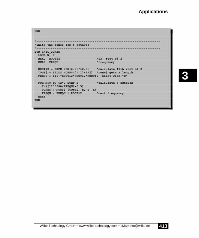
Applications
Wilke Technology GmbH • www.wilke-technology.com • eMail: [email protected]
3
413
ENDIFEND
'--------------------------------------------------------------------'inits the tones for 6 octaves'--------------------------------------------------------------------SUB INIT_TONES LONG N, K REAL ROOT12 '12. root of 2 REAL FREQU 'frequency
ROOT12 = EXPE (LN(2.0)/12.0) 'calculate 12th root of 2 TONE$ = FILL$ (CHR$(0),12*6*2) 'tone$ gets a length FREQU = 110.*ROOT12*ROOT12*ROOT12 'start with "C"
FOR N=0 TO 62*2 STEP 2 'calculate 6 octaves K=((1250000/FREQU)+0.5) TONE$ = NTOS$ (TONE$, N, 2, K) FREQU = FREQU * ROOT12 'next frequency NEXTEND

Applications
Wilke Technology GmbH • www.wilke-technology.com • eMail: [email protected]
3
414
Empty Page

Wilke Technology GmbH • www.wilke-technology.com • eMail: [email protected] 415
About this manual 1Device driver 2Applications 3BASIC Tiger® Graphic Toolkit 4Frequently asked questions 5Index 6Appendix 7

BASIC-Tiger® Graphic-Toolkit
Wilke Technology GmbH • www.wilke-technology.com • eMail: [email protected]
4
417
4 BASIC-TIGER® Graphic Toolkit

BASIC-Tiger® Graphic-Toolkit
Wilke Technology GmbH • www.wilke-technology.com • eMail: [email protected]
4
418
General view of the BASIC-Tiger® Graphic Toolkit

BASIC-Tiger® Graphic-Toolkit
Wilke Technology GmbH • www.wilke-technology.com • eMail: [email protected]
4
419
The BASIC-TIGER® Graphic Toolkit is a hardware platform for the fast developmentof applications with graphic LCD with the BASIC-Tiger®. It is assumed that you havethe development system BASIC-Tiger® version 4.0 or later and are familiar withTiger-BASIC®.
The BASIC-TIGER® Graphic Toolkit provides the following peripheral components.
• Graphic LC display with 240 x 128 pixels and CFL back-lighting• analog Touchpanel• 2 serial RS232 interfaces, one optional as PC mouse port• mini keyboard with 8 keys• printer port• 4 analog inputs with BNC sockets and input voltage limitation• shaft encoder for menu scrolling, for example• power supply input for 8-12 V DC• photoresistor
The BASIC-TIGER® Graphic Toolkit can be equipped with both BASIC-Tiger® Amodules and BASIC-Tiger® T modules (via adapter). The BASIC-Tiger® modulemay not, however, be equipped with RS-232 drivers.
The long row of jumpers to the left of the module is normally equipped with jumperswhich create a connection to the mini keyboard of the BASIC-Tiger® GraphicToolkit. If all jumpers are removed the BASIC-Tiger® terminal can be connected atthis plug connector.

BASIC-Tiger® Graphic-Toolkit
Wilke Technology GmbH • www.wilke-technology.com • eMail: [email protected]
4
420
The following components are connected to the module on the board. Theconnections marked 'jumper' share the pin with other devices and can be switchedand/or disconnected accordingly:
Component Pin (logicalname)
Remark
Graphic LCD L60...L67L80...L83L84L85L86L71
Data busContor line (fixed connection)DISP_OFF (via Jumper)Font-Select (via Jumper)Inverse (via Jumper)LCD-Reset (via Jumper)
Extended I/O's L60...L67L33,34,35
Data bus and control lines. Ext. I/O's are used forkeyboard and Touchpanel. Jumper (otherwiseBASIC-Tiger® terminal connection)
Touchpanel ext. I/O,AN2
switch VCC, GND, analog measuring point analogmeasuring input (Jumper)
Keyboard =ext. I/O 8 keys
Shaft encoder L72,73, L87 2 x impulse and axis of the shaft encoder
Printer L60...L67L70,71
Data busControl lines '-strobe', 'busy'
DB9-SER0 L90,91,92,95 via RS-232 driver (jumper: DB9-Maus)
DB9-SER1 L93,94 via RS-232 driver
BNC AN0BNC AN1BNC AN2BNC AN3
AN0AN1AN2AN3
Analog input AN0Analog input AN1Analog input AN2 (Jumper Touchpanel)Analog input AN3 (Jumper LDR)
Buzzer L42 Key click, beep
LDR AN3 Optical sensor (jumper)
PC/RUN mode PC Sliding switch
Vref adjustable Vref
Reset key RESET
unused pins L36, L37,L40
(used by BASIC-Tiger® Terminal)free

Graphic LC display
Wilke Technology GmbH • www.wilke-technology.com • eMail: [email protected]
4
421
Graphic LC display
Control pins for the graphic LCD

BASIC-Tiger® Graphic-Toolkit
Wilke Technology GmbH • www.wilke-technology.com • eMail: [email protected]
4
422
A device driver is available to drive the graphic LCD: LCD-6963. More detailedinformation on the device -driver for the graphic display can be found in the section"LCD Graphic Display" of the BASIC-Tiger® Device Drive Manual.
Apart from different LCD sizes, the Graphic LCD with processor T6963 has twosettings which require a different drive by the device driver. The logic level at thecontrol pin 'Font-Select' causes
• at low-level, the characters are shown in a matrix 8x8-pixel and all 8 bits ofevery graphic byte appear as pixels. LCD type: 4
• at high-level, the characters are shown in a matrix 6x8-pixel and only thelower 6 bits of every graphic byte appear as pixels. LCD-type: 6
The control pins of the LCD must be set accordingly and during installation of thedevice driver ‘LCD-6963.TDD‘ the suitable LCD-type must be specified according tothe settings used for the Font-Select pin (type 4 or type 6). This is guaranteed in theexamples by integrating the Include files in the right order and by the calling'init_LCDpins'. 'init_LCDpins' can be found in GR_TK1.INC.
There is one Include file for each of both modes '6x8-Pixel-font' and '8x8-Pixel-font'for the LCD type of the BASIC-TIGER® Graphic Toolkit. The two Include filesLCD_4.INC and LCD_6.INC contain the suitable definitions for the LCD-type 4 andLCD-type 6. In the examples for the BASIC-TIGER® Graphic Toolkit an I/O-pin ofthe BASIC-Tiger® module is used as a control pin for the Font-Select pin on the LCD(see LC-Display-Jumperblock).
The Include file for the BASIC-TIGER® Graphic Toolkit GR_TK1.INC containsdefinitions for the Toolkit and the subroutine 'init_LCDpins'. It will always beinserted after the Include file of the LCD type.
For your own projects with hardware which differs from the BASIC-TIGER®Graphic Toolkit as well as other LCD types the existing Include files can be used as amodel.
The Font-Select pins influence not only the character set but also the pixel distributionof the graphic area. In the mode '6x8-font' only the lowest 6 bits of every graphic bytewill be used for the graphic. To ensure that a graphic appears correctly in the LCD, itis cut into strips before transmission (function GRAPHIC_EXP $). The 30 bytecolumns are converted into 40 byte columns and accordingly more bytes aretransmitted for a graphic.
The LCD of the type 7 with a resolution of 128x64 has 21 text columns in the mode'6x8-font'. However, 22 byte columns are counted in the graphic display mode since128 cannot be divided by 6 and 2 pixel columns would be not controllable. This

Graphic LC display
Wilke Technology GmbH • www.wilke-technology.com • eMail: [email protected]
4
423
circumstance arises if the function GRAPHIC_EXP$ is used to adjust the graphic tothe 6 x8 mode.
Note: graphic LCDs can differ in their pixel form. Circles then become for exampleellipses on some LCDs if the pixels are not square.The assignments differ from model to model.
Obtain documents for your LCD before you include a model in your plans.
The following steps ensure that the LCD is integrated correctly in the exampleprograms:
Source text Meaning
1. #include LCD_4.INC
or #include LCD_6.INC
contains definitions suitable for 8x8 character setwith 8 bits per graphic pixelscontains definitions suitable for 6x8 character setwith 6 bits per graphic pixel
2. #include GR_TK1.INC contains definitions suitable for the BASIC-TIGER® Graphic Toolkit and the subroutine'init_LCDpins'.
3. call init_LCDpins initializes LCD control pins according toLCD_4.INC and LCD_6.INC
4. install_DEVICE „LCD-6963.TDD“, Parameter...
installs the device driver. The parameterLCD_TYPE is defined in LCD_4.INC orLCD_6.INC.

BASIC-Tiger® Graphic-Toolkit
Wilke Technology GmbH • www.wilke-technology.com • eMail: [email protected]
4
424
LCD connection:
GND 1 2 VCC
Contrast 3 4 C/-D
-WR 5 6 -RD
D0 7 8 D1
D2 9 10 D3
D4 11 12 D5
D6 13 14 D7
-CE 15 16 Reset
-15 17 18 ON
FSlow: 8x8
high: 6x8
19 20 -Reverselow: whitehigh: blackcharacters
LCD-Jumper
LCD Pin Pin BASIC-Tiger®
backlight ON 1 2 L84
Font-Select 3 4 L85
Reverse 5 6 L86
LCD-Reset 7 8 L71
LCD-Reset 9 10 Reset
Note: if LCD-Reset is jumpered on the reset network of the BASIC-TIGER® GraphicToolkit then you must take into account that the reset network only gets a reset with akeystroke, not however when the BASIC-TIGER® Graphic Toolkit is switched on.The Reset-pins of the BASIC-Tiger® A and BASIC-Tiger® T are only inputs, noreset signal is output externally. The Tiger module gives the LCD a Reset in theexample programs via the pin L71.

Graphic LC display
Wilke Technology GmbH • www.wilke-technology.com • eMail: [email protected]
4
425
The wiring diagram shows everything needed to connect a graphic LCD with back-lighting to the BASIC-Tiger®. On the BASIC-TIGER® Graphic Toolkit the voltageconverter and the DC/DC-converter for the contrast voltage is located on the PCBbelow the LCD.
BATT45VC C 46
Vref 43AGN D 44
Alarm 38
AN 1 40
L613
AN 0 39
WAKE1
L41/PC37
L602
L40 36
AN 3 42
L3330
L8620
L42 35
L8519
AN 241
L8418
L37 34
L8317
L3633
L8216L35 32L8115
L34 31
L8014 L73(PWM )13
L90/TXD 0 24
L72(PWM )12
L8721
L7111
R eset22
L7010
GN D23
L679
L95/R TS029
L668
L92/C TS026
L657
L94/R XD 1 28
L646
L93/TXD 1 27
L635L624
L91/R XD 025
U 1T I G E R_A
FGN
D1
VC
C3
WR
5
C/-
D8
RD
6
CE
7
D0
11
D1
12
D2
13
D3
14
D4
15
D5
16
D6
17
D7
18
GN
D2
FS19
RE
S10
VE
E4
nc9
RV
S20
L CD 1
L CD E G 24D 70N CW
VC C
VC
CV
EE
AM P+6 AM P-7
C M PR +9C M PR -10
AM P OU T4
VR EF 8
D R VC OLL 15
SWC OLL 16
C T12
D A 2
D K 1
IPK14
SW EM3
U 2U A 78S40P C(16)
R1
47R
Q 1BC556B
R2220R
L 1
100uH
D 11N 4148
C3220u/25V
C2220u/6V
C10u1
C4820p
VC C
R41k
R515k
R6
1k
V E E
1 23 4
X 1D C/D CVC C
12
J1ba c klight
b ack l ig h t co n v erter
co n tras t v o l tag e s rc: -1 5 V

BASIC-Tiger® Graphic-Toolkit
Wilke Technology GmbH • www.wilke-technology.com • eMail: [email protected]
4
426
Large numbersMany applications use large characters for the representation on the graphic LCD.The LCD modules, however, have no internal character set with large characters oreven a character set with an adjustable size. If it is a fixed text, then this is simply acomponent of the display mask. However, if the text should be able to be changed fora numerical display, the application program must compile the numbers during therunning time.
The program example BIGDIGITS.TIG demonstrates how large numbers arerepresented in a simple form. The character set is present as a graphic in a bitmap file.The size of the characters is known and the same for all characters. The subroutine'BigDigits' compiles a number by copying the 4 numbers into the output string withthe instruction GRAPHIC_COPY. On request, the number can be output with anoperational sign. The subroutine uses an index in a list of fonts. The shaft encoder isused to adjust the number. A pressure on the shaft encoder changes the character setby indexing the index in the font list.
The following extensions to the example 'BigDigits' are conceivable:
• more characters (letters, special signs)• subroutine uses variables for the font sizes and the copying position instead
of fixed numbers• in a proportionally spaced font every character has an individual density
(breadth)• scalable fonts in vector graphic

Large numbers
Wilke Technology GmbH • www.wilke-technology.com • eMail: [email protected]
4
427
Program example:
'--------------------------------------------------------------------'Name: BIGDIGIT.TIG'Shows on the graphic LCD the count of the rotary encoder'using big numbers from a graphical font. Pressing the'encoder axis changes the font index, thus another font appears'--------------------------------------------------------------------'Note: connect L71 to reset LCD'--------------------------------------------------------------------user_var_strict 'variables must be declared#include DEFINE_A.INC 'general defines#include UFUNC3.INC 'definitions of user function codes#include LCD_4.INC 'definitions for LCD Typ 4#include GR_TK1.INC 'definitions for Graphic Toolkit#include BIGDIGIT.INC 'big digits for graphic LCD
STRING Screen$(GR_SIZE), tmp$(GR_SIZE)
'--------------------------------------------------------------------TASK MAIN BYTE bEncKey LONG dwEnc LONG fontidx
call Init_LCDpins 'init LCD
install_device #LCD2, "LCD-6963.TDD",0,0,0EEH,4,150,11H install_device #TA, "TIMERA.TDD",3,156 'time base 1kHz install_device #ENC, "ENC1_723.TDD" 'encoder port 7, pins 2+3
Screen$=FILL$ ("<0>",GR_SIZE) 'init string
dir_pin P_ENC_KEY, PIN_ENC_KEY, 1'key pin as input put #LCD2, CURSOR_OFF 'text cursor off put #ENC, 0 'start encoder
fontidx = 0 while 0 = 0 'endless loop get #ENC, #0, 0, dwEnc 'read turned steps print #LCD2, "<1Bh>A<3><2><0F0h>Encoder:"; dwEnc; " "; tmp$ = fill$ ( "<0>", GR_SIZE )'area to copy digits ' DEST, no., Font-Index, Digits, X, Y sign call printn_to_stri ( tmp$, dwEnc, fontidx, 4, 20, 30, 1 ) put #LCD2, #1, tmp$, 0, 0, GR_SIZE 'show graphic on LCD
ll_iport_in P_ENC_KEY, bEncKey, M_ENC_KEY if bEncKey <> M_ENC_KEY then 'if encoder pressed fontidx = fontidx + 1 'change font if fontidx > 4 then fontidx = 0 endif bEncKey = M_ENC_KEY + 1 '<> M_ENC_KEY is pressed

BASIC-Tiger® Graphic-Toolkit
Wilke Technology GmbH • www.wilke-technology.com • eMail: [email protected]
4
428
while bEncKey <> M_ENC_KEY 'wait until released ll_iport_in P_ENC_KEY, bEncKey, M_ENC_KEY endwhile endif wait_duration 200 'loop speed endwhileEND

Mini keyboard
Wilke Technology GmbH • www.wilke-technology.com • eMail: [email protected]
4
429
Mini keyboard
Jumper for extended I/O mini keyboard

BASIC-Tiger® Graphic-Toolkit
Wilke Technology GmbH • www.wilke-technology.com • eMail: [email protected]
4
430
There is a single-column mini keyboard with eight keys on the BASIC-TIGER®Graphic Toolkit. The keys can, for example, be assigned functions which are shownon the graphic LCD in the lower area.
The column address of this keyboard is set by the PAL to the physical address 88h.The keyboard is can be addressed on the software-side as of the logical address 98hwith a predefined USER_EPORT OFFSET of -10H. From the point of view of theBASIC-Tiger® the keyboard consists of extended inputs. The keyboard thus occupiesthe pins L60...L67 (data bus) as well as the lines L33 (Aclk) and L35 (INE).
The example program MINIKEY.TIG reads the scan codes of the keyboard. Thefollowing jumpers must hereby be set:

Mini keyboard
Wilke Technology GmbH • www.wilke-technology.com • eMail: [email protected]
4
431
Jumper row for keyboard/terminal connection
G N D
V CC
P 33P 34P 35P 36P 37
A c lkD c lkIN E
Terminal connector
1 23 45 67 89 10
11 1213 1415 1617 1819 2021 2223 2425 26
J4ID C26
G19
D I R1
A 12
B118
A 23
B217
A 34
B316
A 45
B415
A 56
B5 14
A 67
B613
A 78
B7 12
A 89
B811
U 1SN 74H C245
123456789
R522K
4 13 2
4 13 2
J8
4 13 2
J9 4 13 2
J10
4 13 2
J11
4 13 2
J124 1
3 2J13
4 13 2
J14
G N D
m in i k e y b o a rd
P 33P 34P 35P 36P 37
V CC
G N D
I12
I23
I34
I45
I56
I67
I78
I89
I910
I1011
I1123
I1214
CL K1
O E13
O 122
O 221
O 3 20
O 419
O 5 18
O 617
O 7 16
O 815
IC6P A L 20R8B
IN E
T ouc hsc r e e nK e y boa rdG
1
CL K11
1D3
1Q2
2D4
2Q5
3D7
3Q 6
4D8
4Q9
5D13
5Q 12
6D14
6Q15
7D17
7Q 16
8D18
8Q19
IC7SN 74H C377
A c lk
G N D
G N D
BA T T45
V CC46
V r e f43
A G N D44
A la rm 38
A N 140
L 613
A N 039
W A K E1
L 41/P C37
L 602
L 40 36
A N 342
L 3330
L 8620
L 4235
L 8519
A N 241
L 8418
L 37 34
L 8317
L 3633
L 8216 L 35
32L 81
15
L 3431
L 8014
L 73( P W M )13
L 90/T X D 024
L 72( P W M )12
L 8721
L 7111
Re se t22
L 7010
G N D23
L 679
L 95/RT S029
L 668
L 92/CT S026
L 657
L 94/RX D 128
L 646
L 93/T X D 127
L 635 L 624
L 91/RX D 0 25
IC1BA SIC-T IG E R- A
jumper or
D 0D 1D 2D 3D 4D 5D 6D 7
D 0D 1D 2D 3D 4D 5D 6D 7
D 0D 1D 2D 3D 4D 5D 6D 7
8 k eys
addres s latch

BASIC-Tiger® Graphic-Toolkit
Wilke Technology GmbH • www.wilke-technology.com • eMail: [email protected]
4
432
Jumper for keyboard / Terminal connector
With set jumpers the internal mini keyboard is connected to the BASIC-Tiger®module. The BASIC-Tiger® terminal can alternatively be connected with a flat cable.
Caution: if only the jumper 'INE' is pulled then know the keyboard's driver canswitch an active level on the lines of port 6 switch and thus disturb other connectedcomponents. With VCC level the driver is de-activated.
Note: the device driver LCD1.TDD is reprogrammed to scan only one keyboardcolumn as keys, all other (non-existent) columns will be regarded as DIP-switches.Up until reprogramming, however, characters may have already reached the keyboardbuffer. These must therefore be deleted before the programme uses the keyboard.

Serial interfaces
Wilke Technology GmbH • www.wilke-technology.com • eMail: [email protected]
4
433
Program example:
'--------------------------------------------------------------------'Name: MINIKEY.TIG'Shows on LCD the scan code of the pressed key'--------------------------------------------------------------------user_var_strict 'variables must be declared#include DEFINE_A.INC 'general defines#include UFUNC3.INC 'definitions of user function codes#include LCD_4.INC 'definitions for LCD Typ 4#include GR_TK1.INC 'defines for Graphic Toolkit
TASK Main 'begin task MAIN BYTE i STRING Char$(1)
call Init_LCDpins 'init LCD pins 'LCD-4=240x128, 150 KB/s INSTALL DEVICE #LCD2,"LCD-6963.TDD",0,0,0EEH,LCD_TYPE,150,11H'install LCD1 device driver for keyboard (BASIC Tiger) INSTALL DEVICE #LCD,"LCD1.TDD", & 0,0,0,0,0,0,0eeh,0,0eeh,0,0,0eeh,0ffh,0ffh'install LCD1 device driver for keyboard (TINY Tiger)' INSTALL DEVICE #LCD, "LCD1.TDD", &' 0,0,0,0,0,0,80h,8,0eeh,0,0,0eeh,0ffh,0ffh
put #lcd ,& 'scan one row for keys "<1bh>D<16><0><0><0><0><0><0><0><0><0><0><0><0><0><0><0><0><0f0H>" 'format pattern for dec and hex wait_duration 50 'wait until scan uses new table put #LCD, #0, #UFCO_IBU_ERASE, 0 'clear from input up to now
while 0 = 0 print #LCD2, "<1bh>A<0><0><0F0h>"; for i = 1 to 16 get #LCD, #i, 1, char$ using "UH<2><2> 0.0.0.0.2" print_using #LCD2,asc(Char$); next endwhile print #LCD2, "press one of 8 keys"; using "UD<4><1> 0.0.0.0.4UH<2><2> 0.0.0.0.2" while 0 = 0 'endless loop get #LCD, #0, 1, Char$ 'wait for a character if Char$ <> "" then print_using #LCD2, "<1Bh>A<3><9><0F0h>Key = "; asc(Char$);& " ($"; ASC(Char$); ")";" " endif endwhileEND

BASIC-Tiger® Graphic-Toolkit
Wilke Technology GmbH • www.wilke-technology.com • eMail: [email protected]
4
434
Serial interfaces
Jumper of the serial interface

Serial interfaces
Wilke Technology GmbH • www.wilke-technology.com • eMail: [email protected]
4
435
The BASIC-TIGER® Graphic Toolkit leads both RS232-interfaces over drivers toDB-plug connector. The serial interface 0 can alternatively be set to on the DB9-connector 'SER0' or the PC mouse port by jumpers. 'Mouse' RTS0 and CTS0 will beconnected in the jumper position.
MouseA special serial device driver must be used to run a Microsoft mouse on the BASIC-Tiger® (SER1C_xxx.TDD). This driver edits and provides the data supplied by themouse. The following example program shows the use of the serial mouse driver. Themovements and keystrokes are displayed on the LCD in a text form. A furtherexample then shows the use of the mouse in a graphic application.
Caution: No data may be sent on SER0 during the download process. Don't movethe mouse during the downloads or remove the plug.

BASIC-Tiger® Graphic-Toolkit
Wilke Technology GmbH • www.wilke-technology.com • eMail: [email protected]
4
436
Program example:
'--------------------------------------------------------------------'Name: MOUSE1.TIG'Demonstrates how to read mouse data.'Shows mouse data (on text screen)'--------------------------------------------------------------------'Note: connect L71 to reset LCD'--------------------------------------------------------------------user_var_strict 'variables must be declared#include DEFINE_A.INC 'general defines#include UFUNC3.INC 'definitions of user function codes#include LCD_4.INC 'definitions for LCD Typ 4#include GR_TK1.INC 'definitions for Graphic Toolkit
LONG key 'mouse keysLONG mx,my 'mouse coordinates
'--------------------------------------------------------------------'main program'--------------------------------------------------------------------TASK Main LONG x, y
call Init_LCDpins
install_device #LCD2,"LCD-6963.TDD",0,0,0EEH,4,150,11H 'special mouse serial device driver install_device #SER,"SER1C_K1.TDD",& "M", DP_8N, YES, BD_38_400, DP_8E, YES
print #LCD2, "<1bh>A<0><0><0f0h>please move mouse"; print #LCD2, "<1bh>A<0><1><0f0h>and press mouse keys";
while 0 = 0 'endless loop get #SER, #12H, 4, key 'read mouse state if key bitand 4 <> 0 then 'if valid first mouse byte get #SER, #10H, 4, x 'get mouse increments (if any) get #SER, #11H, 4, y 'get mouse increments (if any) print #LCD2, "<1bh>A<5><6><0f0h>x:";x;" y:";y;" ";
if key bitand 1 <> 0 then 'check for RIGHT mouse key print #LCD2, "<1bh>A<15><8><0f0h>right key"; else print #LCD2, "<1bh>A<15><8><0f0h> "; endif if key bitand 2 <> 0 then 'check for LEFT mouse key print #LCD2, "<1bh>A<4><8><0f0h>left key"; else print #LCD2, "<1bh>A<4><8><0f0h> "; endif endif wait_duration 50
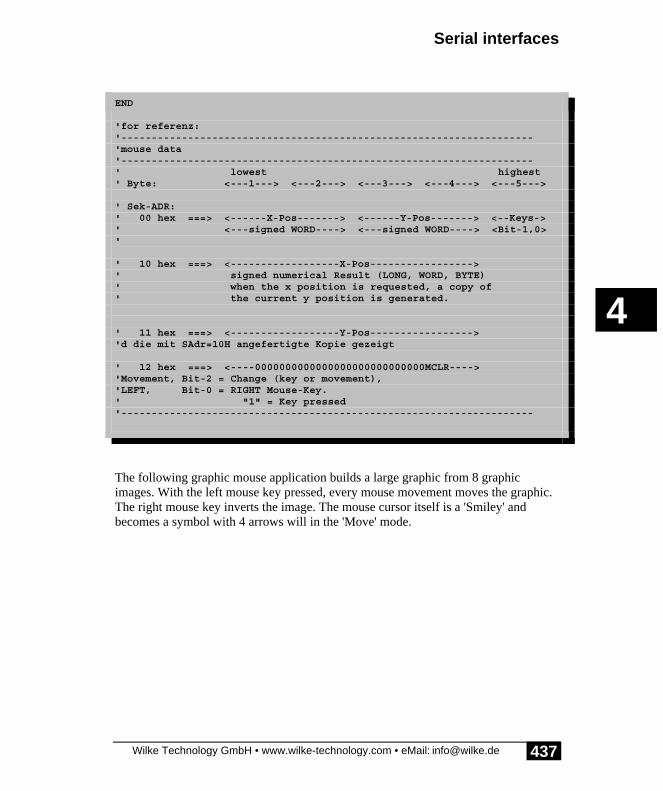
Serial interfaces
Wilke Technology GmbH • www.wilke-technology.com • eMail: [email protected]
4
437
endwhileEND
'for referenz:'--------------------------------------------------------------------'mouse data'--------------------------------------------------------------------' lowest highest' Byte: <---1---> <---2---> <---3---> <---4---> <---5--->
' Sek-ADR:' 00 hex ===> <------X-Pos-------> <------Y-Pos-------> <--Keys->' <---signed WORD----> <---signed WORD----> <Bit-1,0>'
' 10 hex ===> <------------------X-Pos----------------->' signed numerical Result (LONG, WORD, BYTE)' when the x position is requested, a copy of' the current y position is generated.
' 11 hex ===> <------------------Y-Pos----------------->'d die mit SAdr=10H angefertigte Kopie gezeigt
' 12 hex ===> <----0000000000000000000000000000MCLR---->'Movement, Bit-2 = Change (key or movement),'LEFT, Bit-0 = RIGHT Mouse-Key.' "1" = Key pressed'--------------------------------------------------------------------
The following graphic mouse application builds a large graphic from 8 graphicimages. With the left mouse key pressed, every mouse movement moves the graphic.The right mouse key inverts the image. The mouse cursor itself is a 'Smiley' andbecomes a symbol with 4 arrows will in the 'Move' mode.

BASIC-Tiger® Graphic-Toolkit
Wilke Technology GmbH • www.wilke-technology.com • eMail: [email protected]
4
438
Program example:
'--------------------------------------------------------------------'Name: MOUSE2.TIG'Shows a mouse pointer,'with pressed left mouse button: moves background,'with pressed right mouse button: inverts background picture'--------------------------------------------------------------------'Note: connect L71 to reset LCD'--------------------------------------------------------------------user_var_strict 'variables must be declared#include DEFINE_A.INC 'general defines#include UFUNC3.INC 'definitions of user function codes#include LCD_4.INC 'definitions for LCD Typ 4#include GR_TK1.INC 'definitions for Graphic Toolkit
LONG n, key, mscaleLONG x, yLONG mx,my, mxp,myp, mx2n,my2n, mx2p,my2p'mouse coordinatesLONG deltax, deltay, deltax2, deltay2 'effective movements on SCREENLONG xabs,yabs, xabs2,yabs2 'abs shift in big$LONG ptrSTRING big$(31K) 'Big Area for 8 screens 240 x 128STRING Screen$(GR_SIZE)
DATALABEL L_CURS_A1,L_CURS_A2,L_CURS_B1,L_CURS_B2DATALABEL PICT1, PIC_240_256, USE_MOUSE
'--------------------------------------------------------------------'main program'load drivers, initialize vars, start tasks'--------------------------------------------------------------------TASK MainL_CURS_A1:: DATA FILTER "CURS_A1.BMP","GRAPHFLT",0 '32L_CURS_A2:: DATA FILTER "CURS_A2.BMP","GRAPHFLT",0 'x 32L_CURS_B1:: DATA FILTER "CURS_B1.BMP","GRAPHFLT",0 '32L_CURS_B2:: DATA FILTER "CURS_B2.BMP","GRAPHFLT",0 'x 32
'pictures that are combined to a large backgroundPICT1:: DATA FILTER "SS1_002.BMP","GRAPHFLT",0 DATA FILTER "SS1_004.BMP","GRAPHFLT",0
DATA FILTER "SS1_018.BMP","GRAPHFLT",0 DATA FILTER "SS1_025.BMP","GRAPHFLT",0
DATA FILTER "SS1_013.BMP","GRAPHFLT",0 DATA FILTER "SS1_024.BMP","GRAPHFLT",0

Serial interfaces
Wilke Technology GmbH • www.wilke-technology.com • eMail: [email protected]
4
439
DATA FILTER "SS1_014.BMP","GRAPHFLT",0 DATA FILTER "SS1_015.BMP","GRAPHFLT",0USE_MOUSE:: DATA FILTER "MDEM_T02.BMP","GRAPHFLT",0 '"Use Mouse" 176 x 32
call Init_LCDpins 'init LCD 'LCD-4=240x128, 150 KB/s install_device #LCD2,"LCD-6963.TDD",0,0,0EEH,4,150,11H 'special mouse serial device driver install_device #SER,"SER1C_K1.TDD",& "M", DP_8N, YES, BD_38_400, DP_8E, YES
put #LCD2, CURSOR_OFF 'text cursor off screen$ = fill$ ( "<0>", GR_SIZE ) 'init screen$ big$ = fill$ ("<00>",31K) 'iate big area to "white" dots ptr = pict1 ' 1. picture
'--------------------------------------------------------------------'build a big string containing 8 screens of 240 x 128 pixels'--------------------------------------------------------------------
' !-----!-----!' ! 0 ! 1 !' !-----!-----!' ! 2 ! 3 !' !-----!-----!' ! 4 ! 5 !' !-----!-----!' ! 6 ! 7 !' !-----!-----! for y = 0 to 3*128 step 128 for x = 0 to 240 step 240 graphic_copy ( & big$, & 'destination ptr, & 'source 480,512, & 'destination format X,Y, & 'destination position 240,128, & 'source size 0,0, & 'from source position 240,128, & 'source window 0) 'mode ptr=PTR+240*128/8 next next
mscale = 1 'mouse scaling factor xabs = 64 'abs shift of BIG into SCREEN yabs = 128
mx = 120 * mscale 'mouse-X2 prev. position * factor my = 64 * mscale mx2p = mx 'previous mouse x2-position my2p = my
'show initial Picture

BASIC-Tiger® Graphic-Toolkit
Wilke Technology GmbH • www.wilke-technology.com • eMail: [email protected]
4
440
'first cut a window from big$ graphic_copy ( & screen$, & 'destination big$, & 'source 240,128, & 'destination format 0,0, & 'destination position 480,512, & 'source size xabs,yabs, & 'from source position 240,128, & 'source window 0) 'mode'put text use-mouse graphic_copy ( & screen$, & 'destination use_mouse, & 'source 240,128, & 'destination format 16,8, & 'destination position 176,32, & 'source size 0,0, & 'from source position 176,32, & 'source window 0) 'mode Punch'put mouse cursor into it graphic_copy ( & screen$, & 'destination L_CURS_A2, & 'source 240,128, & 'destination format mx,my, & 'destination position 32,32, & 'source size 0,0, & 'from source position 32,32, & 'source window 2) 'mode AND graphic_copy ( & screen$, & 'destination L_CURS_A1, & 'source 240,128, & 'destination format mx,my, & 'destination position 32,32, & 'source size 0,0, & 'from source position 32,32, & 'source window 1) 'mode OR put #LCD2, #1, screen$, 0, 0, GR_SIZE
'--------------------------------------------------------------------'mouse data'--------------------------------------------------------------------' lowest highest' Byte: <---1---> <---2---> <---3---> <---4---> <---5--->
' Sek-ADR:' 00 hex ===> <------X-Pos-------> <------Y-Pos-------> <--Keys->' <---signed WORD----> <---signed WORD----> <Bit-1,0>'
' 10 hex ===> <------------------X-Pos----------------->' signed numerical Result (LONG, WORD, BYTE)' when the x position is requested, a copy of

Serial interfaces
Wilke Technology GmbH • www.wilke-technology.com • eMail: [email protected]
4
441
' the current y position is generated.
' 11 hex ===> <------------------Y-Pos----------------->'d die mit SAdr=10H angefertigte Kopie gezeigt
' 12 hex ===> <----0000000000000000000000000000MCLR---->'Movement, Bit-2 = Change (key or movement),'LEFT, Bit-0 = RIGHT Mouse-Key.' "1" = Key pressed'--------------------------------------------------------------------
while 0 = 0 'endless loop get #SER, #12H, 4, key 'read mouse state if key bitand 4 <> 0 then get #SER, #10H, 4, x 'get Mouse increments (if any) get #SER, #11H, 4, y 'get Mouse increments (if any)
mx2n = limit (mx2p+x,0,(240-32)*mscale)'new x-position my2n = limit (my2p+y,0,(128-32)*mscale)'new y-position
'effective Delta2's: deltax2 = mx2n - mx2p ' prev deltay2 = my2n - my2p ' prev
mxp = mx 'previous mouse x-position myp = my mx2p = mx2n 'previous mouse x2-position my2p = my2n
mx = (mx2n-deltax2)/mscale 'new actual mous position on LCD my = (my2n-deltay2)/mscale
deltax = mx - mxp 'effective delta-Y deltay = my - myp
if key bitand 2 <> 0 then 'left mouse button shifts BIG$ xabs = limit (xabs - deltax, 0, 240) yabs = limit (yabs - deltay, 0, 384) endif
'--------------------------------------------------------------------'cut a window from big$ graphic_copy ( & screen$, & 'destination big$, & 'source 240,128, & 'destination format 0,0, & 'destination position 480,512, & 'source size xabs,yabs, & 'from source position 240,128, & 'source window 0) 'mode if key bitand 1 <> 0 then 'check for RIGHT mouse key screen$ = invert ( screen$, 0, GR_SIZE) 'invert screen endif

BASIC-Tiger® Graphic-Toolkit
Wilke Technology GmbH • www.wilke-technology.com • eMail: [email protected]
4
442
'--------------------------------------------------------------------'copy message into screen: "Use Mouse" graphic_copy ( & screen$, & 'destination use_mouse, & 'source 240,128, & 'destination format 16,8, & 'destination position 176,32, & 'source size 0,0, & 'from source position 176,32, & 'source window 0) 'mode Punch
'-------------------------------------------------------------------- if key bitand 2 = 0 then 'check for LEFT mouse key'copy cursor "smile" (LEFT mouse key NOT pressed) into SCREEN$ graphic_copy ( & screen$, & 'destination L_CURS_A2, & 'source 240,128, & 'destination format mx,my, & 'destination position 32,32, & 'source size 0,0, & 'from source position 32,32, & 'source window 2) 'mode AND graphic_copy ( & screen$, & 'destination L_CURS_A1, & 'source 240,128, & 'destination format mx,my, & 'destination position 32,32, & 'source size 0,0, & 'from source position 32,32, & 'source window 1) 'mode OR'-------------------------------------------------------------------- else'copy cursor "arrows" (LEFT mouse key IS pressed) into SCREEN$ graphic_copy ( & screen$, & 'destination L_CURS_B2, & 'source 240,128, & 'destination format mx,my, & 'destination position 32,32, & 'source size 0,0, & 'from source position 32,32, & 'source window 2) 'mode AND graphic_copy ( & screen$, & 'destination L_CURS_B1, & 'source 240,128, & 'destination format mx,my, & 'destination position 32,32, & 'source size 0,0, & 'from source position 32,32, & 'source window 1) 'mode OR
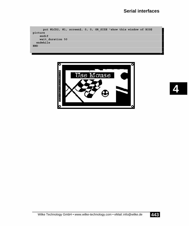
Serial interfaces
Wilke Technology GmbH • www.wilke-technology.com • eMail: [email protected]
4
443
endif put #LCD2, #1, screen$, 0, 0, GR_SIZE 'show this window of BIG$picture endif wait_duration 50 endwhileEND

BASIC-Tiger® Graphic-Toolkit
Wilke Technology GmbH • www.wilke-technology.com • eMail: [email protected]
4
444
Printer portA parallel printer can be connected at the printer port of the BASIC-TIGER® GraphicToolkit. The lines L70 for '-strobe' and L71 for 'busy' are used along with the data busL60...L67.

Printer port
Wilke Technology GmbH • www.wilke-technology.com • eMail: [email protected]
4
445
Program example:
'--------------------------------------------------------------------'Name: PRINTER1.TIG'Output on printer port'--------------------------------------------------------------------user_var_strict 'variables must be declared#include DEFINE_A.INC 'general defines#include UFUNC3.INC 'definitions of user function codes#include LCD_4.INC 'definitions for LCD Typ 4#include GR_TK1.INC 'defines for Graphic Toolkit
TASK Main call Init_LCDpins 'init LCD pins 'LCD-4=240x128, 150 KB/s INSTALL DEVICE #LCD2,"LCD-6963.TDD",0,0,0EEH,LCD_TYPE,150,11H INSTALL_DEVICE #2,"PRN1_k4.TDD" 'printer port driver
PRINT #LCD2, "<1Bh>A<1><2><0F0h>print test on printer port" PRINT #2, "<10><13>Print test on parallel port" PRINT #2, " Test finished<12>";END

BASIC-Tiger® Graphic-Toolkit
Wilke Technology GmbH • www.wilke-technology.com • eMail: [email protected]
4
446
Analog inputsThe analog inputs of the BASIC-TIGER® Graphic Toolkit lead over operationamplification circuits switched as impedance transformers and which limit thevoltages at the four BASIC-Tiger® analog inputs.
The analog channel 2 can be switched either on the BNC-socket or on the Touchpanelby means of jumpers. The analog channel 3 can be jumpered either on the BNC-socket or the photoresistor (LDR).
Analogchannel
either or
channel 2 BNC Touchpanel
Channel 3 BNC Photosensor (LDR)
An adjustable reference voltage source is available which is connected directly withthe Vref-pin of the BASIC-Tiger®. The stable voltage for the Touchpanel is alsoderived from this reference voltage.
Some of the following example programs use the analog inputs as signal sources.

Analog inputs
Wilke Technology GmbH • www.wilke-technology.com • eMail: [email protected]
4
447
Analog part of the BASIC-Tiger® Graphic Toolkit

BASIC-Tiger® Graphic-Toolkit
Wilke Technology GmbH • www.wilke-technology.com • eMail: [email protected]
4
448
Photoresistor
Jumper and setting Vref

Photoresistor
Wilke Technology GmbH • www.wilke-technology.com • eMail: [email protected]
4
449
The photoresistor is connected to analog channel 3 of the BASIC-Tiger® via ajumper. The programme FOTO_R.TIG, which represents the voltage measured valuein large numbers, is used for demonstration purposes here.
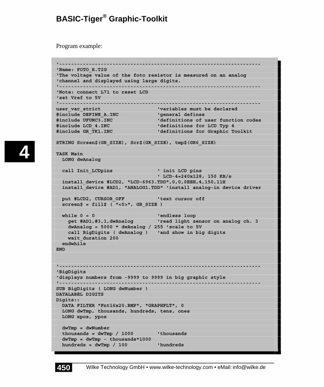
BASIC-Tiger® Graphic-Toolkit
Wilke Technology GmbH • www.wilke-technology.com • eMail: [email protected]
4
450
Program example:
'--------------------------------------------------------------------'Name: FOTO_R.TIG'The voltage value of the foto resistor is measured on an analog'channel and displayed using large digits.'--------------------------------------------------------------------'Note: connect L71 to reset LCD'set Vref to 5V'--------------------------------------------------------------------user_var_strict 'variables must be declared#include DEFINE_A.INC 'general defines#include UFUNC3.INC 'definitions of user function codes#include LCD_4.INC 'definitions for LCD Typ 4#include GR_TK1.INC 'definitions for Graphic Toolkit
STRING Screen$(GR_SIZE), Scr$(GR_SIZE), tmp$(GR6_SIZE)
TASK Main LONG dwAnalog
call Init_LCDpins ' init LCD pins ' LCD-4=240x128, 150 KB/s install_device #LCD2, "LCD-6963.TDD",0,0,0EEH,4,150,11H install_device #AD1, "ANALOG1.TDD" 'install analog-in device driver
put #LCD2, CURSOR_OFF 'text cursor off screen$ = fill$ ( "<0>", GR_SIZE )
while 0 = 0 'endless loop get #AD1,#3,1,dwAnalog 'read light sensor on analog ch. 3 dwAnalog = 5000 * dwAnalog / 255 'scale to 5V call BigDigits ( dwAnalog ) 'and show in big digits wait_duration 200 endwhileEND
'--------------------------------------------------------------------'BigDigits'displays numbers from -9999 to 9999 in big graphic style'--------------------------------------------------------------------SUB BigDigits ( LONG dwNumber )DATALABEL DIGITSDigits:: DATA FILTER "Fnt16x20.BMP", "GRAPHFLT", 0 LONG dwTmp, thousands, hundreds, tens, ones LONG xpos, ypos
dwTmp = dwNumber thousands = dwTmp / 1000 'thousands dwTmp = dwTmp - thousands*1000 hundreds = dwTmp / 100 'hundreds

Photoresistor
Wilke Technology GmbH • www.wilke-technology.com • eMail: [email protected]
4
451
dwTmp = dwTmp - hundreds*100 tens = dwTmp / 10 'tens ones = dwTmp - tens*10
xpos = 76 'x position in pixel ypos = 50 'y position in pixel
Scr$=Screen$ 'copy of LCD content graphic_copy ( & 'thousand Scr$,Digits, & 'destination string, source (in flash) COLUMNS, LINES, & 'dest. size xpos,ypos, & 'position in destination 16,260, & 'source size 0,thousands*20, & 'source position 16,20, & 'copied size 0) 'mode COPY graphic_copy ( & 'dot Scr$,Digits, & 'destination string, source (in flash) COLUMNS, LINES, & 'dest. size xpos+18,ypos, & 'position in destination 16,260, & 'source size 0,11*20, & 'source position 16,20, & 'copied size 0) 'mode COPY graphic_copy ( & 'hundred Scr$,Digits, & 'destination string, source (in flash) COLUMNS, LINES, & 'dest. size xpos+36,ypos, & 'position in destination 16,260, & 'source size 0,hundreds*20, & 'source position 16,20, & 'copied size 0) 'mode COPY graphic_copy ( & 'ten Scr$,Digits, & 'destination string, source (in flash) COLUMNS, LINES, & 'dest. size xpos+54,ypos, & 'position in destination 16,260, & 'source size 0,tens*20, & 'source position 16,20, & 'copied size 0) 'mode COPY graphic_copy ( & ' Scr$,Digits, & 'destination string, source (in flash) COLUMNS, LINES, & 'dest. size xpos+72,ypos, & 'position in destination 16,260, & 'source size 0,ones*20, & 'source position 16,20, & 'copied size 0) 'mode COPY
if LCD_MODE = LCD_MODE6X8 then 'if LCD 6x8 char set tmp$ = graphic_exp$ ( & 'distribute pixel to bytes scr$, & 'source string LCD_TXT_COL8X8,& 'source horizotal wide in bytes GR6_SIZE, & 'dest. length in pixel LCD_BYT_COL6X8, & 'dest. horizotal wide in byte

BASIC-Tiger® Graphic-Toolkit
Wilke Technology GmbH • www.wilke-technology.com • eMail: [email protected]
4
452
6, & 'pixel per byte in target 0) 'shift left in target bytes else tmp$ = let$ ( scr$ ) endif put #LCD2, #1, tmp$, 0, 0, GR_SIZE 'show graphic on LCDEND

Photoresistor
Wilke Technology GmbH • www.wilke-technology.com • eMail: [email protected]
4
453
Measuring instrumentThe same measuring process is now used to display the light quantity on a graphicpointer instrument. The background image 'meter.BMP' contains all fixed pixels ofthe instrument. The moving pointer is generated in a vector graphic shown like thedigital numbers in the graphic string with the instrument.

BASIC-Tiger® Graphic-Toolkit
Wilke Technology GmbH • www.wilke-technology.com • eMail: [email protected]
4
454
Program example:
'--------------------------------------------------------------------'Name: METER.TIG'shows a graphical 5V meter'input voltage is for example the LDR voltage of the graphic toolkit'--------------------------------------------------------------------'Note: connect L71 to reset LCD'set Vref to 5V'--------------------------------------------------------------------user_var_strict 'variables must be declared#include DEFINE_A.INC 'general defines#include UFUNC3.INC 'definitions of user function codes#include LCD_4.INC 'definitions for LCD Typ 4#include GR_TK1.INC 'definitions for Graphic Toolkit#include BIGDIGIT.INC 'big digits for graphic LCD
#define AD 6 'analog device number#define VREF 5000 'Vref in millivolt#define LIGHT 3 'LDR analog channel#define MAR 31 'meter arrow radius
'---------------------------------- global variables:STRING Screen$(GR_SIZE) 'original screen contentSTRING Scr$(GR_SIZE) 'copy of screen contentSTRING tmp$(GR_SIZE) 'for temporary operations
DATALABEL METER_5V
'--------------------------------------------------------------------'main program'--------------------------------------------------------------------TASK mainMETER_5V:: '240 x 128: "Voltmeter 5V range" data filter "METER_5V.BMP", "GRAPHFLT",0 BYTE i, n, l, value LONG rot, volt, mvolt FIFO meter(16) of BYTE 'stores analog values for meter
call Init_LCDpins 'init LCD pins 'LCD-4=240x128, 150 KB/s install_device #LCD2,"LCD-6963.TDD",0,0,0EEH,LCD_TYPE,150,11H install_device #TA, "TIMERA.TDD", 3,223 install_device #AD,"ANALOG2.TDD"
put #LCD2, CURSOR_OFF 'text cursor off screen$ = peek_flash$ ( METER_5V, GR_SIZE ) 'init the other strings too Scr$ = fill$ ( "<0>", GR_SIZE ) 'copy of screen content tmp$ = fill$ ( "<0>", GR_SIZE ) 'for temporary operations put #TA, 3, 223 '700Hz

Photoresistor
Wilke Technology GmbH • www.wilke-technology.com • eMail: [email protected]
4
455
put #AD, #0, #UFCO_AD2_RESO, 8 'resolution 8 bits put #AD, #0, #UFCO_AD2_SCAN, 1 'scan 1 channel put #AD, #0, #UFCO_AD2_CHAN, LIGHT 'this channel put #AD, #0, #UFCO_AD2_PSCAL, 120 'pre-scaler for analog device
put #AD, meter 'start A/D for i = 0 to 0 step 0 'endless loop l = 0 while l = 0 'wait for value l = len_fifo ( meter ) endwhile get_fifo meter, value 'get value of light sensor mvolt = (255-value) * (VREF/255)'millivolt ( not ready ) volt = mvolt / 1000 'whole volt mvolt = mod ( mvolt, 1000 ) 'now calculate millivolt rot = (128-value) * (2600/128)'2600-> 26 degree
tmp$ = fill$ ( "<0>", GR_SIZE )'area to draw the arrow 'draw the arrow for the 5V meter draw_line ( tmp$, 240, 128, & 'string, size 119, 270, & -2,2-MAR, & -2,0-MAR, & 6000, 6000, & rot, & 'rotation of arrow 3, & 0) draw_next_line (-4, 0-MAR, 0) draw_next_line ( 0, -6-MAR, 0) draw_next_line ( 4, 0-MAR, 0) draw_next_line ( 2, 0-MAR, 0) draw_next_line ( 2, 2-MAR, 0) close_line (0) fill_area ( tmp$ ) 'fill screen area with "1" Bits scr$ = or2$( screen$, tmp$ ) 'merge the meter + arrow
tmp$ = fill$ ( "<0>", GR_SIZE )'area to copy digits 'DEST, no., Font-Index, Digits, X, Y call printn_to_stri ( tmp$, volt, 4, 1, 95, 108, NO) call printn_to_stri ( tmp$,mvolt, 4, 3, 110, 108, NO) scr$ = xor1$ ( tmp$ ) 'merge numbers into meter put #LCD2, #1, scr$, 0, 0, GR_SIZE 'show graphic on LCD nextEND

BASIC-Tiger® Graphic-Toolkit
Wilke Technology GmbH • www.wilke-technology.com • eMail: [email protected]
4
456
OscilloscopeThe following application shows an oscilloscope which indicates the voltage at theanalog input 0. For this purpose, a section of a curve is recorded and then shown on ascreen in this example. The speed of recording, in other words the sample rate, islimited by the maximum frequency of the device driver TIMERA. The refreshfrequency then results from the added times needed to draw the curve withDRAW_LINE and DRAW_NEXT_LINE as well as the maximum output speed of theLCD.
Program example:
'--------------------------------------------------------------------˝'Name: OSCAR1.TIG'oscilloscope showing voltage of analog channel 0'--------------------------------------------------------------------'Note: connect L71 to reset LCD'--------------------------------------------------------------------user_var_strict 'variables must be declared#include DEFINE_A.INC 'general defines#include UFUNC3.INC 'definitions of user function codes#include LCD_4.INC 'definitions for LCD Typ 4#include GR_TK1.INC 'definitions for Graphic Toolkit
#define AD_QUANTITY 120#define AD_STEP_X 2
STRING Screen$(GR_SIZE), sample$(AD_QUANTITY)LONG line_x0, line_y0, line_x1, sLONG value, ana_divDATALABEL OscScrn
TASK MAIN OscScrn:: data filter "OscScrn.BMP", "GRAPHFLT", 0 BYTE i
call Init_LCDpins 'init LCD pins
install_device #LCD2,"LCD-6963.TDD",0,0,0EEH,4,150,11H install_device #TA, "TIMERA.TDD", 2, 78 install_device #AD1, "ANALOG2.TDD"
line_y0 = 0 put #LCD2, "<1Bh>c<20><0F0h>" 'text cursor off ana_div = 2 'sample with 8 bit, LCD: show 7 bit
put #AD1, #0, #UFCO_AD2_RESO, 8 put #AD1, #0, #UFCO_AD2_SCAN, 1
Oscilloscope
Wilke Technology GmbH • www.wilke-technology.com • eMail: [email protected]
4
457
put #AD1, #0, #UFCO_AD2_CHAN, 0 put #AD1, #0, #UFCO_AD2_PSCAL, 1
for i = 0 to 0 step 0 'endless loop sample$ = "" 'start with empty sample string put #AD1, sample$, 0, AD_QUANTITY, 0 'start sampling while sample$ = "" 'wait until string is full endwhile'draw values from string into Screen$ peek_flash OscScrn, Screen$, GR_SIZE 'fresh screen mask line_x0 = 0 '1st point line_y0 = (LINES/2) - (nfroms ( sample$, 0, 1 ) / ana_div) '2nd point line_x1 = AD_STEP_X 'X value = (LINES/2) - (nfroms ( sample$, 1, 1 ) / ana_div) 'set start point draw_line ( Screen$, & 'destination string COLUMNS, LINES, & 'destination format 0, LINES/2, & 'reference point line_x0, line_y0, & 'first point line_x1, value, & 'second point 1000, 1000, & 'x-, y-scale 0, & 'rotation 0, & 'write black 0 ) 'Pen for s = 2 to ( len(sample$) - 1 ) 'draw rest of line value = (LINES/2) - (nfroms ( sample$, s, 1 ) / ana_div) line_x1 = line_x1 + AD_STEP_X draw_next_line ( line_x1, value, 0 ) next put #LCD2, #1, Screen$, 0, 0, GR_SIZE nextEND

BASIC-Tiger® Graphic-Toolkit
Wilke Technology GmbH • www.wilke-technology.com • eMail: [email protected]
4
458
Oscilloscope recorderThe following application shows an oscilloscope which shows the voltage in fourchannels at the analog inputs 0 to 3. For this purpose continuous recording is carriedout in this example, the curve supplemented in the graphic string, shifted horizontallyand shown at intervals on the screen. The resulting impression is that of a wanderingcurve, similar to that on a recorder. The speed of recording, in other words the samplerate, must be set so that the FIFO-buffer is never full since otherwise the measurementwill be aborted. The refresh frequency then results from the added times needed todraw the sections of the curve with DRAW_LINE and DRAW_NEXT_LINE as wellas the horizontal shift and the maximum output speed of the LCD. The faster therequired measurement, the bigger the sections of curve to be recorded must be beforethe screen display is refreshed. Every pixel point can be shown individually in veryslow measurements. This is the case, for example, with temperature courses orweather processes.
Program example:
'--------------------------------------------------------------------'Name: OSCAR1.TIG'Shows a seamless curve of 4 analog signals'A fragment of the curve is drawn, then displayed,'then the pixeldata scrolls a fragments size horizontally'--------------------------------------------------------------------'Note: connect L71 to reset LCD'--------------------------------------------------------------------user_var_strict 'variables must be declared#include DEFINE_A.INC 'general defines#include UFUNC3.INC 'definitions of user function codes#include LCD_4.INC 'definitions for LCD Typ 4#include GR_TK1.INC 'definitions for Graphic Toolkit
'screen area to display samples#define SCRN_XSIZ 200 'x-sreen size used to displ samples#define SCRN_YSIZ 128 'y-sreen size used to displ samples
'zero line, count from top of LCD#define PEN0POS SCRN_YSIZ/4 'y position pen 0#define PEN1POS SCRN_YSIZ/2 'y position pen 1#define PEN2POS 3*(SCRN_YSIZ/4) 'y position pen 2#define PEN3POS SCRN_YSIZ 'ition pen 3
#define SCRN_DIV 2000 'visible seconds on screen#define TA_RANGE_INIT 3 'TIMERA range (156250Hz)#define TA_DIV_INIT 223 'TIMERA range (/252=620Hz)#define ANA_PSCAL 7 'analog prescaler (/6=120Hz)#define DSP_FRQ 10

Oscilloscope recorder
Wilke Technology GmbH • www.wilke-technology.com • eMail: [email protected]
4
459
LONG smp_p_sec 'samples per secondLONG msec_p_scrn 'msec per screenLONG pix_act 'no. of pixels available f. samplesLONG smp_p_dsp 'samples between display refreshLONG cop_siz 'horizontal scroll step
LONG line_x0, line_y0, line_x1, sLONG ana_divLONG valch0, valch1, valch2, valch3LONG d_xposLONG w_xposLONG ta_divARRAY ta_frq(3) of LONGSTRING Screen$(GR_SIZE)STRING Scr$(GR_SIZE)STRING tmp$(GR_SIZE)STRING tmp1$(GR_SIZE)STRING stripe$(384)
DATALABEL OscScrn
TASK MAIN OscScrn:: data filter "OscScrn4.BMP", "GRAPHFLT", 0 BYTE i LONG fi, smp, l1, l2, l3 FIFO sample(4096) of BYTE
call Init_LCDpins 'init LCD pins
install_device #LCD2,"LCD-6963.TDD",0,0,0EEH,4,150,11H install_device #TA, "TIMERA.TDD", TA_RANGE_INIT, TA_DIV_INIT install_device #AD1, "ANALOG2.TDD"
put #LCD2, CURSOR_OFF 'text cursor off stripe$ = fill$ ( "<0>", 3*LINES ) 'white stripe for scroll peek_flash OscScrn, Screen$, GR_SIZE Scr$ = fill$ ( "<0>", GR_SIZE ) ta_frq(0) = 2500000 ta_frq(1) = 625000 ta_frq(2) = 156250 msec_p_scrn = SCRN_DIV 'visible msec per screen smp_p_sec = (SCRN_XSIZ * 1000) / msec_p_scrn ta_div = (ta_frq(TA_RANGE_INIT-1) / smp_p_sec) / ANA_PSCAL put #TA, TA_RANGE_INIT, ta_div smp_p_dsp = smp_p_sec / DSP_FRQ 'samples per display-refresh (PUT) d_xpos = SCRN_XSIZ - smp_p_dsp - 1' x-position for new piece of curve w_xpos = SCRN_XSIZ - smp_p_dsp 'set white stripe in new area cop_siz = SCRN_XSIZ - smp_p_dsp 'copy x-size of white stripe
ana_div = (8000*LINES) / (SCRN_YSIZ*1000)'sample vertical scale put #AD1, #0, #UFCO_AD2_RESO, 8 'resolution 8 bits put #AD1, #0, #UFCO_AD2_SCAN, 4 '4 channels put #AD1, #0, #UFCO_AD2_PSCAL, ANA_PSCAL put #AD1, sample 'start measurement into FIFO

BASIC-Tiger® Graphic-Toolkit
Wilke Technology GmbH • www.wilke-technology.com • eMail: [email protected]
4
460
'comment this line out later'for test phase'FIFO should not run full
'# first value ####################################################### s = len_fifo ( sample ) 'wait for 1st value while s < 4 'of 4 channels s = len_fifo ( sample ) endwhile get_fifo sample, valch0 'get and scale all values get_fifo sample, valch1 get_fifo sample, valch2 get_fifo sample, valch3 valch0 = -valch0 / ana_div 'negative as y counts from top valch1 = -valch1 / ana_div valch2 = -valch2 / ana_div valch3 = -valch3 / ana_div
'# loop ############################################################## for i = 0 to 0 step 0 'endless loop s = len_fifo ( sample ) s = s / 4 if s > smp_p_dsp then 'if enough samples for one display line_x0 = d_xpos 'set start point on LCD: draw_line ( Scr$, & 'destination string COLUMNS, LINES, & 'destination format 0, PEN0POS, & 'reference point line_x0, valch0, & 'first point line_x0, valch0, & 'second point 1000, 1000, & 'x-, y-scale 0, & 'rotation 0, & 'write black 0 ) 'Pen draw_line ( Scr$, & 'destination string COLUMNS, LINES, & 'destination format 0, PEN1POS, & 'reference point line_x0, valch1, & 'first point line_x0, valch1, & 'second point 1000, 1000, & 'x-, y-scale 0, & 'rotation 0, & 'write black 1 ) 'Pen draw_line ( Scr$, & 'destination string COLUMNS, LINES, & 'destination format 0, PEN2POS, & 'reference point line_x0, valch2, & 'first point line_x0, valch2, & 'second point 1000, 1000, & 'x-, y-scale 0, & 'rotation 0, & 'write black 2 ) 'Pen draw_line ( Scr$, & 'destination string COLUMNS, LINES, & 'destination format 0, PEN3POS, & 'reference point

Oscilloscope recorder
Wilke Technology GmbH • www.wilke-technology.com • eMail: [email protected]
4
461
line_x0, valch3, & 'first point line_x0, valch3, & 'second point 1000, 1000, & 'x-, y-scale 0, & 'rotation 0, & 'write black 3 ) 'Pen for smp = 1 to smp_p_dsp 'draw analog curve get_fifo sample, valch0 get_fifo sample, valch1 get_fifo sample, valch2 get_fifo sample, valch3 valch0 = -valch0 / ana_div valch1 = -valch1 / ana_div valch2 = -valch2 / ana_div valch3 = -valch3 / ana_div draw_next_line ( line_x0, valch0, 0 ) draw_next_line ( line_x0, valch1, 1 ) draw_next_line ( line_x0, valch2, 2 ) draw_next_line ( line_x0, valch3, 3 ) line_x0 = line_x0 + 1 next
tmp1$ = or2$ ( Screen$, Scr$ ) put #LCD2, #1, tmp1$, 0, 0, GR_SIZE
'now scroll measurement window to the left graphic_copy (Scr$, & 'screen content Scr$, & 'to be scrolled COLUMNS, LINES, & 'destination size 0, 0, & 'dest. position COLUMNS, LINES, & 'size source to be copied smp_p_dsp, 0, & 'from cop_siz, SCRN_YSIZ+1, & ' to = size to be copied 0) 'mode copy
'free stripe white for new line fragments graphic_copy (Scr$, & 'screen content stripe$, & 'white stripe COLUMNS, LINES, & 'destination size w_xpos, 0, & 'dest. position 24, LINES, & 'size source to be copied 0, 0, & 'from smp_p_dsp, SCRN_YSIZ+1, & ' to = size to be copied 0) 'mode copy endif nextEND
'--------------------------------------------------------------------'for test purpose: displays fill level of FIFO'--------------------------------------------------------------------Task Disp BYTE i

BASIC-Tiger® Graphic-Toolkit
Wilke Technology GmbH • www.wilke-technology.com • eMail: [email protected]
4
462
for i = 0 to 0 step 0 'endless loop print #LCD2, "<1Bh>A<0><1><0F0h>len sample:";len_fifo ( sample );""; wait_duration 200 'give time for graphic output nextEND

Encoder
Wilke Technology GmbH • www.wilke-technology.com • eMail: [email protected]
4
463
EncoderThere is an encoder on the BASIC-TIGER® Graphic Toolkit which can be rotated inboth directions without limitation. The rotation creates two transposed pulse chains,indicating both the direction of rotation and the number of the angle steps. The shaftencoder is supported by a special DEVICE driver. Programme menus can be scrolledwith the shaft encoder and the additional key function by pressing the axis serves asan enter key. The shaft encoder is permanently connected to the Pins L72 and L73.The keyboard is connected to L87.
A simple example program for the shaft encoder can be found in the directoryEXMPLDEV under the name ENC1.TIG. The example program for the BASIC-TIGER® Graphic Toolkit uses the shaft encoder to operate an example menu. Themenu items are freely invented. Parameters from submenus are set with a keystroke.

BASIC-Tiger® Graphic-Toolkit
Wilke Technology GmbH • www.wilke-technology.com • eMail: [email protected]
4
464
Program example:
'--------------------------------------------------------------------'Name: ENCMENU1.TIG'Handles a menu on the graphic LCD using the encoder.'This demo controls 3 (invented) parameter.'In a real application the action of setting a parameter can'be replaced by further subroutines, submenues, or tasks.
'Menu system:'All menus are stoered in one array.'Another array keeps the x- and y-position of'the first line of each menu.'A third array contains the highest index of each menu.'The menu system can be handled with the rotary encoder.'A pressure on the encoder axis means RETURN'--------------------------------------------------------------------'Note: connect L71 to reset LCD'--------------------------------------------------------------------user_var_strict 'variables must be declared#include DEFINE_A.INC 'general defines#include UFUNC3.INC 'definitions of user function codes#include LCD_6.INC 'definitions for LCD type 4#include GR_TK1.INC 'definitions for Graphic Toolkit
'--------------------------------- menu system'menues#define MNU_MAIN 0 'main menu#define MNU_PARA10 1 'menu for parameter 1#define MNU_PARA20 2 'menu for parameter 2#define MNU_PARA30 3 'menu for parameter 3#define MNU_DEFAULT 4 'menu for menu 'default'#define MNU_MAIN_LAST 5 'menu array dimension
'menus with max 16 lines 'each entry is max 40 chars longARRAY menu_txt$(MNU_MAIN_LAST, 17) OF STRINGS(40)ARRAY menu_pos(MNU_MAIN_LAST,2) OF LONGARRAY menu_last(MNU_MAIN_LAST) OF BYTE
LONG m_ix 'index for menuLONG main_ix 'index for main menu itemLONG para10_ix 'index for para10 menu itemLONG para20_ix 'index for para20 menu itemLONG para30_ix 'index for para20 menu itemLONG mnu_maxBYTE mnu_mode_y
'--------------------------------- encoderLONG mov 'encoder movementBYTE bEncKey

Encoder
Wilke Technology GmbH • www.wilke-technology.com • eMail: [email protected]
4
465
BYTE enc_click'--------------------------------- LCDSTRING mnuscr$(GR_SIZE) 'menu graphicSTRING tmpscr$(GR_SIZE) 'menu graphicSTRING black$(GR_SIZE) 'black areaSTRING white$(GR_SIZE) 'white areaSTRING lcd_txtclr$(LCD_TXT_SIZE)
LONG lcd_fnt_x, lcd_fnt_y
'--------------------------------- application#define POS_PARA10 "<1bh>A<20><1><0f0h>"#define FMT_PARA10 "UD<4><1> 0 0 0 3,3"#define POS_PARA20 "<1bh>A<20><2><0f0h>"#define FMT_PARA20 "UD<4><1> 0 0 0 3,3"#define POS_PARA30 "<1bh>A<21><3><0f0h>"#define FMT_PARA30 "UD<3><3> 0 0 0 1.2"
long para10, para20, para30
'--------------------------------------------------------------------TASK MAIN call Init_LCDpins 'init LCD pins 'LCD-4=240x128, 150 KB/s install_device #LCD2,"LCD-6963.TDD",0,0,0EEH,LCD_TYPE,150,11H install_device #TA, "TIMERA.TDD",3,156 'time base 1kHz install_device #ENC, "ENC1_723.TDD" 'Encoder Port 7, Pins 2+3
put #LCD2, TEXT_ON 'text and graphic on put #LCD2, GRAPHIC_ON put #LCD2, CURSOR_OFF 'text cursor off put #LCD2, MODE_XOR 'LCD mode black$ = fill$ ( "<255>", GR_SIZE )'black area white$ = fill$ ( "<0>", GR_SIZE ) 'white area mnuscr$ = fill$ ( "<0>", GR_SIZE ) lcd_txtclr$ = fill$ ( " ", 240 )
dir_pin P_ENC_KEY, PIN_ENC_KEY, 1'key pin as input put #ENC, 0 'set reset value get #ENC, #1, 0, mov 'and reset it call init_menu 'init menu system call ini_parameters main_ix = 0 'menu indice para10_ix = 0 para20_ix = 0 para30_ix = 0
para10 = 50 para20 = 0 para30 = 0 using FMT_PARA10 print_using #LCD2, POS_PARA10;para10;"Hz"; using FMT_PARA20 print_using #LCD2, POS_PARA20;para20;"%";

BASIC-Tiger® Graphic-Toolkit
Wilke Technology GmbH • www.wilke-technology.com • eMail: [email protected]
4
466
using FMT_PARA30 print_using #LCD2, POS_PARA30;para30;"V";
mnu0_init: m_ix = MNU_MAIN 'show menu with this item selected call show_menu ( main_ix )
new_inp0: 'loop begin get #ENC, #1, 0, mov 'encoder has been moved? if mov <> 0 then main_ix = main_ix + sgn ( mov )'move ONE up or down main_ix = limit ( main_ix, 0, mnu_max) call show_menu ( main_ix ) 'show menu with this item selected endif
call m_input 'pressed encoder axis? if enc_click = YES then switch main_ix 'proceed this menu item case 0: call menu_para10 goto mnu0_init case 1: call menu_para20 goto mnu0_init case 2: call menu_para30 goto mnu0_init case 3: call ini_parameters using FMT_PARA10 print_using #LCD2, POS_PARA10;para10;"Hz"; using FMT_PARA20 print_using #LCD2, POS_PARA20;para20;"%"; using FMT_PARA30 print_using #LCD2, POS_PARA30;para30;"V"; goto mnu0_init default: endswitch endif
goto new_inp0 'loop endEND
'--------------------------------------------------------------------
'--------------------------------------------------------------------SUB menu_para10 BYTE k
m_ix = MNU_PARA10 call show_menu ( para10_ix ) 'show menu with this item selected
new_inp_para10: 'loop begin get #ENC, #1, 0, mov 'encoder has been moved?
Encoder
Wilke Technology GmbH • www.wilke-technology.com • eMail: [email protected]
4
467
if mov <> 0 then 'if so para10_ix = para10_ix + sgn ( mov )'move up or down para10_ix = limit ( para10_ix, 0, mnu_max) call show_menu ( para10_ix ) 'show menu with this item selected endif
call m_input 'pressed encoder axis? if enc_click = YES then switch para10_ix 'proceed this menu item case 0: para10 = 50 goto end_menu_para10 case 1: para10 = 100 goto end_menu_para10 case 2: para10 = 200 goto end_menu_para10 case 3: para10 = 400 goto end_menu_para10 case 4: para10 = 800 goto end_menu_para10 case 5: para10 = 1600 goto end_menu_para10 default: endswitch endif goto new_inp_para10 'loop end
end_menu_para10: 'menu exit using FMT_PARA10 print_using #LCD2, POS_PARA10;para10;"Hz"; call hide_menu ( para10_ix ) 'remove menuEND
'--------------------------------------------------------------------
'--------------------------------------------------------------------SUB menu_para20 BYTE k
m_ix = MNU_PARA20 mnu_mode_y = YES call show_menu ( para20_ix ) 'show menu with this item selected
new_inp_para20: 'loop begin get #ENC, #1, 0, mov 'encoder has been moved? if mov <> 0 then 'if so para20_ix = para20_ix + sgn ( mov )'move up or down para20_ix = limit ( para20_ix, 0, mnu_max) call show_menu ( para20_ix ) 'show menu with this item selected

BASIC-Tiger® Graphic-Toolkit
Wilke Technology GmbH • www.wilke-technology.com • eMail: [email protected]
4
468
endif call m_input 'pressed encoder axis? if enc_click = YES then switch para20_ix 'proceed this menu item case 0: para20 = 0 goto end_menu_para20 case 1: para20 = 10 goto end_menu_para20 case 2: para20 = 20 goto end_menu_para20 case 3: para20 = 40 goto end_menu_para20 case 4: para20 = 60 goto end_menu_para20 case 5: para20 = 80 goto end_menu_para20 case 6: para20 = 100 goto end_menu_para20 default: endswitch endif goto new_inp_para20 'loop end
end_menu_para20: using FMT_PARA20 print_using #LCD2, POS_PARA20;para20;"%"; call hide_menu ( para20_ix ) 'remove menuEND
'--------------------------------------------------------------------
'--------------------------------------------------------------------SUB menu_para30 BYTE k
m_ix = MNU_PARA30 mnu_mode_y = YES call show_menu ( para30_ix ) 'show menu with this item selected
new_inp_para30: 'loop begin get #ENC, #1, 0, mov 'encoder has been moved? if mov <> 0 then 'if so para30_ix = para30_ix + sgn ( mov )'move up or down para30_ix = limit ( para30_ix, 0, mnu_max) call show_menu ( para30_ix ) 'show menu with this item selected endif

Encoder
Wilke Technology GmbH • www.wilke-technology.com • eMail: [email protected]
4
469
call m_input 'pressed encoder axis? if enc_click = YES then switch para30_ix 'proceed this menu item case 0: para30 = 100 goto end_menu_para30 case 1: para30 = 225 goto end_menu_para30 case 2: para30 = 375 goto end_menu_para30 case 3: para30 = 500 goto end_menu_para30 default: endswitch endif goto new_inp_para30 'loop end
end_menu_para30: using FMT_PARA30 print_using #LCD2, POS_PARA30;para30;"V"; call hide_menu ( para30_ix ) 'remove menuEND
'--------------------------------------------------------------------
'--------------------------------------------------------------------SUB show_menu ( me_ix ) BYTE mnu_x, mnu_y 'x- and y-positions LONG item, mnuitemx, mnuitemy, mnuitxsiz, mnuitysiz STRING mpos$(5)
mnu_x = menu_pos ( m_ix, 0 ) 'position of first line mnu_y = menu_pos ( m_ix, 1 ) mnu_max = menu_last ( m_ix ) 'set mnu_max for calling program item = 0 'begin with menu item 0
next_item: 'loop begin if menu_txt$ ( m_ix, item ) = "" then goto show_menu_end 'exit at end of menu list endif mpos$ = "<1Bh>A" + chr$(mnu_x) + chr$(mnu_y) + "<0F0h>" print #LCD2, mpos$;menu_txt$ ( m_ix, item ); 'now underlay with graphic 'item x-size in pixel mnuitxsiz = 2 + (len (menu_txt$(m_ix, item)) * lcd_fnt_x) mnuitysiz = lcd_fnt_y + 2 'item y-size in pixel mnuitemx = (mnu_x * lcd_fnt_x) 'item x-position in pixel if mnu_y = 0 then 'y position at pos. 0 different mnuitemy = 0 else

BASIC-Tiger® Graphic-Toolkit
Wilke Technology GmbH • www.wilke-technology.com • eMail: [email protected]
4
470
mnuitemy = mnu_y * lcd_fnt_y - 1 endif
if item = me_ix then 'when marked item graphic_copy ( & 'white text on black background mnuscr$, & 'destination black$, & 'source COLUMNS, LINES, & 'dest. size mnuitemx, mnuitemy, & 'position in destination COLUMNS, LINES, & 'source size 0, 0, & 'source position mnuitxsiz, mnuitysiz, & 'copied size 0) 'mode copy else 'else (=not marked) if item = 0 then graphic_copy ( & 'white text on black background mnuscr$, & 'destination white$, & 'source COLUMNS, LINES, & 'dest. size mnuitemx, mnuitemy, & 'position in destination COLUMNS, LINES, & 'source size 0, 0, & 'source position mnuitxsiz, mnuitysiz, & 'copied size 0) 'mode copy else graphic_copy ( & 'white text on black background mnuscr$, & 'destination white$, & 'source COLUMNS, LINES, & 'dest. size mnuitemx, mnuitemy+1, & 'position in destination COLUMNS, LINES, & 'source size 0, 0, & 'source position mnuitxsiz, mnuitysiz-1, & 'copied size 0) 'mode copy endif endif mnu_y = mnu_y + 1 'next line item = item + 1 'next menu item goto next_item 'loop end
show_menu_end: if LCD_MODE = LCD_MODE6X8 then 'if LCD 6x8 char set tmpscr$ = graphic_exp$ ( & mnuscr$, & LCD_TXT_COL8X8,& GR6_SIZE, & LCD_BYT_COL6X8, & 6, & 0) else tmpscr$ = let$ ( mnuscr$ ) endif put #LCD2, #1, tmpscr$, 0, 0, GR6_SIZE 'show graphic on LCDEND

Encoder
Wilke Technology GmbH • www.wilke-technology.com • eMail: [email protected]
4
471
'--------------------------------------------------------------------
'--------------------------------------------------------------------SUB hide_menu ( me_ix ) BYTE mnu_x, mnu_y 'x- and y-positions LONG item, mnuitemx, mnuitemy, mnuitxsiz, mnuitysiz STRING mpos$(5), tmp$
mnu_x = menu_pos ( m_ix, 0 ) 'position of first line mnu_y = menu_pos ( m_ix, 1 ) item = 0
hide_next_item: 'loop begin if menu_txt$ ( m_ix, item ) = "" then goto hide_menu_end 'exit at end of menu list endif mpos$ = "<1Bh>A" + chr$(mnu_x) + chr$(mnu_y) + "<0F0h>" tmp$ = fill$ ( " ", len(menu_txt$ (m_ix, item)) ) print #LCD2, mpos$;tmp$; 'print spaces over item 'now remove manue graphic 'item x-size in pixel mnuitxsiz = 2 + (len (menu_txt$(m_ix, item)) * lcd_fnt_x) mnuitysiz = lcd_fnt_y + 2 'item y-size in pixel mnuitemx = (mnu_x * lcd_fnt_x) if mnu_y = 0 then mnuitemy = 0 else mnuitemy = mnu_y * lcd_fnt_y - 1 endif
if item = me_ix then graphic_copy ( & ' white text on black background mnuscr$, & ' destination white$, & ' source COLUMNS, LINES, & ' dest. size mnuitemx, mnuitemy-1, & ' position in destination COLUMNS, LINES, & ' source size 0, 0, & ' source position mnuitxsiz, mnuitysiz+1, & ' copied size 0) ' mode copy endif mnu_y = mnu_y + 1 'next line item = item + 1 'next menu item goto hide_next_item 'loop end
hide_menu_end: if LCD_MODE = LCD_MODE6X8 then tmpscr$ = graphic_exp$ ( & mnuscr$, & 30,& GR6_SIZE, & 40, & 6, & 0)

BASIC-Tiger® Graphic-Toolkit
Wilke Technology GmbH • www.wilke-technology.com • eMail: [email protected]
4
472
else tmpscr$ = let$ ( mnuscr$ ) endif put #LCD2, #1, tmpscr$, 0, 0, GR_SIZE ' show graphic on LCDEND
'--------------------------------------------------------------------'SUB m_input'check if encoder axis is pressed'if, so then wait for release'set flag accordingly'--------------------------------------------------------------------SUB m_input ll_iport_in P_ENC_KEY, bEncKey, M_ENC_KEY if bEncKey <> M_ENC_KEY then 'if encoder pressed enc_click = YES bEncKey = M_ENC_KEY + 1 '<> M_ENC_KEY is pressed while bEncKey <> M_ENC_KEY 'wait until released ll_iport_in P_ENC_KEY, bEncKey, M_ENC_KEY endwhile else enc_click = NO endifEND
'--------------------------------------------------------------------'init_menu'initializes the menue system'--------------------------------------------------------------------SUB init_menu menu_txt$(MNU_MAIN, 0) = "set parameter 10" menu_txt$(MNU_MAIN, 1) = "set parameter 20" menu_txt$(MNU_MAIN, 2) = "set parameter 30" menu_txt$(MNU_MAIN, 3) = "default values " menu_txt$(MNU_MAIN, 4) = ""
menu_pos (MNU_MAIN, 0) = 3 menu_pos (MNU_MAIN, 1) = 5 'y pos.
menu_txt$(MNU_PARA10, 0) = " 50Hz" menu_txt$(MNU_PARA10, 1) = " 100Hz" menu_txt$(MNU_PARA10, 2) = " 200Hz" menu_txt$(MNU_PARA10, 3) = " 400Hz" menu_txt$(MNU_PARA10, 4) = " 800Hz" menu_txt$(MNU_PARA10, 5) = "1600Hz" menu_txt$(MNU_PARA10, 6) = ""
menu_pos (MNU_PARA10, 0) = 20 menu_pos (MNU_PARA10, 1) = 5 'y pos.
menu_txt$(MNU_PARA20, 0) = " 0%" menu_txt$(MNU_PARA20, 1) = " 10%" menu_txt$(MNU_PARA20, 2) = " 20%"

Encoder
Wilke Technology GmbH • www.wilke-technology.com • eMail: [email protected]
4
473
menu_txt$(MNU_PARA20, 3) = " 40%" menu_txt$(MNU_PARA20, 4) = " 60%" menu_txt$(MNU_PARA20, 5) = " 80%" menu_txt$(MNU_PARA20, 6) = "100%" menu_txt$(MNU_PARA20, 7) = ""
menu_pos (MNU_PARA20, 0) = 20 menu_pos (MNU_PARA20, 1) = 6 'y pos.
menu_txt$(MNU_PARA30, 0) = "1.00V" menu_txt$(MNU_PARA30, 1) = "2.25V" menu_txt$(MNU_PARA30, 2) = "3.75V" menu_txt$(MNU_PARA30, 3) = "5.00V" menu_txt$(MNU_PARA30, 4) = ""
menu_pos (MNU_PARA30, 0) = 20 menu_pos (MNU_PARA30, 1) = 7 'y pos.
menu_last (MNU_MAIN) = 3 menu_last (MNU_PARA10) = 5 menu_last (MNU_PARA20) = 6 menu_last (MNU_PARA30) = 3
lcd_fnt_y = 8 'LCD font y size if LCD_MODE = LCD_MODE8X8 then lcd_fnt_x = 8 'LCD font x size else lcd_fnt_x = 6 endifEND
'--------------------------------------------------------------------' SUB clear_text_screen' clears text screen on LCD and sets cursor home' 30 x 16 -> 480 spaces' 30 x 16 -> 480 spaces' max 240 in one PRINT'--------------------------------------------------------------------SUB clear_text_screen BYTE j LONG fi
for j = 1 to 3 'erase text screen print #LCD2, lcd_txtclr$; 'fill level of LCD output buffer get #LCD2, #0, #UFCI_OBU_FILL, 4, fi while fi > 0 'wait until empty get #LCD2, #0, #UFCI_OBU_FILL, 4, fi endwhile next if lcd_mode = LCD_MODE6X8 then print #LCD2, lcd_txtclr$; endif put #LCD2, "<2>" 'home

BASIC-Tiger® Graphic-Toolkit
Wilke Technology GmbH • www.wilke-technology.com • eMail: [email protected]
4
474
END
'--------------------------------------------------------------------'SUB ini_parameters'--------------------------------------------------------------------SUB ini_parameters para10 = 50 'init paramters para20 = 0 para30 = 0END

Touchpanel
Wilke Technology GmbH • www.wilke-technology.com • eMail: [email protected]
4
475
TouchpanelThe analog Touchpanel of the BASIC-Tiger® Graphic Toolkit consists of twosuperimposed resistance films on which a voltage can be switched in a horizontal orvertical direction via a transistor. If you now press the Touchpanel at one point anelectrical contact is made and a voltage divider in a horizontal and vertical directionarises. The position of the pressure is determined by applying successive voltages in ahorizontal and vertical direction and measuring the values of the voltage distributionwith an analog input on the BASIC-Tiger®.

BASIC-Tiger® Graphic-Toolkit
Wilke Technology GmbH • www.wilke-technology.com • eMail: [email protected]
4
476
A keystroke is detected in three steps:
• The first step determines whether the Touchpanel was touched. For thispurpose, 5V is applied to the Touchpanel via the external resistance R18. Atthe same time the switch at RO, RR and RU is opened whereas the switch atRL is closed. If the Touchpanel has not been touched 5V will be measured atRU. If however the Touchpanel is touched a current of 5V flows over RUand RL.
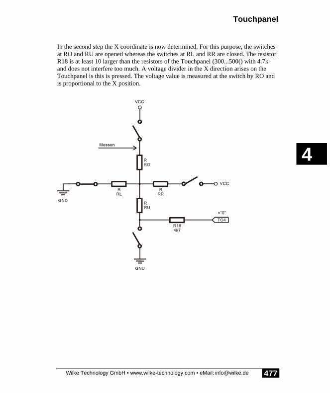
Touchpanel
Wilke Technology GmbH • www.wilke-technology.com • eMail: [email protected]
4
477
In the second step the X coordinate is now determined. For this purpose, the switchesat RO and RU are opened whereas the switches at RL and RR are closed. The resistorR18 is at least 10 larger than the resistors of the Touchpanel (300...500() with 4.7kand does not interfere too much. A voltage divider in the X direction arises on theTouchpanel is this is pressed. The voltage value is measured at the switch by RO andis proportional to the X position.

BASIC-Tiger® Graphic-Toolkit
Wilke Technology GmbH • www.wilke-technology.com • eMail: [email protected]
4
478
In the third and last step the Y position is determined. For this purpose, the switches atRO and RU are closed whereas the switches at RL and RR are opened. The Y positionis now determined by a measurement at RR.
To ensure that three analog inputs of the BASIC-Tiger® are not used, an analogmultiplexer circuit has been integrated on the BASIC-TIGER® Graphic Toolkitwhich enables work with only one analog input.

Touchpanel
Wilke Technology GmbH • www.wilke-technology.com • eMail: [email protected]
4
479
Jumper for Touchpanel
BASIC-Tiger® Graphic-Toolkit
Wilke Technology GmbH • www.wilke-technology.com • eMail: [email protected]
4
480
The following jumpers must be set to use the Touchpanel on the BASIC-TIGER®Graphic Toolkit :
The analog values of the Touchpanel are read in via an analog port. The 3 measuringpoints are switched via an analog switch to its input as required. The switchover iscarried out via an extended output, the 13 jumpers must therefore be set. 2 devicedrivers are available to read in analog values:
• ANALOG1.TDD reads an analog value from a channel when required, i.e.with a GET-instruction.
• ANALOG2.TDD reads in analog values from between one and 4 channelstriggered by TIMERA.TDD.
If the application does not require ANALOG2.TDD, the Touchpanel can becontrolled more simply with ANALOG1.TDD.
There are two further basic possibilities to use the Touchpanel:
• In most applications the panel should be used like a keyboard and the keysand points of contact shown graphically. The application then must have asubroutine which recognizes the keystrokes. An acoustic or visual responseis sensible to show that a keystroke has been recognized.
• Some applications need continuous information as to whether, and if yes,where a contact has taken place. The application then must have a taskwhich permanently provides information about the contact. As a rule, avisual response is carried out on the LCD.
After installation a new Touchpanel type must be calibrated to assign the positions onthe panel to positions on the LCD in the program.

Touchpanel
Wilke Technology GmbH • www.wilke-technology.com • eMail: [email protected]
4
481
There now follow some example programs:
Program
TKB_TST1.TIG The analog measured values of the contact are showndirectly, namely 6 values side by side which are rewritten insequence. As soon as the scan value < 1023, values arise forX and Y. The fluctuations of the measurements and 'wrong'values from the moment of contact or release can be seen.The boundary values of the Touchpanel can be determinedwith this test program.
TKB_DRAW.TIG New results are constantly delivered during contact. Amessage in a FIFO buffer reduces interferences. The detectedposition is made visible by a cursor which is copied into theoriginal picture. For this purpose a copy of the originalpicture is made before copying the cursor.
TKB_KEY1.TIG If a number of results lie within the same range of valueswithin a certain time, this is understood as a keystroke and akey code is passed on. Every contact creates only one code.To create a new keystroke you must release the pressureoccasionally.
TKB_TST2.TIG As TKB_TST1.TIG but uses ANALOG2.TDD. Only resultsfor X and Y are created. The FIFO may not become full,even if the panel is touched. You may have to switch to theRUN mode.
TKB_KEY2.TIG As TKB_KEY1.TIG but uses ANALOG2.TDD. Theapplication must deliver the X and Y-values together withthe analog measured values.

BASIC-Tiger® Graphic-Toolkit
Wilke Technology GmbH • www.wilke-technology.com • eMail: [email protected]
4
482
Touchpanel CursorIn the following example, the analog measurements which arise when the Touchpanelis touched are collected in a FIFO buffer for the purpose of averaging. The depth ofthe buffer can be set by '#define' in the program. Unlike TKB_KEY1.TIG, averagedvalues for the contact position are constantly supplied to the main program via globalvariables.
The main programme displays the cursor as a small 8 x8 graphic in the original LCDdisplay. This takes place in a copy of the original so that this is not destroyed. Ifdesired, this output can also be shifted to the task 'TPanel'.
Program example:
'--------------------------------------------------------------------'Name: TKB_DRAW.TIG'The main program shows touch positions on the LCD'The scanning task can be copied and used in own programs.'Integrated scan values are constantly refreshed'and are globally available.'--------------------------------------------------------------------'Note: connect L71 to reset LCD'--------------------------------------------------------------------user_var_strict 'variables must be declared#include DEFINE_A.INC 'general defines#include UFUNC3.INC 'definitions of user function codes#include LCD_4.INC 'definitions for LCD Typ 4#include GR_TK1.INC 'definitions for Graphic Toolkit
LONG tp_x, tp_y 'global X and Y values of touch panelSTRING Screen$(3840) 'original pixel dataSTRING Scr$(3840) 'copy of pixel data -> insert cursor
'the following 4 values depend on size'and position of the touch panel#define TP_XMIN 106 'min-max values of touch panel area#define TP_XMAX 830#define TP_YMIN 174#define TP_YMAX 840
#define TP_INTEG 32 'integration depth (value=2^n)
'--------------------------------------------------------------------'Main program'Installs device driver and initializes LCD'Shows X and Y values from task TPanel'--------------------------------------------------------------------TASK Main 'begin task MAIN

Touchpanel
Wilke Technology GmbH • www.wilke-technology.com • eMail: [email protected]
4
483
FIFO tpf_x (TP_INTEG) of WORD 'X integration FIFO tpf_y (TP_INTEG) of WORD 'Y integration BYTE i LONG old_tp_x, old_tp_y LONG lcd_x, lcd_y 'cursor X-, Y-Werte on LCD STRING GrCursor$
call Init_LCDpins
install_device #LCD2,"LCD-6963.TDD",0,0,0EEH,4,150,11H install_device #AD1, "ANALOG1.TDD" 'install analog-in device driver '8x8 cursor Graphic GrCursor$ = "<10h><10h><10h><0ffh><10h><10h><10h><0>" put #LCD2, "<1Bh>c<20><0F0h>" 'text cursor off print #LCD2, "<1Bh>A<10><10><0F0h>please touch" run_task TPanel, 20 'start touch panel task
Screen$ = FILL$( "<00H>", 3840 ) 'here: empty screen
tp_x = 0 tp_y = 0 old_tp_x = tp_x old_tp_y = tp_y for i = 0 to 0 step 0 'endless loop if (tp_x <> old_tp_x) or (tp_y <> old_tp_y) then print #LCD2, "<1bh>A<0><0><0F0h>Scanned:";tp_x;";";tp_y;" "; 'touch coord. into screen coord. lcd_x = lin_approx (TP_XMIN, 0, TP_XMAX, 239, tp_x) lcd_y = (LINES-1) - (lin_approx (TP_YMIN, 0, TP_YMAX, 127, tp_y)) print #LCD2, "<1bh>A<0><1><0F0h> LCD:";lcd_x;";";lcd_y;" "; scr$ = screen$ 'save original graphic_copy (Scr$, & 'screen content GrCursor$, & 'cursor COLUMNS, LINES, & 'size destination lcd_x-3, lcd_y-3, & 'dest. position (-3: cursor center) 8, 8, & 'size source to be copied 0, 0, & 'from 7, 7, & 'to = size to be copied 0) 'mode copy put #LCD2, #1, Scr$, 0, 0, 3840 'output to LCD old_tp_x = tp_x old_tp_y = tp_y endif nextEND
'--------------------------------------------------------------------'Integrates touch values'--------------------------------------------------------------------TASK TPanel BYTE i WORD wR0, wX, wY 'scan value, X, Y' X integration' Y integration
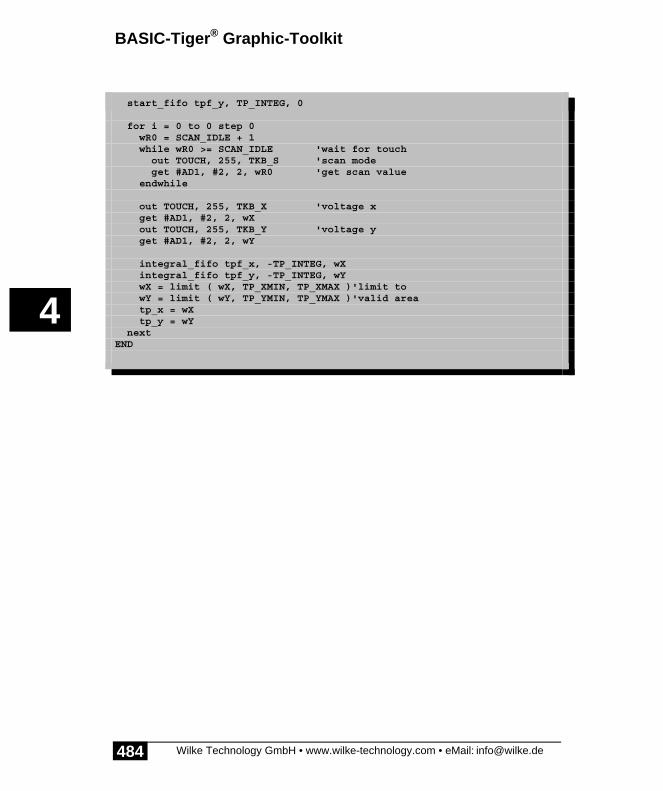
BASIC-Tiger® Graphic-Toolkit
Wilke Technology GmbH • www.wilke-technology.com • eMail: [email protected]
4
484
start_fifo tpf_x, TP_INTEG, 0 'init FIFOs start_fifo tpf_y, TP_INTEG, 0
for i = 0 to 0 step 0 wR0 = SCAN_IDLE + 1 while wR0 >= SCAN_IDLE 'wait for touch out TOUCH, 255, TKB_S 'scan mode get #AD1, #2, 2, wR0 'get scan value endwhile
out TOUCH, 255, TKB_X 'voltage x get #AD1, #2, 2, wX out TOUCH, 255, TKB_Y 'voltage y get #AD1, #2, 2, wY
integral_fifo tpf_x, -TP_INTEG, wX integral_fifo tpf_y, -TP_INTEG, wY wX = limit ( wX, TP_XMIN, TP_XMAX )'limit to wY = limit ( wY, TP_YMIN, TP_YMAX )'valid area tp_x = wX tp_y = wY nextEND

Touchpanel
Wilke Technology GmbH • www.wilke-technology.com • eMail: [email protected]
4
485
Touchpanel as keyboardIn the example program TKB_KEY1.TIG the main task shows a keyboard pattern onthe LCD. In a real application, this is where the screen mask of the application can befound. Incidentally, not all positions need be evaluated as keys. Since this programmeis only a test, the submitted key codes are shown simply in a text form by the maintask. A code is reserved as a character for 'No key pressed' (KEY_INVALID).
In the task TPanel, the Touchpanel is first scanned to detect a contact. This scan modesaves a little current compared to a direct scanning of X or Y values to detect acontact. If a contact is recognized the X and Y values are calculated according to thematrix of the scan codes. A valid keystroke must deliver at least a certain number ofthe same codes. The number can be set by '#define' in the program. The higher thisnumber, the longer the contact must be kept until this becomes a valid keystroke,though also the higher the certainty the no wrong codes will be recognized. The taskwhich is responsible for detecting the keystrokes forwards the key codes to the mainprogramme via global variables. Finally, the system waits until the contact is releasedto prevent an uncontrolled Auto-Repeat function.

BASIC-Tiger® Graphic-Toolkit
Wilke Technology GmbH • www.wilke-technology.com • eMail: [email protected]
4
486
Program example:
'--------------------------------------------------------------------'Name: TKB_KEY1.TIG'with ANALOG1.TDD'The Main program shows touches as key codes on the LCD.
'The scanning task can be copied and used in own programs.'Integrated scan values are constantly refreshed'For a valid key pressure a number of nalog values must be in'certain scope during a given time.'For test purposes the program prints the calculation and'the resulting codes into the key matrix on the screen.'--------------------------------------------------------------------'connect L71 to reset LCD'--------------------------------------------------------------------user_var_strict 'variables must be declared#include DEFINE_A.INC 'general defines#include UFUNC3.INC 'definitions of user function codes#include LCD_4.INC 'definitions for LCD Typ 4#include GR_TK1.INC 'definitions for Graphic Toolkit
'the following 4 values depend on size'and position of the touch panel#define TP_XMIN 106 'min-max values of touch panel area#define TP_XMAX 830#define TP_YMIN 174#define TP_YMAX 840
#define KEY_INVALID 255 'code for 'no-key-pressed'BYTE key 'global for touch keySTRING Screen$(GR_SIZE)DATALABEL keypatt1
'--------------------------------------------------------------------'Main program'Installs device driver and initializes LCD'Displays code of recognized touch keys'--------------------------------------------------------------------TASK Main 'begin task MAINkeypatt1:: data filter "KEY_10X5.BMP", "GRAPHFLT", 0 'keyboard pattern 240 x 128 BYTE ever
call Init_LCDpins
install_device #LCD2,"LCD-6963.TDD",0,0,0EEH,4,150,11H install_device #AD1, "ANALOG1.TDD" 'install analog-in device driver
peek_flash keypatt1, Screen$, 3840 'read picture from FLASH put #LCD2, #1, Screen$,0,0,3840 'show keyboard pattern LCD put #LCD2, "<1Bh>c<20><0F0h>" 'text cursor off print #LCD2, "<1Bh>A<10><10><0F0h>please touch"

Touchpanel
Wilke Technology GmbH • www.wilke-technology.com • eMail: [email protected]
4
487
key = 255 'invalid key run_task TPanel, 20 'start touch panel task
dir_pin 4, 2, 0 'L42 connected with beeper for ever = 0 to 0 step 0 while key = KEY_INVALID 'key invalid, wait for key pressure endwhile ll_iport_out 4, 0 'generate acoustic feed back ll_iport_out 4, 255 'show code of valid key print #LCD2, "<1bh>A<0><4><0F0h>-> global key:";key;" "; key = KEY_INVALID 'once used key becomes invalid nextEND
'--------------------------------------------------------------------'TASK TPanel'Converts scanned analog values into key codes.'The LCD with 240x128 pixel is divided into key areas'TP_KEY_ROWS x TP_KEY_COLUMNS'A touch will be recognized as a key pressure when:' for a number of loops (TP_RECOG_LOOPS) X- and Y-values' out ofthe same area occured'In addition there is a time-out (TP_RECOG_TIMEOUT), after which' a touch must be released before a new key can be pressed.'--------------------------------------------------------------------#define TP_KEY_COLUMNS 10 'number of keys horizontal (X)#define TP_KEY_ROWS 5 'number of keys vertical (Y)#define TP_KEY_XUNIT ((TP_XMAX - TP_XMIN) / TP_KEY_COLUMNS)#define TP_KEY_YUNIT ((TP_YMAX - TP_YMIN) / TP_KEY_ROWS)#define TP_RECOG_LOOPS 10 'loops until key is considered asrecognized
TASK TPanel BYTE i, keytmp WORD wScan WORD wX, wY, old_wX, old_wY WORD tp_recog ''recognized' flag LONG t 'time
key = KEY_INVALID 'begin with invalid key for i = 0 to 0 step 0 'endless loop old_wX = 255 old_wY = 255 wScan = SCAN_IDLE + 1 while wScan >= SCAN_IDLE 'wait for touch out TOUCH, 255, TKB_S 'Scan mode get #AD1, #2, 2, wScan 'get scan value endwhile tp_recog = 0 while tp_recog < TP_RECOG_LOOPS 'recognize loop out TOUCH, 255, TKB_X 'x voltage get #AD1, #2, 2, wX out TOUCH, 255, TKB_Y 'y voltage

BASIC-Tiger® Graphic-Toolkit
Wilke Technology GmbH • www.wilke-technology.com • eMail: [email protected]
4
488
get #AD1, #2, 2, wY if (wX > TP_XMIN) & 'if within valid scope and (wX < TP_XMAX) & and (wY > TP_YMIN) & and (wY < TP_YMAX) then 'then calculate code wX = (wX - TP_XMIN) / TP_KEY_XUNIT wY = (wY - TP_YMIN) / TP_KEY_YUNIT if (wX = old_wX) and (wY = old_wY) then tp_recog = tp_recog + 1 'count occurrence of same code endif old_wX = wX old_wY = wY'if TP_KEY_COLUMNS > TP_KEY_ROWS keytmp = wX * TP_KEY_COLUMNS + wY'if TP_KEY_ROWS > TP_KEY_COLUMS
print #LCD2, "<1bh>A<0><0><0F0h>code calculation:" print #LCD2,"<1bh>A<0><1><0F0h>";keytmp;"=";wX;"*";TP_KEY_COLUMNS;"+";wY;" "; endif endwhile 'recognize loop key = keytmp 'make recognized key global
tp_recog = 0 'now wait for release touch while (wScan < SCAN_IDLE) out TOUCH, 255, TKB_S 'scan mode get #AD1, #2, 2, wScan 'get scan value endwhile nextEND

Touchpanel
Wilke Technology GmbH • www.wilke-technology.com • eMail: [email protected]
4
489
Touchpanel as keyboard with ANALOG2.TDDIn the previous example the keyboard is realised by reading out the analog port withthe measured values from the Touchpanel as required. The free analog inputs can beused for recording or other measurements. If, however, an analog measurement isneeded with the device driver ANALOG2.TDD (together with TIMERA.TDD), thenthis ANALOG2.TDD must deliver both the required measured values for theapplication and the measured values of the Touchpanel.
In this case 2 constellations are conceivable:
• the ANALOG2 is not used simultaneously for measured value recording andthe Touchpanel. In this case the setting of the ANALOG2 can be configuredto match both measurement tasks.
• The ANALOG2 must record measured values and scan the Touchpanel atthe same time. Since the measurement always runs in the background for allrequired channels and there are no restrictions in the choice of channel theamount of programming increases. The following example shows a possibleconstellation and also explains the difficulties.
The main task of the example TKB_KEY2.TIG is representative of any applicationwhich uses ANALOG2 to measure something and at the same time deliver themeasured values of the Touchpanel. Only the measured values of the Touchpanel arecreated here for simplicity's sake. Both the X and the Y values of the Touchpanelcome via an analog input on the BASIC-TIGER® Graphic Toolkit, which is switchedover accordingly. The problem for the task TPanel is now that the task cannot collectthe matching measured values itself after switching the measurement over from X-values and Y-values. Rather, it can only activate the X or Y measurement anddepends on a global variable to obtain the analog measured values from the correctchannel since the actual measurement is controlled by the main task. In this case themeasurement is carried out in a FIFO. To ensure that old X results are not deliveredafter a switchover to Y measurement, the FIFO buffer may never be allowed tobecome full. If the FIFO were full, you would not be able to determine if X or Yvalues were being measured in the measurement when reading out the values. A fullFIFO buffer also causes a delay since old values are read out first.
If the prerequisite is fulfilled that the FIFO buffer is not full, the task TPanel canexpect that the right results will be delivered shortly after the switchover, e.g. from Xto Y measurement. As of this moment, the recognition of keystrokes functions inexactly the same way as TKB_KEY1.TIG.

BASIC-Tiger® Graphic-Toolkit
Wilke Technology GmbH • www.wilke-technology.com • eMail: [email protected]
4
490
To use a Touchpanel in an application with ANALOG2.TDD, the followingprerequisites thus have to be fulfilled:
• the measurement and the operation of the Touchpanel never coincide• or the measurement runs slowly enough that the FIFO buffer does not fill.
If the conditions are not fulfilled, you can consider using a second processor or havinga special device driver developed in the event of large quantities.

Touchpanel
Wilke Technology GmbH • www.wilke-technology.com • eMail: [email protected]
4
491
Program example:
'--------------------------------------------------------------------'Name: TKB_KEY2.TIG'with ANALOG2.TDD'The Main program shows touches as key codes on the LCD.
'The scanning task can be copied and used in own programs.'Integrated scan values are constantly refreshed'For a valid key pressure a number of nalog values must be in'certain scope during a given time.'--------------------------------------------------------------------'Note: connect L71 to reset LCD'--------------------------------------------------------------------user_var_strict 'variables must be declared#include DEFINE_A.INC 'general defines#include UFUNC3.INC 'definitions of user function codes#include LCD_6.INC 'definitions for LCD type 6#include GR_TK1.INC 'definitions for Graphic Toolkit
'the following 4 values depend on size'and position of the touch panel#define TP_XMIN 106 'min-max values of touch panel area#define TP_XMAX 830#define TP_YMIN 174#define TP_YMAX 840
#define KEY_INVALID 255 'code for 'no-key-pressed'BYTE key 'global for touch keySTRING Screen$(GR8_SIZE)STRING Scr$(GR_SIZE)DATALABEL keypatt1
#define TA_RANGE_INIT 3#define TA_DIV_INIT 217#define ANA_PSCAL 6
WORD wTouch, wX, wY, l1, l2
'--------------------------------------------------------------------'Main program'Installs device driver and initializes LCD'Displays code of recognized touch keys'--------------------------------------------------------------------TASK Main 'begin task MAINkeypatt1:: data filter "KEY_8X4.BMP", "GRAPHFLT", 0 'keyboard pattern 240 x 128 BYTE ever FIFO ana ( 1024 ) OF WORD
call Init_LCDpins
install_device #LCD2,"LCD-6963.TDD",0,0,0EEH,LCD_TYPE,150,11H

BASIC-Tiger® Graphic-Toolkit
Wilke Technology GmbH • www.wilke-technology.com • eMail: [email protected]
4
492
install_device #TA, "TIMERA.TDD", TA_RANGE_INIT, TA_DIV_INIT install_device #AD1, "ANALOG2.TDD"
peek_flash keypatt1, Screen$, GR8_SIZE 'read picture from FLASH l1 = len ( Screen$ ) Scr$ = graphic_exp$ ( & 'distribute pixel to bytes screen$, & 'source string LCD_TXT_COL8X8,& 'source horizotal wide in bytes GR6_SIZE, & 'dest. length in pixel LCD_BYT_COL6X8, & 'dest. horizotal wide in byte 6, & 'pixel per byte in target 0) 'shift left in target bytes l2 = len ( Scr$ ) put #LCD2, #1, Scr$,0,0,GR_SIZE 'show keyboard pattern LCD put #LCD2, CURSOR_OFF 'text cursor off print #LCD2, "<1Bh>A<10><10><0F0h>please touch" key = 255 'invalid key wX = 0 wY = 0 run_task TPanel 'start touch panel task put #AD1, #0, #UFCO_AD2_RESO, 10 put #AD1, #0, #UFCO_AD2_SCAN, 1 'no. of channels An2(touchkb) put #AD1, #0, #UFCO_AD2_CHAN, 2 'channel An2(touchkb) put #AD1, #0, #UFCO_AD2_PSCAL, ANA_PSCAL put #AD1, ana 'start analog capture
'comment this line out later run_task Disp 'FIFO should not run full
dir_pin 4, 2, 0 for ever = 0 to 0 step 0 'endless loop while key = KEY_INVALID 'wait for key pressure if len_fifo ( ana ) > 1 then get_fifo ana, wTouch 'get new scan value endif endwhile ll_iport_out 4, 0 ll_iport_out 4, 255 print #LCD2, "<1bh>A<0><8><0F0h>-> global key:";key;" "; key = KEY_INVALID 'once used key becomes invalid nextEND
'--------------------------------------------------------------------'TASK TPanel'Converts scanned analog values into key codes.'The LCD with 240x128 pixel is divided into key areas'TP_KEY_ROWS x TP_KEY_COLUMNS'A touch will be recognized as a key pressure when:' for a number of loops (TP_RECOG_LOOPS) X- and Y-values' out of the same area occured' a touch must be released before a new key can be pressed.'--------------------------------------------------------------------#define TP_KEY_COLUMNS 8 'number of keys horizontal (X)

Touchpanel
Wilke Technology GmbH • www.wilke-technology.com • eMail: [email protected]
4
493
#define TP_KEY_ROWS 4 'number of keys vertical (Y)#define TP_KEY_XUNIT ((TP_XMAX - TP_XMIN) / TP_KEY_COLUMNS)#define TP_KEY_YUNIT ((TP_YMAX - TP_YMIN) / TP_KEY_ROWS)#define TP_RECOG_LOOPS 3 'loops until key is considered asrecognized
TASK TPanel BYTE ever, keytmp WORD wScan WORD wX, wY, old_wX, old_wY WORD tp_recog 'recognize flag LONG t, tt, ttt 'time
key = KEY_INVALID 'begin with invalid key for ever = 0 to 0 step 0 'endless loop old_wX = 0 old_wY = 0 tp_recog = 0 while tp_recog < TP_RECOG_LOOPS 'recognize loop out TOUCH, 255, TKB_X 'get x voltage ttt = 0 tt = ticks() while ttt < 30 ttt = diff_ticks ( tt ) endwhile wX = wTouch
out TOUCH, 255, TKB_Y 'get y voltage ttt = 0 tt = ticks() while ttt < 30 ttt = diff_ticks ( tt ) endwhile wY = wTouch
if (wX > TP_XMIN) and & 'if within valid scope (wX < TP_XMAX) and & (wY > TP_YMIN) and & (wY < TP_YMAX) then 'then calculate code wX = (wX - TP_XMIN) / TP_KEY_XUNIT wY = (wY - TP_YMIN) / TP_KEY_YUNIT if (wX = old_wX) and (wY = old_wY) then tp_recog = tp_recog + 1 'count occurrence of same code endif old_wX = wX old_wY = wY'if TP_KEY_COLUMNS > TP_KEY_ROWS keytmp = wX * TP_KEY_COLUMNS + wY'if TP_KEY_ROWS > TP_KEY_COLUMS
' 3 test prints print #LCD2, "<1bh>A<0><0><0F0h>code calculation:" print #LCD2,"<1bh>A<0><1><0F0h>";keytmp;"=";wX;"*";TP_KEY_COLUMNS;"+";wY;" ";

BASIC-Tiger® Graphic-Toolkit
Wilke Technology GmbH • www.wilke-technology.com • eMail: [email protected]
4
494
print #LCD2, "<1bh>A<0><2><0F0h>";tp_recog;" "; endif endwhile 'recognize loop key = keytmp 'make recognized key global
tp_recog = 0 'now wait for release touch out TOUCH, 255, TKB_S 'Scan mode while wTouch < SCAN_IDLE'one more test print print #LCD2, "<1bh>A<0><4><0F0h>";"wTouch=";wTouch;" "; endwhile
nextEND
'--------------------------------------------------------------------'for test purpose: displays fill level of FIFO'--------------------------------------------------------------------Task Disp BYTE i
for i = 0 to 0 step 0 'endless loop print #LCD2, "<1Bh>A<0><5><0F0h>len of fifo:";len_fifo ( ana );""; wait_duration 200 'give time for graphic output nextEND
Touchpanel
Wilke Technology GmbH • www.wilke-technology.com • eMail: [email protected]
4
495
Touchpanel as complete keyboardIn this example the Touchpanel keyboard is almost complete: it has all letters andnumbers as well as space bar, enter (Return), delete key (del) and even a shift key totoggle between large and small letters.
On the small LCD with 240 X 128 pixels probably only small fingers will be able tohit the correct key immediately. An even finer partitioning with a good hit rate ishardly possible.
The programme has a code conversion table to convert the scan codes to the rightcharacters. The function CONVERT$ does this in a line. The keyboard itself is not anintegrated bitmap but is created by the program. For this purpose the letters arewritten as symbols on the keys on the text screen and the 'Keys' are generated as blackrectangles in the graphic area with GRAPHIC_COPY.
The task Main only calls the subroutine to input 'get_string' and deletes the input lineafter an input (conclusion with Return). 'Get_string‘ enables you to delete individualcharacters and takes into account the conclusion of the input. 'Get_key‘ receives thescan code from the task 'TPanel' and converts this into the character codes dependingon the use of large or small letters. 'Get_key‘ hereby takes into account the Shiftfunction, which changes the keyboard lettering .

BASIC-Tiger® Graphic-Toolkit
Wilke Technology GmbH • www.wilke-technology.com • eMail: [email protected]
4
496
Program example:
'--------------------------------------------------------------------'Name: TKB_KEY3.TIG'with ANALOG1.TDD'The Main program shows a complete keyboard with touch keys.'uses function INDEX_2D'--------------------------------------------------------------------'connect L71 to reset LCD'--------------------------------------------------------------------user_var_strict 'variables must be declared#include DEFINE_A.INC 'general defines#include UFUNC3.INC 'definitions of user function codes#include LCD_4.INC 'definitions for LCD Typ 4#include GR_TK1.INC 'definitions for Graphic Toolkit
'the following 4 values depend on size'and position of the touch panel#define TP_XMIN 95 'in-max values of touch panel area#define TP_XMAX 750#define TP_YMIN 140#define TP_YMAX 650
STRING screen$(GR8_SIZE)STRING mnuscr$(GR8_SIZE)STRING tmpscr$(GR_SIZE)STRING black$(GR_SIZE)
#define KEY_INVALID 255 'code for 'no-key-pressed'BYTE key 'global for touch keyBYTE shiftedSTRING inp$(40)LONG cx, cy 'cursor starting positionLONG x 'cursor relative x-position
#define _CR_ "<0dh>" 'some characters for get_string#define _BS_ "<08h>"
STRING kb_lower$(240) 'keyboard printSTRING kb_upper$(240)STRING conv_lower$(128) 'scan code conversion tablesSTRING conv_upper$(128)
'--------------------------------------------------------------------'Main program'Installs device driver and initializes LCD'--------------------------------------------------------------------TASK Main 'begin task MAIN BYTE ever STRING k$(1)
call Init_LCDpins install_device #LCD2,"LCD-6963.TDD",0,0,0EEH,LCD_TYPE,150,11H

Touchpanel
Wilke Technology GmbH • www.wilke-technology.com • eMail: [email protected]
4
497
install_device #AD1, "ANALOG1.TDD" 'install analog-in device driver dir_pin 4, 2, 0 'L42 connected with beeper
call init_vars 'init some variables put #LCD2, CURSOR_OFF 'text cursor off put #LCD2, MODE_XOR 'LCD mode put #LCD2, TEXT_ON put #LCD2, GRAPHIC_ON key = 255 'invalid key shifted = 255 call gen_kb_text 'keyboard print call gen_kb_graphic 'keyboard graphic run_task TPanel, 20 'start touch panel task
for ever = 0 to 0 step 0 'endless loop call get_string ( & 0, 0, & 'field position 40 ) 'field len print #LCD2, "<1bh>A<0><3><0f0h>entered..."; wait_duration 2000 'after 2 seconds erase 1st line print #LCD2, "<1bh>A<0><3><0f0h> "; print #LCD2, & "<1bh>A<0><0><0f0h> "; next '' new inputEND
'--------------------------------------------------------------------
'return string in global 'inp$''get string from input device 'i_devno' (here: subroutine 'get_key')'and echos to output device with number 'o_devno''on RET the subroutine ends'--------------------------------------------------------------------SUB get_string ( & LONG cxx, cyy, & 'field position slen ) 'field len
BYTE i, i_devno, o_devno STRING c$(1)
o_devno = LCD2 cx = cxx cy = cyy
put #o_devno, CURSOR_ON8 'cursor 1 pixel line, blink
inp$ = fill$ ( " ", slen ) print #LCD2, "<1bh>A"; chr$(cx) ; chr$(cy) ;"<0f0h>"; x = 0 inp$ = ""
next_char1:

BASIC-Tiger® Graphic-Toolkit
Wilke Technology GmbH • www.wilke-technology.com • eMail: [email protected]
4
498
call get_key ( c$ ) if c$ <> "" then switch c$ case _CR_: 'on RET goto end_get_string 'RET ends input '---------------------------------- case _BS_: 'delete a char if x > 0 then 'only if input there x = x - 1 inp$ = left$ ( inp$, len(inp$)-1 ) print #o_devno, "<1bh>A"; chr$(cx+x) ; chr$(cy) ;"<0f0h>";" "; print #o_devno, "<1bh>A"; chr$(cx+x) ; chr$(cy) ;"<0f0h>"; endif '---------------------------------- default: if x < slen then 'as long as not max. length x = x + 1 'count char inp$ = inp$ + c$ 'collect it print #o_devno, c$; endif endswitch endif goto next_char1
end_get_string: print #o_devno, CURSOR_OFFEND
'--------------------------------------------------------------------'SUB get_key'--------------------------------------------------------------------SUB get_key ( var k$ ) STRING tmp$(1)
new_key: while key = KEY_INVALID 'key invalid, wait for key pressure endwhile tmp$ = chr$ ( key ) if shifted = 0 then tmp$ = convert$ ( tmp$, conv_upper$ ) 'code of key else tmp$ = convert$ ( tmp$, conv_lower$ ) 'code of key endif if tmp$ = "<00>" then goto new_key key = KEY_INVALID 'once used key becomes invalid endif if tmp$ = "<0ffh>" then shifted = bitnot ( shifted ) call gen_kb_text ll_iport_out 4, 0 'generate acoustic feed back ll_iport_out 4, 255 key = KEY_INVALID 'once used key becomes invalid print #LCD2, "<1bh>A"; chr$(cx+x) ; chr$(cy) ;"<0f0h>";

Touchpanel
Wilke Technology GmbH • www.wilke-technology.com • eMail: [email protected]
4
499
goto new_key endif k$ = tmp$ ll_iport_out 4, 0 'generate acoustic feed back ll_iport_out 4, 255 key = KEY_INVALID 'once used key becomes invalidEND
'--------------------------------------------------------------------'TASK TPanel'Converts scanned analog values into key codes.'The LCD with 240x128 pixel is divided into key areas'TP_KEY_ROWS x TP_KEY_COLUMNS'A touch will be recognized as a key pressure when:' for a number of loops (TP_RECOG_LOOPS) X- and Y-values' out ofthe same area occured'In addition there is a time-out (TP_RECOG_TIMEOUT), after which' a touch must be released before a new key can be pressed.'--------------------------------------------------------------------#define TP_KEY_COLUMNS 10 'number of keys horizontal (X)#define TP_KEY_ROWS 8 'number of keys vertical (Y)#define TP_KEY_XUNIT ((TP_XMAX - TP_XMIN) / TP_KEY_COLUMNS)#define TP_KEY_YUNIT ((TP_YMAX - TP_YMIN) / TP_KEY_ROWS)#define TP_RECOG_LOOPS 10 'loops until key is considered asrecognized
STRING fields$(400) '44 fields a 2 WORD ccord.=>352 Bytes
TASK TPanel BYTE ever, c, r, keytmp, keyold WORD wScan, pos, pos0 WORD wX, wY, old_wX, old_wY WORD tp_recog ''recognized' flag LONG t 'time
fields$ = "" 'init fields$ pos = 0 r = 0 'keyboard row 0 (lowest) for c = 0 to 3 '4 keys shift, space, del ret 'set 1st coord. pair wX = TP_XMIN + (c * (TP_XMAX - TP_XMIN) / 4) 'here 4 columns fields$ = ntos$ ( fields$, pos, 2, wX ) wY = TP_YMIN fields$ = ntos$ ( fields$, pos+2, 2, wY ) pos = pos + 4 'set 2nd coord. pair wX = TP_XMIN + ((c+1) * (TP_XMAX - TP_XMIN) / 4) fields$ = ntos$ ( fields$, pos, 2, wX ) wY = TP_YMIN + ((r+1) * TP_KEY_YUNIT) fields$ = ntos$ ( fields$, pos+2, 2, wY ) pos = pos + 4 next pos0 = pos 'position in string for coord.
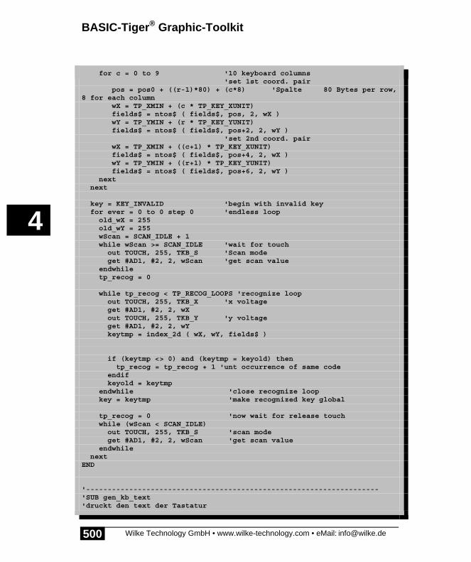
BASIC-Tiger® Graphic-Toolkit
Wilke Technology GmbH • www.wilke-technology.com • eMail: [email protected]
4
500
for r = 1 to 4 '4 upper keyboard rows for c = 0 to 9 '10 keyboard columns 'set 1st coord. pair pos = pos0 + ((r-1)*80) + (c*8) 'Spalte 80 Bytes per row,8 for each column wX = TP_XMIN + (c * TP_KEY_XUNIT) fields$ = ntos$ ( fields$, pos, 2, wX ) wY = TP_YMIN + (r * TP_KEY_YUNIT) fields$ = ntos$ ( fields$, pos+2, 2, wY ) 'set 2nd coord. pair wX = TP_XMIN + ((c+1) * TP_KEY_XUNIT) fields$ = ntos$ ( fields$, pos+4, 2, wX ) wY = TP_YMIN + ((r+1) * TP_KEY_YUNIT) fields$ = ntos$ ( fields$, pos+6, 2, wY ) next next
key = KEY_INVALID 'begin with invalid key for ever = 0 to 0 step 0 'endless loop old_wX = 255 old_wY = 255 wScan = SCAN_IDLE + 1 while wScan >= SCAN_IDLE 'wait for touch out TOUCH, 255, TKB_S 'Scan mode get #AD1, #2, 2, wScan 'get scan value endwhile tp_recog = 0
while tp_recog < TP_RECOG_LOOPS 'recognize loop out TOUCH, 255, TKB_X 'x voltage get #AD1, #2, 2, wX out TOUCH, 255, TKB_Y 'y voltage get #AD1, #2, 2, wY keytmp = index_2d ( wX, wY, fields$ )
if (keytmp <> 0) and (keytmp = keyold) then tp_recog = tp_recog + 1 'unt occurrence of same code endif keyold = keytmp endwhile 'close recognize loop key = keytmp 'make recognized key global
tp_recog = 0 'now wait for release touch while (wScan < SCAN_IDLE) out TOUCH, 255, TKB_S 'scan mode get #AD1, #2, 2, wScan 'get scan value endwhile nextEND
'--------------------------------------------------------------------'SUB gen_kb_text'druckt den text der Tastatur

Touchpanel
Wilke Technology GmbH • www.wilke-technology.com • eMail: [email protected]
4
501
'--------------------------------------------------------------------SUB gen_kb_text BYTE i
if shifted = 0 then ' capitals print #LCD2, "<1bh>A<0><06><0f0h>";kb_upper$; else print #LCD2, "<1bh>A<0><06><0f0h>";kb_lower$; endifEND
'--------------------------------------------------------------------'SUB gen_kb_graphic'generates the black buttons in graphic'--------------------------------------------------------------------SUB gen_kb_graphic BYTE i, button_xsize, button_ysize, buttonx, buttony
button_xsize = 2 * FONT_X + 2 button_ysize = 2 * FONT_Y - 2
for i = 0 to 9 buttonx = FONT_X - 4 + (i*(button_xsize+6)) buttony = -3 + (6 * FONT_Y) graphic_copy ( & 'white text on black background mnuscr$, & 'destination black$, & 'source COLUMNS, LINES, & 'dest. size buttonx, buttony, & 'position in destination COLUMNS, LINES, & 'source size 0, 0, & 'source position button_xsize, button_ysize, &' copied size 0) 'mode copy next
for i = 0 to 9 buttonx = FONT_X - 4 + (i*(button_xsize+6)) buttony = -3 + (8 * FONT_Y) graphic_copy ( & 'white text on black background mnuscr$, & 'destination black$, & 'source COLUMNS, LINES, & 'dest. size buttonx, buttony, & 'position in destination COLUMNS, LINES, & 'source size 0, 0, & 'source position button_xsize, button_ysize, &' copied size 0) 'mode copy next
for i = 0 to 9 buttonx = FONT_X - 4 + (i*(button_xsize+6)) buttony = -3 + (10 * FONT_Y) graphic_copy ( & 'white text on black background mnuscr$, & 'destination

BASIC-Tiger® Graphic-Toolkit
Wilke Technology GmbH • www.wilke-technology.com • eMail: [email protected]
4
502
black$, & 'source COLUMNS, LINES, & 'dest. size buttonx, buttony, & 'position in destination COLUMNS, LINES, & 'source size 0, 0, & 'source position button_xsize, button_ysize, &' copied size 0) 'mode copy next
for i = 0 to 9 buttonx = FONT_X - 4 + (i*(button_xsize+6)) buttony = -3 + (12 * FONT_Y) graphic_copy ( & 'white text on black background mnuscr$, & 'destination black$, & 'source COLUMNS, LINES, & 'dest. size buttonx, buttony, & 'position in destination COLUMNS, LINES, & 'source size 0, 0, & 'source position button_xsize, button_ysize, &' copied size 0) 'mode copy next
button_xsize = 5 * FONT_X + 10 for i = 0 to 3 buttonx = FONT_X - 4 + (i*(button_xsize+10)) buttony = -3 + (14 * FONT_Y) graphic_copy ( & 'white text on black background mnuscr$, & 'destination black$, & 'source COLUMNS, LINES, & 'dest. size buttonx, buttony, & 'position in destination COLUMNS, LINES, & 'source size 0, 0, & 'source position button_xsize, button_ysize, &'copied size 0) 'mode copy next
if LCD_MODE = LCD_MODE6X8 then 'if LCD type 6 tmpscr$ = graphic_exp$ ( & 'distribute pixel to bytes mnuscr$, & 'source string LCD_TXT_COL8X8,& 'source horizotal wide in bytes GR6_SIZE, & 'dest. length in pixel LCD_BYT_COL6X8, & 'dest. horizotal wide in byte 6, & 'pixel per byte in target 0) 'shift left in target bytes else tmpscr$ = let$ ( mnuscr$ ) endif put #LCD2, #1, tmpscr$, 0, 0, GR_SIZE 'show graphic on LCDEND
'--------------------------------------------------------------------'SUB init_vars

Touchpanel
Wilke Technology GmbH • www.wilke-technology.com • eMail: [email protected]
4
503
'--------------------------------------------------------------------SUB init_vars screen$ = fill$ ( "<0>", GR8_SIZE ) 'init all strings mnuscr$ = fill$ ( "<0>", GR8_SIZE ) black$ = fill$ ( "<255>", GR8_SIZE ) tmpscr$ = fill$ ( "<0>", GR_SIZE )
conv_upper$ = " & 'conversion from scan value to key code00 FF 20 08 0D 59 58 43 56 42 4E 4D 3B 3A 5F 41 & ' 00...0F53 44 46 47 48 4A 4B 4C 3F 51 57 45 52 54 5A 55 & ' 10...1F49 4F 50 3D 21 22 23 24 25 26 2F 2B 2A 00 00 00 & ' 20...2F00 00 00 00 00 00 00 00 00 00 00 00 00 00 00 00 & ' 30...3F00 00 00 00 00 00 00 00 00 00 00 00 00 00 00 00 & ' 40...4F00 00 00 00 00 00 00 00 00 00 00 00 00 00 00 00 & ' 50...5F00 00 00 00 00 00 00 00 00 00 00 00 00 00 00 00 & ' 60...6F00 00 00 00 00 00 00 00 00 00 00 00 00 00 00 00 & ' 70...7F"%
conv_lower$ = " & 'conversion from scan value to key code00 FF 20 08 0D 79 78 63 76 62 6E 6D 2C 2E 2D 61 & ' 00...0F73 64 66 67 68 6A 6B 6C 3F 71 77 65 72 74 7A 75 & ' 10...1F69 6F 70 30 31 32 33 34 35 36 37 38 39 00 00 00 & ' 20...2F00 00 00 00 00 00 00 00 00 00 00 00 00 00 00 00 & ' 30...3F00 00 00 00 00 00 00 00 00 00 00 00 00 00 00 00 & ' 40...4F00 00 00 00 00 00 00 00 00 00 00 00 00 00 00 00 & ' 50...5F00 00 00 00 00 00 00 00 00 00 00 00 00 00 00 00 & ' 60...6F00 00 00 00 00 00 00 00 00 00 00 00 00 00 00 00 & ' 70...7F"%
kb_lower$ = "& 'keyboard layout lower 0 1 2 3 4 5 6 7 8 9<13><10><10>& q w e r t z u i o p<13><10><10>& a s d f g h j k l ?<13><10><10>& y x c v b n m , . -<13><10><10>& shift space del ret"
kb_upper$ = "& 'keyboard layout upper = ! <22h> # $ <25h> <26h> <2fh> + *<13><10><10>& Q W E R T Z U I O P<13><10><10>& A S D F G H J K L ?<13><10><10>& Y X C V B N M ; : _<13><10><10>& shift space del ret"
END

BASIC-Tiger® Graphic-Toolkit
Wilke Technology GmbH • www.wilke-technology.com • eMail: [email protected]
4
504

Wilke Technology GmbH • www.wilke-technology.com • eMail: [email protected] 505
About this manual 1Device driver 2Applications 3BASIC Tiger® Graphic Toolkit 4Frequently asked questions 5Index 6Appendix 7

Frequently asked questions
Wilke Technology GmbH • www.wilke-technology.com • eMail: [email protected]
5
507
5 Frequently asked questionsHow do I use the instruction PWM?
In BASIC Tiger®, a corresponding device driver is used in place of a special BASICinstruction. The choice of the device drivers, for example, determines whether theprogram addresses the internal PWM-pins of the BASIC Tiger® or external PWM-/DA-components. Once the corresponding driver has been included, the desiredvalue, between 0 and 255, is simply output at the output channel of the PWMdriver,"PWM1.TDD". Since BASIC Tiger® is a Multitasking-System, once a value isset, it remains at the PWM output until explicitly overwritten by a new value.BASIC Tiger® does not stop at the PWM output, nor does the PWM value end whenthe program execution reaches the next BASIC instruction.
Can I program the BASIC Tiger® module in a machine language too?
No. The only available level is programming in Tiger BASIC®. Tiger BASIC®
generates very fast program code to meet the user's wishes for higher speeds. Youshould choose a Tiger module of the corresponding performance class depending onthe throughput or response behavior requirements.
The absence of a lower language level has the advantage that Tiger BASIC®
programs are easily portable between various module types. Moreover, it ispractically impossible to accidentally cause a crash in the runtime system, whichmakes an important contribution to the high reliability of BASIC Tiger®.
How much current can the I/O-Pins of the module provide or draw?
If all pins are loaded equally you should not greatly exceed 1mA per pin (<1.5mA). Ifa maximum of 8 pins are loaded, these can provide or draw up to 3.5mA.
What do I do with pin 1 on module ANN-X/X?
Connect to VCC or leave free.
How do I address the extended outputs on the Plug & Play Lab?
In exactly the same way as the internal ports, simply using other addresses. Thepossible address range for the extended ports is between: 10H....FFH (16...255). The8 ePort outputs on the Plug & Play Lab are in the address range: 10H...17H(16...23). All 8 x 8 output bits of these ePorts are represented by an LED above the

Frequently asked questions
Wilke Technology GmbH • www.wilke-technology.com • eMail: [email protected]
5
508
keyboard. One example of a command to output a byte at the lowest ePort (10H)could thus be: OUT 10H,0FFH,data_byte.
I have set port-pins with the OUT instruction, for example, but nothing happens at thepins. Why?
The ports of a BASIC Tiger® module can in principle be used for a wide variety ofpurposes. Instructions such as IN and OUT can be used to directly access the ports ofa module - provided these pins are not already otherwise occupied. The mechanismswhich also use the ports are: device driver as well as the ePort system for extensionup to 1920 additional digital inputs or outputs.
If, for example, a device driver such as "LCD1.TDD" is using a Port-Pin, the drivermay block this pin for all other accesses (with IN or OUT) if necessary. Although youare allowed to execute a task at such a port with OUT, the reserved pins remaincompletely unchanged. This is a protective mechanism to ensure the correct functionof the connected peripheral devices and it simplifies programming since no explicitmeasures have to be taken to leave such pins unchanged
In the Plug & Play Lab the pins L60→L67 and L30→L37 are assigned to controlextended ports and thus cannot be addressed with IN or OUT.
You can dispense with the activity of extended ports by using the compiler instructionUSER_EPORT ACT, NOACTIVE (See Device Driver Manual). These pins can thenbe addressed as normal.
Are the device drivers re-entrant?
Device drivers like subroutines can be used, in principle, simultaneously by a randomnumber of tasks. Unlike subroutines, however, every device driver has an input oroutput device. As long as the corresponding peripheral device is being sensiblyaddressed, you will receive a sensible result.
As an example: Various tasks can make their outputs simultaneously on the LCDpanel of the Plug & Play Lab. You should simply pay attention to the position of theLCD cursor and the buffer situation. One possibility here is to have every task whichwants to output something on LCD execute an absolute cursor positioning at thebeginning of every PRINT instruction and then the corresponding output. Since asingle BASIC instruction will never be interrupted by the Multitasking-System, aPRINT instruction will always be completely executed. Thus, the cursor positioningand subsequent output will not be disturbed.
You should also take care to ensure that the output buffer of the LCD is not constantlyfull - which would be impractical. A predominantly full output buffer could cause the

Frequently asked questions
Wilke Technology GmbH • www.wilke-technology.com • eMail: [email protected]
5
509
following effect: Task X writes in the output buffer until this is full. Shortly afterwardsTask Y also wishes to write in this buffer, though is unable to do so because the bufferis still full. Task Y thus "waits". A little while later, when Task X again executes aPRINT on this device, the buffer may have just enough space for further data, so thatit is again full. Task X has thus again sent data. Task Y will once again find a fullbuffer when it tries to write its data .... Interferences from a random character arise.
Can RAM or Flash memories be extended via the bus?
No, BASIC Tiger® modules are autonomous computer modules, not CPU blocks.BASIC Tigers® have no external bus for memory, a corresponding module with thedesired memory size should be selected and used. This ensures the high reliability andgood EMC values.
In certain applications, however, it may prove practical to connect additional memory(RAM, ROM, disks ...) e.g. to accommodate very large data volumes or to usemovable memory. This can be achieved either via a separate device driver, I²C-bus orvia corresponding BASIC subroutines.
Can PEEK and POKE be used for a direct access to the hardware?
The instructions PEEK and POKE enable access to free areas of the FLASH memory.This is usually used to store data that must be retained after a power-down andpower-up. Examples of such data include calibration tables, registered measuredvalues, databases, operating time counters etc. Tiger BASIC® provides theprogrammer with those FLASH memory areas that are not occupied by BASICprograms for this purpose.
In accordance with the characteristics of the FLASH memory, areas are onlyavailable in complete blocks. Tiger BASIC® automatically ensures that a BASICprogram can never accidentally erase itself. The number and size of the free sectorsdepends on the module type and program size. The FLASH memory is always erasedin entire sectors (Content = FFh). Further information on using the FLASH can befound in the Hardware Manual.
Frequently asked questions
Wilke Technology GmbH • www.wilke-technology.com • eMail: [email protected]
5
510
A task stops after a while for no apparent reason. Why?
The stack probably overflows from time to time. Make sure that the task and thesubroutines used by the task contain no endless recursive calls. The stack can then beenlarged with the compiler instruction USER_STACK_SIZE (see ProgrammingManual).
Why are the DIP switches always initially read incorrectly after a power up or reset?
The result of the last scan is always read. You have to wait for a scan that is carriedout just after the reset, i.e. around 20 msec.
Certain numbers are excluded from the USING format, whereas others are formattedcorrectly. Why?
You have probably specified "Zero" as a fill sign. You may not use numbers as fillsigns, which includes the ‘0’ (zero). You should increase the minimum number ofdigits shown.

Frequently asked questions
Wilke Technology GmbH • www.wilke-technology.com • eMail: [email protected]
5
511
Tips and assistanceShould you encounter difficulties with a Tiger BASIC® program:
• Try to reduce the problem to the simplest possible example. This shouldresult in a maximum of one page, usually only a few lines.
• Make a note of how much RAM and Flash the BASIC Tiger® module thatyou are using has. Use the command Tiger status in the menu View.
• Which Compiler version are you using (see About... in the Help menu).• Which version are the involved device drivers (see Device driver list ... in
the View menu).• Describe the error as precisely as possible.• In what context does the problem occur?• Does it always occur at the same place or only occasionally?• List all of your communication numbers such as fax number, telephone
number, etc. in your inquiry so that we can reach you as quickly as possible.
BASIC Tiger®-Service-Hotline:+49 / 241 / 15 15 99
Wilke Technology GmbHKrefelder Str. 147Postfach 1727
D-52070 Aachen / Germany
Tel: +49 / 241 / 918900Fax: +49 / 241 / 9189044eMail: [email protected]

Frequently asked questions
Wilke Technology GmbH • www.wilke-technology.com • eMail: [email protected]
5
512
In the North America contact:
Kg Systems, Inc.#3 Dorine Industrial ParkMerry LaneEast Hanover, NJ 07936USA
Tel: 973-515-4664Fax: 973-515-1033eMail: [email protected]
http://www.industrialcontroller.com

Wilke Technology GmbH • www.wilke-technology.com • eMail: [email protected] 513
About this manual 1Device driver 2Applications 3BASIC Tiger® Graphic Toolkit 4Frequently asked questions 5Index 6Appendix 7

Index
Wilke Technology GmbH • www.wilke-technology.com • eMail: [email protected]
6
515
6 Index
—A—A/D-Inputs.................................... 31
EP11 with ANALOG3.TDD ...... 45Alarm-Beep................................ 109Analog 12-Bit ............................... 42ANALOG2 device driver............... 33Analog3 Device Driver ................. 45ANSI Control Sequences ........... 525ASCII codes............................... 521Audio output............................... 101Auto-repeat .................................. 94
—B—Baudot-Code.............................. 523Beep .......................................... 105Buffer fill level, inquire.................. 20Buffer, delete content................... 23Buffer, inquire free space............. 21Buzzer........................................ 101
—C—CAN
Access-Code and -Mask........ 266Arbitration-Lost-Error ............. 262Bustiming ............................... 257Device driver .......................... 247Dual-Filter .............................. 279ECC error register.................. 263Error-Register ........................ 260Extended Frame-Format........ 253Introduction ............................ 303Receive CAN messages ........ 291Receive filter with Code and Mask
........................................... 266RXERR receiver error counter265Sending CAN messages........ 287Standard-Frame-Format ........ 251
TXERR-Tx error counter ........ 265Using of buffer space ............. 297
Cursor .................................. 75, 126
—D—Delete buffer content.................... 23Designation R+C........................ 531Device driver ............................ 3, 15device driver functions ................. 19DIP-switch .................................... 96
—E—EBCDIC codes ........................... 522Echo on LCD1.............................. 89Encoder...................................... 158Eos ....................................... 56, 118Esc ....................................... 56, 118ESC a........................................... 94ESC B ........................................ 105ESC c ........................................... 75ESC C ........................................ 103ESC Commands .......................... 56ESC D .......................................... 96ESC k ........................................... 99ESC K ........................................ 107ESC r............................................ 91ESC z ........................................... 93ESC-A .................................. 65, 120ESC-c......................................... 126ESC-Commands ........................ 118ESC-L........................... 69, 123, 125ESC-M.......................................... 73ESC-R .......................................... 71ESC-S .......................................... 67
—F—Frequency meter ........................ 165Function codes............................... 4

Index
Wilke Technology GmbH • www.wilke-technology.com • eMail: [email protected]
6
516
Functions ..................................... 11
—G—Graphic output ........................... 132Gray Code ................................. 524
—H—Handshake, serial ...................... 209
—I—INPUT .......................................... 89Inquire free space in a buffer ....... 21Inquire level of a buffer ................ 20
—K—Key attributes............................... 94Key click..................................... 107Key codes .................................... 93Keyboard ............................. 87, 430
Auto-Repeat............................. 91keyboard - software ..................... 87Keyboard customization,
Plug & Play Lab ..................... 382keyboard scan addresses ............ 99
—L—LCD disable ................................. 61LCD1 - keyboard.......................... 87LCD1 - special parameters .......... 58LCD6963 Special character ....... 128LCD-display and keyboard........... 55LC-display.................................... 61LC-Display ................................. 114LC-display type ............................ 60
—M—Menu............................................ 73MF-II-PC-keyboard .................... 137Multitasking.................................. 10
—P—Parallel in ................................... 147Parallel printer............................ 143
PC-Keyboard.............................. 137Position cursor ..................... 65, 120Pulse counting............................ 153pulse I/O..................................... 151Pulse length measuring...... 169, 173pulse length, request buffer fill level
............................................... 171Pulse ouput ................................ 177Pulse output ............................... 181PWM .......................................... 185PWM2 device driver ................... 189
—R—RES1.......................................... 377
—S—sample rate .................................. 43scan addresses ............................ 99Secondary addresses .................... 4Serial interface
direct into strings .................... 233up to 614200baud .................. 233
Serial interface by software........ 223Serial interfaces ......................... 201serial parameters ....................... 206SET1 .......................................... 375sound pin LCD1 ........................... 60Sound, deactivate ...................... 103special character set .... 69, 123, 125Special character set.................... 67
—T—Tiger-Shortcuts........................... 529Time-base timer ......................... 365TIMERA...................................... 365TMEM......................................... 353Touchpanel as keyboard............ 485
—U—UFC.............................................. 19UFCO_IBU_ERASE..................... 23UFCO_IBU_FILL.......................... 20UFCO_IBU_FREE ....................... 21UFCO_OBU_ERASE ................... 23

Index
Wilke Technology GmbH • www.wilke-technology.com • eMail: [email protected]
6
517
UFCO_OBU_FILL........................ 20UFCO_OBU_FREE ..................... 21USER-FUNCTION-CODE............ 19
—V—Version....................................... 385
Version, inquire ............................ 25
—W—Windows-Shortcuts .................... 527

Wilke Technology GmbH • www.wilke-technology.com • eMail: [email protected] 519
About this manual 1Device driver 2Applications 3BASIC Tiger® Graphic Toolkit 4Frequently asked questions 5Index 6Appendix 7

Appendix - ASCII codes
Wilke Technology GmbH • www.wilke-technology.com • eMail: [email protected]
7
521
7 Appendix
ASCII codesASCII, pronounced ask-ee, is an acronym for ‚American Standard Code forInformation Interchange’. The ASCII code is probably the most used code forrepresenting characters, numbers, and some special characters and control characters.The code is used on The PC, Macintosh, and in the internet.
CHAR HEX DEC CHAR HEX DEC CHAR HEX DEC CHAR HEX DEC
NUL 00 000 SP 20 032 @ 40 064 60 096
SOH 01 001 ! 21 033 A 41 065 a 61 097
STX 02 002 " 22 034 B 42 066 b 62 098
ETX 03 003 # 23 035 C 43 067 c 63 099
EOT 04 004 $ 24 036 D 44 068 d 64 100
ENQ 05 005 % 25 037 E 45 069 e 65 101
ACK 06 006 & 26 038 F 46 070 f 66 102
BEL 07 007 ' 27 039 G 47 071 g 67 103
BS 08 008 ( 28 040 H 48 072 h 68 104
HT 09 009 ) 29 041 I 49 073 i 69 105
LF 0A 010 * 2A 042 J 4A 074 j 6A 106
VT 0B 011 + 2B 043 K 4B 075 k 6B 107
FF 0C 012 , 2C 044 L 4C 076 l 6C 108
CR 0D 013 - 2D 045 M 4D 077 m 6D 109
SO 0E 014 . 2E 046 N 4E 078 n 6E 110
SI 0F 015 / 2F 047 O 4F 079 o 6F 111
DLE 10 016 0 30 048 P 50 080 p 70 112
D1 11 017 1 31 049 Q 51 081 q 71 113
D2 12 018 2 32 050 R 52 082 r 72 114
D3 13 019 3 33 051 S 53 083 s 73 115
D4 14 020 4 34 052 T 54 084 t 74 116
NAK 15 021 5 35 053 U 55 085 u 75 117
SYN 16 022 6 36 054 V 56 086 v 76 118
ETB 17 023 7 37 055 W 57 087 w 77 119
CAN 18 024 8 38 056 X 58 088 x 78 120
EM 09 025 9 39 057 Y 59 089 y 79 121
SUB 1A 026 : 3A 058 Z 5A 090 z 7A 122
ESC 1B 027 ; 3B 059 [ 5B 091 { 7B 123
FS 1C 028 < 3C 060 \ 5C 092 | 7C 124
GS 1D 029 = 3D 061 ] 5D 093 } 7D 125
RS 1E 030 > 3E 062 ^ 5E 094 ~ 7E 126
US 1F 031 ? 3F 063 _ 5F 095 DEL 7F 127

Appendix - EBCDIC codes
Wilke Technology GmbH • www.wilke-technology.com • eMail: [email protected]
7
522
EBCDIC codesPronounced eb-sih-dik, abbreviation of Extended Binary-Coded Decimal InterchangeCode. is an IBM code for representing characters as numbers. Although it is widelyused on large IBM computer, most other computers, including PC and Macintosh, useASCII codes.
Char Hex Dec Char Hex Dec Char Hex Dec Char Hex Decblank 40 64 a 81 129 A C1 193 0 F0 240
. 4B 75 b 82 130 B C2 194 1 F1 241< 4C 76 c 83 131 C C3 195 2 F2 242( 4D 77 d 84 132 D C4 196 3 F3 243+ 4E 78 e 85 133 E C5 197 4 F4 244| 4F 79 f 86 134 F C6 198 5 F5 245& 50 80 g 87 135 G C7 199 6 F6 246! 5A 90 h 88 136 H C8 200 7 F7 247$ 5B 91 i 89 137 I C9 201 8 F8 248* 5C 92 j 91 145 J D1 209 9 F9 249) 5D 93 k 92 146 K D2 210; 5E 94 l 93 147 L D3 211- 60 96 m 94 148 M D4 212/ 61 97 n 95 149 N D5 213, 6B 107 o 96 150 O D6 214
% 6C 108 p 97 151 P D7 215_ 6D 109 q 98 152 Q D8 216> 6E 110 r 99 153 R D9 217? 6F 111 s A2 162 S E2 226: 7A 122 t A3 163 T E3 227# 7B 123 u A4 164 U E4 228@ 7C 124 v A5 165 V E5 229' 7D 125 w A6 166 W E6 230= 7E 126 x A7 167 X E7 231" 7F 127 y A8 168 Y E8 232
z A9 169 Z E9 233

Appendix - The Baudot Code Set
Wilke Technology GmbH • www.wilke-technology.com • eMail: [email protected]
7
523
The Baudot Code SetBaudot, pronounced ‘bodoh’, was first used 1874 in a ‚Telegraph’. However, untiltoday the Baudot code is used in some areas to transfer data. The characters‚LTRS=Letters’ and ‚FIGS=Figures’ switch between two character sets. Therightmost bit is the Least Significant Bit (LSB), transmitted first.
LTRS FIGS HEX BITSA - 03 00011B ? 19 11001C : 0E 01110D $ 09 01001E 3 01 00001F ! 0D 01101G & 1A 11010H STOP 14 10100I 8 06 00110J ' 0B 01011K ( 0F 01111L ) 12 10010M . 1C 11100N , 0C 01100O 9 18 11000P 0 16 10110Q 1 17 10111R 4 0A 01010S BELL 05 00101T 5 10 10000U 7 07 00111V ; 1E 11110W 2 13 10011X / 1D 11101Y 6 15 10101Z " 11 10001
n/a n/a 00 00000CR CR 08 01000LF LF 02 00010SP SP 04 00100
LTRS LTRS 1F 11111FIGS FIGS 1B 11011

Appendix - Gray Code
Wilke Technology GmbH • www.wilke-technology.com • eMail: [email protected]
7
524
Gray CodeThe Gray Code is arranged so that every transition from one value to the next valueinvolves only one bit change. This is a variable weighted code and is cyclic.
The gray code is sometimes referred to as reflected binary, because the first eightvalues compare with those of the last 8 values, but in reverse order. The gray code isoften used in mechanical applications such as shaft encoders.
Dez. Binär Gray
0 0000 0000
1 0001 0001
2 0010 0011
3 0011 0010
4 0100 0110
5 0101 0111
6 0110 0101
7 0111 0100
8 1000 1100
9 1001 1101
10 1010 1111
11 1011 1110
12 1100 1010
13 1101 1011
14 1110 1001
15 1111 1000
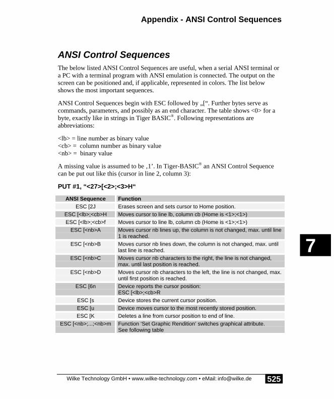
Appendix - ANSI Control Sequences
Wilke Technology GmbH • www.wilke-technology.com • eMail: [email protected]
7
525
ANSI Control SequencesThe below listed ANSI Control Sequences are useful, when a serial ANSI terminal ora PC with a terminal program with ANSI emulation is connected. The output on thescreen can be positioned and, if applicable, represented in colors. The list belowshows the most important sequences.
ANSI Control Sequences begin with ESC followed by „[“. Further bytes serve ascommands, parameters, and possibly as an end character. The table shows <0> for abyte, exactly like in strings in Tiger BASIC®. Following representations areabbreviations:
<lb> = line number as binary value<cb> = column number as binary value<nb> = binary value
A missing value is assumed to be ‚1’. In Tiger-BASIC® an ANSI Control Sequencecan be put out like this (cursor in line 2, column 3):
PUT #1, “<27>[<2>;<3>H“
ANSI Sequence FunctionESC [2J Erases screen and sets cursor to Home position.
ESC [<lb>;<cb>H Moves cursor to line lb, column cb (Home is <1>;<1>)ESC [<lb>;<cb>f Moves cursor to line lb, column cb (Home is <1>;<1>)
ESC [<nb>A Moves cursor nb lines up, the column is not changed, max. until line1 is reached.
ESC [<nb>B Moves cursor nb lines down, the column is not changed, max. untillast line is reached.
ESC [<nb>C Moves cursor nb characters to the right, the line is not changed,max. until last position is reached.
ESC [<nb>D Moves cursor nb characters to the left, the line is not changed, max.until first position is reached.
ESC [6n Device reports the cursor position:ESC [<lb>;<cb>R
ESC [s Device stores the current cursor position.ESC [u Device moves cursor to the most recently stored position.ESC [K Deletes a line from cursor position to end of line.
ESC [<nb>;...;<nb>m Function ‘Set Graphic Rendition’ switches graphical attribute.See following table

Appendix - ANSI Control Sequences
Wilke Technology GmbH • www.wilke-technology.com • eMail: [email protected]
7
526
ESC-m-Parameter Function0 All attributes OFF1 Bold ON2 Weak ON3 Italic ON5 Blink ON6 Fast blink ON7 Inverse ON8 Hidden ON
30...47 Different fore- and background colours

Appendix - Windows 95/98/NT Shortcuts
Wilke Technology GmbH • www.wilke-technology.com • eMail: [email protected]
7
527
Windows 95/98/NT ShortcutsThe table shows the most important Windows 95/98/NT shortcuts.
Eingabe FunktionF1 HelpF10 Activate menu bar optionsSHIFT + F10 Open a shortcut menu for the selected item
CTRL + C CopyCRTL + X CutCTRL + V PasteCTRL + A Select allCTRL + S SaveCTRL + N Open new windowCTRL + Z UndoCTRL + ESC Open Start menuCTRL + F4 Close current MDI windowCTRL + TAB Next child window / property tabCTRL + SHIFT + TAB Previous child window / property tabCTRL + O OpenCTRL + P PrintCTRL + Pos1 Top of documentCTRL + Ende End of documentCTRL + ALT + DEL Opens Task Manager window

Appendix - Windows 95/98/NT Shortcuts
Wilke Technology GmbH • www.wilke-technology.com • eMail: [email protected]
7
528
Eingabe FunktionWIN Open Start menuWIN + R Run dialog boxWIN + M Minimize allWIN + SHIFT + M Undo minimize allWIN + F1 HelpWIN + E Windows ExplorerWIN + F Find files or foldersWIN + D Minimize all open windows and display the
desktopWIN + CTRL + F Find computerWIN + CTRL + TAB Move focus from Start, to the Quick Launch
toolbar, to the system trayWIN + TAB Cycle through taskbar buttonsWIN + BREAK System Properties dialog box
ALT + TAB Switch to next running programALT + SHIFT + TAB Switch to previous running programALT + F4 Quit program / Close current windowALT + F6 Switch between multiple windows in the same
programALT + SPACE Display the main window’s System menuALT + ESC Switches between Explorer and all other
applicationsALT + - Display the MDI child window’s System menu

Appendix - Short-Cuts Tiger-BASIC® Version 5
Wilke Technology GmbH • www.wilke-technology.com • eMail: [email protected]
7
529
Short-Cuts Tiger-BASIC® Version 5Eingabe Funktion
Arrow keys One column left or right
Arrow keys One line up or down
STRG-Arrowkeys
One word further or back
PgUp, PgDn One page up or down
STRG-Pos1 Start of text
STRG-End End of text
STRG-F7/F8 Jump to next/previous error
Scroll bars Fast up/down
Find function Jump to specific place in text
Strg-S Save file
Strg-Z Undo
Strg-X Cut
Strg-C Copy
Strg-V Paste
Strg-A Select all
Strg-F Find
Strg-R Replace
F3 Find next
Strg-G Jump to line
Strg-F9 Show messages
Strg-M Show Tiger status
ALT-F5 View Evaluate/Modify
Strg-F5 View Watches

Appendix - Short-Cuts Tiger-BASIC® Version 5
Wilke Technology GmbH • www.wilke-technology.com • eMail: [email protected]
7
530
Eingabe Funktion
Strg-W View Refresh Watches
Strg-N View Add to Watches
F4 Start-Compile
F5 Start-Run
Strg-L Start-download Program
Strg-D Start-delete Program
F6 Debug-trace into (in Task)
ALT-F6 Debug-trace into (several lines, in Task)
F7 Debug-step over (in Task)
ALT-F7 Debug-step over (several lines, in Task)
F8 Debug-trace into (everywhere)
ALT-F8 Debug-trace into (several lines, everywhere)
Strg-T Debug-Run up to Cursor
Strg-H Debug-Stop Program
Strg-E Debug-Reset Program
F2 Debug-toggle breakpoint
ALT-F2 Debug-specify breakpoint
Strg-K Debug-delete all breakpoints
Strg-B Debug-Edit protection on/off
Strg-F3 Options Communication
F1 Help

Appendix - Designation of resistors and capacitors
Wilke Technology GmbH • www.wilke-technology.com • eMail: [email protected]
7
531
Designation of resistors and capacitorsDesignation of resistors / capacitors with specification of temperature coefficient(DIN-41429 / DIN-IEC-62 / IEC 115-1-4.5)
Color codesColor Figure Multiplier Tolerance Temp. coeff.
black 0 100 - ± 250 * 10-6/K
brown 1 101 ±1% ± 100 * 10-6/K
red 2 102 ±2% ± 50 * 10-6/K
orange 3 103 - ± 15 * 10-6/K
yellow 4 104 - ± 25 * 10-6/K
green 5 105 ±0,5% ± 20* 10-6/K
blue 6 106 ±0,25% ± 10 * 10-6/K
purple 7 107 ±0,1% ± 5 * 10-6/K
grey 8 108 - ± 1 * 10-6/K
white 9 109 - -
silver - 10-2 ±10% -
gold - 10-1 ±5% -
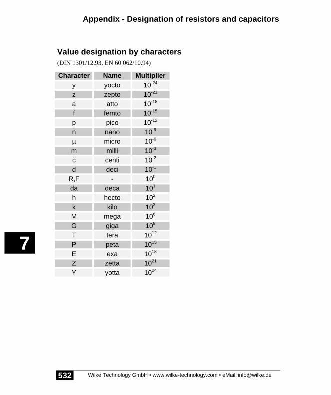
Appendix - Designation of resistors and capacitors
Wilke Technology GmbH • www.wilke-technology.com • eMail: [email protected]
7
532
Value designation by characters(DIN 1301/12.93, EN 60 062/10.94)
Character Name Multipliery yocto 10-24
z zepto 10-21
a atto 10-18
f femto 10-15
p pico 10-12
n nano 10-9
µ micro 10-6
m milli 10-3
c centi 10-2
d deci 10-1
R,F - 100
da deca 101
h hecto 102
k kilo 103
M mega 106
G giga 109
T tera 1012
P peta 1015
E exa 1018
Z zetta 1021
Y yotta 1024
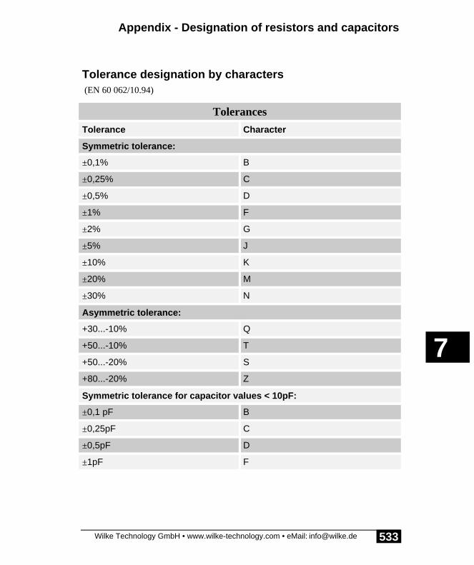
Appendix - Designation of resistors and capacitors
Wilke Technology GmbH • www.wilke-technology.com • eMail: [email protected]
7
533
Tolerance designation by characters (EN 60 062/10.94)
Tolerances
Tolerance Character
Symmetric tolerance:
±0,1% B
±0,25% C
±0,5% D
±1% F
±2% G
±5% J
±10% K
±20% M
±30% N
Asymmetric tolerance:
+30...-10% Q
+50...-10% T
+50...-20% S
+80...-20% Z
Symmetric tolerance for capacitor values < 10pF:
±0,1 pF B
±0,25pF C
±0,5pF D
±1pF F

Appendix - Designation of resistors and capacitors
Wilke Technology GmbH • www.wilke-technology.com • eMail: [email protected]
7
534
Position of color codes on resistors:
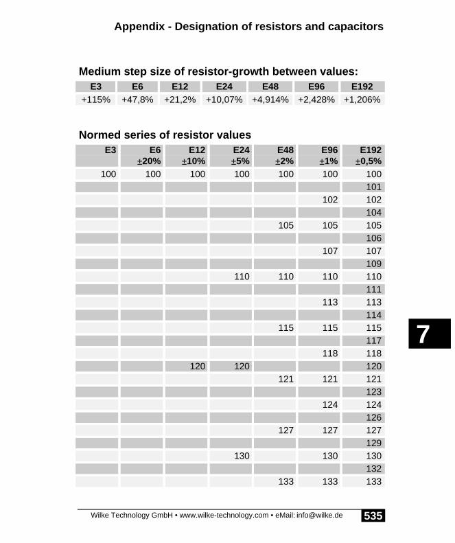
Appendix - Designation of resistors and capacitors
Wilke Technology GmbH • www.wilke-technology.com • eMail: [email protected]
7
535
Medium step size of resistor-growth between values:E3 E6 E12 E24 E48 E96 E192
+115% +47,8% +21,2% +10,07% +4,914% +2,428% +1,206%
Normed series of resistor valuesE3 E6
±20%E12
±10%E24±5%
E48±2%
E96±1%
E192±0,5%
100 100 100 100 100 100 100101
102 102104
105 105 105106
107 107109
110 110 110 110111
113 113114
115 115 115117
118 118120 120 120
121 121 121123
124 124126
127 127 127129
130 130 130132
133 133 133

Appendix - Designation of resistors and capacitors
Wilke Technology GmbH • www.wilke-technology.com • eMail: [email protected]
7
536
E3 E6±20%
E12±10%
E24±5%
E48±2%
E96±1%
E192±0,5%
135137 137
138140 140 140
142143 143
145147 147 147
149150 150 150 150 150
152154 154 154
156158 158
160 160162 162 162
164165 165
167169 169 169
172174 174
176178 178 178
180 180 180182 182
184187 187 187
189191 191
193196 196 196

Appendix - Designation of resistors and capacitors
Wilke Technology GmbH • www.wilke-technology.com • eMail: [email protected]
7
537
E3 E6±20%
E12±10%
E24±5%
E48±2%
E96±1%
E192±0,5%
198200 200 200
203205 205 205
208210 210
213215 215 215
218220 220 220 220 221 221
223226 226 226
229232 232
234237 237 237
240 240243 243
246249 249 249
252255 255
258261 261 261
264267 267
270 270 271274 274 274
277280 280
284287 287 287

Appendix - Designation of resistors and capacitors
Wilke Technology GmbH • www.wilke-technology.com • eMail: [email protected]
7
538
E3 E6±20%
E12±10%
E24±5%
E48±2%
E96±1%
E192±0,5%
291294 294
298300 301 301 301
305309 309
312316 316 316
320324 324
328330 330 330 332 332 332
336340 340
344348 348 348
352357 357
360 361365 365 365
370374 374
379383 383 383
388390 290 392 392
397402 402 402
407412 412
417422 422 422

Appendix - Designation of resistors and capacitors
Wilke Technology GmbH • www.wilke-technology.com • eMail: [email protected]
7
539
E3 E6±20%
E12±10%
E24±5%
E48±2%
E96±1%
E192±0,5%
427430 432 432
437442 442 442
448453 453
459464 464 464
470 470 470 470 470475 475
481487 487 487
493499 499
505510 511 511 511
517523 523
530536 536 536
542549 549
556560 560 562 562 562
569576 576
583590 590 590
597604 604
612620 619 619 619

Appendix - Designation of resistors and capacitors
Wilke Technology GmbH • www.wilke-technology.com • eMail: [email protected]
7
540
E3 E6±20%
E12±10%
E24±5%
E48±2%
E96±1%
E192±0,5%
626634 634
642649 649 649
657665 665
673680 680 680 681 681 681
690698 698
706715 715 715
723732 732
741750 750 750 750
759768 768
777787 787 787
796806 806
816820 820 825 825 825
835845 845
856866 866 866
876887 887
898910 909 909 909
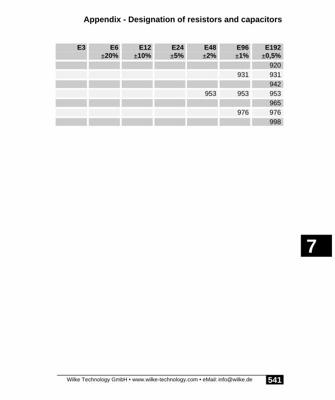
Appendix - Designation of resistors and capacitors
Wilke Technology GmbH • www.wilke-technology.com • eMail: [email protected]
7
541
E3 E6±20%
E12±10%
E24±5%
E48±2%
E96±1%
E192±0,5%
920931 931
942953 953 953
965976 976
998

Appendix - Designation of resistors and capacitors
Wilke Technology GmbH • www.wilke-technology.com • eMail: [email protected]
7
542
Empty Page

Appendix - BASIC-Tiger® module A – Pin description
Wilke Technology GmbH • www.wilke-technology.com • eMail: [email protected]
7
543
BASIC-Tiger® module A – Pin descriptionOverview of I/O pin-usage of the most important device drivers. Several functions arefixed to the appropriate pin (PWM, PLSO1, PLSIN1), others are only standardassignment, but can be redirected to other pins (LCD, Strobe, Busy):
Function Pin desc. Pin no. Pin no Pin desc. Function
res. 1 46 VCC
D0 L60 2 45 Batt.
D1 L61 3 44 AGND
D2 L62 4 43 Vref
D3 L63 5 42 An3
D4 L64 6 41 An2
D5 L65 7 40 An1
D6 L66 8 39 An0
D7 L67 9 38 Alarm
Busy L70 10 37 L41/PC
Strobe L71 11 36 L40
PWM0 L72 12 35 L42 Beep
PWM1 L73 13 34 L37 LCD1-RS
LCD-WR L80 14 33 L36 LCD1-E
LCD-RD L81 15 32 L35 INE
LCD-CE L82 16 31 L34 Dclk
LCD-CD L83 17 30 L33 Aclk
PLSIN1 L84 18 29 L95 RTS
L85 19 28 L94 Rx1
PLSO1 L86 20 27 L93 Tx1
L87 21 26 L92 CT0
Reset-in 22 25 L91 Rx0
GND 23 24 L90 Tx0

Appendix - BASIC-Tiger® module A – Pin description
Wilke Technology GmbH • www.wilke-technology.com • eMail: [email protected]
7
544
Empty Page

Appendix - BASIC-Tiger® module A – Pin description
Wilke Technology GmbH • www.wilke-technology.com • eMail: [email protected]
7
545
Blank table BASIC-Tiger®-Module A as copy pattern. Project:
Function Pindesc.
Pinno
Pinno
Pindesc.
Function
res. 1 46 VCC
L60 2 45 Batt.
L61 3 44 AGND
L62 4 43 Vref
L63 5 42 An3
L64 6 41 An2
L65 7 40 An1
L66 8 39 An0
L67 9 38 Alarm
L70 10 37 L41/PC
L71 11 36 L40
L72 12 35 L42
L73 13 34 L37
L80 14 33 L36
L81 15 32 L35
L82 16 31 L34
L83 17 30 L33
L84 18 29 L95
L85 19 28 L94
L86 20 27 L93
L87 21 26 L92
Reset-in 22 25 L91
GND 23 24 L90

Appendix - BASIC-Tiger® module A – Pin description
Wilke Technology GmbH • www.wilke-technology.com • eMail: [email protected]
7
546
Empty Page

Appendix - TINY-Tiger® – Pin description
Wilke Technology GmbH • www.wilke-technology.com • eMail: [email protected]
7
547
TINY-Tiger® – Pin descriptionOverview of I/O pin-usage of the most important device drivers. Several functions arefixed to the appropriate pin (PWM, PLSO1, PLSIN1), others are only standardassignment, but can be redirected to other pins (LCD, Strobe, Busy):
Function Pin desc. Pin no Pin no Pin desc. Function
D0 L60 1 44 VCC
D1 L61 2 43 Batt.
D2 L62 3 42 Vref
D3 L63 4 41 AGND
D4 L64 5 40 An3
D5 L65 6 39 An2
D6 L66 7 38 An1
D7 L67 8 37 An0
Busy L70 9 36 L41/PC
Strobe L71 10 35 res.
PWM0 L72 11 34 Alarm
PWM1 L73 12 33 L37 LCD1-RS
LCD-WR L80 13 32 L36 LCD1-E
LCD-RD L81 14 31 L35 INE
LCD-CE L82 15 30 L34 Dclk
LCD-CD L83 16 29 L33 Aclk
PLSIN1 L84 17 28 L95 RTS
L85 18 27 L94 Rx1
PLSO1 L86 19 26 L93 Tx1
L87 20 25 L92 CT0
Reset-in 21 24 L91 Rx0
GND 22 23 L90 Tx0

Appendix - TINY-Tiger® – Pin description
Wilke Technology GmbH • www.wilke-technology.com • eMail: [email protected]
7
548
Empty Page
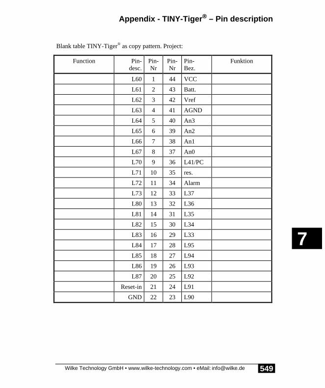
Appendix - TINY-Tiger® – Pin description
Wilke Technology GmbH • www.wilke-technology.com • eMail: [email protected]
7
549
Blank table TINY-Tiger® as copy pattern. Project:
Function Pin-desc.
Pin-Nr
Pin-Nr
Pin-Bez.
Funktion
L60 1 44 VCC
L61 2 43 Batt.
L62 3 42 Vref
L63 4 41 AGND
L64 5 40 An3
L65 6 39 An2
L66 7 38 An1
L67 8 37 An0
L70 9 36 L41/PC
L71 10 35 res.
L72 11 34 Alarm
L73 12 33 L37
L80 13 32 L36
L81 14 31 L35
L82 15 30 L34
L83 16 29 L33
L84 17 28 L95
L85 18 27 L94
L86 19 26 L93
L87 20 25 L92
Reset-in 21 24 L91
GND 22 23 L90

Appendix - TINY-Tiger® – Pin description
Wilke Technology GmbH • www.wilke-technology.com • eMail: [email protected]
7
550
Empty Page

Appendix - TINY-Tiger® Modul E – Pin description
Wilke Technology GmbH • www.wilke-technology.com • eMail: [email protected]
7
551
TINY-Tiger® Modul E – Pin descriptionOverview of I/O pin-usage of the most important device drivers. Several functions arefixed to the appropriate pin (PWM, PLSO1, PLSIN1), others are only standardassignment, but can be redirected to other pins (LCD, Strobe, Busy):
Function Pindesc.
Pinno
Pinno
Pindesc.
Function
D0 L60 1 28 VCC
D1 L61 2 27 L37 LCD1-RS
D2 L62 3 26 L36/An3 LCD1-E
D3 L63 4 25 L35/An2 INE
D4 L64 5 24 L34/An1 Dclk
D5 L65 6 23 L33/An0 Aclk
D6 L66 7 22 L41/PC
D7 L67 8 21 L85
LCD-WR L80 9 20 Reset-in
LCD-RD L81 10 19 L94 Rx1
LCD-CE L82 11 18 L93 Tx1
LCD-CD L83 12 17 L92/L86 CT0/PLSO1
PLSIN1 L84 13 16 L91/L87 Rx0
GND 14 15 L90 Tx0

Appendix - TINY-Tiger® Modul E – Pin description
Wilke Technology GmbH • www.wilke-technology.com • eMail: [email protected]
7
552
Empty Page

Appendix - TINY-Tiger® Modul E – Pin description
Wilke Technology GmbH • www.wilke-technology.com • eMail: [email protected]
7
553
Blank table TINY-Tiger® Module E as copy pattern. Project:
Function Pindesc.
Pinno
Pinno
Pindesc.
Function
L60 1 28 VCC
L61 2 27 L37
L62 3 26 L36/An3
L63 4 25 L35/An2
L64 5 24 L34/An1
L65 6 23 L33/An0
L66 7 22 L41/PC
L67 8 21 L85
L80 9 20 Reset-in
L81 10 19 L94
L82 11 18 L93
L83 12 17 L92/L86
L84 13 16 L91/L87
GND 14 15 L90

Appendix - TINY-Tiger® Modul E – Pin description
Wilke Technology GmbH • www.wilke-technology.com • eMail: [email protected]
7
554
Empty Page

Appendix - BASIC-Tiger® CAN module – Pin description
Wilke Technology GmbH • www.wilke-technology.com • eMail: [email protected]
7
555
BASIC-Tiger® CAN module – Pin descriptionOverview of I/O pin-usage of the most important device drivers. Several functions arefixed to the appropriate pin (PWM, PLSO1, PLSIN1), others are only standardassignment, but can be redirected to other pins (LCD, Strobe, Busy). The B-Row isnot listed, as most pins are unused and the used pins don’t allow variable functions:
Function Pin desc. Pin no Pin-no Pin desc. Function
res. 1 46 VCC
D0 L60 2 45 Batt.
D1 L61 3 44 AGND
D2 L62 4 43 Vref
D3 L63 5 42 An3
D4 L64 6 41 An2
D5 L65 7 40 An1
D6 L66 8 39 An0
D7 L67 9 38 Alarm
Busy L70 10 37 L41/PC
Strobe L71 11 36 L40
PWM0 L72 12 35 L42 Beep
PWM1 L73 13 34 L37 LCD1-RS
LCD-WR L80 14 33 L36 LCD1-E
LCD-RD L81 15 32 L35 INE
LCD-CE L82 16 31 L34 Dclk
LCD-CD L83 17 30 L33 Aclk
PLSIN1 L84 18 29 L95 RTS
L85 19 28 L94 Rx1
PLSO1 L86 20 27 L93 Tx1
21 26 L92 CT0
Reset-in 22 25 L91 Rx0
GND 23 24 L90 Tx0

Appendix - BASIC-Tiger® CAN module – Pin description
Wilke Technology GmbH • www.wilke-technology.com • eMail: [email protected]
7
556
Empty Page

Appendix - BASIC-Tiger® CAN module – Pin description
Wilke Technology GmbH • www.wilke-technology.com • eMail: [email protected]
7
557
Blank table BASIC-Tiger® CAN module as copy pattern.The B-Row is not listed, as most pins are unused and the used pins don’t allowvariable functions. Project:
Function Pindesc.
Pinno
Pinno
Pindesc.
Function
res. 1 46 VCC
L60 2 45 Batt.
L61 3 44 AGND
L62 4 43 Vref
L63 5 42 An3
L64 6 41 An2
L65 7 40 An1
L66 8 39 An0
L67 9 38 Alarm
L70 10 37 L41/PC
L71 11 36 L40
L72 12 35 L42
L73 13 34 L37
L80 14 33 L36
L81 15 32 L35
L82 16 31 L34
L83 17 30 L33
L84 18 29 L95
L85 19 28 L94
L86 20 27 L93
21 26 L92
Reset-in 22 25 L91
GND 23 24 L90

Appendix - BASIC-Tiger® CAN module – Pin description
Wilke Technology GmbH • www.wilke-technology.com • eMail: [email protected]
7
558