BASIC TECHNICAL INFORMATION MAST CLIMBING WORK PLATFORMS ... · PDF filebasic technical...
15
BASIC TECHNICAL INFORMATION MAST CLIMBING WORK PLATFORMS PM 200/210 MODELS B.F.T. SCAFFOLDING LTD (MAST CLIMBING DIVISION) MIDWAY DEPOT, STANBRIDGE ROAD, LEIGHTON BUZZARD BEDFORDSHIRE, LU7 9HR TEL: - 01525 853575 FAX: - 01525 374658 IPAF REG.MEMBER NO. 791 C.I.T.B. REGISTERED NO. 2311804 www.bftscaffolding.com [email protected]
Transcript of BASIC TECHNICAL INFORMATION MAST CLIMBING WORK PLATFORMS ... · PDF filebasic technical...
BASIC TECHNICAL INFORMATION
MAST CLIMBING WORK PLATFORMS
PM 200/210 MODELS
B.F.T. SCAFFOLDING LTD (MAST CLIMBING DIVISION)
MIDWAY DEPOT, STANBRIDGE ROAD, LEIGHTON BUZZARD
BEDFORDSHIRE, LU7 9HR
TEL: - 01525 853575 FAX: - 01525 374658
IPAF REG.MEMBER NO. 791
C.I.T.B. REGISTERED NO. 2311804
www.bftscaffolding.com

Midway Depot, Stanbridge Road, Leighton Buzzard, Beds, LU7 9HR
Tel: - (01525) 853575 – Fax: - (01525) 374658
E-mail: - [email protected]
Web: - www.bftscaffolding.com
IPAF Reg Member No. 791
C.I.T.B. REG NO. 2311804
B.F.T. MAST CLIMBING DIVISION
B.F.T. SCAFFOLDING LTD (MAST CLIMBING DIVISION)
MAST CLIMBING WORK PLATFORMS PM 200/210
MAST CLIMBING WORK PLATFORMS PM 200/210
TECHNICAL AND STRUCTURAL FEATURES
SINGL E MAST DOUBLE MAST TRIPLE MAST
Max Height: 130 M 130 M 130 M
Total Platform Length: 2.20 M – 10.0 M 10.0 M – 30.5 M 30. 5M – 40.0M
Max Platform Width 1.1 M – 2.4 M 1.1 M – 2.4 M 1.1 M – 2.4 M
Anchor Distance: Every 6 meters Every 6 meters Every 6 meters
Travel Speed: 7 meters /min 7 meters /min 7 meters /min
Lifting Capacity: Access Platform 1,600 kg 3,700 kg TBC
Platform Voltage: 3 Phase -380 v 3 Phase -380 v 3 Phase -380v
Power Source: Mains Generator Mains Generator Mains Generator
DOUBLE MAST climbing work platforms can be separated and used
individually as two SINGLE MAST platforms. Their traction units are
similar, and a separate electrical cabinet is supplied for each unit. In bi-mast models, the cabinets are linked with control possible from either
cabinet. We have also developed a system that allows the installation of
TRIPLE MAST platforms up to a maximum horizontal length of 40 m.
PLATFORM MODULES
Length 0.6 m & 1.5 m Width 0.9 m (PM 200) 1.1 m (PM 210)
The non-slip metallic grid floor makes cleaning and water removal easy, so improving safety conditions at work.
The PLATFORM MODULES are coupled together using 3 keyed bolts. They incorporate 1.1 m high balustrades.

Midway Depot, Stanbridge Road, Leighton Buzzard, Beds, LU7 9HR
Tel: - (01525) 853575 – Fax: - (01525) 374658
E-mail: - [email protected]
Web: - www.bftscaffolding.com
IPAF Reg Member No. 791
C.I.T.B. REG NO. 2311804
B.F.T. MAST CLIMBING DIVISION
B.F.T. SCAFFOLDING LTD (MAST CLIMBING DIVISION)
MAST CLIMBING WORK PLATFORMS PM 200/210
FAÇADE EXTENSIONS
Length 0.7m 1.3m 1.5m
Width 0.5m
FAÇADE EXTENSIONS are used to cover any spaces
between the platform and the façade. Thanks to
their modular system, ALHER MCWP can be adapted
for a perfect fit to the shape of any façade, by adjusting their working surface to the individual
profile of each site.
As well as extending the working surface area, this
reduces the risk of falls. Like the platform modules, the extensions have a
non-slip metallic grid floor.
The extensions are coupled to the platform modules using purpose-built
rails. Their two set screws are tightened until the desired distance is
achieved.
The space between every three façade extensions is covered by intermodule extensions.
The extension kit in front of the power unit is used to cover the space between the mast and the façade. Its hinged mechanism means it can be
positioned horizontally for working, then replaced in a vertical position when the machine is ascending and descending. An additional safety
system incorporated is an end of stroke device that blocks any movement
of the platform when the extension kit is in horizontal position.
The façade extensions include posts for balustrades that allow guards to be erected round the entire platform perimeter.
Midway Depot, Stanbridge Road, Leighton Buzzard, Beds, LU7 9HR
Tel: - (01525) 853575 – Fax: - (01525) 374658
E-mail: - [email protected]
Web: - www.bftscaffolding.com
IPAF Reg Member No. 791
C.I.T.B. REG NO. 2311804
B.F.T. MAST CLIMBING DIVISION
B.F.T. SCAFFOLDING LTD (MAST CLIMBING DIVISION)
MAST CLIMBING WORK PLATFORMS PM 200/210
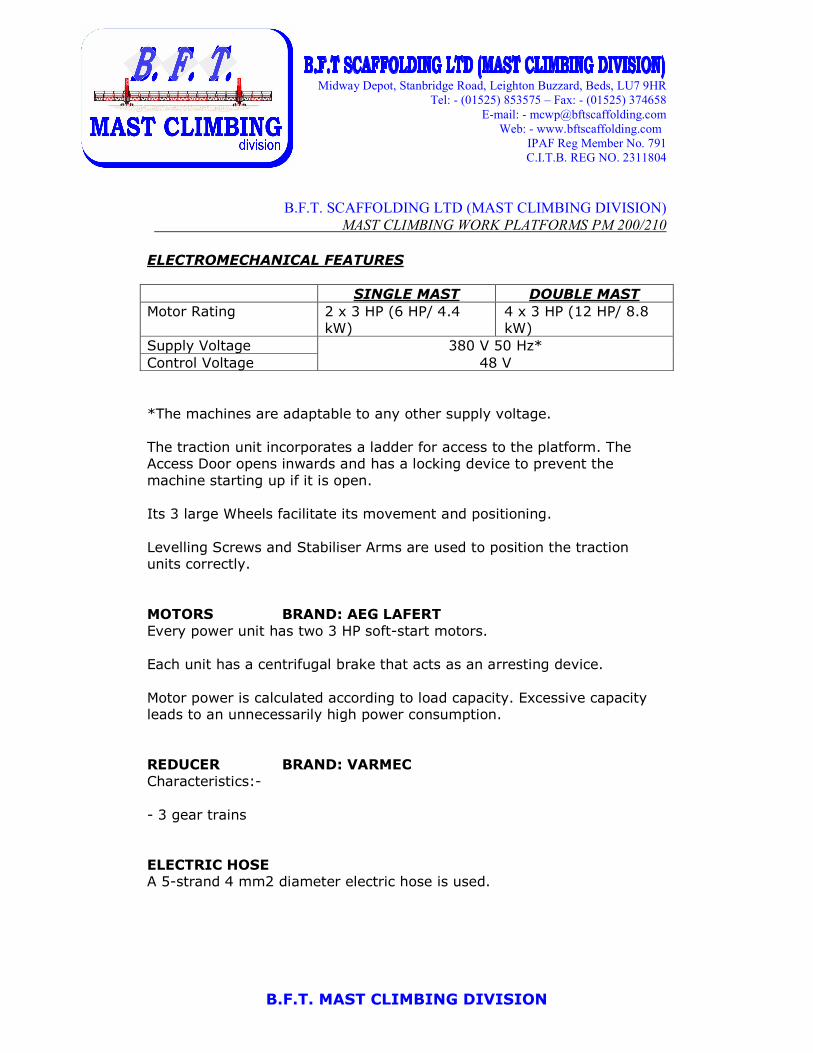
ELECTROMECHANICAL FEATURES
SINGLE MAST DOUBLE MAST
Motor Rating 2 x 3 HP (6 HP/ 4.4
kW)
4 x 3 HP (12 HP/ 8.8
kW)
Supply Voltage 380 V 50 Hz*
Control Voltage 48 V
*The machines are adaptable to any other supply voltage.
The traction unit incorporates a ladder for access to the platform. The Access Door opens inwards and has a locking device to prevent the
machine starting up if it is open.
Its 3 large Wheels facilitate its movement and positioning.
Levelling Screws and Stabiliser Arms are used to position the traction units correctly.
MOTORS BRAND: AEG LAFERT
Every power unit has two 3 HP soft-start motors.
Each unit has a centrifugal brake that acts as an arresting device.
Motor power is calculated according to load capacity. Excessive capacity leads to an unnecessarily high power consumption.
REDUCER BRAND: VARMEC
Characteristics:-
- 3 gear trains
ELECTRIC HOSE A 5-strand 4 mm2 diameter electric hose is used.

Midway Depot, Stanbridge Road, Leighton Buzzard, Beds, LU7 9HR
Tel: - (01525) 853575 – Fax: - (01525) 374658
E-mail: - [email protected]
Web: - www.bftscaffolding.com
IPAF Reg Member No. 791
C.I.T.B. REG NO. 2311804
B.F.T. MAST CLIMBING DIVISION
B.F.T. SCAFFOLDING LTD (MAST CLIMBING DIVISION)
MAST CLIMBING WORK PLATFORMS PM 200/210
SAFETY ELEMENTS
• Speed limiter / Centrifugal brake
System for preventing falls from the platform due to overspeed by the use of a speed limiter-arresting device on each mast, which can stop and support the platform in working conditions.
• Controlled manual lowering system
In the event of an interruption of the power supply.
• Automatic levelling device
End of stroke devices that stop the platform when it departs from the
horizontal position, both during normal movement and for the
conditions of use envisaged by the manufacturer. • Final section of mast with half-rack (painted red)
This prevents the platform running off the top of the mast.
• Rack proximity sensor
Located behind the rack. When the device cannot detect the rack, it detains the platform.
• Protected mains switch
Located in the control box that cuts the platform power supply. Is protected by a padlock that prevents unauthorised use when the
machine is not in service.
• Platform access doors
Open inwards. Locked by an electrically-operated locking bolt to prevent the platform from working if the door is open.
• Platform floor of non-slip metallic grid Permits removal of water and easy cleaning.
• Protective balustrades around the platform
The platforms have 1.10 m-high balustrades on the side opposite the façade and on both laterals. They consist of a 20 cm-high baseboard and two rails, one at half-height and the other on top.
If façade extension units are installed, balustrades can also be fitted on the façade side, thus protecting the entire platform perimeter.
• Mast protector 2 m-high metallic wire netting prevents any risk of trapping and/or
shearing in the area around the mast.
Midway Depot, Stanbridge Road, Leighton Buzzard, Beds, LU7 9HR
Tel: - (01525) 853575 – Fax: - (01525) 374658
E-mail: - [email protected]
Web: - www.bftscaffolding.com
IPAF Reg Member No. 791
C.I.T.B. REG NO. 2311804
B.F.T. MAST CLIMBING DIVISION
B.F.T. SCAFFOLDING LTD (MAST CLIMBING DIVISION)
MAST CLIMBING WORK PLATFORMS PM 200/210
• End of stroke microswitches
Fitted at both ground and upper level stops. There is also a third
safety microswitch that will activate if any of the earlier devices fails
to function.
• Low voltage (48 V) working
• Phase detector and control
Sequence relay to monitor missing phase or phase imbalance and to
protect against phase inversion.
OPERATION
The control panel is located on the platform, allowing workers to control
the machine's movement from the platform itself.
The up / down controls require sustained pressure, and the machine stops
if this pressure is removed.
Also includes emergency stop button.
An acoustic signal warns that the machine is in motion.
The platforms have a controlled manual descent system, by which they
can be lowered in the event of a power cut or other emergency. Each elevation unit is fitted with 2 levers that allow the brakes to be freed from
the motors-reducers. This is activated smoothly and simultaneously brings the platform slowly down to base level.

Midway Depot, Stanbridge Road, Leighton Buzzard, Beds, LU7 9HR
Tel: - (01525) 853575 – Fax: - (01525) 374658
E-mail: - [email protected]
Web: - www.bftscaffolding.com
IPAF Reg Member No. 791
C.I.T.B. REG NO. 2311804
B.F.T. MAST CLIMBING DIVISION
B.F.T. SCAFFOLDING LTD (MAST CLIMBING DIVISION)
MAST CLIMBING WORK PLATFORMS PM 200/210
ELEVATION SYSTEM – MAST FEATURES
RACK & PINION ELEVATION SYSTEM. MODULE 8 RACK
The module 8 rack provides more effective transmission and greater resistance and safety of elevation.
Each section of the rack is individually screwed onto the
mast element. This means that either of the two elements can be replaced as required without having to
detach the other.
Each power unit has 16 rollers to spread the load
uniformly when climbing the mast.
The mast has a square section and its internal structure is reinforced.
Its dimensions (500 x 500 x 1,500 mm, weight 64 Kg) make it easy to handle during the assembly/ dismantling process.
The galvanised finish gives the steel greater resistance and prolongs its
life.
SWIVEL STUDS
Each mast section has 4 M-18 swivel studs. These can be turned and inserted
into the lugs of the element above. Washers are then fitted and the adjusting
nuts tightened with a 125 Nm coupling
torque.
As the studs are secured to the mast sections, there is no risk of loss
during assembly/ dismantling work.
STANDARD MAST
SECTION Square
GUIDE TUBE 60 x 3,5 mm
HEIGHT 1.500 mm
WEIGHT 64 Kg
PM 200/ 210
FINISH Hop dip galvanised
Midway Depot, Stanbridge Road, Leighton Buzzard, Beds, LU7 9HR
Tel: - (01525) 853575 – Fax: - (01525) 374658
E-mail: - [email protected]
Web: - www.bftscaffolding.com
IPAF Reg Member No. 791
C.I.T.B. REG NO. 2311804
B.F.T. MAST CLIMBING DIVISION
B.F.T. SCAFFOLDING LTD (MAST CLIMBING DIVISION)
MAST CLIMBING WORK PLATFORMS PM 200/210
STANDARDS
The mast Climbers we provide/use here at B.F.T., (ALHER PM 200/210
MODELS) have been designed, manufactured and tested by the manufacturer according to the following standards:
▪ Machinery Directive 98/37/EC
▪ EN 292/1. Safety of machinery. Basic concepts, general principles
for design. Part 1. Basic terminology, methodology.
▪ EN 292/2. Safety of machinery. Basic concepts, general principles
for design. Part 2. Technical principles and specifications.
▪ EN 294. Safety of machinery. Safety distances to prevent danger zones from being reached by the upper limbs.
▪ EN-349. Safety of machinery. Minimum gaps to avoid crushing of parts of the human body.
▪ EN- 418. Safety of machinery. Emergency stop equipment,
functional aspects. Principles for design.
▪ EN-614/1. Safety of machinery. Ergonomic design principles. Part 1.
Terminology and general principles. ▪ EN- 953. Safety of machinery Guards. General requirements for the
design and construction of fixed and movable guards.
▪ EN-954/1. Safety of machinery. Safety-related parts of control
systems. Part 1: General principles for design
▪ EN-1050. Safety of machinery. Principles for risk assessment.
▪ EN – 1495. Lifting platforms. Mast climbing work platforms.
▪ EN- 60.204/1.Safety of machinery. Electrical equipment of
machines. Part 1. General requirements.
▪ ISO 6336. Calculation of load capacity of spur and helical gears.
Midway Depot, Stanbridge Road, Leighton Buzzard, Beds, LU7 9HR
Tel: - (01525) 853575 – Fax: - (01525) 374658
E-mail: - [email protected]
Web: - www.bftscaffolding.com
IPAF Reg Member No. 791
C.I.T.B. REG NO. 2311804
B.F.T. MAST CLIMBING DIVISION
B.F.T. SCAFFOLDING LTD (MAST CLIMBING DIVISION)
MAST CLIMBING WORK PLATFORMS PM 200/210
ASSEMBLY
NOTE: Detailed instructions for assembly of the Mast Climbing Work
Platforms are given in the assembly, operating and maintenance manual that accompanies the machine. This dossier is only intended to cover a
few aspects of the assembly process in general.
1. Before starting the installation:
You must:
a. Obtain the relevant regulatory permits for installing the machine.
b. Check that there is a power supply, prepare the electrical connection.
c. Order any auxiliary equipment you may need for mounting the
platform in situ (mobile crane, tower crane, etc.)
2. Foundations
You must prepare adequate foundations for mounting the platform base, to ensure its stability. Concrete must be at least 150 mm thick, and its
dimensions will vary depending on whether the platform is single mast or double mast, and if stabiliser arms are to be attached.
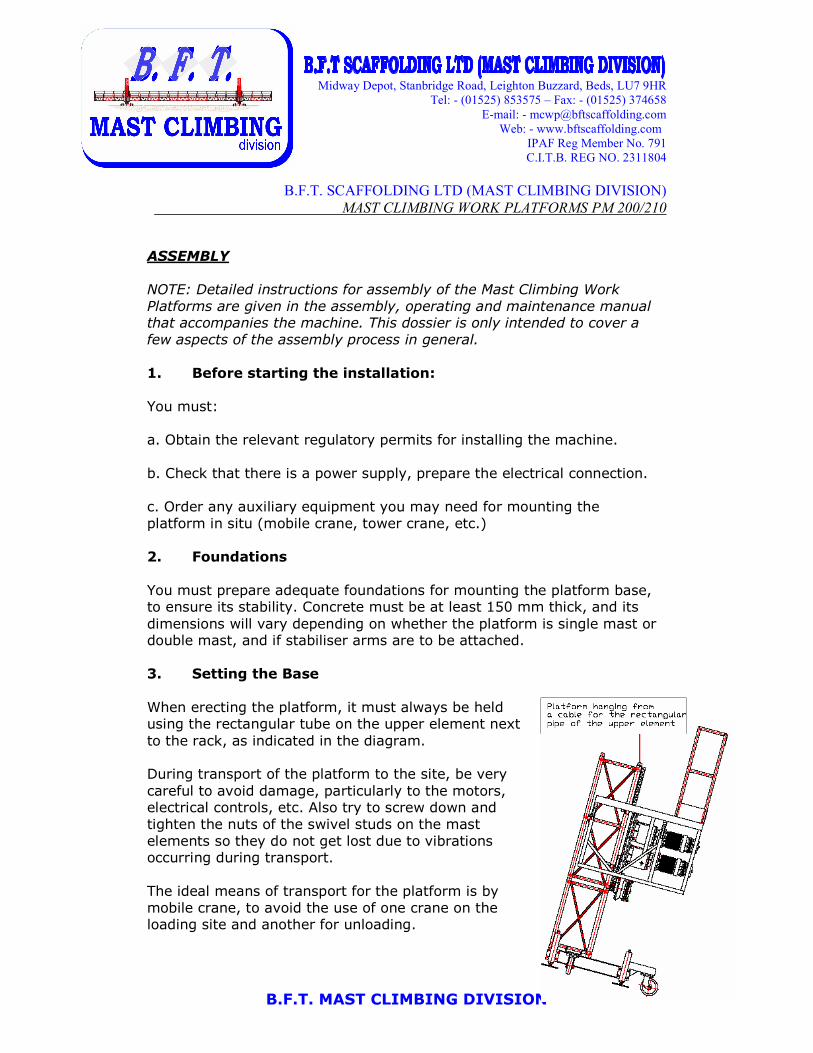
3. Setting the Base
When erecting the platform, it must always be held using the rectangular tube on the upper element next
to the rack, as indicated in the diagram. During transport of the platform to the site, be very
careful to avoid damage, particularly to the motors, electrical controls, etc. Also try to screw down and
tighten the nuts of the swivel studs on the mast
elements so they do not get lost due to vibrations occurring during transport.
The ideal means of transport for the platform is by
mobile crane, to avoid the use of one crane on the loading site and another for unloading.

Midway Depot, Stanbridge Road, Leighton Buzzard, Beds, LU7 9HR
Tel: - (01525) 853575 – Fax: - (01525) 374658
E-mail: - [email protected]
Web: - www.bftscaffolding.com
IPAF Reg Member No. 791
C.I.T.B. REG NO. 2311804
B.F.T. MAST CLIMBING DIVISION
B.F.T. SCAFFOLDING LTD (MAST CLIMBING DIVISION)
MAST CLIMBING WORK PLATFORMS PM 200/210
BASE SUPPORT
SINGLE MAST PLATFORM
The base of single mast platforms must always be assembled using four
stabiliser arms, as indicated in the diagram. If lack of space prevents this, and for platforms of 10 m long or less, the base can be installed using only two stabiliser arms (always with one at each side).
DOUBLE MAST PLATFORM
Double mast platforms do not require the stabiliser arms to be secured to
the base. The fifth levelling screw is not required either; the four end
screws are sufficient.

Midway Depot, Stanbridge Road, Leighton Buzzard, Beds, LU7 9HR
Tel: - (01525) 853575 – Fax: - (01525) 374658
E-mail: - [email protected]
Web: - www.bftscaffolding.com
IPAF Reg Member No. 791
C.I.T.B. REG NO. 2311804
B.F.T. MAST CLIMBING DIVISION
B.F.T. SCAFFOLDING LTD (MAST CLIMBING DIVISION)
MAST CLIMBING WORK PLATFORMS PM 200/210
4. Assembly of the Platform modules Single Mast Platform
No platform assembly operation must be carried out with the platform
level more than 2 metres above the ground.
1.- Installing the elevation unit (attaching the stabilisers in the position
described above).
2.- Earthing of the electrical connection. 3.- Levelling of the elevation unit using its levelling screws.
4.- When coupling platform modules, alternate the side from which you
assemble the elevation unit to ensure it remains as stable as possible at
all times. First couple the module using bolts and secure it with locking pins to one side of the elevation unit, then go on to attach another
module, this time to the other side of the unit.
Initially,
only attach 2
platform modules to each side of the elevation unit
(7m length), adding their respective balustrades. If 3 platform modules
areto be attached to each side of the unit, to reach the maximum length of 10m, the last 2 modules must only be added after the first stay or
bracing has been assembled on the structure.
There should be the same number of platforms on each side, or failing that, the difference should be only 0.6 metres (a small platform module).

Midway Depot, Stanbridge Road, Leighton Buzzard, Beds, LU7 9HR
Tel: - (01525) 853575 – Fax: - (01525) 374658
E-mail: - [email protected]
Web: - www.bftscaffolding.com
IPAF Reg Member No. 791
C.I.T.B. REG NO. 2311804
B.F.T. MAST CLIMBING DIVISION
B.F.T. SCAFFOLDING LTD (MAST CLIMBING DIVISION)
MAST CLIMBING WORK PLATFORMS PM 200/210
All front balustrades must be positioned securely by tightening their screws. The balustrades must always be fitted, except as required when
loading and unloading operations at ground level.
WARNING: Assembly or dismantling of the single mast platform must always be carried out with
stabiliser arms attached.
Double Mast Platform
The safety measures to be taken for this platform are the same as those
already discussed for Single mast platforms.
First, position the elevation units. The two units are identical, so it does
not matter whether they are installed on the left or the right. In double
mast platforms, you do not need to fit either the stabiliser arms or the fifth levelling screw.
To assemble the elevation unit bridge, position the modules one after the other. If there is a gradient, start assembly with the elevation unit on the
lower part of the gradient. Join and secure each module until you reach the other elevation unit. Units must be levelled and bolts and balustrades
positioned as described for Single mast platforms.
When joining the last module of the platform’s central bridge to the
second elevation unit, you may wish to connect the electrical controls to the elevation units and the power supply to raise or lower the unit,
making it easier to position the bolts.
WARNING: The lowest bolt of the first and last platform module in the central part must not be
attached either for assembly nor in normal
operation.

Midway Depot, Stanbridge Road, Leighton Buzzard, Beds, LU7 9HR
Tel: - (01525) 853575 – Fax: - (01525) 374658
E-mail: - [email protected]
Web: - www.bftscaffolding.com
IPAF Reg Member No. 791
C.I.T.B. REG NO. 2311804
B.F.T. MAST CLIMBING DIVISION
B.F.T. SCAFFOLDING LTD (MAST CLIMBING DIVISION)
MAST CLIMBING WORK PLATFORMS PM 200/210
5. Assembly of Mast
a. Positioning of the Mast Elements
All masts can be assembled by two people. The process described must
be duplicated if a bimast platform is being assembled.
First, load the mast elements (3) and the bracing tubes required for the first bracing to the platform. Use two people to place the next
element over the element below, securing it with 4 swivel studs. To
raise the element more easily, you may also use a pole and winch.
NOTE: You may also use a crane, provided that you ensure appropriate
safety measures are taken. If you do so, do not unite more than 4
mast elements at a time.
The platform must be raised until the rack detector is roughly 20 cm
away from the end of the platform (if raised too far, the detector will stop its ascent).
Install all the mast elements required to reach the height where the first bracing is to be attached. As a rule, 2 elements should be attached
first, then the third element braced. The platform must not move over this element until it is anchored in place.
Next proceed with the bracing as described below.
After completing the bracing, go down again to load up the mast elements and bracing tubes required for the next bracing to the
building. Repeat this process until the entire run of the platform is completed.
The final mast element is always the one with only a half rack (painted red) which acts as a safety device.
Note: You must check that the swivel studs, the lug welds and all components involved in coupling the mast elements are in good
condition.
Midway Depot, Stanbridge Road, Leighton Buzzard, Beds, LU7 9HR
Tel: - (01525) 853575 – Fax: - (01525) 374658
E-mail: - [email protected]
Web: - www.bftscaffolding.com
IPAF Reg Member No. 791
C.I.T.B. REG NO. 2311804
B.F.T. MAST CLIMBING DIVISION
B.F.T. SCAFFOLDING LTD (MAST CLIMBING DIVISION)
MAST CLIMBING WORK PLATFORMS PM 200/210
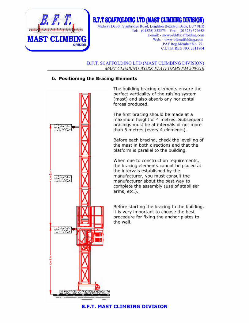
b. Positioning the Bracing Elements
The building bracing elements ensure the
perfect verticality of the raising system (mast) and also absorb any horizontal
forces produced.
The first bracing should be made at a maximum height of 4 metres. Subsequent
bracings must be at intervals of not more
than 6 metres (every 4 elements).
Before each bracing, check the levelling of
the mast in both directions and that the
platform is parallel to the building.
When due to construction requirements,
the bracing elements cannot be placed at the intervals established by the
manufacturer, you must consult the manufacturer about the best way to complete the assembly (use of stabiliser
arms, etc.).
Before starting the bracing to the building,
it is very important to choose the best
procedure for fixing the anchor plates to the wall.

Midway Depot, Stanbridge Road, Leighton Buzzard, Beds, LU7 9HR
Tel: - (01525) 853575 – Fax: - (01525) 374658
E-mail: - [email protected]
Web: - www.bftscaffolding.com
IPAF Reg Member No. 791
C.I.T.B. REG NO. 2311804
B.F.T. MAST CLIMBING DIVISION
B.F.T. SCAFFOLDING LTD (MAST CLIMBING DIVISION)
MAST CLIMBING WORK PLATFORMS PM 200/210
First secure the anchor plates to the wall (these can be anchored either to
the frontage or at each floor) as appropriate. With the mast levelled, position the two 48 support tubes so that each
forms a 30º angle with the perpendicular at the façade.
The joints must be made using flanges.
c. Installation of Other Elements
Assembly of the platform is completed by positioning the upper and lower
buffers, the self-levelling rods (for the Double mast platform), mast
protectors, etc…