Basic Series Vario Series -...
140
Analog Panel Meters Preference Program Basic Series Vario Series www www.klinkmann.com
Transcript of Basic Series Vario Series -...

Analog Panel MetersPreference ProgramBasic SeriesVario Series
wwwwww.klinkmann.com

Analog Panel Meters • Preference ProgramCertificates
DIN EN ISO 9001:2000 - Certificate
Germanischer Lloyd - Certificates
wwwwww.klinkmann.com
GMW · Kleinreuther Weg 88 · 90408 Nuremberg · Germany · Phone: +49 (0) 911 3502-0 · Fax: +49 (0) 911 3502-307 · E-Mail: [email protected] 3
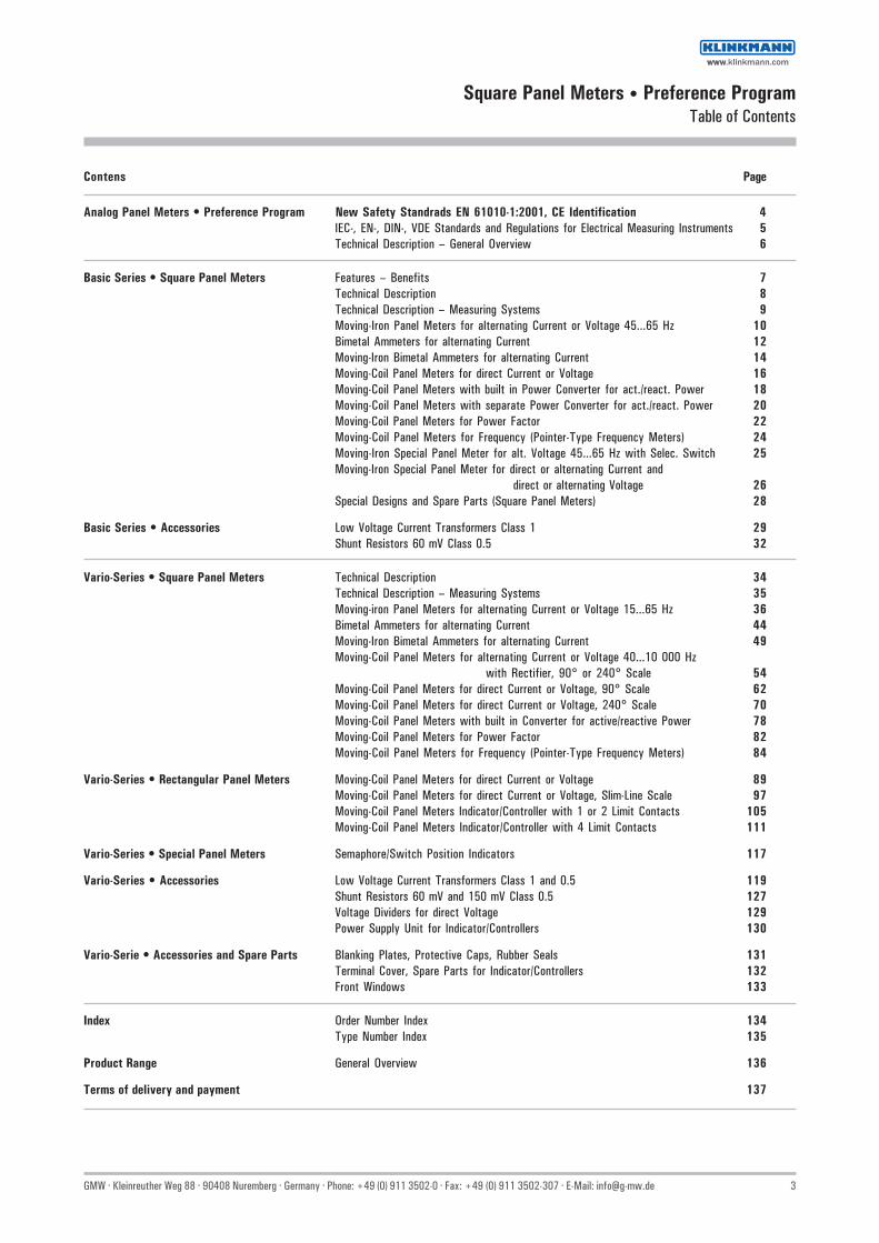
Square Panel Meters • Preference ProgramTable of Contents
Contens Page
Analog Panel Meters • Preference Program New Safety Standrads EN 61010-1:2001, CE Identification 4IEC-, EN-, DIN-, VDE Standards and Regulations for Electrical Measuring Instruments 5Technical Description – General Overview 6
Basic Series • Square Panel Meters Features – Benefits 7Technical Description 8Technical Description – Measuring Systems 9Moving-Iron Panel Meters for alternating Current or Voltage 45...65 Hz 10Bimetal Ammeters for alternating Current 12Moving-Iron Bimetal Ammeters for alternating Current 14Moving-Coil Panel Meters for direct Current or Voltage 16Moving-Coil Panel Meters with built in Power Converter for act./react. Power 18Moving-Coil Panel Meters with separate Power Converter for act./react. Power 20Moving-Coil Panel Meters for Power Factor 22Moving-Coil Panel Meters for Frequency (Pointer-Type Frequency Meters) 24Moving-Iron Special Panel Meter for alt. Voltage 45...65 Hz with Selec. Switch 25Moving-Iron Special Panel Meter for direct or alternating Current and
direct or alternating Voltage 26Special Designs and Spare Parts (Square Panel Meters) 28
Basic Series • Accessories Low Voltage Current Transformers Class 1 29Shunt Resistors 60 mV Class 0.5 32
Vario-Series • Square Panel Meters Technical Description 34Technical Description – Measuring Systems 35Moving-iron Panel Meters for alternating Current or Voltage 15...65 Hz 36Bimetal Ammeters for alternating Current 44Moving-Iron Bimetal Ammeters for alternating Current 49Moving-Coil Panel Meters for alternating Current or Voltage 40...10 000 Hz
with Rectifier, 90° or 240° Scale 54Moving-Coil Panel Meters for direct Current or Voltage, 90° Scale 62Moving-Coil Panel Meters for direct Current or Voltage, 240° Scale 70Moving-Coil Panel Meters with built in Converter for active/reactive Power 78Moving-Coil Panel Meters for Power Factor 82Moving-Coil Panel Meters for Frequency (Pointer-Type Frequency Meters) 84
Vario-Series • Rectangular Panel Meters Moving-Coil Panel Meters for direct Current or Voltage 89Moving-Coil Panel Meters for direct Current or Voltage, Slim-Line Scale 97Moving-Coil Panel Meters Indicator/Controller with 1 or 2 Limit Contacts 105Moving-Coil Panel Meters Indicator/Controller with 4 Limit Contacts 111
Vario-Series • Special Panel Meters Semaphore/Switch Position Indicators 117
Vario-Series • Accessories Low Voltage Current Transformers Class 1 and 0.5 119Shunt Resistors 60 mV and 150 mV Class 0.5 127Voltage Dividers for direct Voltage 129Power Supply Unit for Indicator/Controllers 130
Vario-Serie • Accessories and Spare Parts Blanking Plates, Protective Caps, Rubber Seals 131Terminal Cover, Spare Parts for Indicator/Controllers 132Front Windows 133
Index Order Number Index 134Type Number Index 135
Product Range General Overview 136
Terms of delivery and payment 137
wwwwww.klinkmann.com

4 GMW · Kleinreuther Weg 88 · 90408 Nuremberg · Germany · Phone: +49 (0) 911 3502-0 · Fax: +49 (0) 911 3502-307 · E-Mail: [email protected]
Analog Panel Meters • Preference ProgramNew Safety Standards EN 61010-1:2001, CE Identification
When selling a product within the European Union the CE Identification on the product, the packaging or the instruction manual is compulsory. The CE declaration of conformityconfirms compliance with European regulations (low voltage directive, EMC directive).
The CE Identification is not addressed to the consumer primarily; it is addressed to the controlling institution of the market. The requirements of the harmonisation directive arederived by the market controlling institution by using the CE identification.Standards, that are to be used compulsorily, are mentioned in the low voltage directive 73/23 EWG:
Norm DIN EN 60051Safety Norm EN 61010-1:2001 (VDE 0411-1:2002, IEC 61010-1:2002)
For protection against dangerous body currents, the clearance and creepage distances at the same operating voltages had to be increased in comparison to earlier standards. Thus thesafety of the user is further increased.
By introducing complex changes in the former design of panel meters, in particular of analog panel meters, GMW meets the demands of EN 61010-1:2001.This development is protected by the European Patent EP1 508 786 A2.
All offered analog panel meters comply with this standard.
Category of measurement and operating voltage
CAT I Measurements in circuits that are not connected directly to the mains supply(e.g. secondary site of over voltage-proof power supply units, batteries)
CAT II Measurements in circuits that are connected directly to a low voltage mains supply by plugs(e.g. household appliances, office machines)
CAT III Measurements on building installations
CAT IV Mesurement at power sources for low voltage
Panel meters are primarily used in building installation. Therefore they are to be labelled with CAT III and the allowable operating voltage, e.g. CAT III 600V.
The operating voltage between the earth and the terminal connections of the meter is measured. Example:A panel meter that is labelled with “CAT III 600V“ can be used to measure up to 1000 V in a 3-phase system.The maximal external conductor voltage against earth accounts for 600 V.
CAT I CAT II CAT III CAT IVElectronics 1-phase loads 3-phase on building 3-phase at electric
that are connected installations utilities overhead lineto a power socket
wwwwww.klinkmann.com

GMW · Kleinreuther Weg 88 · 90408 Nuremberg · Germany · Phone: +49 (0) 911 3502-0 · Fax: +49 (0) 911 3502-307 · E-Mail: [email protected] 5
Analog Panel Meters • Prefernce ProgramIEC-, EN-, DIN-, VDE-Standards and Regulations for Electrical Meters
Regulations and StandardsOur meters and indicator/controllers comply with the regulations of the EuropeanGuidelines 73/23/EWG and 89/336/EWG. This is confirmed by the compliance withthe following standards:IEC/EN 61010-1/A2. VDE 0411-1/A1(Safety Regulations)IEC 60 051/EN 60 051/DIN EN 60 051 (Meters with Scale Display)EN 50 081-2: 1993 EMC (Emitted Interference, Industries)EN 50 082-2: 1995 EMC (Interference Resistance, Industries)Given below are the most important regulations for the fabrication and the requiredproperties of electrical meters.
AccuracyThe accuracy of a meter or an accesory is given by the limits of basic errors andinfluence effects.An occuring error, when meter and/or accessories is/are operated under referenceconditions (Tab. I-1 DIN EN 60 051) is reffered to as intrinsic error in contrast to theinfluence error when the instrument is not operated under reference conditions, butwithin the limits of its nominal range of use (Tab. II-1 DIN EN 60 051).Our meters and indicator/controllers correspond to class 1.5 as long as no other class ismentioned for certain types. If possible our meters can be produced for a higher class ofaccuracy (class 1).The class is given on the scale, e.g.:1.5 class sign for error in indication, expressed in percent of reference value.The reference value corresponds to the upper measuring range value with the followingexceptions:
• the sum of electrical values, that correspond to both limits of the measuring range. This applies only when both the mechanical and the electrical zero point are located within the scale range
• 90 electrical degress for power factor meters
The reference value corresponds to:
• the sum of electrical values, that correspond to both limits of the measuring range, independent from the algebraic sign. This applies only when both the mechanical and the eletrical zero point are located within the scale range;
• a quadrant with phase meters;
• the difference of resistance values of both limits of the measuring range. This applies for resistance meters with linear scales;
• the scale-length with instruments (e.g. resistance meters) with non-linear scale, that have no separate linear scales;
• the nominal value for accessories.
Scale and Pointer TypesThe scales and pointers of our measuring instruments comply with DIN 43 802, part 2through 4.
Protection per DIN VDE 0470, Part 1 (EN 60 529)Our measuring instruments and limit transducers comply with the following protectionclass per DIN VDE 0470, part1 (EN 60529), if not stated different:IP 52 for front of housingIP 00 for clampsIP 10 for clamps with mounted terminal cover
Safety RegulationsOur measuring instruments comply with DIN EN 61 010-1 (IEC 1010-1) and aredesigned for:• Category of Over voltage III (CAT III / CAT II)• Pollution Degree 2• Operating Voltage = Maximum value of nominal voltage above earth (effective value of direct voltage or alternating voltage), see table below.
Type Nominal Voltage
3-Phase- 3-Phase- Outer to 4-Wire-System 3-Wire-System Neut. Cond.
EQB 72 EQB 96 600 / 1000 V 1000 V 600 V EQB 72/U6 EQB 96/U6 DQB 72 DQB 96 MQB 72 MQB 96 MEQB 72 MEQB 96 DQB 72 MV DLMQB 96 FQB 72 DQB 96 MV DLQB 72 FQB 96
DLQB 96
V-AQS 72 V-AQS 96 V-PQS 72 V-PQS 96 V-MQS 72 V-MQS 96 V-MAQS 72 V-MAQS 96 V-PQ 72-250 V-PQ 96-250 V-FZQS 72 V-FZQS 96
V-LM 96 AQS 144 V-LM 96-250 PQS 144 V-LF 96 MQS 144 AMQS 144 PQ 144-250
EQB 48 AQS 48 W 230 / 400 V 500 V 300 V DQB 48 PQS 48 W MQB 48 V-MQS 48 DQB 48 MV V-PQ 48-250 DLQB 48 FZQS 48 W FQB 48 FkN 2
PF 48x241) PFF 001) 150 V PFF 72x241) PFF 0 PF 72x362) PFFN 96x24 M2)
PFFN 96x242) PFN 96x482)
PFN 96x242) PFN 96x48 M2)
DPR 144 F PF 144x72 KODPR 144 F KODPR 144 SE
1) Operating Voltage 100 V2) Operating Voltage 600 V
Meters with dial illumination,with prot. cur. transformer reduced operating voltage!and for marine applications
wwwwww.klinkmann.com
6 GMW · Kleinreuther Weg 88 · 90408 Nuremberg · Germany · Phone: +49 (0) 911 3502-0 · Fax: +49 (0) 911 3502-307 · E-Mail: [email protected]
Analog Panel Meters • Preference ProgramTechnical Description - General Overview
Vibration and Mechanical Shock ResistanceInfluence factors for vibration and shock have been set forth in DIN EN 60 051. Ourmeasuring instruments comply with these requirements and are available as follows(see respective data sheet for individual availability):
Mechanical Shock Resistance Vibration Resistance Stress
Standard model 15 g 1.5 g11 ms 5 ... 55 Hz
Enhanced requirements. 30 g 2.5 g LN56 11 ms 5 ... 55 Hz Enhanced requirements. 50 g 5.0 g LN55 (Vario-Series only) 11 ms 5 ... 55 Hz
Effects of Vibration and ShockUnless otherwise specified. class 1 and higher measuring instruments and Accessoriesmust withstand the following shock and vibration test. to which they are subjectedduring the course of type testing:
Vibration TestVibration testing must be performed with the following specifications:– Sweep frequency range: 10 Hz – 55 Hz – 10 Hz– Wave amplitude: 0.15 mm (corresponds to 1.5 g at 50 Hz)– Number of sweep cycles: 5– Sweep velocity: 1 octave per minute
The vibration plane is vertical and the measuring instrument is mounted to the vibrationtable in its usual operating position.
Shock TestThe shock test must be performed with the following specifications:– Peak acceleration: a) 147 m/s2 (15 g) b) 490 m/s2 (50 g)– No further explanation is required for peak acceleration value a).The manufacturer must indicate a peak acceleration value of 490 m/s2 for value b).– Waveshape: semi-sinusoidal– Number of shocks: 3 shocks each in both directions for 3 mutually perpendicular axes (a total of 18 shocks)– Shock duration: 11 ms
The measuring instrument must be secured such that one of the three axes correspondsto the direction of motion of the rational axis of the measuring mechanism.After completion of this test, an additional measuring error of 100% of the error classrating may not be exceeded.
Scale and Pointer TypesScale and pointer types for quadrant and circular scales are defined in DIN 43 802,parts 2 through 4 (as of size 48 x 48 mm), as well as for horizontal and vertical scales(as of size 48 x 24 mm).Our square and rectangular panel meters with edgewise scale are in compliance withthese standards.
Climate-Proof Measuring InstrumentsIn their “ tropic resistant“ versions, our measuring instruments are specially well suitedfor:– Moisture endangered areas in the temperate zones– Indoor use in dry tropics– Indoor use in the wet tropics, during which condensation or seepage water, which may be caused by air-conditioning, must be avoided
Range of Application (Climatic Demands)
Climatic Demands standard tropic resistant
Operating Temperature –25°C ... +40°C –25°C ... +55°C
Relative Humidity: annual mean ≤65% (at 21°C) ≤75% (at 21°C)30 days per year ≤85% (at 25°C) ≤95% (at 25°C)remaining days ≤75% (at 23°C) ≤85% (at 23°C)
Condensation none none
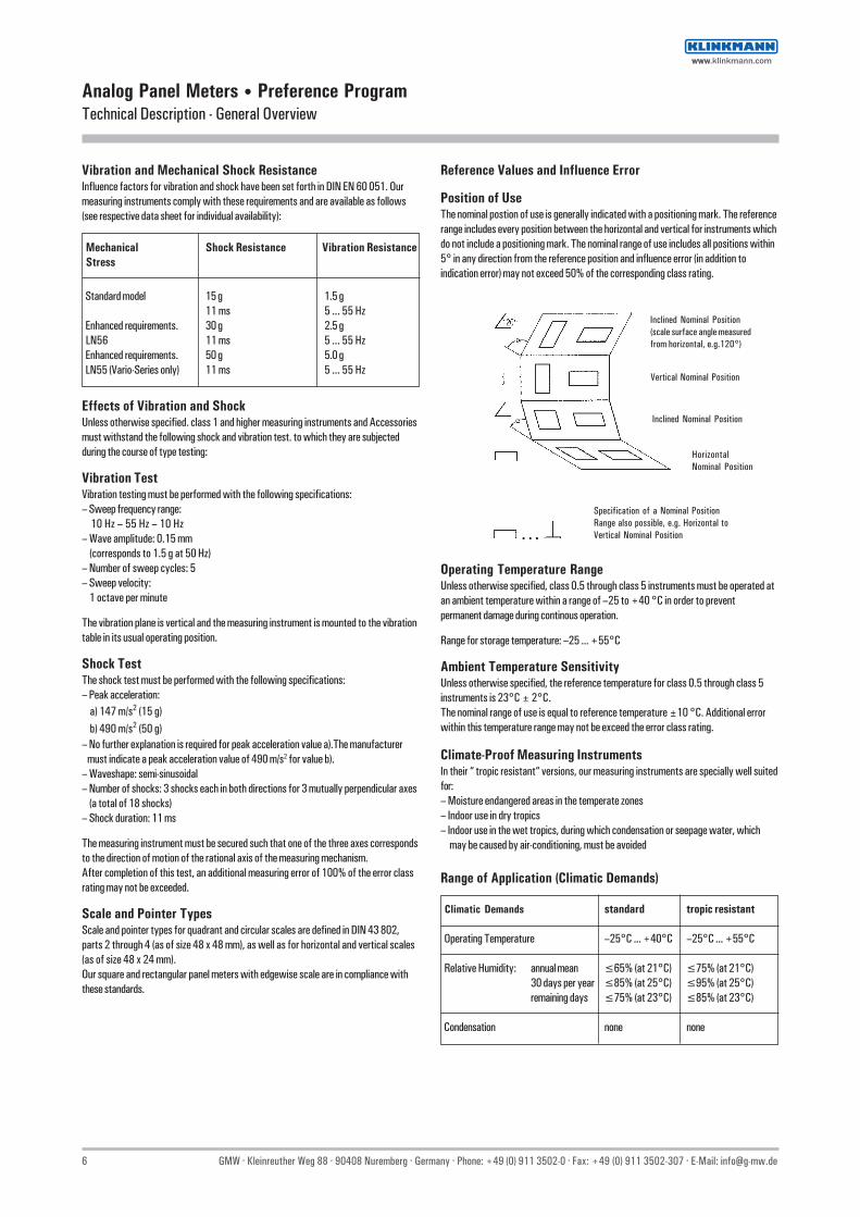
Reference Values and Influence Error
Position of UseThe nominal postion of use is generally indicated with a positioning mark. The referencerange includes every position between the horizontal and vertical for instruments whichdo not include a positioning mark. The nominal range of use includes all positions within5° in any direction from the reference position and influence error (in addition toindication error) may not exceed 50% of the corresponding class rating.
Operating Temperature RangeUnless otherwise specified, class 0.5 through class 5 instruments must be operated atan ambient temperature within a range of –25 to +40 °C in order to preventpermanent damage during continous operation.
Range for storage temperature: –25 ... +55°C
Ambient Temperature SensitivityUnless otherwise specified, the reference temperature for class 0.5 through class 5instruments is 23°C ± 2°C.The nominal range of use is equal to reference temperature ±10 °C. Additional errorwithin this temperature range may not be exceed the error class rating.
Inclined Nominal Position
HorizontalNominal Position
Vertical Nominal Position
Inclined Nominal Position(scale surface angle measuredfrom horizontal, e.g.120°)
Specification of a Nominal PositionRange also possible, e.g. Horizontal toVertical Nominal Position
wwwwww.klinkmann.com

GMW · Kleinreuther Weg 88 · 90408 Nuremberg · Germany · Phone: +49 (0) 911 3502-0 · Fax: +49 (0) 911 3502-307 · E-Mail: [email protected] 7
Basic Series • Square Panel MetersFeatures – Benefits
• Worldwide sales and service
• All panel meters can be supplied ex stock1)
Shunt resistors without protective cover (nominal current up to 1.5 kA)ASK 31.3 / ASK 412.4 current transformers (Class 1. 50-60 Hz)1) “Conditions of delivery for manufactures and performances of electrical industry“ are applied
• Moving-iron panel meters: lower measuring range value equal to 20% of upper measuring range value
• Power meters, power factor meters and frequency meters include built in electronic convertersAllows for precise power measurement even for 3-phase four-wire systems with unbalanced load
• Interchangeable scales for all panel metersScale replacement is quick and simple with no loss of accuracy
• Interchangeable front frame and windows for all panel meters
• Anti-glare glass and terminal cover is included as standard equipment with all panel metersBack of hand and finger contact safety in accordance with BGV A3
• Screw terminals with self–lifting terminal clips for all panel meters,screws can be turned with cross–head or standard screw drivers
wwwwww.klinkmann.com
8 GMW · Kleinreuther Weg 88 · 90408 Nuremberg · Germany · Phone: +49 (0) 911 3502-0 · Fax: +49 (0) 911 3502-307 · E-Mail: [email protected]
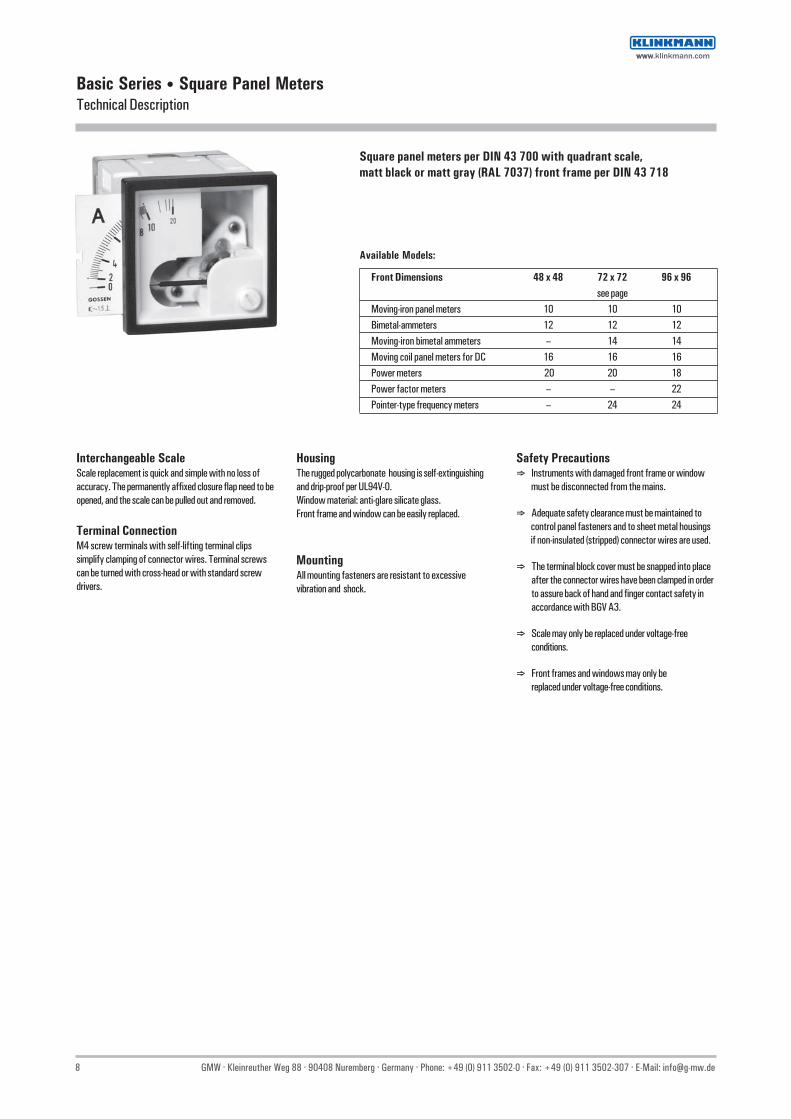
Front Dimensions 48 x 48 72 x 72 96 x 96see page
Moving-iron panel meters 10 10 10Bimetal-ammeters 12 12 12Moving-iron bimetal ammeters – 14 14Moving coil panel meters for DC 16 16 16Power meters 20 20 18Power factor meters – – 22Pointer-type frequency meters – 24 24
Basic Series • Square Panel MetersTechnical Description
Interchangeable ScaleScale replacement is quick and simple with no loss ofaccuracy. The permanently affixed closure flap need to beopened, and the scale can be pulled out and removed.
Terminal ConnectionM4 screw terminals with self-lifting terminal clipssimplify clamping of connector wires. Terminal screwscan be turned with cross-head or with standard screwdrivers.
HousingThe rugged polycarbonate housing is self-extinguishingand drip-proof per UL94V-0.Window material: anti-glare silicate glass.Front frame and window can be easily replaced.
MountingAll mounting fasteners are resistant to excessivevibration and shock.
Safety Precautions⇒ Instruments with damaged front frame or window must be disconnected from the mains.
⇒ Adequate safety clearance must be maintained to control panel fasteners and to sheet metal housings if non-insulated (stripped) connector wires are used.
⇒ The terminal block cover must be snapped into placeafter the connector wires have been clamped in orderto assure back of hand and finger contact safety inaccordance with BGV A3.
⇒ Scale may only be replaced under voltage-freeconditions.
⇒ Front frames and windows may only bereplaced under voltage-free conditions.
Square panel meters per DIN 43 700 with quadrant scale,matt black or matt gray (RAL 7037) front frame per DIN 43 718
Available Models:
wwwwww.klinkmann.com

GMW · Kleinreuther Weg 88 · 90408 Nuremberg · Germany · Phone: +49 (0) 911 3502-0 · Fax: +49 (0) 911 3502-307 · E-Mail: [email protected] 9
Basic Series • Square Panel MetersTechnical Description - Measuring Systems
See individual technical data for technical description of frequency meters, active and reactive power meters and power factor meters
Moving-Coil Movement Moving-Iron Movement Bimetal Movement
Application Measurement of direct current or direct Measurement of alternating current or Measurement of alternating current andvoltage alternating voltage direct currentPrecision measurement of average value True RMS measurement True RMS measurement
Power and power factor cos phi The integrated slave pointer indicates thehighest attained value
Bearings Rugged pivot bearings Rugged pivot bearings Rugged bronze bearingswith spring-loaded jewels with spring-loaded jewels
Damping Eddy-current damping Viscous damping Thermal, time-delayed, for display of meaneffective value
• Overshoot ≤ 15 % of scale length ≤ 15 % of scale length• Response Time ≤ 1 s per DIN EN 60 051-1 ≤ 2 s per DIN EN 60 051-1 15 min.. alternatively 8 min.
Reference Conditions
• Frequency 45 Hz ... 65 Hz 45 Hz ... 65 Hz 45 Hz ... 65 Hz
Nominal Range of Use
• Frequency Ammeter: 45 Hz ... 65 Hz ≤ 400 HzVoltmeter: 45 Hz ... 65 Hz
Scale Characterictics nearly linear Lower measuring range value is approx. 20%of upper measuring range value.Ammeters with double overload scale
Measuring Range see technical data see technical data see technical data
Overload Capacity
• Continous 1.2 x rated value 1.2 x rated value 1.2 x rated value• Short Term: Current Measurement 10 x rated value, 1 s 10 x IN , 1 s (Imax = 50 A) 10 x IN , 1 s (Imax = 50 A)
Voltage Measurement 2 x UN, 5 s 2 x UN, 5 s
Connection Screws M4 Screws M4 Screws M4Bolt M6 if measuring input >15 A and ≤ 40 A Bolt M6 if measuring input >15 A and ≤ 40 A
Bolt M8 if measuring input >40 A and ≤ 60 A
Power Consumption see technical data Ammeters: approx. 0.65 VA (5 A) 1 A : ≤ 1.5 VAVoltmeters: approx. 2.5 VA (250 V) 5 A : ≤ 2.5 VA
Please request data sheets if requiredfor products and options not included in this catalog.
wwwwww.klinkmann.com
10 GMW · Kleinreuther Weg 88 · 90408 Nuremberg · Germany · Phone: +49 (0) 911 3502-0 · Fax: +49 (0) 911 3502-307 · E-Mail: [email protected]
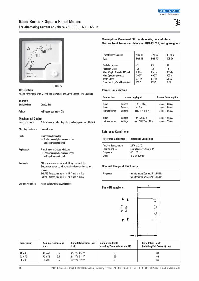
Basic Series • Square Panel MetersFor Alternating Current or Voltage 45 ... 50 ... 60 ... 65 Hz
Moving-Iron Movement, 90° scale white, imprint blackNarrow front frame matt black per DIN 43 718, anti-glare glass
Front Dimensions mm 48 x 48 72 x 72 96 x 96 Type EQB 48 EQB 72 EQB 96
Scale length mm 42 63 97 Accuracy Class 1.5 1.5 1.5 Max. Weight (Standard Model) 0.1 kg 0.2 kg 0.25 kg Max. Operating Voltage 300 V 600 V 600 V Test Voltage 3.5 kV 5.8 kV 5.8 kV Front Housing-Panel Protection IP 52 IP 52 IP 52
DescriptionAnalog Panel Meter with Moving-Iron Movement and Spring-Loaded Pivot Bearings
DisplayScale Division Coarse-fine
Pointer Knife-edge pointer per DIN
Mechanical DesignHousing Material Polycarbonate, self-extinguishing and drip-proof per UL94V-0
Mounting Fasteners Screw Clamp
Scale Interchangeable scales⇒ Scales may only be replaced under
voltage-free conditions!
Replaceable Front frames and glass windows⇒ Scales may only be replaced under
voltage-free conditions!
Terminals M4 screw terminals with self-lifting terminal clips.Screws can be turned with cross-head or standard screwdrivers.Bolt M6 if measuring input > 15 A and ≤ 40 ABolt M8 if measuring input > 40 A and ≤ 60 A
Contact Protection Finger-safe terminal cover included
Power Consumption
Connection Measuring Input Power Consumption
direct Current 1 A ... 10 A approx. 0.6 VA direct Current ≥15 A approx. 0.8 VA to transformer Current sec.: 1 A or 5 A approx. 0.6 VA
direct Voltage 10 V ... 600 V approx. 2.5 VA to transformer Voltage sec.: 100 V or 110 V approx. 2.5 VA
Reference Conditions
Reference Quantities Reference Conditions
Ambient Temperature 23°C ± 2°C Position of Use control panel vertical ± 1° Frequency 45 ... 65 Hz Other DIN EN 60051
Nominal Range of Use Limits
Frequency for alternating Current 45 ... 65 Hzfor alternating Voltage 45 ... 65 Hz
1a x
a2
f
l x
l
th
12
Basic Dimensions
EQB 72
Front in mm Nominal Dimensions Cutout Dimensions, mm Installation Depth Installation Deptha1 x a2 h I1 x I2 Including Terminals (t), mm M4 Including Full Cover (f), mm
48 x 48 48 x 48 5.5 45+0.6 x 45+0.6 53 66 72 x 72 72 x 72 5.5 68+0.7 x 68+0.7 53 66 96 x 96 96 x 96 5.5 92+0.8 x 92+0.8 53 66
wwwwww.klinkmann.com

GMW · Kleinreuther Weg 88 · 90408 Nuremberg · Germany · Phone: +49 (0) 911 3502-0 · Fax: +49 (0) 911 3502-307 · E-Mail: [email protected] 11
Moving-iron movement, 90° scale white, imprint blackNarrow front frame matt black per DIN 43 718, anti-glare glass
Type EQB 48 EQB 72 EQB 96Range Scale 1) Order No. ⇓ ⇓ ⇓
1.5 / 3 A 1.5 / 3 A 48015 30000 B 72015 30000 B 96015 30000 B2.5 / 5 A 2.5 / 5 A 48025 50000 B 72025 50000 B —4 / 8 A 4 / 8 A 48048 00000 B 72048 00000 B —6 / 12 A 6 / 12 A 48612 00000 B 72612 00000 B 96612 00000 B10 / 20 A 10 / 20 A 48102 00000 B 72102 00000 B 96102 00000 B15 / 30 A 15 / 30 A 48153 00000 B 72153 00000 B 96153 00000 B20 / 40 A 20 / 40 A — 72204 00000 B —25 / 50 A 25 / 50 A 48255 00000 B 72255 00000 B 96255 00000 B30 / 60 A 30 / 60 A — 72306 00000 B —40 / 80 A 40 / 80 A — 72408 00000 B 96408 00000 B50 / 100 A 50 / 100 A — 72501 00000 B —60 / 120 A 60 / 120 A — 72601 20000 B 96601 20000 B
1 / 2 A 0 – 50 / 100 A 48125 01000 B 72120 50100 B 96120 50100 B1 / 2 A 0 – 60 / 120 A 48126 01200 B 72120 60120 B 96120 60120 B1 / 2 A 0 – 100 / 200 A 48121 00200 B 72120 10020 B 96120 10020 B1 / 2 A 0 – 150 / 300 A 48121 50300 B 72120 15030 B 96120 15030 B1 / 2 A 0 – 200 / 400 A 48122 00400 B 72120 20040 B 96120 20040 B1 / 2 A 0 – 250 / 500 A 48122 50500 B 72120 25050 B 96120 25050 B1 / 2 A 0 – 400 / 800 A 48124 00800 B 72120 40080 B 96120 40080 B1 / 2 A 0 – 600 / 1200 A 48126 00120 B 72120 60012 B 96120 60012 B1 / 2 A 0 – 800 / 1600 A 48128 00160 B 72120 80016 B 96120 80016 B1 / 2 A 0 – 1000 / 2000 A 48121 00020 B 72120 10002 B 96120 10002 B1 / 2 A 0 – 1200 / 2400 A 48121 20024 B 72120 12002 B 96120 12002 B1 / 2 A 0 – 1500 / 3000 A 48121 50030 B 72120 15003 B 96120 15003 B1 / 2 A 0 – 2000 / 4000 A 48122 00040 B 72120 20004 B 96120 20004 B
5 / 10 A 0 – 50 / 100 A 48510 50100 B 72510 50100 B 96510 50100 B5 / 10 A 0 – 60 / 120 A 48510 60120 B 72510 60120 B 96510 60120 B5 / 10 A 0 – 100 / 200 A 48510 10020 B 72510 10020 B 96510 10020 B5 / 10 A 0 – 150 / 300 A 48510 15030 B 72510 15030 B 96510 15030 B5 / 10 A 0 – 200 / 400 A 48510 20040 B 72510 20040 B 96510 20040 B5 / 10 A 0 – 250 / 500 A 48510 25050 B 72510 25050 B 96510 25050 B5 / 10 A 0 – 400 / 800 A 48510 40080 B 72510 40080 B 96510 40080 B5 / 10 A 0 – 600 / 1200 A 48510 60012 B 72510 60012 B 96510 60012 B5 / 10 A 0 – 800 / 1600 A 48510 80016 B 72510 80016 B 96510 80016 B5 / 10 A 0 – 1000 / 2000 A 48510 10002 B 72510 10002 B 96510 10002 B5 / 10 A 0 – 1200 / 2400 A 48510 12002 B 72510 12002 B 96510 12002 B5 / 10 A 0 – 1500 / 3000 A 48510 15003 B 72510 15003 B 96510 15003 B5 / 10 A 0 – 2000 / 4000 A 48510 20004 B 72510 20004 B 96510 20004 B
10 V 10 V — 72000 00010 B 96000 00010 B 60 V 60 V — 72000 00060 B 96000 00060 B100 V 100 V 48000 00100 B 72000 00100 B 96100 00000 B120 V 120 V — 72120 00000 B 96120 00000 B150 V 150 V 48150 00000 B — —250 V 250 V 48250 00000 B 72250 00000 B 96250 00000 B500 V 500 V 48500 00000 B 2) 72500 00000 B 96500 00000 B600 V 600 V — 72600 00000 B 96600 00000 B
Basic Series • Square Panel MetersFor Alternating Current or Voltage 45 ... 50 ... 60 ... 65 Hz
1) Specify unlisted scales in clear text2) Max. operating voltage above earth 300 V
Ammeters without overload scale on request.
Ammeters with overload scale on request for 1.2 times, three, five or six times rated current.
wwwwww.klinkmann.com

12 GMW · Kleinreuther Weg 88 · 90408 Nuremberg · Germany · Phone: +49 (0) 911 3502-0 · Fax: +49 (0) 911 3502-307 · E-Mail: [email protected]
Basic Series • Square Panel MetersFor Alternating Current
Bimetal-movement, 90° scale white, imprint blackNarrow front frame matt black per DIN 43 718, anti-glare glass
Front Dimensions mm 48 x 48 72 x 72 96 x 96 Type MQB 48 MQB 72 MQB 96
Scale Length mm 42 63 97 Accuracy Class 3 3 3 Max. Weight (standrad model) 0.1 kg 0.2 kg 0.25 kg Max. Operating Voltage 300 V 600 V 600 V Test Voltage 3.5 kV 5.8 kV 5.8 kV Front Housing Panel Protection IP 52 IP 52 IP 52
DescriptionAnalog Panel Meter with Bimetal Movement
DisplayScale Division Coarse-fine
Pointer Beam pointer with knife-edgeRed slave pointer for display of maximum valueReset button for slave pointer can be locked
Mechanical DesignHousing Material Polycarbonate, self extinguishing and drip-proof per UL94V-0
Mounting Fasteners Screw Clamp
Scale Interchangeable Scales⇒ Scales may only be replaced under
voltage-free conditions!
Replaceable Front frames and glass windows⇒ May only be replaced under
voltage-free conditions!
Terminals M4 screw terminals with self-lifting terminal clips.Screws can be turned with cross-head or standard screwdrivers.
Contact Protection Finger-safe terminal cover included
Reference Conditions
Reference Quantities Reference Conditions
Ambient Temperature 23°C ± 2°C Position of Use control panel vertical ± 1° Other DIN EN 60051
Basic Dimensions
MQB 72
Front in mm Nominal Dimensions Cutout Dimensions, mm Installation Depth Installation Deptha1 x a2 h I1 x I2 Including Terminals (t), mm M4 Including Full Cover (f), mm
48 x 48 48 x 48 5.5 45+0.6 x 45+0.6 53 66 72 x 72 72 x 72 5.5 68+0.7 x 68+0.7 53 66 96 x 96 96 x 96 5.5 92+0.8 x 92+0.8 53 66
1a x
a2
f
l x
l
th
12
Power Consumption
Connection Measuring Input Power Consumption
to transformer Current sec.: 1 A or 5 A approx. 2.2 VA
wwwwww.klinkmann.com

GMW · Kleinreuther Weg 88 · 90408 Nuremberg · Germany · Phone: +49 (0) 911 3502-0 · Fax: +49 (0) 911 3502-307 · E-Mail: [email protected] 13
Basic Series • Square Panel MetersFor Alternating Current
Bimetal-movement, 90° scale white, imprint blackNarrow front frame matt black per DIN 43 718, anti-glare glass
Type MQB 48 MQB 72 MQB 96Range Scale 1) Order No. ⇓ ⇓ ⇓
5 / 6 A, 8 or 15 min. 0 – 50 / 60 A5 / 6 A, 8 or 15 min. 0 – 60 / 72 A5 / 6 A, 8 or 15 min. 0 – 100 / 120 A5 / 6 A, 8 or 15 min. 0 – 150 / 180 A5 / 6 A, 8 or 15 min. 0 – 200 / 240 A5 / 6 A, 8 or 15 min. 0 – 250 / 300 A5 / 6 A, 8 or 15 min. 0 – 400 / 480 A5 / 6 A, 8 or 15 min. 0 – 600 / 720 A5 / 6 A, 8 or 15 min. 0 – 800 / 960 A5 / 6 A, 8 or 15 min. 0 – 1000 / 1200 A5 / 6 A, 8 or 15 min. 0 – 1200 / 1440 A5 / 6 A, 8 or 15 min. 0 – 1500 / 1800 A
1 / 1.2 A, 8 or 15 min. 0 – 50 / 60 A1 / 1.2 A, 8 or 15 min. 0 – 60 / 72 A1 / 1.2 A, 8 or 15 min. 0 – 100 / 120 A1 / 1.2 A, 8 or 15 min. 0 – 150 / 180 A1 / 1.2 A, 8 or 15 min. 0 – 200 / 240 A1 / 1.2 A, 8 or 15 min. 0 – 250 / 300 A1 / 1.2 A, 8 or 15 min. 0 – 400 / 480 A1 / 1.2 A, 8 or 15 min. 0 – 600 / 720 A1 / 1.2 A, 8 or 15 min. 0 – 800 / 960 A1 / 1.2 A, 8 or 15 min. 0 – 1000 / 1200 A1 / 1.2 A, 8 or 15 min. 0 – 1200 / 1440 A1 / 1.2 A, 8 or 15 min. 0 – 1500 / 1800 A
All panel meters available with the following configurations:Front Dimensions: 48 x 48, 72 x 72, 96 x 96Connected to 1 / 1.2 A or 5 / 6 A transformer
Response Time: 8 min. or 15 min.Scale as requested
Please note ordering example below:
Ordering Example:
Type Text for purchase order: MQB 96 Range 5 / 6 A, Scale 0 – 100 / 120 A, 15 min.
1) Specify unlisted scales in clear text
wwwwww.klinkmann.com

14 GMW · Kleinreuther Weg 88 · 90408 Nuremberg · Germany · Phone: +49 (0) 911 3502-0 · Fax: +49 (0) 911 3502-307 · E-Mail: [email protected]
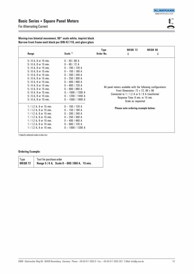
Basic Series • Square Panel MetersFor Alternating Current
Moving-iron bimetal movement, 90° scale white, imprint blackNarrow front frame matt black per DIN 43 718, anti-glare glass
Front Dimensions mm 72 x 72 96 x 96 Type MEQB 72 MEQB 96
Scale Length mm Moving-Iron Movement 63 97Bimetal-Movement 42 72
Accuracy Class Moving-Iron / Bimetal Movement 1.5 / 3 1.5 / 3 Max. Weight (standard model) 0.2 kg 0.29 kg Max. Operating Voltage 600 V 600 V Test Voltage 5.8 kV 5.8 kV Front Housing-Panel Protection IP 52 IP 52
DescriptionAnalog Panel Meter with Moving-Iron and Bimetal Movements
DisplayScale Division Coarse-fine
Pointer Beam pointer with knife-edgeRed slave pointer for display of maximum valueReset button for slave pointer can be locked
Mechanical DesignHousing Material Polycarbonate, self-extinguishing and drip-proof per UL94V-0
Mounting Fasteners Screw Clamp
Scale Interchangeable scales⇒ Scales may only be replaced under voltage-free conditions!
Replaceable Front frames and glass windows⇒ May only be replaced under voltage-free conditions!
Terminals M4 screw terminals with self lifting terminal clips.Screws can be turned with cross-head or standard screwdrivers.
Contact Protection Finger-safe terminal cover included
Reference Conditions
Reference Quantities Reference Conditions
Ambient Temperature 23°C ± 2°C Position of Use control panel vertical ± 1° Other DIN EN 60051
Basic Dimensions
Front in mm Nominal Dimensions Cutout Dimensions, mm Installation Depth Installation Deptha1 x a2 h I1 x I2 Including Terminals (t), mmM4 Including Full Cover (f), mm
72 x 72 72 x 72 5.5 68+0.7 x 68+0.7 53 66 96 x 96 96 x 96 5.5 92+0.8 x 92+0.8 53 66
MEQB 96
1a x
a2
f
l x
l
th
12
Power Consumption
Connection Measuring input Power Consumption
to transformer Current sec.: 1 A or 5 A approx. 2.6 VA
wwwwww.klinkmann.com
GMW · Kleinreuther Weg 88 · 90408 Nuremberg · Germany · Phone: +49 (0) 911 3502-0 · Fax: +49 (0) 911 3502-307 · E-Mail: [email protected] 15
Basic Series • Square Panel MetersFor Alternating Current
Moving-iron bimetal movement, 90° scale white, imprint blackNarrow front frame matt black per DIN 43 718, anti-glare glass
Type MEQB 72 MEQB 96Range Scale 1) Order No. ⇓ ⇓
5 / 6 A, 8 or 15 min. 0 – 50 / 60 A5 / 6 A, 8 or 15 min. 0 – 60 / 72 A5 / 6 A, 8 or 15 min. 0 – 100 / 120 A5 / 6 A, 8 or 15 min. 0 – 150 / 180 A5 / 6 A, 8 or 15 min. 0 – 200 / 240 A5 / 6 A, 8 or 15 min. 0 – 250 / 300 A5 / 6 A, 8 or 15 min. 0 – 400 / 480 A5 / 6 A, 8 or 15 min. 0 – 600 / 720 A5 / 6 A, 8 or 15 min. 0 – 800 / 960 A5 / 6 A, 8 or 15 min. 0 – 1000 / 1200 A5 / 6 A, 8 or 15 min. 0 – 1200 / 1440 A5 / 6 A, 8 or 15 min. 0 – 1500 / 1800 A
1 / 1.2 A, 8 or 15 min. 0 – 100 / 120 A1 / 1.2 A, 8 or 15 min. 0 – 150 / 180 A1 / 1.2 A, 8 or 15 min. 0 – 200 / 240 A1 / 1.2 A, 8 or 15 min. 0 – 250 / 300 A1 / 1.2 A, 8 or 15 min. 0 – 400 / 480 A1 / 1.2 A, 8 or 15 min. 0 – 600 / 720 A1 / 1.2 A, 8 or 15 min. 0 – 1000 / 1200 A
All panel meters available with the following configurations:Front Dimensions: 72 x 72, 96 x 96
Connected to 1 / 1.2 A or 5 / 6 A transformerResponse Time: 8 min. or 15 min.
Scale as requested
Please note ordering example below:
1) Specify unliested scales in clear text
Ordering Example:
Type Text for purchase order MEQB 72 Range 5 / 6 A, Scale 0 – 800 / 960 A, 15 min.
wwwwww.klinkmann.com
16 GMW · Kleinreuther Weg 88 · 90408 Nuremberg · Germany · Phone: +49 (0) 911 3502-0 · Fax: +49 (0) 911 3502-307 · E-Mail: [email protected]
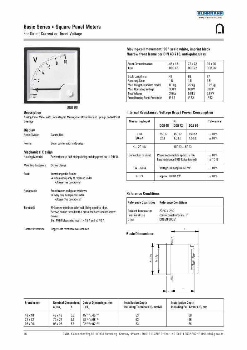
Basic Series • Square Panel MetersFor Direct Current or Direct Voltage
Moving-coil movement, 90° scale white, imprint blackNarrow front frame per DIN 43 718, anti-galre glass
Front Dimensions mm 48 x 48 72 x 72 96 x 96 Type DQB 48 DQB 72 DQB 96
Scale Length mm 42 63 97 Accuracy Class 1.5 1.5 1.5 Max. Weight (standard model) 0.1 kg 0.2 kg 0.25 kg Max. Operating Voltage 300 V 600 V 600 V Test Voltage 3.5 kV 5.8 kV 5.8 kV Front Housing-Panel Protection IP 52 IP 52 IP 52
DescriptionAnalog Panel Meter with Core-Magnet Moving-Coil Movement and Spring-Loaded PivotBearings
DisplayScale Division Coarse-fine
Pointer Beam pointer with knife-edge
Mechanical DesignHousing Material Polycarbonate, self-extinguishing and drip-proof per UL94V-0
Mounting Fasteners Screw Clamp
Scale Interchangeable Scales⇒ Scales may only be replaced under
voltage-free conditions!
Replaceable Front frames and glass windows⇒ May only be replaced under
voltage-free conditions!
Terminals M4 screw terminals with self-lifting terminal clips.Screws can be turned with a cross-head or standard screwdrivers.Bolt M6 if Measuring input > 15 A and ≤ 40 A
Contact Protection Finger-safe terminal cover included
Internal Resistance / Voltage Drop / Power Consumption
Measuring Input Ri ToleranceDQB 48 DQB 72 DQB 96
1 mA 250 Ω 150 Ω 150 Ω ± 10 %20 mA 2 Ω 1.5 Ω 1.5 Ω ± 10 %
4 ... 20 mA 180 Ω ... 60 Ω
Connection to shunt Power consumption approx. 7 mA ± 10 %Lead resistance 0.06 Ω (calibrated) ± 10 %
1 A ... 60 A Voltage Drop approx. 60 mV ± 10 %
≥ 1 V approx. 1000 Ω/ V ± 10 %
Reference Conditions
Reference Quantities Reference Conditions
Ambient Temperature 23°C ± 2°C Position of Use control panel vertical± 1° Other DIN EN 60051
DQB 96
Basic Dimensions
Front in mm Nominal Dimensions Cutout Dimensions, mm Installation Depth Installation Deptha1 x a2 h I1 x I2 Including Terminals (t), mmM4 Including Full Covers (f), mm
48 x 48 48 x 48 5.5 45+0.6 x 45+0.6 53 66 72 x 72 72 x 72 5.5 68+0.7 x 68+0.7 53 66 96 x 96 96 x 96 5.5 92+0.8 x 92+0.8 53 66
1a x
a2
f
l x
l
th
12
wwwwww.klinkmann.com

GMW · Kleinreuther Weg 88 · 90408 Nuremberg · Germany · Phone: +49 (0) 911 3502-0 · Fax: +49 (0) 911 3502-307 · E-Mail: [email protected] 17
Moving-coil movement, 90° scale white, imprint blackNarrow front frame per DIN 43 718, anti-glare glass
Type DQB 48 DQB 72 DQB 96Range Scale 1) Order No. ⇓ ⇓ ⇓
1 mA 0 – 100 % 2) 48010 00000 B 72010 00000 B 96010 00000 B1 – 0 – 1 mA 100 – 0 – 100 % 2) 48101 00000 B 72101 00000 B 96101 00000 B20 mA 0 – 100 % 2) 48200 00000 B 72002 00100 B 96002 00100 B0/4 – 20 mA 0 – 100 % 2) 48420 00000 B 72420 00000 B 96420 00000 B
15 A 15 A — 72015 00000 B 96015 00000 B25 A 25 A — 72025 00000 B 96025 00000 B40 A 40 A — 72040 00000 B 96040 00000 B
Connection to shunt ... A/60 mV 3)
60 mV 0 – 10 A 48006 00010 B 72006 00010 B 96006 00010 B60 mV 0 – 15 A 48006 00015 B 72006 00015 B 96006 00015 B60 mV 0 – 25 A 48006 00025 B 72006 00025 B 96006 00025 B60 mV 0 – 40 A 48006 00040 B 72006 00040 B 96006 00040 B60 mV 0 – 60 A 48006 00060 B 72006 00060 B 96006 00060 B60 mV 0 – 100 A 48006 00100 B 72006 00100 B 96006 00100 B60 mV 0 – 150 A 48006 00150 B 72006 00150 B 96006 00150 B60 mV 0 – 200 A 48006 00200 B 72006 00200 B 96006 00200 B60 mV 0 – 250 A 48006 00250 B 72006 00250 B 96006 00250 B60 mV 0 – 400 A 48006 00400 B 72006 00400 B 96006 00400 B60 mV 0 – 600 A 48006 00600 B 72006 00600 B 96006 00600 B60 mV 0 – 1000 A 48006 01000 B 72006 01000 B 96006 01000 B60 mV 0 – 1200 A 48006 01200 B 72006 01200 B 96006 01200 B60 – 0 – 60 mV 60 – 0 – 60 A 48600 60600 B 72600 60600 B 96600 60600 B60 – 0 – 60 mV 100 – 0 – 100 A 48600 60100 B 72600 60100 B 96600 60100 B
10 V 10 V 48101 01010 B 72001 00000 B 96001 00000 B25 V 25 V 48252 52525 B 72002 50000 B 96002 50000 B40 V 40 V 48404 04040 B 72004 00000 B 96004 00000 B60 V 60 V 48606 06060 B 72006 00000 B 96006 00000 B500 V 500 V — 72050 00000 B 96050 00000 B
Basic Series • Square Panel MetersFor Direct Current or Direct Voltage
1) Specify unlisted scales in clear text2) Scales with special design available for an extra charge3) Connection to shunt ... A/150 mV with measuring range 150 mV or 150 - 0 -150 mV also available (plus extra charge for special measuring range);
Specify in clear text in order designation
wwwwww.klinkmann.com

18 GMW · Kleinreuther Weg 88 · 90408 Nuremberg · Germany · Phone: +49 (0) 911 3502-0 · Fax: +49 (0) 911 3502-307 · E-Mail: [email protected]
Basic Series • Square Panel MetersFor Active Power or Reactive Power
Moving-coil movement, 90° scale white, imprint blackNarrow front frame matt black per DIN 43718, anti-glare glass
Front Dimensions mm 96 x 96 Type DLMQB 96
Scale Length mm 97 Accuracy Class 1.5 Max. Weight (standard model) 0.56 kg Max. Operating Voltage 600 V Test Voltage 5.8 kV Front Housing-Panel Protection IP 52 Input Meter 1 mA
DescriptionAnalog panel meter with core-magnet moving-coil movement and built in powerconverter for active and reactive power.Depending upon type of system and power, the power converter consists of one,two or three multipliers. The multipliers funtion in accordance with theTDM process (time division muliplier). The output signals from the multipliers areadded and fed to the moving coil mechanism.
DisplayScale Division Coarse-fine
Pointer Beam pointer with edge-knife
Mechanical DesignHousing Material Polycarbonate. self-extinguishing and drip-proof per UL94V-0
Mounting Fasteners Screw Clamp
Scale Interchangeable Scales⇒ Scales may only be replaced under voltage-free conditions!
Replaceable Front frames and glass windows⇒ May only be replaced under voltage-free conditions
Terminals M4 screw terminals with self-lifting terminal clips. Screwscan be turned with a cross-head or standard srew drivers.
Contact Protection Finger-safe terminal cover included
Reference Conditions
Reference Quantities Reference Conditions
Ambient Temperature 23°C ± 2°C Position of Use control panel vertical ±1° Frequency 50 Hz ±2 % Current Components 20 ... 120% of rated value Voltage Components 98 ... 102% of rated value Warm-Up Time ≥ 5 min. Other DIN EN 60051
Basic Dimensions
DLMQB 96
Front in mm Nominal Dimensons Cutout Dimensions, mm Installation Depth Installation Deptha1 x a2 h I1 x I2 lncluding Terminals (t), mm M4 Including Full Covers (f), mm
96 x 96 96 x 96 5.5 92+0.8 x 92+0.8 117 126
Power Consumption
Connection Power Consumption
Current Path approx. 0.2 VA Voltage Path ≤ 4.3 VA
wwwwww.klinkmann.com

GMW · Kleinreuther Weg 88 · 90408 Nuremberg · Germany · Phone: +49 (0) 911 3502-0 · Fax: +49 (0) 911 3502-307 · E-Mail: [email protected] 19
Basic Series • Square Panel MetersFor Active Power or Reactive Power
Moving-coil movement, 90° scale white, imprint blackNarrow front frame matt black per DIN 43 718, anti-glare glass
Type Oder No. Front Dimensions 96 x 96 mm
DLMQB 96 – P1 W 55004 73100 BDLMQB 96 – P3 Wg 55004 73110 BDLMQB 96 – P3 Wu 55004 73120 BDLMQB 96 – P4 Wg 55004 73130 BDLMQB 96 – P4 Wu 55004 73140 BDLMQB 96 – P1 B 55004 73150 BDLMQB 96 – P3 Bg 55004 73160 BDLMQB 96 – P3 Bu 55004 73170 BDLMQB 96 – P4 Bg 55004 73180 BDLMQB 96 – P4 Bu 55004 73190 B
Ordering Example:
DLMQB 96 P4 Wu 0–60 kW 400 V 100/5 A(Bu)
TypePower 4-WireUnbalanced Load Active Power(Unbalanced Load Reactive Power)RangeNominal VoltageTransformer
DLMQB 96
Notes concerning the Determination of Measuring Ranges
The upper measuring range should be a standard value per DIN 43 701: 1 — 1.2 — 1.5 — 2 — 2.5 — 3 — 4 — 5 — 6 — 7.5 — 8 and correspondingpowers of ten. The upper measuring range value must lie within a range of 0.5 to 1.2 times apparent power.Apparent power PS is calculated from the primary values from the current and voltage transformers:
• Single-Phase AC PS = U x I• Three Phase PS = U x I x √3
where U equals phase-to-phase voltage.
wwwwww.klinkmann.com

20 GMW · Kleinreuther Weg 88 · 90408 Nuremberg · Germany · Phone: +49 (0) 911 3502-0 · Fax: +49 (0) 911 3502-307 · E-Mail: [email protected]
Basic Series • Square Panel MeterFor Active Power or Reactive Power
Moving-coil movement, 90° scale white, imprint blackNarrow front frame matt black per DIN 43718, anti-glare glass
Front Dimensions mm 48 x 48 72 x 72 96 x 96 Type DQB 48 DQB 72 DQB 96
Scale Length mm 42 63 97 Accuracy Class 1.5 1.5 1.5 Max. Weight (standard model) 0.1 kg 0.2 kg 0.25 kg Max. Operating Voltage 300 V 600 V 600 V Test Voltage 3.5 kV 5.8 kV 5.8 kV Front Housing-Panel Protection IP 52 IP 52 IP 52 Input Meter 1 mA 1 mA 1 mA
DescriptionAnalog panel meter with 1mA core-magnet moving-coil movement and separatemeasuring converter for active and reactive power in a separate housing.Depending upon type of system and power the measuring converter consits of one, twoor three mulitpliers. The multipliers function in accordance with the TDM process (timedivision multiplier). The output signals from the multipliers are added and fed to themoving coil mechanism.
DisplayScale Division Coarse-fine
Pointer Beam pointer with edge-knife
Mechanical DesignHousing Material Polycarbonate, self-extinguishing and drip-proof per UL94V-0
Mounting Fasteners Screw clamp
Scale Interchangeable scales⇒ Scales may only be replaced under voltage-free conditions!
Replaceable Front frames and glass windows⇒ May only be replaced under voltage-free conditions!
Terminals M4 screw terminals with self-lifting terminal clips. Screwscan be turned with a cross-head or standard srew drivers
Contact Protection Finger-safe terminal cover included
Reference Conditions
Reference Quantities Reference Conditions
Ambient Temperature 23°C ± 2°C Position of Use control panel vertical ±1° Frequency 50 Hz ±2 % Current Components 20 ... 120% of rated value Voltage Components 98 ... 102% of rated value Warm-Up Time ≥ 5 min. Other DIN EN 60051
Basic Dimensions
DQB 72
Front in mm Nominal Dimensons Cutout Dimensions, mm Installation Depth Installation Deptha1 x a2 h I1 x I2 lncluding Terminals (t), mm M4 Including Full Covers (f)mm
48 x 48 48 x 48 5.5 45+0.6 x 45+0.6 53 66 72 x 72 72 x 72 5.5 68+0.7 x 68+0.7 53 66 96 x 96 96 x 96 5.5 92+0.8 x 92+0.8 53 66
1a x
a2
f
l x
l
th
12
Power Consumption
Connection Power Consumption
Current Path approx. 0.2 VA Voltage Path ≤ 4.3 VA
wwwwww.klinkmann.com
GMW · Kleinreuther Weg 88 · 90408 Nuremberg · Germany · Phone: +49 (0) 911 3502-0 · Fax: +49 (0) 911 3502-307 · E-Mail: [email protected] 21
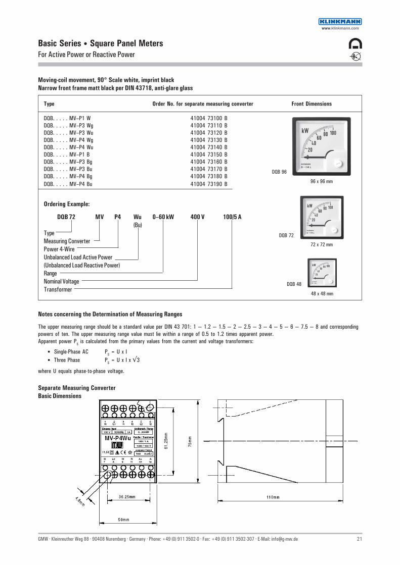
Basic Series • Square Panel MetersFor Active Power or Reactive Power
Separate Measuring ConverterBasic Dimensions
Moving-coil movement, 90° Scale white, imprint blackNarrow front frame matt black per DIN 43718, anti-glare glass
Type Order No. for separate measuring converter Front Dimensions
DQB. . . . . MV–P1 W 41004 73100 BDQB. . . . . MV–P3 Wg 41004 73110 BDQB. . . . . MV–P3 Wu 41004 73120 BDQB. . . . . MV–P4 Wg 41004 73130 BDQB. . . . . MV–P4 Wu 41004 73140 BDQB. . . . . MV–P1 B 41004 73150 BDQB. . . . . MV–P3 Bg 41004 73160 BDQB. . . . . MV–P3 Bu 41004 73170 BDQB. . . . . MV–P4 Bg 41004 73180 BDQB. . . . . MV–P4 Bu 41004 73190 B
Ordering Example:
DQB 72 MV P4 Wu 0–60 kW 400 V 100/5 A(Bu)
TypeMeasuring ConverterPower 4-WireUnbalanced Load Active Power(Unbalanced Load Reactive Power)RangeNominal VoltageTransformer
96 x 96 mm
72 x 72 mm
48 x 48 mm
DQB 72
DQB 48
DQB 96
Notes concerning the Determination of Measuring Ranges
The upper measuring range should be a standard value per DIN 43 701: 1 — 1.2 — 1.5 — 2 — 2.5 — 3 — 4 — 5 — 6 — 7.5 — 8 and correspondingpowers of ten. The upper measuring range value must lie within a range of 0.5 to 1.2 times apparent power.Apparent power PS is calculated from the primary values from the current and voltage transformers:
• Single-Phase AC PS = U x I• Three Phase PS = U x I x √3
where U equals phase-to-phase voltage.
wwwwww.klinkmann.com
22 GMW · Kleinreuther Weg 88 · 90408 Nuremberg · Germany · Phone: +49 (0) 911 3502-0 · Fax: +49 (0) 911 3502-307 · E-Mail: [email protected]
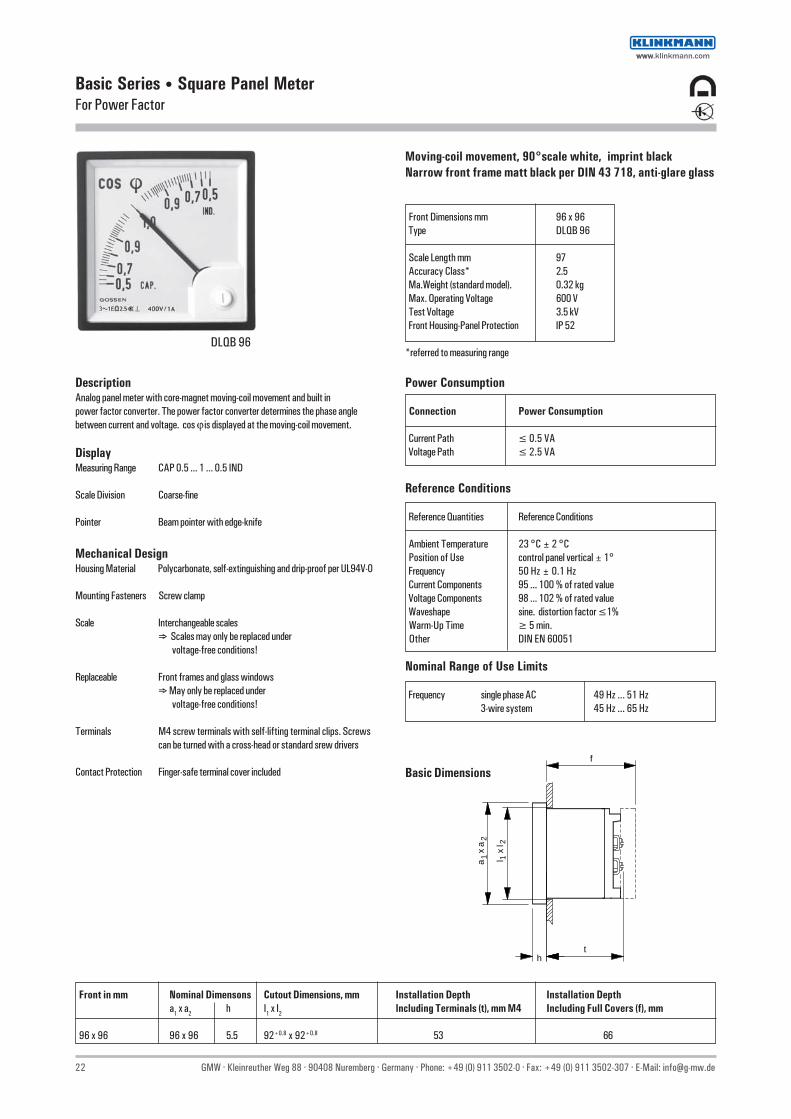
Basic Series • Square Panel MeterFor Power Factor
Moving-coil movement, 90°scale white, imprint blackNarrow front frame matt black per DIN 43 718, anti-glare glass
Front Dimensions mm 96 x 96 Type DLQB 96
Scale Length mm 97 Accuracy Class* 2.5 Ma.Weight (standard model). 0.32 kg Max. Operating Voltage 600 V Test Voltage 3.5 kV Front Housing-Panel Protection IP 52
*referred to measuring range
DescriptionAnalog panel meter with core-magnet moving-coil movement and built inpower factor converter. The power factor converter determines the phase anglebetween current and voltage. cos ϕ is displayed at the moving-coil movement.
DisplayMeasuring Range CAP 0.5 ... 1 ... 0.5 IND
Scale Division Coarse-fine
Pointer Beam pointer with edge-knife
Reference Conditions
Reference Quantities Reference Conditions
Ambient Temperature 23 °C ± 2 °C Position of Use control panel vertical ± 1° Frequency 50 Hz ± 0.1 Hz Current Components 95 ... 100 % of rated value Voltage Components 98 ... 102 % of rated value Waveshape sine. distortion factor ≤1% Warm-Up Time ≥ 5 min. Other DIN EN 60051
Basic Dimensions
Front in mm Nominal Dimensons Cutout Dimensions, mm Installation Depth Installation Deptha1 x a2 h I1 x I2 lncluding Terminals (t), mm M4 Including Full Covers (f), mm
96 x 96 96 x 96 5.5 92+0.8 x 92+0.8 53 66
Nominal Range of Use Limits
Frequency single phase AC 49 Hz ... 51 Hz3-wire system 45 Hz ... 65 Hz
DLQB 96
1a x
a2
f
l x
l
th
12
Power Consumption
Connection Power Consumption
Current Path ≤ 0.5 VA Voltage Path ≤ 2.5 VA
Mechanical DesignHousing Material Polycarbonate, self-extinguishing and drip-proof per UL94V-0
Mounting Fasteners Screw clamp
Scale Interchangeable scales⇒ Scales may only be replaced under voltage-free conditions!
Replaceable Front frames and glass windows⇒ May only be replaced under voltage-free conditions!
Terminals M4 screw terminals with self-lifting terminal clips. Screwscan be turned with a cross-head or standard srew drivers
Contact Protection Finger-safe terminal cover included
wwwwww.klinkmann.com
GMW · Kleinreuther Weg 88 · 90408 Nuremberg · Germany · Phone: +49 (0) 911 3502-0 · Fax: +49 (0) 911 3502-307 · E-Mail: [email protected] 23
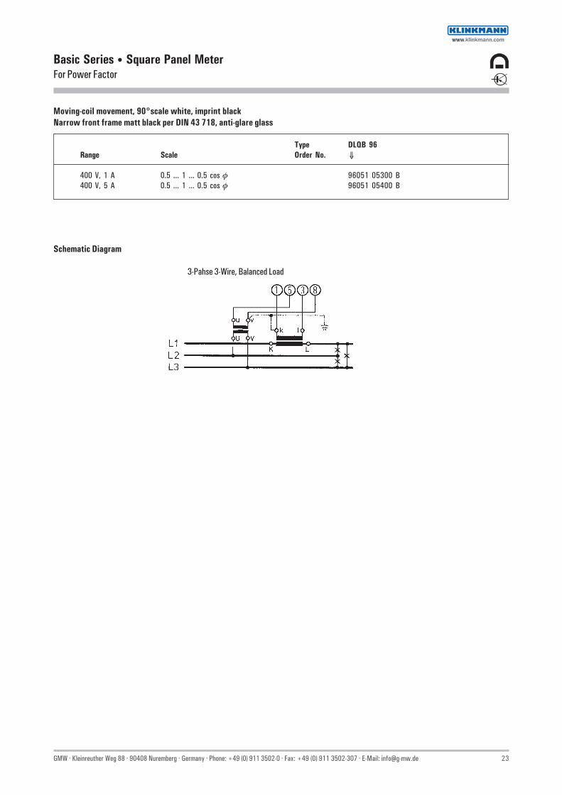
Basic Series • Square Panel MeterFor Power Factor
Schematic Diagram
3-Pahse 3-Wire, Balanced Load
Moving-coil movement, 90°scale white, imprint blackNarrow front frame matt black per DIN 43 718, anti-glare glass
Type DLQB 96Range Scale Order No. ⇓
400 V, 1 A 0.5 ... 1 ... 0.5 cos φ 96051 05300 B400 V, 5 A 0.5 ... 1 ... 0.5 cos φ 96051 05400 B
wwwwww.klinkmann.com
24 GMW · Kleinreuther Weg 88 · 90408 Nuremberg · Germany · Phone: +49 (0) 911 3502-0 · Fax: +49 (0) 911 3502-307 · E-Mail: [email protected]
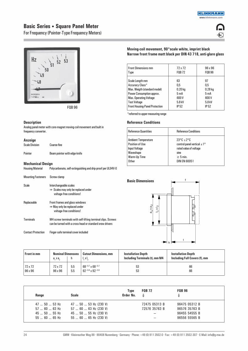
Basic Series • Square Panel MeterFor Frequency (Pointer-Type Frequency Meters)
Moving-coil movement, 90°scale white, imprint blackNarrow front frame matt black per DIN 43 718, anti-glare glass
Front Dimensions mm 72 x 72 96 x 96 Type FQB 72 FQB 96
Scale Length mm 63 97 Accuracy Class* 0,5 0,5 Max. Weigth (standard model) 0.20 kg 0.28 kg Power Consumption approx. 5 mA 5 mA Max. Operating Voltage 600 V 600 V Test Voltage 5.8 kV 5.8 kV Front Housing-Panel Protection IP 52 IP 52
DescriptionAnalog panel meter with core-magnet moving-coil movement and built infrequency converter.
AnzeigeScale Division Coarse-fine
Pointer Beam pointer with edge-knife
Reference Conditions
Reference Quantities Reference Conditions
Ambient Temperature 23°C ±2°C Position of Use control panel vertical ±1° Input Voltage rated value of voltage Waveshape sine Warm-Up Time ≥ 5 min. Other DIN EN 60051
Basic Dimensions
FQB 96
Front in mm Nominal Dimensons Cutout Dimensions, mm Installation Depth Installation Deptha1 x a2 h I1 x I2 lncluding Terminals (t), mm M4 Including Full Covers (f), mm
72 x 72 72 x 72 5.5 68+0.7 x 68+0.7 53 66 96 x 96 96 x 96 5.5 92+0.8 x 92+0.8 53 66
1a x
a2
f
l x
l
th
12
Type FQB 72 FQB 96Range Scale Order No. ⇓ ⇓
47 ... 50 ... 53 Hz 47 ... 50 ... 53 Hz (230 V) 72475 05313 B 96475 05312 B57 ... 60 ... 63 Hz 57 ... 60 ... 63 Hz (230 V) 72576 35763 B 96576 35763 B45 ... 50 ... 55 Hz 45 ... 50 ... 55 Hz (230 V) — 96455 54555 B55 ... 60 ... 65 Hz 55 ... 60 ... 65 Hz (230 V) — 96556 55565 B
Mechanical DesignHousing Material Polycarbonate, self-extinguishing and drip-proof per UL94V-0
Mounting Fasteners Screw clamp
Scale Interchangeable scales⇒ Scales may only be replaced under voltage-free conditions!
Replaceable Front frames and glass windows⇒ May only be replaced under voltage-free conditions!
Terminals M4 screw terminals with self-lifting terminal clips. Screwscan be turned with a cross-head or standard srew drivers
Contact Protection Finger-safe terminal cover included
*referred to upper measuring range
wwwwww.klinkmann.com

GMW · Kleinreuther Weg 88 · 90408 Nuremberg · Germany · Phone: +49 (0) 911 3502-0 · Fax: +49 (0) 911 3502-307 · E-Mail: [email protected] 25
Basic Series • Special Panel MetersFor Alternating Voltage 45 ... 50 ... 60 ... 65 Hz
Moving-iron movement, 90° scale white, imprint blackNarrow front frame per DIN 43 718, anti-glare glass
Dimensions mm 72 x 72 96 x 96 Type EQB 72/U6 EQB 96/U6
Scale Length mm 63 97 Accuracy Class 1.5 1.5 Max. Weight 0.22 kg 0.27 kg Max. Operating Voltage 300 V 300 V Test Voltage 3.5 kV 3.5 kV Front Housing-Panel Protection IP 52 IP 52
DescriptionVoltmeter with selector switch6 Positions without zero positionL1–L3, L2–L3, L1–L2L1–N, L2–N, L3–NAnalog panel meter with moving-iron movement and spring-loaded pivot bearing
DisplayScale Division Coarse-fine
Pointer Knife-edge pointer per DIN
Mechanical DesignHousing Material Polycarbonate, self-extinguishing and drip-proof per UL94V-0
Mounting Fasteners Screw clamp
Replaceable Front frames and glass windows⇒ May only be replaced under voltage-free conditions!
Terminals M4 screw terminals with self-lifting terminal clips. Screws can be turned with a cross-head or standard srew drivers
Contact Protection Finger-safe terminal cover included
Power Consumption
Connection Measuring Input Power Consumption
direct Voltage Phase-Phase 120 V ... 500 V approx. 2.5 VA
Reference Conditions
Reference Quantities Reference Conditions
Ambient Temperature 23°C ± 2°C Position of Use control panel vertical ± 1° Frequency 45 ... 65 Hz Other DIN EN 60051
Nominal Range of Use Limits
Frequency for alternating current 45 ... 65 Hz
Front in mm Nominal Dimensons Cutout Dimensions, mm Installation Depth Installation Depth Selectora1 x a2 h I1 x I2 lncluding Terminals (t), mm M4 Including Full Covers (f), mm Switch (b)
72 x 72 72 x 72 5.5 68+0.7 x 68+0.7 53 66 20 96 x 96 96 x 96 5.5 92+0.8 x 92+0.8 53 66 20
Basic Dimensions
EQB 96/U6
Type EQB 72/U6 EQB 96/U6Range Scale Order No. ⇓ ⇓
120 V 6 kV / 10 kV / 120 V 72120 67212 96120 69612500 V 300 V / 500 V 72500 67250 96500 69650
Schematic Diagram
wwwwww.klinkmann.com

26 GMW · Kleinreuther Weg 88 · 90408 Nuremberg · Germany · Phone: +49 (0) 911 3502-0 · Fax: +49 (0) 911 3502-307 · E-Mail: [email protected]
Power Consumption
Measuring Input Power Consumption
Direct or Alternating Voltage approx. 3-5 VA
Basic Series • Special Panel MetersFor Direct or Alternating Current or Voltage 15 ... 45 ... 65 ... 100 Hz
Moving-iron movement, 105° vertical or horizontal scalewhite, imprint black with grey flange, similar to RAL 7024,Switch 2 A / 250 V and lamp 230 V white
Front Dimensions mm 96 x 48 48 x 96 Type FkN 2 FkN 2
vertical scale* horizontal scale*
Scale Length mm 32 32 Accuracy Class 2.5 2.5 Max. Weigth(standard model) 0.15 kg 0.15 kg Max. Operating Voltage 300 V 300 V Test Voltage 5.8 kV 5.8 kV Front Housing-Panel Protection IP 52 IP 52
FkN 2
DescriptionAnalog panel meter with moving-iron movement
DisplayScale Division WN-division
Pointer Tube pointer
Mechanical DesignHousing Material Thermoplast, white (ABS)
Mounting Fasteners Clamp bolt with milled nut
Scale permanently mounted
Window Plexiglas 7 N, antistatic coating (PMMA)
Terminals Terminal board 2.5 mm2 andM4 - M6 screw terminals
Contact Protection Finger-safe terminal cover included
Reference Conditions
Reference Quantities Reference Conditions
Ambient Temperature 23°C ± 2°C Position of Use control panel vertcial ± 1° Other DIN EN 60051
mounting hole
Cover Bolt can be shortend by breaking
* Specify in clear text
Basic Dimensions
e e1
4 -300V
400 - 600V
up t o
14 A15 - 25 A
26 - 40 A
up t o
14 A15 - 25 A
26 - 40 A
up t o
25 A26 - 40 A
FkN 2 96 48 26.3 21.7 51.7 41 46 31 36.5 42.5 42.5 8 15 91.5 45 92±0,3 45+0,3 M 4 M 5 M 6 18.7 28.5 13 15 9.5
h1g2Type f f1 g1a1 a2 c se3 h2c1 e2 k ro o1c2
wwwwww.klinkmann.com

GMW · Kleinreuther Weg 88 · 90408 Nuremberg · Germany · Phone: +49 (0) 911 3502-0 · Fax: +49 (0) 911 3502-307 · E-Mail: [email protected] 27
Accessories / Spare parts Order No.
Snap-lock cover for FkN 2 N24656
Lamp for FkN 2 220 V AC N07346110 V AC N10816
Switch for FkN 2 48343 86110
Basic Series • Special Panel MetersFor Direct or Alternating Current or Voltage 15 ... 45 ... 65 ... 100 Hz
Type FkN 2 Horizontal Scale1) FkN 2 Vertical Scale1)
Scale 1) Order No. ⇓ ⇓
Direct or Alterating CurrentRange:0 — 100 ... 600 mA 1) in accordance with measuring range N59999 N599991 ... 10 A 1) in accordance with measuring range N59999 N5999915 A 15 A N51301 N5130025 A 25 A N51303 N5130240 A 40 A N51305 N51304
Alternating CurrentConnection to Current Transformer
sec. .../1 A ...1) N51287 N51286Connection to Current Transformer
sec. .../5 A ...1) N51295 N51294
Direct or Alternating VoltageRange:4 ... 150 V 1) in accordance with measuring range N52555 N52555250 V 250 V N51329 N51328
Alternating VoltageConnection to Voltage Transformer
sec. .../100 V ...1) N51325 N51324Connection to Voltage Transformer
sec. .../110 V ...1) N52555 N52555
1) Specify in clear text
Moving-iron movement, 105° vertical or horizontal scale white,imprint black with grey flange, similar to RAL 7024,Switch 2 A / 250 V and lamp 230 V white
wwwwww.klinkmann.com
28 GMW · Kleinreuther Weg 88 · 90408 Nuremberg · Germany · Phone: +49 (0) 911 3502-0 · Fax: +49 (0) 911 3502-307 · E-Mail: [email protected]
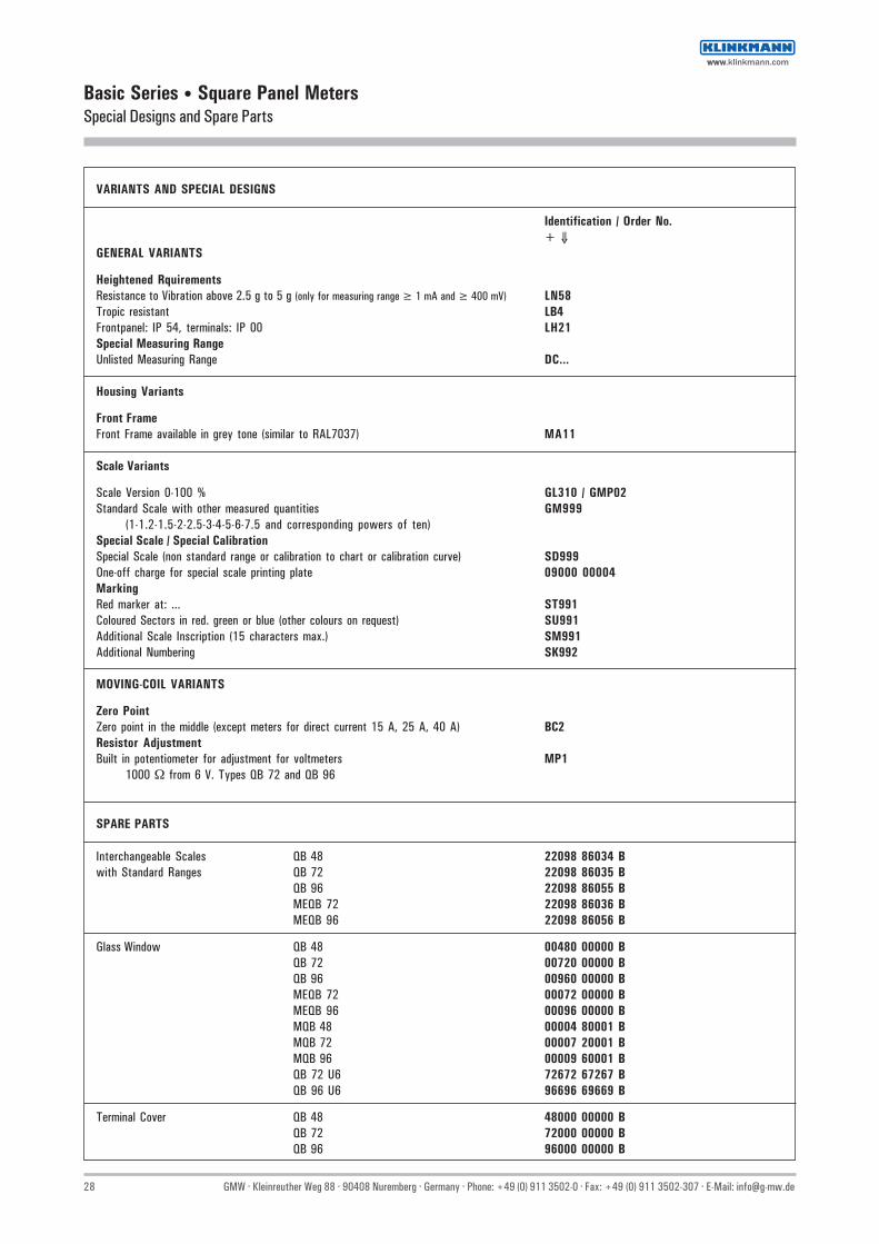
Basic Series • Square Panel MetersSpecial Designs and Spare Parts
VARIANTS AND SPECIAL DESIGNS
Identification / Order No.+ ⇓
GENERAL VARIANTS
Heightened RquirementsResistance to Vibration above 2.5 g to 5 g (only for measuring range ≥ 1 mA and ≥ 400 mV) LN58Tropic resistant LB4Frontpanel: IP 54, terminals: IP 00 LH21Special Measuring RangeUnlisted Measuring Range DC...
Housing Variants
Front FrameFront Frame available in grey tone (similar to RAL7037) MA11
Scale Variants
Scale Version 0-100 % GL310 / GMP02Standard Scale with other measured quantities GM999
(1-1.2-1.5-2-2.5-3-4-5-6-7.5 and corresponding powers of ten)Special Scale / Special CalibrationSpecial Scale (non standard range or calibration to chart or calibration curve) SD999One-off charge for special scale printing plate 09000 00004MarkingRed marker at: ... ST991Coloured Sectors in red. green or blue (other colours on request) SU991Additional Scale Inscription (15 characters max.) SM991Additional Numbering SK992
MOVING-COIL VARIANTS
Zero PointZero point in the middle (except meters for direct current 15 A, 25 A, 40 A) BC2Resistor AdjustmentBuilt in potentiometer for adjustment for voltmeters MP1
1000 Ω from 6 V. Types QB 72 and QB 96
SPARE PARTS
Interchangeable Scales QB 48 22098 86034 Bwith Standard Ranges QB 72 22098 86035 B
QB 96 22098 86055 BMEQB 72 22098 86036 BMEQB 96 22098 86056 B
Glass Window QB 48 00480 00000 BQB 72 00720 00000 BQB 96 00960 00000 BMEQB 72 00072 00000 BMEQB 96 00096 00000 BMQB 48 00004 80001 BMQB 72 00007 20001 BMQB 96 00009 60001 BQB 72 U6 72672 67267 BQB 96 U6 96696 69669 B
Terminal Cover QB 48 48000 00000 BQB 72 72000 00000 BQB 96 96000 00000 B
wwwwww.klinkmann.com

GMW · Kleinreuther Weg 88 · 90408 Nuremberg · Germany · Phone: +49 (0) 911 3502-0 · Fax: +49 (0) 911 3502-307 · E-Mail: [email protected] 29
Basic Series • AccessoriesLow Voltage Current Transformer Class 1
Current Transformer
Current transformers for direct mounting to bus bars or insulated round conductors.Application: indirect measurement of sinusoidal alternating current.
Type ASK 31.3 ASK 412.4
For Bars up to 30 x 10 mm 40 x 12 mm
25.4 x 13 mm 30 x 15 mm
2 x 20 x 10 mm —
For Round Conductors to ∅ 26 mm ∅ 30.5 mm
Rated Primary
Current 50 to 750 A 50 to 1000 A
Class 1 1
Housing Material polycarbonate polycarbonate
Transformer Width 60 mm 70 mm
Weight max. 0.28 kg 0.45 kg
ASK 31.3
Technical Data, Characteristic Values
Polycarbonate housing per UL 94 V-0
Angle bracket and rail Screw Clip Screws with insulated protective cover as standard mount (rail Screw Clip Screws only with plug-on current transformer)
Tightening torque for rail Screw Clip Screws 2 ... 3 Nm
Maximum device voltage Um (effective value) =max. allowable operating voltage 0.72 kV
Rated short-time alternating withstand voltage (effective value) = test voltage 3 kV
Ambient temperature (operating temperature range) – 5 ... 40 °C (no condensation)
Design valid for 40 °C ambient temperature and70 °C bus bar temperature
Rated thermal continous current 1.0 x In
Rated frequency 50 ... 60 Hz
Rated thermal short-time current 60 x In
Insulation class E
Overcurrent limiting factor (FS) FS 5 to 1500 A rated primary currentFS 10 from 1600 A rated primary current
wwwwww.klinkmann.com

30 GMW · Kleinreuther Weg 88 · 90408 Nuremberg · Germany · Phone: +49 (0) 911 3502-0 · Fax: +49 (0) 911 3502-307 · E-Mail: [email protected]
Basic Series • AccessoriesCurrent Transformer Class 1
Type ASK 31.3
Primary Conductor 30 x 10 mm25.4 x 13 mm2 x 20 x 10 mm
Round Conductor ∅ 26 mm
Transformer Width 60 mm
Rated Sec. 5 A Sec. 1 APrimaryCurrent Order No. Order No.
1715V 1715V
A VA + ⇓ + ⇓
50 1.0 0100 110060 1.0 0110 111075 1.5 0120 112080 2.5 0130 1130
100 2.5 0140 1140150 2.5 0150 1150200 5 0160 1160250 10 0170 1170300 10 0180 1180400 10 0190 1190500 10 0200 1200600 10 0210 1210750 10 0220 1220
Accessories: Order No.
Adaptor for 35 mm mounting rail to DIN EN 50 022 1722V9010
Protective cover 1722V9110
Dimensional Drawing
wwwwww.klinkmann.com

GMW · Kleinreuther Weg 88 · 90408 Nuremberg · Germany · Phone: +49 (0) 911 3502-0 · Fax: +49 (0) 911 3502-307 · E-Mail: [email protected] 31
Basic Series • AccessoriesCurrent Transformer Class 1
Typ ASK 412.4
Primary Conductor 40 x 12 mm30 x 15 mm
Round Conductor ∅ 30.5 mm
Transformer Width 70 mm
Rated Sec. 5 A Sec. 1 APrimaryCurrent Order No. Order No.
1716V 1716V
A VA + ⇓ + ⇓
50 1.5 0100 110060 1.5 0110 111075 2.5 0120 112080 2.5 0130 1130
100 3.75 0140 1140150 5 0150 1150200 10 0160 1160250 10 0170 1170300 10 0180 1180400 10 0190 1190500 10 0200 1200600 10 0210 1210750 10 0220 1220800 10 0230 1230
1000 10 0240 1240
Accessories: Order No.
Adaptor for 35 mm mounting rail to DIN EN 50 022 1722V9020
Protective cover 1722V9120
Dimensional Drawing
wwwwww.klinkmann.com

32 GMW · Kleinreuther Weg 88 · 90408 Nuremberg · Germany · Phone: +49 (0) 911 3502-0 · Fax: +49 (0) 911 3502-307 · E-Mail: [email protected]
Basic Series • AccessoriesShunt Resistors Class 0.5
Technical Data
Type 60 mV
Accuracy Class per DIN EN 60 051 0.5
Dimensions per DIN 43 703 1)
Balancing An instrument power consumptionvalue of 6 mA is taken intoconsideration for balancingwhen shunts are used.
1) Model with insulation base can be screw or snap mounted (for top-hat rail per DIN EN 50022-35), overall length: 140 mm.
Overall height for model with cover is increased to 40.5 mm
Shunt Resistor
Ordering Example
Technical Data Order No.
Shunt Resistor, Nominal Current: IN 250 A, 1700V3340 Voltage Drop: 60 mV
◊ On insulating base (screws or snaps onto top-hat rail per DIN EN 50 022-35)
◊ Cover for shunt resistor on insulating base: Order No. 1700V8210
Nominal Current Type 60 mV
IN Weight kg. approx. Order No.
1 A 0.10 1700V3010 ◊1.5 A 0.10 1700V3030 ◊2.5 A 0.10 1700V3050 ◊
4 A 0.10 1700V3070 ◊6 A 0.10 1700V3090 ◊
10 A 0.10 1700V3110 ◊15 A 0.10 1700V3130 ◊25 A 0.10 1700V3170 ◊40 A 0.10 1700V320060 A 0.10 1700V3230
100 A 0.10 1700V3280150 A 0.15 1700V3300250 A 0.50 1700V3340400 A 0.70 1700V3370500 A 1.00 1700V3390600 A 1.20 1700V3400
1000 A 1.45 1700V3460
40 A 0.10 1700V7200 ◊60 A 0.10 1700V7230 ◊
100 A 0.10 1700V7280 ◊150 A 0.15 1700V7300 ◊
wwwwww.klinkmann.com

GMW · Kleinreuther Weg 88 · 90408 Nuremberg · Germany · Phone: +49 (0) 911 3502-0 · Fax: +49 (0) 911 3502-307 · E-Mail: [email protected] 33
Basic Series • AccessoriesShunt Resistors Class 0.5
Drawings to Scale
Insulating base only up to 25 A
Max
imum
lim
it
Form A Form B
Dimensions in mm
Lock washer or springwasher per DIN127
Form C
Description for shunt resistor for 60 mV voltage drop and 25 A rated current:
Voltage Drop mV Dim.
Shunt Resistor 60/25 DIN EN 60051
For rated current in A
Number of supply terminals
Hexagonal bolt DIN 933-5
Washer DIN 125 - mild steel
Nut DIN 934-5
Voltage terminals 2 socket-head capscrews AM 5 x 8 DIN 84-4 and washer 5.3 DIN 433, mild steel
Unspecified details are to be selected appropriate.Accuracy class 0.5 per DIN 57 410, rules for measuring instruments.Shunts exchangeable, if power consumption of measuring instrument connected does not exceed 500 µW.1) To maintain a constant contact pressure, place a lock washer or a spring washer between the washer and the nut2) For 150 mV: bolt M 16 x 60 3) For 150 mV: bolt M 20 x 604) For 150 mV: bolt M 20 x 755) When bolts M 5 and M 8 are available, use preferably M 5 per DIN 267
wwwwww.klinkmann.com

34 GMW · Kleinreuther Weg 88 · 90408 Nuremberg · Germany · Phone: +49 (0) 911 3502-0 · Fax: +49 (0) 911 3502-307 · E-Mail: [email protected]
Vario-SeriesTechnical Description
Interchangeable ScalesScale replacement is quick and simple with no loss ofaccuracy. The permanently affixed closure flap at the top,or at the left side of the housing (for 144 x 144 mm panelmeters only) need only be opened, and the scale can bepulled out and removed.
Terminal ConnectionsM4 screw terminals with self-lifting terminal clipssimplify clamping of connector wires. Terminal screwscan be turned with cross-head or with standard screwdrivers.Except for ammeters with direct connection:Moving-coil ammeters ≥ 6 A and 40 A/60 A moving-ironammeters include M 6 bolt terminals, and 100 Amoving-iron ammeters have M 8 bolt terminals
HousingThe rugged polycarbonate housing is self-extinguishing anddrip-proof per UL94V-0.Window material: silicate glassFront frames and glass windows can be easily replaced.All panel meters are optionally available with a sheetmetal housing, except for power meters with front paneldimensions of 48 x 48 mm.Several instruments can be mounted side by side withoutspacers for space saving installation (the “polycarbonatehousing with 2 leaf springs“ option is required for meterswith front dimensions of 48 x 48 mm).The housing configuration, as well as a special housing forpanel meters with front panel dimensions of 48 x 48 mm(available as an option), allow for installation into thevarious grid mosaic systems.
MountingAll mounting fasteners are resistant to excessivevibration and shock (order no. LN56).The S type screw clamp supplied as standard equipmentcan be used with polycarbonate and sheet metalhousings with a control panel thickness of ≤ 25 mm,and the screw spindle (with 144 x 144 mm panelmeters only) for control panel thickness of ≤ 40 mm.
Safety Precautions
Available Options• Sheet metal housing with screw clamp per B DIN 43835 for control panel thickness of ≤ 40 mm
(except for power meters and panel meters with frontpanel dimensions of 48 x 48 mm).
• Polycarbonate housing with front dimensions of48 x 48 mm for Mauell grid mount. no fasteners
• Polycarbonate housing with 2 leaf springs forstandard stress requirements. also suitable for H&BUnibloc and Mauell grid mount for panel meters withfront panel dimensions of 72 x 72 mm and 96 x 96 mm(except for power meters and panel meters with frontpanel dimensions of 144 x 144 mm).
• Polycarbonate housing with front panel dimensions of48 x 48 mm for H&B Unibloc grid with 2 leaf springs(Bronze Springs)
• Polycarbonate housing with 4 leaf springs forheightened stress requirements (except for powermeters and panel meters with front panel dimensions of144 x 144 mm).Advantages of leaf spring mounting:– Time saving, front mounting into DIN control panel
cutout for control panel thickness of ≥ 1 mm.– Front mounting into grid system (see above).
• Polycarbonate housing with Subklew fastener (screwclamp similar to type “S“ with cup point) for Subklewgrid (except for meters with front panel dimensions of144 x 144 mm).
Square Panel MetersRectangular Panel Meters
Square panel meters and rectangualr panel meters per DIN 43 700.Front frame matt black or matt grey (RAL 7037) per DIN 43 718.
Available Models - Square Panel Meters:
Front Dimensions 48 x 48 72 x 72 96 x 96 144 x 144 see page
Moving-iron panel meters 36 36 36 36Bimetal ammeters 44 44 44 44Moving-iron bimetal ammeters – 49 49 49Moving-coil panel meters w. rectifier 54 54 54 54Moving-coil panel meters for DC 62 62 62 62Power meters – – 78 –Power factor meters – – 82 –Pointer-type frequency meters 84 84 84 –
Front Dimensions 48 x 24 72 x 36 96 x 48 144 x 72 48 x 18.5 72 x 18.5 72 x 24 96 x 24 144 x 36see page
Moving-coil panel meters for DC 89 89 89 89 97 97 97 97 97Moving-coil indicator/controller for DC – – 105, 111 105 – – – 105 105
Available Models - Rectangular Panel Meters:
• Instruments with damaged front frame or window must be disconnected from the mains.
• Adequate safety clearance must be maintained to control panel fasteners and to sheet metal housings if non-insulated (stripped) connector wires are used.
• The terminal block cover must be snapped into place after the connector wires have been clamped in order to assure back of hand and finger contact safety in accordance with BGV A3.
• Scales may only be replaced under voltage-free conditions.
• Front frames and windows may only be replaced under voltage-free conditions.
wwwwww.klinkmann.com

GMW · Kleinreuther Weg 88 · 90408 Nuremberg · Germany · Phone: +49 (0) 911 3502-0 · Fax: +49 (0) 911 3502-307 · E-Mail: [email protected] 35
Vario-SeriesMeasuring Systems – Technical Description
See individual technical data for technical description of frequency meters, active and reactive power meters and power factor meters.
Moving-Coil Movement Moving-Iron Movement Bimetal Movement
Application Measuring of direct current Measurement of alternating current or Measurement of alternating currentor direct voltage alternating voltagePrecision measurement True RMS measurement (TRMS) True RMS measurement (TRMS)of average value
With rectifier: The integrated slave pointer indicates theMeasurement of alternating current or highest attained valuealternating voltageMeasurement of rectified value, effectivevalue sinewave display
Bearings Rugged pivot bearings Rugged pivot bearings with spring-loaded jewels Rugged bronze bearingswith spring-loaded jewels
Damping Eddy-current damping Eddy-current damping Thermal. time-delayed. for display of meaneffective value
• Overshoot ≤ 5% of scale length ≤ 5% of scale length• Response Time ≤ 2 s per DIN EN 60061-1 ≤ 2 s per DIN EN 60061-1 15 min.. alternatively 8 min
Reference Conditions
• Frequency with rectifier: 45 Hz ... 65 Hz 45 Hz ...65 Hz 45 Hz ...65 Hz
Nominal Range of Use
• Frequency with rectifier: Ammeter: 15 Hz ... 400 Hz ≤ 400 HzAmmeter: 40 Hz ... 1000 Hz Voltmeter: 15 Hz ... 100 HzVoltmeter: 40 Hz ... 10000 Hz
Scale Characteristics nearly linear Lower measuring range value isapprox. 10 % of upper measuring range value.Ammeter upon request with double overload scale
Measuring Range see technical data see technical data see technical data
Overload Capacity
• Continous 1.2 x rated value 1.2 x rated value 1.2 x rated value• Short-Term: Current Measurement 10 x rated value, 1 s 10 x IN 5 s 10 x rated value 1 s (max = 50 A)
with rectifier: 40 x IN 1 s (max = 250 A)2 x rated value, 0.5 s
Voltage Measurement 5 x rated value, 5 s 2 x rated value, 5 swith rectifier:2 x rated value, 0.5 s
Connection see technical description see technical description see technical description
Power Consumption see technical data Ammeter: 0.4 ... 0.6 VA for rated transformer current:1 A : approx. 1.6 VA(approx. 1.1 VA for BM 48)
Voltmeter: approx. 4.0 VA 5 A : approx. 2.5 VA(approx. 1.9 VA for BM 48)
Please request data sheets if requiredfor products and options not included in this catalog.
wwwwww.klinkmann.com

36 GMW · Kleinreuther Weg 88 · 90408 Nuremberg · Germany · Phone: +49 (0) 911 3502-0 · Fax: +49 (0) 911 3502-307 · E-Mail: [email protected]
Vario-Series • Square Panel MetersFor Alternating Current or Alternating Voltage 15 ... 65 Hz
Moving-iron movement, 90° scaleNarrow front frame per DIN 43 718, matt black
Technical Data
Front Dimensions mm 48 x 48 72 x 72 96 x 96 144 x 144 Type AQS 48 W V-AQS 72 V-AQS 96 AQS 144
Scale Length mm 34 66 94 143 Class 1.5 1.5 1.5 1.5 Weight approx. (kg) 0.15 0.2 0.25 0.7 Power Consumption If connected to Voltage Transformer sec. /100 V (120 V) approx. 1.0 VA approx. 1.0 VA approx. 1.0 VA approx. 1.0 VA
(1.4 VA) (1.4 VA) (1.4 VA) (1.4 VA) sec. /110 V (132 V) approx. 1.4 VA approx. 1.4 VA approx. 1.4 VA approx. 1.4 VA
(2.0 VA) (2.0 VA) (2.0 VA) (2.0 VA) If connected to Current Transformer sec. 1 A approx. 0.25 VA approx. 0.25 VA approx. 0.25 VA approx. 0.25 VA sec. 5 A approx. 0.30 VA approx. 0.30 VA approx. 0.30 VA approx. 0.30 VA Operating Voltage 300 V 600 V 600 V 600 V Test Voltage 3.5 kV 5.8 kV 5.8 kV 5.8 kV Front Housing-Panel Protection IP 52 IP 52 IP 52 IP 52 Fasteners (see next page) Leaf spring Screw Clip S Screw Clip S Screw Clip G Housing Material Polycarbonate Polycarbonate Polycarbonate Sheet metal Interchangeable Scale yes yes yes no
V-AQS 96
DescriptionAnalog panel meter with moving-iron movement
DisplayScale Division Coarse-finePointer Bar indicator with knife-edge
Mechanical DesignHousing Material Polycarbonat, self-extinguishing and drip-proof per
UL 94 V - 0 orSheet metal housing (see above)Sheet metal housings available as option for type V-AQS 72 andType V-AQS 96
Replaceable Front frames and glass windows(Interchangeable scales not available for size 144 x 144 mm)⇒ May only be replaced under voltage-free conditions!
Terminals M4 (Voltmeter and Ammeter ≤ 9 A)M6 (Ammeter > 9 A ... ≤ 60 A)M8 (Ammeter > 60 A ... ≤ 100 A)Exception AQS 48 W:M4 (Ammeter ≤ 25 A)M6 (Ammeter > 25 A ... ≤ 40 A)M4 screw terminals with self-lifting terminal clips. Screwscan be turned with a cross-head or standard srew drivers
Contact Protection Available as option
Reference Conditions
Reference Quantities Reference Conditions
Ambient Temperature 23 °C ±2 °C Position of Use control panel vertical ±1° Other DIN EN 60 051
wwwwww.klinkmann.com

GMW · Kleinreuther Weg 88 · 90408 Nuremberg · Germany · Phone: +49 (0) 911 3502-0 · Fax: +49 (0) 911 3502-307 · E-Mail: [email protected] 37
Vario-Series • Square Panel MetersFor Alternating Current or Alternating Voltage 15 ... 65 Hz
Leaf Spring
Control panel thickness 1 to 3 mm.Size 48 x 48 mm, not appropriate for Mauell-Grid.Also available as option for sizes 72 x 72 and 96 x 96 mm.
Screw Clip G
Control panel thickness 1 to 32 mm.Special screw clamp M4 required for size 144 x 144 mm.
Basic Dimensions
Screw Clip S
Control panel thickness 1 to 25 mm.Special screw clamp M4 required for sizes 72 x 72 and 96 x 96 mm.Also available as option for size 48 x 48 mm, not appropriate for Mauell-Grid.
Fastener B DIN 43 835
Control panel thickness 1 to 40 mm.Screw clamp M4 available as option for: Sheet metal housings 72 x 72 and 96 x 96 mm with cone head rivets and size 144 x 144 mm.
Dimensions for separate Series Resistor90 x 36 x 35.5 mm (B x T x H)Drawing to scale 1402 A 32 (on request).
Drawings to Scale (on request)0101A258 for size 48 x 48 mm0101A259 for sizes 72 x 72 and 96 x 96 mm0101A261 sheet 1 for size144 x 144 mm
Ordering ExamplePanel Meter 96 x 96 mm, 90° Scale, 0 ... 100/200 AConnection to current transformer sec. 5 A
Type Order No. V-AQS 96 1604E, BE11, CG100, BU10
Front Nominal Cutout Dimensions Installation Depth Terminals for Dimensions Dimensions mm mm 72 x 72 mm mm mm > 9 A > 60 A 4) 96 x 96 mm
≤ 9 A ≤ 60 A ≤ 100 A 4) 144 x 144 mm
> 25 A≤ 25 A ≤ 40 A 48 x 48 mm
M4 M6 M8a1 x a2 h l1 x l2 t t1 e e e
48 x 48 48 x 48 5 45+0.6 x 45+0.6 43.5 56 3) 12.5 16 — 72 x 72 72 x 72 5 68+0.7 x 68+0.7 43.5 — 12.5 16 20 96 x 96 96 x 96 5 92+0.8 x 92+0.8 43.5 — 12.5 16 20 144 x 144 144 x 144 8 138+1 x 138+1 43.5 — 12.5 16 —
1) Single terminal cover2) Overall terminal cover (22 mm for panel meters with front panel dimensions of 48 x 48 mm only)3) > 250 V ... 660 V with attached series resistor4) Not valid for panel meters with front panel dimensions of 144 x 144 mm
wwwwww.klinkmann.com

38 GMW · Kleinreuther Weg 88 · 90408 Nuremberg · Germany · Phone: +49 (0) 911 3502-0 · Fax: +49 (0) 911 3502-307 · E-Mail: [email protected]
Vario-Series • Square Panel MetersFor Alternating Current or Alternating Voltage 15 ... 65 Hz
Moving-iron movement, 90° scaleNarrow front frame per DIN 43 718, matt black
Type AQS 48 W V-AQS 721) V-AQS 961) AQS 144Order No. ⇒ 1670E 1601E 1604E 1620E
Alternating Current + ⇓Range:0 ... 50 mA CB50 A A A A0 ... 100 mA CB100 A A A A0 ... 150 mA CB150 A A A A0 ... 250 mA CB250 A A A A0 ... 400 mA CB400 A A A A0 ... 600 mA CB600 A A A A0 ... >0.1 A<1 A 2) CB... A A A A
0 ... 1 A CC1 + + + +0 ... 1.5 A CC1.5 + + + +0 ... 2.5 A CC2.5 + + + +0 ... 4 A CC4 + + + +0 ... 5 A CC5 + + + +0 ... 6 A CC6 + + + +0 ... 10 A CC10 A A A A0 ... 15 A CC15 A A A A0 ... 25 A CC25 A A A A0 ... 40 A CC40 A A A A0 ... 60 A CC60 — A A A0 ... 100 A CC100 — A A —0 ... >1 A <40 A 2) CC... A — — —0 ... >1 A <60 A 2) CC... — A A A0 ... >1 A ≤ 100 A 2) CC... — A A —
Alternating Current Con. to Current Transfotmer sec. 1 A BE10 + + + + Con. to Current Transfotmer sec. 5 A BE11 + + + +
Scale:0 ... 1 A CG1 + + + +0 ... 5 A CG5 + + + +0 ... 10 A CG10 + + + +0 ... 15 A CG15 + + + +0 ... 20 A CG20 + + + +0 ... 40 A CG40 + + + +0 ... 50 A CG50 + + + +0 ... 60 A CG60 + + + +0 ... 75 A CG75 + + + +0 ... 100 A CG100 + + + +0 ... 150 A CG150 + + + +0 ... 200 A CG200 + + + +0 ... 250 A CG250 + + + +0 ... 300 A CG300 + + + +0 ... 400 A CG400 + + + +0 ... 500 A CG500 + + + +0 ... 600 A CG600 + + + +0 ... 750 A CG750 + + + +0 ... 800 A CG800 + + + +0 ... >1 A < 1 kA 2) CG... + + + +0 ... 1 kA CH1 + + + +0 ... 5 kA CH5 + + + +0 ... 10 kA CH10 + + + +0 ... > 1 kA 2) CH... + + + +
1) For sheet metal housings with cone head rivets please see „Housing Variants“2) Specify in clear text
‘A’ = Extra Charge · ‘+’ = Available without extra Charge · ‘–’ = Not available
wwwwww.klinkmann.com

GMW · Kleinreuther Weg 88 · 90408 Nuremberg · Germany · Phone: +49 (0) 911 3502-0 · Fax: +49 (0) 911 3502-307 · E-Mail: [email protected] 39
Vario-Series • Square Panel MetersFor Alternating Current or Alternating Voltage 15 ... 65 Hz
Moving-iron movement, 90° scaleNarrow front frame per DIN 43 718, matt black
Type AQS 48 W V-AQS 721) V-AQS 961) AQS 144Order No. ⇒ 1670E 1601E 1604E 1620E
Alternating Voltage + ⇓Range:0 ... 6 V DC6 A A A A0 ... 10 V DC10 A A A A0 ... 15 V DC15 A A A A0 ... 25 V DC25 A A A A0 ... 40 V DC40 A A A A0 ... 60 V DC60 A A A A0 ... 100 V DC100 A A A A0 ... 150 V DC150 A A A A0 ... 250 V DC250 A A A A0 ... 300 V DC300 A A A A0 ... 400 V DC400 — A A A0 ... 500 V DC500 — A A A0 ... 600 V DC600 — A A A0 ... 800 V DC800 — A A A0 ... 1000 V DC1000 — A A A0 ... >6 V <1000 V 2) DC... — A A —
Alternating Voltage Connection to Voltage Transformer
.../100 V sec. BF12 A A A A
.../110 V sec. BF15 A A A A
.../100 V Transf. root 3 BF13 A A A A
.../110 V Transf. root 3 BF16 A A A A
.../100 V sec. root 3 BF19 A A A A
.../110 V sec. root 3 BF20 A A A A
Scale:0 ... 500 V DG500 + + + +0 ... 600 V DG600 + + + +0 ... >500 V <1 kV 2) DG... + + + +
0 ... 1 kV DH1 + + + +0 ... 3 kV DH3 + + + +0 ... 6 kV DH6 + + + +0 ... 10 kV DH10 + + + +0 ... 15 kV DH15 + + + +0 ... 20 kV DH20 + + + +0 ... 25 kV DH25 + + + +0 ... 30 kV DH30 + + + +0 ... >1 kV 2) DH... + + + +
‘A’ = Extra Charge · ‘+’ = Available without extra Charge · ‘–’ = Not available
1) For sheet metal housings with cone head rivets please see „Housing Variants“2) Specify in clear text
wwwwww.klinkmann.com
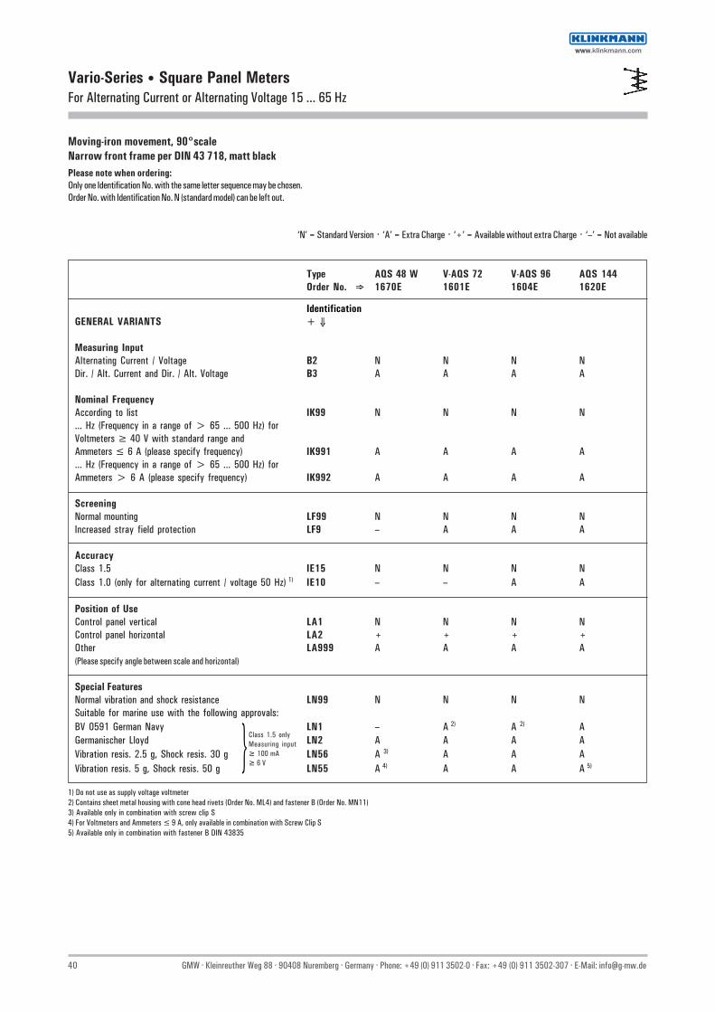
40 GMW · Kleinreuther Weg 88 · 90408 Nuremberg · Germany · Phone: +49 (0) 911 3502-0 · Fax: +49 (0) 911 3502-307 · E-Mail: [email protected]
Vario-Series • Square Panel MetersFor Alternating Current or Alternating Voltage 15 ... 65 Hz
Moving-iron movement, 90°scaleNarrow front frame per DIN 43 718, matt blackPlease note when ordering:Only one Identification No. with the same letter sequence may be chosen.Order No. with Identification No. N (standard model) can be left out.
‘N’ = Standard Version · ‘A’ = Extra Charge · ‘+’ = Available without extra Charge · ‘–’ = Not available
Type AQS 48 W V-AQS 72 V-AQS 96 AQS 144Order No. ⇒ 1670E 1601E 1604E 1620E
IdentificationGENERAL VARIANTS + ⇓
Measuring InputAlternating Current / Voltage B2 N N N NDir. / Alt. Current and Dir. / Alt. Voltage B3 A A A A
Nominal FrequencyAccording to list IK99 N N N N... Hz (Frequency in a range of > 65 ... 500 Hz) forVoltmeters ≥ 40 V with standard range andAmmeters ≤ 6 A (please specify frequency) IK991 A A A A... Hz (Frequency in a range of > 65 ... 500 Hz) forAmmeters > 6 A (please specify frequency) IK992 A A A A
ScreeningNormal mounting LF99 N N N NIncreased stray field protection LF9 – A A A
AccuracyClass 1.5 IE15 N N N NClass 1.0 (only for alternating current / voltage 50 Hz) 1) IE10 – – A A
Position of UseControl panel vertical LA1 N N N NControl panel horizontal LA2 + + + +Other LA999 A A A A(Please specify angle between scale and horizontal)
Special FeaturesNormal vibration and shock resistance LN99 N N N NSuitable for marine use with the following approvals:BV 0591 German Navy LN1 – A 2) A 2) AGermanischer Lloyd LN2 A A A AVibration resis. 2.5 g, Shock resis. 30 g LN56 A 3) A A AVibration resis. 5 g, Shock resis. 50 g LN55 A 4) A A A 5)
Class 1.5 onlyMeasuring input≥ 100 mA≥ 6 V
1) Do not use as supply voltage voltmeter2) Contains sheet metal housing with cone head rivets (Order No. ML4) and fastener B (Order No. MN11)3) Available only in combination with screw clip S4) For Voltmeters and Ammeters ≤ 9 A, only available in combination with Screw Clip S5) Available only in combination with fastener B DIN 43835
wwwwww.klinkmann.com

GMW · Kleinreuther Weg 88 · 90408 Nuremberg · Germany · Phone: +49 (0) 911 3502-0 · Fax: +49 (0) 911 3502-307 · E-Mail: [email protected] 41
Vario-Series • Square Panel MetersFor Alternating Current or Alternating Voltage 15 ... 65 Hz
Moving-iron movement, 90° scaleNarrow front frame per DIN 43 718, matt blackPlease note when ordering:Only one Identification No. with the same letter sequence may be chosen.Order No. with Identification No. N (standard model) can be left out.
‘N’ = Standard Version · ‘A’ = Extra Charge · ‘+’ = Available without extra Charge · ‘–’ = Not available
Type AQS 48 W V-AQS 72 V-AQS 96 AQS 144Order No. ⇒ 1670E 1601E 1604E 1620E
IdentificationSCALE VARIANTS +⇓
ScaleIn accordance with measuring input GF99 N N N NBlank scale (lower and upper value markings.
company logos. symbols) GF24 + + + +
Division and PointerSingle division GD1 N N N NDouble division GD2 – A A ACoarse-fine division SE1 N N N NFine division SE3 – A A ABeam pointer with for single division RA1 N N N Nknife-edge for double divison RA2 + + + +
Additional ImprintSecond numbering (specify in clear text) SK992 A A A AInscription:
Without additional inscription SM99 N N N NInscription ≤ 15 characters German SM991 A A A A
>15 characters German SM992 A A A A≤ 15 characters other language SM993 A A A A>15 characters other language SM994 – A A A
(Other language in Latin lettering. specify in clear text)Coloured mark red RAL 2002
(Specify in clear text) ST991 A A A AColoured sectors yellow RAL 1021, green RAL 6018or red RAL 2002 (Specify in clear text) SU991 A A A A
Scale CharacteristicsInterchangeable scale SA10 N N N –Screw mounted scale SA11 – A A N 1)
OverloadNo overload BU99 N N N N1.2 x of rated value2) BU5 + + + +2 x of rated value (Ammeter only) BU10 + + + +4 x of rated value (Ammeter only) BU12 – A 4) A 4) –6 x of rated value (Ammeter only) BU14 – A A –
1) Standard version without extra charge2) Do not use as supply voltage voltmeter3) Upper value of measuring range ≤ 9 A4) Upper value of measuring range ≤ 40 A
wwwwww.klinkmann.com
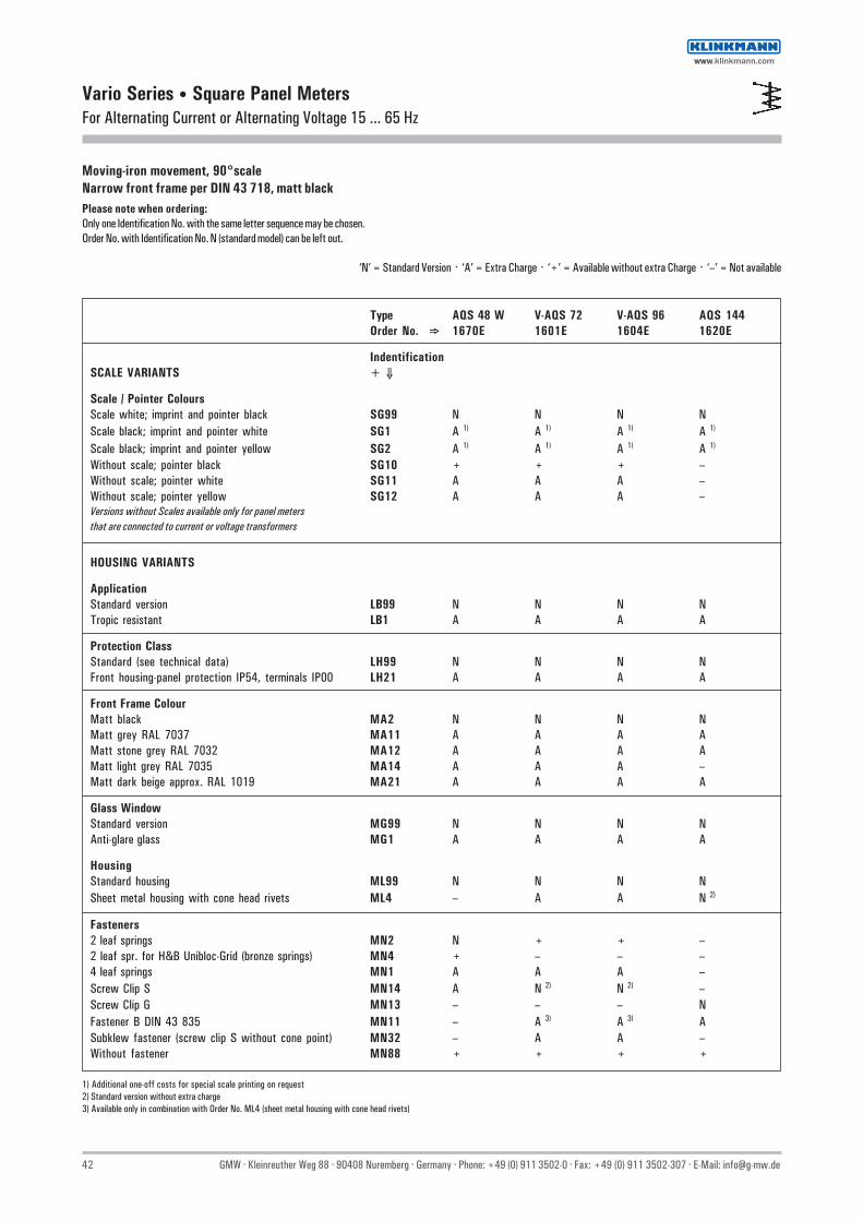
42 GMW · Kleinreuther Weg 88 · 90408 Nuremberg · Germany · Phone: +49 (0) 911 3502-0 · Fax: +49 (0) 911 3502-307 · E-Mail: [email protected]
Vario Series • Square Panel MetersFor Alternating Current or Alternating Voltage 15 ... 65 Hz
Moving-iron movement, 90°scaleNarrow front frame per DIN 43 718, matt blackPlease note when ordering:Only one Identification No. with the same letter sequence may be chosen.Order No. with Identification No. N (standard model) can be left out.
‘N’ = Standard Version · ‘A’ = Extra Charge · ‘+’ = Available without extra Charge · ‘–’ = Not available
Type AQS 48 W V-AQS 72 V-AQS 96 AQS 144Order No. ⇒ 1670E 1601E 1604E 1620E
IndentificationSCALE VARIANTS + ⇓
Scale / Pointer ColoursScale white; imprint and pointer black SG99 N N N NScale black; imprint and pointer white SG1 A 1) A 1) A 1) A 1)
Scale black; imprint and pointer yellow SG2 A 1) A 1) A 1) A 1)
Without scale; pointer black SG10 + + + –Without scale; pointer white SG11 A A A –Without scale; pointer yellow SG12 A A A –Versions without Scales available only for panel metersthat are connected to current or voltage transformers
HOUSING VARIANTS
ApplicationStandard version LB99 N N N NTropic resistant LB1 A A A A
Protection ClassStandard (see technical data) LH99 N N N NFront housing-panel protection IP54, terminals IP00 LH21 A A A A
Front Frame ColourMatt black MA2 N N N NMatt grey RAL 7037 MA11 A A A AMatt stone grey RAL 7032 MA12 A A A AMatt light grey RAL 7035 MA14 A A A –Matt dark beige approx. RAL 1019 MA21 A A A A
Glass WindowStandard version MG99 N N N NAnti-glare glass MG1 A A A A
HousingStandard housing ML99 N N N NSheet metal housing with cone head rivets ML4 – A A N 2)
Fasteners2 leaf springs MN2 N + + –2 leaf spr. for H&B Unibloc-Grid (bronze springs) MN4 + – – –4 leaf springs MN1 A A A –Screw Clip S MN14 A N 2) N 2) –Screw Clip G MN13 – – – NFastener B DIN 43 835 MN11 – A 3) A 3) ASubklew fastener (screw clip S without cone point) MN32 – A A –Without fastener MN88 + + + +
1) Additional one-off costs for special scale printing on request2) Standard version without extra charge3) Available only in combination with Order No. ML4 (sheet metal housing with cone head rivets)
wwwwww.klinkmann.com

GMW · Kleinreuther Weg 88 · 90408 Nuremberg · Germany · Phone: +49 (0) 911 3502-0 · Fax: +49 (0) 911 3502-307 · E-Mail: [email protected] 43
Vario-Series • Square Panel MetersFor Alternating Current or Alternating Voltage 15 ... 65 Hz
Moving-iron movement, 90°scaleNarrow front frame per DIN 43 718, matt blackPlease note when ordering:Only one Identification No. with the same letter sequence may be chosen.Order No. with Identification No. N (standard model) can be left out.
‘N’ = Standard Version · ‘A’ = Extra Charge · ‘+’ = Available without extra Charge · ‘–’ = Not available
Type AQS 48 W V-AQS 72 V-AQS 96 AQS 144Order No. ⇒ 1670E 1601E 1604E 1620E
IdentificationHOUSING VARIANTS + ⇓
IdentificationWithout identification MZ99 N N N NIdentification on the back (specify in clear text) MZ998 A A A A
Marker PointerWithout marker pointer PM99 N N N NAdjustable red index pointer PM1 A A A A
Contact ProtectionWithout terminal cover VB99 N N N NOverall terminal cover VB2 A A A ASingle terminal cover VB1 + + + +
(Voltmeter and Ammeter ≤ 9 A or ≤ 25 Afor size 48 x 48 mm)
wwwwww.klinkmann.com

44 GMW · Kleinreuther Weg 88 · 90408 Nuremberg · Germany · Phone: +49 (0) 911 3502-0 · Fax: +49 (0) 911 3502-307 · E-Mail: [email protected]
Vario-Series • Square Panel MetersFor Alternating Current
Bimetal movement, 90° scaleNarrow front frame per DIN 43 718, matt black
Technical Data
Front Dimensions mm 48 x 48 72 x 72 96 x 96 144 x 144 Type V-MQS 48 V-MQS 72 V-MQS 96 MQS 144
Scale Length mm 34 66 94 143 Class 3 3 3 3 Weight approx. (kg) 0.1 0.2 0.25 0.6 Operating Voltage 300 V 600 V 600 V 600 V Test Voltage 3.5 kV 5.8 kV 5.8 kV 5.8 kV Front Housing-Panel Protection IP 52 IP 52 IP 52 IP 52 Fasteners (see next page) leaf spring screw clip S screw clip S screw clip G Housing Material polycarbonate polycarbonate polycarbonate sheet metal Interchangeable Scale yes yes yes no
V-MQS 96
DescriptionAnalog panel meter with bimetal movement
DisplayScale Division Coarse-finePointer Beam pointer with knife-edge
Mechanical DesignHousing Material Polycarbonate, self-extinguishing and drip-proof per UL 94
V - 0 or sheet metal housing (see above).Sheet metal housings available as option for type V-MQS72 andV-MQS96
Replaceable Glass windows, front frames and scales (interchangeablescales not available for panel meters with front paneldimensions of 144 x 144 mm)⇒ May only be replaced under voltage-free conditions!
Terminals M4 screw terminals with self-lifting terminal clips. Screws can be turned with a cross-head or standard srew drivers
Contact Protection Available as option
Power Consumption
Front Dimensions48 x 48 72 x 72 96 x 96 144 x 144
Con. to Transformer sec. 1 A ap. 1.1 VA ap. 1.1 VA ap. 1.1 VA ap. 1.1 VA sec. 5 A ap. 1.9 VA ap. 1.9 VA ap. 1.9 VA ap. 1.9 VA
Reference Conditions
Reference Quantities Reference Conditions
Ambient Temperature 23 °C ±2°C Position of Use control panel vertical ±1° Other DIN EN 60 051
Overload Capacity
Continous 120 % of rated value Short-term 10 x of rated value; 1 s (Imax =10 A)
wwwwww.klinkmann.com

GMW · Kleinreuther Weg 88 · 90408 Nuremberg · Germany · Phone: +49 (0) 911 3502-0 · Fax: +49 (0) 911 3502-307 · E-Mail: [email protected] 45
Vario-Series • Square Panel MetersFor Alternating Current
Leaf Spring
Control panel thickness 1 to 3 mm.For size 48 x 48 mm, not appropriate for Mauell-Grid.Also available as option for sizes 72 x 72 and 96 x 96 mm.
Screw Clip G
Control panel thickness 1 to 32 mm.Special screw clamp M4 required for size 144 x 144 mm.
Basic Dimensions
Screw Clip S
Control panel thickness 1 to 25 mm.Special screw clamp M4 required for panelmeters with front panel dimensions of 72 x 72 and 96 x 96 mm.Also available as option for size 48 x 48 mm, not appropriate for Mauell-Grid.
Fasteners B DIN 43 835
Control panel thickness 1 to 40 mm.Screw clamp M4 available as option for: Sheet metal housings 72 x 72 and 96 x 96 mm with cone head rivets and size 144 x 144 mm
Dimensions for separate Current Transformer1 A: 67 x 45 x 90 (B x T x H)5 A: 67 x 51 x 90 (B x T x H)
Drawings to Scale (on request)1303 A 2005 H
Ordering ExampleBimetal ammeter 96 x 96 mmConnection to current transformer 25/5 AOverload 1.2 x of rated valueResponse time 15 min.
Techn. Data Order No. V-MQS 96 1604M, BE11, BU5, CG25
Front Nominal Dimensions Cutout Dimensions Installation Depth TerminalsDimensions mm mm M4mm a1 x a2 h l1 x l2 t e
48 x 48 48 x 48 5 45+0.6 x 45+0.6 43.5 12.5 72 x 72 72 x 72 5 68+0.7 x 68+0.7 43.5 12.5 96 x 96 96 x 96 5 92+0.8 x 92+0.8 43.5 12.5 144 x 144 144 x 144 8 138+1 x 138+1 44.5 12.5
1) Single terminal cover2) Overall terminal cover (22 mm for panel meters with front panel dimensions of 48 x 48 mm only)
wwwwww.klinkmann.com

46 GMW · Kleinreuther Weg 88 · 90408 Nuremberg · Germany · Phone: +49 (0) 911 3502-0 · Fax: +49 (0) 911 3502-307 · E-Mail: [email protected]
Vario-Series • Square Panel MetersFor Alternating Current
Bimetal movement, 90° scaleNarrow front frame per DIN 43 718, matt black
Type V-MQS 48 V-MQS 721) V-MQS 961) MQS 144Order No. ⇒ 1662M 1601M 1604M 1620M
Alternating Current + ⇓ Direct Connection
Range:0 ... 1 A CC1, BU5 2) + + + +0 ... 5 A CC5, BU5 2) + + + +
Con. to Current Transformer sec. 1 A BE10, BU5 2) + + + + Con. to Current Transfotmer sec. 5 A BE11, BU5 2) + + + +
Scale:1 A CG1 + + + +5 A CG5 + + + +10 A CG10 + + + +15 A CG15 + + + +20 A CG20 + + + +25 A CG25 + + + +30 A CG30 + + + +40 A CG40 + + + +50 A CG50 + + + +60 A CG60 + + + +75 A CG75 + + + +100 A CG100 + + + +150 A CG150 + + + +200 A CG200 + + + +250 A CG250 + + + +300 A CG300 + + + +400 A CG400 + + + +500 A CG500 + + + +600 A CG600 + + + +750 A CG750 + + + +800 A CG800 + + + +
0 ... >1 A < 1 kA 3) CG... + + + +
1 kA CH1 + + + +5 kA CH5 + + + +10 kA CH10 + + + +
0 ... > 1 kA 3) CH... + + + +
Note:Choose only one of the listed measuring inputs. ‘A’ = Extra Charge · ‘+’ = Available without extra Charge · ‘–’ = Not available
1) For sheet metal housings with cone head rivets please see “Housing Variants“2) Upper scale value = 120% of rated value3) Specify in clear text
wwwwww.klinkmann.com

GMW · Kleinreuther Weg 88 · 90408 Nuremberg · Germany · Phone: +49 (0) 911 3502-0 · Fax: +49 (0) 911 3502-307 · E-Mail: [email protected] 47
Vario-Series • Square Panel Meters
Bimetal movement, 90° scaleNarrow front frame per DIN 43 718, matt black
Please note when ordering:Only one Identification No. with the same letter sequence may be chosen.Order No. with Identification No. N (standard model) can be left out.
‘N’ = Standard Version · ‘A’ = Extra Charge · ‘+’ = Available without extra Charge · ‘–’ = Not available
Type V-MQS 48 V-MQS 72 V-MQS 96 MQS 144Order No. ⇒ 1662M 1601M 1604M 1620M
IdentificationGENERAL VARIANTS + ⇓
Response TimeResponse time 15 min. IB1 N N N NResponse time 8 min. IB2 + + + +
OverloadOverload 1.2 x of rated value BU5 N N N NOverload 1.2 x of rated value with built in
prot. cur. transf. 100 x of rated value / 1s BU26 – – – AOverload 1.2 x of rated value with separated
prot. cur. transf 100 x of rated value / 1s BU27 A A A –
Position of UseControl panel vertical LA1 N N N NControl panel horizontal LA2 + + + +
Other LA999 A A A A(Please specify angle between scale and horizontal)
SCALE VARIANTS
ScaleIn accordance with measuring input GF99 N N N NBlank scale (lower and upper value markings, GF24 + + + +
company logos, symbols)
Additional ImprintSecond numbering (specify in clear text) SK992 A A A AInscription:Without additional inscription SM99 N N N NInscription≤ 15 characters German SM991 A A A A
>15 characters German SM992 A A A A≤ 15 characters other language SM993 A A A A>15 characters other language SM994 A A A A
(Other language in Latin lettering, specify in clear text)Coloured mark red RAL 2002 (specify in clear text) ST991 A A A AColoured sector yellow RAL 1021, green RAL 6018
or red RAL 2002 (specify in clear text) SU991 A A A A
Scale / Pointer ColoursScale white; imprint und pointer black SG99 N N N NScale black; imprint und pointer white SG1 A 1) A 1) A 1) A 1)
Scale black; imprint und pointer yellow SG2 A 1) A 1) A 1) A 1)
Without scale; pointer black SG10 + + + –Without scale; pointer white SG11 A A A –Without scale; pointer yellow SG12 A A A –
1) Additional one-off costs for special scale printing on request
For Alternating Current
wwwwww.klinkmann.com

48 GMW · Kleinreuther Weg 88 · 90408 Nuremberg · Germany · Phone: +49 (0) 911 3502-0 · Fax: +49 (0) 911 3502-307 · E-Mail: [email protected]
Vario-Series • Square Panel MetersFor Alternating Current
Bimetal movement, 90° scaleNarrow front frame per DIN 43 718, matt black
Please note when ordering:Only one Identification No. with the same letter sequence may be chosen.Order No. with Identification No. N (standard model) can be left out.
‘N’ = Standard Version · ‘A’ = Extra Charge · ‘+’ = Available without extra Charge · ‘–’ = Not available
Type V-MQS 48 V-MQS 72 V-MQS 96 MQS 144Order No. ⇒ 1662M 1601M 1604M 1620M
IdentificationHOUSING VARIANTS + ⇓
Front Frame ColoursMatt black MA2 N N N NMatt grey RAL 7037 MA11 A A A AMatt stone grey RAL 7032 MA12 A A A AMatt dark beige approx. RAL 1019 MA21 A A A A
Glass WindowsStandard version MG99 N N N NAnti-glare glass MG1 A A A A
HousingStandard housing ML99 N N N NSheet metal housing with cone head rivets ML4 – A A N 1)
Mounting2 Leaf springs MN2 N + + –4 Leaf springs MN1 A A A –Screw Clip S MN14 A N 1) N 1) –Screw Clip G MN13 – – – NFastener B DIN 43 835 MN11 – A 2) A 2) A
IdentificationWithout Identification MZ99 N N N NIdentification on the back (Specify in clear text) MZ998 A A A A
Contact ProtectionWithout terminal cover VB99 N N N NOverall terminal cover VB2 A A A ASingle terminal cover VB1 + + + +
1) Standard version without extra charge2) Available only in combination with Order No. MLX 4 (sheet metal housing with cone head rivets)
wwwwww.klinkmann.com
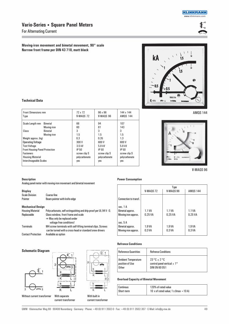
GMW · Kleinreuther Weg 88 · 90408 Nuremberg · Germany · Phone: +49 (0) 911 3502-0 · Fax: +49 (0) 911 3502-307 · E-Mail: [email protected] 49
Vario-Series • Square Panel MetersFor Alternating Current
Technical Data
Front Dimensions mm 72 x 72 96 x 96 144 x 144 Type V-MAQS 72 V-MAQS 96 AMQS 144
Scale Length mm Bimetal 66 94 107Moving-iron 60 81 143
Class Bimetal 3 3 3Moving-iron 1.5 1.5 1.5
Weight approx. (kg) 0.3 0.35 1.3 Operating Voltage 300 V 600 V 600 V Test Voltage 3.5 kV 5.8 kV 5.8 kV Front Housing-Panel Protection IP 50 IP 50 IP 50 Fasteners screw clip S screw clip S screw clip S Housing Material polycarbonate polycarbonate polycarbonate Interchnageable Scales yes yes yes
Moving-iron movement and bimetal movement, 90° scaleNarrow front frame per DIN 43 718, matt black
V-MAQS 96
DescriptionAnalog panel meter with moving-iron movemant and bimetal movement
DisplayScale Division Coarse-finePointer Beam pointer with knife-edge
Mechanical DesignHousing Material Polycarbonate, self-extinguishing and drip-proof per UL 94 V - 0.Replaceable Glass window, front frame and scale
⇒ May only be replaced under voltage-free conditions!
Terminals M4 screw terminals with self-lifting terminal clips. Screws can be turned with a cross-head or standard srew drivers
Contact Protection Available as option
Refrence Conditions
Reference Quantities Refrence Conditions
Ambient Temperature 23 °C ± 2 °C position of Use control panel vertical ± 1° Other DIN EN 60 051
Overload Capacity of Bimetal Movement
Continous 120% of rated value Short-term 10 x of rated value; 1 s (Imax =10 A)
Power Consumption
TypeV-MAQS 72 V-MAQS 96 AMQS 144
Connection to transf.
sec. 1 A Bimetal approx. 1.1 VA 1.1 VA 1.1 VA Moving-iron approx. 0.25 VA 0.25 VA 0.25 VA
sec. 5 A Bimetal approx. 1.9 VA 1.9 VA 1.9 VA Moving-iron approx. 0.3 VA 0.3 VA 0.3 VA
Schematic Diagram
Without current transformer With separate With built incurrent transformer current transformer
AMQS 144
wwwwww.klinkmann.com

50 GMW · Kleinreuther Weg 88 · 90408 Nuremberg · Germany · Phone: +49 (0) 911 3502-0 · Fax: +49 (0) 911 3502-307 · E-Mail: [email protected]
Vario-Series • Square Panel MetersFor Alternating Current
Leaf Spring
Control panel thickness 1 to 3 mm.Also available as option for sizes of 72 x 72 and 96 x 96 mm.
Screw Clip S
Control panel thickness 1 to 25 mm.Special screw clamp M4 for sizes 72 x 72 and 96 x 96 mm.
Fastener B DIN 43 835
Control panel thickness 1 to 40 mm.Screw clamp M4 as option for sizes 72 x 72 and 96 x 96 mm.
Dimensions for Current Transformers1 A: 67 x 45 x 90 (B x T x H)5 A: 67 x 51 x 90 (B x T x H)
Drawings to Scale (on request)1303 A 2005 H
Ordering ExamplePanel meter 96 x 96 mm, with bimetal and moving-iron movementConnection to current transformer 25/5 AOverload 1.2 x of rated value for bimetal movement, 2 x of rated value for moving-ironmovementResponse time 15 min.
Techn. Data Order No. 1606C V-MAQS 96 Movement I (Bimetal) 1BE11, 1BU5, 1CG25
Movement II (Moving-iron) 2BE11, 2BW10, 2CG25
Front in mm Nominal Dimensions Cutout Dimensions, mm Installation Depth TerminalsM4
a1 x a2 h l1 x l2 t e
72 x 72 72 x 72 5 68+0.7 x 68+0.7 43.5 12.5 96 x 96 96 x 96 5 92+0.8 x 92+0.8 43.5 12.5 144 x 144 144 x 144 8 138+1 x 138+1 95.0 12.5
Drawings to scale (on request)0101A259
Basic Dimensions
1) Single terminal cover2) Overall terminal cover
wwwwww.klinkmann.com
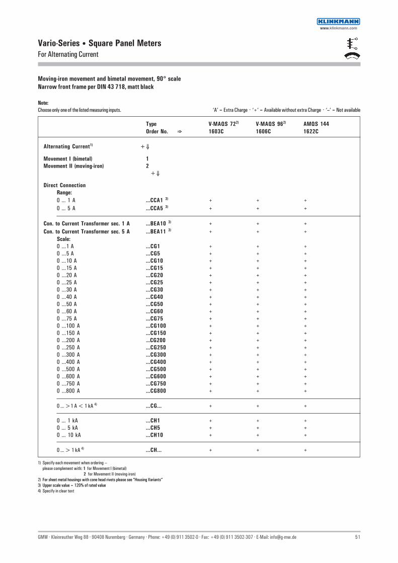
GMW · Kleinreuther Weg 88 · 90408 Nuremberg · Germany · Phone: +49 (0) 911 3502-0 · Fax: +49 (0) 911 3502-307 · E-Mail: [email protected] 51
Vario-Series • Square Panel MetersFor Alternating Current
Moving-iron movement and bimetal movement, 90° scaleNarrow front frame per DIN 43 718, matt black
Note:Choose only one of the listed measuring inputs. ‘A’ = Extra Charge · ‘+’ = Available without extra Charge · ‘–’ = Not available
Type V-MAQS 722) V-MAQS 962) AMQS 144Order No. ⇒ 1603C 1606C 1622C
Alternating Current1) +⇓
Movement I (bimetal) 1Movement II (moving-iron) 2
+⇓
Direct ConnectionRange:0 ... 1 A ...CCA1 3) + + +0 ... 5 A ...CCA5 3) + + +
Con. to Current Transformer sec. 1 A ...BEA10 3) + + +Con. to Current Transformer sec. 5 A ...BEA11 3) + + +
Scale:0 ...1 A ...CG1 + + +0 ...5 A ...CG5 + + +0 ...10 A ...CG10 + + +0 ...15 A ...CG15 + + +0 ...20 A ...CG20 + + +0 ...25 A ...CG25 + + +0 ...30 A ...CG30 + + +0 ...40 A ...CG40 + + +0 ...50 A ...CG50 + + +0 ...60 A ...CG60 + + +0 ...75 A ...CG75 + + +0 ...100 A ...CG100 + + +0 ...150 A ...CG150 + + +0 ...200 A ...CG200 + + +0 ...250 A ...CG250 + + +0 ...300 A ...CG300 + + +0 ...400 A ...CG400 + + +0 ...500 A ...CG500 + + +0 ...600 A ...CG600 + + +0 ...750 A ...CG750 + + +0 ...800 A ...CG800 + + +
0 ... >1 A < 1 kA 4) ...CG... + + +
0 ... 1 kA ...CH1 + + +0 ... 5 kA ...CH5 + + +0 ... 10 kA ...CH10 + + +
0 ... > 1 kA 4) ...CH... + + +
1) Specify each movement when ordering –please complement with: 1 for Movement I (bimetal)
2 for Movement II (moving-iron)2) For sheet metal housings with cone head rivets please see “Housing Variants“3) Upper scale value = 120% of rated value4) Specify in clear text
wwwwww.klinkmann.com
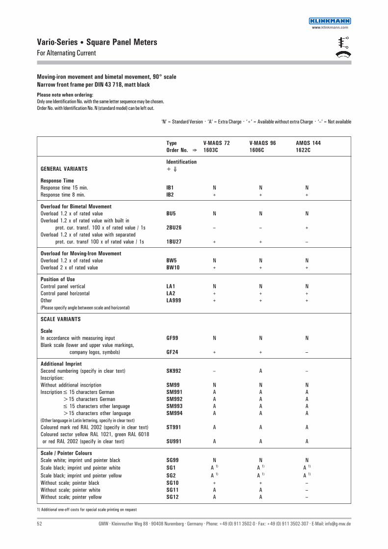
52 GMW · Kleinreuther Weg 88 · 90408 Nuremberg · Germany · Phone: +49 (0) 911 3502-0 · Fax: +49 (0) 911 3502-307 · E-Mail: [email protected]
Vario-Series • Square Panel MetersFor Alternating Current
Moving-iron movement and bimetal movement, 90° scaleNarrow front frame per DIN 43 718, matt black
Please note when ordering:Only one Identification No. with the same letter sequence may be chosen.Order No. with Identification No. N (standard model) can be left out.
‘N’ = Standard Version · ‘A’ = Extra Charge · ‘+’ = Available without extra Charge · ‘–’ = Not available
Type V-MAQS 72 V-MAQS 96 AMQS 144Order No. ⇒ 1603C 1606C 1622C
IdentificationGENERAL VARIANTS + ⇓
Response TimeResponse time 15 min. IB1 N N NResponse time 8 min. IB2 + + +
Overload for Bimetal MovementOverload 1.2 x of rated value BU5 N N NOverload 1.2 x of rated value with built in
prot. cur. transf. 100 x of rated value / 1s 2BU26 – – +Overload 1.2 x of rated value with separated
prot. cur. transf 100 x of rated value / 1s 1BU27 + + –
Overload for Moving-Iron MovementOverload 1.2 x of rated value BW5 N N NOverload 2 x of rated value BW10 + + +
Position of UseControl panel vertical LA1 N N NControl panel horizontal LA2 + + +Other LA999 + + +(Please specify angle between scale and horizontal)
SCALE VARIANTS
ScaleIn accordance with measuring input GF99 N N NBlank scale (lower and upper value markings,
company logos, symbols) GF24 + + –
Additional ImprintSecond numbering (specify in clear text) SK992 – A –Inscription:Without additional inscription SM99 N N NInscription≤ 15 characters German SM991 A A A
>15 characters German SM992 A A A≤ 15 characters other language SM993 A A A>15 characters other language SM994 A A A
(Other language in Latin lettering, specify in clear text)Coloured mark red RAL 2002 (specify in clear text) ST991 A A AColoured sector yellow RAL 1021, green RAL 6018 or red RAL 2002 (specify in clear text) SU991 A A A
Scale / Pointer ColoursScale white; imprint und pointer black SG99 N N NScale black; imprint und pointer white SG1 A 1) A 1) A 1)
Scale black; imprint und pointer yellow SG2 A 1) A 1) A 1)
Without scale; pointer black SG10 + + –Without scale; pointer white SG11 A A –Without scale; pointer yellow SG12 A A –
1) Additional one-off costs for special scale printing on request
wwwwww.klinkmann.com

GMW · Kleinreuther Weg 88 · 90408 Nuremberg · Germany · Phone: +49 (0) 911 3502-0 · Fax: +49 (0) 911 3502-307 · E-Mail: [email protected] 53
Vario-Series • Square Panel MetersFor Alternating Current
Moving-iron movement and bimetal movement, 90° scaleNarrow front frame per DIN 43 718, matt black
Please note when ordering:Only one Identification No. with the same letter sequence may be chosen.Order No. with Identification No. N (standard model) can be left out.
‘N’ = Standard Version · ‘A’ = Extra Charge · ‘+’ = Available without extra Charge · ‘–’ = Not available
Type V-MAQS 72 V-MAQS 96 AMQS 144Order No. ⇒ 1603C 1606C 1622C
IdentificationHOUSING VARIANTS + ⇓
Front Frame ColoursMatt black MA2 N N NMatt grey RAL 7037 MA11 A A AMatt stone grey RAL 7032 MA12 A A AMatt light grey RAL 7035 MA14 A A —Matt dark beige approx. RAL 1019 MA21 A A A
Intermediate Frame. Height 3 mmWithout intermediate frame MC99 N N NIntermediate frame shiny black MC1 A A AIntermediate frame shiny grey RAL 7037 MC2 A A AIntermediate frame available only in combination withscrew clip S or fastener B DIN 43 835
Glass WindowStandard version MG99 N N NAnti-glare glass MG1 A A A
HousingStandard housing ML99 N N NSheet metal housing with cone head rivets ML4 A A N 1)
Mounting2 Leaf springs MN2 + + –4 Leaf springs MN1 A A –Screw Clip S MN14 N N –Fastener B DIN 43835 MN11 A 2) A 2) N 1)
IdentificationWithout identification MZ99 N N NIdentification on the back (specify in clear text) MZ998 A A A
Constant DisplayWithout constant display PK99 N N NConstant display 1-1.5-2-2.5-3-4-5-6-7.5-8-10 PK5 – A A
Contact ProtectionWithout terminal cover VB99 N N NOverall terminal cover VB2 A A ASingle terminal cover VB1 + + +
1) Standard version without extra charge2) Available only in combination with Order No. ML4 (sheet metal housing with cone head rivets)
wwwwww.klinkmann.com

54 GMW · Kleinreuther Weg 88 · 90408 Nuremberg · Germany · Phone: +49 (0) 911 3502-0 · Fax: +49 (0) 911 3502-307 · E-Mail: [email protected]
Vario-Series • Square Panel MetersFor Alternating Current or Alternating Voltage 40 ... 50 ... 10 000 Hz
Moving-coil movement with rectifier, 90° or 240° scaleNarrow front frame per DIN 43 718, matt black
V-PQS 96Technical Data
Front Dimensions mm 48 x 48 72 x 72 96 x 96 144 x 144
Type (90° Scale) PQS 48 W V-PQS 72 V-PQS 96 PQS 144 Scale Length mm 40 66 94 143
Type (240° Scale) V-PQ 48-250 V-PQ 72-250 V-PQ 96-250 PQ 144-250 Scale Length mm 73 113 151 235
Class 1.5 1.5 1.5 1.5 Weight approx. (90° / 240°) (kg) 0.08 / 0.16 0.2 / 0.2 0.25 / 0.25 0.6 / 0.65 Operating Voltage 300 V 600 V 600 V 600 V Test Voltage 3.5 kV 5.8 kV 5.8 kV 5.8 kV Front Housing-Panel Protection IP 52 IP 52 IP 52 IP 52 Fasteners (see next page) leaf spring screw clip S screw clip S screw clip G Housing Material polycarbonate polycarbonate polycarbonate sheet metal Interchangeable Scale yes yes yes no
DescriptionAnalog panel meter with moving-coil movement and rectifier
DisplayScale Division Coarse-finePointer Beam Pointer with knife-edge
Mechanical DesignHousing Material Polycarbonate, self-extinguishing and drip-proof per UL 94 V - 0
or sheet metal housing (see above).Sheet metal housing available as option for type V-PQS 72,V-PQS 96, V-PQ 72-250 and V-PQ 96-250 .
Replaceable Glass windows, front frames and scales (interchangeablescales not available for panel meters with front paneldimensions of 144 x 144 mm)⇒ May only be replaced under voltage-free conditions!
Terminals M4 screw terminals with self-lifting terminal clips. Screws can be turned with a cross-head or standard screw drivers
Contact Protection Available as option
Voltage Drop / Power ConsumptionVoltage drop withmeasuring range <100 mA: approx. 1.2 VPower consumption withmeasuring range ≥100 mA: approx. 0.15 VA
Reference Conditions
Reference Quantities Reference Conditions
Wave Shape sine, distortion factor ≤1% Frequency 50 Hz ±2 % Ambient Temperature 23 °C ±2 °C Position of Use control panel vertical ± 1° Other DIN EN 60 051
V-PQ 96-250
wwwwww.klinkmann.com

GMW · Kleinreuther Weg 88 · 90408 Nuremberg · Germany · Phone: +49 (0) 911 3502-0 · Fax: +49 (0) 911 3502-307 · E-Mail: [email protected] 55
Leaf Spring
Control panel thickness 1 to 3 mm.For size 48 x 48 mm, not available for Mauell-Grid.Also available as option for sizes 72 x 72 and 96 x 96 mm.
Screw Clip G
Control panel thickness 1 to 32 mm.Special screw clamp M4 required for size144 x 144 mm.
Basic Dimensions
Drawings to Scale (on request)0101A258 for size 48 x 48 mm0101A259 for sizes 72 x 72 and 96 x 96 mm0101A261 sheet 1 for size 144 x 144 mm
Screw Clip S
Control panel thickness 1 to 25 mm.Special screw clamp M4 required for size72 x 72 and 96 x 96 mm.Also available as option for size 48 x 48 mm, not available for Mauell-Grid.
Fastener B DIN 43 835
Control panel thickness 1 to 40 mm.Screw clamp M4 as option for: Sheet metal housings 72 x 72 and 96 x 96 mm with cone head rivets and size 144 x 144 mm.
Dimensions for separated Saturation Current Transformer80 x 55 x 31 mm (L x B x H)
Drawing to Scale (on request)1303A1839H0
Ordering ExamplePanel meter 96 x 96 mmScale 240°0 ... 40 V Alternating voltage
Type Order No. V-PQ 96-250 1605W, DC40
Vario-Series • Square Panel MetersFor Alternating Current or Alternating Voltage 40 ... 50 ... 10 000 Hz
Front Dimensions Nominal Dimensions Cutout Dimensions Installation Depth Terminals mm
≥ 100 mA
M4 M3a1 x a2 h l1 x l2 t t1 e e
48 x 48 48 x 48 5 45+0.6 x 45+0.6 43.5 61.5 3) 12.5 5.5 72 x 72 72 x 72 5 68+0.7 x 68+0.7 43.5 – 12.5 – 96 x 96 96 x 96 5 92+0.8 x 92+0.8 43.5 – 12.5 – 144 x 144 144 x 144 8 138+1 x 138+1 44.5 – 12.5 –
1) Single terminal cover2) Overall terminal cover (22 mm for panel meters with front panel dimensions of 48 x 48 mm only)3) ≥100 mA with attached intermediate transformer (available only for V-PQ 48-250)
wwwwww.klinkmann.com

56 GMW · Kleinreuther Weg 88 · 90408 Nuremberg · Germany · Phone: +49 (0) 911 3502-0 · Fax: +49 (0) 911 3502-307 · E-Mail: [email protected]
Vario-Series • Square Panel MetersFor Alternating Current or Alternating Voltage 40 ... 50 ... 10 000 Hz
Moving-coil movement with rectifier, 90° or 240° scaleNarrow front frame per DIN 43 718, matt black
Type (90° Scale) PQS 48 W V-PQS 72 V-PQS 96 PQS 144Order No. ⇒ 1670W 1601W 1604W 1620W
Type (240° Scale) V-PQ 48-250 V-PQ 72-250 V-PQ 96-250 PQ 144-250Order No. ⇒ 1668W 1602W 1605W 1621W
Alterating Current 1) +⇓Range:0 ... 100 µA 2) CA100 A A A A0 ... 150 µA CA150 A A A A0 ... 250 µA CA250 A A A A0 ... 400 µA CA400 A A A A0 ... 600 µA CA600 A A A A0 ... >100 µA ... <1 mA 3) CA... A A A A
0 ... 1 mA CB1 + + + +0 ... 1.5 mA CB1.5 + + + +0 ... 2.5 mA CB2.5 + + + +0 ... 4 mA CB4 + + + +0 ... 6 mA CB6 + + + +0 ... 10 mA CB10 + + + +0 ... 15 mA CB15 A A A A0 ... 25 mA CB25 A A A A0 ... 40 mA CB40 A A A A0 ... 60 mA CB60 A A A A0 ... 100 mA CB100 A A A A0 ... 150 mA CB150 A A A A0 ... 250 mA CB250 A A A A0 ... 400 mA CB400 A A A A0 ... 600 mA CB600 A A A A0 ... >1 mA ... <1 A 3) CB... A A A A0 ... 1 A CC1 A A A A0 ... 1.5 A CC1.5 A A A A0 ... 2.5 A CC2.5 A A A A0 ... 4 A CC4 A A A A0 ... >1 A ... <5 A 3) CC... A A A A
Connection to Current Transformer 1)
...A/1A BE10 A A A A
...A/5A BE11 A A A A
...A/1A BE22 A A A A
...A/5A BE23 A A A A
Scale: ⇓. . . . . . ⇒ 1 A CG1 + + + +5 A CG5 + + + +10 A CG10 + + + +15 A CG15 + + + +25 A CG25 + + + +40 A CG40 + + + +60 A CG60 + + + +100 A CG100 + + + +150 A CG150 + + + +250 A CG250 + + + +400 A CG400 + + + +600 A CG600 + + + +0 ...>1 A ...<1 kA 3) CG... + + + +
1 kA CH1 + + + +1.2 kA CH1.2 + + + +1.5 kA CH1.5 + + + +>1 kA 3) CH... + + + +
‘A’ = Extra Charge · ‘+’ = Available without extra Charge · ‘–’ = Not available
1) ForType PQS 48 W ≥100 mA with separate intermediate transformer2) Not possible with 240° scales3) Specify in clear text
Overload1.2 x of rat. value
complementwith CG...
or CH...
wwwwww.klinkmann.com

GMW · Kleinreuther Weg 88 · 90408 Nuremberg · Germany · Phone: +49 (0) 911 3502-0 · Fax: +49 (0) 911 3502-307 · E-Mail: [email protected] 57
Vario-Series • Square Panel MetersFor Alternating Current or Alternating Voltage 40 ... 50 ... 10 000 Hz
Moving-coil movement with rectifier, 90° or 240° scaleNarrow front frame per DIN 43 718, matt black ‘A’ = Extra Charge · ‘+’ = Available without extra Charge · ‘–’ = Not available
Type (90° Scale) PQS 48 W V-PQS 72 V-PQS 96 PQS 144Order No. ⇒ 1670W 1601W 1604W 1620W
Type (240° Scale) V-PQ 48-250 V-PQ 72-250 V-PQ 96-250 PQ 144-250Order No. ⇒ 1668W 1602W 1605W 1621W
Alternating Voltage +⇓ Zero Point at left
Range:0 ... 2.5 V DC2.5 A A A A0 ... 4 V DC4 A A A A0 ... 6 V DC6 A A A A0 ... 10 V DC10 A A A A0 ... 15 V DC15 A A A A0 ... 25 V DC25 A A A A0 ... 40 V DC40 A A A A0 ... 60 V DC60 A A A A0 ... 100 V DC100 A A A A0 ... 150 V DC150 A A A A0 ... 250 V DC250 A A A A0 ... 400 V DC400 — A A A0 ... 500 V DC500 — A A A0 ... 600 V DC600 — A A A0 ... 800 V DC800 — A A A0 ... 1000 V DC1000 — A A A0 ... >2.5 V <1000 V 1) DC... A 2) A A A
Alternating Voltage Connection to Voltage Transformer
.../100 V sec. BF12 A A A A
.../110 V sec. BF15 A A A A
.../100 V BF25 A A A A
.../110 V BF26 A A A A
.../250 V BF18 A A A A
Scale:0 ... 500 V DG500 + + + +0 ... 600 V DG600 + + + +0 ... >500 V <1 kV 1) DG... + + + +
0 ... 1 kV DH1 + + + +0 ... 3 kV DH3 + + + +0 ... 5 kV DH5 + + + +0 ... 6 kV DH6 + + + +0 ... 10 kV DH10 + + + +0 ... 15 kV DH15 + + + +0 ... 20 kV DH20 + + + +0 ... 25 kV DH25 + + + +0 ... 30 kV DH30 + + + +0 ... >1 kV 1) DH... + + + +
1) Specify in clear text2) 0 ... >2.5 V <300 V
Overload1.2 x of rated value
complementwith DG...
or DH...
wwwwww.klinkmann.com

58 GMW · Kleinreuther Weg 88 · 90408 Nuremberg · Germany · Phone: +49 (0) 911 3502-0 · Fax: +49 (0) 911 3502-307 · E-Mail: [email protected]
Vario-Series • Square Panel MetersFor Alternating Current or Alternating Voltage 40 ... 50 ... 10 000 Hz
Moving-coil movement with rectifier, 90° or 240° scaleNarrow front frame per DIN 43 718, matt blackPlease note when ordering:Only one Identification No. with the same letter sequence may be chosen.Order No. with Identification No. N (standard model) can be left out.
‘N’ = Standard Version · ‘A’ = Extra Charge · ‘+’ = Available without extra Charge · ‘–’ = Not available
Type (90° Scale) PQS 48 W V-PQS 72 V-PQS 96 PQS 144Order No. ⇒ 1670W 1601W 1604W 1620W
Type (240° Scale) V-PQ 48-250 V-PQ 72-250 V-PQ 96-250 PQ 144-250Order No. ⇒ 1668W 1602W 1605W 1621W
Identification MOVEMENT VARIANTS +⇓
Nominal Frequency Standard (50 Hz) IK2 N N N N Nominal Frequency 60 Hz IK3 A A A A Calibration for Direct Current (Prot. against reverse pol.) IK70 A A A A Nominal Frequency ... Hz 1) (Frequency within a range of IK998 A A A A
≥ 40 Hz / <1 kHz) Nominal Frequency ... kHz 1) (Frequency within a range of IK999 A A A A
≥ 1 kHz / ≤10 kHz)
Internal Resistance with Voltmeters Standard (see technical data) IR99 N N N N Ri approx. 10 kΩ / V (Measuring input ≥ 6 V) IR10 A A A A Ri = 1 kΩ / V ±1% at nom. temperature IR30 A A A A
(Measuring input ≥ 6 V) Ri = 10 kΩ / V ±1% at nom. temperature IR40 A A A A
(Measuring input ≥ 6 V)
Potentiometer for Adjustment with Voltmeters Voltmeters without potentiometer for adjustment MP99 N N N N Voltmeters with potentiometer for adjustment MP1 — A A A Adjustment range ±15 % (Measuring input ≥ 6 V / ≤ 550 V;
Ri according to list)
Position of Use Control panel vertical LA1 N N N N Control panel horizontal LA2 + + + + Other LA999 + + + + (Please specify angle between scale and horizontal)
Special Features Normal vibration and shock resistance LN99 N N N N Suitable for marine use with the following approvals: BV 0591 German Navy LN1 — + 2) + 2) + Germanischer Lloyd LN2 + + + + Vibration resis. 2.5 g, Shock resis. 30 g LN56 + 3) + + + Vibration resis. 5 g, Shock resis. 50 g LN55 + 3) + + + 4)
1) Specify in clear text2) Contains sheet metal housing with cone head rivets (Ident. ML4) and fastener B (Ident. MN11)3) Available only in combination with screw clip S4) Availabel only in combination with fastener B DIN 43835
Class 1.5 onlyMeasuring input≥ 100 mA≥ 6 V
wwwwww.klinkmann.com

GMW · Kleinreuther Weg 88 · 90408 Nuremberg · Germany · Phone: +49 (0) 911 3502-0 · Fax: +49 (0) 911 3502-307 · E-Mail: [email protected] 59
Vario-Series • Square Panel MetersFor Alternating Current or Alternating Voltage 40 ... 50 ... 10 000 Hz
Moving-coil movement with rectifier, 90° or 240° scaleNarrow front frame per DIN 43 718, matt black
Type (90° Scale) PQS 48 W V-PQS 72 V-PQS 96 PQS 144Order No. ⇒ 1670W 1601W 1604W 1620W
Type (240° Scale) V-PQ 48-250 V-PQ 72-250 V-PQ 96-250 PQ 144-250Order No. ⇒ 1668W 1602W 1605W 1621W
Identification SCALE VARIANTS +⇓
ScaleIn accordance with measuring input GF99 N N N NBlank scale (lower & upper marks, co. logo & symbols) GF24 + + + +Scale CharacteristicsCurrent / Voltage linear SD1 N N N NAccording to curve (not current / voltage linear) SD6 A A A A
OverloadNo Overload BU99 N N N N2 x of rated value with built in sat. cur. transformer BU20 – A 1) 6) A 1) A2 x of rated value with separated sat. cur. transformer BU21 A A 2) A 2) 6) –5 x of rated value with built in sat. cur. transformer BU34 – A 1) 6) A 1) A5 x of rated value with separated sat. cur. transformer BU35 A A 2) A 2) 6) –10 x of rated value with built in sat. cur. transformer BU44 – A 3) 6) A 3) A 4)
10 x of rated value with separated sat. cur. transformer BU45 A 4) A 4) A 4) 6) –Saturation current transformer available only for connection to current transformer (Order No. BE10and BE11) and only for a nominal frequency of 50 Hz or 60 Hz
Division and PointerSingle division GD1 N N N NDouble division GD2 A A A ACoarse fine division SE1 N N N NFine division SE3 – A A ABeam pointer with for single division RA1 N N N Nknife-edge for double division RA2 + + + +Knife-edge pointer for single division RA10 A A A A
for double division RA11 A 6) A A ABar indicator 5) for single division RA40 A A A A
Additional ImprintSecond numbering (specify in clear text) SK992 A A A AInscription:
Without additional inscription SM99 N N N NInscription ≤ 15 characters German SM991 A A A A
>15 characters German SM992 A A A A≤ 15 characters other language SM993 A A A A>15 characters other language SM994 A A A A
(Other language in Latin lettering, specify in clear text)Coloured mark red RAL 2002 (specify in clear text) ST991 A A A AColoured sectors yellow RAL 1021, green RAL 6018or red RAL 2002 (specify in clear text) SU991 A A A A
Scale CharacteristicsInterchangeable scale SA10 N N N –Screw mounted scale SA11 A A A NAnti-parallax scale (with bar indicator and single division) 5) SA5 A A A A
1) Not available with dial illumination 4) Only for connection to transformer sec. 1 A2) Available only with dial illumination 5) Only with 240° Scale3) Only for connection to transformer sec. 1 A; Not available with dial illumination 6) Not available with 240° Scale
Please note when ordering:Only one Identification No. with the same letter sequence may be chosen.Order No. with Identification No. N (standard model) can be left out.
‘N’ = Standard Version · ‘A’ = Extra Charge · ‘+’ = Available without extra Charge · ‘–’ = Not available
wwwwww.klinkmann.com

60 GMW · Kleinreuther Weg 88 · 90408 Nuremberg · Germany · Phone: +49 (0) 911 3502-0 · Fax: +49 (0) 911 3502-307 · E-Mail: [email protected]
Vario-Series • Square Oanel MetersFor Alternating Current or Alternating Voltage 40 ... 50 ... 10 000 Hz
Moving-coil movement with rectifier, 90° or 240° scaleNarrow front frame per DIN 43 718, matt blackPlease note when ordering:Only one Identification No. with the same letter sequence may be chosen.Order No. with Identification No. N (standard model) can be left out.
‘N’ = Standard Version · ‘A’ = Extra Charge · ‘+’ = Available without extra Charge · ‘–’ = Not available
Type (90° Scale) PQS 48 W V-PQS 72 V-PQS 96 PQS 144Order No. ⇒ 1670W 1601W 1604W 1620W
Type (240° Scale) V-PQ 48-250 V-PQ 72-250 V-PQ 96-250 PQ 144-250Order No. ⇒ 1668W 1602W 1605W 1621W
IdentificationSCALE VARIANTS +⇓Scale / Pointer ColoursScale white; imprint and pointer black SG99 N N N NScale black; imprint and pointer white SG1 A 1) A 1) A 1) A 1)
Scale black; imprint and pointer yellow SG2 A 1) A 1) A 1) A 1)
Scale black; imprint white, pointer yellow SG3 A 1) A 1) A 1) A 1)
Dial IlluminationWithout dial illumination PA99 N N N NWith direct dial illumination PA1 – A A A(Plexiglass scale, scale and dial illumination white)
Note: Completion with Voltage Order No. PB... necessary.(Dial illumination not available for mirror interchangeablescales and mirror screw mounted scales)
With indirect dial illuminationLight conductor with mask. dial illumination white PA6 – A A ALight conductor with mask. dial illumination red PA7 – A A A
Note: Completion with Voltage Order No. PB... necessary.(SG 99 as light conductor with mask not available)Dial illumination available only with screw mounted scale (Order No. SA11).
Voltage for Dial Illumination 12 V PB3 – + + +
24 V PB5 – + + +28 V PB6 – + + +
HOUSING VARIANTSApplicationStandard version LB99 N N N NTropic resistant LB1 A A A A
ProtectionStandard (see technical data) LH99 N N N NFront housing-panel protection IP54. clamps IP00 LH21 A A A AEarthquake-proof (possible combination: LH99 or LH21) LH10 A A A A
Front Frame ColourMatt black MA2 N N N NMatt grey RAL 7037 MA11 A A A AMatt stone grey RAL 7032 MA12 A A A AMatt light grey RAL 7035 MA14 A A A –Matt dark beige approx. RAL 1019 MA21 A A A A
Intermediate Frame. Height 3 mmWithout intermediate frame MC99 N N N NIntermediate frame shiny black MC1 A A A –Intermediate frame shiny grey RAL 7037 MC2 A A A –Intermediate frame available only in combination with screw clip S or fastener B DIN 43 835
1) Additional one-off costs for special scale printing on request
wwwwww.klinkmann.com

GMW · Kleinreuther Weg 88 · 90408 Nuremberg · Germany · Phone: +49 (0) 911 3502-0 · Fax: +49 (0) 911 3502-307 · E-Mail: [email protected] 61
Vario-Series • Square Panel MetersFor Alternating Current or Alternating Voltage 40 ... 50 ... 10 000 Hz
Moving-coil movement with rectifier, 90° or 240° scaleNarrow front frame per DIN 43 718, matt blackPlease note when ordering:Only one Identification No. with the same letter sequence may be chosen.Order No. with Identification No. N (standard model) can be left out.
‘N’ = Standard Version · ‘A’ = Extra Charge · ‘+’ = Available without extra Charge · ‘–’ = Not available
Type (90° Scale) PQS 48 W V-PQS 72 V-PQS 96 PQS 144Order No. ⇒ 1670W 1601W 1604W 1620W
Type (240° Scale) V-PQ 48-250 V-PQ 72-250 V-PQ 96-250 PQ 144-250Order No. ⇒ 1668W 1602W 1605W 1621W
IdentificationHOUSING VARIANTS +⇓Glass WindowStandard version MG99 N N N NAnti-glare glass MG1 A A A A
HousingStandard housing ML99 N N N NSheet metal housing with cone head rivets ML4 – A A N 1)
Housing for Mauell-Grid ML5 + – 2) – 2) – 3)
Housing for H&B Unibloc-Grid ML6 + 4) – 2) – 2) – 3)
Mounting2 leaf springs MN2 N + + –2 leaf spr. for H&B Unibloc-Grid (bronze springs) MN4 A – – –4 leaf springs MN1 A A A –Screw Clip S MN14 A N 1) N 1) –Screw Clip G MN13 – – – NFastener B DIN 43 835 MN11 – A 5) A 5) ASubklew fastener (Screw Clip S wihtout cone point) MN32 A A A –Without fastener MN88 + 6) + + +
IdentificationWithout identification MZ99 N N N NIdentification on the back (specify in clear text) MZ998 A A A A
Marker PointerWithout marker pointer PM99 N N N NAdjustable red index pointer PM1 A A A A
Label StripWithout label strip SS99 N N N NLabel on front face (specify in clear text) SS992 A A A A
Contact ProtectionWithout terminal cover VB99 N N N NOverall terminal cover VB2 A A A ASingle terminal cover VB1 + + + +
1) Standard version without extra charge2) Standard housing (ML99) in combination with mounting MN2, also suitable for Mauell-Grid and H&B Unibloc-Grid3) Standard housing (ML99) in combination with mounting MN11, also suitable for Mauell-Grid and H&B Unibloc-Grid4) Available only in combination with Order No. MN4 (2 leaf springs for H&B Unibloc-Grid)5) Available only in combination with Order No. ML4 (sheet metal housing with cone head rivets)6) ML5 (housing for Mauell-Grid) standard version
wwwwww.klinkmann.com

62 GMW · Kleinreuther Weg 88 · 90408 Nuremberg · Germany · Phone: +49 (0) 911 3502-0 · Fax: +49 (0) 911 3502-307 · E-Mail: [email protected]
Vario-Series • Square Panel MetersFor Direct Current or Direct Voltage
Moving-coil movement, 90° scaleNarrow front frame per DIN 43 718, matt black
PQS 48 WTechnical Data
Front Dimensions mm 48 x 48 72 x 72 96 x 96 144 x 144 Type PQS 48 W V-PQS 72 V-PQS 96 PQS 144
Scale Length mm 40 66 94 143 Class 1.5 1.5 1.5 1.5 Weight approx. (kg) 0.08 0.2 0.25 0.6 Operating Voltage 300 V 600 V 600 V 600 V Test Voltage 3.5 kV 5.8 kV 5.8 kV 5.8 kV Front Housing-Panel Protection IP 52 IP 52 IP 52 IP 52 Fasteners (see next page) leaf spring screw clip S screw clip S screw clip G Housing Material polycarbonate polycarbonate polycarbonate sheet metal Interchangeable Scale yes yes yes no
DescriptionAnalog panel meter with moving-coil movement
DisplayScale Division Coarse-finePointer Beam pointer with knife-edge
Mechanical DesignHousing Material Polycarbonate, self-extinguishing and drip-proof per UL 94 V - 0
or sheet metal housing (see above).Sheet metal housing available as option for type V-PQS 72 andV-PQS 96
Replaceable Glass windows, front frames and scales (interchangeablescales not available for panel meters with front paneldimensions of 144 x 144 mm)⇒ May only be replaced under voltage-free conditions!
Terminals M4 (Voltmeter and Ammeter ≤ 4 A) orM6 (Voltmeter >4 A).M4 screw terminals with self-lifting terminal clips. Screwscan be turned with a cross-head or standard screw drivers
Contact Protection Available as option
Reference Conditions
Reference Quantities Reference Conditions
Ambient Temperature 23 °C ± 2 °C Position of Use control panel vertical ± 1° Other DIN EN 60 051
Internal Resistance/Voltage Drop/Current Consumption 1)
Front Dimensions mm
48 x 48 144 x 14472 x 7296 x 96
Measuring Range Ri Ri Tolerance
100 µA 1943 Ω 2000 Ω150 µA 1547 Ω 2000 Ω250 µA 1233 Ω 1080 Ω400 µA 375 Ω 497 Ω600 µA 202 Ω 163 Ω ± 20 %1 mA 79 Ω 69 Ω1.5 mA 37.5 Ω 26.5 Ω2 mA 21 Ω 20 Ω2.5 mA 11.4 Ω 10.8 Ω
4 mA 6.7 Ω 7.1 Ω5 mA 4.8 Ω 6.1 Ω6 mA 3 Ω 2.4 Ω10 mA 3.4 Ω 1.6 Ω ± 30 %15 mA 4 Ω 4 Ω20 mA 3 Ω 3 Ω4 ... 20 mA 3 Ω 3 Ω25 mA 2.4 Ω 2.4 Ω
> 25 mA Voltage Drop 60 mV
Connection to shunt Current Consumption 6 mA ± 20 %
≥ 60 mV 1000 Ω / V
1) Indicated internal resistance is only valid for instruments with standard accuracy class.Please inquire regarding internal resistance (Ri) for moving-coil indicators with mechanical zeropoint at any desired scale value.
wwwwww.klinkmann.com

GMW · Kleinreuther Weg 88 · 90408 Nuremberg · Germany · Phone: +49 (0) 911 3502-0 · Fax: +49 (0) 911 3502-307 · E-Mail: [email protected] 63
Leaf Spring
Control panel thickness 1 to 3 mm.For size 48 x 48 mm, not available for Mauell-Grid.Also available as option for sizes 72 x 72 and 96 x 96 mm.
Screw Clip G
Control panel thickness 1 to 32 mm.Special screw clamp M4 required for size144 x 144 mm.
Basic Dimensions
Screw Clip S
Control panel thickness 1 to 25 mm.Special screw clamp M4 required for size 72 x 72 and 96 x 96 mm.Also available as option for size 48 x 48 mm, not available for Mauell-Grid.
Fastener B DIN 43 835
Control panel thickness 1 to 40 mm.Screw clamp M4 as option for: Sheet metal housings 72 x 72 and 96 x 96 mm with cone head rivets and size 144 x 144 mm
Drawings to Scale (on request)0101A258 for size 48 x 48 mm0101A259 for sizes 72 x 72 and 96 x 96 mm0101A261 sheet 1 for size144 x 144 mm
Ordering ExamplePanel meter 96 x 96 mm90° Scale0 ... 40 V Direct Voltage
Type Order No. V-PQS 96 1604P, DC40
Front Dimensions Nominal Dimensions Cutout Dimensions Installation Depth Terminals mm
≤ 4 A > 4 A
M4 M6a1 x a2 h l1 x l2 t e e
48 x 48 48 x 48 5 45+0.6 x 45+0.6 43.5 12.5 17 72 x 72 72 x 72 5 68+0.7 x 68+0.7 43.5 12.5 18 96 x 96 96 x 96 5 92+0.8 x 92+0.8 43.5 12.5 18 144 x 144 144 x 144 8 138+1 x 138+1 44.5 12.5 18
1) Single terminal cover2) Overall terminal cover (22 mm for panel meters with front panel dimensions of 48 x 48 mm only)
Vario-Series • Square Panel MetersFor Direct Current or Direct Voltage
wwwwww.klinkmann.com

64 GMW · Kleinreuther Weg 88 · 90408 Nuremberg · Germany · Phone: +49 (0) 911 3502-0 · Fax: +49 (0) 911 3502-307 · E-Mail: [email protected]
Moving-coil movement, 90° scaleNarrow front frame per DIN 43 718, matt black
Vario-Series • Square Panel MetersFor Direct Current or Direct Voltage
Type PQS 48 W V-PQS 72 V-PQS 96 PQS 144Order No. ⇒ 1670P 1601P 1604P 1620P
Direct Current +⇓Range:0 ... 100 µA CA100 A A A A0 ... 150 µA CA150 A A A A0 ... 250 µA CA250 A A A A0 ... 400 µA CA400 A A A A0 ... 600 µA CA600 A A A A0 ... >100 µA ... <1 mA 1) CA... A A A A
0 ... 1 mA CB1 + + + +0 ... 1.5 mA CB1.5 + + + +0 ... 2.5 mA CB2.5 + + + +0 ... 4 mA CB4 + + + +0 ... 5 mA CB5 + + + +0 ... 6 mA CB6 + + + +0 ... 10 mA CB10 + + + +0 ... 15 mA CB15 + + + A0 ... 20 mA CB20 + + + A0 ... 25 mA CB25 + + + A0 ... 40 mA CB40 + + + A0 ... 50 mA CB50 + + + A0 ... 60 mA CB60 + + + A0 ... 100 mA CB100 + + + A0 ... 150 mA CB150 + + + A0 ... 250 mA CB250 + + + A0 ... 400 mA CB400 + + + A0 ... 600 mA CB600 + + + A0 ... >1 mA ... <1 A 1) CB... A A A A
4 ... 20 mA 2) BC10 A A A A0 / 4 ... 20 mA3) BC25 A A A A
0 ... 1 A CC1 + + + A0 ... 1.5 A CC1.5 + + + A0 ... 2.5 A CC2.5 + + + A0 ... 4 A CC4 + + + A0 ... 6 A CC6 + + + A0 ... 10 A CC10 + + + A0 ... 15 A CC15 + + + A0 ... 25 A CC25 + + + A0 ... 40 A CC40 A A A A0 ... 60 A CC60 A A A A0 ... >1 A ... <60 A 1) CC... A A A A
1) Specify in clear text2) Mechanical suppressed3) Electrical suppressed
‘A’ = Extra Charge · ‘+’ = Available without extra Charge · ‘–’ = Not available
wwwwww.klinkmann.com

GMW · Kleinreuther Weg 88 · 90408 Nuremberg · Germany · Phone: +49 (0) 911 3502-0 · Fax: +49 (0) 911 3502-307 · E-Mail: [email protected] 65
Moving-coil movement, 90° scaleNarrow front frame per DIN 43 718, matt black
Vario-Series • Square Panel MetersFor Direct Current or Direct Voltage
‘A’ = Extra Charge · ‘+’ = Available without extra Charge · ‘–’ = Not available
Type PQS 48 W V-PQS 72 V-PQS 96 PQS 144Order No. ⇒ 1670P 1601P 1604P 1620P
Direct Current +⇓
Con. to Shunt ... A / 60 mV BE3 + + + A... A / 150 mV BE4 + + + A... A / ...>60 mV 1) BE981 A A A A
Scale:1 A CG1 + + + +
1.5 A CG1.5 + + + +2.5 A CG2.5 + + + +
4 A CG4 + + + +6 A CG6 + + + +
10 A CG10 + + + +15 A CG15 + + + +25 A CG25 + + + +40 A CG40 + + + +60 A CG60 + + + +
100 A CG100 + + + +150 A CG150 + + + +250 A CG250 + + + +400 A CG400 + + + +500 A CG350 + + + +600 A CG600 + + + +
0 ...>1 A<1 kA 1) CG... + + + +
1 kA CH1 + + + +1.5 kA CH1.5 + + + +2.5 kA CH2.5 + + + +
4 kA CH4 + + + +5 kA CH5 + + + +6 kA CH6 + + + +
10 kA CH10 + + + +15 kA CH15 + + + +
>1 kA 1) CH... + + + +
Direct VoltageRange:0 ... 60 mV DB60 A A A A0 ... 100 mV DB100 A A A A0 ... 150 mV DB150 A A A A0 ... 250 mV DB250 A A A A0 ... 400 mV DB400 A A A A0 ... 600 mV DB600 A A A A0 ...>60 mV ...<1 V 1) DB... A A A A
0 ... 1 V DC1 A A A A0 ... 1.5 V DC1.5 A A A A0 ... 2.5 V DC2.5 A A A A
0 ... 3 V DC3 A A A A0 ... 4 V DC4 A A A A0 ... 6 V DC6 A A A A
0 ... 10 V DC10 A A A A0 ... 15 V DC15 A A A A0 ... 25 V DC25 A A A A0 ... 40 V DC40 A A A A0 ... 60 V DC60 A A A A
0 ... 100 V DC100 A A A A0 ... 150 V DC150 A A A A0 ... 250 V DC250 A A A A0 ... 400 V DC400 — A A A0 ... 500 V DC500 — A A A0 ... 600 V DC600 — A A A
0 ...>1 V ...<600 V 1) 2) DC... — A A A
Connection to separate voltage divider 3)
... kV / 25 V (250 µA) BE76 A A A A
1) Specify in clear text 2) Higher voltages - see voltage dividers, page 129 3) Voltage dividers - see page 129
wwwwww.klinkmann.com

66 GMW · Kleinreuther Weg 88 · 90408 Nuremberg · Germany · Phone: +49 (0) 911 3502-0 · Fax: +49 (0) 911 3502-307 · E-Mail: [email protected]
Vario-Series • Square Panel MetersFor Direct Current or Direct Voltage
Moving-coil movement, 90° scaleNarrow front frame per DIN 43 718, matt blackPlease note when ordering:Only one Identification No. with the same letter sequence may be chosen.Order No. with Identification No. N (standard model) can be left out.
‘N’ = Standard Version · ‘A’ = Extra Charge · ‘+’ = Available without extra Charge · ‘–’ = Not available
Type PQS 48 W V-PQS 72 V-PQS 96 PQS 144Order No. ⇒ 1670P 1601P 1604P 1620P
IdentificationGENERAL VARIANTS +⇓
Zero PointZero at left BC1 N N N NZero point at center BC2 A A A AZero point as desired (specify in clear text) BC20 A A A AZero point at left, mech. suppressed (not 4-20 mA) BC16 A A A A(Max. Suppression 50%; measuring ranges≥250 µA / ≥250 mV, Ri 1kΩ/V; specify in clear text)
Internal Resistance with VoltmetersStandard (see technical data) IR99 N N N NRi approx. 10 kΩ/V (measuring input ≥ 2 V) IR10 A A A ARi = 1 kΩ / V ±1 % at nominal temperature IR30 A A A A
(measuring input ≥ 1 V)Ri = 10 kΩ/V ±1 % at nominal temperature IR40 A A A A
(measuring input ≥ 2 V)
Potentiometer for Adjustment with VoltmetersVoltmeters without potentiometer for adjustment MP99 N N N NVoltmeters with potentiometer for adjustment MP1 – A A AAdjustment range ±15 % (Measuring input ≥ 6 V / ≤ 550 V;Ri as listed; Class 1.5 only)
Lead Resistor when connecting toShunt Resistors ...A / 60 mV and ...A / 150 mVStandard version 0.06 Ω IG99 N N N NDiffering from 0.06 Ω (specify in clear text) IG999 A A A ALimiting values: ...A / 60 mV for class1.5 max. 1 Ω
...A / 150 mV for class 1.5 max. 7 ΩAccuracyClass 1.5 IE15 N N N NClass 1.0 (Measuring input ≥ 100 µA / ≥ 60 mV; IE10 – A A Awith 72 x 72 in combination with fine division andbar indicator with knife-edge only)
Position of UseControl panel vertical LA1 N N N NControl panel horizontal LA2 + + + +Other LA999 A A A A(Please specify angle between scale and horizontal)
Special FeaturesNormal vibration and shock resistance LN99 N N N NSuitable for marine use with the following approvals:Germanischer Lloyd LN2 A A A ABV 0591 German Navy LN1 – A 1) A 1) ABV 3340 German Navy LN6 – – 2) – 3) + 4)
Vibration resis. 2.5 g, Shock resis. 30 g LN56 A 5) A A AVibration resis. 5 g, Shock resis. 50 g LN55 A 5) A A A 6)
1) Contains sheet metal housing with cone head rivets (Ident. ML4) and fastener B (Ident. MN11)2) Type PQS 72 according to special data sheet3) Type PQS 96 according to special data sheet4) See special data sheet5) Available only in combination with screw clip S6) Available only in combination with fastener B DIN 43835
on request
Class 1.5 onlymeasuring input≥ 250 µA≥ 250 mVConnectionto shunt≥ 60 mV
wwwwww.klinkmann.com

GMW · Kleinreuther Weg 88 · 90408 Nuremberg · Germany · Phone: +49 (0) 911 3502-0 · Fax: +49 (0) 911 3502-307 · E-Mail: [email protected] 67
Vario-Series • Square Panel MetersFor Direct Current or Direct Voltage
Moving-coil movement, 90° scaleNarrow front frame per DIN 43 718, matt blackPlease note when ordering:Only one Identification No. with the same letter sequence may be chosen.Order No. with Identification No. N (standard model) can be left out.
‘N’ = Standard Version · ‘A’ = Extra Charge · ‘+’ = Available without extra Charge · ‘–’ = Not available
Type PQS 48 W V-PQS 72 V-PQS 96 PQS 144Order No. ⇒ 1670P 1601P 1604P 1620P
IdentificationSCALE VARIANTS +⇓
ScaleIn accordance with measuring input GF99 N N N NBlank scale with zero point at left GF24 + + + +(lower/upper value markings, company logos, symbols)Blank scale with zero point at center GF28 + + + +(lower/upper value markings, company logos, symbols)Scale CharacteristicsCurrent / Voltage linear SD1 N N N NAccording to curve (not current / voltage linear) SD6 A A A A
Division and PointerSingle division GD1 N N N NDouble division GD2 A A A ACoarse-fine division SE1 N N N NFine division SE3 – A A ABeam pointer with for single division RA1 N N N Nknife-edge for double division RA2 + + + +Knife-edge pointer for single division RA10 A A A A
for double division RA11 A A A A
Additional ImprintSecond numbering (specify in clear text) SK992 A A A AInscription:Without additional inscription SM99 N N N NInscription ≤ 15 characters German SM991 A A A A
>15 characters German SM992 A A A A≤ 15 characters other language SM993 A A A A>15 characters other language SM994 A A A A
(Other language in Latin lettering, specify in clear text)Coloured mark red RAL 2002 (specify in clear text) ST991 A A A AColoured sectors yellow RAL 1021, green RAL 6018or red RAL 2002 (specify in clear text) SU991 A A A A
Scale CharacteristicsInterchangeable scale SA10 N N N –Screw mounted scale SA11 A A A N 1)
Mirror interchangeable scale SA8 – – A –Mirror screw mounted scale SA9 – A A A(Mirror interchangeable scales and mirror screw mounted scalestogether with fine divison and beam pointer with knife-edge only)
1) Standard version without extra charge
wwwwww.klinkmann.com

68 GMW · Kleinreuther Weg 88 · 90408 Nuremberg · Germany · Phone: +49 (0) 911 3502-0 · Fax: +49 (0) 911 3502-307 · E-Mail: [email protected]
Vario-Series • Square Panel MetersFor Direct Current or Direct Voltage
Moving-coil movement, 90° scaleNarrow front frame per DIN 43718, matt blackPlease note when ordering:Only one Identification No. with the same letter sequence may be chosen.Order No. with Identification No. N (standard model) can be left out.
‘N’ = Standard Version · ‘A’ = Extra Charge · ‘+’ = Available without extra Charge · ‘–’ = Not available
Type PQS 48 W V-PQS 72 V-PQS 96 PQS 144Order No. ⇒ 1670P 1601P 1604P 1620P
IdentificationSCALE VARIANTS +⇓
Scale / Pointer ColoursScale white; imprint and pointer black SG99 N N N NScale black; imprint and pointer white SG1 A 1) A 1) A 1) A 1)
Scale black; imprint and pointer yellow SG2 A 1) A 1) A 1) A 1)
Scale black; imprint white, pointer yellow SG3 A 1) A 1) A 1) A 1)
Without scale; pointer black SG10 + + + –Without scale; pointer white SG11 A A A –Without scale; pointer yellow SG12 A A A –Versions without scales available only for panel meters thatare connected to transformers or shunts
Dial IlluminationWithout dial illumination PA99 N N N NWith direct dial illumination PA1 A A A A(Plexiglass scale. scale and dial illumination white)Note: Completion with Voltage Order No. PB... necessary.Size 48 x 48: dial illumination available only for ≤ 4 A / ≤ 660 Vtogether with single terminal cover.With indirect dial illumination:Light conductor with mask. dial illumination white PA6 – A A ALight conductor with mask. dial illumination red PA7 – A A ANote: Completion with Voltage Order No. PB... and SG necessary.(SG 99 as light conductor with mask not available).Dial illumination available only with screw mounted scale (Order No. SA11)
Voltage for Dial Illumination12 V PB3 + + + +24 V PB5 + + + +28 V PB6 + + + +
HOUSING VARIANTS
ApplicationStandard version LB99 N N N NTropic resistant LB1 A A A A
ProtectionStandard (see technical data) LH99 N N N NFront housing-panel protection IP54, terminals IP00 LH21 A A A AEarthquake-proof (possible combination: LH99 or LH21) LH10 A A A A
Front Frame ColourMatt black MA2 N N N NMatt grey RAL 7037 MA11 A A A AMatt stone grey RAL 7032 MA12 A A A AMatt light grey RAL 7035 MA14 A A A –Matt dark beige approx. RAL 1019 MA21 A A A A
Intermediate Frame, Height 3 mmWithout intermediate frame MC99 N N N NIntermediate frame shiny black MC1 A A A –Intermediate frame shiny grey RAL 7037 MC2 A A A –Intermediate frame available only in combination with screw clip S or fastener B DIN 43 835
1) Additional one-off costs for special scale printing on request
wwwwww.klinkmann.com
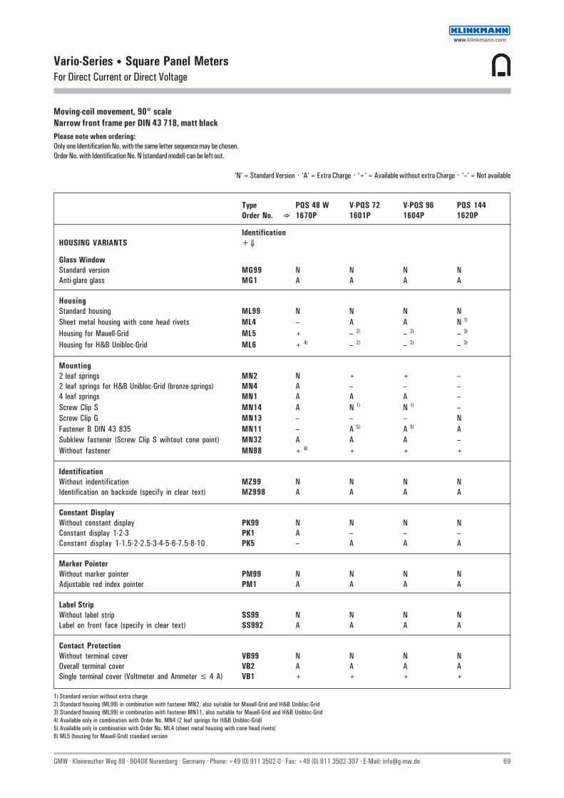
GMW · Kleinreuther Weg 88 · 90408 Nuremberg · Germany · Phone: +49 (0) 911 3502-0 · Fax: +49 (0) 911 3502-307 · E-Mail: [email protected] 69
Vario-Series • Square Panel MetersFor Direct Current or Direct Voltage
Moving-coil movement, 90° scaleNarrow front frame per DIN 43 718, matt blackPlease note when ordering:Only one Identification No. with the same letter sequence may be chosen.Order No. with Identification No. N (standard model) can be left out.
‘N’ = Standard Version · ‘A’ = Extra Charge · ‘+’ = Available without extra Charge · ‘–’ = Not available
Type PQS 48 W V-PQS 72 V-PQS 96 PQS 144Order No. ⇒ 1670P 1601P 1604P 1620P
IdentificationHOUSING VARIANTS +⇓
Glass WindowStandard version MG99 N N N NAnti-glare glass MG1 A A A A
HousingStandard housing ML99 N N N NSheet metal housing with cone head rivets ML4 – A A N 1)
Housing for Mauell-Grid ML5 + – 2) – 2) – 3)
Housing for H&B Unibloc-Grid ML6 + 4) – 2) – 2) – 3)
Mounting2 leaf springs MN2 N + + –2 leaf springs for H&B Unibloc-Grid (bronze-springs) MN4 A – – –4 leaf springs MN1 A A A –Screw Clip S MN14 A N 1) N 1) –Screw Clip G MN13 – – – NFastener B DIN 43 835 MN11 – A 5) A 5) ASubklew fastener (Screw Clip S wihtout cone point) MN32 A A A –Without fastener MN88 + 6) + + +
IdentificationWithout indentification MZ99 N N N NIdentification on backside (specify in clear text) MZ998 A A A A
Constant DisplayWithout constant display PK99 N N N NConstant display 1-2-3 PK1 A – – –Constant display 1-1.5-2-2.5-3-4-5-6-7.5-8-10 PK5 – A A A
Marker PointerWithout marker pointer PM99 N N N NAdjustable red index pointer PM1 A A A A
Label StripWithout label strip SS99 N N N NLabel on front face (specify in clear text) SS992 A A A A
Contact ProtectionWithout terminal cover VB99 N N N NOverall terminal cover VB2 A A A ASingle terminal cover (Voltmeter and Ammeter ≤ 4 A) VB1 + + + +
1) Standard version without extra charge2) Standard housing (ML99) in combination with fastener MN2, also suitable for Mauell-Grid and H&B Unibloc-Grid3) Standard housing (ML99) in combination with fastener MN11, also suitable for Mauell-Grid and H&B Unibloc-Grid4) Available only in combination with Order No. MN4 (2 leaf springs for H&B Unibloc-Grid)5) Available only in combination with Order No. ML4 (sheet metal housing with cone head rivets)6) ML5 (housing for Mauell-Grid) standard version
wwwwww.klinkmann.com

70 GMW · Kleinreuther Weg 88 · 90408 Nuremberg · Germany · Phone: +49 (0) 911 3502-0 · Fax: +49 (0) 911 3502-307 · E-Mail: [email protected]
Vario-Series • Square Panel MetersFor Direct Current or Direct Voltage
Moving-coil movement, 240° scaleNarrow front frame per DIN 43 718, matt black
V-PQ 96-250Technical Data
Front Dimensions mm 48 x 48 72 x 72 96 x 96 144 x 144Type V-PQ 48-250 V-PQ 72-250 V-PQ 96-250 PQ 144-250
Scale Length mm 73 113 151 235Class 1.5 1.5 1.5 1.5Weight approx. (kg) 0.16 0.2 0.25 0.65Operating Voltage 300 V 600 V 600 V 600 VTest Voltage 3.5 kV 5.8 kV 5.8 kV 5.8 kV Front Housing-Panel Protection IP 52 IP 52 IP 52 IP 52 Fasteners (see next page) leaf spring screw clip S screw clip S screw clip G Housing Material polycarbonate polycarbonate polycarbonate sheet metal Interchangeable Scale yes yes yes no
DescriptionAnalog panel meter with moving-coil movement
DisplayScale Division Coarse-finepointer Beam pointer with knife-edge
Mechanical DesignHousing Material Polycarbonate, self-extinguishing and drip-proof per UL 94 V - 0
or sheet metal housing (see above).Sheet metal housing available as option for type V-PQS 72 andV-PQS 96
Replaceable Glass windows, front frames and scales (interchangeablescales not available for panel meters with front paneldimensions of 144 x 144 mm)⇒ May only be replaced under voltage-free conditions!
Terminals M4 (Voltmeter and Ammeter ≤ 4 A) orM6 (Voltmeter >4 A).M4 screw terminals with self-lifting terminal clips. Screwscan be turned with a cross-head or standard screw drivers
Contact Protection Available as option
Reference Conditions
Reference Quantities Reference Conditions
Ambient Temperature 23 °C ± 2 °CPosition of Use control panel vertical ±1°Other DIN EN 60 051
Internal Resistance / Voltage Drop / Current Consumption 1)
Measuring Range Ri Tolerance
100 µA 10300 Ω150 µA 8210 Ω250 µA 2870 Ω400 µA 1770 Ω600 µA 773 Ω
1 mA 337 Ω1.5 mA 167 Ω ±20 %2 mA 97 Ω2.5 mA 52 Ω4 mA 25 Ω5 mA 16.3 Ω6 mA 14.2 Ω
10 mA 3 Ω15 mA 6.5 Ω20 mA 5 Ω ±30 %4 ... 20 mA 6.5 Ω25 mA 6 Ω
> 25 mA Voltage Drop 150 mV Connection to Shunt Current Consumption 10 mA
150 mV 75 Ω250 mV 125 Ω400 mV 200 Ω ±20 %600 mV 300 Ω
≥ 1 V 1000 Ω/V
1) Indicated internal resistance is only valid for instruments with standard accuracy class.Please inquire regarding internal resistance (Ri) for moving-coil indicators with mechanical zeropoint at any desired scale value.
wwwwww.klinkmann.com

GMW · Kleinreuther Weg 88 · 90408 Nuremberg · Germany · Phone: +49 (0) 911 3502-0 · Fax: +49 (0) 911 3502-307 · E-Mail: [email protected] 71
Vario-Series • Square Panel MetersFor Direct Current or Direct Voltage
Leaf Spring
Control panel thickness 1 to 3 mm.For size 48 x 48 mm, not available for Mauell-Grid.Also available as option for sizes 72 x 72 and 96 x 96 mm.
Screw Clip G
Control panel thickness 1 to 32 mm.Special screw clamp M4 required for size 144 x 144 mm.
Basic Dimensions
Screw Clip S
Control panel thickness 1 to 25 mm.Special screw clamp M4 required for sizes 72 x 72 and 96 x 96 mm.Also available as option for size 48 x 48 mm, not available for Mauell-Grid.
Fastener B DIN 43 835
Control panel thickness 1 to 40 mm.Screw clamp M4 as option for: Sheet metal housings 72 x 72 and 96 x 96 mm with cone head rivets and size 144 x 144 mm.
Drawings to Scale (on request)0101A258 for size 48 x 48 mm0101A259 for sizes 72 x 72 and 96 x 96 mm0101A261 sheet 1 for size 144 x 144 mm
Ordering ExamplePanel meter 96 x 96 mm240° Scale0 ... 40 V Direct Voltage
Type Order No. V-PQ 96-250 1605P, DC40
Front Dimensions Nominal Dimensions Cutout Dimensions Installation Depth Terminals mm
≤ 4 A > 4 A
M4 M6a1 x a2 h l1 x l2 t e e
48 x 48 48 x 48 5 45+0.6 x 45+0.6 43.5 12.5 — 72 x 72 72 x 72 5 68+0.7 x 68+0.7 43.5 12.5 17 96 x 96 96 x 96 5 92+0.8 x 92+0.8 43.5 12.5 18 144 x 144 144 x 144 8 138+1 x 138+1 44.5 12.5 18
1) Single terminal cover2) Overall terminal cover (22 mm for panel meters with front panel dimensions of 48 x 48 mm only)
wwwwww.klinkmann.com
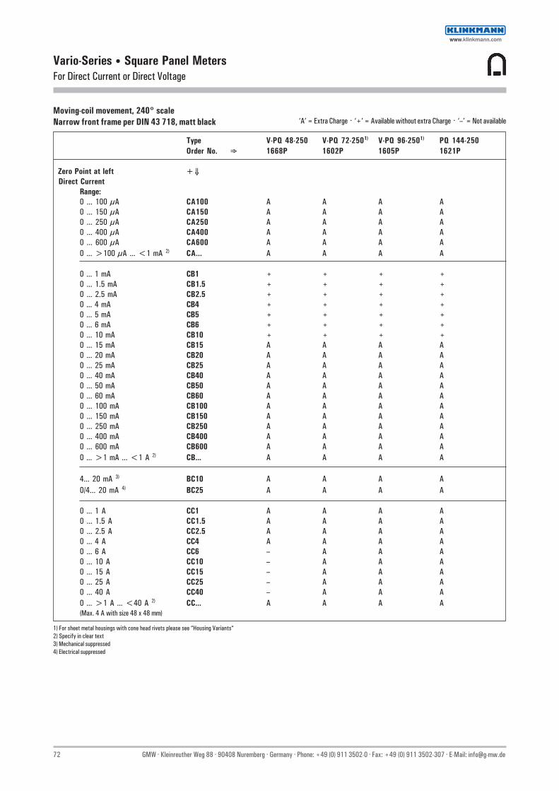
72 GMW · Kleinreuther Weg 88 · 90408 Nuremberg · Germany · Phone: +49 (0) 911 3502-0 · Fax: +49 (0) 911 3502-307 · E-Mail: [email protected]
Vario-Series • Square Panel MetersFor Direct Current or Direct Voltage
Moving-coil movement, 240° scaleNarrow front frame per DIN 43 718, matt black ‘A’ = Extra Charge · ‘+’ = Available without extra Charge · ‘–’ = Not available
Type V-PQ 48-250 V-PQ 72-2501) V-PQ 96-2501) PQ 144-250Order No. ⇒ 1668P 1602P 1605P 1621P
Zero Point at left +⇓ Direct Current
Range:0 ... 100 µA CA100 A A A A0 ... 150 µA CA150 A A A A0 ... 250 µA CA250 A A A A0 ... 400 µA CA400 A A A A0 ... 600 µA CA600 A A A A0 ... >100 µA ... <1 mA 2) CA... A A A A
0 ... 1 mA CB1 + + + +0 ... 1.5 mA CB1.5 + + + +0 ... 2.5 mA CB2.5 + + + +0 ... 4 mA CB4 + + + +0 ... 5 mA CB5 + + + +0 ... 6 mA CB6 + + + +0 ... 10 mA CB10 + + + +0 ... 15 mA CB15 A A A A0 ... 20 mA CB20 A A A A0 ... 25 mA CB25 A A A A0 ... 40 mA CB40 A A A A0 ... 50 mA CB50 A A A A0 ... 60 mA CB60 A A A A0 ... 100 mA CB100 A A A A0 ... 150 mA CB150 A A A A0 ... 250 mA CB250 A A A A0 ... 400 mA CB400 A A A A0 ... 600 mA CB600 A A A A0 ... >1 mA ... <1 A 2) CB... A A A A
4... 20 mA 3) BC10 A A A A0/4... 20 mA 4) BC25 A A A A
0 ... 1 A CC1 A A A A0 ... 1.5 A CC1.5 A A A A0 ... 2.5 A CC2.5 A A A A0 ... 4 A CC4 A A A A0 ... 6 A CC6 – A A A0 ... 10 A CC10 – A A A0 ... 15 A CC15 – A A A0 ... 25 A CC25 – A A A0 ... 40 A CC40 – A A A0 ... >1 A ... <40 A 2) CC... A A A A(Max. 4 A with size 48 x 48 mm)
1) For sheet metal housings with cone head rivets please see “Housing Variants“2) Specify in clear text3) Mechanical suppressed4) Electrical suppressed
wwwwww.klinkmann.com

GMW · Kleinreuther Weg 88 · 90408 Nuremberg · Germany · Phone: +49 (0) 911 3502-0 · Fax: +49 (0) 911 3502-307 · E-Mail: [email protected] 73
Vario-Series • Square Panel MetersFor Direct Current or Direct Voltage
Moving-coil movement, 240° scaleNarrow front frame per DIN 43 718, matt black ‘A’ = Extra Charge · ‘+’ = Available without extra Charge · ‘–’ = Not available
Type V-PQ 48-250 V-PQ 72-2501) V-PQ 96-2501) PQ 144-250Order No. ⇒ 1668P 1602P 1605P 1621P
Zero Point at left +⇓ Connection to shunt (direct current)
... A / 60 mV BE3 + + + A
... A / 150 mV BE4 + + + A
... A / ...>60 mV 2) BE981 A A A AScale:1 A CG1 + + + +1.5 A CG1.5 + + + +2.5 A CG2.5 + + + +4 A CG4 + + + +6 A CG6 + + + +10 A CG10 + + + +15 A CG15 + + + +25 A CG25 + + + +40 A CG40 + + + +60 A CG60 + + + +100 A CG100 + + + +150 A CG150 + + + +250 A CG250 + + + +400 A CG400 + + + +500 A CG350 + + + +600 A CG600 + + + +0 ...>1 A<1 kA 3) CG... + + + +
1 kA CH1 + + + +1.5 kA CH1.5 + + + +2.5 kA CH2.5 + + + +4 kA CH4 + + + +5 kA CH5 + + + +6 kA CH6 + + + +10 kA CH10 + + + +15 kA CH15 + + + +>1 kA 2) CH... + + + +
Direct VoltageRange:0 ... 150 mV DB150 A A A A0 ... 250 mV DB250 A A A A0 ... 400 mV DB400 A A A A0 ... 600 mV DB600 A A A A0 ...>150 mV ...<1 V 3) DB... A A A A
0 ... 1 V DC1 A A A A0 ... 1.5 V DC1.5 A A A A0 ... 2.5 V DC2.5 A A A A0 ... 3 V DC3 A A A A0 ... 4 V DC4 A A A A0 ... 6 V DC6 A A A A0 ... 10 V DC10 A A A A0 ... 15 V DC15 A A A A0 ... 25 V DC25 A A A A0 ... 40 V DC40 A A A A0 ... 60 V DC60 A A A A0 ... 100 V DC100 A A A A0 ... 150 V DC150 A A A A0 ... 250 V DC250 A A A A0 ... 400 V DC400 — A A A0 ... 500 V DC500 — A A A0 ... 600 V DC600 — A A A0 ...>1 V ...<600 V 3) 4) DC... — A A A
Connection to separate voltage divider 5)
... kV / 25 V (250 µA) BE76 A A A A
1) For sheet metal housings with cone head rivets please see „Housing Variants“ 4) Higher Voltages - see voltage deviders, page 1292) Upper value>60 mV 5) Voltage dividers - see page 1293) Specify in clear text
wwwwww.klinkmann.com

74 GMW · Kleinreuther Weg 88 · 90408 Nuremberg · Germany · Phone: +49 (0) 911 3502-0 · Fax: +49 (0) 911 3502-307 · E-Mail: [email protected]
Vario-Series • Square Panel MetersFor Direct Current or Direct Voltage
Moving-coil movement, 240° scaleNarrow front frame per DIN 43 718, matt blackPlease note when ordering:Only one Identification No. with the same letter sequence may be chosen.Order No. with Identification No. N (standard model) can be left out.
‘N’ = Standard Version · ‘A’ = Extra Charge · ‘+’ = Available without extra Charge · ‘–’ = Not available
Type V-PQ 48-250 V-PQ 72-250 V-PQ 96-250 PQ 144-250Order No. ⇒ 1668P 1602P 1605P 1621P
IdentificationGENERAL VARIANTS +⇓
Zero PointZero point at left BC1 N N N NZero point at center BC2 A A A AZero point as desired (specify in clear text) BC20 A A A AZero point at left, mech. suppressed (not 4-20 mA) BC16 A A A A(Max. Suppression 20%; measuring ranges≥250 µA / ≥250 mV, Ri 1kΩ/V; specify in clear text)
Internal Resistance with VoltmetersStandard (see technical data) IR99 N N N NRi approx. 10 kΩ/V (measuring input ≥ 4 V) IR10 A A A ARi = 1 kΩ / V ±1 % at nominal temperature IR30 A A A A
(measuring input ≥ 1 V)Ri = 10 kΩ/V ±1 % at nominal temperature IR53 A A A A
(measuring input ≥ 4 V)
Potentiometer for Adjustment with VoltmetersVoltmeters without potentiometer for adjustment MP99 N N N NVoltmeters with potentiometer for adjustment MP1 – A A AAdjustment range ±15 % (Measuring input ≥ 6 V / ≤ 550 V;Ri as listed; Class 1.5 only)
Lead Resistor when connecting toShunt Resistors ...A / 60 mV and ...A / 150 mVStandard version 0.06 Ω IG99 N N N NDiffering from 0.06 Ω (specify in clear text) IG999 A A A ALimiting values: ...A / 60 mV for class 1.5 max. 1 Ω
...A / 150 mV in Klasse 1.5 max. 7 Ω
AccuracyClass 1.5 IE15 N N N NClass 1.0 (Measuring input ≥ 100 µA / ≥ 60 mV; IE11 – A A Awith 72 x 72 in combination with fine division andbeam pointer with knife-edge only)
Position of UseControl panel vertical LA1 N N N NControl panel horizontal LA2 + + + +Other LA999 A A A A(Please specify angle between scale and horizontal)
Special FeaturesNormal vibration and shock resistance LN99 N N N NSuitable for marine use with the following approvals:Germanischer Lloyd LN2 A A A ABV 0591 German Navy LN1 – + 1) + 1) ABV 3340 German Navy LN6 – – 2) – 3) + 4)
Vibration resis. 2.5 g, Shock resis. 30 g LN56 A 5) A A AVibration resis. 5 g, Shock resis. 50 g LN55 A 5) A A A 6)
1) Contains sheet metal housing with cone head rivets (Ident. ML4) and fastener B (Ident. MN11)2) Type PQS 72-250 according to special data sheet3) Type PQS 96-250 according to special data sheet4) See special data sheet5) Available only in combination with screw clip S6) Available only in combination with fastener B DIN 43835
onrequest
Class 1.5 onlymeasuring input≥ 250 µA≥ 250 mVConnectionto shunt≥ 60 mV
wwwwww.klinkmann.com

GMW · Kleinreuther Weg 88 · 90408 Nuremberg · Germany · Phone: +49 (0) 911 3502-0 · Fax: +49 (0) 911 3502-307 · E-Mail: [email protected] 75
Vario-Series • Square Panel MetersFor Direct Current or Direct Voltage
Moving-coil movement, 240° scaleNarrow front frame per DIN 43 718, matt blackPlease note when ordering:Only one Identification No. with the same letter sequence may be chosen.Order No. with Identification No. N (standard model) can be left out.
‘N’ = Standard Version · ‘A’ = Extra Charge · ‘+’ = Available without extra Charge · ‘–’ = Not available
Type V-PQ 48-250 V-PQ 72-250 V-PQ 96-250 PQ 144-250Order No. ⇒ 1668P 1602P 1605P 1621P
IdentificationSCALE VARIANTS +⇓
ScaleIn accordance with measuring input GF99 N N N NBlank Scale (lower/upper value markings, GF28 + + + +
company logos, symbols)Scale CharacteristicsCurrent / Voltage linear SD1 N N N NAccording to curve (not current / voltage linear) SD6 A A A A
Division and PointerSingle division GD1 N N N NDouble division GD2 A A A ACoarse-fine division SE1 N N N NFine division SE3 – A A ABeam pointer with for single division RA1 N N N Nknife-edge for double division RA2 + + + +Knife-edge pointer for single division RA10 A A A A
for double division RA11 — A A ABar indicator for single division RA40 A A A A
Additional ImprintSecond numbering (specify in clear text) SK992 A A A AInscription:Without additional inscription SM99 N N N NInscription ≤ 15 characters German SM991 A A A A
>15 characters German SM992 A A A A≤ 15 characters other language SM993 A A A A>15 characters other language SM994 A A A A
(Other language in Latin lettering. specify in clear text)Coloured mark red RAL 2002 (specify in clear text) ST991 A A A AColoured sectors yellow RAL 1021. green RAL 6018or red RAL 2002 (specify in clear text) SU991 A A A A
Scale CharacteristicsInterchangeable scale SA10 N N N –Screw mounted scale SA11 A A A N1)
Anti-parallax scale (with bar indicator and single division) SA5 A A A A
1) Standard version without extra charge
wwwwww.klinkmann.com

76 GMW · Kleinreuther Weg 88 · 90408 Nuremberg · Germany · Phone: +49 (0) 911 3502-0 · Fax: +49 (0) 911 3502-307 · E-Mail: [email protected]
Vario-Series • Square Panel MetersFor Direct Current or Direct Voltage
Moving-coil movement, 240° scaleNarrow front frame per DIN 43 718, matt blackPlease note when ordering:Only one Identification No. with the same letter sequence may be chosen.Order No. with Identification No. N (standard model) can be left out.
‘N’ = Standard Version · ‘A’ = Extra Charge · ‘+’ = Available without extra Charge · ‘–’ = Not available
Type V-PQ 48-250 V-PQ 72-250 V-PQ 96-250 PQ 144-250Order No. ⇒ 1668P 1602P 1605P 1621P
IdentificationSCALE VARIANTS +⇓
Scale / Pointer ColoursScale white; imprint and pointer black SG99 N N N NScale balck; imprint and pointer white SG1 A 1) A 1) A 1) A 1)
Scale black; imprint and pointer yellow SG2 A 1) A 1) A 1) A 1)
Scale black; imprint white, pointer yellow SG3 A 1) A 1) A 1) A 1)
Without scale; pointer black SG10 + + + –Without scale; pointer white SG11 A A A –Without scale; pointer yellow SG12 A A A –Versions without scales available only for panel meters thatare connected to transformers or shunts
Dial IlluminationWithout dial illumination PA99 N N N NWith direct dial illumination PA1 – A A A(Plexiglass scale, scale and dial illumination white)Note: Completion with Voltage Order No. PB... necessary.Size 48 x 48: dial illumination available only for ≤ 4 A / ≤ 660 Vtogether with single terminal cover.With indirect dial illumination:Light conductor with mask, dial illumination white PA6 – A A ALight conductor with mask, dial illumination red PA7 – A A ANote: Completion with Voltage Order No. PB... and SG necessary(SG 99 as light conductor with mask not available).Dial illumination available only with screw mounted scale (Order No. SA11)
Voltage for Dial Illumination12 V PB3 – + + +24 V PB5 – + + +28 V PB6 – + + +
HOUSING VARIANTS
ApplicationStandard version LB99 N N N NTropic resistant LB1 A A A A
ProtectionStandard (see technical data) LH99 N N N NFront housing-panel protection IP54. clamps IP00 LH21 A A A AEarthquake-proof (possible combination: LH99 or LH21) LH10 A A A A
Front Frame ColourMatt black MA2 N N N NMatt grey RAL 7037 MA11 A A A AMatt stone grey RAL 7032 MA12 A A A AMatt light grey RAL 7035 MA14 A A A –Matt dark beige approx. RAL 1019 MA21 A A A A
Intermediate Frame, Height 3 mmWithout intermediate frame MC99 N N N NIntermediate frame shiny black MC1 A A A –Intermediate frame shiny grey RAL 7037 MC2 A A A AIntermediate frame available only in combination with screw clip S or fastener B DIN 43 835
1) Additional one-off costs for special scale printing on request
wwwwww.klinkmann.com

GMW · Kleinreuther Weg 88 · 90408 Nuremberg · Germany · Phone: +49 (0) 911 3502-0 · Fax: +49 (0) 911 3502-307 · E-Mail: [email protected] 77
Vario-Series • Square Panel MetersFor Direct Current or Direct Voltage
Moving-coil movement, 240° scaleNarrow front frame per DIN 43 718, matt blackPlease note when ordering:Only one Identification No. with the same letter sequence may be chosen.Order No. with Identification No. N (standard model) can be left out.
‘N’ = Standard Version · ‘A’ = Extra Charge · ‘+’ = Available without extra Charge · ‘–’ = Not available
Type V-PQ 48-250 V-PQ 72-250 V-PQ 96-250 PQ 144-250Order No. ⇒ 1668P 1602P 1605P 1621P
IdentificationHOUSING VARIANTS +⇓
Glass WindowStandard version MG99 N N N NAnti-glare glass MG1 A A A A
HousingStandard housing ML99 N N N NSheet metal housing with cone head rivets ML4 – A A N 1)
Housing for Mauell-Grid ML5 + – 2) – 2) – 3)
Housing for H&B Unibloc-Grid ML6 + 4) – 2) – 2) – 3)
Mounting2 leaf springs MN2 N + + –2 leaf springs for H&B Unibloc-Grid (bronze-springs) MN4 A – – –4 leaf springs MN1 A A A –Screw Clip S MN14 A N 1) N 1) –Screw Clip G MN13 – – – NFastener B DIN 43 835 MN11 – A 5) A 5) ASubklew fastener (Screw Clip S without cone point) MN32 A A A –Without fastener MN88 + 6) + + +
IdentificationWithout Identification MZ99 N N N NIdentification on backside (specify in clear text) MZ998 A A A A
Marker PointerWithout marker pointer PM99 N N N NAdjustable red index pointer PM1 A A A
Label StripWithout label strip SS99 N N N NLabel on front face (specify in clear text) SS992 A A A A
Contact ProtectionWithout terminal cover VB99 N N N NOverall terminal cover VB2 A A A ASingle terminal cover (Voltmeter and Ammeter ≤ 4 A) VB1 + + + +
1) Standard version without extra charge2) Standard housing (ML99) in combination with fastener MN2, also suitable for Mauell-Grid and H&B Unibloc-Grid3) Standard housing (ML99) in combination with fastener MN11, also suitable for Mauell-Grid and H&B Unibloc-Grid4) Available only in combination with Order No. MN4 (2 leaf springs for H&B Unibloc-Grid)5) Available only in combination with Order No. ML4 (sheet metal housing with cone head rivets)6) ML5 (housing for Mauell-Grid) standard version
wwwwww.klinkmann.com

78 GMW · Kleinreuther Weg 88 · 90408 Nuremberg · Germany · Phone: +49 (0) 911 3502-0 · Fax: +49 (0) 911 3502-307 · E-Mail: [email protected]
Vario-Series • Square Panel MetersFor Active Power or Reactive Power
Moving-coil movement with power converter, 90° or 240° scaleNarrow front frame per DIN 43 718, matt black
Technical Data
Front Dimensions mm 96 x 96 96 x 96Type V-LM 96 V-LM 96-250
Scale Length mm 97 151Accuracy Class 1.5 1.5Max. Weight (standard model), kg 0.8 0.8Power Consumption approx.
- Current Path 0.2 VA 0.2 VA- Voltage Path Order No.: AB1 / AB2 / AB12 / AB5 / AB15 3 VA 3 VA
AB11 3.5 VA 3.5 VAAB4 / AB14 3.4 VA 3.4 VAAB6 3.9 VA 3.9 VAAB16 4.3 VA 4.3 VA
Nominal Supply Voltage: Outer to Neutral Conducter (= Operating Voltage) ≤ 398 V3-Phase-3-Wire-Systems ≤ 690 V3-Phase-4-Wire-Systems ≤ 398 / 690 VOperating Voltage 600 V 600 VTest Voltage 5.8 kV 5.8 kVFront Housing-Panel Protection IP 52 IP 52
DescriptionAnalog panel meter with core-magnet moving-coil movement and built in powerconverter for active and reactive power.Depending upon type of system and power, the power converter consists of one,two or three multipliers. The multipliers function in accordance with theTDM process (time division muliplier). The output signals from the multipliers areadded and fed to the moving coil mechanism.
DisplayScale Division Coarse-finePointer Beam pointer with knife-edge
Mechanical DesignHousing Material Polycarbonate, self-extinguishing and drip-proof per UL 94V-0Mounting Fasteners Standard: Screw Clip S
Alternative: Subklew fastenersReplaceable Scales, glass windows and front frames
⇒ May only be replaced under voltage-free conditions!
Terminals M4 screw terminals with self-lifting terminal clips. Screwscan be turned with a cross-head or standard screw drivers
Clamp Indentification per DIN 43807Contact Protection Finger-safe full cover included
V-LM 96
V-LM 96-250
Reference Conditions
Reference Quantities Reference Conditions
Ambient Temperature 23 °C± 2 °C Position of Use control panel vertical ± 1° Frequency 45 ... 65 Hz Current Component 20 ...120 % of rated value Voltage Component 98 ... 102 % of rated value Warm-up Time ≥ 5 min. Other DIN EN 61010-1
Notes Concerning the Determination of Measuring RangesThe upper measuring value should be a standard value per DIN 43 70:
1 — 1.2 — 1.5 — 2 — 2.5 — 3 — 4 — 5 — 6 — 7.5 — 8and corresponding powers of ten.The upper measuring range value must lie within a range of 0.5 to 1.2 times apparentpower.Apparent power PS is calculated from the primary values from the current and voltagetransformers:
• Single-Phase AC PS = U x I• Three-Phase PS = U x I x √3
where U equals phase-to-phase voltage.
wwwwww.klinkmann.com

GMW · Kleinreuther Weg 88 · 90408 Nuremberg · Germany · Phone: +49 (0) 911 3502-0 · Fax: +49 (0) 911 3502-307 · E-Mail: [email protected] 79
Vario-Series • Square Panel MetersFor Active Power or Reactive Power
Schematic Diagrams
Basic Dimensions
Front Dimensions Nominal Dimen. mm Cutout Dimensions mm Order No. Installation Depth mm mm a1 x a2 h I1 x I2 incl. Terminals t incl. Full Cover f
AB1/AB11/AB2/AB12/ 96 x 96 96 x 96 5 92+0.8 x 92+0.8 AB4/AB14/AB5/AB15/ 117 123
AB6/AB16
Single-Phase Alternating CurrentActive & Reactive Power
3-Phase 3- Wire, Balanced LoadActive Power
3-Phase 3-Wire, Balanced LoadActive & Reactive Power
3-Phase 3-Wire, Balanced LoadReactive Power
3-Phase 4-Wire, Balanced LoadActive Power
3-Phase 4-Wire, Balanced LoadReactive Power
3-Phase 4-Wire, Unbalanced LoadActive & Reactive Power
wwwwww.klinkmann.com

80 GMW · Kleinreuther Weg 88 · 90408 Nuremberg · Germany · Phone: +49 (0) 911 3502-0 · Fax: +49 (0) 911 3502-307 · E-Mail: [email protected]
Vario-Series • Square Panel MetersFor Active Power or Reactive Power
Moving-coil movement with power converter, 90° or 240° scaleNarrow front frame per DIN 43 718, matt black
Type V-LM 96 V-LM 96-250Order No. ⇒ 1129D 1115D+⇓ +⇓ +⇓
System Type / Power Type Voltage Path Terminal2-Wire-SystemActive Power, Single Phase AC AB1 + +
to transf. sec.: 100 V primary voltage: ... V BF12 DG... + +primary voltage: ... kV BF12 DH... + +
to transf. sec.: 110 V primary voltage: ... V BF15 DG... + +primary voltage: ... kV BF15 DH... + +
direct 230 V AC IL323 + +direct 240 V AC IL324 + +direct 400 V AC IL340 + +
Reactive Power, Single Phase AC AB11 A A
direct 230 V AC IL323 + +direct 240 V AC IL324 + +direct 400 V AC IL340 + +
3-Wire-SystemActive Power, 3-Wire Balanced Load AB2 A AReactive Power, 3-Wire Balanced Load AB12 A AActive Power, 3-Wire Unbalanced Load AB4 A AReactive Power, 3-Wire Unbalanced Load AB14 A A
to transf. sec.: 100 V primary voltage: ... V BF12 DG... + +primary voltage: ... kV BF12 DH... + +
to transf. sec.: 110 V primary voltage: ... V BF15 DG... + +primary voltage: ... kV BF15 DH... + +
direct 400 V AC IL340 + +direct 415 V AC IL661 + +direct 440 V AC IL344 + +direct 500 V AC IL350 + +direct 690 V AC IL369 + +
4-Wire-SystemActive Power 4-Wire Balanced Load AB5 A AReactive Power 4-Wire Unbalanced Load AB15 A AActive Power 4-Wire Balanced Load AB6 A AReactive Power 4-Wire Unbalanced Load AB16 A A
to transf. sec.: 100 V primary voltage: ... V BF12 DG... + +primary voltage: ... kV BF12 DH... + +
to transf. sec.: 110 V primary voltage: ... V BF15 DG... + +primary voltage: ... kV BF15 DH... + +
direct 230 / 400 V AC IL723 + +direct 240 / 415 V AC IL721 + +direct 254 / 440 V AC IL722 + +direct 277 / 480 V AC IL724 + +direct 398 / 690 V AC IL725 + +
Current Path Terminal to transf. sec.: 1 A primary current: ... A BE10 CG... + +primary current: ... kA BE10 CH... + +
to transf. sec.: 5 A primary current: ... A BE11 CG... + +primary current: ... kA BE11 CH... + +
Please note when ordering:Only one Order No. with the same letter sequence may be chosen. Order No. with Identification N (standard model) can be left out.An entry with “...“ in the Order No. column means that the Order No. must be supplemented with written text.
‘A’ = Extra Charge · ‘+’ = Available without extra Charge · ‘–’ = Not available
wwwwww.klinkmann.com

GMW · Kleinreuther Weg 88 · 90408 Nuremberg · Germany · Phone: +49 (0) 911 3502-0 · Fax: +49 (0) 911 3502-307 · E-Mail: [email protected] 81
Vario-Series • Square Panel MetersFor Active Power or Reactive Power
Moving-coil movement with power converter, 90° or 240° scaleNarrow front frame per DIN 43 718, matt black
Please note when ordering:Only one Order No. with the same letter sequence may be chosen. Order No. with Identification N (standard model) can be left out.An entry with “...“ in the Order No. column means that the Order No. must be supplemented with written text.
‘A’ = Extra Charge · ‘+’ = Available without extra Charge · ‘–’ = Not available
Type V-LM 96 V-LM 96-250Order No. ⇒ 1129D 1115D+⇓
Variants
Zero Point at left N Nat center BC2 A A10% of positive upper value BC6 A A
Upper value of meas. range (from 0.5 to 1.2 x of reactive power selectable) NB... + +
Scale Division corresponds to measuring range N Nblank scale (lower/upper val. markings, logos, sym.) GL98 + +
Position of Use standard N N0 ... 45 degrees from horizontal (bonded glass) LA11 A A46 ... 89 degrees from horizontal (bonded glass) LA12 A A91 ... 135 degrees from horizontal LA13 A A
Applications standard N Ntropic resistant, climatic category 3 LB4 A A
Protection standard N Nfront panel IP 54, terminals IP00 LH21 A A
Resistance to Vibration/ standard N N Marine Applications vibration resistance 2.5 g; shock resistance 30 g LN56 A A
marine applications, Germanischer Lloyd LN8 A A
Front Frame matt black N Nmatt grey, RAL 7037 MA11 A A
Glass Window standard N Nanti-glare MG1 A Aanti-glare, with red adjustable index pointer MG98 A A
Housing and Mounting standard N Npolycarbonate housing with Subklew fasteners ML10 A A
Identification none N Non the back: ............ MZ998... A A
Scale Inscription none N N(Latin lettering) ≤ 22 characters, 1 line: .......... SM902... A A
≤ 37 characters, 2 lines:1st line (15 characters): ...; 2nd line (22 char.): ... SM911... A A
Additional Numberings none N N2nd set of numbering black: ... SK982... A A2nd set of numbering red (RAL 2002): ... SK983... A A
Red Marker (RAL 2002) none N Nred marker at: ... ST981... A A
Ordering Example:Panel meter for active power for 3-wire-system with unbalanced load,Connection to transformer 100/5 A, 400 V, measuring range 0...60 kW, 240° Scale
Type Order No. V-LM 96-250 1115D, AB4, BE11, CG100, IL340, NB: 0...60 kW
wwwwww.klinkmann.com

82 GMW · Kleinreuther Weg 88 · 90408 Nuremberg · Germany · Phone: +49 (0) 911 3502-0 · Fax: +49 (0) 911 3502-307 · E-Mail: [email protected]
Vario-Series • Square Panel MetersFor Power Factor
Moving-coil movement with power factor converter, 90° scaleNarrow front frame per DIN 43 718, matt black
Technical Data
Front Dimensions 96 x 96 mmType V-LF 96
Scale Length mm 94Accuracy Class 1.5Max. Weight (standard version.), kg 0.54Power Consumprion approx. Current Path 1.0 VAVoltage Path 3.0 VAOperating Voltage: Outer to neutral conductor ≤ 300 V
3-Phase-3-Wire-System ≤ 500 V3-Phase-4-Wire-System ≤ 277 / 480 V
Test Voltage 3.5 kVFront Housing-Panel Protection IP 52
DescriptionAnalog panel meter with core-magnet moving-coil movement and built in power factorconverter. The power factor converter determines the phase angle between current andvoltage. cos ϕ is displayed at the moving-coil movement.
DisplayMeasuring Range CAP 0.5 ... 1 ... 0.5 INDScale Division Coarse-finePointer Beam pointer with knife edge
Mechanical DesignHousing Material Polycarbonate, self-extinguishing and drip-proof per UL94V-0
or sheet metal housing as optionMounting Fasteners Standard: Screw clip S.
Options: see next pageReplaceable Scales, front frames and glass windows
⇒ May only be replaced under voltage free conditions!Terminals M4 screw terminals with self-lifting terminal clips. Screws can
be turned with cross-head or standard screw drivers.Contact Protection Finger-safe full cover included
Basic Dimensions
Front in mm Nom. Dimensions. mm Cutout Dimensions. mm Installation Depth incl. Terminals M4 mm Installation Depth incl. Full cover. mma1 x a2 h I1 x I2 t f
96 x 96 96 x 96 5 92+0.8 x 92+0.8 124 (60 projected) 133
V-LF 96
Reference Conditions
Reference Quantities Reference Conditions
Ambient Temperature 23 °C ± 2°CPosition of Use control panel vertical ± 1 °Frequency 50 Hz ± 0.1 HzCurrent Component 95 ... 100% of rated valueVoltage Component 98 ... 102% of rated valueWaveshape sine, distortion factor ≤ 1%Warm-Up Time ≥ 5 min.Other DIN EN 60051
Nominal Range of Use Limits
Frequency 45 Hz ... 65 Hz49 Hz ... 51 Hz for Order No.: AB21
Schematic Diagrams
Single Phase Alternatig Current
3-Phase 3-Wire, Balanced Load
wwwwww.klinkmann.com

GMW · Kleinreuther Weg 88 · 90408 Nuremberg · Germany · Phone: +49 (0) 911 3502-0 · Fax: +49 (0) 911 3502-307 · E-Mail: [email protected] 83
Vario-Series • Square Panel MetersFor Power Factor
Moving-coil movement with power factor converter, 90° scaleNarrow front frame per DIN 43 718, matt black
Please note when ordering:Only one Order No. with the same letter sequence may be chosen. Order No. with Identification N (standard model) can be left out.An entry with “...“ in the Order No. column means that the Order No. must be supplemented with written text.
‘N’ = Standard Version · ‘A’ = Extra Charge · ‘+’ = Available without extra Charge · ‘–’ = Not available
Type V-LF 96Order No. ⇒ 1129H+⇓ +⇓
System Type / Power Type Nominal Voltage
Single Phase Alternating Current AB21 +
100 ... 110 V AC IL710 +220 ... 230 V AC IL726 +
3-Wire-System, Balanced Load AB22 +
100 ... 110 V AC IL710 +380 V AC IL338 +400 ... 500 V AC IL341 +
Current Path Terminal at transformer sec.: 1 A BE10 +at transformer sec.: 5 A BE11 +
Position of Use standard N0 ... 45 degrees from horizontal (bonded glass) LA11 A46 ... 89 degrees from horizontal (bonded glass) LA12 A91 ... 135 degrees from horizontal LA13 A
Application standard Nconditionally tropic resistant, climatic category 3 LB4 A
Protection standard Nfront panel: IP 54, terminals IP00 LH21 A
Resistance to Vibration/ standard NMarine Application vibration resistance 2.5 g; shock resistance 30 g LN56 A
Germanischer Lloyd LN8 A
Front Frame matt balck Nmatt grey, RAL 7037 MA11 A
Glass Window standard Nanti-glare MG1 Aanti-glare, with red adjustable set pointer MG98 A
Housing and Fasteners standard Nsheet metal housing with type S screw clip ML7 Asheet metal housing with type B screw clip ML8 Apolycarbonate housing with 2 leaf springs ML9 Apolycarbonate housing with 4 leaf springs ML11 Apolycarbonate housing with Subklew fasteners ML10 A
Identification none Non the back: ... MZ998... A
Scale Inscription none N(Latin lettering) ≤ 22 characters, 1 line: ... SM902... A
≤ 37 characters, 2 lines: 1st line (15 characters): ...2nd line (22 characters): ... SM911... A
Red Marker (RAL 2002) none Nred marker at: ... ST981... A
Ordering ExamplePanel meter for power factor3-Wire-System, balanced load, Type Order No.Connection to transformer sec. 5 A, 500 V V-LF 96 1129H, AB22, BE11, IL341
wwwwww.klinkmann.com

84 GMW · Kleinreuther Weg 88 · 90408 Nuremberg · Germany · Phone: +49 (0) 911 3502-0 · Fax: +49 (0) 911 3502-307 · E-Mail: [email protected]
Vario-Series • Square Panel MetersFor Frequency (Pointer-Type)
Moving-coil movement with frequency converter, 90° scaleNarrow front frame per DIN 43 718, matt black
V-FZQS 96Technical Data
Front Dimensions mm 48 x 48 72 x 72 96 x 96 Type FZQS 48 W V-FZQS 72 V-FZQS 96
Scale Length mm 40 66 94 Accuracy Class 0.5 0.5 0.5 Weight approx. (kg) 0.08 1) 0.2 0.25 Operating Voltage 300 V 600 V 600 V Test Voltage 3.5 kV 5.8 kV 5.8 kV Front Housing-Panel Protection IP 52 IP 52 IP 52 Fasteners (see next page) leaf spring screw clip S screw clip S Housing Material polycarbonate polycarbonate polycarbonate Interchangeable Scale yes yes yes Frequency Converter separate built in built in
1) plus 0.2 kg (approx.) for separated frequency converter
DescriptionAnalog panel meter with moving-coil movement and built in or separate frequencyconverter (see above)
DisplayScale Division Coarse-finePointer Beam pointer with knife edge
Mechanical DesignHousing Material Polycarbonate, self-extinguishing and drip-proof per UL 94 V - 0
or sheet metal housing (see above).Sheet metal housing for type V-ZQS 72 and V-ZQS 96 asoption.
Replaceable Scales, glass windows and front frames⇒ May only be replaced under
voltage-free conditions!Terminals M4 screw terminals with self-lifting terminal clips. Screws can
be turned with cross-head or standard screw drivers.Contact Protection Available as option
Reference Conditions
Reference Quantities Reference Conditions
Ambient Temperature 23 °C ± 2 °C Position of Use control panel vertical ±1° Other DIN EN 60 051
wwwwww.klinkmann.com

GMW · Kleinreuther Weg 88 · 90408 Nuremberg · Germany · Phone: +49 (0) 911 3502-0 · Fax: +49 (0) 911 3502-307 · E-Mail: [email protected] 85
Vario-Series • Square Panel MetersFor Frequency (Pointer-Type)
Leaf Spring
Control panel thickness 1 to 3 mm.For size 48 x 48 mm, not available for Mauell-Grid.Also available as option for sizes 72 x 72 and 96 x 96 mm.
Screw Clip S
Control panel thickness 1 to 25 mm.Special screw clamp M4 required for sizes 72 x 72 and 96 x 96 mm.Also available as option for size 48 x 48 mm, not available for Mauell-Grid.
Fastener B DIN 43 835
Control panel thickness 1 to 40 mm.Screw clamp M4 as option for: Sheet metal housings 72 x 72 and 96 x 96 mm with cone head rivets
Drawings to Scale (on request)0101A258 for size 48 x 48 mm0101A259 for sizes 72 x 72 and 96 x 96 mm1325A10 for separated measuring converter1402A32 for separated series resistance
Ordering ExamplePanel meter for frequency (pointer-type) , size 96 x 96 mm90° ScaleNominal Voltage 230 V, Class 0.5Measuring Range 45 ... 50 ... 55 Hz
Type Order No. V-FZQS 96 1604Z, IL323, EH619
Dimensions for separated Measuring Converter(for size 48 x 48 only)120 x 63 x 88 (B/T/H)Drawing to scale No. 1325 A 10 (on request)
Dimensions for separated Series Resistance90 x 36 x 35.5 (L x B x H)Drawing to scale No. 1402 A 32 (on request)
Front in mm Nominal Dimensions Cutout Dimensions Installation Depth TerminalsM4
a1 x a2 h l1 x l2 t e
48 x 48 48 x 48 5 45+0.6 x 45+0.6 43.5 12.5 72 x 72 72 x 72 5 68+0.7 x 68+0.7 43.5 12.5 96 x 96 96 x 96 5 92+0.8 x 92+0.8 43.5 12.5
1) Single terminal cover2) Overall terminal cover (22 mm for panel meters with front panel dimensions of 48 x 48 mm only)
Basic Dimensions
wwwwww.klinkmann.com

86 GMW · Kleinreuther Weg 88 · 90408 Nuremberg · Germany · Phone: +49 (0) 911 3502-0 · Fax: +49 (0) 911 3502-307 · E-Mail: [email protected]
Vario-Series • Square Panel MetersFor Frequency (Pointer Type)
Moving-coil movement with frequency converter, 90° scaleNarrow front frame per DIN 43 718, matt black ‘A’ = Extra Charge · ‘+’ = Available without extra Charge · ‘–’ = Not available
Type FZQS 48 W1) V-FZQS 722) V-FZQS 962)
Order No. ⇒ 1670Z 1601Z 1604Z
General Value Measuring +⇓ +⇓
Nominal Voltage3) 100–120 V IL731208–250 V IL732380–500 V IL733
Measuring Range Class48 ... 50 ... 52 Hz 4) 0.5 EH623 + + +58 ... 60 ... 62 Hz 4) 0.5 EH629 + + +380 ... 400 ... 420 Hz 4) 0.5 EH674 + + +45 ... 50 ... 55 Hz 5) 0.5 EH619 + + +55 ... 60 ... 65 Hz 5) 0.5 EH626 + + +90 ... 100 ... 110 Hz 5) 0.5 EH675 + + +180 ... 200 ... 220 Hz 5) 0.5 EH635 + + +270 ... 300 ... 330 Hz 5) 0.5 EH638 A A A360 ... 400 ... 440 Hz 5) 0.5 EH642 + A +15 ... 16.66 ... 18.4 Hz 5) 0.5 EH617 A A A45 ... 50 ... 60 ... 65 Hz 5) 1 EH671 + A +40 ... 50 ... 60 Hz 5) 1 EH618 A A A
For static TransducersNominal Voltage 60 ... 150 ... 230 ... 300 V IL734
Measuring Range300 ... 500 ... 750 Hz EH641 – – A600 ... 1000 ... 1400 Hz EH646 – – A1 ... 2 ... 3 kHz EK601 – – A1.8 ... 3 ... 4.2 kHz EK603 – – A2 .. 6 ... 10 kHz EK609 – – A6 ... 8 ... 10 kHz EK608 – – A
Wide RangeNominal Voltage 3) 100–120 V IL731
208–250 V IL732380–500 V IL733
Measuring Range Class0/10 ... 100 Hz 1.5 EH611 – – A0/10 ... 500 Hz 1.5 EH615 – – A0/0.1 ... 1 kHz 1.5 EK110 – – A0/0.1 ... 10 kHz 1.5 EK210 – – A
Class 1.5 for 150 ... 250 VClass 2.5 for < 150 ... 60 V and
> 250 ... 300 V
1) Separated measuring converter2) For sheet metal housings with cone head rivets please see “Housing Variants“3) Occuring voltage fluctuations up to ±20% of nominal voltage cause an additional error in indication that is less than half of the class error4) 72 x 72 with nominal voltage > 120 V separated series resistance, 96 x 96 and 144x144 with nominal voltage > 230 V separated series resistance5) 72 x 72 with nominal voltage 440 V separated series resistance
wwwwww.klinkmann.com
geyer
Unterstreichen

GMW · Kleinreuther Weg 88 · 90408 Nuremberg · Germany · Phone: +49 (0) 911 3502-0 · Fax: +49 (0) 911 3502-307 · E-Mail: [email protected] 87
Vario-Series • Square Panel MetersFor Frequency (Pointer Type)
Moving-coil movement with frequency converter, 90° scaleNarrow front frame per DIN 43 718, matt black
Please note when ordering:Only one Identification No. with the same letter sequence may be chosen.Order No. with Identification No. N (standard model) can be left out.
‘N’ = Standard Version · ‘A’ = Extra Charge · ‘+’ = Available without extra Charge · ‘–’ = Not available
Type FZQS 48 W V-FZQS 72 V-FZQS 96Order No. ⇒ 1670Z 1601Z 1604Z
IdentificationGENERAL VARIANTS +⇓
Postiton of UseControl panel vertical LA1 N N NControl panel horizontal LA2 + + +Other LA999 A A A(Please specify angle between scale and horizontal)
Special Features Normal vibration and shock resistance LN99 N N N
Vibration resis. 2.5 g, shock resis. 30 g LN56 + 1) + +Suitable for marine use with the following approvals:
Germanischer Lloyd LN2 A A ALloyd’s Register of Shipping LN3 – + +
SCALE VARIANTS
Additional ImprintSecond numbering (specify in clear text) SK992 A A AInscription:Without additional inscription SM99 N N NInscription ≤ 15 characters German SM991 A A A
>15 characters German SM992 A A A ≤ 15 characters other language SM993 A A A >15 characters other language SM994 A A A
(Other language in Latin lettering, specify in clear text)
Coloured mark red RAL 2002 (specify in clear text) ST991 A A AColoured sectors yellow RAL 1021, green RAL 6018 SU991 A A Aor red RAL 2002 (specify in clear text)
Scale CharacteristicsInterchangeable scale SA10 N N NScrew mounted scale SA11 A A AScale / Pointer ColoursScale white; imprint and pointer black SG99 N N NScale black; imprint and pointer white SG1 A 3) A 3) A 3)
Scale black; imprint and pointer yellow SG2 A 3) A 3) A 3)
Scale black; imprint white, pointer yellow SG3 A 3) A 3) A 3)
1) Available only in combination with screw clip S2) Standard version without extra charge3) Additional one-off costs for special scale printing on request
wwwwww.klinkmann.com

88 GMW · Kleinreuther Weg 88 · 90408 Nuremberg · Germany · Phone: +49 (0) 911 3502-0 · Fax: +49 (0) 911 3502-307 · E-Mail: [email protected]
Vario-Series • Square Panel MetersFor Frequency (Pointer Type)
Moving-coil movement with frequency converter, 90° scaleNarrow front frame per DIN 43 718, matt black
Please note when ordering:Only one Identification No. with the same letter sequence may be chosen.Order No. with Identification No. N (standard model) can be left out.
‘N’ = Standard Version · ‘A’ = Extra Charge · ‘+’ = Available without extra Charge · ‘–’ = Not available
Type FZQS 48 W V-FZQS 72 V-FZQS 96Order No. ⇒ 1670Z 1601Z 1604Z
IdentificationHOUSING VARIANTS +⇓
ApplicationStandard version LB99 N N NTropic resistant LB1 A A A
ProtectionAccording to list LH99 N N NFront housing-panel protection IP54, terminals IP00 LH21 A A A
Front Frame ColoursMatt black MA2 N N NMatt grey RAL 7037 MA11 A A AMatt stone grey RAL 7032 MA12 A A AMatt light grey RAL 7035 MA14 A A AMatt dark beige approx. RAL 1019 MA21 A A A
Intermediate Frame, Height 3 mmWithout intermediate frame MC99 N N NIntermediate frame shiny black MC1 A A AIntermediate frame shiny grey RAL 7037 MC2 A A A
Intermediate frame available only in combination with screw clip S or fastener B DIN 43 835
Glass WindowsStandard version MG99 N N NAnti-glare glass MG1 A A A
HousingStandard housing ML99 N N NSheet metal housing with cone head rivets ML4 – A A
Mounting2 leaf springs MN2 N + +4 leaf springs MN1 A A AScrew Clip S MN14 A N 1) N 1)
Screw Clip G MN13 – – –Fastener B DIN 43835 MN11 – A 2) A 2)
Clip Subklew fastener (Screw Clip S wihtout cone point) MN32 A A A
IdentificationWithout identification MZ99 N N NIdentification on the back (specify in clear text) MZ998 A A A
Contact ProtectionWithout terminal cover VB99 N N NOverall terminal cover VB2 A A ASingle terminal cover VB1 + + +
1) Standard version without extra charge2) Available only in combination with Order No. ML4 (sheet metal housing with cone head rivets)
wwwwww.klinkmann.com

GMW · Kleinreuther Weg 88 · 90408 Nuremberg · Germany · Phone: +49 (0) 911 3502-0 · Fax: +49 (0) 911 3502-307 · E-Mail: [email protected] 89
Vario-Series • Rectangular Panel MetersFor Direct Current or Direct Voltage
Moving-coil movement, edgewise scaleNarrow front frame per DIN 43 718, matt black
PFN 96 x 48Technical Data
Front Dimensions 48 x 24 72 x 36 96 x 48 144 x 72 Type PF 48 x 24 PF 72 x 36 PFN 96 x 48 PF 144 x 72
Scale Length mm 29 44 65 96 Class 2.5 1.5 1.5 1.5 Weight approx. (kg) 0.07 0.2 0.45 1.0 Operating Voltage 100 V 600 V 600 V 150 V Test Voltage 1.5 kV 5.8 kV 5.8 kV 2.2 kV Front Housing-Panel Protection IP 50 IP 52 IP 52 IP 50 Fasteners (see next page) expanding spring screw spindle screw spindle fastener C Housing Material sheet metal polycarbonate polycarbonate sheet metal
DescriptionAnalog panel meter with moving-coil movement
DisplayScale Division Coarse-fine
Exception: special division for 48 x 24 mm metersPointer Beam pointer with knife-edge
Exception: Bar indicator for 48 x 24 mm meters
Mechanical Designhousing Material Polycarbonate, self-extinguishing and drip-proof per UL 94 V - 0
or sheet metal housing (see above).Replaceable Glass windows and front frame
⇒ May only be replaced undervoltage-free conditions!
Terminals for sizes48 x 24 tab connectors 2.8 x 0.872 x 36 tab connectors 6.3 x 0.8 or96 x 48 2 x 2.8 x 0.8
(IP 20 protection)144 x 72 terminal clip M 5
Contact Protection Available as option
Reference Conditions
Reference Quantities Reference Conditions
Ambient Temperature 23 °C ± 2°C Position of Use control panel vertical ± 1° Other DIN EN 60 051
Internal Resistance / Voltage Drop / Power Consumption 1)
1) Indicated internal resistance is only valid for instruments with standard accuracy class.Please inquire regarding internal resistance (Ri) for moving-coil indicators with mechanical zeropoint at any desired scale value.
Front Dim. mm48 x 24 72 x 36 96 x 48 144 x 72
Measuring Range Ri Ri Ri Ri Tolerance
100 µA 2400 Ω 2180 Ω 1920 Ω 2000 Ω150 µA 1590 Ω 1040 Ω 2177 Ω 2000 Ω250 µA 950 Ω 458 Ω 1965 Ω 1080 Ω400 µA 283 Ω 155 Ω 84 Ω 497 Ω600 µA 140 Ω 67 Ω 77 Ω 163 Ω ± 20 %
1mA 66 Ω 18.5 Ω 76 Ω 69 Ω1.5 mA 30 Ω 11 Ω 72 Ω 26.5 Ω
2 mA 17 Ω 8.5 Ω 75 Ω 20 Ω2.5 mA 11.3 Ω 6.5 Ω 90 Ω 10.8 Ω
4 mA 7 Ω 4.5 Ω 74 Ω 7.1 Ω5 mA 5 Ω 5 Ω 60 Ω 5.8 Ω6 mA 1.8 Ω 1.3 Ω 51 Ω 2.4 Ω
10 mA 3.5 Ω 6 Ω 30 Ω 1.6 Ω15 mA 4 Ω 4 Ω 20 Ω 4 Ω ± 30 %20 mA 3 Ω 3 Ω 15 Ω 3 Ω
4 ... 20 mA 3 Ω 3 Ω 18 Ω 3 Ω25 mA 2.4 Ω 2.4 Ω 12 Ω 2.4 Ω
Voltage drop at > 25 mA / < 1 A 60 mV 300 mV 60 mV
≥ 1 A 60 mV 73 mV 90 mV 60 mV
Power consumption for ± 20 % connection to shunt 6 mA 6 mA 6 mA 6 mA (lead resistance 0.06 Ω)
60 mV ... 400 mV 1 kΩ/V 1 kΩ/V 2.5 kΩ/V 1 kΩ/V >400 mV 1 kΩ/V 1 kΩ/V 1 kΩ/V 1 kΩ/V
wwwwww.klinkmann.com

90 GMW · Kleinreuther Weg 88 · 90408 Nuremberg · Germany · Phone: +49 (0) 911 3502-0 · Fax: +49 (0) 911 3502-307 · E-Mail: [email protected]
Vario-Series • Rectangular Panel MetersFor Direct Current or Direct Voltage
Expanding Springs
Control panel thickness ≥1 mmSize 48 x 24 for mounting in DIN-Grid,Siemens-Grid M 25 and Kreutzenbeck-Grid
Catch Spring I
As option for size 48 x 24 for Mauell-Grid,H & B Unibloc-Grid and Hein-Grid
Slider
Control panel thickness 1 to 5 mmAs option for size 48 x 24 for DIN-GridFor heightened requirements
Basic Dimensions
Fastener B DIN 43 835
Control panel thickness 1 to 40 mmScrew clamp M 4 for size 72 x 36 for mounting inDIN-Grid
Fastener C DIN 43 835
Control panel thickness 1 to 40 mmScrew clamp M 5, longer version, for size 144 x 72 for mounting inDIN-Grid
Screw Spindle
Control panel thickness up to 40 mmScrew spindle for size 96 x 48 for mounting inDIN-Grid and all remaining grids
Drawings to Scale (on request)0101A247 for size 48 x 240101A203 for sizes 72 x 36 and 144 x 72
Ordering ExamplePanel Meter 96 x 48 mm0 ... 40 V Direct Voltage
Techn. Data Order No. Type: PFN 96 x 48 1594P, DC40
Front in mm Nominal Dimensions Cutout Dimensions Inst. Depth Terminals Connector contact protectione f= overall terminal cover
a1 x a2 h l1 x l2 t ≤ 4 A > 4 A
48 x 24 48 x 24 5 45+0.6 x 22.2+0.3 65 11 — 31 72 x 36 72 x 36 5 68+0.7 x 33+0.6 105 0 0 — 96 x 48 96 x 48 5 92+0.8 x 45+0.6 126 0 0 — 144 x 72 144 x 72 8 138+1 x 68+0.7 168 4 6 —
wwwwww.klinkmann.com
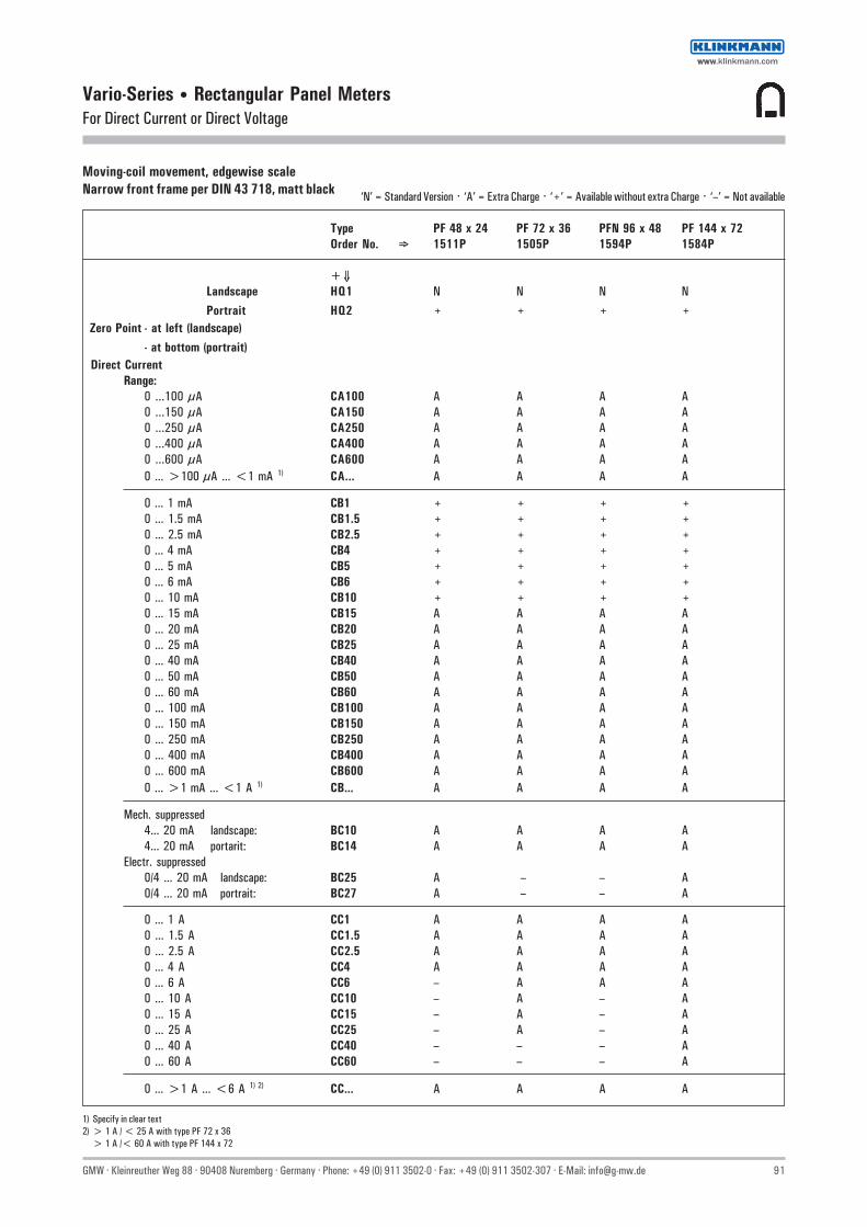
GMW · Kleinreuther Weg 88 · 90408 Nuremberg · Germany · Phone: +49 (0) 911 3502-0 · Fax: +49 (0) 911 3502-307 · E-Mail: [email protected] 91
Vario-Series • Rectangular Panel MetersFor Direct Current or Direct Voltage
Moving-coil movement, edgewise scaleNarrow front frame per DIN 43 718, matt black ‘N’ = Standard Version · ‘A’ = Extra Charge · ‘+’ = Available without extra Charge · ‘–’ = Not available
Type PF 48 x 24 PF 72 x 36 PFN 96 x 48 PF 144 x 72Order No. ⇒ 1511P 1505P 1594P 1584P
+⇓Landscape HQ1 N N N NPortrait HQ2 + + + +
Zero Point - at left (landscape)- at bottom (portrait)
Direct CurrentRange:
0 ...100 µA CA100 A A A A0 ...150 µA CA150 A A A A0 ...250 µA CA250 A A A A0 ...400 µA CA400 A A A A0 ...600 µA CA600 A A A A0 ... >100 µA ... <1 mA 1) CA... A A A A
0 ... 1 mA CB1 + + + +0 ... 1.5 mA CB1.5 + + + +0 ... 2.5 mA CB2.5 + + + +0 ... 4 mA CB4 + + + +0 ... 5 mA CB5 + + + +0 ... 6 mA CB6 + + + +0 ... 10 mA CB10 + + + +0 ... 15 mA CB15 A A A A0 ... 20 mA CB20 A A A A0 ... 25 mA CB25 A A A A0 ... 40 mA CB40 A A A A0 ... 50 mA CB50 A A A A0 ... 60 mA CB60 A A A A0 ... 100 mA CB100 A A A A0 ... 150 mA CB150 A A A A0 ... 250 mA CB250 A A A A0 ... 400 mA CB400 A A A A0 ... 600 mA CB600 A A A A0 ... >1 mA ... <1 A 1) CB... A A A A
Mech. suppressed4... 20 mA landscape: BC10 A A A A4... 20 mA portarit: BC14 A A A A
Electr. suppressed0/4 ... 20 mA landscape: BC25 A – – A0/4 ... 20 mA portrait: BC27 A – – A
0 ... 1 A CC1 A A A A0 ... 1.5 A CC1.5 A A A A0 ... 2.5 A CC2.5 A A A A0 ... 4 A CC4 A A A A0 ... 6 A CC6 – A A A0 ... 10 A CC10 – A – A0 ... 15 A CC15 – A – A0 ... 25 A CC25 – A – A0 ... 40 A CC40 – – – A0 ... 60 A CC60 – – – A
0 ... >1 A ... <6 A 1) 2) CC... A A A A
1) Specify in clear text2) > 1 A / < 25 A with type PF 72 x 36
> 1 A /< 60 A with type PF 144 x 72
wwwwww.klinkmann.com

92 GMW · Kleinreuther Weg 88 · 90408 Nuremberg · Germany · Phone: +49 (0) 911 3502-0 · Fax: +49 (0) 911 3502-307 · E-Mail: [email protected]
Vario-Series • Rectangular Panel MetersFor Direct Current or Direct Voltage
Moving-coil movement, edgewise scaleNarrow front frame per DIN 43 718, matt black
Type PF 48 x 24 PF 72 x 36 PFN 96 x 48 PF 144 x 72Order No. ⇒ 1511P 1505P 1594P 1584P
+⇓Landscape HQ1 N N N NPortrait HQ2 + + + +
Zero Point - at left (Landscape)- at bottom (Portrait)
Connection to Shunt (direct current)... A / 60 mV BE3 A A A A... A / 150 mV BE4 A A A A... A / ...>60 mV 1) BE981 A A A AScale: 1 A CG1 + + + +
1.5 A CG1.5 + + + +2.5 A CG2.5 + + + +4 A CG4 + + + +6 A CG6 + + + +10 A CG10 + + + +15 A CG15 + + + +25 A CG25 + + + +40 A CG40 + + + +60 A CG60 + + + +100 A CG100 + + + +150 A CG150 + + + +250 A CG250 + + + +400 A CG400 + + + +500 A CG500 + + + +600 A CG600 + + + +0 ...>1 A ...<1 kA 1) CG... + + + +1 kA CH1 + + + +1.5 kA CH1.5 + + + +2.5 kA CH2.5 + + + +4 kA CH4 + + + +6 kA CH6 + + + +10 kA CH10 + + + +>1 kA 1) 2) CH... + + + +
Direct VoltageRange: 0 ... 60 mV DB60 A A A A
0 ... 100 mV DB100 A A A A0 ... 150 mV DB150 A A A A0 ... 250 mV DB250 A A A A0 ... 400 mV DB400 A A A A0 ... 600 mV DB600 A A A A0 ...>60 mV...<1 V 1) DB... A — — A0 ...>100 mV...<600 mV 1) DB... — A A —0 ... 1 V DC1 A A A A0 ... 1.5 V DC1.5 A A A A0 ... 2.5 V DC2.5 A A A A0 ... 3 V DC3 A A A A0 ... 4 V DC4 A A A A0 ... 6 V DC6 A A A A0 ... 10 V DC10 A A A A0 ... 15 V DC15 A A A A0 ... 25 V DC25 A A A A0 ... 40 V DC40 A A A A0 ... 60 V DC60 A A A A0 ... 100 V DC100 A A A A0 ... 150 V DC150 — A A A0 ... 250 V DC250 — A A —0 ... 400 V DC400 — A A —0 ... 500 V DC500 — A A —0 ... 600 V DC600 — A A —0 ...>1 V ...<600 V 1) 2) DC... — A A —
1) Specify in clear text2) For higher voltages see voltage dividers
‘N’ = Standard Version · ‘A’ = Extra Charge · ‘+’ = Available without extra Charge · ‘–’ = Not available
wwwwww.klinkmann.com

GMW · Kleinreuther Weg 88 · 90408 Nuremberg · Germany · Phone: +49 (0) 911 3502-0 · Fax: +49 (0) 911 3502-307 · E-Mail: [email protected] 93
Vario-Series • Rectangular Panel MetersFor Direct Current or Direct Voltage
Moving-coil movement, edgewise scaleNarrow front frame per DIN 43 718, matt blackPlease note when ordering:Only one Identification No. with the same letter sequence may be chosen.Order No. with Identification No. N (standard model) can be left out.
‘N’ = Standard Version · ‘A’ = Extra Charge · ‘+’ = Available without extra Charge · ‘–’ = Not available
Type PF 48 x 24 PF 72 x 36 PFN 96 x 48 PF 144 x 72Order No. ⇒ 1511P 1505P 1594P 1584P
Identification+⇓
Landscape HQ1 N N N N Portrait HQ2 + + + +
GENERAL VARIANTSZero PointZero point at left (landscape) BC1 N N N NZero point at bottom (portrait) BC4 + + + +Zero point at center BC2 A A A AZero point as disired (specify in clear text) BC20 A A A AZero point at left (landscape), BC16 A A A A
mech. suppressed (not for 4-20 mA)Zero point at bottom (portrait), BC18 A A A A
mech. suppresses (not for 4-20 mA)(max. supression 20 %;
measuring range ≥ 250 µA / ≥ 250 mV.Ri 1 kΩ/V; specify in clear text)
Internal Resistance with VoltmetersStandard (see technical data) IR99 N N N NRi approx. 10 kΩ/V (measuring input ≥ 2 V; exception: IR10 A A A A
≥ 5 V / ≤ 150 V with 96 x 48 a. 72 x 36)Ri = 1 kΩ/V±1% at nominal temperature IR30 A – – A
(measuring input ≥ 1 V)Ri = 10 kΩ/V±1% at nominal temperature IR40 A – – A
(measuring input ≥ 2 V)
Potentiometer for Adjustment with VoltmetersVoltmeter without potentiometer for adjustment MP99 N N N NVoltmeter with potentiometer for adjustment MP1 – – A AAdjustment range ±15 %
(measuring input ≥ 6 V / ≤ 400 V; class 1.5 only; Ri1) according to list)
Lead Resistance when connected toShunts ...A/60 mV a. ...A/150 mVStandard version 0.06 Ω IG99 N N N NOther than 0.06 Ω (specify in clear text), IG999 A A A A
Limiting value: ...A/60 mV for class 1.5 max. 1 Ω...A/150 mV for class 1.5 max. 7 Ω
AccuracyClass 2.5 IE25 N – – –Class 1.5 (for sizes 48 x 24 / 24 x 48 available only IE15 A N N N
in combination with tube pointer)Class 1.0 (measuring input ≥ 40 µA / ≥ 60 mV) IE10 – – – A
Position of UseControl panel vertical LA1 N N N NControl panel horizontal LA2 + + + +Other LA999 A A A A(Please specify angle between scale and horizontal)
Special FeaturesNormal vibration and shock resistance LN99 N N N NSuitable for marine use with the following approvals:Germanischer Lloyd (class 1.5 only) LN2 – – – A 2)
Vibration resis. 2.5 g, shock resis. 30 g LN56 A 3) A A A1) Exception: The standard version (size 96 x 48) of the potentiometer for adjustment has a current consumption of approx. 100 µA2) 0 ... 1 mA, 0 ... 20 mA, 4 ... 20 mA, ≥ 1.5 V3) Available only in combination with slider
wwwwww.klinkmann.com

94 GMW · Kleinreuther Weg 88 · 90408 Nuremberg · Germany · Phone: +49 (0) 911 3502-0 · Fax: +49 (0) 911 3502-307 · E-Mail: [email protected]
Vario-Series • Rectangular Panel MetersFor Direct Current or Direct Voltage
Moving-coil movement, edgewise scaleNarrow front frame per DIN 43 718, matt black
Please note when ordering:Only one Identification No. with the same letter sequence may be chosen.Order No. with Identification No. N (standard model) can be left out.
‘N’ = Standard Version · ‘A’ = Extra Charge · ‘+’ = Available without extra Charge · ‘–’ = Not available
Type PF 48 x 24 PF 72 x 36 PFN 96 x 48 PF 144 x 72Order No. ⇒ 1511P 1505P 1594P 1584P
Identification+⇓
Landscape HQ1 N N N NPortrait HQ2 + + + +
SCALE VARIANTS
ScaleIn accordance with measuring input GF99 N N N NBlank scale (lower/upper value markings, GF28 + + + +
company logos, symbols)
Scale CharacteristicsCurrent / Voltage linear SD1 N N N NAccording to curve (not current / voltage linear) SD6 A A A A
Division and PointerSingle division GD1 N N N NDouble division GD2 A A A ACoarse-fine division SE1 – N N NFine division SE3 – – – ASpecial division SE5 N – – –Beam pointer with for single division RA1 – N – Nknife-edge for double division RA2 – – – +Beam pointer with for single division RA4 – N N –knife-edge and double divisionKnife-edge pointer for single division RA10 – – – A
for double division RA11 – – – ABar indicator for single division RA40 N – – –Tube pointer for single division RA30 A – – –Tube pointer for double division RA31 A – – –
Additional ImprintSecond numbering (specify in clear text) SK992 A A A AInscription:Without additional inscription SM99 N N N NInscription ≤ 15 characters German SM991 A A A A
>15 characters German SM992 A A A A≤ 15 characters other language SM993 A A A A>15 characters other language SM994 A A A A
(Other language in Latin lettering, specify in clear text)Coloured mark red RAL 2002 (specify in clear text) ST991 A A A AColoured sectors yellow RAL 1021, green RAL 6018or red RAL 2002 (specify in clear text) SU991 A A A A
wwwwww.klinkmann.com

GMW · Kleinreuther Weg 88 · 90408 Nuremberg · Germany · Phone: +49 (0) 911 3502-0 · Fax: +49 (0) 911 3502-307 · E-Mail: [email protected] 95
Vario-Series • Rectangular Panel MetersFor Direct Current or Direct Voltage
Moving-coil movement, edgewise scaleNarrow front frame per DIN 43 718, matt black
Please note when ordering:Only one Identification No. with the same letter sequence may be chosen.Order No. with Identification No. N (standard model) can be left out.
‘N’ = Standard Version · ‘A’ = Extra Charge · ‘+’ = Available without extra Charge · ‘–’ = Not available
Type PF 48 x 24 PF 72 x 36 PFN 96 x 48 PF 144 x 72Order No. ⇒ 1511P 1505P 1594P 1584P
Identification+⇓
landscape HQ1 N N N Nportrait HQ2 + + + +
SCALE VARIANTS
Scale / Pointer ColoursScale white; imprint and pointer black SG99 N N N NScale balck; imprint and pointer white SG1 A 1) A 1) A 1) A 1)
Scale black; imprint and pointer yellow SG2 A 1) A 1) A 1) A 1)
Scale black; imprint white, pointer yellow SG3 A 1) A 1) A 1) A 1)
Dial Illumination
Without Dial Illumination PA99 N N N NWith direct dial illumination PA1 – A A A(Plexiglass scale, scale and dial illumination white)Note:Completion with Voltage Order No. PB... necessary.
Light conductor with mask, dial illumination white PA6 – – – A 2)
Light conductor with mask, dial illumination red PA7 – – – A 2)
Note:Completion with Voltage Order No. PB... and SG necessary.(SG 99 as light conductor with mask not available)
Voltage for Dial Illumination24 V PB5 – + + +28 V PB6 – + + +
1) Additional one-off costs for special scale printing on request2) Prices on request
wwwwww.klinkmann.com

96 GMW · Kleinreuther Weg 88 · 90408 Nuremberg · Germany · Phone: +49 (0) 911 3502-0 · Fax: +49 (0) 911 3502-307 · E-Mail: [email protected]
Vario-Series • Rectangular Panel MetersFor Direct Current or Direct Voltage
Moving-coil movement, edgewise scaleNarrow front frame per DIN 43 718, matt black
Please note when ordering:Only one Identification No. with the same letter sequence may be chosen.Order No. with Identification No. N (standard model) can be left out.
‘N’ = Standard Version · ‘A’ = Extra Charge · ‘+’ = Available without extra Charge · ‘–’ = Not available
Type PF 48 x 24 PF 72 x 36 PFN 96 x 48 PF 144 x 72Order No. ⇒ 1511P 1505P 1594P 1584P
Identification+⇓
Landscape HQ1 N N N NPortrait HQ2 + + + +
HOUSING VARIANTSApplicationStandard version LB99 N N N Nconditionally tropic resistant LB1 A A A A
ProtectionAccording to list LH99 N N N NFront housing-panel protection IP54, clamps IP00 LH21 A – – AFront housing-panel protection IP54, clamps IP20 LH22 – A A –Earthquake-proof (possible combination: LH99 or LH21) LH10 A A A A
Front Frame ColourMatt black MA2 N N N NMatt grey RAL 7037 MA11 A A A AMatt stone grey RAL 7032 MA12 A A A AMatt dark beige approx. RAL 1019 MA21 A A A AMatt light grey RAL 7035 MA14 A – A A
Intermediate Frame, Height 3 mmWithout intermediate frame MC99 N N N NIntermediate frame shiny black MC1 A – – –Intermediate frame shiny grey RAL 7037 MC2 A – – –Intermediate frame with size 48 x24 available only in combinationwith shortened expanding spring (MN 24)
Glass WindowStandard version MG99 N N N NAnti-glare glass MG1 A A A A
FastenersExpanding spring MN20 N – – –Shortened expanding spring (necessary when version MN24 + – – –
with intermediate frame)Catch spring MN21 + – – –Subklew (stiled slider) MN32 + – – –Slider MN50 + – – –Angled slider for APE-Grid MN51 + – – –Fastener B DIN 43 835 MN11 – – – –Screw spindle MN22 – N N –Fastener C MN12 – – – N
IdentificationWithout identification MZ99 N N N NIdentification on the back (specify in clear text) MZ998 A A A A
Inscription StripesWithout inscription stripes SS99 N N N NInscription on front face on top (specify in clear text) SS991 A 1) – A 1) A 1)
Inscription on front face at bottom (specify in clear text) SS992 A 1) A 1) A 1) A 2)
Contact ProtectionWithout terminal cover VB99 N N N NOverall terminal cover VB2 A – – –Single terminal cover (Voltmeter and Ammeter ≤ 4 A) VB1 + + + +
1) For landscape only2) For protarit only
wwwwww.klinkmann.com
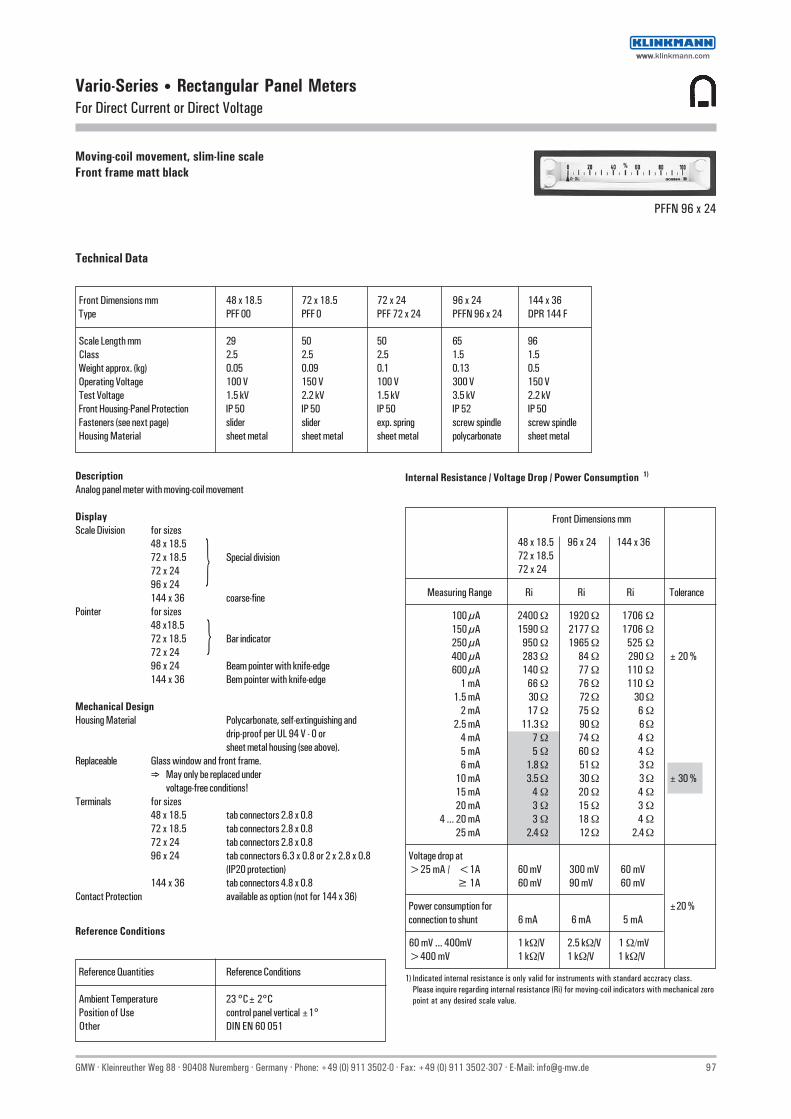
GMW · Kleinreuther Weg 88 · 90408 Nuremberg · Germany · Phone: +49 (0) 911 3502-0 · Fax: +49 (0) 911 3502-307 · E-Mail: [email protected] 97
Vario-Series • Rectangular Panel MetersFor Direct Current or Direct Voltage
Moving-coil movement, slim-line scaleFront frame matt black
PFFN 96 x 24
Technical Data
Front Dimensions mm 48 x 18.5 72 x 18.5 72 x 24 96 x 24 144 x 36 Type PFF 00 PFF 0 PFF 72 x 24 PFFN 96 x 24 DPR 144 F
Scale Length mm 29 50 50 65 96 Class 2.5 2.5 2.5 1.5 1.5 Weight approx. (kg) 0.05 0.09 0.1 0.13 0.5 Operating Voltage 100 V 150 V 100 V 300 V 150 V Test Voltage 1.5 kV 2.2 kV 1.5 kV 3.5 kV 2.2 kV Front Housing-Panel Protection IP 50 IP 50 IP 50 IP 52 IP 50 Fasteners (see next page) slider slider exp. spring screw spindle screw spindle Housing Material sheet metal sheet metal sheet metal polycarbonate sheet metal
DescriptionAnalog panel meter with moving-coil movement
DisplayScale Division for sizes
48 x 18.572 x 18.5 Special division72 x 2496 x 24144 x 36 coarse-fine
Pointer for sizes48 x18.572 x 18.5 Bar indicator72 x 2496 x 24 Beam pointer with knife-edge144 x 36 Bem pointer with knife-edge
Mechanical DesignHousing Material Polycarbonate, self-extinguishing and
drip-proof per UL 94 V - 0 orsheet metal housing (see above).
Replaceable Glass window and front frame.⇒ May only be replaced under
voltage-free conditions!Terminals for sizes
48 x 18.5 tab connectors 2.8 x 0.872 x 18.5 tab connectors 2.8 x 0.872 x 24 tab connectors 2.8 x 0.896 x 24 tab connectors 6.3 x 0.8 or 2 x 2.8 x 0.8
(IP20 protection)144 x 36 tab connectors 4.8 x 0.8
Contact Protection available as option (not for 144 x 36)
Reference Conditions
Reference Quantities Reference Conditions
Ambient Temperature 23 °C± 2°C Position of Use control panel vertical ±1° Other DIN EN 60 051
1) Indicated internal resistance is only valid for instruments with standard acczracy class.Please inquire regarding internal resistance (Ri) for moving-coil indicators with mechanical zeropoint at any desired scale value.
Internal Resistance / Voltage Drop / Power Consumption 1)
Front Dimensions mm
48 x 18.5 96 x 24 144 x 3672 x 18.572 x 24
Measuring Range Ri Ri Ri Tolerance
100 µA 2400 Ω 1920 Ω 1706 Ω150 µA 1590 Ω 2177 Ω 1706 Ω250 µA 950 Ω 1965 Ω 525 Ω400 µA 283 Ω 84 Ω 290 Ω ± 20 %600 µA 140 Ω 77 Ω 110 Ω
1 mA 66 Ω 76 Ω 110 Ω1.5 mA 30 Ω 72 Ω 30 Ω
2 mA 17 Ω 75 Ω 6 Ω2.5 mA 11.3 Ω 90 Ω 6 Ω
4 mA 7 Ω 74 Ω 4 Ω5 mA 5 Ω 60 Ω 4 Ω6 mA 1.8 Ω 51 Ω 3 Ω
10 mA 3.5 Ω 30 Ω 3 Ω ± 30 %15 mA 4 Ω 20 Ω 4 Ω20 mA 3 Ω 15 Ω 3 Ω
4 ... 20 mA 3 Ω 18 Ω 4 Ω25 mA 2.4 Ω 12 Ω 2.4 Ω
Voltage drop at >25 mA / <1A 60 mV 300 mV 60 mV
≥ 1A 60 mV 90 mV 60 mV
Power consumption for ±20 % connection to shunt 6 mA 6 mA 5 mA
60 mV ... 400mV 1 kΩ/V 2.5 kΩ/V 1 Ω/mV >400 mV 1 kΩ/V 1 kΩ/V 1 kΩ/V
wwwwww.klinkmann.com

98 GMW · Kleinreuther Weg 88 · 90408 Nuremberg · Germany · Phone: +49 (0) 911 3502-0 · Fax: +49 (0) 911 3502-307 · E-Mail: [email protected]
Vario-Series • Rectangular Panel MetersFor Direct Current or Direct Voltage
Expanding Springs
Control panel thickness ≥1 mmSize 72 x 24 for mounting in DIN-Grid,Siemens-Grid M 25 and Kreutzenbeck-Grid
Catch Spring I
As option for size 72 x 24 for Mauell-Grid,H & B Unibloc-Grid and Hein-Grid
Slider
Control panel thickness 1 to 5 mmFor sizes 48 x 18.5 and 72 x 18.5 for mounting in DIN-Grid,Also available as option for size 72 x 24.
Basic Dimensions
Fastener C DIN 43 835
Control panel thickness 1 to 40 mmScrew clamp M5, longer version, for size 144 x 36 for mounting inDIN-Grid.
Screw Spindle
Control panel thickness up to 40 mmScrew spindle for size 96 x 24 for mounting inDIN-Grid and all remaining grids.
Clamping Springs
Control panel thickness ≥ 1 mmAvailable as option for size 96 x 24, retractable from front face,for mounting in DIN-Grid
Drawing to Scale (on request)1303A1839H0 for size 96 x 24
Drawing to Scales (on request)0101A226 for sizes 48 x 18.5 and 72 x 18.50101A247 for size 72 x 2495.207-95 for size 144 x 36
Ordering ExampleSize 96 x 24 mm0 ... 40 V Direct Voltage
Techn. Data Order No. Type: PFFN 96 x 24 1524P, DC40
Front in mm Nominal Dimensions Cutout Dimensions Inst. Depth Terminals Contact Protection at Terminalsa1 x a2 h l1 x l2 t e f= Full Contact Protection
48 x 18.5 48 x 18.5 5 44.8+0.15 x 17.3+0.15 56 12 — 72 x 18.5 72 x 18.5 5 69.3+0.15 x 17.3+0.15 82 12 — 72 x 24 72 x 24 5 68+0.7 x 22+0.3 90 11 31 96 x 24 96 x 24 5 92+0.8 x 22+0.3 126 0 — 144 x 36 144 x 36 8 138+1 x 32.7+0.6 202 5 —
wwwwww.klinkmann.com

GMW · Kleinreuther Weg 88 · 90408 Nuremberg · Germany · Phone: +49 (0) 911 3502-0 · Fax: +49 (0) 911 3502-307 · E-Mail: [email protected] 99
‘N’ = Standard Version · ‘A’ = Extra Charge · ‘+’ = Available without extra Charge · ‘–’ = Not available
Vario-Series • Rectangular Panel MetersFor Direct Current or Direct Voltage
Moving-coil movement, slim-line scaleFront frame matt black
Front Dim. mm 48 x 18.5 72 x 18.5 72 x 24 96 x 24 144 x 36Type PFF 00 PFF 0 PFF 72 x 24 PFFN 96 x 24 DPR 144 FOrder No. ⇒ 1194P 1196P 1515P 1524P 21102...
+⇓ +⇓Landscape HQ1 N N N N NPortrait HQ2 + + + + +
Zero Point - at left (landscape)- at bottom (portrait)
Direct CurrentRange:0 ...100 µA CA100 A A A A ...342400 ...150 µA CA150 A A A A ...342700 ...250 µA CA250 A A A A ...343000 ...400 µA CA400 A A A A ...343200 ...600 µA CA600 A A A A ...34350
0 ...>100 µA ...<1 mA 1) CA... A A A A ...31005
0 ...1 mA CB1 + + + + ...351100 ...1.5 mA CB1.5 + + + + ...351200 ...2.5 mA CB2.5 + + + + ...351300 ...4 mA CB4 + + + + ...351400 ...5 mA CB5 + + + + ...351500 ...6 mA CB6 + + + + ...351600 ...10 mA CB10 + + + + ...351700 ...15 mA CB15 A A A A ...351800 ...20 mA CB20 A A A A ...351900 ...25 mA CB25 A A A A ...352000 ...40 mA CB40 A A A A ...352100 ...50 mA CB50 A A A A ...352200 ...60 mA CB60 A A A A ...352300 ... 100 mA CB100 A A A A ...352400 ... 150 mA CB150 A A A A ...352700 ... 250 mA CB250 A A A A ...353000 ... 400 mA CB400 A A A A ...353200 ... 600 mA CB600 A A A A ...35350
0 ...>1 mA ...<1 A 1) CB... A A A A ...31005
Mech. suppressed4...20 mA landscape : BC10 A A A A ...351954...20 mA portrait : BC14 A A A A ...35196
Electr. suppressed0/4...20 mA landscape : BC25 A A A – ...351990/4...20 mA portrait : BC27 A A A – ...35198
0 ...1 A CC1 A A A A ...361100 ...1.5 A CC1.5 A A A A ...361200 ...2.5 A CC2.5 A A A A ...361300 ...4 A CC4 A A A A ...36140
0 ...>1 A ...<4 A 1) CC... A A A A ...31005
1) Specify in clear text
wwwwww.klinkmann.com

100 GMW · Kleinreuther Weg 88 · 90408 Nuremberg · Germany · Phone: +49 (0) 911 3502-0 · Fax: +49 (0) 911 3502-307 · E-Mail: [email protected]
‘N’ = Standard Version · ‘A’ = Extra Charge · ‘+’ = Available without extra Charge · ‘–’ = Not available
Vario-Series • Rectangular Panel MetersFor Direct Current or Direct Voltage
Moving-coil movement, slim-line scaleFront frame matt black
Front Dim. mm 48 x 18.5 72 x 18.5 72 x 24 96 x 24 144 x 36Type PFF 00 PFF 0 PFF 72 x 24 PFFN 96 x 24 DPR 144 FOrder No. ⇒ 1194P 1196P 1515P 1524P 21102...
+⇓ +⇓Landscape HQ1 N N N N NPortrait HQ2 + + + + +
Zero Point - at left (landscape)- at bottom (portrait)
Connection to Shunt (direct current)... A / 60 mV BE3 A A A A ...32230... A / 150 mV BE4 A A A A ...32270... A / ...>60 mV 1) BE981 A A A A ...31005
Scale: 1 A CG1 + + + + +1.5 A CG1.5 + + + + +2.5 A CG2.5 + + + + +4 A CG4 + + + + +6 A CG6 + + + + +10 A CG10 + + + + +15 A CG15 + + + + +25 A CG25 + + + + +40 A CG40 + + + + +60 A CG60 + + + + +100 A CG100 + + + + +150 A CG150 + + + + +250 A CG250 + + + + +400 A CG400 + + + + +500 A CG500 + + + + +600 A CG600 + + + + +
0 ...>1 A ...<1 kA 1) CG... + + + + +1 kA CH1 + + + + +1.5 kA CH1.5 + + + + +2.5 kA CH2.5 + + + + +4 kA CH4 + + + + +6 kA CH6 + + + + +10 kA CH10 + + + + +
>1 kA 1) CH... + + + + +
Direct VoltageRange: 0 ... 60 mV DB60 A A A A ...31230
0 ... 100 mV DB100 A A A A ...312400 ... 150 mV DB150 A A A A ...312700 ... 250 mV DB250 A A A A ...313000 ... 400 mV DB400 A A A A ...313200 ... 600 mV DB600 A A A A ...31350
0 ...>60 mV...<1 V 1) DB... A A A — ...310050 ...>100 mV...<600 mV 1) DB... — — — A ...31005
0 ...1 V DC1 A A A A ...331100 ...1.5 V DC1.5 A A A A ...331200 ...2.5 V DC2.5 A A A A ...331300 ...3 V DC3 A A A A ...331350 ...4 V DC4 A A A A ...331400 ...6 V DC6 A A A A ...331600 ...10 V DC10 A A A A ...331700 ...15 V DC15 A A A A ...331800 ...25 V DC25 A A A A ...332000 ...40 V DC40 A A A A ...332100 ...60 V DC60 A A A A ...332300 ... 100 V DC100 A A A A ...332400 ... 150 V DC150 — A — A ...332700 ... 250 V DC250 — — — A —0 ... 400 V DC400 — — — A —0 ... 500 V DC500 — — — A —0 ... 600 V DC600 — — — A —
0 ...>1 V ...<600 V 1) 2) DC... — — — A —
1) Specify in clear text2) For higher voltages see voltage dividers
wwwwww.klinkmann.com

GMW · Kleinreuther Weg 88 · 90408 Nuremberg · Germany · Phone: +49 (0) 911 3502-0 · Fax: +49 (0) 911 3502-307 · E-Mail: [email protected] 101
Vario-Series • Rectangular Panel MetersFor Direct Current or Direct Voltage
Moving-coil movement, slim-line scaleFront frame matt black
Front Dim. mm 48 x 18.5 72 x 18.5 72 x 24 96 x 24 144 x 36Type PFF 00 PFF 0 PFF 72 x 24 PFFN 96 x 24 DPR 144 FOrder No. ⇒ 1194P 1196P 1515P 1524P 21102...
+⇓Landscape HQ1 N N N N NPortrait HQ2 + + + + +
GENERAL VARIANTS
Zero pint at left (landscape) BC1 N N N N NZero point at bottom (portrait) BC4 N N N N NZero point at center BC2 A A A A AZero point as desired (specify in clear text) BC20 A A A A AZero point at the left (landscape), BC16 A A A A Amech. suppressed (not 4-20 mA)Zero point at bottom (portrait), BC18 A A A A A
(Max. supression 20 %; measuring range ≥ 250 µA /≥ 250 mV, Ri 1 kΩ/V; specify in clear text)
Internal Resistance for VoltmetersStandard (see technical data) IR99 N N N N NRi approx. 10 kΩ/V (measuring input ≥ 2 V; IR10 A A A A AException: ≥ 5 V / ≤ 150 V size 96 x 24)Ri = 1 kΩ/V±1% at nominal temperature IR30 A A A – A(measuring input ≥ 1 V)Ri = 10 kΩ/V±1% at nominal temperature IR40 A A A – A(measuring input ≥ 2 V)
Potentiometer for Adjustment with VoltmetersVoltmeters without potentiometer for adjustment MP99 N N N N NVoltmeters with potentiometer for adjustment MP1 – – – A –Adjusment range ±15 % (measuring input ≥ 6 V / ≤ 400 V;Class 1.5 only; Ri according to list 1))
Lead Resistor when connecting toShunt resistors ...A/60 mV and ...A/150 mVStandard version 0.06 Ω IG99 N N N N NDiffering from 0.06 Ω (specify in clear text). IG999 A A A A ALimiting values: ...A / 60 mV for class 1.5 max. 1 Ω...A / 150 mV for class 1.5 max. 7 Ω
AccuracyClass 2.5 IE25 N N N – –Class 1.5 IE15 A 2) A 2) A 2) N 3) NClass 1.0 (measuring input ≥100 µA / ≥60 mV) IE10 – – – – A
Position of UseControl panel vertical LA1 N N N N NControl panel horizontal LA2 + + + + +Other LA999 A A A A A(Please specify angle between scale and horizontal)
Special FeaturesNormal vibration and shock resistance LN99 N N N N NVibration resis. 2.5 g, shock resis. 30 g LN56 A A A 4) A –
Please note when ordering:Only one Identification No. with the same letter sequence may be chosen.Order No. with Identification No. N (standard model) can be left out.
‘N’ = Standard Version · ‘A’ = Extra Charge · ‘+’ = Available without extra Charge · ‘–’ = Not available
1) Exception: The standard version (size 96 x 48) of the potentiometer for adjustment has a current consumption of approx. 100 µA2) Available only in combination with tube pointer3) Standard version without extra charge4) Available only in combination with slider
wwwwww.klinkmann.com

102 GMW · Kleinreuther Weg 88 · 90408 Nuremberg · Germany · Phone: +49 (0) 911 3502-0 · Fax: +49 (0) 911 3502-307 · E-Mail: [email protected]
Vario-Series • Rectangular Panel MetersFor Direct Current or Direct Voltage
Moving-coil movement, slim-line scaleFront frame matt black
Please note when ordering:Only one Identification No. with the same letter sequence may be chosen.Order No. with Identification No. N (standard model) can be left out.
‘N’ = Standard Version · ‘A’ = Extra Charge · ‘+’ = Available without extra Charge · ‘–’ = Not available
Front Dim. mm 48 x 18.5 72 x 18.5 72 x 24 96 x 24 144 x 36Type PFF 00 PFF 0 PFF 72 x 24 PFFN 96 x 24 DPR 144 FOrder No. ⇒ 1194P 1196P 1515P 1524P 21102...
+⇓Landscape HQ1 N N N N NPortrait HQ2 + + + + +
SCALE VARIANTS
ScaleIn accordance with measuring input GF99 N N N N NBlank scale (lower/upper value markings, GF28 + + + + +
company logos, symbols)Scale CharacteristicsCurrent / Voltage proportional SD1 N N N N NAccording to curve (not current / voltage proportional) SD6 A A A A A
Division and PointerSingle division GD1 N N N N NDouble division GD2 A A A A ASpecial division SE5 N N N N ACoarse-fine division SE1 – – – – NBar indicator for single division RA40 N N N – –Tube pointer for double division RA31 A A A – –Beam pointer with knife-edge
for single and double division RA4 – – – N –
Knife-edge pointer for single division RA10 – – – – Nfor double division RA11 – – – – A
Additional ImprintSecond numbering (specify in clear text) SK992 A A A A AInscription:Without additional inscription SM99 N N N N NInscription ≤ 15 characters German SM991 A A A A A
>15 characters German SM992 A A A A A≤15 characters other language SM993 A A A A A>15 characters other language SM994 A A A A A
(Other language in Latin lettering, specify in clear text)
Coloured mark red RAL 2002 ST991 A A A A A(specify in clear text)Coloured sector yell. RAL 1021, green RAL 6018 SU991 A A A A Aor red RAL 2002 (specify in clear text)
wwwwww.klinkmann.com

GMW · Kleinreuther Weg 88 · 90408 Nuremberg · Germany · Phone: +49 (0) 911 3502-0 · Fax: +49 (0) 911 3502-307 · E-Mail: [email protected] 103
Vario-Series • Rectangular Panel MetersFor Direct Current or Direct Voltage
Moving-coil movement, slim-line scaleFront frame matt black
Please note when ordering:Only one Identification No. with the same letter sequence may be chosen.Order No. with Identification No. N (standard model) can be left out.
‘N’ = Standard Version · ‘A’ = Extra Charge · ‘+’ = Available without extra Charge · ‘–’ = Not available
Front Dim. mm 48 x 18.5 72 x 18.5 72 x 24 96 x 24 144 x 36Type PFF 00 PFF 0 PFF 72 x 24 PFFN 96 x 24 DPR 144 FOrder No. ⇒ 1194P 1196P 1515P 1524P 21102...
+⇓Landscape HQ1 N N N N NPortrait HQ2 + + + + +
SCALE VARIANTS
Scale / Pointer ColoursScale white; imprint and pointer black SG99 N N N N NScale black; imprint and pointer white SG1 – – A 1) A 1) A 1)
Scale black; imprint and pointer yellow SG2 – – A 1) A 1) A 1)
Scale black; imprint white, pointer yellow SG3 – – A 1) A 1) A 1)
Dial IlluminationWithout dial illumination PA99 N N N N NWith direct dial illumination PA1 A A A A –(Plexiglass scale, scale and dial illumination white)Note: Completion with Voltage Order No. PB... necessary.
Voltage for Dial Illumination24 V PB5 – – – + –28 V PB6 – – – + –24 V (2 x 12 V-lamps connected in series) PB7 + + + – –28 V (2 x 14 V-lamps connected in series) PB8 + + + – –
1) Additional one-off costs for special scale printing on request
wwwwww.klinkmann.com

104 GMW · Kleinreuther Weg 88 · 90408 Nuremberg · Germany · Phone: +49 (0) 911 3502-0 · Fax: +49 (0) 911 3502-307 · E-Mail: [email protected]
Vario-Series • Rectangular Panel MetersFor Direct Current or Direct Voltage
Moving-coil movement, slim-line scaleFront frame matt blackPlease note when ordering:Only one Identification No. with the same letter sequence may be chosen.Order No. with Identification No. N (standard model) can be left out.
‘N’ = Standard Version · ‘A’ = Extra Charge · ‘+’ = Available without extra Charge · ‘–’ = Not available
Front Dim. mm 48 x 18.5 72 x 18.5 72 x 24 96 x 24 144 x 36Type PFF 00 PFF 0 PFF 72 x 24 PFFN 96 x 24 DPR 144 FOrder No. ⇒ 1194P 1196P 1515P 1524P 21102...
+⇓Landscape HQ1 N N N N NPortrait HQ2 + + + + +
HOUSING VARIANTS
ApplicationStandard version LB99 N N N N NTropic resistant LB1 A A A A A
ProtectionStandard (see technical data) LH99 N N N N NFront housing-panel protection IP54, con. IP00 LH21 – – A – AFront housing-panel protection IP54, con. IP20 LH22 – – – A –Earthquake-proof (possible combination: LH99
or LH21) LH10 – – – A –
Front Frame ColourMatt black MA2 N N N N NMatt grey RAL 7037 MA11 A A A A AMatt stone grey RAL 7032 MA12 – – A A –Matt light grey RAL 7035 MA14 – – A A –Matt dark beige approx. RAL 1019 MA21 – – A A –
Glass WindowStandard version MG99 N N N N NAnti-glare glass MG1 A A A A A
MountingSlider MN50 N N A – –Expanding spring MN20 – – N – –Catch spring MN21 – – + – –Screw spindle MN22 – – – N NClamping Spring MN23 – – – + –Fastener C MN12 – – – – –Subklew (stiled slider) MN32 – – A – –Angled slider for APE-Grid MN51 – – A – –
IdentificationWithout identification MZ99 N N N N NIdentification on the back (specify in clear text) MZ998 A A A A A
Label StripWithout label strip SS99 N N N N NLabel on front face on top (spec. in clear text) SS991 – – A 1) A 1) –Label on front face at bottom SS992 – – A 1) A 1) –
(specify in clear text)
Contact ProtectionWithout terminal cover VB99 N N N N NOverall terminal cover VB2 – – A – –Single terminal cover VB1 + + + + –
1) Available only for landscape format
wwwwww.klinkmann.com

GMW · Kleinreuther Weg 88 · 90408 Nuremberg · Germany · Phone: +49 (0) 911 3502-0 · Fax: +49 (0) 911 3502-307 · E-Mail: [email protected] 105
Vario-Series • Rectangular Indicator/ControllersFor Direct Current or Direct Voltage with 1 or 2 Limit Contacts
Moving-coil movement, edgewise scaleNarrow front frame per DIN 43 718, matt black
PFFN 96 x 24 MTechnical Data
Front Dimensions mm 96 x 24 96 x 48 144 x 36 144 x 72Type PFFN 96 x 24 M PFN 96 x 48 M KODPR 144 F KODPR 144 SE
Scale Length mm 65 65 96 98Class 1.5 1.5 1.5 1.5Weight approx. (kg) 0.2 0.5 (at UH AC) 0.6 1.1
0.2 (at UH DC)Sampling electronic electronic electronic electronicRelative Switching Speed 1 % 1 % 1 % 1 %
(max. error as related to scale length)Repetition Accuracy 0.1 % 0.1 % 0.1 % 0.1 %
(at nom. aux. voltage and 23 °C)Number of Limits 1 or 2 1 or 2 1 or 2 1 or 2Min. Limit Separation 3 % 3 % 1.5 % 1.5 %
(of scale length)Output Relay built in built in attachable on back attachable on backOutput Contact 1 changeover per limit 1 changeover per limit 1 changeover per limit 1 changeover per limitSwitching Capacity with Restive Load
Max. Switching Voltage 250 V AC / 250 V DC 250 V AC / 250 V DC 250 V AC / 250 V DC 250 V AC / 250 V DCMax. Switching Current 6 A AC / 6 A DC 6 A AC / 6 A DC 3 A AC / 3 A DC 3 A AC / 3 A DCNominal Switching Capacity 500 VA / 50 W 500 VA / 50 W 750 VA / 50 W 750 VA / 50 W
Service Life at nominal Switching Capacity >106 switching cycles >106 switching cycles >106 switching cycles >106 switching cyclesMax. Switching Time 500 ms 500 ms 50 ms 50 msAuxiliary Voltage (UH) 24 V DC (20...24...30 V) 1) 24 V DC (20...24...30 V) o. 24 V DC (20...24...30 V) 1) 24 V DC (20...24...30 V) 1)
24 ... 240 V AC. 45...65 HzPower Consumption 4 VA / 4.5 W 4 VA / 4.5 W 5 VA / 4 W 5 VA / 4 WSafety Class CAT III CAT III CAT III CAT IIIPollution Degree 2 2 2 2Operating Voltage 300 V 300 V 150 V 150 VOperating Voltage for Measuring Ranges
>250 V ... ≤ 600 V 300 V 600 V 150 V 150 VTest Voltage 3.5 kV 5.8 kV 2.2 kV 2.2 kVFront Housing-Panel Protection IP 52 IP 52 IP 50 IP 50Fasteners screw spindle screw spindle screw spindle screw spindle
DescriptionAnalog indicator/controller with moving-coil movement for direct current or directvoltage
DisplayScale Division Special DivisionPointer Beam pointer with knife-edge for single and double Division
Mechanical DesignHousing Material Polycarbonate, self-extinguishing and drip-proof per UL 94 V-OReplaceable Glass windows and front frames
⇒ May only be replaced undervoltage-free conditions!
Terminals Tab connectors (IP20 protection) 1 x 6.3 x 0.8 mm, 2 x 2.8 x 0.8 mm or 4.8 x 0.8 mm
Reference Conditions
Reference Quantities Reference Conditions
Ambient Temperature 23 °C ±2°CPosition of Use control panel vertical ±1°Other DIN EN 60 051
1) With separate power supply for following voltages: 24 V AC, 115 V AC and 230 V AC, ±10 %; see accessories, page 130
Internal Resistance / Voltage Drop / Power Consumption(Values only apply with zero point at let or at bottom)
Measuring Range Internal Resistance / Voltage Drop /Power Consumption
≥ 100 µA / ≤ 10 mA ≤ 100 mV> 10 mA / ≤ 6 A ≤ 100 mV≥ 60 mV / ≤ 1 V ≥ 200 kΩ/V> 1 V / ≤ 50 V ≥ 10 kΩ/V> 50 V / ≤ 600 V ≥ 10 kΩ/V0/4 ... 20 mA 6 Ω 1)
Connection to Shunt 6 mA 2)
1) Tolerance ±30% 2) Tolerance ±20%
wwwwww.klinkmann.com

106 GMW · Kleinreuther Weg 88 · 90408 Nuremberg · Germany · Phone: +49 (0) 911 3502-0 · Fax: +49 (0) 911 3502-307 · E-Mail: [email protected]
Vario-Series • Rectangular Indicator/ControllersFor Direct Current or Direct Voltage with 1 or 2 Limit Contacts
General IssuesIndicator/controllers are meters with adjustable limits.The accuracy of the limits are not influenced by the contacts.Our meters and indicator/controllers comply with the regulations of the EuropeanGuidelines 73/23/EWG. This is proven by the compliance with the following standards:IEC 61010-1/A2 / EN 61010-1/A2 VDE 0411-1/A1 (Safety Regulations)IEC 60051/EN 60051/DIN EN 60051 (Meters with Scale Display)EN 50081-2: 1993 EMV (Emitted Interfernce, Industries)EN 50082-2: 1995 EMV (Emitted Interfernce, Industries)To protect the movable part of the indicator/controller against shocks, the bearings arespring mounted.
ApplicationIndicator/controllers display the actual value and energise with the help of one or morelimits one or more relays. Their contacts can be used for monitoring, operating orcontrolling.Indicator/controllers are also available with logic output (transistor output).
SamplingThe sampling of the indicator/controllers works contact-free.When the pointer reaches the limit the switching operation will be disengaged.
ContactingThe max. contact disengages the switching operation when it overshoots the adjustedscale value. The min. contact disengages the switching operation when it undershootsthe adjusted scale value.
FastenersScrew spindle(control panel thickness 1 ... 40 mm)
All indicator/controllers cause a permanent contact. This means that the output signalis held up as long as the pointer does not overrun the adjusted limit. The indicator/controllers are availabe as closed-circuit current model or working current model (seedifferent Order No.).
Closed-Circuit Current Model: When the indicator/controller is not-operated, avoltage is impressed on the relays (output signal H, logic output). The voltage drops assoon as one of the contact marks is undershot or overshot. The same happens when apower breakdown or an electronic breakdown occurs and no limit is overshot orundershot (self supervision). A short-term power failure leads to the same effect.
Working Current Model: When the indicator/controller is not-operated the relaysare in zero current condition (output signal L, logic output). As soon as one of the limitsis overshot or undershot the relays pick up (output signal H).
Position of Limits
Basic Dimensions Relay
Ordering Example:Indicator/Controller 96 x 24 mm for direct voltage, landscape scale,Measuring range 0 ... 100 V, direct connection, zero point at left,Working voltage-version with 2 limit contacts (Max. - Max.)
Techn. Data Order No. Type: PFFN 96 x 24 M 2524P, AM11, DC100
Front Dim. mm Nominal Dimensions Cutout Dimensions Installation Depth (t) Installation Depth (t)a1 x a2 h l1 x l2 Relay Output Logic Output
96 x 24 96 x 24 5 92+0.8 x 22.2+0.3 146 12696 x 48 96 x 48 5 92+0.8 x 45+0.6 146 126144 x 36 144 x 36 8 137.5+0.8 x 32.5+0.6 246 202144 x 72 144 x 72 8 137.7+0.8 x 67.7+0.6 248 205
Contact Assignments
Measured Quantity
Auxiliary Voltage
Limit Contact 2
Limit Contact 1
Relay Output Logic Output
The output contacts are shownin the wiring diagram in the zerocurrent condition
+ terminals are electricallyconnected within the instrument
wwwwww.klinkmann.com

GMW · Kleinreuther Weg 88 · 90408 Nuremberg · Germany · Phone: +49 (0) 911 3502-0 · Fax: +49 (0) 911 3502-307 · E-Mail: [email protected] 107
Vario-Series • Rectangular Indicator/ControllersFor Direct Current or Direct Voltage with 1 or 2 Limit Contacts
Moving-coil movement, edgewise scaleNarrow front frame per DIN 43 718, matt black
‘N’ = Standard Version · ‘A’ = Extra Charge · ‘+’ = Available without extra Charge · ‘–’ = Not available
Type PFFN 96x24 M PFN 96x48 M KODPR 144 F KODPR 144 SEOrder No. ⇒ 2524P 2594P 61102... 65102...
+⇓ +⇓ +⇓Landscape HQ1 N N N NPortrait HQ2 + + + +
Limits
Closed-Circuit Max. AM3 + + + +Current Model Min. AM4 + + + +
Min. - Max. AM5 A A A AMax. - Max. AM6 A A A AMin. - Min. AM7 A A A A
Working Current Max. AM8 + + + +Model Min. AM9 + + + +
Min. - Max. AM10 A A A AMax. - Max. AM11 A A A AMin. - Min. AM12 A A A A
Zero Point - left / bottomDirect Current
Range 0 ... 100 µA CA100 A A ...34240 ...342400 ... 150 µA CA150 A A ...34270 ...342700 ... 250 µA CA250 A + ...34300 ...343000 ... 400 µA CA400 A + ...34320 ...343200 ... 600 µA CA600 — + ...34350 ...34350
> 100 µA ...< 1 mA 1) CA... A A ...31005 ...31005
0 ...1 mA CB1 + + ...35110 ...351100 ...1.5 mA CB1.5 + + ...35120 ...351200 ... 2.5 mA CB2.5 + + ...35130 ...351300 ... 4 mA CB4 + + ...35140 ...351400 ... 5 mA CB5 + + ...35150 ...351500 ... 6 mA CB6 + + ...35160 ...351600 ...10 mA CB10 + + ...35170 ...351700 ...15 mA CB15 A + ...35180 ...351800 ... 20 mA CB20 A + ...35190 ...351900 ... 25 mA CB25 A + ...35200 ...352000 ... 40 mA CB40 A + ...35210 ...352100 ... 50 mA CB50 A + ...35220 ...352200 ... 60 mA CB60 A + ...35230 ...352300 ... 100 mA CB100 A + ...35240 ...352400 ... 150 mA CB150 A + ...35270 ...352700 ... 250 mA CB250 A + ...35300 ...353000 ... 400 mA CB400 A + ...35320 ...353200 ... 600 mA CB600 A + ...35350 ...35350
> 1 mA ... < 1A 1) CB... A A ...31005 ...31005
Electr. suppressed4 ... 20 mA landscape BC25 A A ...35199 ...351994 ... 20 mA portrait BC27 A A ...35198 ...351980 ... 1 A CC1 A + ...36110 ...361100 ... 1.5 A CC1.5 A + ...36120 ...361200 ... 2.5 A CC2.5 A + ...36130 ...361300 ... 4 A CC4 A + ...36140 ...361400 ... 6 A CC6 A + ...36160 ...36160
> 1 A ... < 6 A 1) CC... A A ...31005 ...31005
1) Specify in clear text
wwwwww.klinkmann.com

108 GMW · Kleinreuther Weg 88 · 90408 Nuremberg · Germany · Phone: +49 (0) 911 3502-0 · Fax: +49 (0) 911 3502-307 · E-Mail: [email protected]
Vario-Series • Rectangular Indicator/ControllersFor Direct Current or Direct Voltage with 1 or 2 Limit Contacts
Moving-coil movement, edgewise scaleNarrow front frame per DIN 43 718, matt black ‘N’ = Standard Version · ‘A’ = Extra Charge · ‘+’ = Available without extra Charge · ‘–’ = Not available
Type PFFN 96x24 M PFN 96x48 M KODPR 144 F KODPR 144 SEOrder No. ⇒ 2524P 2594P 61102... 65102...
+⇓ +⇓ +⇓Landscape HQ1 N N N NPortrait HQ2 + + + +
Limits
Closed-Circuit Max. AM3 + + + +Current Model Min. AM4 + + + +
Min. - Max. AM5 A A A AMax. - Max. AM6 A A A AMin. - Min. AM7 A A A A
Working Current Max. AM8 + + + +Model Min. AM9 + + + +
Min. - Max. AM10 A A A AMax. - Max. AM11 A A A AMin. - Min. AM12 A A A A
Zero Point - left / bottomConnection to Shunt (Direct Current)
... A / 60 mV BE3 1) A + ...32230 ...32230
... A / 150 mV BE4 1) A + ...32270 ...32270
... A / ...>60 mV 2) BE981 1) A A ...31005 ...31005
Scale: 1 A CG1 + + + +1.5 A CG1.5 + + + +2.5 A CG2.5 + + + +4 A CG4 + + + +5 A CG5 + + + +6 A CG6 + + + +10 A CG10 + + + +15 A CG15 + + + +20 A CG20 + + + +25 A CG25 + + + +30 A CG30 + + + +40 A CG40 + + + +50 A CG50 + + + +60 A CG60 + + + +75 A CG75 + + + +100 A CG100 + + + +150 A CG150 + + + +200 A CG200 + + + +250 A CG250 + + + +300 A CG300 + + + +400 A CG400 + + + +500 A CG350 + + + +600 A CG600 + + + +
0 ...>1 A ...<1 kA 2) CG... + + + +
1 kA CH1 + + + +1.5 kA CH1.5 + + + +2.5 kA CH2.5 + + + +4 kA CH4 + + + +5 kA CH5 + + + +6 kA CH6 + + + +10 kA CH10 + + + +15 kA CH15 + + + +>1 kA 2) CH... + + + +
1) Complement with CG... or CH...2) Specify in clear text
wwwwww.klinkmann.com

GMW · Kleinreuther Weg 88 · 90408 Nuremberg · Germany · Phone: +49 (0) 911 3502-0 · Fax: +49 (0) 911 3502-307 · E-Mail: [email protected] 109
Vario-Series • Rectangular Indicator/ControllersFor Direct Current or Direct Voltage with 1 or 2 Limit Contacts
Moving-coil movement, edgewise scaleNarrow front frame per DIN 43 718, matt black
‘N’ = Standard Version · ‘A’ = Extra Charge · ‘+’ = Available without extra Charge · ‘–’ = Not available
Type PFFN 96x24 M PFN 96x48 M KODPR 144 F KODPR 144 SEOrder No. ⇒ 2524P 2594P 61102... 65102...
+⇓ +⇓ +⇓Landscape HQ1 N N N NPortrait HQ2 + + + +
Limits
Closed-Circuit Max. AM3 + + + +Current Model Min. AM4 + + + +
Min. - Max. AM5 A A A AMax. - Max. AM6 A A A AMin. - Min. AM7 A A A A
Working Current Max. AM8 + + + +Model Min. AM9 + + + +
Min. - Max. AM10 A A A AMax. - Max. AM11 A A A AMin. - Min. AM12 A A A A
Zero Point - left / bottomDirect Voltage
Range0 ... 60 mV DB60 A A ...31230 ...312300 ...100 mV DB100 A A ...31240 ...312400 ...150 mV DB150 A A ...31270 ...312700 ... 250 mV DB250 A + ...31300 ...313000 ... 400 mV DB400 A + ...31320 ...313200 ... 600 mV DB600 A + ...31350 ...31350
0 ...>60 mV...<1 V 1) DB... A A ...31005 ...31005
0 ... 1 V DC1 A + ...33110 ...331100 ... 1.5 V DC1.5 A + ...33120 ...331200 ... 2.5 V DC2.5 A + ...33130 ...331300 ... 4 V DC4 A + ...33140 ...331400 ... 5 V DC5 A + ...33150 ...331500 ... 6 V DC6 A + ...33160 ...331600 ... 10 V DC10 A + ...33170 ...331700 ... 15 V DC15 A + ...33180 ...331800 ... 20 V DC20 A + ...33190 ...331900 ... 25 V DC25 A + ...33200 ...332000 ... 40 V DC40 A + ...33210 ...332100 ... 50 V DC50 A + ...33220 ...332200 ... 60 V DC60 A + ...33230 ...332300 ... 100 V DC100 A + ...33240 ...332400 ... 150 V DC150 A + ...33270 ...332700 ... 250 V DC250 A + ...33300 ...333000 ... 400 V DC400 A + ...33320 ...333200 ... 500 V DC500 A + ...33340 ...333400 ... 600 V DC600 A + ...33350 ...33350
0 ...>1 V ...<600 V 1) DC... A A ...31005 ...31005
Measuring Inputsfor thermocouple J, K, S ... / Pt100
Ranges and versions on request
1) Specify in clear text
wwwwww.klinkmann.com

110 GMW · Kleinreuther Weg 88 · 90408 Nuremberg · Germany · Phone: +49 (0) 911 3502-0 · Fax: +49 (0) 911 3502-307 · E-Mail: [email protected]
Vario-Series • Rectangular Indicator/ControllersFor Direct Current or Direct Voltage with 1 or 2 Limit Contacts
Moving-coil movement, edgewise scaleNarrow front frame per DIN 43 718, matt blackPlease note when ordering:Only one Identification No. with the same letter sequence may be chosen. Order No. with Identification No. N (standard model) can be left out.
‘N’ = Standard Version · ‘A’ = Extra Charge · ‘+’ = Available without extra Charge · ‘–’ = Not available
Type PFFN 96x24 M PFN 96x48 M KODPR 144 F KODPR 144 SEOrder No. ⇒ 2524P 2594P 61102... 65102...
+⇓Landscape HQ1 N N N NPortrait HQ2 + + + +
GENERAL VARIANTSZero PointZero point at left (landscape) BC1 N N N NZero point at bottom (portrait) BC4 + + + +Zero point at center BC2 A A A AZero point between bottom and center of scale 1) BC21 A A A APosition of UseControl panel vertical LA1 N N N NControl panel horizontal LA2 + + + +Other LA999 A A A A(Please specify angle between scale and horizontal)
OUTPUT VARIANTSRelay output AU1 N N N NLogic output (open collector) AU2 + + + +
H = + 24 V (electrically isolated from UH)L < + 1 V, I ≤ 50 mA (20 mA at UH AC)
AUXILIARY VOLTAGE VARIANTS24 V DC (20...24...30 V) IV22 N N N N24 V AC (21...24...27 V) 45...65 Hz IV12 A 2) + — —100 V AC (90...100...110 V) 45...65 Hz IV10 — + — —110 V AC (99...110...121 V) 45...65 Hz IV13 — + — —115 V AC (103...115...127 V) 45...65 Hz IV16 A 2) + + +220 V AC (198...220...242 V) 45...65 Hz IV19 — + — —230 V AC (207...230...253 V) 45...65 Hz IV23 A 2) + + +240 V AC (216...240...264 V) 45...65 Hz IV24 — + — —
SCALE VARIANTSDivision and PointerSingle division GD1 N N N NDouble division 1) GD2 A A A AAdditional ImprintSecond numbering, black 1) SK982 A A A ASecond numbering, red (RAL 2002) 1) SK983 A A A AInscription:Without additional inscription SM99 N N N NInscription ≤15 charcters German 1) SM991 A A A AInscription ≤15 characters other language 1) SM993 A A A A
(Latin lettering)Coloured mark red RAL 2002 ST981 A A A AColoured sector red (RAL 2002) 1) SU981 A A A AColoured sector green (RAL 6018) 1) SU982 A A A A
HOUSING VARIANTSApplicationStandard version LB99 N N N NTropic resistant LB1 A A — —ProtectionStandard (see technical data) LH99 N N N NHousing panel IP 54, connections IP 20 LH22 A A — —Front Frame ColourMatt black MA2 N N N NMatt grey RAL 7037 MA11 A A A AGlass WindowStandard version MG99 N N N NAnti-glare glass MG1 A A A AIdentificationWithout Identification MZ99 N N N NIdentification on the back 1) MZ998 A A A A
1) Specify in clear text2) With external power supply unit (extra charge) for the following voltages: 24 V AC, 115 V AC and 230 V AC, ±10 %; see accessories, page 130
wwwwww.klinkmann.com

GMW · Kleinreuther Weg 88 · 90408 Nuremberg · Germany · Phone: +49 (0) 911 3502-0 · Fax: +49 (0) 911 3502-307 · E-Mail: [email protected] 111
Vario-Series • Rectangular Indicator/ControllersFor Direct Current or Direct Voltage with 4 Limit Contacts
Moving-coil movement, edgewise scaleNarrow front frame per DIN 43 718, matt black
PFN 96 x 48 MTechnical Data
Front Dimensions mm 96 x 48Type PFN 96 x 48 M
Scale Length mm 65Class 1.5Weigth approx. (kg) 0.5
for auxiliary voltage 20 ... 40 V AC / DC 0.2Sampling electronicRelative Switching Speed 1 %
(max. error as related to scale length)Repetition Accuracy 0.1 %
(at nom. aux. voltage and 23 °C)Number of Limits 4Min. Contact Limit Clearance 3 %
(of scale length)Output Realy built inOutput Contact 1 changeover per limitSwitching Capacity with Ohmic Load
Max. Switching Voltage 300 V AC / DCMax. Switching Current 6 A AC/DCNominal Switching Capacity ≤ 1500 VA
Service Life at Nominal Switching Capacity > 106 switching cyclesMax. Switching Time 500 msAuxiliary Voltage (UH) see order informationPower Consumption, AC Aux. Voltage 4 VAPower Consumption, DC Aux. Voltage 4.5 WSafety Regulations perIEC/EN 61010-1/A2 VDE 0411-1/A1
Safety Class II (total insulation)Measuring Circuit:
Over voltage Category CAT lllPollution Degree 2Operating Voltage 300 VOperating Voltage for Voltage Measuring >250 V ... ≤ 600 V 600 V
Test Voltage (to Housing) 5.8 kVFront Panel-Housing Protection IP 52Fasteners screw spindle
DescriptionAnalog indicator/controller witht moving-coil movement for direct current or directvoltage
DisplayScale Division Coarse-finePointer Beam pointer with knife-edge for single and double division
Mechanical DesignHousing Material Polycarbonate, self-extinguishing and drip-proof per UL 94 V-OReplaceable Glass windows and front frames
⇒ May only be replaced undervoltage-free conditions!
Terminals tab connectors (IP 20 protection)1x 6.3 x 0.8 mm or 2 x 2.8 x 0.8 mm
Reference Conditions
Reference Quantities Reference Conditions
Ambient Temperature 23 °C ± 2 °C Position of Use control panel vertical ± 1 ° Other DIN EN 60 051
Internal Resistance / Voltage Drop / Power Consumption(Values only apply with zero point at left or at bottom)
Measuring Range Internal Resistance / Voltage Drop / Power Consumption
≥ 100 µA/ ≤ 10 mA ≤ 100 mV > 10 mA/≤ 6 A ≤ 100 mV ≥ 60 mV/ ≤ 1 V ≥ 1 MΩ > 1 V /≤ 50 V ≥ 100 kΩ > 50 V /≤ 600 V ≥ 2 kΩ /V 0/4 ... 20 mA 6 Ω 1)
Connection to shunt 6 mA 2)
1) Tolerance ±30 %2) Tolerance ±20 %
Ordering Example:Indicator/Controller 96 x 48 mm for driect voltage, landscape scale,Measuring range 0 ... 100 V, direct voltage,Closed-circuit current model, contacting Min.-Max. /Min.-Max.
Techn. Data Order No. Type: PFN 96 x 48 M 2596P, AM40, DC100
wwwwww.klinkmann.com

112 GMW · Kleinreuther Weg 88 · 90408 Nuremberg · Germany · Phone: +49 (0) 911 3502-0 · Fax: +49 (0) 911 3502-307 · E-Mail: [email protected]
Vario-Series • Rectangular Indicator/ControllersFor Direct Current or Direct Voltage with 4 Limit Contacts
General IssuesIndicator/controllers are meters with adjustable limits.The accuracy of the limits are not influenced by the contacts.Our meters and indicator/controllers comply with the regulations of the EuropeanGuidelines 73/23/EWG. This is proven by the compliance with the following standards:IEC 61010-1/A2 / EN 61010-1/A2 VDE 0411-1/A1 (Safety Regulations)IEC 60051/EN 60051/DIN EN 60051 (Meters with Scale Display)EN 50081-2: 1993 EMV (Emitted Interfernce, Industries)EN 50082-2: 1995 EMV (Emitted Interfernce, Industries)To protect the movable part of the indicator/controller against shocks, the bearings arespring mounted.
ApplicationIndicator/controllers display the actual value and energise with the help of one or morelimits one or more relays. Their contacts can be used for monitoring, operating orcontrolling.Indicator/controllers are also available with logic output (transistor output).
SamplingThe sampling of the indicator/controllers works contact-free.When the pointer reaches the limit the switching operation will be disengaged.
ContactingThe max. contact disengages the switching operation when it overshoots the adjustedscale value. The min. contact disengages the switching operation when it undershootsthe adjusted scale value.
Position of Limits
FastenersScrew spindle(control panel thickness 1 ... 40 mm)
All indicators/controllers cause a permanent contact. This means that the output signalis held up as long as the pointer does not overrun the adjusted limit. The indicators/controllers are availabe as closed-circuit current model or working current model (seedifferent Order No.).
Closed-Circuit Current Model: When the indicator/controller is not-operated avoltage is impressed on the relays (output signal H, logic output). The voltage drops assoon as one of the contact marks is undershot or overshot. The same happens when apower breakdown or an electronic breakdown occurs and no limit is overshot orundershot (self supervision). A short-term power failure leads to the same effect.
Working Current Model: When the indicator/controller is not-operated the relays arein zero current condition (output signal L, logic output). As soon as one of the limits isovershot or undershot the relays pick up (output signal H).
Basic Dimensions
Front Dim. mm Nominal Dimensions Cutout Dimensions Installation Depth (t) Installation Depth (t)a1 x a2 h l1 x l2 Relay Output Logic Output
96 x 48 96 x 48 5 92+0.8 x 45+0.6 146 126
Contact Assignments
Measuring Input
Auxiliary Voltage
Relay Output Logic Output
Limit Contact 1
Limit Contact 2
Limit Contact 3
Limit Contact 4
The output contacts are shownin the wiring diagram in the zerocurrent condition
+ terminals are electricallyconnected within the instrument
wwwwww.klinkmann.com

GMW · Kleinreuther Weg 88 · 90408 Nuremberg · Germany · Phone: +49 (0) 911 3502-0 · Fax: +49 (0) 911 3502-307 · E-Mail: [email protected] 113
Vario-Series • Rectangular Indicator/ControllersFor Direct Current or Direct Voltage with 4 Limit Contacts
Moving-coil movement, edgewise scaleNarrow front frame per DIN 43 718, matt black
‘N’ = Standard Version · ‘A’ = Extra Charge · ‘+’ = Available without extra Charge · ‘–’ = Not available
Type PFN 96 x 48 MOrder No. ⇒ 2596P
+⇓Landscape HQ1 NPortrait HQ2 +
Contacting 1)
Min. - Max. / Min. - Max. closed current AM40 +Min. - Max. / Max.- Max. closed current AM41 +Min. - Max. / Min. - Min. closed current AM42 +Min. - Min. / Min. - Min. closed current andMax. - Max. / Max. - Max. working current AM43 +Max. - Max. / Max. - Max. closed current andMin. - Min. / Min. - Min. working current AM44 +Min. - Max. / Min. - Max. working current AM45 +Min. - Max. / Max. - Max. working current AM46 +Min. - Max. / Min. - Min. working current AM47 +
Zero Pint - left / bottomDirect Current
Range 0 ... 100 µA CA100 A0 ... 150 µA CA150 A0 ... 250 µA CA250 A0 ... 400 µA CA400 A0 ... 600 µA CA600 A
> 100 µA ...< 1 mA 2) CA... A
0 ... 1 mA CB1 +0 ... 1.5 mA CB1.5 +0 ... 2.5 mA CB2.5 +0 ... 4 mA CB4 +0 ... 5 mA CB5 +0 ... 6 mA CB6 +0 ... 10 mA CB10 +0 ... 15 mA CB15 A0 ... 20 mA CB20 A0 ... 25 mA CB25 A0 ... 40 mA CB40 A0 ... 50 mA CB50 A0 ... 60 mA CB60 A0 ... 100 mA CB100 A0 ... 150 mA CB150 A0 ... 250 mA CB250 A0 ... 400 mA CB400 A0 ... 600 mA CB600 A
> 1 mA ... < 1A 2) CB... A
Electr. suppressed 0/4 ... 20 mA landscape BC25 A0/4 ... 20 mA portrait BC27 A
0 ... 1 A CC1 A0 ... 1.5 A CC1.5 A0 ... 2.5 A CC2.5 A0 ... 4 A CC4 A0 ... 6 A CC6 A
> 1 A ... < 6 A 2) CC... A
1) Number of contacts - specify in clear text2) Specify in clear text
wwwwww.klinkmann.com
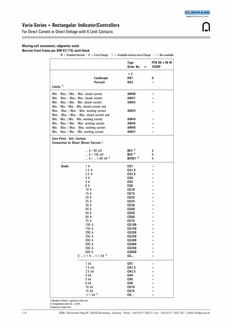
114 GMW · Kleinreuther Weg 88 · 90408 Nuremberg · Germany · Phone: +49 (0) 911 3502-0 · Fax: +49 (0) 911 3502-307 · E-Mail: [email protected]
Vario-Series • Rectangular Indicator/ControllersFor Direct Current or Direct Voltage with 4 Limit Contacts
Moving-coil movement, edgewise scaleNarrow front frame per DIN 43 718, matt black
‘N’ = Standard Version · ‘A’ = Extra Charge · ‘+’ = Available without extra Charge · ‘–’ = Not available
Type PFN 96 x 48 MOrder No. ⇒ 2596P
+⇓Landscape HQ1 NPortrait HQ2 +
Limits 1)
Min. - Max. / Min. - Max. closed current AM40 +Min. - Max. / Max.- Max. closed current AM41 +Min. - Max. / Min. - Min. closed current AM42 +Min. - Min. / Min. - Min. closed current andMax. - Max. / Max. - Max. working current AM43 +Max. - Max. / Max. - Max. closed current andMin. - Min. / Min. - Min. working current AM44 +Min. - Max. / Min. - Max. working current AM45 +Min. - Max. / Max. - Max. working current AM46 +Min. - Max. / Min. - Min. working current AM47 +
Zero Point - left / bottomConnection to Shunt (Direct Current )
... A / 60 mV BE3 2) A
... A / 150 mV BE4 2) A
... A / ...>60 mV 3) BE981 2) A
Scale: 1 A CG1 +1.5 A CG1.5 +2.5 A CG2.5 +4 A CG4 +5 A CG5 +6 A CG6 +10 A CG10 +15 A CG15 +20 A CG20 +25 A CG25 +30 A CG30 +40 A CG40 +50 A CG50 +60 A CG60 +75 A CG75 +100 A CG100 +150 A CG150 +200 A CG200 +250 A CG250 +300 A CG300 +400 A CG400 +500 A CG350 +600 A CG600 +
0 ...>1 A ...<1 kA 3) CG... +
1 kA CH1 +1.5 kA CH1.5 +2.5 kA CH2.5 +4 kA CH4 +5 kA CH5 +6 kA CH6 +10 kA CH10 +15 kA CH15 +>1 kA 3) CH... +
1) Number of limits - specify in clear text2) Complement with CG... or CH...3) Specify in clear text
wwwwww.klinkmann.com

GMW · Kleinreuther Weg 88 · 90408 Nuremberg · Germany · Phone: +49 (0) 911 3502-0 · Fax: +49 (0) 911 3502-307 · E-Mail: [email protected] 115
Vario-Series • Rectangular Indicator/ControllersFor Direct Current or Direct Voltage with 4 Limit Contacts
Moving-coil movement, edgewise scaleNarrow front frame per DIN 43 718, matt black
‘N’ = Standard Version · ‘A’ = Extra Charge · ‘+’ = Available without extra Charge · ‘–’ = Not available
Type PFN 96 x 48 MOrder No. ⇒ 2596P
+⇓Landscape HQ1 NPortrait HQ2 +
Limits 1)
Min. - Max. / Min. - Max. closed current AM40 +Min. - Max. / Max.- Max. closed current AM41 +Min. - Max. / Min. - Min. closed current AM42 +Min. - Min. / Min. - Min. closed current andMax. - Max. / Max. - Max. working current AM43 +Max. - Max. / Max. - Max. closed current andMin. - Min. / Min. - Min. working current AM44 +Min. - Max. / Min. - Max. working current AM45 +Min. - Max. / Max. - Max. working current AM46 +Min. - Max. / Min. - Min. working current AM47 +
Zero Point - left / bottomDirect Voltage
Range0 ... 60 mV DB60 A0 ...100 mV DB100 A0 ...150 mV DB150 A0 ... 250 mV DB250 A0 ... 400 mV DB400 A0 ... 600 mV DB600 A
0 ...>60 mV...<1 V 2) DB... A
0 ... 1 V DC1 A0 ... 1.5 V DC1.5 A0 ... 2.5 V DC2.5 A0 ... 4 V DC4 A0 ... 5 V DC5 A0 ... 6 V DC6 A0 ... 10 V DC10 A0 ... 15 V DC15 A0 ... 20 V DC20 A0 ... 25 V DC25 A0 ... 40 V DC40 A0 ... 50 V DC50 A0 ... 60 V DC60 A0 ... 100 V DC100 A0 ... 150 V DC150 A0 ... 250 V DC250 A0 ... 400 V DC400 A0 ... 500 V DC500 A0 ... 600 V DC600 A
0 ...>1 V ...<600 V 2) DC... A
Measuring Inputsfor thermocouple J, K, S ... / Pt100
Ranges and versions on request
1) Number of limits - specify in clear text2) Specify in clear text
wwwwww.klinkmann.com

116 GMW · Kleinreuther Weg 88 · 90408 Nuremberg · Germany · Phone: +49 (0) 911 3502-0 · Fax: +49 (0) 911 3502-307 · E-Mail: [email protected]
Vario-Series • Rectangular Indicator/ControllersFor Direct Current or Direct Voltage with 4 Limit Contacts
Moving-coil movement, edgewise scaleNarrow front frame per DIN 43 718, matt blackPlease note when ordering:Only one Identification No. with the same letter sequence may be chosen. Order No. with Identification No. N (standard model) can be left out.
‘N’ = Standard Version · ‘A’ = Extra Charge · ‘+’ = Available without extra Charge · ‘–’ = Not available
Type PFN 96 x 48 MOrder No. ⇒ 2596P
+⇓Landscape HQ1 NPortrait HQ2 +
GENERAL VARIANTSZero PointZero point at left (landscape) BC1 NZero point at bottom (portrait) BC4 +Zero point at the center BC2 AZero point between bottom and center of scale 1) BC21 A
Position of UseControl panel vertical LA1 NControl panel horizontal LA2 +Other LA999 A
(Please specify angle between scale and horizontal)
OUTPUT VARIANTSRelay output AU1 NLogic output (open collector) AU2 +H = + 24 V (electrically isolated from UH)L < + 1 V, I ≤ 25 mA at UH 20 ... 40 V DC/ACI ≤ 10 mA at UH 90 ... 127 V AC u+and UH 198 ... 267 V AC
AUXILIARY VOLTAGE VARIANTS20...40 V DC / AC, 45...65 Hz IV62 N90...127 V AC, 45...65 Hz IV60 A198...267 V AC, 45...65 Hz IV61 A
SCALE VARIANTS Division and Pointer
Single division GD1 NDouble division 1) GD2 A
Additional ImprintSecond numbering, black 1) SK982 ASecon numbering, red (RAL 2002) 1) SK983 AInscriptionWithout additional inscription SM99 NInscription ≤15 characters German 1) SM991 AInscription ≤15 characters other language 1) SM993 A
(Latin lettering)Coloured mark red RAL 2002 1) ST981 AColoured sector red (RAL 2002) 1) SU981 AColoured sector green (RAL 6018) 1) SU982 A
HOUSING VARIANTSApplicationStandard version LB99 NTropic resistant LB1 A
ProtectionStandard (see technical data) LH99 NHousing panel IP 54, connections IP 20 LH22 A
Front Frame ColourMatt black MA2 NMatt grey, RAL 7037 MA11 A
Glass WindowStandard version MG99 NAnti-glare glass MG1 A
IdentificationWithout indentification MZ99 NIdentification on the back 1) MZ998 A
1) Specify in clear text
wwwwww.klinkmann.com

GMW · Kleinreuther Weg 88 · 90408 Nuremberg · Germany · Phone: +49 (0) 911 3502-0 · Fax: +49 (0) 911 3502-307 · E-Mail: [email protected] 117
Vario-Series • Special Panel MetersSwitch Position Indicator for Direct Voltage or Alternating Voltage 45...65 Hz
Front frame gloss black
Technical Data
Front Dimensions mm 25 x 25 ∅ 25 ∅ 32 1)
Type STQ 1 ST 1 ST 2
Weight approx. (kg) 0.07 0.07 0.07Operating Voltage 300 V 300 V 300 VTest Voltage 3.5 kV 3.5 kV 3.5 kVFront Housing-Panel Protection IP 52 IP 52 IP 52Fasteners round nut round nut round nut
1) Snap-on front frame included (36 x 36 mm)
DescriptionSwitch position indicator for remote indication of contact positions at power plants andswitching stations. Can also be used advantageously as an indicator in mimic diagrams.
DisplayThree different displays are included: “Off“, “On“ and “Error“ or “Disabled“.
Mechanical DesignHousing Material PolycarbonateTerminals tab connectors, 2.8 x 0.8 mmContact Protection Available as option
Basic Dimensions
Front Panel DimensionsFront frame snaps on 32 mm
diameter front ring
ST1
Tab Connector for B2.8-1 DIN 46245 sleeves
Max. Terminal Cross Section: 1.5 mm2
Panel Cutout Isolating Contact
black print
no printing
white print
wwwwww.klinkmann.com

118 GMW · Kleinreuther Weg 88 · 90408 Nuremberg · Germany · Phone: +49 (0) 911 3502-0 · Fax: +49 (0) 911 3502-307 · E-Mail: [email protected]
Vario-Series • Special Panel MetersSwitch Position Indicator for Direct Voltage or Alternating Voltage 45...65 Hz
Graphic Symbols Schematic Diagrams
Type STQ 1 ST 1 ST 2Front Dim. mm 25 x 25 ∅∅∅∅∅ 25 ∅∅∅∅∅ 32
Order No. ⇒ 1108B 1280B 1281B
+⇓
Direct Voltage 1) B1 + + +24 V (0.3 W) IL224 + + +48 V (0.3 W) IL248 + + +60 V (0.4 W) IL260 + + +110 V (0.6 W) IL511 + + +125 V (0.7 W) IL512 + + +220 V (1.0 W) IL522 + + +
Alternating Voltage 1) B2 A A A24 V (0.3 VA) IL624 + + +48 V (0.3 VA) IL648 + + +60 V (0.4 VA) IL660 + + +110 V (0.6 VA) IL311 + + +220/230 V (1.4 VA) IL726 + + +
Movement Variants 2)
with parallel load IN1 A A A
Scale Variants 2)
with isolation contact GA2 + + +
Housing Variants 2)
Tropic resistant LB1 A A Afull contact protection VB2 A A A
Please note when ordering:Only one Identification No. with the same letter sequence may be chosen. Order No. with Identification No. N (standard model) can be left out.
‘N’ = Standard Version · ‘A’ = Extra Charge · ‘+’ = Available without extra Charge · ‘–’ = Not available
1) Nominal voltage tolerance: ±20 %2) Applies to all types for direct and alternating voltage
Ordering Example:Contact position indicator, front dimension ∅25 mmfor Alternating Voltage 220 / 230 V
Techn. Data Order No. Typ: ST1 1280B, B2, IL726
Off On Error Direct Voltage Direct Voltage,Parallel Load
Alternating Voltage Alternating Voltage,Parallel Load
wwwwww.klinkmann.com

GMW · Kleinreuther Weg 88 · 90408 Nuremberg · Germany · Phone: +49 (0) 911 3502-0 · Fax: +49 (0) 911 3502-307 · E-Mail: [email protected] 119
Vario-Series • AccessoriesLow Voltage Current Transformers, Class 1 and 0.5
Current TransformersWound- Primary Current Transformers
DescriptionCurrent transformers for direct mounting to bus bars or insulated round conductor and wound-primarycurrent transformers with fixed primary coil.Application: indirect measurement of sinusoidal alternating current.
Typ ASK 31.3
Current Transformers Wound-Primary Current Transformers
Type ASK 31.3 ASK 412.4 ASK 63.4 ASK 105.6 WSK 30 WSK 40 WSK 70.6 N
For Bars up to 30 x 10 mm 40 x 12 mm 60 x 30 mm 100 x 55 mm — — —25.4 x 13 mm 30 x 15 mm 50 x 40 mm — — — —2 x 20 x 10 mm — — — — — —
For Round Conductors to ∅ 26 mm ∅ 30.5 mm ∅ 44 mm ∅ 55 mm — — —
Rated Primary 50 to 750 A 50 to 1000 A 750 to 2000 A 1500 to 4000 A 1 to 20 A 1 to 40 A 30 to 150 ACurrent (Cl. 0.5 as of 100 A) (Cl. 0.5 as of 100 A)
Class 1 or 0.5 1 or 0.5 1 or 0.5 1 or 0.5 1 or 0.5 1 or 0.5 1 or 0.5
Housing Material polycarbonate polycarbonate polycarbonate polycarbonate polycarbonate polycarbonate polycarbonate
Transformer Width 60 mm 70 mm 95 mm 129 mm 60 mm 70 mm 70 mm 1)
Max. Weight 0.28 0.45 0.41 1.2 0.25 0.4 0.5
Technical Data, Chracteristics Values
Polycarbonate housing per UL 94 V-0
Angle bracket and rail Screw Clip Screws with insulated protective cover as standard mount (rail Screw Clip Screws only with current transformer)
Tighthening torque for rail Screw Clip Screws 2 ... 3 Nm
Maximum device voltage Um (RMS value) =max. allowable operating voltage 0.72 kV
Rated short-time alternating withstand voltage (RMS value) =test voltage 3 kV
Ambient temperature (operating temperature range) — 5 ... 40 °C (no condensation)
Design applies for 40 °C ambient temperature and70 °C bus bar temperature
Rated thermal continous current 1.0 x IN
Rated frequency 50 — 60 Hz
Rated thermal short-time current 60 x IN
Insulation class E
Overcurrent limiting factor (FS) FS 5 to 1500 A rated primary currentFS 10 from 1600 A rated primary current
Regulations and StandardsIEC 185 /DIN VDE 0414 part 1BGV A2VDE 0106 part 100/DIN 57106 part 100 (safe from finger-touch)
wwwwww.klinkmann.com

120 GMW · Kleinreuther Weg 88 · 90408 Nuremberg · Germany · Phone: +49 (0) 911 3502-0 · Fax: +49 (0) 911 3502-307 · E-Mail: [email protected]
Vario-Series • AccessoriesLow Voltage Current Transformers, Class 1 and 0.5
Type ASK 31.3 Current Transformer
Primary Conductor 30 x 10 mm25.4 x 13 mm2 x 20 x 10 mm
Round Conductor ∅ 26 mm
Transformer Width 60 mm
Rated Class 1 Class 0.5 Primary Current Sec. 5 A Sec. 1 A Sec. 5 A Sec.1 A
Order No. Order No. Order No. Order No.
1715V 1715V 1715V 1715VA VA +⇓ +⇓ +⇓ +⇓
50 1.0 0100 1100 — —60 1.0 0110 1110 — —75 1.5 0120 1120 — —80 2.5 0130 1130 — —
100 2.5 0140 1140 2140 3140150 2.5 0150 1150 2150 3150200 5 0160 1160 2160 3160250 5 — — 2170 3170250 10 0170 1170 — —300 5 — — 2180 3180300 10 0180 1180 — —400 5 — — 2190 3190400 10 0190 1190 — —500 10 0200 1200 2200 3200600 10 0210 1210 2210 3210750 10 0220 1220 2220 3220
Rated frequency 400 Hz, extra charge = specify in clear text
Accessories: Order No.
Adaptor for 35 mm mounting rail to DIN EN 50022 1722V9010
Protective Cover 1722V9110
Dimensional Drawing
wwwwww.klinkmann.com

GMW · Kleinreuther Weg 88 · 90408 Nuremberg · Germany · Phone: +49 (0) 911 3502-0 · Fax: +49 (0) 911 3502-307 · E-Mail: [email protected] 121
Vario-Series • AccessoriesLow Voltage Current Transformers, Class 1 and 0.5
Type ASK 412.4 Current Transformer
Primary Conductor 40 x 12 mm30 x 15 mm
Round Conductor ∅ 30.5 mm
Transformer Width 70 mm
Rated Class 1 Class 0.5 Primary Current Sec. 5 A Sec. 1 A Sec. 5 A Sec.1 A
Order No. Order No. Order No. Order No.
1716V 1716V 1716V 1716VA VA +⇓ +⇓ +⇓ +⇓
50 1.5 0100 1100 — —60 1.5 0110 1110 — —75 2.5 0120 1120 — —80 2.5 0130 1130 — —
100 1.5 — — 2140 3140100 3.75 0140 1140 — —150 2.5 — — 2150 3150150 5 0150 1150 — —200 2.5 — — 2160 3160200 10 0160 1160 — —250 5 — — 2170 3170250 10 0170 1170 — —300 5 — — 2180 3180300 10 0180 1180 — —400 10 0190 1190 2190 3190500 10 0200 1200 2200 3200600 10 0210 1210 2210 3210750 10 0220 1220 2220 3220800 10 0230 1230 2230 3230
1000 10 0240 1240 2240 3240
Rated frequency 400 Hz, extra charge = specify in clear text
Accessories Order No.
Adaptor for 35 mm mounting rail to DIN EN 50022 1722V9020
Protective Cover 1722V9120
Dimensional Drawing
wwwwww.klinkmann.com

122 GMW · Kleinreuther Weg 88 · 90408 Nuremberg · Germany · Phone: +49 (0) 911 3502-0 · Fax: +49 (0) 911 3502-307 · E-Mail: [email protected]
Vario-Series • AccessoriesLow Voltage Current Transformers, Class 1 and 0.5
Type ASK 63.4 Current Transformer
Primary Conductor 60 x 30 mm50 x 40 mm
Round Conductor ∅ 44 mm
Transformer Width 95 mm
Rated Class 1 Class 0.5 Primary Current Sec. 5 A Sec. 1 A Sec. 5 A Sec.1 A
Order No. Order No. Order No. Order No.
1717V 1717V 1717V 1717VA VA +⇓ +⇓ +⇓ +⇓
750 10 0220 1220 2220 3220800 10 0230 1230 2230 3230
1000 10 0240 1240 2240 32401200 10 0250 1250 2250 32501500 10 0260 1260 2260 32601800 10 0270 1270 2270 32702000 10 0280 1280 2280 3280
Rated frequency 400 Hz, extra charge = specify in clear text
Accessories: Order No.
Protective Cover 1722V9130
Dimensional Drawing
wwwwww.klinkmann.com

GMW · Kleinreuther Weg 88 · 90408 Nuremberg · Germany · Phone: +49 (0) 911 3502-0 · Fax: +49 (0) 911 3502-307 · E-Mail: [email protected] 123
Vario-Series • AccessoriesLow Voltage Current Transformers, Class 1 and 0.5
Type ASK 105.6 Current Transformer
Primary Conductor 100 x 55 mm
Round Conductor ∅ 55 mm
Transformer Width 129 mm
Rated Class 1 Class 0.5 Primary Current Sec. 5 A Sec. 1 A Sec. 5 A Sec.1 A
Order No. Order No.. Order No. Order No.
1718V 1718V 1718V 1718VA VA +⇓ +⇓ +⇓ +⇓
1500 10 0260 1260 2260 32601800 10 0270 1270 2270 32702000 10 0280 1280 2280 32802500 10 0290 1290 2290 32903000 10 0300 1300 2300 33004000 10 0310 1310 2310 3310
Rated frequency 400 Hz, extra charge = specify in clear text
Accessories: Order No.
Protective Cover 1722V9130
Dimensional Drawing
wwwwww.klinkmann.com
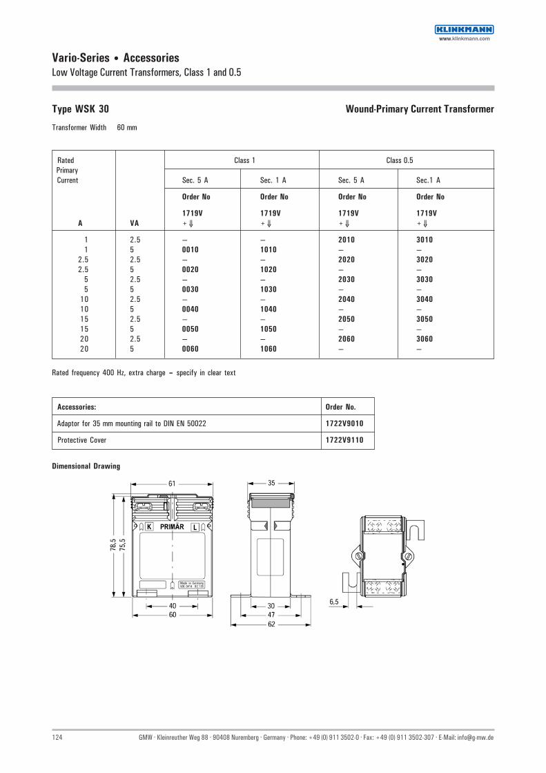
124 GMW · Kleinreuther Weg 88 · 90408 Nuremberg · Germany · Phone: +49 (0) 911 3502-0 · Fax: +49 (0) 911 3502-307 · E-Mail: [email protected]
Vario-Series • AccessoriesLow Voltage Current Transformers, Class 1 and 0.5
Type WSK 30 Wound-Primary Current Transformer
Transformer Width 60 mm
Rated Class 1 Class 0.5 Primary Current Sec. 5 A Sec. 1 A Sec. 5 A Sec.1 A
Order No Order No Order No Order No
1719V 1719V 1719V 1719VA VA +⇓ +⇓ +⇓ +⇓
1 2.5 — — 2010 30101 5 0010 1010 — —
2.5 2.5 — — 2020 30202.5 5 0020 1020 — —
5 2.5 — — 2030 30305 5 0030 1030 — —
10 2.5 — — 2040 304010 5 0040 1040 — —15 2.5 — — 2050 305015 5 0050 1050 — —20 2.5 — — 2060 306020 5 0060 1060 — —
Rated frequency 400 Hz, extra charge = specify in clear text
Accessories: Order No.
Adaptor for 35 mm mounting rail to DIN EN 50022 1722V9010
Protective Cover 1722V9110
Dimensional Drawing
wwwwww.klinkmann.com

GMW · Kleinreuther Weg 88 · 90408 Nuremberg · Germany · Phone: +49 (0) 911 3502-0 · Fax: +49 (0) 911 3502-307 · E-Mail: [email protected] 125
Vario-Series • AccessoriesLow Voltage Current Transformers, Class 1 and 0.5
Type WSK 40 Wound-Primary Current Transformer
Transformer Width 70 mm
Rated Class 1 Class 0.5 Primary Current Sec. 5 A Sec. 1 A Sec. 5 A Sec.1 A
Order No. Order No. Order No. Order No.
1720V 1720V 1720V 1720VA VA +⇓ +⇓ +⇓ +⇓
1 10 0010 1010 2010 30102.5 10 0020 1020 2020 3020
5 10 0030 1030 2030 303010 10 0040 1040 2040 304015 10 0050 1050 2050 305020 10 0060 1060 2060 306025 10 0070 1070 2070 307030 5 — — 2080 308030 10 0080 1080 — —40 5 — — 2090 309040 10 0090 1090 — —
Rated frequency 400 Hz, extra charge = specify in clear text
Accessories: Order No.
Adaptor for 35 mm mounting rail to DIN EN 50022 1722V9020
Protective Cover 1722V9120
Dimensional Drawing
wwwwww.klinkmann.com

126 GMW · Kleinreuther Weg 88 · 90408 Nuremberg · Germany · Phone: +49 (0) 911 3502-0 · Fax: +49 (0) 911 3502-307 · E-Mail: [email protected]
Vario-Series • AccessoriesLow Voltage Current Transformers, Class 1 and 0.5
Type WSK 70.6 N Wound-Primary Current Transformer
Transformer Width 70 mm
Rated Class 1 Class 0.5 Primary Current Sec. 5 A Sec. 1 A Sec. 5 A Sec.1 A
Order No. Order No. Order No. Order No.
1721V 1721V 1721V 1721VA VA +⇓ +⇓ +⇓ +⇓
30 10 0080 1080 2080 308040 10 0090 1090 2090 309050 10 0100 1100 2100 310060 10 0110 1110 2110 311075 10 0120 1120 2120 312080 10 0130 1130 2130 3130
100 10 0140 1140 2140 3140150 10 0150 1150 2150 3150
Rated frequency 400 Hz, extra charge = specify in clear text
Dimensional Drawing
Accessories: Order No.
Protective Cover 1722V9120
Layout:
Primary terminals K and LCopper rail 20 x 5
with M 8 x 25 DIN 933 ≤100 Awith M10 x 30 DIN 933 >100 A
wwwwww.klinkmann.com

GMW · Kleinreuther Weg 88 · 90408 Nuremberg · Germany · Phone: +49 (0) 911 3502-0 · Fax: +49 (0) 911 3502-307 · E-Mail: [email protected] 127
Vario-Series • AccessoriesShunt Resistors, Class 0.5
Shunt Resistor, 250 A / 60 mV
Technical Data
Type 60 mV 150 mV
Accuracy Class 0.5 0.5per DIN EN 60051
Dimensions per DIN 43703 1)
Balancing An instrument power consumptionvalue of 6 mA is taken intoconsideration for balancing whenshunt resistors are used
1) Model with insulation base can be screw or snap mounted (for top-hat rail per DINEN 50022-35), overall length: 140 mm. Overall height for model with cover isincreased to 40.5 mm.
Ordering Example
Techn. data Order No.
Shunt Resistor, Nominal Current IN 250 A. 1700V3340Voltage Drop 60 mV
Nominal Current 60 mV Nominal Current 150 mV
IN Weigth approx. (kg) Order No. IN Weigth approx. (kg) Order No.
1 A 0.10 1700V3010 ◊ 1 A 0.10 1700V4010 ◊1.5 A 0.10 1700V3030 ◊ 1.5 A 0.10 1700V4030 ◊2.5 A 0.10 1700V3050 ◊ 2.5 A 0.10 1700V4050 ◊
4 A 0.10 1700V3070 ◊ 4 A 0.10 1700V4070 ◊6 A 0.10 1700V3090 ◊ 6 A 0.10 1700V4090 ◊
10 A 0.10 1700V3110 ◊ 10 A 0.10 1700V4110 ◊15 A 0.10 1700V3130 ◊ 15 A 0.10 1700V4130 ◊25 A 0.10 1700V3170 ◊ 25 A 0.10 1700V4170 ◊40 A 0.10 1700V3200 40 A 0.14 1700V420060 A 0.10 1700V3230 60 A 0.15 1700V4230
100 A 0.10 1700V3280 100 A 0.17 1700V4280150 A 0.15 1700V3300 150 A 0.20 1700V4300250 A 0.50 1700V3340 250 A 0.70 1700V4340400 A 0.70 1700V3370 400 A 1.10 1700V4370500 A 1.00 1700V3390 500 A 1.10 1700V4390600 A 1.20 1700V3400 600 A 1.70 1700V4400
1 kA 1.45 1700V3460 1 kA 2.50 1700V44601.5 kA 1.95 1700V3480 1.5 kA 3.70 1700V44802.5 kA 2.90 1700V3520 2.5 kA 5.20 1700V4520
4 kA 4.20 1700V3550 4 kA 8.30 1700V45505 kA 4.30 1700V3570 5 kA 10.60 1700V45706 kA 10.50 1700V3580 6 kA 15.00 1700V4580
10 kA 21.00 1700V3630 10 kA 28.00 1700V463015 kA 32.00 1700V3650
Nominal Current 60 mVIN
Order No.
40 A 1700V7200 ◊
60 A 1700V7230 ◊
100 A 1700V7280 ◊
150 A 1700V7300 ◊
◊ On insulating base (screws or snaps onto top-hat rail per DIN EN 50 022-35)
◊ Cover for shunt resistor on insulating base: Order No. 1700V8210
One Pair Cables with Cable Lugs 2)
Length Cross-Section Cable Order No.per VDE 0281 part 401
1.3 m 0.75 mm2 H03V-H 1700V80102.6 m 1.5 mm2 H07V-H 1700V80204.3 m 2.5 mm2 H07V-H 1700V80307.0 m 4.0 mm2 H07V-H 1700V804010.5 m 6.0 mm2 H07V-H 1700V8050
2) 0.06 Ω cable resistance per cable pair
wwwwww.klinkmann.com

128 GMW · Kleinreuther Weg 88 · 90408 Nuremberg · Germany · Phone: +49 (0) 911 3502-0 · Fax: +49 (0) 911 3502-307 · E-Mail: [email protected]
Vario-Series • AccessoriesShunt Resistors, Class 0.5
Drawings to Scale
Insulating base only up to 25 A
Max
imum
lim
it
Form A Form B
Dimensions in mm
Lock washer or springwasher per DIN127
Form C
Description for shunt resistor for 60 mV voltage drop and 25 A rated current:
Voltage Drop mV Dim.
Shunt Resistor 60/25 DIN EN 60051
For rated current in A
Number of supply terminals
Hexagonal bolt DIN 933-5
Washer DIN 125 - mild steel
Nut DIN 934-5
Voltage terminals 2 socket-head capscrews AM 5 x 8 DIN 84-4 and washer 5.3 DIN 433, mild steel
Unspecified details are to be selected appropriate.Accuracy class 0.5 per DIN 57 410, rules for measuring instruments.Shunts exchangeable, if power consumption of measuring instrument connected does not exceed 500 µW.1) To maintain a constant contact pressure, place a lock washer or a spring washer between the washer and the nut2) For 150 mV: bolt M 16 x 60 3) For 150 mV: bolt M 20 x 604) For 150 mV: bolt M 20 x 755) When bolts M 5 and M 8 are available, use preferably M 5 per DIN 267
wwwwww.klinkmann.com

GMW · Kleinreuther Weg 88 · 90408 Nuremberg · Germany · Phone: +49 (0) 911 3502-0 · Fax: +49 (0) 911 3502-307 · E-Mail: [email protected] 129
Vario-Series • AccessoriesVoltage Divider for Direct Voltage
DescriptionVoltage divider for direct voltage meters, made of film resistors. For Usage in single-ended high voltage facilities up to 10 kV.Design of the test circuit: At full scale deflection of the meter, 250 µA each passthrough the protective resistor an the meter.25 V are impressed on the indicator.
Voltage divider for direct voltage,Can be combined with any moving-coil type
Technical Data
Design Film resistors with porcelain insulators onpressed paper sheet
Mounting on isolater necessary
Weight approx. (kg) 0.2Protection IP 00Resistor ca. 2 kΩ/V (voltage divider in comb. with moving-coil meter)Terminals can be connected to any moving-coil voltmeter
Schematic Diagram... kV
Basic Dimensions Order InformationVoltage Divider for Direct Current 25 V / 250 µA
Type SP Scale-Order No. Order No.
Nominal Voltage ⇓ +⇓
1000 V 48900 13370 DH11500 V 48900 13390 DH1.52000 V 48900 13400 DH22500 V 48900 13410 DH2.53000 V 48900 13420 DH34000 V 48900 13430 DH45000 V 48900 13440 DH56000 V 48900 13450 DH6
10000 V 48900 13460 DH10
SP
Ordering Example for Meters with Voltage Divider:
Techn. Data Order No.
Square Panel Meterwith moving-coil movement V-PQS 96 1604P, BE76, DH1Measuring range 0-1 kV
example
wwwwww.klinkmann.com

130 GMW · Kleinreuther Weg 88 · 90408 Nuremberg · Germany · Phone: +49 (0) 911 3502-0 · Fax: +49 (0) 911 3502-307 · E-Mail: [email protected]
Vario-Series • AccessoriesPower Supply Unit for Indicator/Controllers
Technical Data
Type NG 24/200-1 NG 24/200-1 NG 24/200-2Order No. 49900 09610 49900 09630 49900 09640
Weigth approx. (kg) 0.5Max. Operating Voltage 300 VTest Voltage 3.5 kVProtection (Terminals) IP 10
Input 230 V AC (198 ... 242 V) 45 ... 65 Hz 115 V AC (99 ... 121 V) 45 ... 65 Hz 24 V AC (21.6 ... 26.4 V) 45 ... 400 Hz
Output 24 V DC ±20 %Max. output current 200 mARipple ≤ 3 Vss;Without electrical isolation;Protection from short circuit
NG 24/200-1
DescriptionDue to the compact design of indicator/controllers with smaller sizes, a built in powersupply, that differs from the necessary 24 V direct voltage is not realisable.Therefore GMW developed power supplies that enable the user to accomodate anindividual auxiliary voltage supply according to the available supply voltage and thenecessary power consumption of the the indicator/controller.
Basic Dimensions
wwwwww.klinkmann.com

GMW · Kleinreuther Weg 88 · 90408 Nuremberg · Germany · Phone: +49 (0) 911 3502-0 · Fax: +49 (0) 911 3502-307 · E-Mail: [email protected] 131
Vario-Series • Accessories and Spare PartsBlanking Plates, Protective Caps, Rubber Seals
Type Order No.⇓ ⇓
BLANKING PLATESNarrow-frame types
clear, palin glass Q 48 S 27863 15945Q 72 S 27863 15900Q 96 S 27863 15905Q 144 S 27863 15915PF 72 x 36 27863 15920PFN 96 x 48 27863 15925PF 144 x 72 27863 15930
opaque, white plastic Q 48 S 27863 15946Q 72 S 27863 15901Q 96 S 27863 15906Q 144 S 27863 15916PF 72 x 36 27863 15921PFN 96 x 48 27863 15926PF 144 x 72 27863 15931
opaque, black plastic Q 48 S 27863 15948Q 72 S 27863 15903Q 96 S 27863 15908
PROTECTIVE COVERPlexiglass protective cover PR 144 x 36 32512 86760for front housing-panel protection IP 54
RUBBER SEAL(Mounting with screw clamp necessary)
Q 48 1799V2290Q 72 1799V2230
for versions with narrow front frames – Q 96 S 1799V2240for tropic resistant versions – Q 96 1799V2260
Q 144 1799V2250PF 72 x 36 35235 86120PFN 96 x 48 35235 86125PF 144 x 72 35235 86130
CLEAR PROTECTIVE COVERwith rubber seal for front housing-panel Q 48 27863 15955protection IP 65 Q 72 27863 15950
Q 96 27863 15960
Blanking Plates, protective covers, rubber seals,Clear cover with rubber seal for IP 65
wwwwww.klinkmann.com
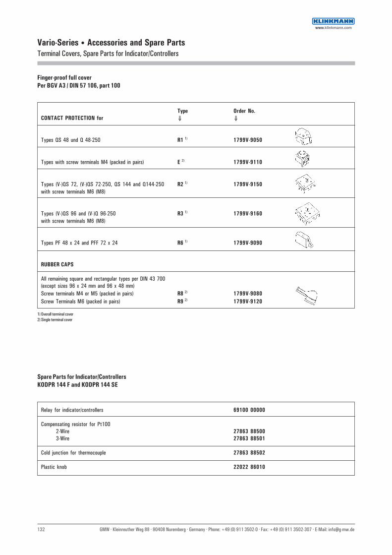
132 GMW · Kleinreuther Weg 88 · 90408 Nuremberg · Germany · Phone: +49 (0) 911 3502-0 · Fax: +49 (0) 911 3502-307 · E-Mail: [email protected]
Vario-Series • Accessories and Spare PartsTerminal Covers, Spare Parts for Indicator/Controllers
Finger-proof full coverPer BGV A3 / DIN 57 106, part 100
Type Order No.CONTACT PROTECTION for ⇓ ⇓
Types QS 48 und Q 48-250 R1 1) 1799V-9050
Types with screw terminals M4 (packed in pairs) E 2) 1799V-9110
Types (V-)QS 72, (V-)QS 72-250, QS 144 and Q144-250 R2 1) 1799V-9150with screw terminals M6 (M8)
Types (V-)QS 96 and (V-)Q 96-250 R3 1) 1799V-9160with screw terminals M6 (M8)
Types PF 48 x 24 and PFF 72 x 24 R6 1) 1799V-9090
RUBBER CAPS
All remaining square and rectangular types per DIN 43 700(except sizes 96 x 24 mm and 96 x 48 mm)Screw terminals M4 or M5 (packed in pairs) R8 2) 1799V-9080Screw Terminals M6 (packed in pairs) R9 2) 1799V-9120
Spare Parts for Indicator/ControllersKODPR 144 F and KODPR 144 SE
Relay for indicator/controllers 69100 00000
Compensating resistor for Pt1002-Wire 27863 885003-Wire 27863 88501
Cold junction for thermocouple 27863 88502
Plastic knob 22022 86010
1) Overall terminal cover2) Single terminal cover
wwwwww.klinkmann.com
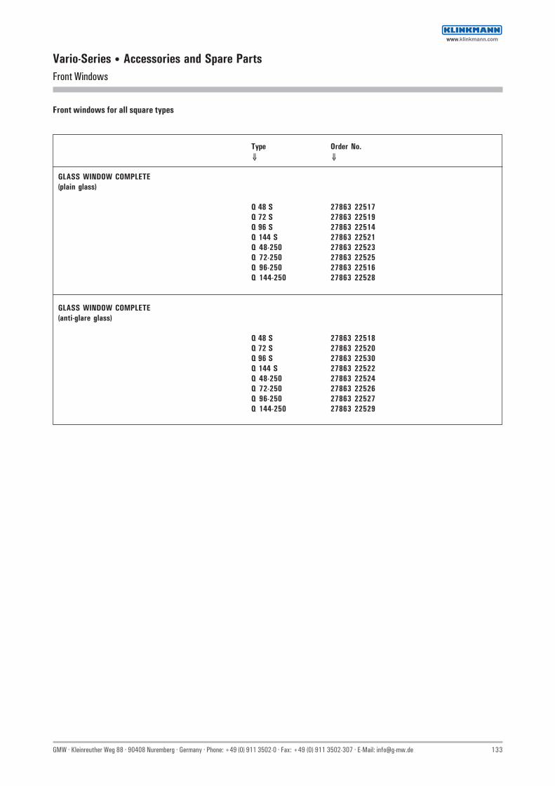
GMW · Kleinreuther Weg 88 · 90408 Nuremberg · Germany · Phone: +49 (0) 911 3502-0 · Fax: +49 (0) 911 3502-307 · E-Mail: [email protected] 133
Vario-Series • Accessories and Spare PartsFront Windows
Type Order No.⇓ ⇓
GLASS WINDOW COMPLETE(plain glass)
Q 48 S 27863 22517Q 72 S 27863 22519Q 96 S 27863 22514Q 144 S 27863 22521Q 48-250 27863 22523Q 72-250 27863 22525Q 96-250 27863 22516Q 144-250 27863 22528
GLASS WINDOW COMPLETE(anti-glare glass)
Q 48 S 27863 22518Q 72 S 27863 22520Q 96 S 27863 22530Q 144 S 27863 22522Q 48-250 27863 22524Q 72-250 27863 22526Q 96-250 27863 22527Q 144-250 27863 22529
Front windows for all square types
wwwwww.klinkmann.com

134 GMW · Kleinreuther Weg 88 · 90408 Nuremberg · Germany · Phone: +49 (0) 911 3502-0 · Fax: +49 (0) 911 3502-307 · E-Mail: [email protected]
IndexOrder Number Index
Order No. TypeCatalogue Page
Price List
Price List Page
1108B STQ 1 117 AV 251115D V-LM 96-250 78 AV 151129D V-LM 96 78 AV 151129H V-LF 96 82 AV 161194P PFF 00 97 AV 201196P PFF 0 97 AV 201280B ST 1 117 AV 251281B ST 2 117 AV 251505P PF 72x36 89 AV 181511P PF 48x24 89 AV 181515P PFF 72x24 97 AV 211524P PFFN 96x24 97 AV 211584P PF 144x72 89 AV 191594P PFN 96x48 89 AV 191601E V-AQS 72 36 AV 51601M V-MQS 72 44 AV 71601P V-PQS 72 62 AV 121601W V-PQS 72 54 AV 81601Z V-FZQS 72 84 AV 161602P V-PQ 72-250 70 AV 141602W V-PQ 72-250 54 AV 101603C V-MAQS 72 49 AV 71604E V-AQS 96 36 AV 61604M V-MQS 96 44 AV 71604P V-PQS 96 62 AV 121604W V-PQS 96 54 AV 81604Z V-FZQS 96 84 AV 171605P V-PQ 96-250 70 AV 141605W V-PQ 96-250 54 AV 101606C V-MAQS 96 49 AV 71620E AQS 144 36 AV 61620M MQS 144 44 AV 71620P PQS 144 62 AV 131620W PQS 144 54 AV 91621P PQ 144-250 70 AV 151621W PQ 144-250 54 AV 111622C AMQS 144 49 AV 71662M V-MQS 48 44 AV 71668P V-PQ 48-250 70 AV 131668W V-PQ 48-250 54 AV 91670E AQS 48 W 36 AV 51670P PQS 48 W 62 AV 111670W PQ 48 W 54 AV 71670Z FZQS 48 W 84 AV 161700V… H03V-H 127 AV 321700V… H07V-H 127 AV 321700V… NW 127 AV 311700V… NW 32 AB 71715V… ASK 31.3 120 AV 261715V… ASK 31.3 30 AB 71716V… ASK 412.4 121 AV 27
Order No. TypeCatalogue Page
Price List
Price List Page
1716V… ASK 412.4 31 AB 71717V… ASK 63.4 122 AV 281718V… ASK 105.6 123 AV 291719V… WSK 30 124 AV 291720V… WSK 40 125 AV 291721V… WSK 70.6 N 126 AV 3021102… DPR 144 F 97 AV 222524P PFFN 96x24 M 105 AV 222594P PFN 96x48 M 105 AV 232596P PFN 96x48 M 111 AV 2441004 73… DQB 48 MV-P… 20 AB 541004 73… DQB 72 MV-P… 20 AB 541004 73… DQB 96 MV-P… 20 AB 548900… SP 129 AV 3349900… NG 24/200 130 AV 3355004 73… DLMQB 96-P… 18 AB 561102… KODPR 144 F 105 AV 2365102… KODPR 144 SE 105 AV 2472475 05313 B FQB 72 24 AB 596051 05… DLQB 96 22 AB 596475 05312 B FQB 96 24 AB 5
DQB 48 16 AB 5DQB 72 16 AB 5DQB 96 16 AB 5EQB 48 10 AB 5EQB 72 10 AB 5EQB 72/U6 25 AB 6EQB 96 10 AB 5EQB 96/U6 25 AB 6FkN 2 26 AB 6MEQB 72 14 AB 5MEQB 96 14 AB 5MQB 48 12 AB 5MQB 72 12 AB 5MQB 96 12 AB 5
wwwwww.klinkmann.com

GMW · Kleinreuther Weg 88 · 90408 Nuremberg · Germany · Phone: +49 (0) 911 3502-0 · Fax: +49 (0) 911 3502-307 · E-Mail: [email protected] 135
IndexType Number Index
Type Order No.Catalogue Page
Price List
Price List Page
AMQS 144 1622C 49 AV 7AQS 144 1620E 36 AV 6AQS 48 W 1670E 36 AV 5ASK 105.6 1718V… 123 AV 29ASK 31.3 1715V… 120 AV 26ASK 31.3 1715V… 30 AB 7ASK 412.4 1716V… 121 AV 27ASK 412.4 1716V… 31 AB 7ASK 63.4 1717V… 122 AV 28DLMQB 96-P… 55004 73… 18 AB 5DLQB 96 96051 05… 22 AB 5DPR 144 F 21102… 97 AV 22DQB 48 16 AB 5DQB 48 MV-P… 41004 73… 20 AB 5DQB 72 16 AB 5DQB 72 MV-P… 41004 73… 20 AB 5DQB 96 16 AB 5DQB 96 MV-P… 41004 73… 20 AB 5EQB 48 10 AB 5EQB 72 10 AB 5EQB 72/U6 25 AB 6EQB 96 10 AB 5EQB 96/U6 25 AB 6FkN 2 26 AB 6FQB 72 72475 05313 B 24 AB 5FQB 96 96475 05312 B 24 AB 5FZQS 48 W 1670Z 84 AV 16H03V-H 1700V… 127 AV 32H07V-H 1700V… 127 AV 32KODPR 144 F 61102… 105 AV 23KODPR 144 SE 65102… 105 AV 24MEQB 72 14 AB 5MEQB 96 14 AB 5MQB 48 12 AB 5MQB 72 12 AB 5MQB 96 12 AB 5MQS 144 1620M 44 AV 7NG 24/200 49900… 130 AV 33NW 1700V… 127 AV 31NW 1700V… 32 AB 7PF 144x72 1584P 89 AV 19PF 48x24 1511P 89 AV 18PF 72x36 1505P 89 AV 18PFF 0 1196P 97 AV 20PFF 00 1194P 97 AV 20PFF 72x24 1515P 97 AV 21PFFN 96x24 1524P 97 AV 21PFFN 96x24 M 2524P 105 AV 22PFN 96x48 1594P 89 AV 19PFN 96x48 M 2594P 105 AV 23PFN 96x48 M 2596P 111 AV 24
Type Order No.Catalogue Page
Price List
Price List Page
PQ 144-250 1621P 70 AV 15PQ 144-250 1621W 54 AV 11PQ 48 W 1670W 54 AV 7PQS 144 1620P 62 AV 13PQS 144 1620W 54 AV 9PQS 48 W 1670P 62 AV 11SP 48900… 129 AV 33ST 1 1280B 117 AV 25ST 2 1281B 117 AV 25STQ 1 1108B 117 AV 25V-AQS 72 1601E 36 AV 5V-AQS 96 1604E 36 AV 6V-FZQS 72 1601Z 84 AV 16V-FZQS 96 1604Z 84 AV 17V-LF 96 1129H 82 AV 16V-LM 96 1129D 78 AV 15V-LM 96-250 1115D 78 AV 15V-MAQS 72 1603C 49 AV 7V-MAQS 96 1606C 49 AV 7V-MQS 48 1662M 44 AV 7V-MQS 72 1601M 44 AV 7V-MQS 96 1604M 44 AV 7V-PQ 48-250 1668P 70 AV 13V-PQ 48-250 1668W 54 AV 9V-PQ 72-250 1602P 70 AV 14V-PQ 72-250 1602W 54 AV 10V-PQ 96-250 1605P 70 AV 14V-PQ 96-250 1605W 54 AV 10V-PQS 72 1601P 62 AV 12V-PQS 72 1601W 54 AV 8V-PQS 96 1604P 62 AV 12V-PQS 96 1604W 54 AV 8WSK 30 1719V… 124 AV 29WSK 40 1720V… 125 AV 29WSK 70.6 N 1721V… 126 AV 30
wwwwww.klinkmann.com

136 GMW · Kleinreuther Weg 88 · 90408 Nuremberg · Germany · Phone: +49 (0) 911 3502-0 · Fax: +49 (0) 911 3502-307 · E-Mail: [email protected]
Product RangeGeneral Overview
Panel Meters per DIN 43700— Alternating Current / Voltages— Direct Current / Voltages— For Thermocouples— For Resistance Thermometers— Power and Power Factor Meters— Frequency Meters (Pointer and Reed Type)— Comb. Maximum Demand Ammeter
Electrical Indicator/Controllers— Current— Voltage— Power— Frequency— Temperature
Digital Panel Meters— 3½-digit— 4½-digit— With Data Outputs— Comparator— Multifunctional Power Measuring Device
Bar-Graph Panel Meters— Direct Current / Voltage— Resistance— Frequency— Temperature
Programmable Logic Controllers (PLC) Peripheral Devices— Text Displays— Data & Graphics Printers
Electric Measuring Transducers— Alternating Current / Voltage— Thermocouples— Resistance Thermometer— Power— Power Factor— Frequency
Measuring and Test Instruments— Electrical Tester per VDE 0701 / 0702— Electrical Testers per VDE 0751
Probes for Oscilloscopes and Multimeters– Differential Probes– High Voltage Probes– HF-Probes– HF-Demodulator-Probes– SMT-Probes– Kelvin-Clamps– Measuring Tweezers and Measuring Lines
Accessories— Shunt Resistors— Current Transformers— Switches— Switch Postion Indicators— Blanking Frames
In Addition to our offer “Analog Panel Meters - Preference Program“.the following products are available (on request):
Analog panel meters from price list J(former Müller & Weigert, Neuberger)
Analog panel meters from price list Bertram(former Bertram)
Analog panel meters from price list GMC Universal(former Gossen)
Example:— Meters for ship operation (BV3340)
railway operationvehicle operationcrane operationaggregate operation
— Dual Voltmeters— Dual frequency Meters— Triple Meters— Operating Hour Meters— Moving-iron Edgewise Meters— Synchronoscopes— Combined Moving-iron / Bimetal Ammeters with Center
on one Axis— Synchro Indicators wall mounting WQ 96 or WQ 144— Moving-iron / Moving-Coil Meters for DIN Top Hat Rail
Mounting— Moving-Coil Temperature Indicator, can be conneted to Pt100
or to Thermocouples— Meters for Plant Construction / Training Sector.
available as surface-type, built-in, or base frame meters— Indicators, Mini-Meters with rectangular or round Housings
wwwwww.klinkmann.com

GMW · Kleinreuther Weg 88 · 90408 Nuremberg · Germany · Phone: +49 (0) 911 3502-0 · Fax: +49 (0) 911 3502-307 · E-Mail: [email protected] 137
Terms of delivery and payment
1. Validity– All the former lists, incl. special lists, shall be superseded by this
price list, which shall be authoritative exclusively for deliveries.– The adata given in this catalogue comprise the product
specifications. Subject to availability and technical modifications.
2. Prices– The prices quoted are valid in EURO, the applicable VAT provided by
law not included.– We reserve the right to charge a processing fee for subsequent
modifications of an order already passed.– Please note, that for orders less than 80.00 EURO in net. value a
processing fee of 18.00 EURO will apply.– We reserve the right to have orders the net order value of which is
less than 500.00 EURO performed by an authorized dealer.– The prices are valid ex factory, packing not included.– In case of resale the prices are to be considered merely as a
nonbinding price recommendation.
3. Terms of delivery and payment– Observance of the delivery dates stated in offers and order
confirmations is based on the condition that the customer fulfils hisobligations completely and in time.The General Terms of Delivery of the German Electrical Industryshall be considered as binding, if not otherwise stated in writing.
– Nuremberg shall be the place of performance.– This price list does not state the availability of items.– Payment: Unless different terms of payment were agreed upon, we
deliver to customer unknown to us only against cash on delivery orpre-payment of the invoice amount. In case of default in paymentwe reserve the right to invoice interest on arrears at a rate whichexceeds the applicable discount rate of the Land Central Bank by1%, plus bank charges.
– Reservation of title: In case of processing of our products, weobtain co-ownership of the products created by processing, inproportion to the value of our processed products at the moment ofdelivery to the total value of the item produced. In case our propertyis seized in execution, the purchaser shall be obliged to inform uswithout delay.
– Shipment: Shipment shall be effected from Nuremberg at theconsigner’s risk and on his responsibility.
– Packaging: Packaging shall be invoiced at costs.The packaging is according to the German regulations.
wwwwww.klinkmann.com

138 GMW · Kleinreuther Weg 88 · 90408 Nuremberg · Germany · Phone: +49 (0) 911 3502-0 · Fax: +49 (0) 911 3502-307 · E-Mail: [email protected]
Notice
wwwwww.klinkmann.com

Analog Panel Meters • Preference ProgramGeneral Conditions
Terms and Conditions of Sale and Delivery.Subject to “General Terms and Conditions for Products of, and ServicesRendered by the Electrical Industry” including supplementary termsregarding extended title to goods in their most current revisions.
Attention.No guarantee claims are allowed for devices which have been opened.Subject to change without notice.Graphic representations and photographs are non-binding.
Order Information.Please provide complete and unambiguous order information includingcomplete order number in order to avoid additional follow-up andmisunderstandings in the processing of orders.
Export and Customs Documents.A processing fee will be charged per document for shipping instructionswhich deviate from standard shipping procedures within the FederalRepublic of Germany, for example preparation of certificates of origin,preparation of shipping documents in foreign languages, preparation ofexport declarations etc.
Orders / Inquiries.A large number of qualified employees are available at the followingtelephone number:+49 (0)911 3502-0during the following times:Monday through Thursday from 08:00 a.m. to 04:30 p.m. andFriday from 08:00 a.m. to 3:00 p.m.
Address.GOSSEN Mueller & WeigertKleinreuther Weg 88D – 90408 NurembergGERMANYPhone: +49 (0)911 3502-0Fax: +49 (0)911 3502-307/-305E-mail: [email protected]://www.g-mw.de
Agencies.Contact addresses can be found on our website.
wwwwww.klinkmann.com

Product Table
Analog Panel Meters Measurement Transducers Digital Panel Meters
Measuring and Test Instruments Elektrical Indicator/Controllers Text Displays/Printers
Bar-Graph Panel Meters Probes Accessories
GMW_Analog_Panel_Meters_en_1211.pdf
Samaratel. +7 846 273 95 [email protected]
Yekaterinburgtel. +7 343 376 [email protected]
St. Petersburgtel. +7 812 327 [email protected]
Moscowtel. +7 495 641 [email protected]
Helsinkitel. +358 9 540 [email protected]
Vilniustel. +370 5 215 [email protected]
Rigatel. +371 6738 [email protected]
Мinsktel. +375 17 200 [email protected]
Tallinntel. +372 668 [email protected]
Кievtel. +38 044 495 33 [email protected]
www.klinkmann.com