Basic principles of vehicle dynamics
17
A body can only be made to move or change course by the action of forces. Many forces act upon a vehicle when it is being driven. An important role is played by the tires as any change of speed or direction involves forces acting on the tires. Tires Task The tire is the connecting link between the vehicle and the road. It is at that point that the safe handling of a vehicle is ultimately de- cided. The tire transmits motive, braking and lateral forces within a physical environment whose parameters define the limits of the dynamic loads to which the vehicle is subjected. The decisive criteria for the assessment of tire quality are: Straight-running ability Stable cornering properties Ability to grip on a variety of road surfaces Ability to grip in a variety of weather conditions Steering characteristics Ride comfort (vibration absorption and damping, quietness) Durability and Economy Design There are a number of different tire designs that are distinguished according to the nature and sophistication of the technology em- ployed. The design of a conventional tire is determined by the characteristics required of it in normal conditions and emergency situa- tions. Legal requirements and regulations specify which tires must be used in which conditions, the maximum speeds at which different types of tire may be used, and the criteria by which tires are classified. Radial tires In a radial tire, the type which has now be- come the standard for cars, the cords of the tire-casing plies run radially, following the shortest route from bead to bead (Fig. 1). A reinforcing belt runs around the perimeter of the relatively thin, flexible casing. 12 Basic principles of vehicle dynamics Tires Basic principles of vehicle dynamics Fig. 1 1 1 Rim bead seat 1 2 Hump 1 3 Rim flange 1 4 Casing 1 5 Air-tight rubber layer 1 6 Belt 1 7 Tread 1 8 Sidewall 1 9 Bead 10 Bead core 11 Valve 6 7 5 4 3 2 1 8 9 10 11 Structure of a radial car tire 1 æ UFR0033Y K. Reif (Ed.), Brakes, Brake Control and Driver Assistance Systems, Bosch Professional Automotive Information, DOI 10.1007/978-3-658-03978-3_2, © Springer Fachmedien Wiesbaden 2014
Transcript of Basic principles of vehicle dynamics
A body can only be made to move or changecourse by the action of forces. Many forcesact upon a vehicle when it is being driven. Animportant role is played by the tires as anychange of speed or direction involves forcesacting on the tires.
Tires
TaskThe tire is the connecting link between thevehicle and the road. It is at that point thatthe safe handling of a vehicle is ultimately de-cided. The tire transmits motive, braking andlateral forces within a physical environmentwhose parameters define the limits of the dynamic loads to which the vehicle is subjected. The decisive criteria for the assessment of tire quality are:� Straight-running ability� Stable cornering properties � Ability to grip on a variety of road surfaces� Ability to grip in a variety of weather conditions
� Steering characteristics� Ride comfort (vibration absorption and damping, quietness)
� Durability and� Economy
DesignThere are a number of different tire designs that are distinguished according to the natureand sophistication of the technology em-ployed. The design of a conventional tire isdetermined by the characteristics required ofit in normal conditions and emergency situa-tions.
Legal requirements and regulations specifywhich tires must be used in which conditions,the maximum speeds at which different typesof tire may be used, and the criteria by whichtires are classified.
Radial tiresIn a radial tire, the type which has now be-come the standard for cars, the cords of thetire-casing plies run radially, following theshortest route from bead to bead (Fig. 1). A reinforcing belt runs around the perimeterof the relatively thin, flexible casing.
12 Basic principles of vehicle dynamics Tires
Basic principles of vehicle dynamics
Fig. 111 Rim bead seat12 Hump13 Rim flange14 Casing15 Air-tight rubber
layer16 Belt17 Tread18 Sidewall19 Bead10 Bead core11 Valve
6
7
5
4
3
2
1
8
9
10
11
Structure of a radial car tire1
æUFR
0033
Y
K. Reif (Ed.), Brakes, Brake Control and Driver Assistance Systems, Bosch Professional Automotive Information, DOI 10.1007/978-3-658-03978-3_2, © Springer Fachmedien Wiesbaden 2014
Cross-ply tiresThe cross-ply tire takes its name from the factthat the cords of alternate plies of the tire cas-ing run at right angles to one another so thatthey cross each other. This type of tire is nowonly of significance for motorcycles, bicycles,and industrial and agricultural vehicles. Oncommercial vehicles it is increasingly beingsupplanted by the radial tire.
RegulationsIn Europe, the Council Directives, and in the USA the FMVSS (Federal Motor VehicleSafety Standard) require that motor vehiclesand trailers are fitted with pneumatic tireswith a tread pattern consisting of grooveswith a depth of at least 1.6 mm around theentire circumference of the tire and across thefull width of the tread.
Cars and motor vehicles with a permissibleladen weight of less than 2.8 tonnes and de-signed for a maximum speed of more than 40 km/h, and trailers towed by them, must be fitted either with cross-ply tires all round or with radial tires all round; in the case of vehicle-and-trailer combinations the require-ment applies individually to each unit of thecombination. It does not apply to trailerstowed by vehicles at speeds of up to 25 km/h.
ApplicationTo ensure correct use of tires, it is importantthe correct tire is selected according to therecommendations of the vehicle or tire man-ufacturer. Fitting the same type of tire to allwheels of a vehicle ensures the best handlingresults. The specific instructions of the tiremanufacturer or a tire specialist regarding tirecare, maintenance, storage and fitting shouldbe followed in order to obtain maximumdurability and safety.
When the tires are in use, i.e. when they arefitted to the wheel, care should be taken toensure that� the wheels are balanced so as to guaranteeoptimum evenness of running,
� all wheels are fitted with the same type oftire and the tires are the correct size for thevehicle,
� the vehicle is not driven at speeds in excessof the maximum allowed for the tires fit-ted, and
� the tires have sufficient depth of tread.
The less tread there is on a tire, the thinner isthe layer of material protecting the belt andthe casing underneath it. And particularly oncars and fast commercial vehicles, insufficienttread depth on wet road surfaces has a deci-sive effect on safe handling characteristics dueto the reduction in grip. Braking distance in-creases disproportionately as tread depth re-duces (Fig. 2). An especially critical handlingscenario is aquaplaning in which all adhesionbetween tires and road surface is lost and thevehicle is no longer steerable.
Basic principles of vehicle dynamics Tires 13
7 6 5 4
Tread depth
3 2 mm1100
120
140
160
180
200
Bra
king
dis
tanc
e
Increase in braking distance on wet road surface as a function of tread depth at 100 km/h
2
æUFB
0606
-1E

Tire slipTire slip, or simply “slip”, is said to occurwhen there is a difference between the theo-retical and the actual distance traveled by avehicle.
This can be illustrated by the following exam-ple in which we will assume that the circum-ference of a car tire is 2 meters. If the wheel ro-tates ten times, the distance traveled should be20 meters. If tire slip occurs, however, the dis-tance actually traveled by the braked vehicle isgreater.
Causes of tire slipWhen a wheel rotates under the effect ofpower transmission or braking, complexphysical processes take place in the contactarea between tire and road which place therubber parts under stress and cause them to partially slide, even if the wheel does notfully lock. In other words, the elasticity of thetire causes it to deform and “flex” to a greateror lesser extent depending on the weatherconditions and the nature of the road surface.As the tire is made largely of rubber, only aproportion of the “deformation energy” is re-covered as the tread moves out of the contactarea. The tire heats up in the process and en-ergy loss occurs.
Illustration of slipThe slip component of wheel rotation is referred to by λ, where
λ = (υF–υU)/υF
The quantity υF is the vehicle road speed, υU
is the circumferential velocity of the wheel(Fig. 3). The formula states that brake slip occurs as soon as the wheel is rotating moreslowly than the vehicle road speed would nor-mally demand. Only under that condition can braking forces or acceleration forces betransmitted.
Since the tire slip is generated as a result of the vehicle’s longitudinal movement, it is also referred to as “longitudinal slip”. The slip generated during braking is usuallytermed “brake slip”.
If a tire is subjected to other factors in addi-tion to slip (e.g. greater weight acting on thewheels, extreme wheel positions), its forcetransmission and handling characteristics willbe adversely affected.
14 Basic principles of vehicle dynamics Tires
Fig. 3a Rolling wheel
(unbraked)b Braked wheelυF Vehicle speed at
wheel center, MυU Circumferential
speed
On a braked wheel, the angle of rotation, �,per unit of time is smaller(slip)
M
U2 <
F
F
ϕ2
U2
υ υ
υ
υ
a
b
M
U1 =
F
F
ϕ1
U1
υ υ
υ
υ
Effect of braking on a rolling wheel3
æUFB
0349
-1Y

M
RollLongitudinal axis
Pitch
Vertic
al axis
Yaw
Vertical
vibration
Lateral force
Motive force
Lateral force
Braking force
Braking force
Vertical force
Vertical force
Slide Transverse axis
M
Aerodynamic drag
Forces acting on a vehicleTheory of inertiaInertia is the property possessed by all bodies,by virtue of which they will naturally main-tain the status in which they find themselves,i.e. either at rest or in motion. In order tobring about a change to that status, a forcehas to be applied to the body. For example,if a car’s brakes are applied when it is cornering on black ice, the car will carry on in a straight line without altering course andwithout noticeably slowing down. That is be-cause on black ice, only very small tire forcescan be applied to the wheels.
Turning forcesRotating bodies are influenced by turningforces. The rotation of the wheels, for example,is slowed down due to the braking torque andaccelerated due to the drive torque. Turning forces act on the entire vehicle.
If the wheels on one side of the vehicle are ona slippery surface (e. g. black ice) while thewheels on the other side are on a road surfacewith normal grip (e. g. asphalt), the vehiclewill slew around its vertical axis when thebrakes are applied (µ-split braking). This ro-tation is caused by the yaw moment, whicharises due to the different forces applied tothe sides of the vehicle.
Distribution of forcesIn addition to the vehicle’s weight (resultingfrom gravitational force), various differenttypes of force act upon it regardless of itsstate of motion (Fig. 1). Some of these are � forces which act along the longitudinal axisof the vehicle (e. g. motive force, aerodynamic drag or rolling friction); oth-ers are
� forces which act laterally on the vehicle(e. g. steering force, centrifugal force whencornering or crosswinds). The tire forceswhich act laterally on the vehicle are alsoreferred to as lateral forces.
The longitudinal and the lateral forces aretransmitted either “downwards” or “sideways”to the tires and ultimately to the road. Theforces are transferred through� the chassis (e. g. wind),� the steering (steering force),� the engine and transmission (motiveforce), or
� the braking system (braking force).
Opposing forces act “upwards” from the roadonto the tires and thence to the vehicle be-cause every force produces an opposing force.
Basic principles of vehicle dynamics Forces acting on a vehicle 15
Forces acting on a vehicle1
æUA
F007
2E

Basically, in order for the vehicle to move, themotive force of the engine (engine torque)must overcome all forces that resist motion(all longitudinal and lateral forces) such as are generated by road gradient or camber.In order to assess the dynamic handling
characteristics or handling stability of a vehi-cle, the forces acting between the tires and theroad, i.e. the forces transmitted in the contactareas between tire and road surface (also re-ferred to as “tire contact area” or “footprint”),must be known.
With more practice and experience, a drivergenerally learns to react more effectively tothose forces. They are evident to the driverwhen accelerating or slowing down as well asin cross winds or on slippery road surfaces. Ifthe forces are particularly strong, i.e. if theyproduce exaggerated changes in the motionof the vehicle, they can also be dangerous(skidding) or at least are detectable by squeal-ing tires (e.g. when accelerating aggressively)and increased component wear.
Tire forcesA motor vehicle can only be made to move or change its direction in a specific way byforces acting through the tires. Those forcesare made up of the following components(Fig. 2):
Circumferential forceThe circumferential force FU is produced bypower transmission or braking. It acts on theroad surface as a linear force in line with thelongitudinal axis of the vehicle and enablesthe driver to increase the speed of the vehicleusing the accelerator or slow it down with thebrakes.
Vertical tire force (normal force)The vertical force acting downwards betweenthe tire and road surface is called the verticaltire force or normal force FN. It acts on thetires at all times regardless of the state of mo-tion of the vehicle, including, therefore, whenthe vehicle is stationary. The vertical force is determined by the pro-
portion of the combined weight of vehicleand payload that is acting on the individualwheel concerned. It also depends on the de-gree of upward or downward gradient of the road that the vehicle is standing on.The highest levels of vertical force occur on alevel road.Other forces acting on the vehicle (e.g.
heavier payload) can increase or decrease thevertical force. When cornering, the force is re-duced on the inner wheels and increased onthe outer wheels.
The vertical tire force deforms the part of thetire in contact with the road. As the tire side-walls are affected by that deformation, thevertical force cannot be evenly distributed. Atrapezoidal pressure-distribution pattern isproduced (Fig. 2). The tire sidewalls absorbthe forces and the tire deforms according tothe load applied to it.
16 Basic principles of vehicle dynamics Forces acting on a vehicle
Fig. 2FN Vertical tire force,
or normal forceFU Circumferential
force (positive: motive force; negative: brakingforce)
FS Lateral force
FN
FU
FS
Components of tire force and pressure distributionover the footprint of a radial tire
2
æUFB
0585
-2Y
Lateral forceLateral forces act upon the wheels when steer-ing or when there is a crosswind, for example.They cause the vehicle to change direction.
Braking torqueWhen the brakes are applied, the brake shoespress against the brake drums (in the case ofdrum brakes) or the brake pads press againstthe disks (in the case of disk brakes). Thisgenerates frictional forces, the level of whichcan be controlled by the driver by the pres-sure applied to the brake pedal. The product of the frictional forces and the
distance at which they act from the axis of ro-tation of the wheel is the braking torque MB.That torque is effective at the circumfer-
ence of the tire under braking (Fig. 1).
Yaw momentThe yaw moment around the vehicle’s verticalaxis is caused by different longitudinal forcesacting on the left and right-hand sides of thevehicle or different lateral forces acting at thefront and rear axles. Yaw moments are re-quired to turn the vehicle when cornering.Undesired yaw moments, such as can occurwhen braking on µ-split (see above) or if thevehicle pulls to one side when braking, can bereduced using suitable design measures. Thekingpin offset is the distance between thepoint of contact between the tire and the roadand the point at which the wheel’s steeringaxis intersects the road surface (Fig. 3). It isnegative if the point at which the steering axisintersects the road surface is on the outside ofthe point of contact between tire and road.Braking forces combine with positive andnegative kingpin offset to create a lever effectthat produces a turning force at the steeringwhich can lead to a certain steering angle atthe wheel. If the kingpin offset is negative,this steering angle counters the undesired yawmoment.
Basic principles of vehicle dynamics Forces acting on a vehicle 17
Fig. 3a Positive kingpin
offset: MGes = MT + MB
b Zero kingpin offset:no yaw moment
c Negative kingpinoffset: MGes = MT – MB
1 Steering axis2 Wheel contact
point3 Intersection pointl Kingpin offsetMGes Total turning force
(yaw moment)MT Moment of inertiaMB Braking torque
a
3
l l
2 2
1 1 1
3 2
b c
Kingpin offset3
æUFB
0638
-1Y
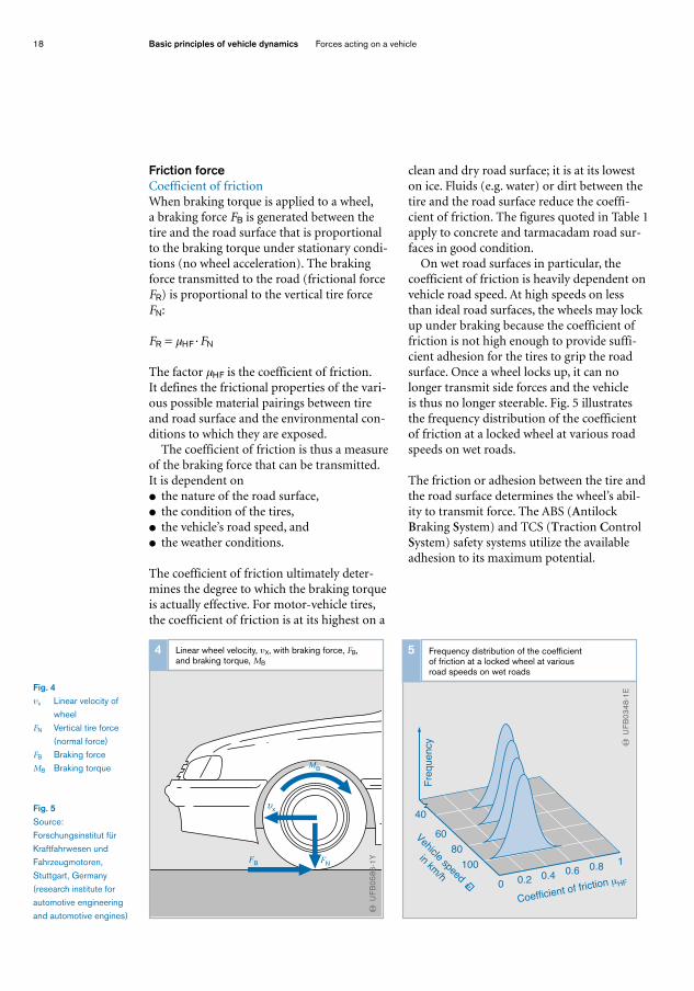
Friction forceCoefficient of frictionWhen braking torque is applied to a wheel, a braking force FB is generated between thetire and the road surface that is proportionalto the braking torque under stationary condi-tions (no wheel acceleration). The brakingforce transmitted to the road (frictional forceFR) is proportional to the vertical tire forceFN:
FR = µHF ·FN
The factor µHF is the coefficient of friction. It defines the frictional properties of the vari-ous possible material pairings between tireand road surface and the environmental con-ditions to which they are exposed. The coefficient of friction is thus a measure
of the braking force that can be transmitted.It is dependent on� the nature of the road surface,� the condition of the tires,� the vehicle’s road speed, and� the weather conditions.
The coefficient of friction ultimately deter-mines the degree to which the braking torqueis actually effective. For motor-vehicle tires,the coefficient of friction is at its highest on a
clean and dry road surface; it is at its loweston ice. Fluids (e.g. water) or dirt between thetire and the road surface reduce the coeffi-cient of friction. The figures quoted in Table 1apply to concrete and tarmacadam road sur-faces in good condition.On wet road surfaces in particular, the
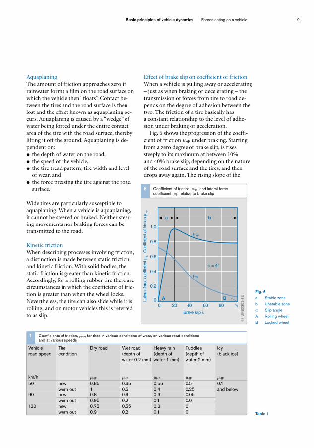
coefficient of friction is heavily dependent onvehicle road speed. At high speeds on lessthan ideal road surfaces, the wheels may lockup under braking because the coefficient offriction is not high enough to provide suffi-cient adhesion for the tires to grip the roadsurface. Once a wheel locks up, it can nolonger transmit side forces and the vehicle is thus no longer steerable. Fig. 5 illustratesthe frequency distribution of the coefficientof friction at a locked wheel at various roadspeeds on wet roads.
The friction or adhesion between the tire andthe road surface determines the wheel’s abil-ity to transmit force. The ABS (AntilockBraking System) and TCS (Traction ControlSystem) safety systems utilize the availableadhesion to its maximum potential.
18 Basic principles of vehicle dynamics Forces acting on a vehicle
Fig. 4υx Linear velocity of
wheelFN Vertical tire force
(normal force)FB Braking forceMB Braking torque
Fig. 5Source:Forschungsinstitut fürKraftfahrwesen undFahrzeugmotoren,Stuttgart, Germany (research institute for automotive engineeringand automotive engines)
x
MB
FNFB
υ
Linear wheel velocity, υX, with braking force, FB, and braking torque, MB
4
æUFB
0586
-1Y
0 0.2 0.40.6 0.8
1100
80
60
40
Coefficient of friction µHF
Vehicle speed
in km/h
υ
Fre
quency
Frequency distribution of the coefficient of friction at a locked wheel at various road speeds on wet roads
5
æUFB
0348
-1E
AquaplaningThe amount of friction approaches zero ifrainwater forms a film on the road surface onwhich the vehicle then “floats”. Contact be-tween the tires and the road surface is thenlost and the effect known as aquaplaning oc-curs. Aquaplaning is caused by a “wedge” ofwater being forced under the entire contactarea of the tire with the road surface, therebylifting it off the ground. Aquaplaning is de-pendent on:� the depth of water on the road,� the speed of the vehicle,� the tire tread pattern, tire width and levelof wear, and
� the force pressing the tire against the roadsurface.
Wide tires are particularly susceptible toaquaplaning. When a vehicle is aquaplaning,it cannot be steered or braked. Neither steer-ing movements nor braking forces can betransmitted to the road.
Kinetic frictionWhen describing processes involving friction,a distinction is made between static frictionand kinetic friction. With solid bodies, thestatic friction is greater than kinetic friction.Accordingly, for a rolling rubber tire there arecircumstances in which the coefficient of fric-tion is greater than when the wheel locks.Nevertheless, the tire can also slide while it isrolling, and on motor vehicles this is referredto as slip.
Effect of brake slip on coefficient of frictionWhen a vehicle is pulling away or accelerating– just as when braking or decelerating – thetransmission of forces from tire to road de-pends on the degree of adhesion between thetwo. The friction of a tire basically has a constant relationship to the level of adhe-sion under braking or acceleration.Fig. 6 shows the progression of the coeffi-
cient of friction µHF under braking. Startingfrom a zero degree of brake slip, is risessteeply to its maximum at between 10% and 40% brake slip, depending on the natureof the road surface and the tires, and thendrops away again. The rising slope of the
Basic principles of vehicle dynamics Forces acting on a vehicle 19
Fig. 6a Stable zoneb Unstable zoneα Slip angleA Rolling wheelB Locked wheel
Table 1
0 20 6040 %80
0
0.2
0.4
0.6
0.8
1.0
a b
Brake slip λ
Late
ral-fo
rce c
oeffic
ient µ
SC
oeffic
ient of fric
tion µ
HF
µHF
µS
α = 4°
BA
Coefficient of friction, µHF, and lateral-force coefficient, µS, relative to brake slip
6
æUFB
0352
-1E
Vehicle Tire Dry road Wet road Heavy rain Puddles Icyroad speed condition (depth of (depth of (depth of (black ice)
water 0.2 mm) water 1 mm) water 2 mm)
km/h µHF µHF µHF µHF µHF
50 new 0.85 0.65 0.55 0.5 0.1worn out 1 0.5 0.4 0.25 and below
90 new 0.8 0.6 0.3 0.05worn out 0.95 0.2 0.1 0.0
130 new 0.75 0.55 0.2 0worn out 0.9 0.2 0.1 0
Coefficients of friction, µHF, for tires in various conditions of wear, on various road conditions and at various speeds
1

curve represents the “stable zone” (partial-braking zone), while the falling slope is the“unstable zone”.
Most braking operations involve minimal lev-els of slip and take place within the stablezone so that an increase in the degree of slipsimultaneously produces an increase in theusable adhesion. In the unstable zone, an increase in the amount of slip generally pro-duces a reduction in the level of adhesion.When braking in such situations, the wheelcan lock up within a fraction of a second, andunder acceleration the excess power-trans-mission torque rapidly increases the wheel’sspeed of rotation causing it to spin.
When a vehicle is traveling in a straight line,ABS and TCS prevent it entering the unstablezone when braking or accelerating.
Sideways forcesIf a lateral force acts on a rolling wheel, thecenter of the wheel moves sideways. The ratiobetween the lateral velocity and the velocityalong the longitudinal axis is referred to as“lateral slip”. The angle between the resultingvelocity, υα, and the forward velocity, υx, iscalled the “lateral slip angle α” (Fig. 7). Theside-slip angle, γ, is the angle between the ve-hicle’s direction of travel and its longitudinalaxis. The side-slip angle encountered at highrates of lateral acceleration is regarded as anindex of controllability, in other words the vehicle’s response to driver input.
Under steady-state conditions (when thewheel is not being accelerated), the lateralforce FS acting on the center of the wheel is inequilibrium with the lateral force applied tothe wheel by the road surface. The relation-ship between the lateral force acting throughthe center of the wheel and the wheel contactforce FN is called the “lateral-force coefficientµS”.
20 Basic principles of vehicle dynamics Forces acting on a vehicle
Fig. 7υα Velocity in lateral
slip directionυx Velocity along
longitudinal axisFS, Fy Lateral forceα Slip angle
Fig. 8FN Vertical tire force
(normal force)FS Lateral force
α α
FS FY
m
υ
xυ
Lateral slip angle, α, and the effect of lateral force, FS,(overhead view)
7
æUFB
0589
-1Y
FS
FS
FN
Position of tire contact area relative to wheel in aright-hand bend showing lateral force, FS, (front view)
8
æUFB
0590
-1Y

There is a nonlinear relationship between the slip angle α and the lateral-force coeffi-cient µS that can be described by a lateral slip curve. In contrast with the coefficient of friction µHF that occurs under accelerationand braking, the lateral-force coefficient µS isheavily dependent on the wheel contact forceFN. This characteristic is of particular interestto vehicle manufacturers when designing sus-pension systems so that handling characteris-tics can be enhanced by stabilizers.
With a strong lateral force, FS, the tire contactarea (footprint) shifts significantly relative tothe wheel (Fig. 8). This retards the buildup of the lateral force. This phenomenon greatlyaffects the transitional response (behavior dur-ing transition from one dynamic state to another) of vehicles under steering.
Effect of brake slip on lateral forcesWhen a vehicle is cornering, the centrifugalforce acting outwards at the center of gravitymust be held in equilibrium by lateral forceson all the wheels in order for the vehicle to beable to follow the curve of the road. However, lateral forces can only be gener-
ated if the tires deform flexibly sideways so that the direction of movement of thewheel’s center of gravity at the velocity, υα, diverges from the wheel center plane “m” by the lateral slip angle, α (Fig. 7).
Fig. 6 shows the lateral-force coefficient, µS,as a function of brake slip at a lateral slip an-gle of 4°. The lateral-force coefficient is at itshighest when the brake slip is zero. As brakeslip increases, the lateral-force coefficient de-clines gradually at first and then increasinglyrapidly until it reaches its lowest point whenthe wheel locks up. That minimum figure oc-curs as a result of the lateral slip angle position of the locked wheel, which at thatpoint provides no lateral force whatsoever.
Friction – tire slip – vertical tire forceThe friction of a tire depends largely on thedegree of slip. The vertical tire force plays asubordinate role, there being a roughly linearrelationship between braking force and verti-cal tire force at a constant level of slip.
The friction, however, is also dependent onthe tire’s lateral slip angle. Thus the brakingand motive force reduces as the lateral slideangle is increased at a constant level of tireslip. Conversely, if the braking and motiveforce remains constant while the lateral slipangle is increased, the degree of tire slip increases.
Basic principles of vehicle dynamics Forces acting on a vehicle 21

Dynamics of linear motionIf the rim of a wheel is subjected both to a lat-eral force and braking torque, the road surfacereacts to this by exerting a lateral force and abraking force on the tire. Accordingly, up to aspecific limit determined by physical parame-ters, all forces acting on the rotating wheel arecounterbalanced by equal and opposite forcesfrom the road surface. Beyond that limit, however, the forces are
no longer in equilibrium and the vehicle’shandling becomes unstable.
Total resistance to motionThe total resistance to vehicle motion, FG, is the sum of the rolling resistance, aerody-namic drag and climbing resistance (Fig. 1).In order to overcome that total resistance, a sufficient amount of motive force has to be applied to the driven wheels. The greaterthe engine torque, the higher the transmis-sion ratio between the engine and the drivenwheels and the smaller the power lossthrough the drivetrain (efficiency η is approx.0.88...0.92 with engines mounted in line, and approx. 0.91...0.95 with trans-
versely mounted engines), the greater is themotive force available at the driven wheels. A proportion of the motive force is re-
quired to overcome the total resistance tomotion. It is adapted to suit the substantialincrease in motion resistance on uphill gradi-ents by the use of a choice of lower gearingratios (multi-speed transmission). If there is a “surplus” of power because the motiveforce is greater than the resistance to motion,the vehicle will accelerate. If the overall resis-tance to motion is greater, the vehicle will de-celerate.
Rolling resistance when traveling in a straight line Rolling resistance is produced by deformationprocesses which occur where the tire is incontact with the road. It is the product ofweight and rolling resistance coefficient andincreases with a smaller wheel diameter andthe greater the degree of deformation of thetire, e.g. if the tire is under-inflated. However,it also increases as the weight on the wheeland the velocity increases. Furthermore, itvaries according to type of road surface – onasphalt, for example, it is only around 25% ofwhat it is on a dirt track.
22 Basic principles of vehicle dynamics Dynamics of linear motion
Fig. 1FL Aerodynamic dragFRo Rolling resistanceFSt Climbing resistanceFG Total resistance
to motionG Weightα Incline angle/
gradient angleS Center of gravity
Table 1Table 2
S
G
α
FL
FSt
FRo
12
FRo
12
Total resistance to motion, FG1
æUA
F004
6-1Y
FG = FL + FSt + FRo
Convertible with top down 0.5 ...0.7Box-type 0.5 ...0.6Conventional saloon 1) 0.4 ...0.55Wedge shape 0.3 ...0.4Aerodynamic fairings 0.2 ...0.25Tear-drop 0.15 ...0.21) “Three-box” design
Vehicle body shape cW
Examples of drag coefficient, cW, for cars
1
Standard tractor unit– without fairings ≥ 0.64– with some fairings 0.54 ...0.63– with all fairings ≤ 0.53
Examples of drag coefficient, cW, for commercial vehicles
2
Vehicle body shape cW
Rolling resistance when cornering When cornering, the rolling resistance isincreased by an extra component, corneringresistance, the coefficient of which is depen-dent on vehicle speed, the radius of the bendbeing negotiated, suspension characteristics,type of tires, tire pressure and lateral-slipcharacteristics.
Aerodynamic dragThe aerodynamic drag FL is calculated fromthe air density ρ, the drag coefficient cW
(dependent on the vehicle body shape, Tables1 and 2), vehicle’s frontal cross-sectional areaA and the driving speed υ (taking account ofthe headwind speed).
FL = cW · A · υ2 · ρ/2
Climbing resistanceClimbing resistance, FSt (if positive), or gravi-tational pull (if negative) is the product of theweight of the vehicle, G, and the angle of up-hill or downhill gradient, α.
FSt = G · sin α
Acceleration and deceleration
Steady acceleration or deceleration in astraight line occurs when the rate of accelera-tion (or deceleration) is constant. The dis-tance required for deceleration is of greatersignificance than that required for accelera-tion because braking distance has directimplications in terms of vehicle and roadsafety.
The braking distance is dependent on a num-ber of factors including� Vehicle speed: at a constant rate of deceler-
ation, braking distance increases quadrati-cally relative to speed.
� Vehicle load: extra weight makes brakingdistances longer.
� Road conditions: wet roads offer lessadhesion between road surface and tiresand therefore result in longer brakingdistances.
� Tire condition: insufficient tread depth in-creases braking distances, particularly onwet road surfaces.
� Condition of brakes: oil on the brake pads/shoes, for example, reduces the friction be-tween the pads/shoes and the disk/drum.The lower braking force thus availableresults in longer braking distances.
� Fading: The braking power also diminishesdue to the brake components overheating.
The greatest rates of acceleration or decelera-tion are reached at the point when the motiveor braking force is at the highest level possiblewithout the tires starting to lose grip (maxi-mum traction).
The rates actually achievable under realconditions, however, are always slightly lowerbecause the vehicle’s wheels are not all at the point of maximum adhesion at pre-cisely the same moment. Electronic traction,braking and vehicle-handling control systems(TCS, ABS and ESP) are active around thepoint of maximum force transmission.
Basic principles of vehicle dynamics Dynamics of linear motion 2

Dynamics of lateral motion
Response to crosswinds
Strong crosswinds can move a vehicle offcourse, especially if it is traveling at a highspeed and its shape and dimensions present alarge surface area for the wind to catch (Fig.1). Sudden crosswind gusts such as may beencountered when exiting a road cutting cancause substantial sideways movement (yaw)of high-sided vehicles. This happens tooquickly for the driver to react and may provoke incorrect driver re-sponse.
When a vehicle is driving through a cross-wind, the wind force, FW, produces a lateralcomponent in addition to the longitudinalaerodynamic drag, FL. Although its effect isdistributed across the entire body surface,it may be thought of as a single force, the lat-eral wind force, FSW, acting at a single pointof action “D”. The actual location of the pointof action is determined by the vehicle’s bodyshape and angle of incidence α of the wind.
The point of action is generally in the front half of the vehicle. On conventionallyshaped saloon cars (“three-box” design) it is largely static and is closer to the center of the vehicle than on vehicles with a morestreamlined body shape (sloping back), whereit can move according to the angle of incidence of the wind.
The position of the center of gravity, S, onthe other hand depends on the size and dis-tribution of the vehicle load. In view of thesevariable factors, therefore, in order to arriveat a general representation of the effect of acrosswind (that is not affected by the relativeposition of the wheels and suspension to thebody), a reference point 0 on the center lineof the vehicle at the front is adopted.
When specifying lateral wind force at a refer-ence point other than the true point ofaction, the turning force of the crosswindaround the point of action, that is the yawmoment, MZ, must also be considered. Thecrosswind force is resisted by the lateral cor-nering forces at the wheels. The degree of lat-eral cornering force which a pneumatic tirecan provide depends on various factors in ad-dition to lateral slip angle and wheel load,such as tire design and size, tire pressure andthe amount of grip afforded by the road surface.
A vehicle will have good directional stabilitycharacteristics in a crosswind if the point ofaction is close to the vehicle’s center of grav-ity. Vehicles that tend to oversteer will deviateless from their course in a crosswind if thepoint of action is forward of the center ofgravity. The best position for the point of ac-tion on vehicles with a tendency to understeeris slightly behind the center of gravity.
2 Basic principles of vehicle dynamics Dynamics of lateral motion
Fig. 1
D Point of action
O Reference point
S Center of gravity
FW Wind force
FL Aerodynamic drag
FSW Lateral wind force
MZ Yaw moment
α Angle of incidence
l Vehicle length
d Distance of point
of action, D, from
reference point, O
FS and MZ acting at O
corresponds to FS acting
at D (in aerodynamics
it is normal to refer to
dimensionless coeffi-
cients instead of forces)
S
O
D
d
l
FSW
+MZ
FSW
FSW
FL
FW
α
Vehicle in crosswind1
æUA
F0
047-1
Y

Understeer and oversteer
Cornering forces between a rubber-tiredwheel and the road can only be generatedwhen the wheel is rotating at an angle to itsplane. A lateral slip angle must therefore bepresent. A vehicle is said to understeer when,as lateral acceleration increases, the lateral slipangle at the front axle increases more than itdoes at the rear axle. The opposite is true of avehicle which oversteers (Fig. 2).
For safety reasons, vehicles are designed toslightly understeer. As a result of drive slip,however, a front-wheel drive vehicle canquickly change to sharply understeer or a rear-wheel drive vehicle to oversteer.
Centrifugal force while cornering
Centrifugal force, Fcf, acts at the center of gravity, S, (Fig. 3). Its effect depends on a number of factors such as� the radius of the bend,� the speed of the vehicle,� the height of the vehicle’s center of gravity,� the mass of the vehicle,� the track of the vehicle,� the frictional characteristics of the tire and
road surface (tire condition, type of surface, weather conditions), and
� the load distribution in the vehicle.
Potentially hazardous situations will occurwhen cornering if the centrifugal forcereaches a point where it threatens to over-come the lateral forces at the wheels and the vehicle cannot be held on its intendedcourse. This effect can be partially counter-acted by positive camber or banked corners.
If the vehicle slips at the front wheel, it un-dersteers; if it slips at the wheel axle, it over-steers. In both cases the Electronic StabilityProgram (ESP) detects an undesirable rota-tion about the vertical axle. By active inter-vention in the form of selective braking of in-dividual wheels, it is then able to correct theimbalance.
Basic principles of vehicle dynamics Dynamics of lateral motion 2
Fig. 2
a Understeer
b Oversteer
αV Front lateral
slip angle
αH Rear lateral
slip angle
δ Steering angle
� Side-slip angle
FS Lateral force
MG Yaw moment
Fig. 3
Fcf Centrifugal force
υF Vehicle speed
FS Lateral force at
individual wheels
rK Radius of bend
S Center of gravity
ba
S�G
S
�G
�S
�S
αH
αH
αv
αv
β β
�S
�S
δδ
Vehicle oversteer and understeer2
æUA
F0
073
-1Y
FS
Fcf
F
rK
S
υ
Centrifugal force while cornering3
æUA
F0
04
8-1
Y

Definitions
Braking sequence
As defined in ISO 611, the term “brakingsequence” refers to all operations that takeplace between the point at which operation ofthe (brake) actuation device begins and thepoint at which braking ends (when the brakeis released or the vehicle is at a standstill).
Variable braking A type of braking system which allows thedriver at any time to increase or reduce thebraking force to a sufficiently precise degreeby operating the actuation device within itsnormal effective range.
If operating the actuation device in a par-ticular manner increases the braking force,then the opposite action must reverse the ef-fect and reduce the braking force.
Braking-system hysteresisBraking system hysteresis is the difference be-tween the actuating forces when the brake isapplied and released at a constant brakingtorque.
Brake hysteresis Brake hysteresis is the difference between theapplication forces when the brake is actuatedand released at a constant braking torque.
Forces and torques
Actuating forceThe actuating force, FC, is the force that isapplied to the actuation device.
Application forceOn a friction brake, the application force isthe total force exerted on the brake-padmount, together with attached friction mater-ial, in order to generate the friction requiredfor the braking force.
Total braking forceThe total braking force, Ff, is the sum total ofbraking forces at each of the wheels that areproduced by the effect of the braking systemand which oppose the vehicle’s motion or itstendency to move.
Braking torqueThe braking torque is the product of the fric-tional forces generated in the brake by the ap-plication forces and the distance of the point ofaction of those forces from the axis of rota-tion of the wheel.
Braking-force distributionThe braking-force distribution indicates interms of percentage share how the total brak-ing force, Ff, is distributed between the frontand rear wheels, e.g. front wheels 60%, rearwheels 40%.
External brake coefficient, CThe external brake coefficient, C, is the ratio ofthe output torque to the input torque or theoutput force to the input force of a brake.
Internal brake coefficient, C*The internal brake coefficient, C*, is the ratioof the total tangential force acting at the effec-tive radius of a brake to the application force,FS.
Typical values: for drum brakes, values ofup to C* = 10 may be obtained, for disc brakesC* ≈ 1.
Time periods
The braking sequence is characterised by anumber of time periods which are definedwith reference to the ideal curves shown inFigure 1.
Period of movement of actuation device The period of movement of the actuation de-vice is the time from the point at which forceis first applied to the actuation device (t0), tothe point at which it reaches its final position(t3) as determined by the actuating force orthe actuation travel. The same applies by anal-ogy to the release of the brakes.
2 Basic principles of vehicle dynamics Definitions

Response timeThe response time, ta, is the time that elapsesfrom the point at which force is first appliedto the actuation device to the point at whichbraking force is first produced (pressure gen-erated in the brake lines) (t1 – t0).
Pressure build-up timeThe pressure build-up time, ts, is the time fromthe point at which braking force is first pro-duced to the point at which the pressure inthe brake lines reaches its highest level (t5 – t1).
Total braking timeThe braking time, tb, is the time that elapsesfrom the point at which force is first appliedto the actuation device to the point at whichbraking force ceases (t7 – t0). If the vehiclecomes to a halt, then the moment at whichthe vehicle is first stationary is the moment atwhich the braking time ends.
Effective braking timeThe effective braking time, tw, is the time thatelapses from the moment at which brakingforce is first produced to the moment atwhich braking force ceases (t7 – t2). If the ve-hicle comes to a halt, then the moment atwhich the vehicle is first stationary is the mo-ment at which the effective braking timeends.
Distances
Braking distanceThe braking distance, s1, is the distance trav-elled by a vehicle during the period of the effective braking time (t7 – t2).
Total braking distanceThe total braking distance s0 is the distancetravelled by a vehicle during the period of thetotal braking time (t7 – t0). That is the dis-tance travelled from the point at which thedriver first applies force to the actuation de-vice to the point at which the vehicle is at astandstill.
Braking deceleration
Momentary deceleration The momentary deceleration, a, is the quotientof the reduction in speed and the elapsed time.a = dυ/dt
Average deceleration over the total brakingdistanceFrom the vehicle speed υ0 at the time t0, theaverage deceleration, ams, over the stoppingdistance, s0, is calculated using the formulaams = υ0
2/2s0
Mean fully developed decelerationThe figure for mean fully developed decelera-tion, amft, represents the average decelerationduring the period in which deceleration is atits fully developed level (t7 – t6).
Braking factorThe braking factor, Z, is the ratio between to-tal braking force, Ff, and total static weight,GS, (vehicle weight) acting on the axle or axlesof the vehicle. That is equivalent to the ratioof braking deceleration, a, to gravitational ac-celeration, g (g = 9.81 m/s2).
Basic principles of vehicle dynamics Definitions 2
Fig. 1
1 Vehicle speed
2 Distance travelled
while braking
3 Vehicle
deceleration
4 Brake-line pressure
(brake pressure)
5 Actuation device
travel
t0 Time at which the
driver first applies
force to actuation
device
t1 Brake-line pressure
(brake pressure)
starts to rise
t2 Vehicle deceleration
begins
t3 Actuation device
has reached
intended position
t4 Intersection of
extended speed
curve sections
t5 Brake-line pressure
has reached
stabilised level
t6 Vehicle deceleration
has reached
stabilised level
t7 Vehicle comes to
a haltTime
t0
s0
amft
0
t1 t2 t4t3 t6t5 t7
Veh
icle
dec
eler
atio
n, b
rake
-line
pre
ssur
eA
ctua
ting
devi
ce tr
avel
Veh
icle
spe
edD
ista
nce
trave
lled
1
3
4
5
2
υ
Vehicle braking sequence to the point of standstill(ideal case)
1
æUF
B0
72
0E

http://www.springer.com/978-3-658-03977-6