Distributed System Using Java 2 Enterprise Edition (J2EE) B.Ramamurthy.
1B.Ramamurthy
Basic Pipelining
B.Ramamurthy
CS506
2B.Ramamurthy
Introduction
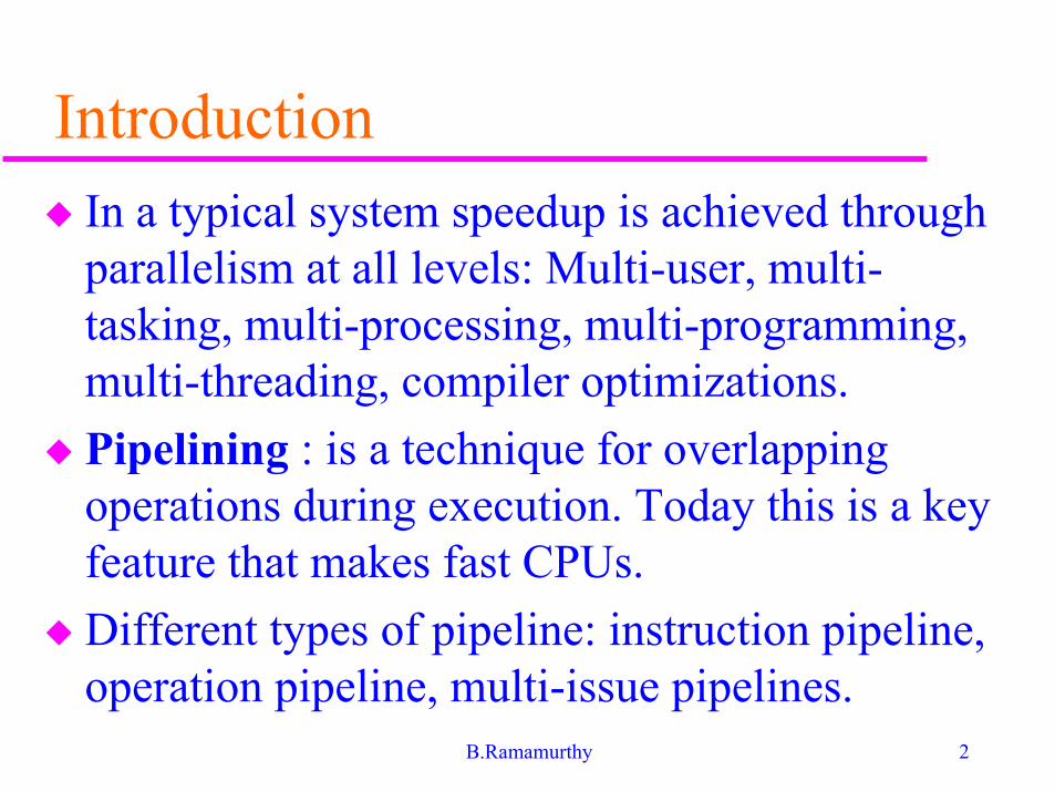
� In a typical system speedup is achieved throughparallelism at all levels: Multi-user, multi-tasking, multi-processing, multi-programming,multi-threading, compiler optimizations.
� Pipelining : is a technique for overlappingoperations during execution. Today this is a keyfeature that makes fast CPUs.
� Different types of pipeline: instruction pipeline,operation pipeline, multi-issue pipelines.

3B.Ramamurthy
Topics to be discussed� What is a pipeline?
� A simple implementation of DLX
� Basic pipeline of DLX
� Performance issues
� Structural hazards
� Data hazards
� Control hazards
� Implementation issues
� Handling multi-cycle operations
� Instruction set design and pipelining
� Example: MIPS pipeline
� Summary

4B.Ramamurthy
What is a pipeline?
� Pipeline is like an automobile assembly line.
� A pipeline has many steps or stages or segments.
� Each stage carries out a different part ofinstruction or operation.
� The stages are connected to form a pipe.
� An inst or operation enters through one end andprogresses thru’ the stages and exit thru’ the otherend.
� Pipelining is an implementation technique thatexploits parallelism among the instructions in asequential instruction stream.
5B.Ramamurthy
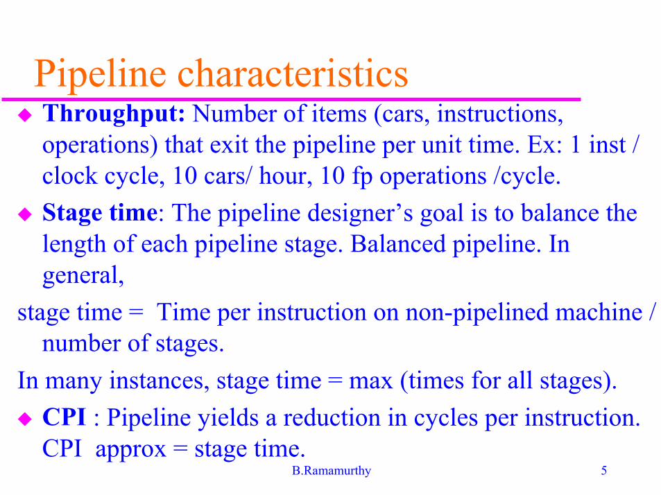
Pipeline characteristics� Throughput: Number of items (cars, instructions,
operations) that exit the pipeline per unit time. Ex: 1 inst /clock cycle, 10 cars/ hour, 10 fp operations /cycle.
� Stage time: The pipeline designer’s goal is to balance thelength of each pipeline stage. Balanced pipeline. Ingeneral,
stage time = Time per instruction on non-pipelined machine /number of stages.
In many instances, stage time = max (times for all stages).
� CPI : Pipeline yields a reduction in cycles per instruction.CPI approx = stage time.
6B.Ramamurthy
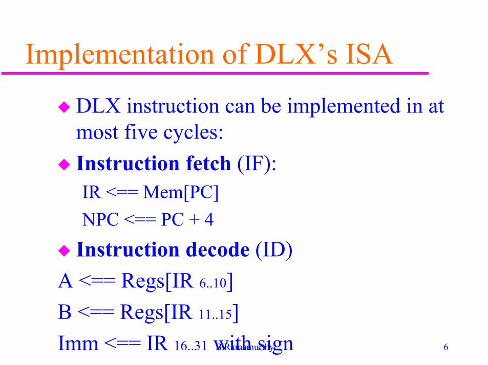
Implementation of DLX’s ISA
� DLX instruction can be implemented in atmost five cycles:
� Instruction fetch (IF):IR <== Mem[PC]
NPC <== PC + 4
� Instruction decode (ID)
A <== Regs[IR 6..10]
B <== Regs[IR 11..15]
Imm <== IR 16..31 with sign
7B.Ramamurthy
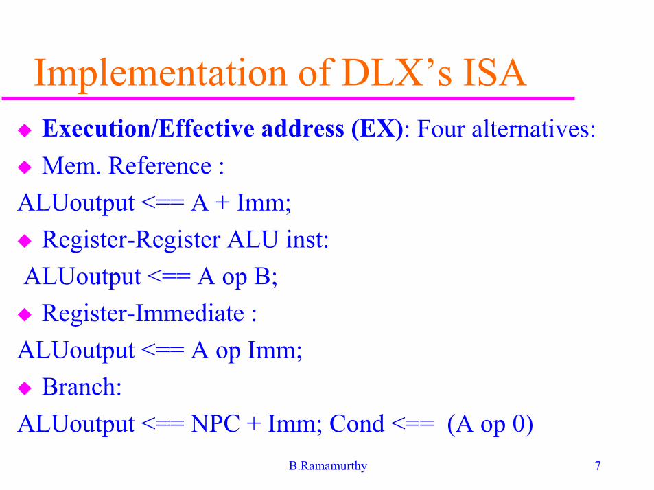
Implementation of DLX’s ISA� Execution/Effective address (EX): Four alternatives:
� Mem. Reference :
ALUoutput <== A + Imm;
� Register-Register ALU inst:
ALUoutput <== A op B;
� Register-Immediate :
ALUoutput <== A op Imm;
� Branch:
ALUoutput <== NPC + Imm; Cond <== (A op 0)
8B.Ramamurthy
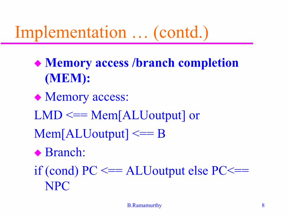
Implementation … (contd.)
� Memory access /branch completion(MEM):
� Memory access:
LMD <== Mem[ALUoutput] or
Mem[ALUoutput] <== B
� Branch:
if (cond) PC <== ALUoutput else PC<==NPC
9B.Ramamurthy
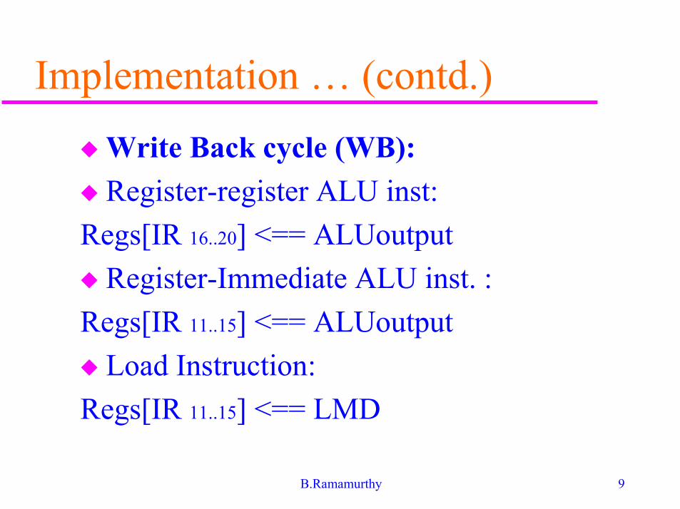
Implementation … (contd.)
� Write Back cycle (WB):
� Register-register ALU inst:
Regs[IR 16..20] <== ALUoutput
� Register-Immediate ALU inst. :
Regs[IR 11..15] <== ALUoutput
� Load Instruction:
Regs[IR 11..15] <== LMD
10B.Ramamurthy
Hardware diagram
� Fig. 3.1 Study and understand thoroughlythe various components.

11B.Ramamurthy
12B.Ramamurthy

13B.Ramamurthy
Timing and control (The missinglinks)
� What’s missing in the RTL description ofDLX given above is the timing and controlinformation:
� For example: (Add R1,R2,R3)
Add.t0: IR <== Mem[PC], NPC <== PC + 4
Add.t1: A <== Regs[IR 6..10], B <== Regs[IR11..15]
Add.t2: ALUoutput <== A op B;
Add.t3: do nothing (idling)
Add.t4: Regs[IR 16..20] <== ALUoutput
14B.Ramamurthy
Timing and control - Branch
Br.t0 : IR <== Mem[PC], NPC <== PC + 4
Br.t1 : A <== Regs[IR 6..10], Imm <== IR 16..31
with sign
Br.t2 : ALUoutput <== NPC + Imm; Cond<== (A op 0)
Br.t3 : if (cond) PC <== ALUoutput elsePC<== NPC

15B.Ramamurthy
Basic pipeline of DLX
� Five stages: IF, ID, EX, MEM, WB
� On each clock cycle an instruction isfetched and begins its five cycle execution.
� Performance is up to five times that of amachine that is non-pipelined.
� What do we need in the implementation ofthe data path to support pipelining?
16B.Ramamurthy
Pipelining the DLX datapath1) Separate instruction and data caches eliminating a conflict
that would arise between instruction fetch and data memoryaccess. This is shown in the data path we studied earlier.This design avoids resource conflict.
2) We need to avoid register file access conflict: it is accessedonce during ID and another time during WB stage.
3) Update PC every cycle. So mux from memory access stage isto be moved to IF stage.
4) All operations in one stage should complete within a clockcycle.
5) Values passed from one stage to the next must be placed inbuffers/latches (I use buffers instead of registers to avoidconfusion with regular registers).
17B.Ramamurthy
Pipelining the DLX datapath� How do arrive at the above list of requirements?
Examine what happens in each pipeline stage dependingon the instruction type. Make a list of all thepossibilities.
� RTL statements of the events on every stage of the DLXpipeline is given in Fig.3.5.
� To control this pipeline, we only need to determine howto set the control on the four multiplexers (mux)
– The first one inputs to PC. Lets call it MUX1.
– The next two the input to ALU: MUX2, MUX3
– The fourth one input to register file: MUX4
18B.Ramamurthy
Controlling the pipeline
� Lets refer to interface between stages IFand ID, IF/ID and the other interfacesbetween stages ID/EX, EX/MEM, andMEM/WB.
� MUX1: is controlled by the conditionchecking done at EX/MEM. Based on thiscondition EX/MEM.cond, the MUX1selects the current PC or the branch targetas the instruction address.
19B.Ramamurthy
Controlling the pipeline (contd.)
� MUX2 and MUX3 are controlled by the type ofinstruction. MUX2 is set by whether theinstruction is a branch or not. MUX3 is set bywhether the instruction is Register-Register ALUoperation or any other operation.
� MUX4: is controlled by whether the instruction inthe WB stage is a load or an ALU operation.
� In addition there is one MUX which chooses thecorrect portion of the IR in the MEM/WB bufferto specify the register destination field.
20B.Ramamurthy
Pipeline performance - Example1� General: 40% ALU, 20% branch, 40%
memory.
� Design1: Non- pipelined. 10ns clock cycles.ALU operations and branches take 4 cycles,memory operations take 5 cycles..In otherwords, ALU operations and branches take4*10 = 40 ns time.
� Design 2: Pipelined. Clock skew and setupadd 1 ns overhead to clock cycle.
� What is the speedup?
21B.Ramamurthy
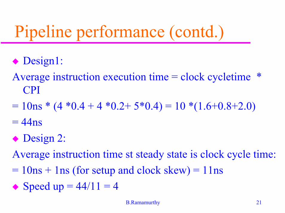
Pipeline performance (contd.)
� Design1:
Average instruction execution time = clock cycletime *CPI
= 10ns * (4 *0.4 + 4 *0.2+ 5*0.4) = 10 *(1.6+0.8+2.0)
= 44ns
� Design 2:
Average instruction time st steady state is clock cycle time:
= 10ns + 1ns (for setup and clock skew) = 11ns
� Speed up = 44/11 = 4
22B.Ramamurthy
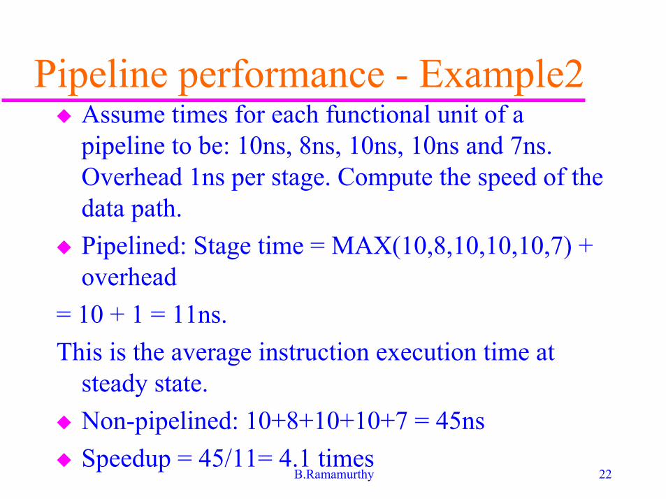
Pipeline performance - Example2� Assume times for each functional unit of a
pipeline to be: 10ns, 8ns, 10ns, 10ns and 7ns.Overhead 1ns per stage. Compute the speed of thedata path.
� Pipelined: Stage time = MAX(10,8,10,10,10,7) +overhead
= 10 + 1 = 11ns.
This is the average instruction execution time atsteady state.
� Non-pipelined: 10+8+10+10+7 = 45ns
� Speedup = 45/11= 4.1 times
23B.Ramamurthy
Pipeline hazards� Hazards reduce the performance from the
ideal speedup gained by pipelines:
� Structural hazard: Resource conflict.Hardware cannot support all possiblecombinations of instructions insimultaneous overlapped execution.
� Data hazard: When an instruction dependson the results of the previous instruction.
� Control hazard: Due to branches and otherinstructions that affect the PC.
24B.Ramamurthy
Pipeline stalls� A stall is the delay in cycles caused due to
any of the hazards mentioned above.
� Speedup :
1/(1+pipeline stall per instruction)* Numberof stages
� So what is the speed up for an ideal pipelinewith no stalls?
� Number of cycles needed to initially fill upthe pipeline could be included incomputation of average stall per instruction.
25B.Ramamurthy
Structural hazards� When more than one instruction in the pipeline
needs to access a resource, the datapath is said tohave a structural hazard.
� Examples of resources: register file, memory,ALU.
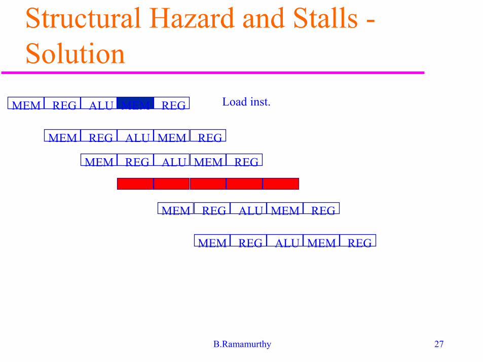
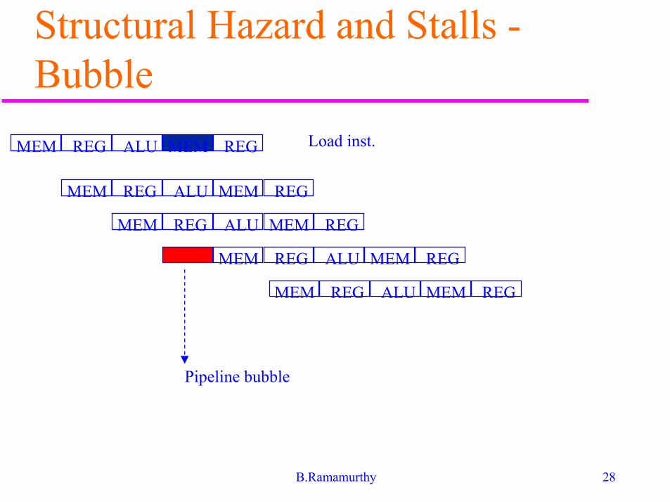
� Solution: Stall the pipeline for one clock cyclewhen the conflict is detected. This results in apipeline bubble.
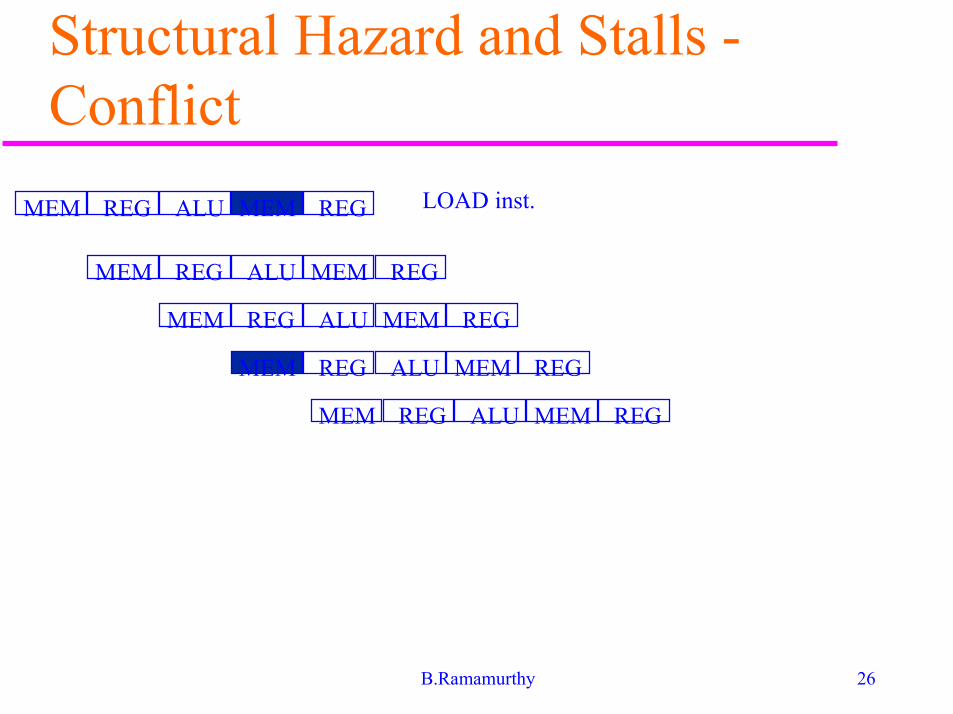
� See Fig.3.6, 3.7 that illustrate the memory accessconflict and how it is resolved by stalling aninstruction. Problem: one memory port.
26B.Ramamurthy
Structural Hazard and Stalls -Conflict
MEM REG ALU MEM REG
MEM REG ALU MEM REG
MEM REG ALU MEM REG
MEM REG ALU MEM REG
MEM REG ALU MEM REG
LOAD inst.
27B.Ramamurthy
Structural Hazard and Stalls -Solution
MEM REG ALU MEM REG
MEM REG ALU MEM REG
MEM REG ALU MEM REG
MEM REG ALU MEM REG
MEM REG ALU MEM REG
Load inst.
28B.Ramamurthy
Structural Hazard and Stalls -Bubble
MEM REG ALU MEM REG
MEM REG ALU MEM REG
MEM REG ALU MEM REG
MEM REG ALU MEM REG
Load inst.
MEM REG ALU MEM REG
Pipeline bubble
29B.Ramamurthy
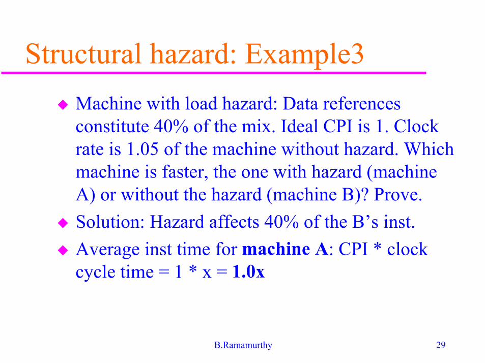
Structural hazard: Example3
� Machine with load hazard: Data referencesconstitute 40% of the mix. Ideal CPI is 1. Clockrate is 1.05 of the machine without hazard. Whichmachine is faster, the one with hazard (machineA) or without the hazard (machine B)? Prove.
� Solution: Hazard affects 40% of the B’s inst.
� Average inst time for machine A: CPI * clockcycle time = 1 * x = 1.0x
30B.Ramamurthy
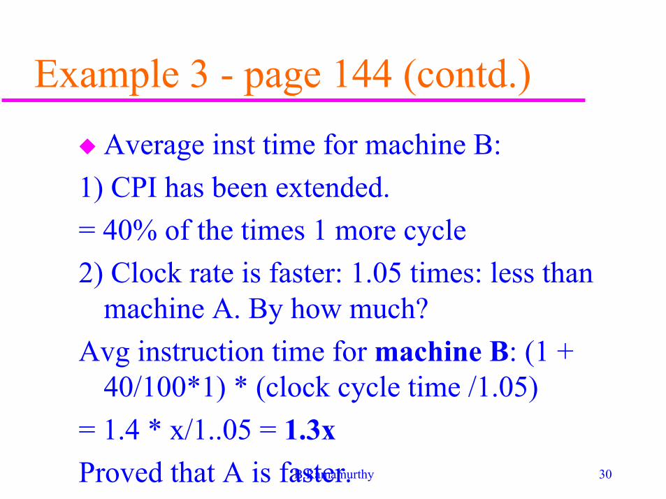
Example 3 - page 144 (contd.)
� Average inst time for machine B:
1) CPI has been extended.
= 40% of the times 1 more cycle
2) Clock rate is faster: 1.05 times: less thanmachine A. By how much?
Avg instruction time for machine B: (1 +40/100*1) * (clock cycle time /1.05)
= 1.4 * x/1..05 = 1.3x
Proved that A is faster.
31B.Ramamurthy
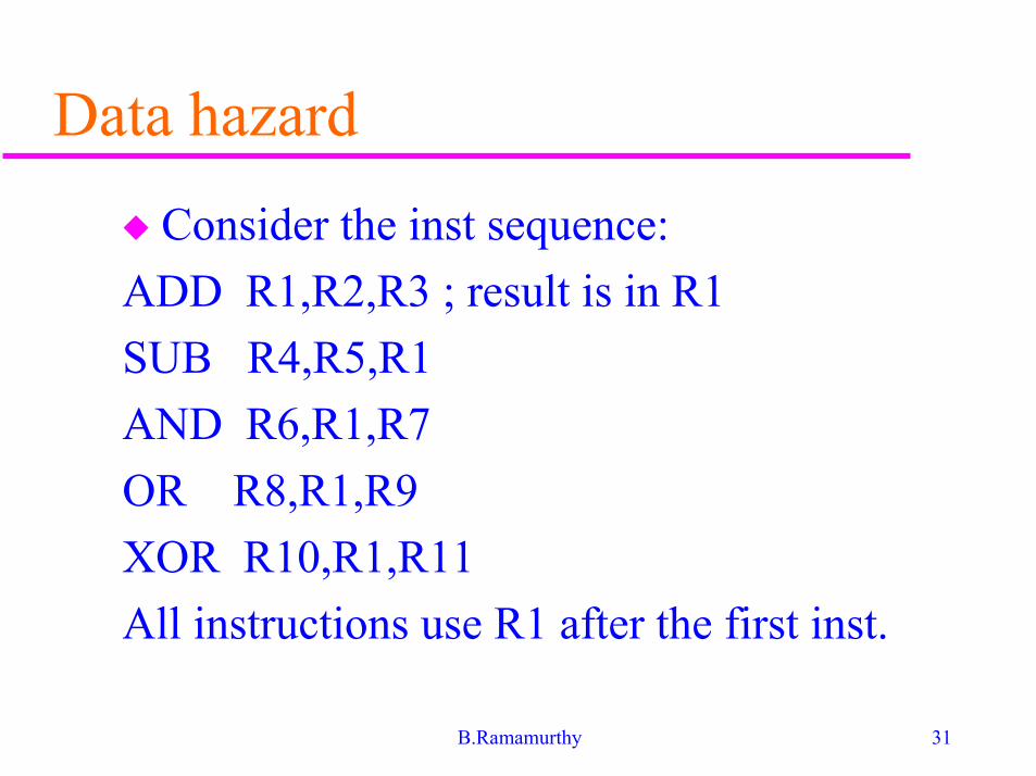
Data hazard
� Consider the inst sequence:
ADD R1,R2,R3 ; result is in R1
SUB R4,R5,R1
AND R6,R1,R7
OR R8,R1,R9
XOR R10,R1,R11
All instructions use R1 after the first inst.

32B.Ramamurthy
Data hazard - Time-stagediagram
MEM REG ALU MEM REG
MEM REG ALU MEM REG
MEM REG ALU MEM REG
MEM REG ALU MEM REG
MEM REG ALU MEM REG
33B.Ramamurthy
Data hazard - solution� Usually solved by data or register forwarding
(bypassing or short-circuiting).
� How? The data selected is not really used in IDbut in the next stage: ALU.
� Forwarding works as follows:
� ALU result from EX/MEM buffer is always fedback to ALU input latches.
� If the forwarding hardware detects that its sourceoperand has a new value, the logic selects thenewer result than the value read from the registerfile.
34B.Ramamurthy
Data hazard - solution (contd.)
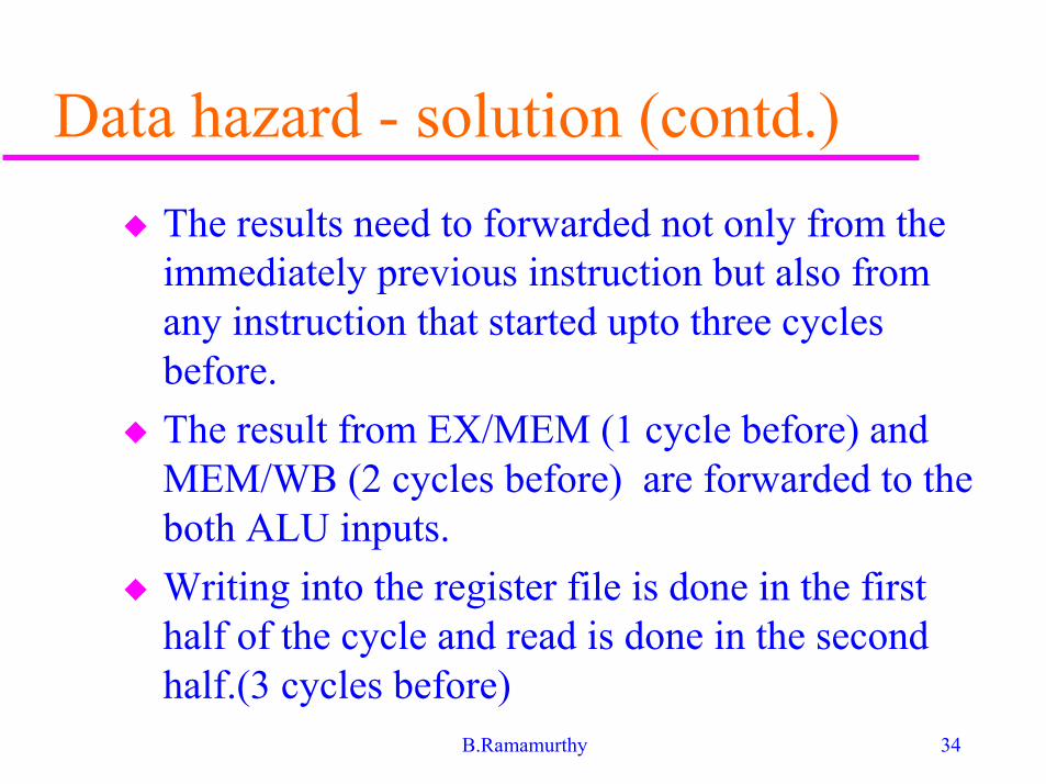
� The results need to forwarded not only from theimmediately previous instruction but also fromany instruction that started upto three cyclesbefore.
� The result from EX/MEM (1 cycle before) andMEM/WB (2 cycles before) are forwarded to theboth ALU inputs.
� Writing into the register file is done in the firsthalf of the cycle and read is done in the secondhalf.(3 cycles before)
35B.Ramamurthy
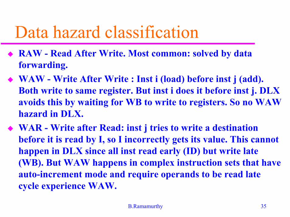
Data hazard classification� RAW - Read After Write. Most common: solved by data
forwarding.
� WAW - Write After Write : Inst i (load) before inst j (add).Both write to same register. But inst i does it before inst j. DLXavoids this by waiting for WB to write to registers. So no WAWhazard in DLX.
� WAR - Write after Read: inst j tries to write a destinationbefore it is read by I, so I incorrectly gets its value. This cannothappen in DLX since all inst read early (ID) but write late(WB). But WAW happens in complex instruction sets that haveauto-increment mode and require operands to be read latecycle experience WAW.
36B.Ramamurthy
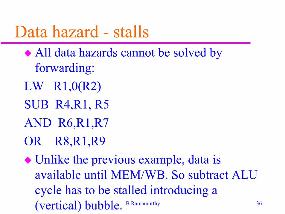
Data hazard - stalls� All data hazards cannot be solved by
forwarding:
LW R1,0(R2)
SUB R4,R1, R5
AND R6,R1,R7
OR R8,R1,R9
� Unlike the previous example, data isavailable until MEM/WB. So subtract ALUcycle has to be stalled introducing a(vertical) bubble.
37B.Ramamurthy
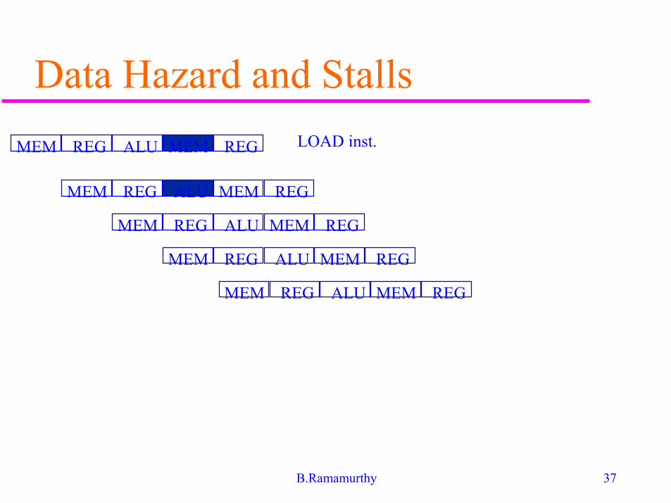
Data Hazard and Stalls
MEM REG ALU MEM REG
MEM REG ALU MEM REG
MEM REG ALU MEM REG
MEM REG ALU MEM REG
MEM REG ALU MEM REG
LOAD inst.
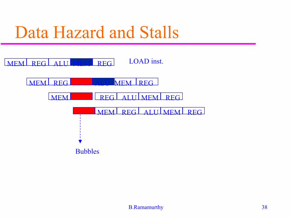
38B.Ramamurthy
Data Hazard and Stalls
MEM REG ALU MEM REG
MEM REG ALU MEM REG
MEM REG ALU MEM REG
MEM REG ALU MEM REG
LOAD inst.
Bubbles
39B.Ramamurthy
Summary
� Concepts in basic pipelining were studiedin details.
� Data hazards and control hazards andmethods for resolving these were alsodiscussed.