Basic Methods of Reading Flow in Hydronic Systems
66
Basic Methods of Reading Flow in Hydronic Systems Scott Fielder National Comfort Institute, Inc. Content and illustrations © NCI, Inc. 2020
Transcript of Basic Methods of Reading Flow in Hydronic Systems

Basic Methods of Reading Flow in Hydronic Systems
Scott FielderNational Comfort Institute, Inc.
Content and illustrations © NCI, Inc. 2020

Basic Methods of Reading Flow in Hydronic Systems
I was fortunate enough to be raised in a company that raised technicians to learn how to balance hydronic systems hand-in-hand with air side systems.
I was taught that the same laws of physics apply to water as they do air.
In fact, my VERY second day in my career, I was at DFW Airport with the owner of my company, hooking up gauges, closing valves and tasting glycol from 12 new pumps and 6 chillers.

And exactly 30 minutes into this endeavor, under strict supervision and
excellent instruction, I promptly got ahead of myself and my supervisor,
and crashed one of the chillers.
The Facilities Manager put his arm around my shoulder and said, “Son, I sure hope that guy is your dad, because if that
chiller doesn’t come back online, you’ll probably be flipping burgers tomorrow.

I learned a couple of valuable lessons:
1. Never close the valve on the suction side of chiller. Or pump.
2. In spite of the in apparent simplicity, hydronic systems can be fragile, easily damaged, and often serve the most expensive equipment on the entire project!

Unlike the Air Side, a technician can not simply put a flow hood on every valve or coil.

That wouldn’t end well...

Unlike the Air Side, a technician can not drill into a pipe to take a hydronic flow traverse reading.

That wouldn’t end well, either.
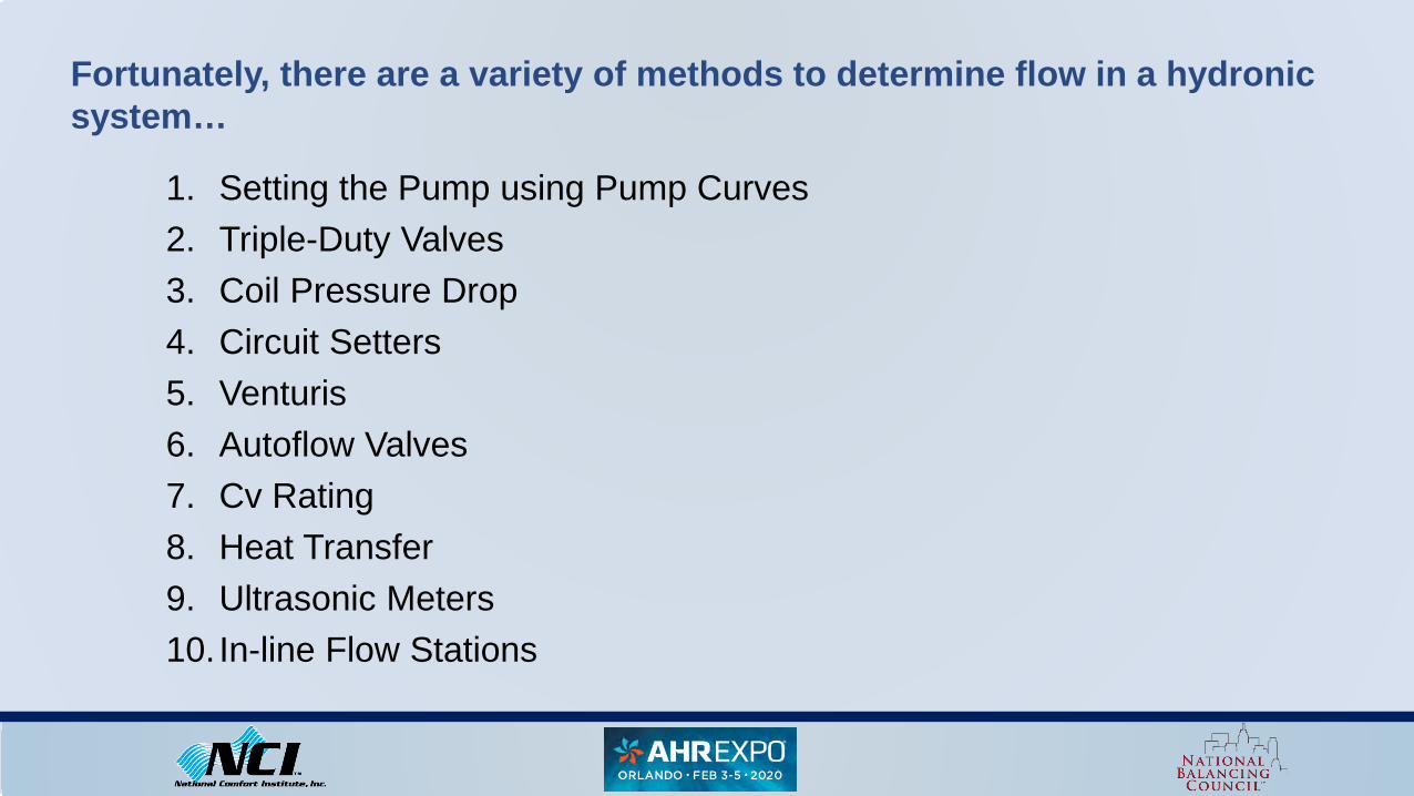
Fortunately, there are a variety of methods to determine flow in a hydronic system…
1. Setting the Pump using Pump Curves2. Triple-Duty Valves3. Coil Pressure Drop4. Circuit Setters5. Venturis6. Autoflow Valves7. Cv Rating8. Heat Transfer9. Ultrasonic Meters10. In-line Flow Stations

Hydronic Flow At Pump
Hydronic Flow At Chiller Hydronic Flow At All Coils
The TAB Professional Triangulates

Hydronic Flow At Pump
Hydronic Flow At Chiller Hydronic Flow At All Coils
The TAB Professional takes multiple readings, with multiple, calibrated instruments.

The TAB Professional must also possess the proper equipment…
1. Hydronic Manometers

The TAB Professional must also possess the proper equipment…
2. Thermometers with Temperature Probes

The TAB Professional must also possess the proper equipment…
3. Temperature Clamps

Now that the TAB Professional is properly equipped, the following information MUST be provided:
1. ALL mechanical drawings2. Schedule of Equipment3. Mechanical Details4. Manufacturers submittals ( to include pump curves, coil data, heat
exchangers, valves, etc.)5. Written confirmation that mechanical, electrical and building automation
contractors are complete6. Written confirmation that system has been flushed and treated

Setting flow at the pump using the pump curve is the primary method of establishing total system flow.
The TAB professional must have the manufacturer’s pump curve in order to accomplish this.
All parties concerned, from the design team to the installer to the TAB professional MUST be aware of particular inaccuracies in this process.

Dead Head @80’ Head
What’s the impeller size?
Data From a Pump Curve

Dead Head @80’ Head
8.8”
Data From a Pump Curve

Valve OpenDP @ 65.5’
What is our Full Open GPM?
Data From a Pump Curve

Valve OpenDP @ 65.5’
123 GPM?
Data From a Pump Curve

Dead Head 80’Valve Open 65.5’
138 GPM?
12% Difference
Second look …Another Technician plots the same data on the same curve
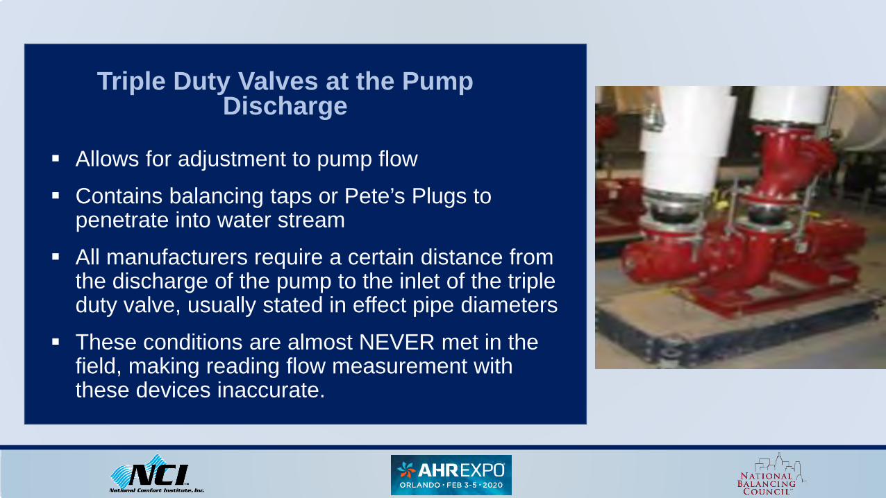
Triple Duty Valves at the Pump Discharge
Allows for adjustment to pump flow Contains balancing taps or Pete’s Plugs to
penetrate into water stream All manufacturers require a certain distance from
the discharge of the pump to the inlet of the triple duty valve, usually stated in effect pipe diameters
These conditions are almost NEVER met in the field, making reading flow measurement with these devices inaccurate.

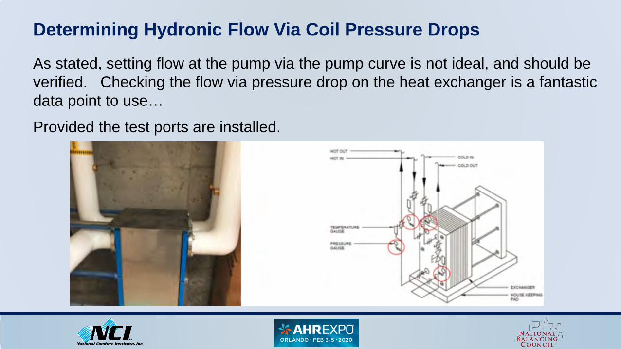
Determining Hydronic Flow Via Coil Pressure Drops
The most common method of determining coil flow is by taking a pressure drop across the coil, between the entering and leaving sides of the coil, consistent with the second affinity law or pump law. Pressure increases at a square rate, or 2:1 ratio of fluid flow
1
212 PD
PDGPMGPM ×=

D
ADA P
PGPMGPM∆∆
×=
Where:
GPMA = Actual GPM
GPMD = Design GPM
ΔPA = Actual Pressure Drop
ΔPD = Design Pressure Drop
Determining Hydronic Flow Via Coil Pressure Drops
Or better expressed as follows:

D
ADA P
PGPMGPM∆∆
×=
33.19.87.GPM A ×=
68.87.GPM A ×=
82.87.GPM A ×=
71.GPM A =
Determining Hydronic Flow Via Coil Pressure Drops
Example:

Determining Hydronic Flow Via Coil Pressure Drops
Can also be used on other pieces of equipment such as the chiller, condenser and heat exchangers.
Again, the manufacturers’ data is required.
Determining Hydronic Flow Via Coil Pressure Drops
As stated, setting flow at the pump via the pump curve is not ideal, and should be verified. Checking the flow via pressure drop on the heat exchanger is a fantastic data point to use…Provided the test ports are installed.

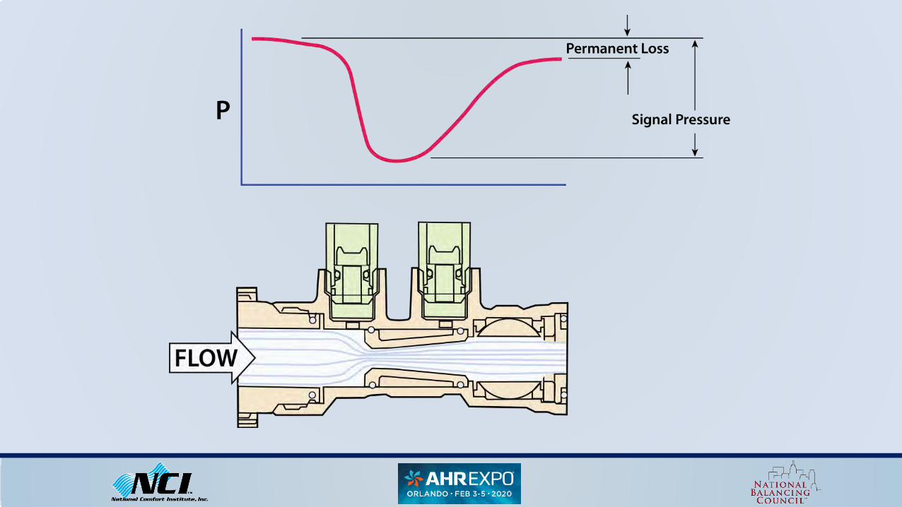
Velocity Head RecoveryChanges in fluid velocity through the valve orifice are as illustrated. Actual pressure drop imposed against the pump (ΔP from C to D) is on the order .7 to .9 of the value as read across the read-out ports A-B. These differences are significant enough to require two different sets of ΔP data to be shown on the Circuit Setter Balance Valve Calculator.

Armstrong Calculator
Circuit Setters

Venturi Valves
What Is A Venturi?
A venturi converts pressure to kinetic energy, then converts it back.
It gets narrow, then widens out gradually so as not to stir up the water too much. As the passage narrows, the pressure goes down.
For a flow meter, we have a connection to the water stream before the passage narrows, and a second port at the narrowest point, sometimes called the “throat”.
The pressure at the throat is lower than the downstream pressure, so the pressure difference we read is higher than the permanent loss that is created.

Circuit Setter Vs. Venturi Valve – Simplest Explanation
In a Circuit Setter, the pressure drop is taken across the valve as it opens and closes.
Flow is determined based upon the pressure drop at a given valve position.
These values are plotted by the manufacturer, and then placed on a chart, wheel or program.
With a venutri, the flow is based upon pressure drop across a FIXED orifice, and flow is regulated upstream or downstream of the pressure drop.

Where:
Cv = Value coefficient
GPM = Water flow rate in gallons per minute
ΔP = Differential pressure (upstream pressure – downstream pressure)
The value coefficient is a number representing the ability of a valve or any component in a hydronic system to flow a fluid.
A Cv value of 1 is the Cv required to flow 1 gpm of water at 60° F, with a ΔP of 1 PSI.
GPM = Cv x √ΔP
Determining GPM via Cv

Using the Cv is great for when no design data is provided,
And the TAB technician is able to obtain a pressure drop across a component.
It is also another way to confirm and double check flow.
GPM = Cv x √ΔP
Determining GPM via Cv

When no design data is provided, and the Cv is not tagged or stamped on equipment, TAB professional can perform an online search.
Years ago, all the way back in aught 3, we’d have to call the mechanical, fax the distributor, and on and on and it could take days to locate the data.
Now that we all carry smart phones, the world is much simpler.
Can any one here tell me what the Cv rating for a B & G 1/2” Model UBY Strainer is?
Some one should have the answer in about 40 seconds.
The class record stands at 13.5 seconds.
Determining GPM via Cv

Determining GPM via Cv

Determining GPM via Cv
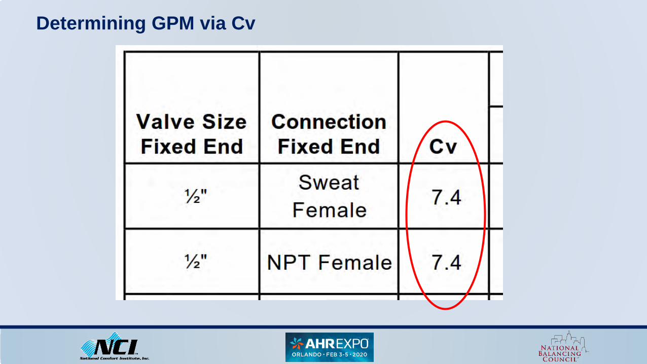
Determining GPM via Cv

ExampleUsing the following chart we can calculate the gpm through the 1/2” strainer and an actual ΔP of .5 psi.
GPM = Cv x √ΔP
GPM = Cv x √.5
GPM = Cv x .71
GPM = 7.4 x .71
GPM = 5.23 GPM

Auto Flow Valves
Contain a pressure regulating cartridge and a flow control insert that are factory preset.
No need to set the valves in the field.
For field commissioning, a pressure drop across the valve can be taken to verify it is within the required pressure differential (± 5%).
Below and above PSID control range, MOST autoflow valves work as fixed orifice type valves and allow flow to vary.

Auto Flow Valves

Auto Flow Valves DO NOT Function Correctly if…
They are not sized correctly
They are installed the wrong direction
If the pump is oversized or undersized
If they have the wrong cartridge installed

Griswold Auto Flow Valves
1. Connect meter kit to test plugs located on valve body.
2. Determine pressure differential (PSID or feet of head) across flow limiting cartridge by subtracting downstream pressure from upstream pressure.
3. Determine which PSID control range the valve is set for. Nine are available.
Upper Limit
Lower Limit
PSID
Flow (GPM)

Griswold Auto Flow Valves
4.If PSID reading falls within the valve’s pressure differential range, then it is limiting flow rate with ±5% accuracy. Minimum pressure differential required for flow limiting is provided in the table.
5.If actual PSID reading lies outside valve’s PSID operating range, calculate how much the flow rate has varied from specified rate using equations and table.
Upper Limit
Lower Limit
PSID
Flow (GPM)

Griswold Auto Flow Valves
Where:
Q = Flow rate through the valve (gpm)
Q0 = Specified (factory set) flow rate of valve (gpm)
C1 - = Flow coefficient (table)
ΔP = Pressure differential across the valve
Q = C1 Q0 x √ΔP

ExampleIf the pressure differential reading across your valve is 3, the valve is pre-set at 50 gpm for an operating control range of 4-57 PSID, what is the flow through the valve?

ExampleIf the pressure differential reading across your valve is 3, the valve is pre-set at 50 gpm for an operating control range of 4-57 PSID, what is the flow through the valve?
Q = C1 Q0 x √ΔP
Q = .41 x 50 x √3
Q = .41 x 50 x 1.73
Q = 35.5 GPM

If the differential pressure is below the minimum needed to activate the autoflow piston. It is fully extended and acts as a fixed orifice.
With a fixed orifice, a Cv rating can be used to determine flow. The Cv must be provided by the manufacturer.
Determining Autoflow GPM Using Cv

For example, with the FDI / IMI Autoflow Valves.A below range example with a Cv of .71 x design flow (2-32 range). Or a Cv of .45 times design flow for the 5-60 range. The ATC is controlling gpm in this zone.
Determining Autoflow GPM Using Cv

ExampleWhat would actual flow be on an FDI autoflow tagged for 2.5 gpm @ 2-32 psi if the actual reading was 1.25 psi?
GPM = Cv x √ΔP
GPM = .71 x √1.25
GPM = .71 x 1.12
GPM = .79

Determining Flow via BTU Calculations (Heat Transfer Method)
You can determine gpm by pressure drop, use ultra sonic meters or calculate Btus off of air flow and hydronic ΔT.
Btu calculation can help confirm flow, so can Btu calculations.
When test ports are not installed, or not accessible, it is perfectly fine to use an ultra sonic meter.
Note: in some situations where the use of an ultra sonic meter is impractical and/or impossible due to access, length of piping and transitions, etc., determining gpm via Btu calculations is an acceptable, although not ideal method.

Determining Flow via BTU Calculations (Heat Transfer Method)

Example
Step One: Calculate the coil heating capacity for VAV 7: BTUs = ΔT x CFM x 1.08
BTUs = (103.31 – 55.00) x 259 x 1.08
BTUs = 48.31 x 259 x 1.09
BTUs = 13, 513
Note that 13,513 (field calculation) - 13,570 (cut sheet value) = 57 Btus, or .006% variance. Very often the air side and hydronic side Btus will not line up exactly.

Example
Step Two: Calculate the gpm for VAV 7: GPM = BTUs ÷ (ΔT x 500)
GPM = 13,570 ÷ (34.33 x 500)GPM = 13,570 ÷ 17,165GPM = .79

This method can also be applied to chilled water hydronic systems, however total BTUs will need to be calculated by converting Wet Bulb air temperatures to Enthalpy. This can be done by using a Psychrometric Chart or an Enthalpy Chart, since Wet Bulb and Enthalpy Run parallel on the Psych Chart.
Determining Flow via BTU Calculations (Heat Transfer Method)


Ultrasonic Flow Meters
Recently, ultrasonic flow meters have come down considerably in cost. The improved technology is very handy to have. There are two types of ultrasonic meters:

Ultrasonic Flow Meters
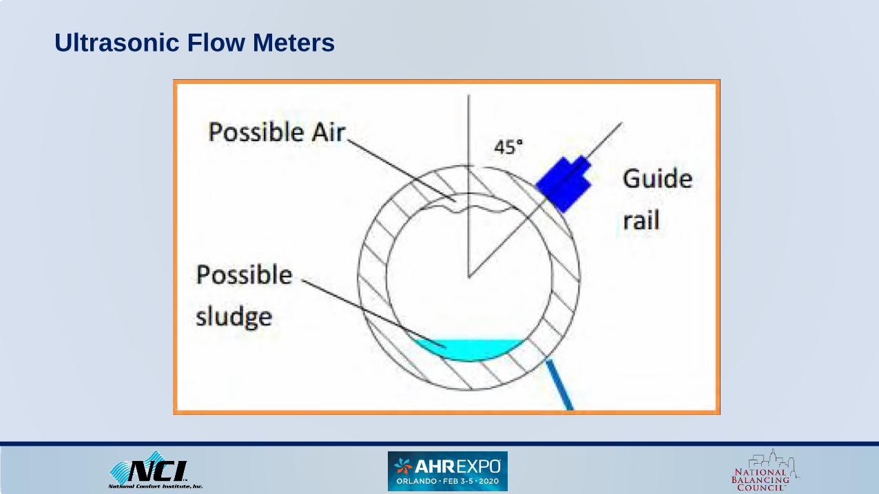
Ultrasonic Flow Meters

Ultrasonic Flow Meters

In-Line Flow Stations
Are often very accurate and reliable, but still can fall victim to human error and improper installation.
The TAB Professional should always confirm calibration of inline flow stations.

Conclusions
1. Setting the Pump using Pump Curves2. Triple-Duty Valves3. Coil Pressure Drop4. Circuit Setters5. Venturis6. Autoflow Valves7. Cv Rating8. Heat Transfer9. Ultrasonic Meters10. In-line Flow Stations

1. No method of reading flow is perfect or infallible.2. It is not possible to properly determine flow without the right instruments.3. It is not possible to properly determine flow without the correct manufacturer’s
data sheets.4. All readings should be checked against other readings in the system.5. All readings should make sense mathematically.
Conclusions

Reading Chiller / HX flow and comparing to Pump and Coil Flow
Setting Flow at Pump Using Manufacture’s
Pump Curve
Properly Reading all Flow Stations and comparing
to Pump Flow
Conclusions

TAB Professionals owe to the end user and our trade to use these instruments and methods in order to provide the most accurate system evaluations possible.
If these methods and instruments are being used and applied on a constant basis, they should be.
Ultimately, the TAB Professional must take multiple readings, with multiple instruments across a single system, and triangulate those readings, and compare them to known values in order to support their readings.
Conclusions

Questions?