Basic I/O Interface - fac.ksu.edu.sa · CEN433 -King Saud University 3 Mohammed Amer Arafah I/O...
35
1 Basic I/O Interface CEN433 King Saud University Dr. Mohammed Amer Arafah
Transcript of Basic I/O Interface - fac.ksu.edu.sa · CEN433 -King Saud University 3 Mohammed Amer Arafah I/O...

1
Basic I/O Interface
CEN433
King Saud University
Dr. Mohammed Amer Arafah
Mohammed Amer Arafah2CEN433 - King Saud University
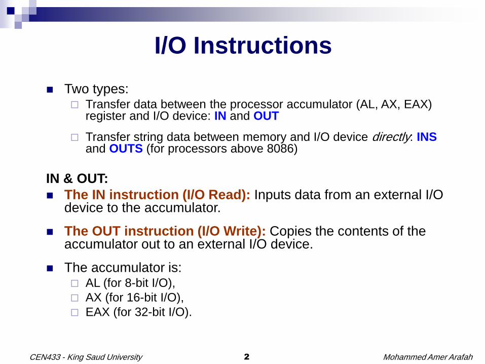
I/O Instructions
Two types: Transfer data between the processor accumulator (AL, AX, EAX)
register and I/O device: IN and OUT
Transfer string data between memory and I/O device directly: INSand OUTS (for processors above 8086)
IN & OUT:
The IN instruction (I/O Read): Inputs data from an external I/O device to the accumulator.
The OUT instruction (I/O Write): Copies the contents of the accumulator out to an external I/O device.
The accumulator is: AL (for 8-bit I/O),
AX (for 16-bit I/O),
EAX (for 32-bit I/O).

Mohammed Amer Arafah3CEN433 - King Saud University
I/O Addresses
As with memory, I/O devices have I/O addresses (addresses for the I/O port)
Up to 64K I/O bytes can be addressed
The 16-bit port address appears on address bus bits A15-A0 This allows I/O devices at addresses 0000H-FFFFH
Two ways to specify an I/O port address:
An 8-bit immediate (fixed) address. For example:IN AX, p8 ; Reads a word from port p8
0000H-00FFH (can only see the first 256 addresses)
A 16-bit address located in register DX. For example:OUT DX, AL ; Outputs the byte in AL to the port whose address is in DX
0000H-FFFFH (upto 64K addresses).
i.e. High port addresses are accessible only through DX addressing
FFFF
64K 8
0000
I/O Space
Mohammed Amer Arafah4CEN433 - King Saud University
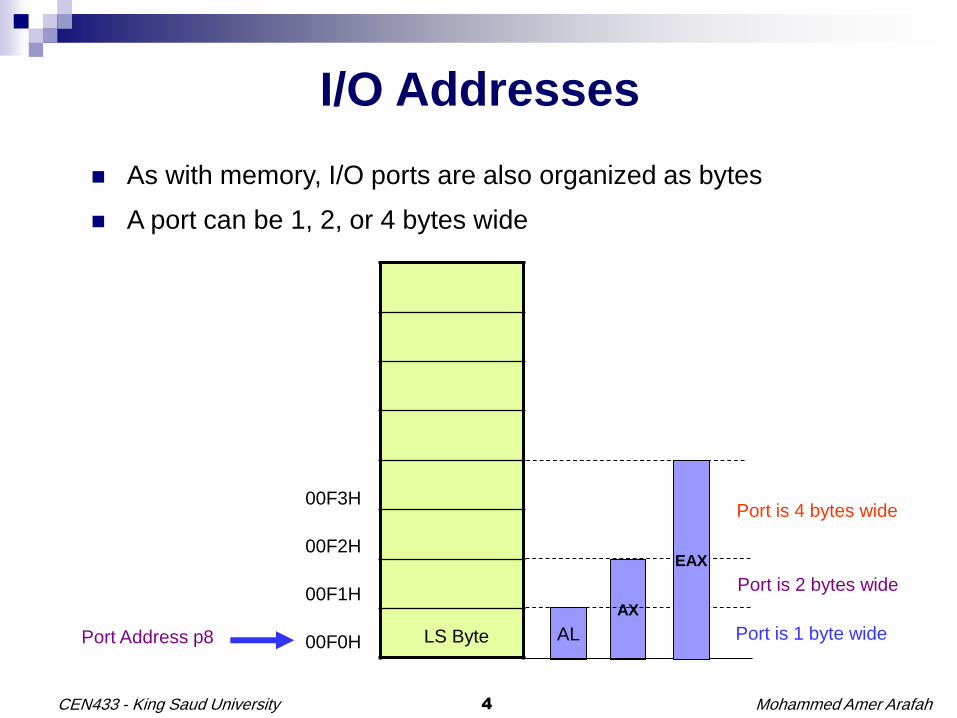
I/O Addresses
As with memory, I/O ports are also organized as bytes
A port can be 1, 2, or 4 bytes wide
00F3H
00F2H
00F1H
00F0H LS BytePort Address p8 AL
AX
Port is 1 byte wide
Port is 2 bytes wide
Port is 4 bytes wide
EAX
Mohammed Amer Arafah5CEN433 - King Saud University
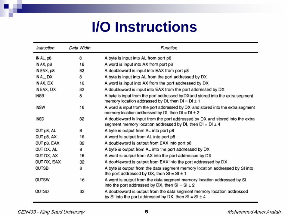
I/O Instructions

Mohammed Amer Arafah6CEN433 - King Saud University
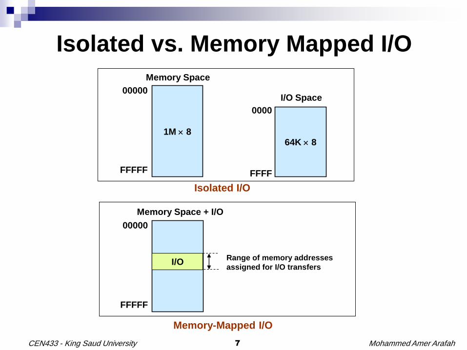
Isolated vs. Memory Mapped I/O
I/O can be either: Isolated, or
Memory mapped
Isolated I/O: uses the dedicated I/O instructions (IN, OUT and INS, OUTS) and has its own address space for I/O ports (0000H-FFFFH)- isolated from the memory address space
Memory mapped I/O: uses memory reference instructions , e.g. MOV, and a region of the memory address map. So address space is shared between memory and I/O (used by only one of them)
Both techniques can be used with Intel processors
But most Intel-based systems e.g. the PC, use isolated I/O
Some other processors do not have dedicated I/O instructions and therefore use only memory-mapped I/O addressing, e.g. the PowerPC microprocessor (Macintosh computers)
Mohammed Amer Arafah7CEN433 - King Saud University
Isolated vs. Memory Mapped I/O
1M 864K 8
Memory Space
I/O Space
0000
FFFF
00000
FFFFF
Isolated I/O
Memory Space + I/O
00000
FFFFF
Memory-Mapped I/O
I/ORange of memory addresses
assigned for I/O transfers
Mohammed Amer Arafah8CEN433 - King Saud University
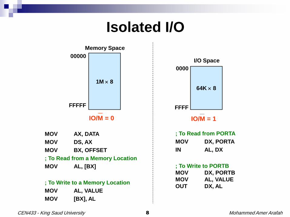
Isolated I/O
1M 864K 8
Memory Space
I/O Space
0000
FFFF
00000
FFFFF
IO/M = 0 IO/M = 1
MOV AX, DATA
MOV DS, AX
MOV BX, OFFSET
; To Read from a Memory Location
MOV AL, [BX]
; To Write to a Memory Location
MOV AL, VALUE
MOV [BX], AL
; To Read from PORTA
MOV DX, PORTA
IN AL, DX
; To Write to PORTB
MOV DX, PORTB
MOV AL, VALUE
OUT DX, AL
Mohammed Amer Arafah9CEN433 - King Saud University
The PC I/O space
The PC I/O space mainly exists at locations below I/O port 0400H
Main board devices appear at addresses 0000H through 00FFH
Modern components appear at I/O locations above 0400H
The slide on the next page shows many of the I/O devices
found in the personal computer
Mohammed Amer Arafah10CEN433 - King Saud University
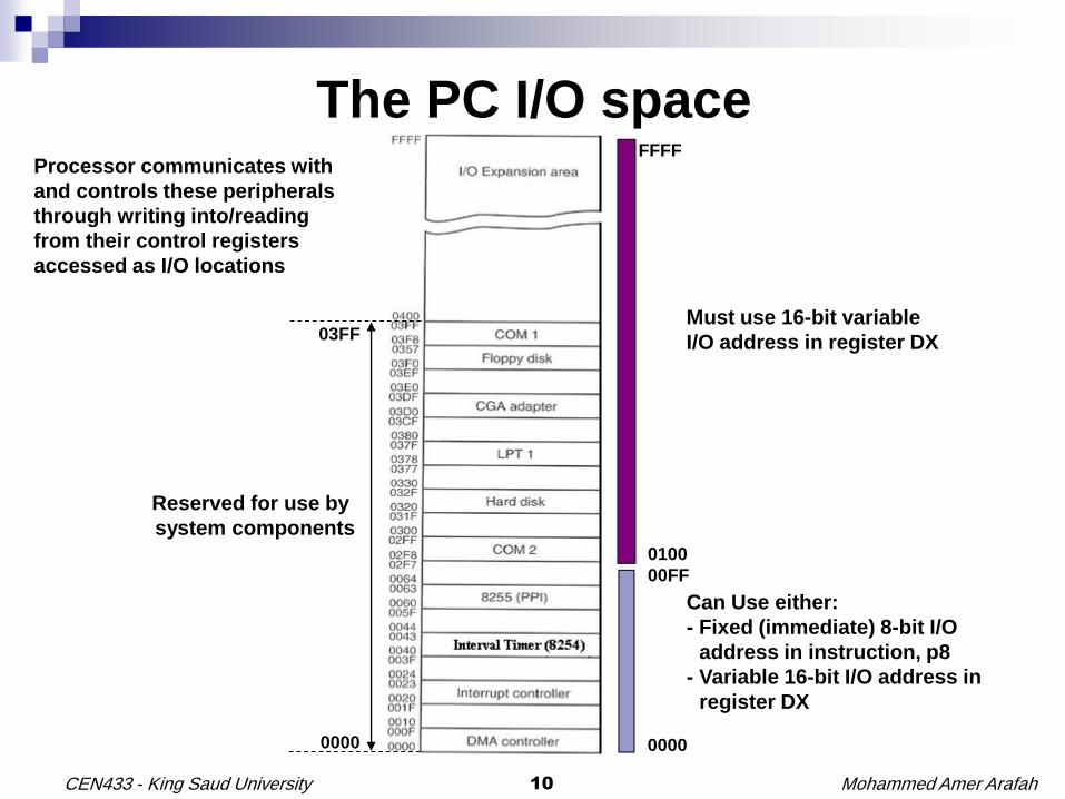
The PC I/O space
Reserved for use by
system components
Can Use either:
- Fixed (immediate) 8-bit I/O
address in instruction, p8
- Variable 16-bit I/O address in
register DX
0100
00FF
Processor communicates with
and controls these peripherals
through writing into/reading
from their control registers
accessed as I/O locations
0000
FFFF
Must use 16-bit variable
I/O address in register DX03FF
0000

Mohammed Amer Arafah11CEN433 - King Saud University
IN & OUT Instructions
; To write the data 00H into Output port 62H
MOV AL,00H
OUT 62H,AL
; or
MOV AL,00H
MOV DX,62H
OUT DX,AL
; To read a byte from Input port address 71H
IN AL,71H
; or
MOV DX,71H
IN AL,DX

Mohammed Amer Arafah12CEN433 - King Saud University
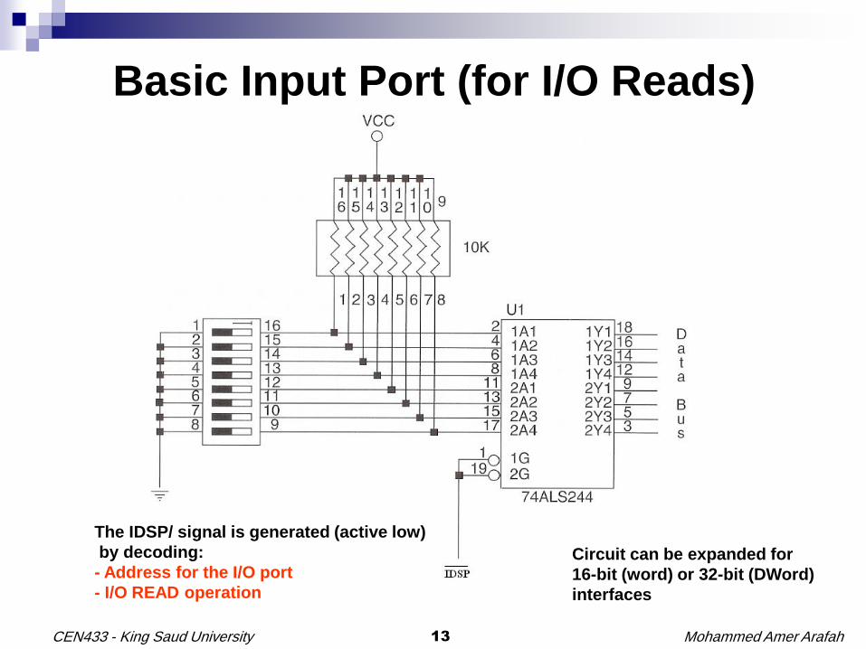
Basic Input Port (for I/O Reads)
The basic input port connects an external set of bits to the
microprocessor data bus whenever the microprocessor
executes the IN instruction with the I/O port address
External device puts data on the microprocessor data bus
Must include a 3-state (Tri-State) buffer to limit access to the processor data bus to the duration of executing the I/O instruction only
Mohammed Amer Arafah13CEN433 - King Saud University
Basic Input Port (for I/O Reads)
The IDSP/ signal is generated (active low)
by decoding:
- Address for the I/O port
- I/O READ operation
Circuit can be expanded for
16-bit (word) or 32-bit (DWord)
interfaces

Mohammed Amer Arafah14CEN433 - King Saud University
Basic Input Port (for I/O Reads)

Mohammed Amer Arafah15CEN433 - King Saud University
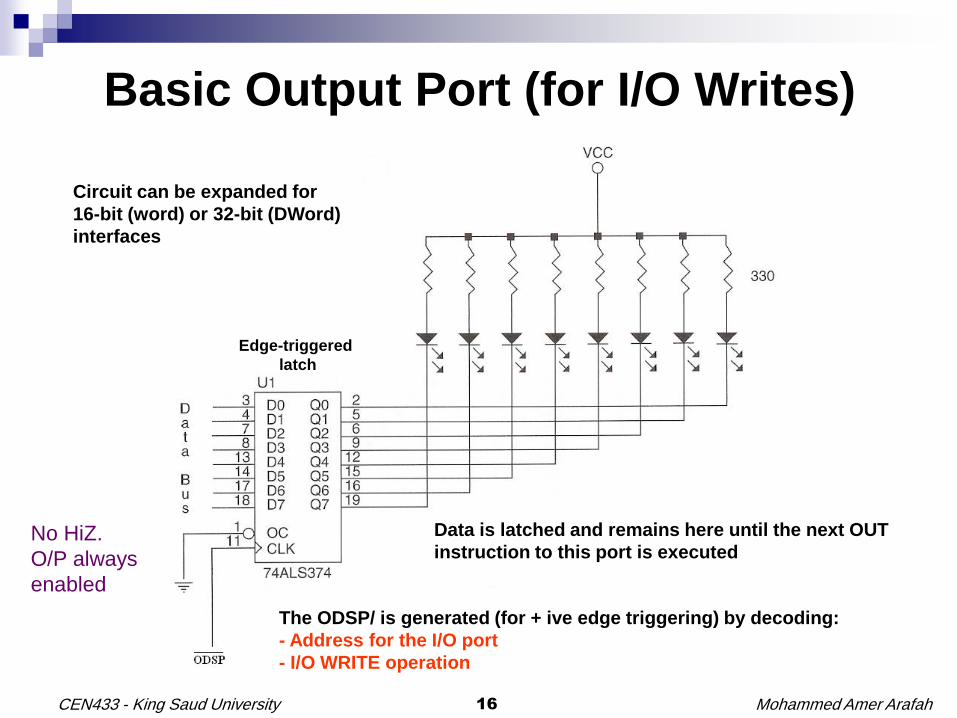
Basic Output Port (for I/O Writes)
The basic output port writes data from the microprocessor
data bus to an output port whenever the microprocessor
executes the OUT instruction with the I/O port address
Must latch the processor data put on the bus during the
I/O instruction to make it available indefinitely for the port
No need for 3-state (Tri-State) buffers as the data bus is
at the input side of the latch
Mohammed Amer Arafah16CEN433 - King Saud University
Basic Output Port (for I/O Writes)
Data is latched and remains here until the next OUT
instruction to this port is executed
Circuit can be expanded for
16-bit (word) or 32-bit (DWord)
interfaces
The ODSP/ is generated (for + ive edge triggering) by decoding:
- Address for the I/O port
- I/O WRITE operation
Edge-triggered
latch
No HiZ.
O/P always
enabled

Mohammed Amer Arafah17CEN433 - King Saud University
Basic Output Port (for I/O Writes)
Mohammed Amer Arafah18CEN433 - King Saud University
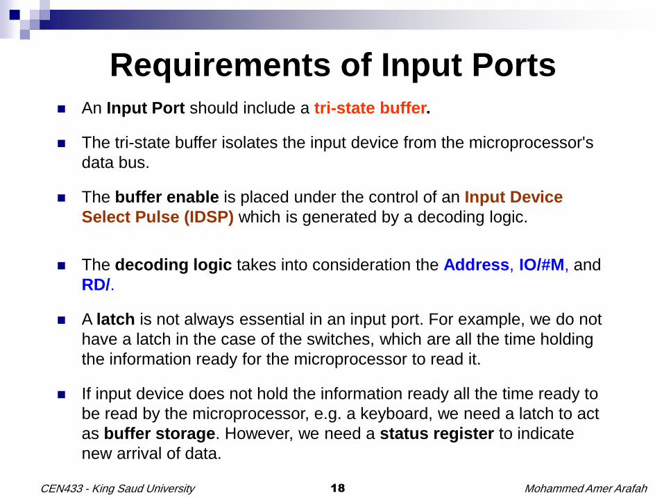
Requirements of Input Ports An Input Port should include a tri-state buffer.
The tri-state buffer isolates the input device from the microprocessor's
data bus.
The buffer enable is placed under the control of an Input Device
Select Pulse (IDSP) which is generated by a decoding logic.
The decoding logic takes into consideration the Address, IO/#M, and
RD/.
A latch is not always essential in an input port. For example, we do not
have a latch in the case of the switches, which are all the time holding
the information ready for the microprocessor to read it.
If input device does not hold the information ready all the time ready to
be read by the microprocessor, e.g. a keyboard, we need a latch to act
as buffer storage. However, we need a status register to indicate
new arrival of data.
Mohammed Amer Arafah19CEN433 - King Saud University
Requirements of Output Ports
An Output Port does not require a tri-state buffer because the
output port never tries to drive the microprocessor's data bus.
An Output Device Select Pulse (ODSP) is generated by a
decoding logic.
The decoding logic takes into consideration the Address,
IO/#M, and WR/.
A latch is essential in the case of output port.
Mohammed Amer Arafah20CEN433 - King Saud University
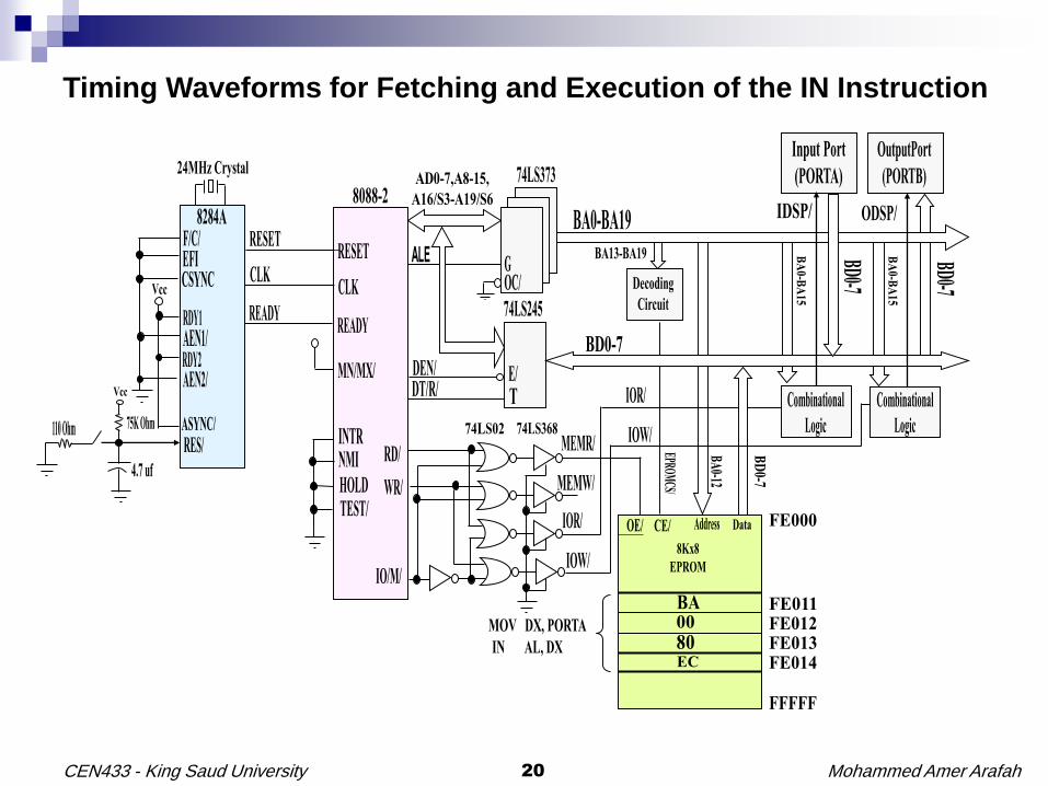
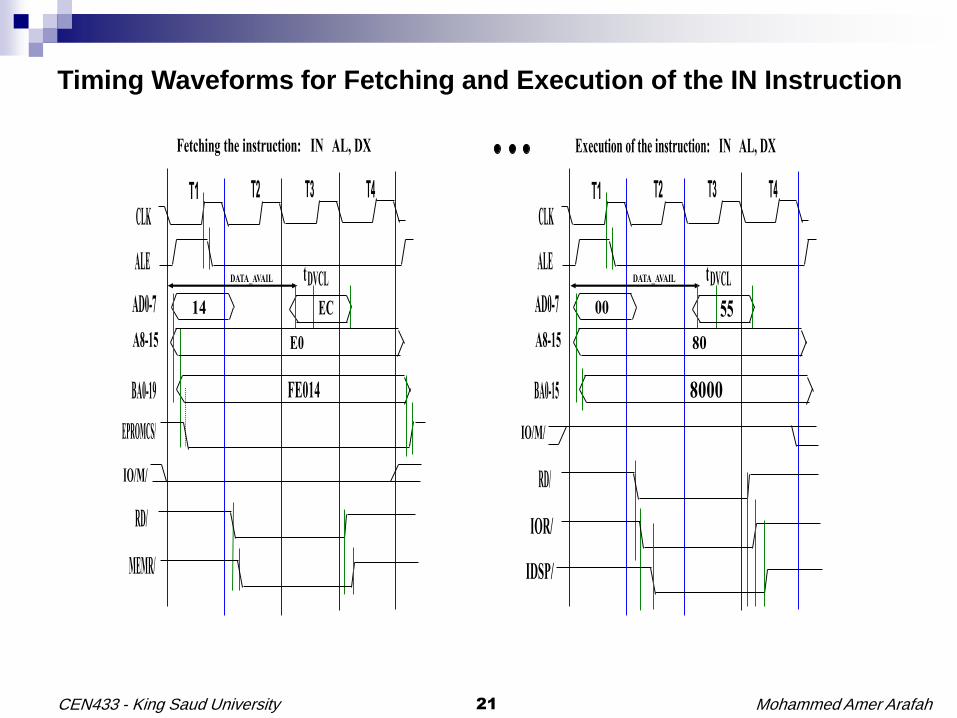
Timing Waveforms for Fetching and Execution of the IN Instruction
Mohammed Amer Arafah21CEN433 - King Saud University
Timing Waveforms for Fetching and Execution of the IN Instruction
Mohammed Amer Arafah22CEN433 - King Saud University
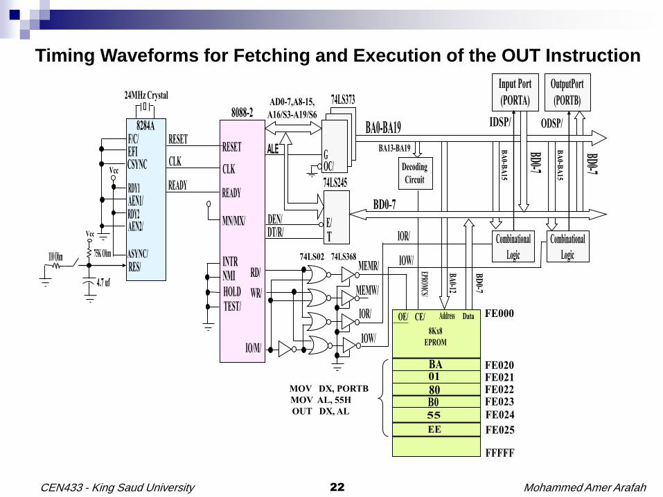
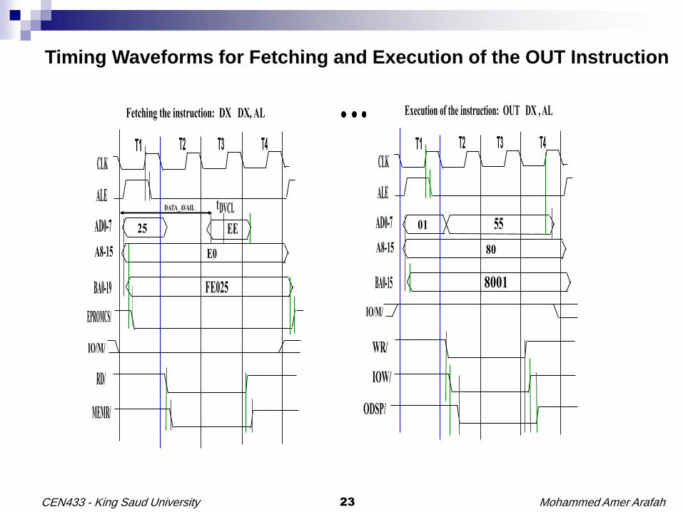
Timing Waveforms for Fetching and Execution of the OUT Instruction
Mohammed Amer Arafah23CEN433 - King Saud University
Timing Waveforms for Fetching and Execution of the OUT Instruction

Mohammed Amer Arafah24CEN433 - King Saud University
Optional Topic

Mohammed Amer Arafah25CEN433 - King Saud University
Conditional I/O
START: MOV DX, STATUS_PORT
AGAIN: IN AL, DX
TEST AL, 00000001B
JZ AGAIN
;
MOV DX, DATA_PORT
IN AL, DX
JMP START
Isolated I/O
START: MOV BX, STATUS_PORT
AGAIN: MOV AL, [BX]
TEST AL, 00000001B
JZ AGAIN
;
MOV BX, DATA_PORT
IN AL, [BX]
JMP START
Memory-Mapped I/O

Mohammed Amer Arafah26CEN433 - King Saud University
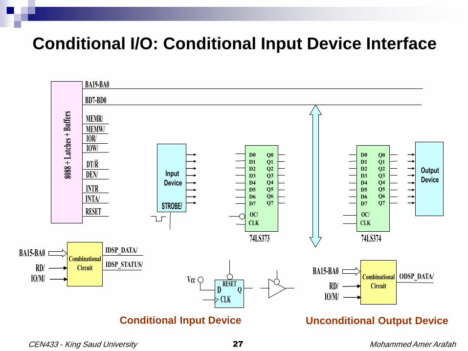
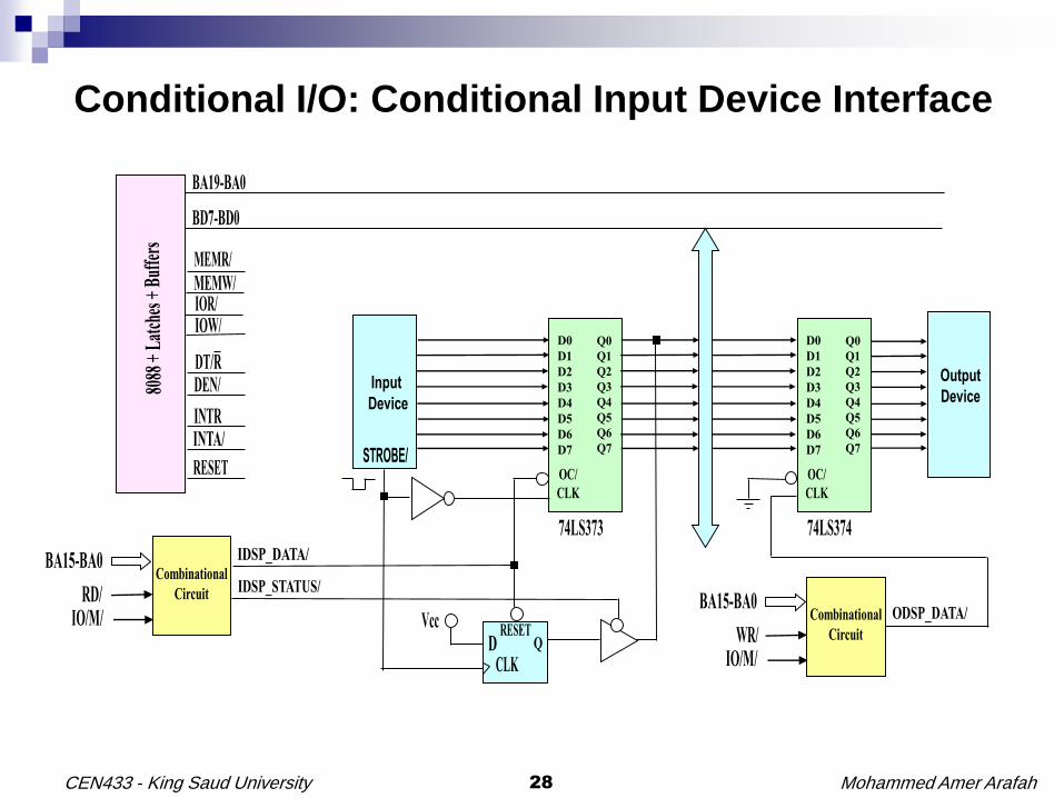
Conditional I/O: Conditional Input Device Interface
Mohammed Amer Arafah27CEN433 - King Saud University
Conditional I/O: Conditional Input Device Interface
Conditional Input Device Unconditional Output Device
Mohammed Amer Arafah28CEN433 - King Saud University
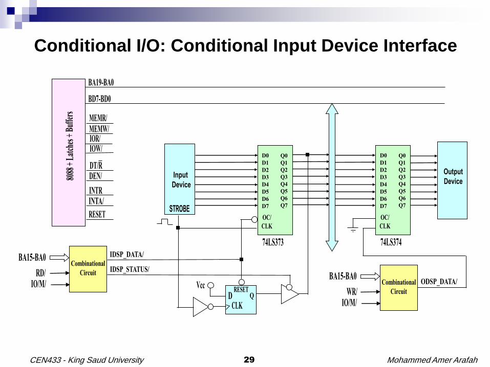
Conditional I/O: Conditional Input Device Interface
Mohammed Amer Arafah29CEN433 - King Saud University
Conditional I/O: Conditional Input Device Interface

Mohammed Amer Arafah30CEN433 - King Saud University
Conditional I/O: Conditional Input Device Interface
Mohammed Amer Arafah31CEN433 - King Saud University
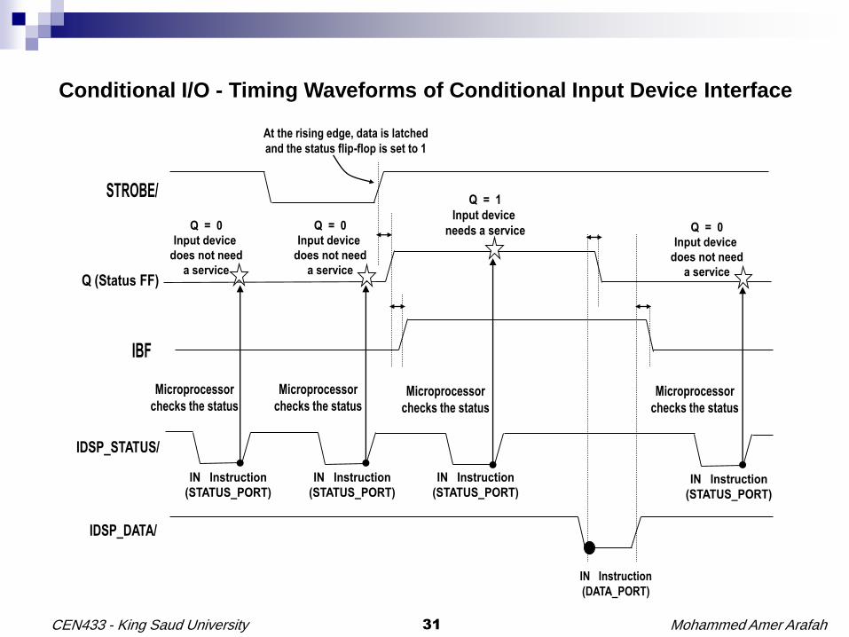
Conditional I/O - Timing Waveforms of Conditional Input Device Interface
Mohammed Amer Arafah32CEN433 - King Saud University
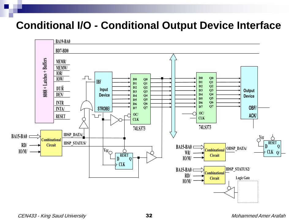
Conditional I/O - Conditional Output Device Interface

Mohammed Amer Arafah33CEN433 - King Saud University
Conditional I/O - Conditional Output Device Interface
Mohammed Amer Arafah34CEN433 - King Saud University
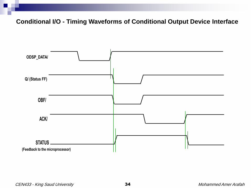
Conditional I/O - Timing Waveforms of Conditional Output Device Interface
Mohammed Amer Arafah35CEN433 - King Saud University
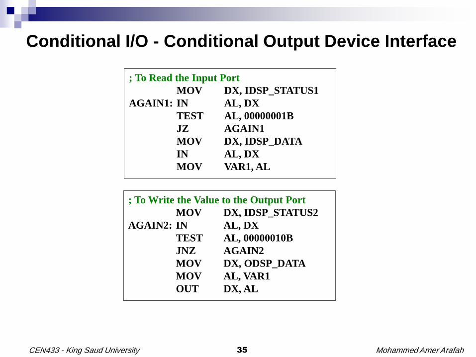
Conditional I/O - Conditional Output Device Interface
; To Read the Input Port
MOV DX, IDSP_STATUS1
AGAIN1: IN AL, DX
TEST AL, 00000001B
JZ AGAIN1
MOV DX, IDSP_DATA
IN AL, DX
MOV VAR1, AL
; To Write the Value to the Output Port
MOV DX, IDSP_STATUS2
AGAIN2: IN AL, DX
TEST AL, 00000010B
JNZ AGAIN2
MOV DX, ODSP_DATA
MOV AL, VAR1
OUT DX, AL