Basic-Hyd-Prop..doc
7
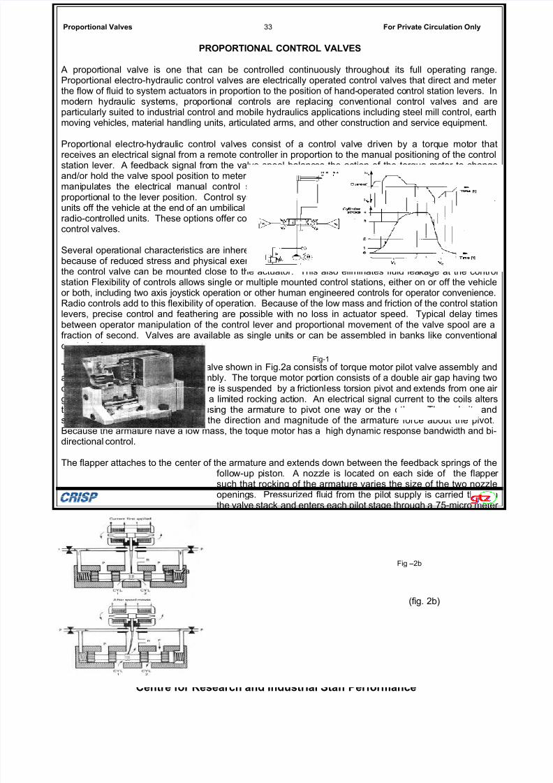
Proportional Valves 33 For Private Circulation Only PROPORTIONAL CONTROL VALVES A propor tional valve is one that can be controlled continuously throughou t its full operating range. Proportional electro-hydraulic control valves are electrically operated control valves that direct and meter the flow of fluid to system actuators in propor tion to the position of hand- operated co ntrol station levers. In mod ern hydr auli c syste ms, pro port iona l con trols are rep lacin g conv enti onal cont rol valv es and are particularly suited to industrial control and mobile hydraulics applications including steel mill control, earth moving vehicles, material handling units, articulated arms, and other construction and service equipment. Prop ortional electro-hydraulic contr ol valv es consist of a control valv e driv en by a torq ue mot or that receives an electrical signal from a remote controller in proportion to the manual positioning of the control station lever. A feedback signal fro m the valve spool balanc es the action of the torque mo tor to change and/or hold the valv e spool position to meter flow in propo rtion to the control lever posi tion. The opera tor mani pula tes the electrical manual cont rol station pro vidi ng the elec tric al sign al to the control valv e proportio nal to the lever position. Control systems can be mounted to control pan els, or held as portable units off the vehicle at the end of an umbilical control cable. They also can be completely portable by using radio-controlled units. These options offer convenie nce and flexibility not possible with stationary mounted control valves. Several oper ational character istics are inherent to such a system. Operator fatig ue is drastically lowered because of reduc ed stress and physical exertio n requireme nts. Hydraulic plumbi ng is simplified because the control valve can be moun ted close to the actuator. This also eliminates fluid lea kage at the control station Flexibility of controls allows single or multiple mounted control stations, either on or off the vehicle or both, including two axis joystick operation or other human engineered controls for operator convenience. Radio controls add to this flexibility of operatio n. Because of the low mass and friction of the control station levers, precise contr ol and feathering are p ossible with no loss in actuator speed. Typical delay times between operator manipulation of the control lever and proportional movement of the valve spool are a fraction of second. Valves are available as single uni ts or can be assembled in banks like conventiona l control valves. The proportional electro-hydraulic valve shown in Fig.2a consists of torque motor pilot valve assembly and a four-way power stage val ve assembly. The torque motor po rtion consists of a double air gap having two coils and two magnets. The armature is suspended by a frictionl ess torsion pivot and extends from one air gap to the oth er. It can move with a limited rocking acti on. An electrical sign al current to th e coils alters the per manent mag netic field causi ng the arma ture to piv ot one way or the othe r. The pol arit y and strength of the current determine the direction and magnitude of the armature force about the pivot. Because the armat ure have a low mass, the toque motor has a high dynamic resp onse bandwid th and bi- directional control. The flapper attaches to the center of the armature and extends down between the feedback spring s of the follo w-up p iston . A nozz le is loca ted on e ach sid e of the fla ppe r such that rocking of the armature varies the size of the two nozzle opening s. Pressurized flu id from the pilo t supply is carried thr ough the valve stack and enters each pilot stage through a 75-micro meter filter screen. The fluid the n passes thr ough two fixe d orifices, one upstream o f each nozzle . Discharge flu id from the no zzle passes out through a drilling in the power valve spool to a tank cavity in the power valv e body. The pressu res between e ach nozzle and fixed orifice are porte d to opposite ends of the spool centerli ne. The level of these pressures holds the follow-up piston in continuous contact with the end of the po wer valve spool . The differen tial between the pressures, as varied by the flapper motion between the nozzles, creates the driving force on the power valve spool and the follow-up piston. Essen tiall y, the double nozzle flap per valve is a hydr auli c resi stance brid ge circ uit with two par allel connecting flow paths. Figure 4 shows how t he bridge circuit works. Pressurized fluid pass es throug h both paths from a common supply port P s to a common return port P t -. Each flow path has an upstr eam orifice and a down stre am nozzle, w ith an outpu t port locate d between the orifice and the nozzl e. The flap per is loca ted equid istan t betw een the two nozz les. Flap per to nozzle spacin g determines the Centre for Research and Industrial Staff Performance Fig –2a Fig –2b Fig-1 (fig. 2b)
-
Upload
sourabh-khandelwal -
Category
Documents
-
view
218 -
download
0
Transcript of Basic-Hyd-Prop..doc
7/30/2019 Basic-Hyd-Prop..doc
http://slidepdf.com/reader/full/basic-hyd-propdoc 1/7
Proportional Valves 33 For Private Circulation Only
PROPORTIONAL CONTROL VALVES
A proportional valve is one that can be controlled continuously throughout its full operating range.Proportional electro-hydraulic control valves are electrically operated control valves that direct and meter the flow of fluid to system actuators in proportion to the position of hand-operated control station levers. Inmodern hydraulic systems, proportional controls are replacing conventional control valves and areparticularly suited to industrial control and mobile hydraulics applications including steel mill control, earthmoving vehicles, material handling units, articulated arms, and other construction and service equipment.
Proportional electro-hydraulic control valves consist of a control valve driven by a torque motor thatreceives an electrical signal from a remote controller in proportion to the manual positioning of the controlstation lever. A feedback signal from the valve spool balances the action of the torque motor to changeand/or hold the valve spool position to meter flow in proportion to the control lever position. The operator manipulates the electrical manual control station providing the electrical signal to the control valveproportional to the lever position. Control systems can be mounted to control panels, or held as portableunits off the vehicle at the end of an umbilical control cable. They also can be completely portable by usingradio-controlled units. These options offer convenience and flexibility not possible with stationary mountedcontrol valves.
Several operational characteristics are inherent to such a system. Operator fatigue is drastically loweredbecause of reduced stress and physical exertion requirements. Hydraulic plumbing is simplified because
the control valve can be mounted close to the actuator. This also eliminates fluid leakage at the controlstation Flexibility of controls allows single or multiple mounted control stations, either on or off the vehicleor both, including two axis joystick operation or other human engineered controls for operator convenience.Radio controls add to this flexibility of operation. Because of the low mass and friction of the control stationlevers, precise control and feathering are possible with no loss in actuator speed. Typical delay timesbetween operator manipulation of the control lever and proportional movement of the valve spool are afraction of second. Valves are available as single units or can be assembled in banks like conventionalcontrol valves.
The proportional electro-hydraulic valve shown in Fig.2a consists of torque motor pilot valve assembly anda four-way power stage valve assembly. The torque motor portion consists of a double air gap having twocoils and two magnets. The armature is suspended by a frictionless torsion pivot and extends from one air gap to the other. It can move with a limited rocking action. An electrical signal current to the coils alters
the permanent magnetic field causing the armature to pivot one way or the other. The polarity andstrength of the current determine the direction and magnitude of the armature force about the pivot.Because the armature have a low mass, the toque motor has a high dynamic response bandwidth and bi-directional control.
The flapper attaches to the center of the armature and extends down between the feedback springs of thefollow-up piston. A nozzle is located on each side of the flapper such that rocking of the armature varies the size of the two nozzleopenings. Pressurized fluid from the pilot supply is carried throughthe valve stack and enters each pilot stage through a 75-micro meter filter screen. The fluid then passes through two fixed orifices, oneupstream of each nozzle. Discharge fluid from the nozzle passesout through a drilling in the power valve spool to a tank cavity in the
power valve body. The pressures between each nozzle and fixedorifice are ported to opposite ends of the spool centerline. The levelof these pressures holds the follow-up piston in continuous contactwith the end of the power valve spool. The differential between thepressures, as varied by the flapper motion between the nozzles,
creates the driving force on the power valve spool and the follow-up piston.
Essentially, the double nozzle flapper valve is a hydraulic resistance bridge circuit with two parallelconnecting flow paths. Figure 4 shows how the bridge circuit works. Pressurized fluid passes throughboth paths from a common supply port Ps to a common return port Pt-. Each flow path has an upstream
orifice and a down stream nozzle, with an output port located between the orifice and the nozzle. Theflapper is located equidistant between the two nozzles. Flapper to nozzle spacing determines the
Centre for Research and Industrial Staff Performance
Fig –2aFig –2b
Fig-1
(fig. 2b)

7/30/2019 Basic-Hyd-Prop..doc
http://slidepdf.com/reader/full/basic-hyd-propdoc 2/7
Proportional Valves 34 For Private Circulation Only
resistance of the nozzle. Steady flow, called quiescent flow, which passes through the circuit, is a functionof the orifice and nozzle size. When the flapper is in the neutral position, the bridge circuit is balanced andthe pressures at the output ports C1 & C2 are equal. Slight movement of the flapper causes the nozzles to
change sizes. This is how the flapper imbalances the bridge circuit and causes a differential pressure andflow from the output ports that shift the hydraulic valve main spool or in the case of two stage valves, toshift the boost valve spool. Flapper displacements as low as 0.004 in. will create a differential pressuregreater than 80% of the supply pressure with maximum output flow rates of 50% of the quiescent flow rate.
While the double nozzle valve is found in most high performance proportional valves, sliding spool pilotstage valves are found in low to modest performance mobile and industrial applications (fig. 5) thehydraulic bridge circuit used is very similar except that quiescent flow is across two meter-in control edgesand two meter-out control edges of the sliding spool pilot valve. Flow from the meter-out control spooledges drain to a common return port. The output ports to the boost stage of the valve are between each of the meter-in and meter out edges of the control valve spool. In the neutral position, quiescent flowacross meter-in and meter-out edges of the spool balance the pressure between the boost ports. Whenan electrical signal is sent to the solenoid actuator, the spool is displaced, imbalancing the bridge circuit byopening one set of meter-in/meter-out control edges and closing the other meter-in edge. This produces apressure flow situation at one output port or the other to shift the main spool or boost stage of the controlvalve. Because of the design, shifting the sliding spool pilot stage requires relatively large spooldisplacements (up to ± 0.030 in.) and requires high actuating forces from the solenoid actuator (with adither signal to minimize friction and hysteresis effects). The control spool and solenoid mass also limit the
dynamic response bandwidth to modest values unless high force output solenoids are used, but thisrequires high electrical inputs which generate unwanted heat.
Centre for Research and Industrial Staff Performance
Fig-4

7/30/2019 Basic-Hyd-Prop..doc
http://slidepdf.com/reader/full/basic-hyd-propdoc 3/7
Proportional Valves 35 For Private Circulation Only
The flow capacity and flow control characteristics of proportional electrohydraulic valves are determined bythe power stage valve spool configuration and flow characteristics that are altered by flow metering slots.Spools may have a number of configurations. Tandem center spools are used with constant flow pumpsupplies (fixed displacement pumps) (Fig.6). These spools have a bypass from pressure to return whenthe spool is centered in order to unload the hydraulic supply. As the spool moves to either side of center,the bypass closes off and the pump pressure builds throughout the hydraulic system upstream of theactuator.
Spool configurations for proportional valves operating on constant pressure systems may have either openor closed control ports when the spool is in the center position. Remember that an open center spool hasboth control ports open to return when the spool is centered. The tandem center bypass, which allowsstacking and independent supply to other loads, also diverts the constant volume pump to tank when thevalve spool is in the center position. The pressure lands usually are overlapped so that 10% to 30% of spool travel is necessary to close the return and open the cylinder port to pressure. This spoolconfiguration always is used to operate a man lift, as the open center assures operation of load holdingvalves at the lift cylinders which are required by OSHA and ANSI. Closed center spools are used withconstant pressure supplies (variable displacement pumps) The control is quite accurate and linear, but therequirement of a variable displacement pump increases the cost of the system considerably.
An alternative to the constant pressure system (variable volume pump) is to use a load demand pressureregulator (pilot operated unloading valve) on a constant volume fixed displacement pump. The result isthat all valves will have the same supply pressure, and that the system pressure will change toaccommodate maximum load. Standby pressure is essentially the same as the losses in the tandem
center valve system (200-300 lbf/in.2), and pump pressure builds as the load requires. The advantage of
this system over conventional tandem center constant volume systems is that the performance of allcontrol valves is immediate and non interactive as with true constant pressure systems. In both cases,however, the value of the pressure is dependent upon the valve controlling the maximum load, and whentwo or more valves are opened simultaneously, the valve controlling the least load will received priorityflow. A fixed displacement pump circuit with a cylinder demand pump unloading valve is shown in fig.7Notice that the open center valves require load holding valves at the cylinder ports.
Centre for Research and Industrial Staff Performance
Fig 6&7
Fig – 5

7/30/2019 Basic-Hyd-Prop..doc
http://slidepdf.com/reader/full/basic-hyd-propdoc 4/7
Proportional Valves 36 For Private Circulation Only
Figure 8 illustrates several controllers that are used with proportional control valves. Single-lever controllers con be moved back and forth to control thedirection of one double-acting cylinder or the forwardand reverse rotation of a motor. The center position isusually detented and removes electrical power. Twoaxis single-lever controllers are used to direct twoactuators hooked to a single piece of equipment suchas a loader fork on slides that lift as well as slide from
side to side. The single lever is moved back and forthor from side to side. Each direction has its own detent, feel-centering spring, potentiometer, and on-off switch. Two units of this style can be mounted side by side to provide convenient two-hand four-axiscontrol. External mounting of the controller requires asealed weather tight unit with a shroud to prevent
accidentalswitching.Multiplecontrol lever controllerssuch as thatin Fig.8b give the operator control over 2 to 6 lever switcheswhich can drive a signal proportional valve or a hydrostatic
pump stroker. The center position is neutral, and a"deadman" switch is located on the side to energize thecontrol levers. Custom designed control stations such asthat shown in Fig.8c are available for special useapplications. And self-contained radio controllers provideup to six proportional and 16 on-off functions. Individuallogic codes prevent erroneous control from electricalinterference or from other radio controllers. The integralradio transmitter operates from rechargeable batteries.
Electro-hydraulic proportional control valves can be used to control hydrostatic transmissions by replacing
the usual manual control lever of the variable displacement pump with an electric controller driven by abattery powered potentiometer. The electrical remote control for the hydrostatic pump is provided by aproportional valve mechanism like that shown in fig.9. In this application the position of the pump strokingmechanism is proportional to the electrical input, so a lever and spring connect from the strokingmechanism to the torque motor. When an electrical signal is applied from the hand controller to the torquemotor coils, the armature rocks either clockwise or counterclockwise. This torque displaces the flapper between the two nozzles. The differential nozzle flow moves the spool to either the right or left. The spoolcontinues to move until the feedback torque applied to the flapper from the spool valve counteracts theelectromagnetic torque. At this point the armature and flapper are returned to center, the spool stops andremains displaced until the electrical input signal changes to a new level. Valve spool position isproportional to the electrical signal. The actual flow from the valve to the stroking mechanism of the pumpdepends on the load pressure, and the stroking mechanism will move until it reaches a displacementwhere the feedback spring just counteracts the electrical input torque. At this point the valve has moved
back near its centered position. The control loop in this instance is open by its very nature, and it can beclosed only by the actions of the operator who must compensate for changes in the speed of the enginethat drives the hydrostatic pump or changes in the load.One of the problems inherent to proportional control valves is that operator effort to shift the controller isnot proportional to the output of the hydraulic valve, This can cause the actuator to start too quickly or exert too much force when the load resistance is encountered. For example, quick-shifting of the valve onthe tram motors on a tracked vehicle or on a fork lift drive could spill the load and break the machine,particularly at start-up or if the machine were stalled. Here the result could be personal injury as well asequipment damage.
The output force and velocity can be regulated by installing pressure or flow control valves at the actuators, but these have adjustment
Centre for Research and Industrial Staff Performance
Fig 8
Fig—8b
Fig -9
Fig - 10
7/30/2019 Basic-Hyd-Prop..doc
http://slidepdf.com/reader/full/basic-hyd-propdoc 5/7
Proportional Valves 37 For Private Circulation Only
limitations and often consume power needlessly. A more recently developed solution incorporates aninexpensive electrical programmable velocity control in the valve itself. Figure 10 illustrates thecharacteristics of such a circuit as it would be applied to a hydraulic cylinder or motor. The upper half of the figure illustrates the input voltage from a variable controller that, in this case, is switched abruptlyforward(positive) and then reversed (negative). The lower half of the figure illustrates adjustable (ramped)outputs at ports A and B, which are programmed with respect to acceleration, velocity, and deceleration.No matter how fast the controller is shifted, the output of the actuator is programmed to ramp the start-upacceleration, maximum velocity, and stopping acceleration in both directions within the safe limits of the
machine and operating personnel.
SERVO VALVES
A servo valve produces a continuously controlled output as a function of an electrical input signal. It doesthis by incorporating a feedback loop that compares the velocity, position. or force of the output actuator with the command signal sent to the control valve, and then makes corrections at the output for differencesin the two. The most common type of servo valve is a four-way valve, but three-way and two way portingconfigurations are also common.
In a proportional electro-hydraulic valve like that shown in Fig. 9, the position of the swash plate strokingmechanism on the pump is controlled by the position of the hand-operated proportional controller. Thecontrol loop in this instance is open by its very nature because the operator must compensate for changes
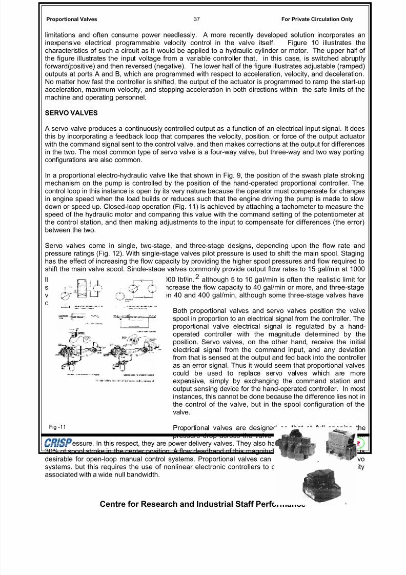
in engine speed when the load builds or reduces such that the engine driving the pump is made to slowdown or speed up. Closed-loop operation (Fig. 11) is achieved by attaching a tachometer to measure thespeed of the hydraulic motor and comparing this value with the command setting of the potentiometer atthe control station, and then making adjustments to the input to compensate for differences (the error)between the two.
Servo valves come in single, two-stage, and three-stage designs, depending upon the flow rate andpressure ratings (Fig. 12). With single-stage valves pilot pressure is used to shift the main spool. Staginghas the effect of increasing the flow capacity by providing the higher spool pressures and flow required toshift the main valve spool. Single-stage valves commonly provide output flow rates to 15 gal/min at 1000
lbf/in.2 drop and supply pressures to 5000 Ibf/in.2 although 5 to 10 gal/min is often the realistic limit for single-stage valves. Two-stage valves increase the flow capacity to 40 gal/min or more, and three-stagevalves are used with flow rates between 40 and 400 gal/min, although some three-stage valves have
capacities to 1000 gal/min.Both proportional valves and servo valves position the valvespool in proportion to an electrical signal from the controller. Theproportional valve electrical signal is regulated by a hand-operated controller with the magnitude determined by theposition. Servo valves, on the other hand, receive the initialelectrical signal from the command input, and any deviationfrom that is sensed at the output and fed back into the controller as an error signal. Thus it would seem that proportional valvescould be used to replace servo valves which are moreexpensive, simply by exchanging the command station andoutput sensing device for the hand-operated controller. In mostinstances, this cannot be done because the difference lies not in
the control of the valve, but in the spool configuration of thevalve.
Proportional valves are designed so that at full opening thepressure drop across the valve is only 5% to 10% of system
supply pressure. In this respect, they are power delivery valves. They also have a flow deadband of 20% to30% of spool stroke in the center position. A flow deadband of this magnitude creates a positive null that isdesirable for open-loop manual control systems. Proportional valves can be used in closed-loop servosystems. but this requires the use of nonlinear electronic controllers to compensate for the instabilityassociated with a wide null bandwidth.
Centre for Research and Industrial Staff Performance
Fig -11
7/30/2019 Basic-Hyd-Prop..doc
http://slidepdf.com/reader/full/basic-hyd-propdoc 6/7
Proportional Valves 38 For Private Circulation Only
Servo valves, on the other hand, are precision metering valves. Pressure drop across these valves at fullspool opening is commonly 33% of input pressure. This is done to ensure precision flow meteringcharacteristics, and because there is very little spool overlap, the flow headband is negligible. It must beremembered, however, that the amount of power transmitted through the valve is limited to 67% of theinput power.
Servo valves are used to control the velocity, position, force, and acceleration-deceleration rate of theactuator. Most servo valves control the flow rate to the actuator and are called flow control servo valves.
Servo valves that control and differentiate pressure to the load are called pressure control servo valves.Both functions can bc incorporated in one servo valve with the primary function being flow rate output(velocity control), with load pressure controlled as a function of the load resistance to motion. When flowand pressure are controlled in one servo valve, the valve provides a load flow rate as a function of the loadresistance to motion.
Which function the valve serves is determined by how the output is sensed, the configuration of the valve,and how the controller receives the feedback as a combinederror signal. Thus far we have discussed how a tachometer sensing the output speed of a hydraulic motor can be used tostroke the hydraulic pump. This is a flow control device. Here itwas not important what caused the speed to change at theoutput of the hydrostatic transmission output. It could have been
caused by a change in the output load, for example, as thevehicle traveled up or down a grade, or by a change in load onother parts of the system to cause the drive speed to the pumpto change. Either one would affect the speed of the output and if the command signal from the controller specified a certainspeed, then the feedback from the tachometer signal wouldcause an error signal to be sent to the controller.
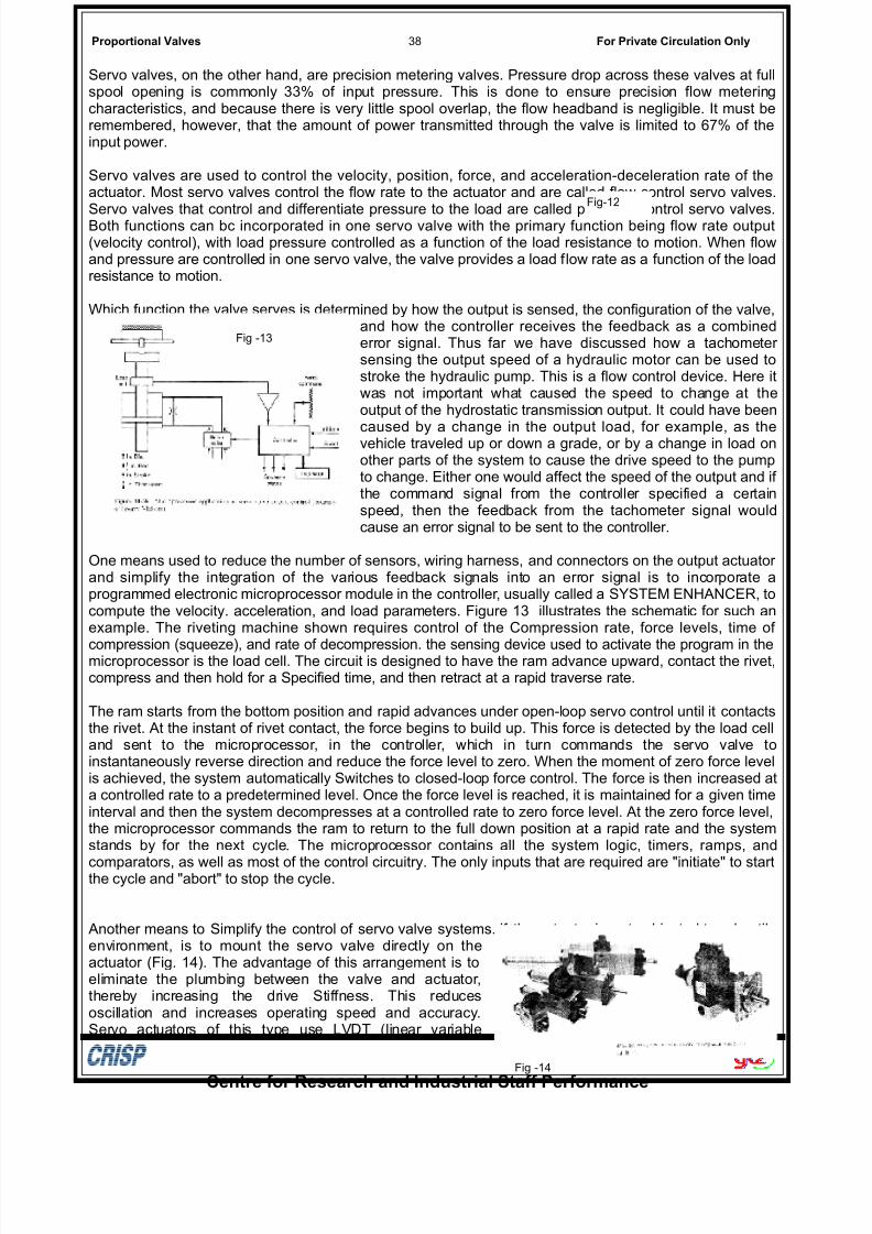
One means used to reduce the number of sensors, wiring harness, and connectors on the output actuator and simplify the integration of the various feedback signals into an error signal is to incorporate aprogrammed electronic microprocessor module in the controller, usually called a SYSTEM ENHANCER, tocompute the velocity. acceleration, and load parameters. Figure 13 illustrates the schematic for such anexample. The riveting machine shown requires control of the Compression rate, force levels, time of
compression (squeeze), and rate of decompression. the sensing device used to activate the program in themicroprocessor is the load cell. The circuit is designed to have the ram advance upward, contact the rivet,compress and then hold for a Specified time, and then retract at a rapid traverse rate.
The ram starts from the bottom position and rapid advances under open-loop servo control until it contactsthe rivet. At the instant of rivet contact, the force begins to build up. This force is detected by the load celland sent to the microprocessor, in the controller, which in turn commands the servo valve toinstantaneously reverse direction and reduce the force level to zero. When the moment of zero force levelis achieved, the system automatically Switches to closed-loop force control. The force is then increased ata controlled rate to a predetermined level. Once the force level is reached, it is maintained for a given timeinterval and then the system decompresses at a controlled rate to zero force level. At the zero force level,the microprocessor commands the ram to return to the full down position at a rapid rate and the systemstands by for the next cycle. The microprocessor contains all the system logic, timers, ramps, and
comparators, as well as most of the control circuitry. The only inputs that are required are "initiate" to startthe cycle and "abort" to stop the cycle.
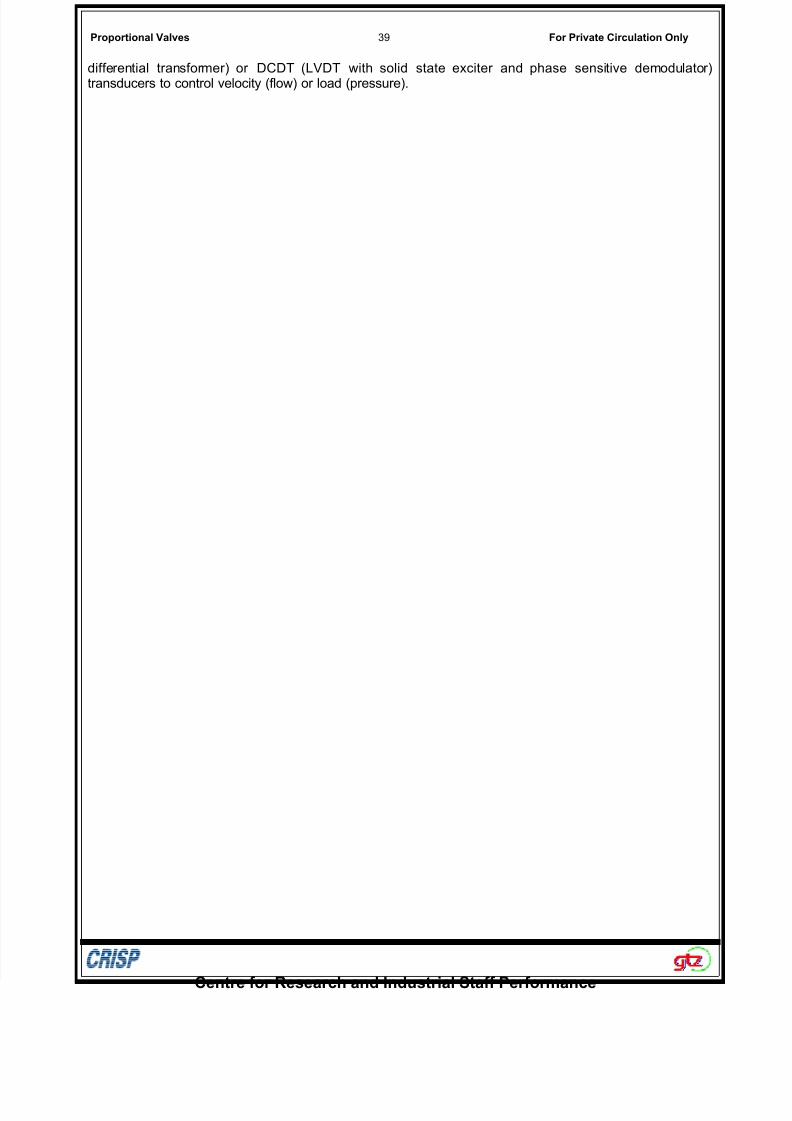
Another means to Simplify the control of servo valve systems. if the actuator is not subjected to a hostileenvironment, is to mount the servo valve directly on theactuator (Fig. 14). The advantage of this arrangement is toeliminate the plumbing between the valve and actuator,thereby increasing the drive Stiffness. This reducesoscillation and increases operating speed and accuracy.Servo actuators of this type use LVDT (linear variable
Centre for Research and Industrial Staff Performance
Fig-12
Fig -13
Fig -14
7/30/2019 Basic-Hyd-Prop..doc
http://slidepdf.com/reader/full/basic-hyd-propdoc 7/7
Proportional Valves 39 For Private Circulation Only
differential transformer) or DCDT (LVDT with solid state exciter and phase sensitive demodulator)transducers to control velocity (flow) or load (pressure).
Centre for Research and Industrial Staff Performance